EP2710340B1 - Camera arrangement for a vehicle and method for calibrating a camera and for operating a camera arrangement - Google Patents
Camera arrangement for a vehicle and method for calibrating a camera and for operating a camera arrangement Download PDFInfo
- Publication number
- EP2710340B1 EP2710340B1 EP11719817.6A EP11719817A EP2710340B1 EP 2710340 B1 EP2710340 B1 EP 2710340B1 EP 11719817 A EP11719817 A EP 11719817A EP 2710340 B1 EP2710340 B1 EP 2710340B1
- Authority
- EP
- European Patent Office
- Prior art keywords
- camera
- brightness
- value
- photometer
- values
- Prior art date
- Legal status (The legal status is an assumption and is not a legal conclusion. Google has not performed a legal analysis and makes no representation as to the accuracy of the status listed.)
- Not-in-force
Links
Images


Classifications
-
- G—PHYSICS
- G03—PHOTOGRAPHY; CINEMATOGRAPHY; ANALOGOUS TECHNIQUES USING WAVES OTHER THAN OPTICAL WAVES; ELECTROGRAPHY; HOLOGRAPHY
- G03B—APPARATUS OR ARRANGEMENTS FOR TAKING PHOTOGRAPHS OR FOR PROJECTING OR VIEWING THEM; APPARATUS OR ARRANGEMENTS EMPLOYING ANALOGOUS TECHNIQUES USING WAVES OTHER THAN OPTICAL WAVES; ACCESSORIES THEREFOR
- G03B7/00—Control of exposure by setting shutters, diaphragms or filters, separately or conjointly
- G03B7/08—Control effected solely on the basis of the response, to the intensity of the light received by the camera, of a built-in light-sensitive device
-
- H—ELECTRICITY
- H04—ELECTRIC COMMUNICATION TECHNIQUE
- H04N—PICTORIAL COMMUNICATION, e.g. TELEVISION
- H04N23/00—Cameras or camera modules comprising electronic image sensors; Control thereof
- H04N23/70—Circuitry for compensating brightness variation in the scene
- H04N23/71—Circuitry for evaluating the brightness variation
-
- G—PHYSICS
- G01—MEASURING; TESTING
- G01J—MEASUREMENT OF INTENSITY, VELOCITY, SPECTRAL CONTENT, POLARISATION, PHASE OR PULSE CHARACTERISTICS OF INFRARED, VISIBLE OR ULTRAVIOLET LIGHT; COLORIMETRY; RADIATION PYROMETRY
- G01J1/00—Photometry, e.g. photographic exposure meter
- G01J1/42—Photometry, e.g. photographic exposure meter using electric radiation detectors
- G01J1/4204—Photometry, e.g. photographic exposure meter using electric radiation detectors with determination of ambient light
-
- G—PHYSICS
- G03—PHOTOGRAPHY; CINEMATOGRAPHY; ANALOGOUS TECHNIQUES USING WAVES OTHER THAN OPTICAL WAVES; ELECTROGRAPHY; HOLOGRAPHY
- G03B—APPARATUS OR ARRANGEMENTS FOR TAKING PHOTOGRAPHS OR FOR PROJECTING OR VIEWING THEM; APPARATUS OR ARRANGEMENTS EMPLOYING ANALOGOUS TECHNIQUES USING WAVES OTHER THAN OPTICAL WAVES; ACCESSORIES THEREFOR
- G03B17/00—Details of cameras or camera bodies; Accessories therefor
- G03B17/18—Signals indicating condition of a camera member or suitability of light
-
- G—PHYSICS
- G03—PHOTOGRAPHY; CINEMATOGRAPHY; ANALOGOUS TECHNIQUES USING WAVES OTHER THAN OPTICAL WAVES; ELECTROGRAPHY; HOLOGRAPHY
- G03B—APPARATUS OR ARRANGEMENTS FOR TAKING PHOTOGRAPHS OR FOR PROJECTING OR VIEWING THEM; APPARATUS OR ARRANGEMENTS EMPLOYING ANALOGOUS TECHNIQUES USING WAVES OTHER THAN OPTICAL WAVES; ACCESSORIES THEREFOR
- G03B43/00—Testing correct operation of photographic apparatus or parts thereof
-
- B—PERFORMING OPERATIONS; TRANSPORTING
- B60—VEHICLES IN GENERAL
- B60R—VEHICLES, VEHICLE FITTINGS, OR VEHICLE PARTS, NOT OTHERWISE PROVIDED FOR
- B60R2300/00—Details of viewing arrangements using cameras and displays, specially adapted for use in a vehicle
- B60R2300/40—Details of viewing arrangements using cameras and displays, specially adapted for use in a vehicle characterised by the details of the power supply or the coupling to vehicle components
- B60R2300/402—Image calibration
-
- H—ELECTRICITY
- H04—ELECTRIC COMMUNICATION TECHNIQUE
- H04N—PICTORIAL COMMUNICATION, e.g. TELEVISION
- H04N17/00—Diagnosis, testing or measuring for television systems or their details
- H04N17/002—Diagnosis, testing or measuring for television systems or their details for television cameras
Definitions
- the invention relates to a camera arrangement for a vehicle, comprising a camera.
- the camera arrangement By means of the camera arrangement the brightness of the surroundings of the camera can be determined.
- the invention relates to a method for calibrating a camera for a vehicle and to a method for operating a camera arrangement.
- Document FR 2 783 613 A1 discloses a camera with four photometers for determining the brightness of an object which is captured by the camera when taking a picture of the object.
- the photometers comprise filters which ensure that the photometers record wavelengths of the radiation which are perceivable by the human eye.
- EP 1 790 541 A2 a system and method for detecting obstructions in a camera field of view is disclosed.
- a camera with a picture sensor and with a photometer in a camera arrangement for a vehicle.
- the photometer records the brightness of the surroundings of the camera with brightness being the visual perception in which a source appears to be radiating or reflecting light.
- it can, for example, be determined, if an area in front of the vehicle, the brightness of which is determined by the photometer, is a tunnel or not. If a tunnel is determined that way, corresponding functional units of the vehicle are activated. For instance the headlights may be switched on upon a tunnel coming within the capture range of the photometer.
- Such a photometer used in a camera arrangement for a vehicle usually also comprises a wavelength filter which lets through only the wavelengths perceivable by the human eye.
- the photometric quantity which is measured by the photometer is normally given in Energy per square centimeter.
- the photometer is also used to detect rain so that windscreen wipers of the vehicle can be activated accordingly. Also the headlights can be activated when darkness comes up, that is in dependence on the brightness determined by the photometer.
- a camera known from the state of the art, which comprises a photometer is relatively complex.
- a brightness value determined by the camera is compared to the brightness reference value to which the corresponding value is assigned, while the corresponding value is indicative of the photometric quantity.
- the camera arrangement operates without a photometer.
- Brightness values determined by the camera can be directly used to indicate the brightness of the surroundings of the camera, which is usually determined by a photometer.
- the photometer While the photometer, known from the state of the art, captures the wavelengths perceivable by the human eye, the camera captures a luminous flux the spectrum of wavelengths of which exceeds the spectrum which can be perceived by the human eye. This is because camera usually do not comprise a wavelength filter like the photometer. Thus, without prior calibration with the photometer the total luminous flux determined by the camera cannot directly be used for indicating the brightness that can be perceived by the human eye.
- the brightness value determined by the camera is compared to the reference value, to which the corresponding value measured by the photometer at the same brightness is assigned.
- the camera is calibrated with the photometer beforehand. This calibration makes it possible to establish a correlation between the illuminance which the photometer indicates at a given the brightness and the value of brightness determined by the camera at the same brightness. Consequently there are values stored in the storage device, which correlate brightness values determined by the camera exposed to a certain luminous flux to values indicating the luminous flux as determined by a photometer.
- the storage device can be integrated into the camera.
- the storage device can be integrated into a control device which can be coupled with the camera, and which is a separate component in the vehicle.
- the evaluation unit can be integrated into the camera as well, or else provided outside of the camera, particularly in the control device.
- the brightness which is determined by the camera arrangement takes into account brightness values determined per pixel in a picture captured by the camera.
- the brightness values determined per pixel are assigned to the values indicating the corresponding photometric quantity through comparison with the brightness reference values stored in the storage device.
- the values indicating the photometric quantity can be summed up in order to obtain the luminous flux captured by all pixels of the camera. Since the size of a pixel is known as well as the number of pixels of the camera, the luminous flux per surface unit can be indicated in lux, as it is usually done by a photometer.
- the brightness value determined per pixel can be correlated very fast and easily with the value indicative of the photometric quantity.
- At least two brightness reference values are stored in the storage device, wherein the reference values correspond to different gamma values of the camera.
- Certain cameras used in vehicle applications allow the so called gamma correction to be varied by pre-setting a gamma value within a range of gamma values.
- the gamma correction transforms an input quantity into an output quantity according to a certain rule, in order to convert a physically proportionally growing quantity to a quantity which the human sense does not perceive as growing linearly.
- a low preset gamma value of the camera leads to a relatively fast saturation of the pixels of the camera when brightness increases.
- the gamma value thus also reflects the response dynamics of the camera. Therefore with different gamma values and corresponding reference values stored in the storage device, a particularly precise detection of the brightness can be carried out.
- At least two brightness reference values are stored in the storage device, which correspond to different integration times of the camera.
- the integration time is the period of time during which a picture sensor of the camera accumulates charge carriers as the camera captures a picture. Storing different brightness reference values for different integration times is based on the finding that the luminous flux captured by the camera depends on the preset integration time. If the camera can be adjusted to different integration times, the consideration of the respective integration times allows for the determination of the brightness by utilization of the camera such as a photometer would do.
- An particularly fast and easy assignment of brightness reference values capturable by the camera to the corresponding values indicating the photometric quantity can be achieved, if, according to another advantageous embodiment of the invention, a plurality of such reference values are stored in a lookup-table provided in the storage device.
- the photometric quantity is indicative of a brightness which can be perceived by the human eye.
- the brightness determined by the camera can be used to activate functional units of the vehicle, which are to be activated in case of decreased brightness as sensed by humans. It is thereby possible to activate the headlights of the vehicle, either on entering a tunnel with the vehicle or when dawn is approaching or under particularly dark skies.
- the at least one brightness reference value can be stored as a greyscale value.
- a greyscale value is readily available when a black and white camera is used.
- CMOS or CCD complementary metal-oxide-semiconductor
- some conversion must be performed to determine greyscale values from the colour values. Different well known conversions exist and depend possibly on the image sensor used and/or the chosen weighting of the color channels.
- an angle of view capturable by an objective of the camera is preferably chosen around 40° as of classical camera. But wider angle of view could be conceivable like wider than 90°.
- the calibration process for calibrating a camera for a vehicle according to the invention is defined in independent Claim 1. It is thereby possible to refrain from providing a photometer in a vehicle, when using the camera arrangement comprising the camera and the storage device in order to determine the brightness of the camera's surroundings.
- the method for determining the brightness in a camera surrounding comprising a camera for a vehicle according to the invention is defined in independent Claim 2. Thus, it is possible to refrain from using a photometer when determining the brightness by means of the camera arrangement.
- the camera for carrying the process of claim 1 or the method of claim 2 is defined in independent claim 3.
- Fig. 1 shows a calibration device 10 for calibrating a camera 12 for a vehicle.
- the camera 12 and a photometer 14 which is arranged next to the camera 12 are arranged in a chamber 16.
- a diffusion filter 20 is arranged between a light source 18, the camera 12 and the photometer 14 which is located at the same distance from the diffusion filter 20 as the camera 12.
- the whole backside of the diffusion filter 20 is evenly exposed to the light source 18.
- the luminous flux 22 emitting from the diffusion filter 20 is homogeneous on the entire surface of the diffusion filter 20, which faces towards the camera 12 and the photometer 14.
- the camera 12 can be a black and white camera and in particular comprise a CMOS sensor as picture sensor.
- An objective lens of the camera 12 provides for an angle of view of 40°.
- On the photometer 14 a diaphragm 24 provides for an angle of view of 40° as well.
- the camera 12 can comprise a filter, which lets wavelengths up to 650 nm pass.
- a bit-depth of the camera 12 may be 12 bit.
- Other configurations for the camera 12 and the photometer 14 can be arranged for, provided that their parameters, for instance the number and the size of pixels of the camera 12 as well as of the active surface of the photometer 14 are known.
- the photometer 14 comprises a spectral filter so that the light sensitive elements of the photometer 14 only detect those wavelengths which can be perceived by the human eye.
- the camera 12 which is intended to be used in vehicles, comprises no such spectral filter, so that it can meet other tasks in a better way, for instance detecting road markings, rain or tunnels. Furthermore, the camera 12 can be designed for use at night or when the light conditions are poor.
- the photometer 14 When the camera 12 and the photometer 14 are exposed to the luminous flux 22 of the light source 18, the photometer 14 indicates the brightness in lux, that is lumen per square meter.
- the camera 12 captures a luminous flux 22 with a broader spectrum of wavelengths than the light perceivable by the human eye. Therefore from the luminous flux 22 captured by the camera 12 it cannot directly be inferred to the brightness perceivable by the human eye. However, it depends on this brightness, if the camera 12 is to be used to determine whether the vehicle comprising the camera 12 enters a tunnel or if the headlights of the vehicle shall be automatically activated in other circumstances with decreasing brightness.
- the photometer 14 comprises optical and numerical correction devices to allow for consideration of the laws of photometry. For instance the spectral filter is provided, and the cosine emission law is taken into consideration when analyzing the signals provided by the photometer 14. Through calibrating the camera 12 with the photometer 14 it is possible to refrain from providing such optical or numerical correction devices. The calibration also allows to ignore certain characteristics of the camera 12, for instance the recording noise, the transmission and the wavelength spectrum which passes through the optical units of the camera 12.
- the camera 12 can be parameterized, wherein the integration time as well as the gamma value can be adjusted.
- the integration time indicates during which time interval the photosensitive cells of the picture sensor of the camera 12 are exposed to the luminous flux 22 in order to generate a certain electrical signal.
- the dynamic of the cameras' response can be adjusted by setting the gamma value. For instance, a low gamma value results in a quick saturation of the pixels of the camera 12 when the brightness increases.
- an exemplary calculation is used to illustrate how the calibration of the camera 12 with the photometer 14 is carried out.
- the camera 12 is adjusted to a gamma value of 3 and an integration time of 243 lines.
- the integration time can be indicated in lines, provided the camera 12 is a line camera, which means that the picture sensor only comprises one light sensitive line.
- Such a line camera provides, given a predetermined angle of view, a particularly good spatial resolution.
- a line can be read by far more rapidly than an area.
- the camera 12 requires a predetermined time for scanning a line, it is possible to use the integration time expressed in lines to indicate how many times the same line is scanned during capture of a picture. Multiple scanning of the same line is particularly expedient when there are strong differences in brightness within one line, as this avoids a saturation of the light sensitive cells of the picture sensor. Furthermore, it is thus possible to minimize the noise of the signal.
- a greyscale value of 1685 is determined. With a surface of a pixel of 3,6*10 -11 m 2 and 2000 lux (or 2000 lumen per square meter) this results in 7,2*10 -8 lumen as photometric quantity. This value of the photometric quantity is therefore assigned to the greyscale value of 1685 as corresponding value. As already mentioned, this applies to an integration time of 243 lines and a gamma value of 3. Through varying the integration time, the gamma value and the luminous flux 22 emanating from the light source 18, it is thus possible to assign values in lumen to every greyscale value determined by a pixel of the camera 12.
- Fig. 2 is used to illustrate this calibration method.
- the camera 12 having a bit depth of 12 bit allows a graduation of 4096 greyscale values.
- the gamma value of the camera 12 can, for instance, be variably adjusted between 0 and 15.
- the integration time of the camera 12 can be varied between 0 and 486 lines.
- step S10 After a starting step S10 the gamma value is set to a minimum in step S12.
- step S14 the integration time is set to a minimum and in step S16 the intensity of a light source 18.
- step S18 it is checked, whether the gamma value has reached its maximum. If this is not the case, it is checked in step S20, if the integration time has reached its maximum. If this is also not the case, it is checked in step S22, whether the intensity of the light source 18 has reached its maximum. If this is not the case, the camera 12 captures a picture in step S24.
- step S26 a greyscale value for the picture is calculated. In the calibration device 10 all pixels of the camera 12 receive the same amount of light, but an average greyscale value is calculated in step S26.
- step S28 it is checked whether the greyscale value obtained in step S26 is less than the maximal greyscale value. If this is the case, a respective line is filled in a the lookup-table 26 (see Fig. 3 ) in step S30. Afterwards, the light intensity of the light source 18 is increased by one unit in step S32, and the procedure is continued with step S22.
- step S28 If, however, it is determined in step S28 that the greyscale value has reached its maximum, the intensity of the light source 18 is set to its maximum as well in step S34 and after that it is continued with step S22. Thus, it is determined in step S22 that the light source 18 has reached its maximum intensity, and the intensity is set back to its minimum in step S36.
- step S38 the integration time is increased by one unit in step S38, for instance by one line or, if the integration time is indicated in milliseconds, by a fraction of a millisecond. Then, the procedure is continued with step S20.
- the maximal integration time is reached, the integration time is set back to its minimum in step S40 after step S20.
- the gamma value is increased by one unit in step S42 and the procedure is continued with step S18. After reaching the maximum of the gamma value, the calibration is finished with step S44. Then the lookup-table is completely filled in.
- the lookup-table 26, of which a part is shown in Fig. 3 can then be used to assign respective values in lumen to the greyscale values determined for each of the pixels of the camera 12. This enables determining the brightness of the surroundings of the camera 12 by using the camera 12.
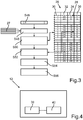
- Fig. 3 is used to illustrate the use of the camera 12 in the vehicle.
- the lookup-table 26 provided in a storage device 38 of the camera 12 (see Fig. 4 ) is accessed.
- adjustable parameters 27 of the camera 12 are checked in step S48, namely the preset gamma value and the preset integration time.
- a picture is captured in step S48.
- step S50 a portion 28 of the lookup-table 26, which is to be focussed on, is delimited with respect to the rest of the lookup-table 26.
- the preset gamma value and the preset integration time are present in this portion 28 of the lookup-table 26.
- the gamma values are listed in a first column 30 and the values for possible integration times in a second column 32 of the lookup-table 26.
- a greyscale value is determined for each pixel of the camera. Then, in step S52 the determined greyscale value is compared with brightness reference values indicated in greyscale values, which have been obtained in the calibration process beforehand.
- the brightness reference values are listed in another column 34 of the lookup-table 26.
- To each greyscale value in column 34 is assigned a corresponding value in lumen which is listed in another column 36 of the lookup-table 26.
- the corresponding value in lumen has also been obtained during the calibration process described above. Still in Step 52 to a pixel for which a certain greyscale value has been determined the corresponding value in lumen from column 36 is assigned.
- step S52 To each greyscale value of all the pixels of the picture taken by the camera 12 are assigned the corresponding values in lumen in step S52. Following that, in step S54 the values in lumen, which have been assigned to every single pixel of the picture based on its greyscale value, are summed up. Since the brightness usually is indicated in lumen per square meter, the sum of all values in lumen assigned to each one of the pixels is related to the total surface of all pixels of the camera in step S56. Thus, it is possible to determine the brightness of the camera's surroundings by using the greyscale values provided by the camera. The brightness is indicated in lux.
- the camera 12 which enables determining brightness can also be used as rain sensor.
- Fig. 4 shows, in a very schematical way, the camera 12, wherein the lookup-table 26 is arranged in a storage device 38 of the camera 12.
- an evaluation unit 40 of the camera 12 accesses the storage device 38 and thus makes it possible to compare the greyscale values determined by the camera 12 with the brightness reference values stored in column 34 of the lookup-table 26.
- the evaluation unit 40 also performs the summing up of the corresponding values in lumen assigned to the respective greyscale values and the transformation of the total luminous flux received by the pixels in illuminance, that is in lumen per square meter.
- the evaluation unit 40 therefore enables to give out the brightness value determined by the camera 12 in lux.
- the storage device 38 and/or the evaluation unit 40 can be units arranged outside the camera 12, for example in a control unit to which the camera 12 is coupled.
Landscapes
- Physics & Mathematics (AREA)
- General Physics & Mathematics (AREA)
- Engineering & Computer Science (AREA)
- Multimedia (AREA)
- Life Sciences & Earth Sciences (AREA)
- Sustainable Development (AREA)
- Spectroscopy & Molecular Physics (AREA)
- Signal Processing (AREA)
- Studio Devices (AREA)
- Mechanical Engineering (AREA)
Description
- The invention relates to a camera arrangement for a vehicle, comprising a camera. By means of the camera arrangement the brightness of the surroundings of the camera can be determined. Furthermore, the invention relates to a method for calibrating a camera for a vehicle and to a method for operating a camera arrangement.
- Document
FR 2 783 613 A1 - In
EP 1 790 541 A2 a system and method for detecting obstructions in a camera field of view is disclosed. - The published patent application
EP 1 389 878 A1 discloses a method for camera calibration. - In the patent application
US 2009/0160937 A1 , a camera control method for a vehicle entrance control systems is described. - Another conventional camera arrangement and camera control method is disclosed in
US 2011/0018973 . - It is known to use a camera with a picture sensor and with a photometer in a camera arrangement for a vehicle. The photometer records the brightness of the surroundings of the camera with brightness being the visual perception in which a source appears to be radiating or reflecting light. Thus it can, for example, be determined, if an area in front of the vehicle, the brightness of which is determined by the photometer, is a tunnel or not. If a tunnel is determined that way, corresponding functional units of the vehicle are activated. For instance the headlights may be switched on upon a tunnel coming within the capture range of the photometer.
- Such a photometer used in a camera arrangement for a vehicle usually also comprises a wavelength filter which lets through only the wavelengths perceivable by the human eye. The photometric quantity which is measured by the photometer is normally given in Energy per square centimeter. In vehicles the photometer is also used to detect rain so that windscreen wipers of the vehicle can be activated accordingly. Also the headlights can be activated when darkness comes up, that is in dependence on the brightness determined by the photometer.
- A camera known from the state of the art, which comprises a photometer is relatively complex.
- It is therefore the task of the present invention to create a simplified camera arrangement of the afore-mentioned kind, a method for calibrating a camera and a simplified method for operating a camera arrangement for a vehicle.
- This task is met by a camera arrangement with the features of
claim 3, a calibration method with the features of claim 1, and a method for operating a camera arrangement with the features of claim 2. Advantageous embodiments with convenient further developments of the invention are indicated in the dependent claims. - Thus, when operating the camera arrangement a brightness value determined by the camera is compared to the brightness reference value to which the corresponding value is assigned, while the corresponding value is indicative of the photometric quantity. Thus, the camera arrangement operates without a photometer. Brightness values determined by the camera can be directly used to indicate the brightness of the surroundings of the camera, which is usually determined by a photometer.
- While the photometer, known from the state of the art, captures the wavelengths perceivable by the human eye, the camera captures a luminous flux the spectrum of wavelengths of which exceeds the spectrum which can be perceived by the human eye. This is because camera usually do not comprise a wavelength filter like the photometer. Thus, without prior calibration with the photometer the total luminous flux determined by the camera cannot directly be used for indicating the brightness that can be perceived by the human eye.
- When operating the presently described camera arrangement the brightness value determined by the camera is compared to the reference value, to which the corresponding value measured by the photometer at the same brightness is assigned. For that, the camera is calibrated with the photometer beforehand. This calibration makes it possible to establish a correlation between the illuminance which the photometer indicates at a given the brightness and the value of brightness determined by the camera at the same brightness. Consequently there are values stored in the storage device, which correlate brightness values determined by the camera exposed to a certain luminous flux to values indicating the luminous flux as determined by a photometer.
- The storage device can be integrated into the camera. Alternatively the storage device can be integrated into a control device which can be coupled with the camera, and which is a separate component in the vehicle. The evaluation unit can be integrated into the camera as well, or else provided outside of the camera, particularly in the control device.
- In an advantageous embodiment of the invention the brightness which is determined by the camera arrangement takes into account brightness values determined per pixel in a picture captured by the camera. For this purpose the brightness values determined per pixel are assigned to the values indicating the corresponding photometric quantity through comparison with the brightness reference values stored in the storage device. The values indicating the photometric quantity can be summed up in order to obtain the luminous flux captured by all pixels of the camera. Since the size of a pixel is known as well as the number of pixels of the camera, the luminous flux per surface unit can be indicated in lux, as it is usually done by a photometer. The brightness value determined per pixel can be correlated very fast and easily with the value indicative of the photometric quantity.
- In a further advantageous embodiment of the invention at least two brightness reference values are stored in the storage device, wherein the reference values correspond to different gamma values of the camera. Certain cameras used in vehicle applications allow the so called gamma correction to be varied by pre-setting a gamma value within a range of gamma values. The gamma correction transforms an input quantity into an output quantity according to a certain rule, in order to convert a physically proportionally growing quantity to a quantity which the human sense does not perceive as growing linearly. A low preset gamma value of the camera leads to a relatively fast saturation of the pixels of the camera when brightness increases. The gamma value thus also reflects the response dynamics of the camera. Therefore with different gamma values and corresponding reference values stored in the storage device, a particularly precise detection of the brightness can be carried out.
- Alternatively, but preferably in addition, at least two brightness reference values are stored in the storage device, which correspond to different integration times of the camera. The integration time is the period of time during which a picture sensor of the camera accumulates charge carriers as the camera captures a picture. Storing different brightness reference values for different integration times is based on the finding that the luminous flux captured by the camera depends on the preset integration time. If the camera can be adjusted to different integration times, the consideration of the respective integration times allows for the determination of the brightness by utilization of the camera such as a photometer would do.
- An particularly fast and easy assignment of brightness reference values capturable by the camera to the corresponding values indicating the photometric quantity can be achieved, if, according to another advantageous embodiment of the invention, a plurality of such reference values are stored in a lookup-table provided in the storage device.
- In this case it has proven to be advantageous, if a portion of the lookup-table to be focussed on is pre-determined in dependence on a preset gamma value and/or on a preset integration time of the camera. Then not the whole lookup-table has to be scanned, but only the area of interest comprising the preset parameters. Thus the brightness can be determined particularly rapidly.
- It is furthermore preferred, if the photometric quantity is indicative of a brightness which can be perceived by the human eye. Thus, the brightness determined by the camera can be used to activate functional units of the vehicle, which are to be activated in case of decreased brightness as sensed by humans. It is thereby possible to activate the headlights of the vehicle, either on entering a tunnel with the vehicle or when dawn is approaching or under particularly dark skies.
- The at least one brightness reference value can be stored as a greyscale value. Such a greyscale value is readily available when a black and white camera is used. When using a digital colour camera (nowadays based on the use of an electronic sensor like CMOS or CCD) some conversion must be performed to determine greyscale values from the colour values. Different well known conversions exist and depend possibly on the image sensor used and/or the chosen weighting of the color channels.
- Finally, an angle of view capturable by an objective of the camera is preferably chosen around 40° as of classical camera. But wider angle of view could be conceivable like wider than 90°.
- The calibration process for calibrating a camera for a vehicle according to the invention is defined in independent Claim 1. It is thereby possible to refrain from providing a photometer in a vehicle, when using the camera arrangement comprising the camera and the storage device in order to determine the brightness of the camera's surroundings.
- It is preferred to store a plurality of brightness reference values together with the corresponding values in a lookup-table provided in the storage device. This makes it possible to use the calibration results in a particularly easy manner.
- In order to achieve a particularly reliable calibration, it is preferred to expose the camera and the photometer to the light source simultaneously.
- Furthermore, it is advantageous that when calibrating the camera with the photometer the same angles of field are used. For the camera this can be achieved by using an objective lens, while an appropriate diaphragm can be provided for the photometer. It can thereby be assured that the luminous flux emanating from the light source reaches the light sensitive elements of the photometer and the camera in the same way.
- The method for determining the brightness in a camera surrounding comprising a camera for a vehicle according to the invention is defined in independent Claim 2. Thus, it is possible to refrain from using a photometer when determining the brightness by means of the camera arrangement.
- It has proven to be advantageous, if the brightness reference value is obtained by a calibration method according to the invention.
- The preferred embodiments presented with respect to the camera arrangement according to the invention and the advantages thereof correspondingly apply to the methods according to the invention and vice versa.
- All of the features and feature combinations mentioned in the description above as well the features and feature combinations mentioned below in the description of the figures and/or shown in the figures alone are usable not only in the respectively specified combination, but also in other combinations or else alone without departing from the scope of the invention.
- The camera for carrying the process of claim 1 or the method of claim 2 is defined in
independent claim 3. - Further advantages, features and details of the invention are apparent from the claims, the following description of preferred embodiments as well as from the drawings. Therein show:
- Fig. 1
- a calibration device for calibrating a camera for a vehicle with a photometer;
- Fig. 2
- a flowchart for illustrating the calibration method;
- Fig. 3
- a flowchart for illustrating the determination of the brightness by means of the calibrated camera; and
- Fig. 4
- very schematically the camera comprising a storage device and an evaluation unit.
-
Fig. 1 shows acalibration device 10 for calibrating acamera 12 for a vehicle. Thecamera 12 and aphotometer 14 which is arranged next to thecamera 12 are arranged in achamber 16. Adiffusion filter 20 is arranged between alight source 18, thecamera 12 and thephotometer 14 which is located at the same distance from thediffusion filter 20 as thecamera 12. The whole backside of thediffusion filter 20 is evenly exposed to thelight source 18. Theluminous flux 22 emitting from thediffusion filter 20 is homogeneous on the entire surface of thediffusion filter 20, which faces towards thecamera 12 and thephotometer 14. - The
camera 12 can be a black and white camera and in particular comprise a CMOS sensor as picture sensor. Thecamera 12 can operate according to the VGA standard (VGA = Video Graphics Array). An objective lens of thecamera 12 provides for an angle of view of 40°. On the photometer 14 adiaphragm 24 provides for an angle of view of 40° as well. Thecamera 12 can comprise a filter, which lets wavelengths up to 650 nm pass. A bit-depth of thecamera 12 may be 12 bit. Other configurations for thecamera 12 and thephotometer 14 can be arranged for, provided that their parameters, for instance the number and the size of pixels of thecamera 12 as well as of the active surface of thephotometer 14 are known. - The
photometer 14 comprises a spectral filter so that the light sensitive elements of thephotometer 14 only detect those wavelengths which can be perceived by the human eye. Thecamera 12 which is intended to be used in vehicles, comprises no such spectral filter, so that it can meet other tasks in a better way, for instance detecting road markings, rain or tunnels. Furthermore, thecamera 12 can be designed for use at night or when the light conditions are poor. - When the
camera 12 and thephotometer 14 are exposed to theluminous flux 22 of thelight source 18, thephotometer 14 indicates the brightness in lux, that is lumen per square meter. Thecamera 12 captures aluminous flux 22 with a broader spectrum of wavelengths than the light perceivable by the human eye. Therefore from theluminous flux 22 captured by thecamera 12 it cannot directly be inferred to the brightness perceivable by the human eye. However, it depends on this brightness, if thecamera 12 is to be used to determine whether the vehicle comprising thecamera 12 enters a tunnel or if the headlights of the vehicle shall be automatically activated in other circumstances with decreasing brightness. - The
photometer 14 comprises optical and numerical correction devices to allow for consideration of the laws of photometry. For instance the spectral filter is provided, and the cosine emission law is taken into consideration when analyzing the signals provided by thephotometer 14. Through calibrating thecamera 12 with thephotometer 14 it is possible to refrain from providing such optical or numerical correction devices. The calibration also allows to ignore certain characteristics of thecamera 12, for instance the recording noise, the transmission and the wavelength spectrum which passes through the optical units of thecamera 12. - The
camera 12 can be parameterized, wherein the integration time as well as the gamma value can be adjusted. The integration time indicates during which time interval the photosensitive cells of the picture sensor of thecamera 12 are exposed to theluminous flux 22 in order to generate a certain electrical signal. The dynamic of the cameras' response can be adjusted by setting the gamma value. For instance, a low gamma value results in a quick saturation of the pixels of thecamera 12 when the brightness increases. - In the following an exemplary calculation is used to illustrate how the calibration of the
camera 12 with thephotometer 14 is carried out. With a luminous flux of 4 lumen and an active surface of thephotometer 14 of 0,002 m2 thephotometer 14 displays a brightness value of 2000 lux. Thecamera 12 is adjusted to a gamma value of 3 and an integration time of 243 lines. The integration time can be indicated in lines, provided thecamera 12 is a line camera, which means that the picture sensor only comprises one light sensitive line. Such a line camera provides, given a predetermined angle of view, a particularly good spatial resolution. Moreover, a line can be read by far more rapidly than an area. - As the
camera 12 requires a predetermined time for scanning a line, it is possible to use the integration time expressed in lines to indicate how many times the same line is scanned during capture of a picture. Multiple scanning of the same line is particularly expedient when there are strong differences in brightness within one line, as this avoids a saturation of the light sensitive cells of the picture sensor. Furthermore, it is thus possible to minimize the noise of the signal. - For a pixel of the
camera 12 regarded in the exemplary calculation a greyscale value of 1685 is determined. With a surface of a pixel of 3,6*10-11 m2 and 2000 lux (or 2000 lumen per square meter) this results in 7,2*10-8 lumen as photometric quantity. This value of the photometric quantity is therefore assigned to the greyscale value of 1685 as corresponding value. As already mentioned, this applies to an integration time of 243 lines and a gamma value of 3. Through varying the integration time, the gamma value and theluminous flux 22 emanating from thelight source 18, it is thus possible to assign values in lumen to every greyscale value determined by a pixel of thecamera 12. -
Fig. 2 is used to illustrate this calibration method. Thecamera 12 having a bit depth of 12 bit allows a graduation of 4096 greyscale values. The gamma value of thecamera 12 can, for instance, be variably adjusted between 0 and 15. The integration time of thecamera 12 can be varied between 0 and 486 lines. - During calibration, as shown in
Fig. 2 , after a starting step S10 the gamma value is set to a minimum in step S12. In step S14 the integration time is set to a minimum and in step S16 the intensity of alight source 18. In step S18 it is checked, whether the gamma value has reached its maximum. If this is not the case, it is checked in step S20, if the integration time has reached its maximum. If this is also not the case, it is checked in step S22, whether the intensity of thelight source 18 has reached its maximum. If this is not the case, thecamera 12 captures a picture in step S24. In step S26 a greyscale value for the picture is calculated. In thecalibration device 10 all pixels of thecamera 12 receive the same amount of light, but an average greyscale value is calculated in step S26. - In step S28 it is checked whether the greyscale value obtained in step S26 is less than the maximal greyscale value. If this is the case, a respective line is filled in a the lookup-table 26 (see
Fig. 3 ) in step S30. Afterwards, the light intensity of thelight source 18 is increased by one unit in step S32, and the procedure is continued with step S22. - If, however, it is determined in step S28 that the greyscale value has reached its maximum, the intensity of the
light source 18 is set to its maximum as well in step S34 and after that it is continued with step S22. Thus, it is determined in step S22 that thelight source 18 has reached its maximum intensity, and the intensity is set back to its minimum in step S36. - Following that the integration time is increased by one unit in step S38, for instance by one line or, if the integration time is indicated in milliseconds, by a fraction of a millisecond. Then, the procedure is continued with step S20. When the maximal integration time is reached, the integration time is set back to its minimum in step S40 after step S20. Following that, the gamma value is increased by one unit in step S42 and the procedure is continued with step S18. After reaching the maximum of the gamma value, the calibration is finished with step S44. Then the lookup-table is completely filled in.
- The lookup-table 26, of which a part is shown in
Fig. 3 , can then be used to assign respective values in lumen to the greyscale values determined for each of the pixels of thecamera 12. This enables determining the brightness of the surroundings of thecamera 12 by using thecamera 12. -
Fig. 3 is used to illustrate the use of thecamera 12 in the vehicle. In order to determine the brightness with thecamera 12, the lookup-table 26 provided in astorage device 38 of the camera 12 (seeFig. 4 ) is accessed. After a starting step S46adjustable parameters 27 of thecamera 12 are checked in step S48, namely the preset gamma value and the preset integration time. Furthermore, a picture is captured in step S48. In step S50 aportion 28 of the lookup-table 26, which is to be focussed on, is delimited with respect to the rest of the lookup-table 26. The preset gamma value and the preset integration time are present in thisportion 28 of the lookup-table 26. The gamma values are listed in afirst column 30 and the values for possible integration times in asecond column 32 of the lookup-table 26. - A greyscale value is determined for each pixel of the camera. Then, in step S52 the determined greyscale value is compared with brightness reference values indicated in greyscale values, which have been obtained in the calibration process beforehand. The brightness reference values are listed in another
column 34 of the lookup-table 26. To each greyscale value incolumn 34 is assigned a corresponding value in lumen which is listed in anothercolumn 36 of the lookup-table 26. The corresponding value in lumen has also been obtained during the calibration process described above. Still in Step 52 to a pixel for which a certain greyscale value has been determined the corresponding value in lumen fromcolumn 36 is assigned. For instance for a gamma value of 3, an integration time of 240 lines and a greyscale value of 140 a corresponding value in nanolumen of 77 is found in one line within theportion 28 of the lookup-table 26. This applies for a camera with a bit-depth of 8 bit. - To each greyscale value of all the pixels of the picture taken by the
camera 12 are assigned the corresponding values in lumen in step S52. Following that, in step S54 the values in lumen, which have been assigned to every single pixel of the picture based on its greyscale value, are summed up. Since the brightness usually is indicated in lumen per square meter, the sum of all values in lumen assigned to each one of the pixels is related to the total surface of all pixels of the camera in step S56. Thus, it is possible to determine the brightness of the camera's surroundings by using the greyscale values provided by the camera. The brightness is indicated in lux. - Even when using a lookup-table which only contains a few data values, it is possible to achieve a good accuracy after calibration of the
camera 12 with thephotometer 14. For example an average mistake of - 9 % with a standard deviation of 21 % can be obtained by using the calibratedcamera 12 to determine the brightness compared to directly using aphotometer 14 for determining the brightness. In other words, the calibratedcamera 12 gives out a value of 700 lux to 1120 lux for a value of 1000 lux measured by thephotometer 14. These results can be ameliorated tremendously, if the lookup-table 26 is completed as mentioned above. - When using the
camera 12 in a vehicle, it is thus possible to refrain from using aphotometer 14 for tunnel detection, which allows for reduced costs for the camera arrangement comprising thecamera 12 and thestorage device 38. Thecamera 12 which enables determining brightness can also be used as rain sensor. -
Fig. 4 shows, in a very schematical way, thecamera 12, wherein the lookup-table 26 is arranged in astorage device 38 of thecamera 12. While operating thecamera 12 anevaluation unit 40 of thecamera 12 accesses thestorage device 38 and thus makes it possible to compare the greyscale values determined by thecamera 12 with the brightness reference values stored incolumn 34 of the lookup-table 26. Theevaluation unit 40 also performs the summing up of the corresponding values in lumen assigned to the respective greyscale values and the transformation of the total luminous flux received by the pixels in illuminance, that is in lumen per square meter. Theevaluation unit 40 therefore enables to give out the brightness value determined by thecamera 12 in lux. - In an alternative camera arrangement the
storage device 38 and/or theevaluation unit 40 can be units arranged outside thecamera 12, for example in a control unit to which thecamera 12 is coupled.
Claims (3)
- Calibration process for a camera for a vehicle, comprising the following steps:- exposing a camera (12) and a photometer (14) to aluminous fluxes- determining for each of the pixels of the camera a value for an integration time (32), a gamma value (30), a value in lumen (36) and a grayscale value (36) when exposed to each of said luminous fluxes - recording said values in a lookup-table (26).
- Method for determining the brightness in a camera's surroundings comprising the following steps:- capturing a picture with the camera (12) for a vehicle of claim 1- determining for each pixel of said picture a grayscale value- assigning to each pixel a value in lumen corresponding to said grayscale value which correspondence has been obtained in a calibration process as claimed in claim 1- summing up the values in lumen for all pixels- determining as the brightness of the camera's surrounding the sum of said values.
- Camera (12) configured for carrying out the method according to claim 1 or claim 2.
Applications Claiming Priority (1)
| Application Number | Priority Date | Filing Date | Title |
|---|---|---|---|
| PCT/EP2011/057786 WO2012155951A1 (en) | 2011-05-13 | 2011-05-13 | Camera arrangement for a vehicle and method for calibrating a camera and for operating a camera arrangement |
Publications (2)
| Publication Number | Publication Date |
|---|---|
| EP2710340A1 EP2710340A1 (en) | 2014-03-26 |
| EP2710340B1 true EP2710340B1 (en) | 2019-04-03 |
Family
ID=44119059
Family Applications (1)
| Application Number | Title | Priority Date | Filing Date |
|---|---|---|---|
| EP11719817.6A Not-in-force EP2710340B1 (en) | 2011-05-13 | 2011-05-13 | Camera arrangement for a vehicle and method for calibrating a camera and for operating a camera arrangement |
Country Status (3)
| Country | Link |
|---|---|
| US (1) | US10079979B2 (en) |
| EP (1) | EP2710340B1 (en) |
| WO (1) | WO2012155951A1 (en) |
Families Citing this family (8)
| Publication number | Priority date | Publication date | Assignee | Title |
|---|---|---|---|---|
| US9900522B2 (en) | 2010-12-01 | 2018-02-20 | Magna Electronics Inc. | System and method of establishing a multi-camera image using pixel remapping |
| US9870704B2 (en) * | 2012-06-20 | 2018-01-16 | Conduent Business Services, Llc | Camera calibration application |
| JP6315239B2 (en) * | 2014-01-14 | 2018-04-25 | 株式会社リコー | Imaging apparatus, imaging method, image processing apparatus, imaging program |
| US9324146B2 (en) | 2014-06-16 | 2016-04-26 | Northwestern University | Photometric and radiometric calibration using optical feedback |
| CN105208360B (en) * | 2015-09-23 | 2017-07-25 | 青岛海信移动通信技术股份有限公司 | Image preview method, device and the terminal of a kind of intelligent terminal |
| JPWO2017110192A1 (en) * | 2015-12-24 | 2018-10-11 | ソニー株式会社 | Information processing apparatus, information processing method, program, and information processing system |
| US11115602B2 (en) * | 2019-06-11 | 2021-09-07 | Watchguard Video, Inc. | Emulating light sensitivity of a target |
| US11987172B1 (en) * | 2023-01-19 | 2024-05-21 | Plusai, Inc. | Automatic control of high beam operation |
Family Cites Families (20)
| Publication number | Priority date | Publication date | Assignee | Title |
|---|---|---|---|---|
| GB877336A (en) * | 1958-09-09 | 1961-09-13 | Robert Mcvitie Weston | Improvements in or relating to photographic cameras |
| US6930709B1 (en) * | 1997-12-04 | 2005-08-16 | Pentax Of America, Inc. | Integrated internet/intranet camera |
| JP3133985B2 (en) | 1998-08-12 | 2001-02-13 | 技研興業株式会社 | How to improve bottom quality of lakes and marshes |
| AUPQ212499A0 (en) * | 1999-08-10 | 1999-09-02 | Ajax Cooke Pty Ltd | Item recognition method and apparatus |
| US6308777B2 (en) * | 1999-10-13 | 2001-10-30 | Halliburton Energy Services, Inc. | Cementing wells with crack and shatter resistant cement |
| JP2004048345A (en) * | 2002-07-11 | 2004-02-12 | Niles Co Ltd | Imaging system |
| US7068302B2 (en) | 2002-08-15 | 2006-06-27 | Ford Global Technologies, Llc | Method for camera calibration and quality testing |
| JP4216021B2 (en) * | 2002-08-30 | 2009-01-28 | 富士重工業株式会社 | Intruder detection device |
| US20060140445A1 (en) * | 2004-03-22 | 2006-06-29 | Cusack Francis J Jr | Method and apparatus for capturing digital facial images optimally suited for manual and automated recognition |
| US7450754B2 (en) * | 2004-03-23 | 2008-11-11 | Microsoft Corporation | Radiometric calibration from a single image |
| US7751653B2 (en) * | 2004-05-13 | 2010-07-06 | Color Savvy Systems Limited | Method for collecting data for color measurements from a digital electronic image capturing device or system |
| DE102006016073A1 (en) * | 2005-08-24 | 2007-03-22 | Dr.Ing.H.C. F. Porsche Ag | Method for controlling the headlamp range of a motor vehicle |
| US8553088B2 (en) | 2005-11-23 | 2013-10-08 | Mobileye Technologies Limited | Systems and methods for detecting obstructions in a camera field of view |
| US20070132873A1 (en) * | 2005-12-08 | 2007-06-14 | Fujifilm Corporation | Portable instrument and digital camera |
| JP2009146259A (en) * | 2007-12-17 | 2009-07-02 | Toshiba Corp | Vehicle number photographing system, vehicle number photographing method |
| EP2073035A1 (en) * | 2007-12-18 | 2009-06-24 | IEE INTERNATIONAL ELECTRONICS & ENGINEERING S.A. | Recording of 3D images of a scene |
| KR100950465B1 (en) | 2007-12-21 | 2010-03-31 | 손승남 | Camera Control Method for Vehicle Access Control System |
| JP5040776B2 (en) * | 2008-03-31 | 2012-10-03 | アイシン精機株式会社 | Imaging device |
| JP4555876B2 (en) | 2008-05-30 | 2010-10-06 | 株式会社日本自動車部品総合研究所 | Car camera calibration method |
| US8941706B2 (en) * | 2010-04-07 | 2015-01-27 | Apple Inc. | Image processing for a dual camera mobile device |
-
2011
- 2011-05-13 US US14/117,563 patent/US10079979B2/en active Active
- 2011-05-13 EP EP11719817.6A patent/EP2710340B1/en not_active Not-in-force
- 2011-05-13 WO PCT/EP2011/057786 patent/WO2012155951A1/en not_active Ceased
Non-Patent Citations (1)
| Title |
|---|
| None * |
Also Published As
| Publication number | Publication date |
|---|---|
| WO2012155951A1 (en) | 2012-11-22 |
| US10079979B2 (en) | 2018-09-18 |
| EP2710340A1 (en) | 2014-03-26 |
| US20150109445A1 (en) | 2015-04-23 |
Similar Documents
| Publication | Publication Date | Title |
|---|---|---|
| US10079979B2 (en) | Camera arrangement for a vehicle and method for calibrating a camera and for operating a camera arrangement | |
| US11405535B2 (en) | Quad color filter array camera sensor configurations | |
| US10419685B2 (en) | Image processing apparatus, image processing method, and computer-readable recording medium | |
| US9230310B2 (en) | Imaging systems and methods for location-specific image flare mitigation | |
| US9071762B2 (en) | Image sensor including real-time automatic exposure control and swallowable pill including the same | |
| US9787911B2 (en) | Systems and methods for photometric normalization in array cameras | |
| US8199229B2 (en) | Color filter, image processing apparatus, image processing method, image-capture apparatus, image-capture method, program and recording medium | |
| US8767117B2 (en) | Imaging device and method to correct the focus detection pixels using peripheral standard pixels and correcting defective peripheral standard pixels as well if found | |
| US10416026B2 (en) | Image processing apparatus for correcting pixel value based on difference between spectral sensitivity characteristic of pixel of interest and reference spectral sensitivity, image processing method, and computer-readable recording medium | |
| TWI448153B (en) | Multi-array sensor with integrated sub-array for parallax detection and photometer functionality | |
| US8013907B2 (en) | System and method for adaptive local white balance adjustment | |
| US20070177004A1 (en) | Image creating method and imaging device | |
| US20160057332A1 (en) | Systems and Methods for High Dynamic Range Imaging Using Array Cameras | |
| KR102368597B1 (en) | Image photographing apparatus and method of controlling thereof | |
| US10887527B2 (en) | Image capture apparatus having illumination section, monitoring system including image capture apparatus, method of controlling image capture apparatus, and storage medium | |
| US20100066857A1 (en) | Methods, systems and apparatuses for white balance calibration | |
| US20090116829A1 (en) | Method and apparatus of determining the best focus position of a lens | |
| US7990426B2 (en) | Phase adjusting device and digital camera | |
| FR3091114A1 (en) | image capture device and associated driver monitoring system | |
| JP2012010282A (en) | Imaging device, exposure control method, and exposure control program | |
| JP2011087136A (en) | Imaging apparatus and imaging system | |
| JP2004229034A (en) | Day/night camera incorporating infrared illumination | |
| JP2017038311A (en) | Solid-state imaging device | |
| JP6712886B2 (en) | Imaging device, imaging method, and vehicle | |
| JP2017220811A (en) | Imaging apparatus and camera system |
Legal Events
| Date | Code | Title | Description |
|---|---|---|---|
| PUAI | Public reference made under article 153(3) epc to a published international application that has entered the european phase |
Free format text: ORIGINAL CODE: 0009012 |
|
| 17P | Request for examination filed |
Effective date: 20131204 |
|
| AK | Designated contracting states |
Kind code of ref document: A1 Designated state(s): AL AT BE BG CH CY CZ DE DK EE ES FI FR GB GR HR HU IE IS IT LI LT LU LV MC MK MT NL NO PL PT RO RS SE SI SK SM TR |
|
| DAX | Request for extension of the european patent (deleted) | ||
| RIN1 | Information on inventor provided before grant (corrected) |
Inventor name: QUELQUEJAY, YAN Inventor name: WEDAJO, BROUK Inventor name: AHIAD, SAMIA Inventor name: ROBERT, CAROLINE Inventor name: PETIT, JULIA |
|
| 17Q | First examination report despatched |
Effective date: 20150211 |
|
| REG | Reference to a national code |
Ref country code: DE Ref legal event code: R079 Ref document number: 602011057733 Country of ref document: DE Free format text: PREVIOUS MAIN CLASS: G01J0001000000 Ipc: G03B0007080000 |
|
| RIC1 | Information provided on ipc code assigned before grant |
Ipc: G03B 43/00 20060101ALI20160711BHEP Ipc: H04N 17/00 20060101ALI20160711BHEP Ipc: B60R 1/00 20060101ALI20160711BHEP Ipc: G01J 1/42 20060101ALI20160711BHEP Ipc: H04N 5/235 20060101ALI20160711BHEP Ipc: G03B 17/18 20060101ALI20160711BHEP Ipc: G03B 7/08 20060101AFI20160711BHEP |
|
| GRAP | Despatch of communication of intention to grant a patent |
Free format text: ORIGINAL CODE: EPIDOSNIGR1 |
|
| INTG | Intention to grant announced |
Effective date: 20160830 |
|
| GRAJ | Information related to disapproval of communication of intention to grant by the applicant or resumption of examination proceedings by the epo deleted |
Free format text: ORIGINAL CODE: EPIDOSDIGR1 |
|
| STAA | Information on the status of an ep patent application or granted ep patent |
Free format text: STATUS: EXAMINATION IS IN PROGRESS |
|
| INTC | Intention to grant announced (deleted) | ||
| GRAP | Despatch of communication of intention to grant a patent |
Free format text: ORIGINAL CODE: EPIDOSNIGR1 |
|
| STAA | Information on the status of an ep patent application or granted ep patent |
Free format text: STATUS: GRANT OF PATENT IS INTENDED |
|
| INTG | Intention to grant announced |
Effective date: 20181024 |
|
| GRAS | Grant fee paid |
Free format text: ORIGINAL CODE: EPIDOSNIGR3 |
|
| GRAA | (expected) grant |
Free format text: ORIGINAL CODE: 0009210 |
|
| STAA | Information on the status of an ep patent application or granted ep patent |
Free format text: STATUS: THE PATENT HAS BEEN GRANTED |
|
| AK | Designated contracting states |
Kind code of ref document: B1 Designated state(s): AL AT BE BG CH CY CZ DE DK EE ES FI FR GB GR HR HU IE IS IT LI LT LU LV MC MK MT NL NO PL PT RO RS SE SI SK SM TR |
|
| REG | Reference to a national code |
Ref country code: GB Ref legal event code: FG4D |
|
| REG | Reference to a national code |
Ref country code: CH Ref legal event code: EP Ref country code: AT Ref legal event code: REF Ref document number: 1116475 Country of ref document: AT Kind code of ref document: T Effective date: 20190415 |
|
| REG | Reference to a national code |
Ref country code: DE Ref legal event code: R096 Ref document number: 602011057733 Country of ref document: DE |
|
| REG | Reference to a national code |
Ref country code: IE Ref legal event code: FG4D |
|
| REG | Reference to a national code |
Ref country code: NL Ref legal event code: MP Effective date: 20190403 |
|
| REG | Reference to a national code |
Ref country code: LT Ref legal event code: MG4D |
|
| REG | Reference to a national code |
Ref country code: AT Ref legal event code: MK05 Ref document number: 1116475 Country of ref document: AT Kind code of ref document: T Effective date: 20190403 |
|
| PG25 | Lapsed in a contracting state [announced via postgrant information from national office to epo] |
Ref country code: NL Free format text: LAPSE BECAUSE OF FAILURE TO SUBMIT A TRANSLATION OF THE DESCRIPTION OR TO PAY THE FEE WITHIN THE PRESCRIBED TIME-LIMIT Effective date: 20190403 |
|
| PG25 | Lapsed in a contracting state [announced via postgrant information from national office to epo] |
Ref country code: AL Free format text: LAPSE BECAUSE OF FAILURE TO SUBMIT A TRANSLATION OF THE DESCRIPTION OR TO PAY THE FEE WITHIN THE PRESCRIBED TIME-LIMIT Effective date: 20190403 Ref country code: PT Free format text: LAPSE BECAUSE OF FAILURE TO SUBMIT A TRANSLATION OF THE DESCRIPTION OR TO PAY THE FEE WITHIN THE PRESCRIBED TIME-LIMIT Effective date: 20190803 Ref country code: ES Free format text: LAPSE BECAUSE OF FAILURE TO SUBMIT A TRANSLATION OF THE DESCRIPTION OR TO PAY THE FEE WITHIN THE PRESCRIBED TIME-LIMIT Effective date: 20190403 Ref country code: CZ Free format text: LAPSE BECAUSE OF FAILURE TO SUBMIT A TRANSLATION OF THE DESCRIPTION OR TO PAY THE FEE WITHIN THE PRESCRIBED TIME-LIMIT Effective date: 20190403 Ref country code: SE Free format text: LAPSE BECAUSE OF FAILURE TO SUBMIT A TRANSLATION OF THE DESCRIPTION OR TO PAY THE FEE WITHIN THE PRESCRIBED TIME-LIMIT Effective date: 20190403 Ref country code: HR Free format text: LAPSE BECAUSE OF FAILURE TO SUBMIT A TRANSLATION OF THE DESCRIPTION OR TO PAY THE FEE WITHIN THE PRESCRIBED TIME-LIMIT Effective date: 20190403 Ref country code: NO Free format text: LAPSE BECAUSE OF FAILURE TO SUBMIT A TRANSLATION OF THE DESCRIPTION OR TO PAY THE FEE WITHIN THE PRESCRIBED TIME-LIMIT Effective date: 20190703 Ref country code: FI Free format text: LAPSE BECAUSE OF FAILURE TO SUBMIT A TRANSLATION OF THE DESCRIPTION OR TO PAY THE FEE WITHIN THE PRESCRIBED TIME-LIMIT Effective date: 20190403 Ref country code: LT Free format text: LAPSE BECAUSE OF FAILURE TO SUBMIT A TRANSLATION OF THE DESCRIPTION OR TO PAY THE FEE WITHIN THE PRESCRIBED TIME-LIMIT Effective date: 20190403 |
|
| PG25 | Lapsed in a contracting state [announced via postgrant information from national office to epo] |
Ref country code: RS Free format text: LAPSE BECAUSE OF FAILURE TO SUBMIT A TRANSLATION OF THE DESCRIPTION OR TO PAY THE FEE WITHIN THE PRESCRIBED TIME-LIMIT Effective date: 20190403 Ref country code: LV Free format text: LAPSE BECAUSE OF FAILURE TO SUBMIT A TRANSLATION OF THE DESCRIPTION OR TO PAY THE FEE WITHIN THE PRESCRIBED TIME-LIMIT Effective date: 20190403 Ref country code: PL Free format text: LAPSE BECAUSE OF FAILURE TO SUBMIT A TRANSLATION OF THE DESCRIPTION OR TO PAY THE FEE WITHIN THE PRESCRIBED TIME-LIMIT Effective date: 20190403 Ref country code: BG Free format text: LAPSE BECAUSE OF FAILURE TO SUBMIT A TRANSLATION OF THE DESCRIPTION OR TO PAY THE FEE WITHIN THE PRESCRIBED TIME-LIMIT Effective date: 20190703 Ref country code: GR Free format text: LAPSE BECAUSE OF FAILURE TO SUBMIT A TRANSLATION OF THE DESCRIPTION OR TO PAY THE FEE WITHIN THE PRESCRIBED TIME-LIMIT Effective date: 20190704 |
|
| REG | Reference to a national code |
Ref country code: CH Ref legal event code: PL |
|
| PG25 | Lapsed in a contracting state [announced via postgrant information from national office to epo] |
Ref country code: IS Free format text: LAPSE BECAUSE OF FAILURE TO SUBMIT A TRANSLATION OF THE DESCRIPTION OR TO PAY THE FEE WITHIN THE PRESCRIBED TIME-LIMIT Effective date: 20190803 Ref country code: AT Free format text: LAPSE BECAUSE OF FAILURE TO SUBMIT A TRANSLATION OF THE DESCRIPTION OR TO PAY THE FEE WITHIN THE PRESCRIBED TIME-LIMIT Effective date: 20190403 |
|
| REG | Reference to a national code |
Ref country code: DE Ref legal event code: R097 Ref document number: 602011057733 Country of ref document: DE |
|
| PG25 | Lapsed in a contracting state [announced via postgrant information from national office to epo] |
Ref country code: MC Free format text: LAPSE BECAUSE OF FAILURE TO SUBMIT A TRANSLATION OF THE DESCRIPTION OR TO PAY THE FEE WITHIN THE PRESCRIBED TIME-LIMIT Effective date: 20190403 Ref country code: LI Free format text: LAPSE BECAUSE OF NON-PAYMENT OF DUE FEES Effective date: 20190531 Ref country code: DK Free format text: LAPSE BECAUSE OF FAILURE TO SUBMIT A TRANSLATION OF THE DESCRIPTION OR TO PAY THE FEE WITHIN THE PRESCRIBED TIME-LIMIT Effective date: 20190403 Ref country code: SK Free format text: LAPSE BECAUSE OF FAILURE TO SUBMIT A TRANSLATION OF THE DESCRIPTION OR TO PAY THE FEE WITHIN THE PRESCRIBED TIME-LIMIT Effective date: 20190403 Ref country code: EE Free format text: LAPSE BECAUSE OF FAILURE TO SUBMIT A TRANSLATION OF THE DESCRIPTION OR TO PAY THE FEE WITHIN THE PRESCRIBED TIME-LIMIT Effective date: 20190403 Ref country code: RO Free format text: LAPSE BECAUSE OF FAILURE TO SUBMIT A TRANSLATION OF THE DESCRIPTION OR TO PAY THE FEE WITHIN THE PRESCRIBED TIME-LIMIT Effective date: 20190403 Ref country code: CH Free format text: LAPSE BECAUSE OF NON-PAYMENT OF DUE FEES Effective date: 20190531 |
|
| REG | Reference to a national code |
Ref country code: BE Ref legal event code: MM Effective date: 20190531 |
|
| PLBE | No opposition filed within time limit |
Free format text: ORIGINAL CODE: 0009261 |
|
| STAA | Information on the status of an ep patent application or granted ep patent |
Free format text: STATUS: NO OPPOSITION FILED WITHIN TIME LIMIT |
|
| PG25 | Lapsed in a contracting state [announced via postgrant information from national office to epo] |
Ref country code: LU Free format text: LAPSE BECAUSE OF NON-PAYMENT OF DUE FEES Effective date: 20190513 Ref country code: SM Free format text: LAPSE BECAUSE OF FAILURE TO SUBMIT A TRANSLATION OF THE DESCRIPTION OR TO PAY THE FEE WITHIN THE PRESCRIBED TIME-LIMIT Effective date: 20190403 Ref country code: IT Free format text: LAPSE BECAUSE OF FAILURE TO SUBMIT A TRANSLATION OF THE DESCRIPTION OR TO PAY THE FEE WITHIN THE PRESCRIBED TIME-LIMIT Effective date: 20190403 |
|
| 26N | No opposition filed |
Effective date: 20200106 |
|
| PG25 | Lapsed in a contracting state [announced via postgrant information from national office to epo] |
Ref country code: TR Free format text: LAPSE BECAUSE OF FAILURE TO SUBMIT A TRANSLATION OF THE DESCRIPTION OR TO PAY THE FEE WITHIN THE PRESCRIBED TIME-LIMIT Effective date: 20190403 |
|
| PG25 | Lapsed in a contracting state [announced via postgrant information from national office to epo] |
Ref country code: IE Free format text: LAPSE BECAUSE OF NON-PAYMENT OF DUE FEES Effective date: 20190513 |
|
| PG25 | Lapsed in a contracting state [announced via postgrant information from national office to epo] |
Ref country code: BE Free format text: LAPSE BECAUSE OF NON-PAYMENT OF DUE FEES Effective date: 20190531 Ref country code: SI Free format text: LAPSE BECAUSE OF FAILURE TO SUBMIT A TRANSLATION OF THE DESCRIPTION OR TO PAY THE FEE WITHIN THE PRESCRIBED TIME-LIMIT Effective date: 20190403 |
|
| PG25 | Lapsed in a contracting state [announced via postgrant information from national office to epo] |
Ref country code: CY Free format text: LAPSE BECAUSE OF FAILURE TO SUBMIT A TRANSLATION OF THE DESCRIPTION OR TO PAY THE FEE WITHIN THE PRESCRIBED TIME-LIMIT Effective date: 20190403 |
|
| PG25 | Lapsed in a contracting state [announced via postgrant information from national office to epo] |
Ref country code: MT Free format text: LAPSE BECAUSE OF FAILURE TO SUBMIT A TRANSLATION OF THE DESCRIPTION OR TO PAY THE FEE WITHIN THE PRESCRIBED TIME-LIMIT Effective date: 20190403 Ref country code: HU Free format text: LAPSE BECAUSE OF FAILURE TO SUBMIT A TRANSLATION OF THE DESCRIPTION OR TO PAY THE FEE WITHIN THE PRESCRIBED TIME-LIMIT; INVALID AB INITIO Effective date: 20110513 |
|
| PG25 | Lapsed in a contracting state [announced via postgrant information from national office to epo] |
Ref country code: MK Free format text: LAPSE BECAUSE OF FAILURE TO SUBMIT A TRANSLATION OF THE DESCRIPTION OR TO PAY THE FEE WITHIN THE PRESCRIBED TIME-LIMIT Effective date: 20190403 |
|
| P01 | Opt-out of the competence of the unified patent court (upc) registered |
Effective date: 20230528 |
|
| PGFP | Annual fee paid to national office [announced via postgrant information from national office to epo] |
Ref country code: GB Payment date: 20240523 Year of fee payment: 14 |
|
| PGFP | Annual fee paid to national office [announced via postgrant information from national office to epo] |
Ref country code: DE Payment date: 20240513 Year of fee payment: 14 |
|
| PGFP | Annual fee paid to national office [announced via postgrant information from national office to epo] |
Ref country code: FR Payment date: 20240524 Year of fee payment: 14 |
|
| REG | Reference to a national code |
Ref country code: DE Ref legal event code: R119 Ref document number: 602011057733 Country of ref document: DE |
|
| GBPC | Gb: european patent ceased through non-payment of renewal fee |
Effective date: 20250513 |
|
| PG25 | Lapsed in a contracting state [announced via postgrant information from national office to epo] |
Ref country code: GB Free format text: LAPSE BECAUSE OF NON-PAYMENT OF DUE FEES Effective date: 20250513 |
|
| PG25 | Lapsed in a contracting state [announced via postgrant information from national office to epo] |
Ref country code: DE Free format text: LAPSE BECAUSE OF NON-PAYMENT OF DUE FEES Effective date: 20251202 |
|
| PG25 | Lapsed in a contracting state [announced via postgrant information from national office to epo] |
Ref country code: FR Free format text: LAPSE BECAUSE OF NON-PAYMENT OF DUE FEES Effective date: 20250531 |