EP2709957B1 - Desalination method - Google Patents
Desalination method Download PDFInfo
- Publication number
- EP2709957B1 EP2709957B1 EP12785549.2A EP12785549A EP2709957B1 EP 2709957 B1 EP2709957 B1 EP 2709957B1 EP 12785549 A EP12785549 A EP 12785549A EP 2709957 B1 EP2709957 B1 EP 2709957B1
- Authority
- EP
- European Patent Office
- Prior art keywords
- saltwater
- flow
- freshwater
- pump
- vaporization
- Prior art date
- Legal status (The legal status is an assumption and is not a legal conclusion. Google has not performed a legal analysis and makes no representation as to the accuracy of the status listed.)
- Active
Links
- 238000010612 desalination reaction Methods 0.000 title claims description 148
- 238000000034 method Methods 0.000 title claims description 51
- 230000008016 vaporization Effects 0.000 claims description 120
- 238000009834 vaporization Methods 0.000 claims description 114
- 239000013505 freshwater Substances 0.000 claims description 89
- XLYOFNOQVPJJNP-UHFFFAOYSA-N water Substances O XLYOFNOQVPJJNP-UHFFFAOYSA-N 0.000 claims description 56
- 238000011144 upstream manufacturing Methods 0.000 claims description 35
- 239000007788 liquid Substances 0.000 claims description 32
- 238000009833 condensation Methods 0.000 claims description 19
- 230000005494 condensation Effects 0.000 claims description 19
- 238000005086 pumping Methods 0.000 claims description 9
- 238000003860 storage Methods 0.000 claims description 8
- 239000012267 brine Substances 0.000 description 55
- HPALAKNZSZLMCH-UHFFFAOYSA-M sodium;chloride;hydrate Chemical compound O.[Na+].[Cl-] HPALAKNZSZLMCH-UHFFFAOYSA-M 0.000 description 55
- 239000003570 air Substances 0.000 description 44
- 239000013535 sea water Substances 0.000 description 35
- 230000008569 process Effects 0.000 description 27
- 238000005192 partition Methods 0.000 description 26
- 230000006835 compression Effects 0.000 description 13
- 238000007906 compression Methods 0.000 description 13
- 230000008901 benefit Effects 0.000 description 12
- 238000013461 design Methods 0.000 description 12
- 239000012530 fluid Substances 0.000 description 11
- 239000012528 membrane Substances 0.000 description 10
- 150000003839 salts Chemical class 0.000 description 10
- 238000005516 engineering process Methods 0.000 description 8
- 239000000203 mixture Substances 0.000 description 7
- 238000009835 boiling Methods 0.000 description 6
- 239000012080 ambient air Substances 0.000 description 5
- 239000007789 gas Substances 0.000 description 5
- 238000010438 heat treatment Methods 0.000 description 5
- 239000000243 solution Substances 0.000 description 5
- 230000004888 barrier function Effects 0.000 description 4
- 238000001704 evaporation Methods 0.000 description 4
- 230000008020 evaporation Effects 0.000 description 4
- 238000002360 preparation method Methods 0.000 description 4
- 230000007704 transition Effects 0.000 description 4
- 238000002203 pretreatment Methods 0.000 description 3
- 238000004513 sizing Methods 0.000 description 3
- IJGRMHOSHXDMSA-UHFFFAOYSA-N Atomic nitrogen Chemical compound N#N IJGRMHOSHXDMSA-UHFFFAOYSA-N 0.000 description 2
- 238000012935 Averaging Methods 0.000 description 2
- 230000009172 bursting Effects 0.000 description 2
- 230000008859 change Effects 0.000 description 2
- 238000006243 chemical reaction Methods 0.000 description 2
- 239000007795 chemical reaction product Substances 0.000 description 2
- 238000007599 discharging Methods 0.000 description 2
- 230000000694 effects Effects 0.000 description 2
- 229920001903 high density polyethylene Polymers 0.000 description 2
- 239000004700 high-density polyethylene Substances 0.000 description 2
- 239000000463 material Substances 0.000 description 2
- 230000007246 mechanism Effects 0.000 description 2
- 238000000926 separation method Methods 0.000 description 2
- XZPVPNZTYPUODG-UHFFFAOYSA-M sodium;chloride;dihydrate Chemical compound O.O.[Na+].[Cl-] XZPVPNZTYPUODG-UHFFFAOYSA-M 0.000 description 2
- 230000002459 sustained effect Effects 0.000 description 2
- 0 CI*1*CCCC1 Chemical compound CI*1*CCCC1 0.000 description 1
- 206010035148 Plague Diseases 0.000 description 1
- 241000607479 Yersinia pestis Species 0.000 description 1
- 230000002411 adverse Effects 0.000 description 1
- QVGXLLKOCUKJST-UHFFFAOYSA-N atomic oxygen Chemical compound [O] QVGXLLKOCUKJST-UHFFFAOYSA-N 0.000 description 1
- 230000009286 beneficial effect Effects 0.000 description 1
- 239000003638 chemical reducing agent Substances 0.000 description 1
- 238000004140 cleaning Methods 0.000 description 1
- 150000001875 compounds Chemical class 0.000 description 1
- 230000001419 dependent effect Effects 0.000 description 1
- 238000011161 development Methods 0.000 description 1
- 230000003292 diminished effect Effects 0.000 description 1
- 238000009826 distribution Methods 0.000 description 1
- 239000011152 fibreglass Substances 0.000 description 1
- -1 for example Substances 0.000 description 1
- 238000004519 manufacturing process Methods 0.000 description 1
- 229910052757 nitrogen Inorganic materials 0.000 description 1
- 239000001301 oxygen Substances 0.000 description 1
- 229910052760 oxygen Inorganic materials 0.000 description 1
- 239000004800 polyvinyl chloride Substances 0.000 description 1
- 230000037452 priming Effects 0.000 description 1
- 238000012545 processing Methods 0.000 description 1
- 239000000047 product Substances 0.000 description 1
- 230000000135 prohibitive effect Effects 0.000 description 1
- 238000004064 recycling Methods 0.000 description 1
- 230000001020 rhythmical effect Effects 0.000 description 1
- 229910001220 stainless steel Inorganic materials 0.000 description 1
- 239000010935 stainless steel Substances 0.000 description 1
Images


Classifications
-
- C—CHEMISTRY; METALLURGY
- C01—INORGANIC CHEMISTRY
- C01B—NON-METALLIC ELEMENTS; COMPOUNDS THEREOF; METALLOIDS OR COMPOUNDS THEREOF NOT COVERED BY SUBCLASS C01C
- C01B5/00—Water
-
- B—PERFORMING OPERATIONS; TRANSPORTING
- B01—PHYSICAL OR CHEMICAL PROCESSES OR APPARATUS IN GENERAL
- B01D—SEPARATION
- B01D3/00—Distillation or related exchange processes in which liquids are contacted with gaseous media, e.g. stripping
- B01D3/06—Flash distillation
-
- B—PERFORMING OPERATIONS; TRANSPORTING
- B01—PHYSICAL OR CHEMICAL PROCESSES OR APPARATUS IN GENERAL
- B01D—SEPARATION
- B01D3/00—Distillation or related exchange processes in which liquids are contacted with gaseous media, e.g. stripping
- B01D3/10—Vacuum distillation
- B01D3/106—Vacuum distillation with the use of a pump for creating vacuum and for removing the distillate
-
- B—PERFORMING OPERATIONS; TRANSPORTING
- B01—PHYSICAL OR CHEMICAL PROCESSES OR APPARATUS IN GENERAL
- B01D—SEPARATION
- B01D5/00—Condensation of vapours; Recovering volatile solvents by condensation
- B01D5/0033—Other features
- B01D5/0039—Recuperation of heat, e.g. use of heat pump(s), compression
-
- B—PERFORMING OPERATIONS; TRANSPORTING
- B01—PHYSICAL OR CHEMICAL PROCESSES OR APPARATUS IN GENERAL
- B01D—SEPARATION
- B01D5/00—Condensation of vapours; Recovering volatile solvents by condensation
- B01D5/0057—Condensation of vapours; Recovering volatile solvents by condensation in combination with other processes
- B01D5/006—Condensation of vapours; Recovering volatile solvents by condensation in combination with other processes with evaporation or distillation
-
- C—CHEMISTRY; METALLURGY
- C02—TREATMENT OF WATER, WASTE WATER, SEWAGE, OR SLUDGE
- C02F—TREATMENT OF WATER, WASTE WATER, SEWAGE, OR SLUDGE
- C02F1/00—Treatment of water, waste water, or sewage
- C02F1/02—Treatment of water, waste water, or sewage by heating
- C02F1/04—Treatment of water, waste water, or sewage by heating by distillation or evaporation
- C02F1/048—Purification of waste water by evaporation
-
- F—MECHANICAL ENGINEERING; LIGHTING; HEATING; WEAPONS; BLASTING
- F04—POSITIVE - DISPLACEMENT MACHINES FOR LIQUIDS; PUMPS FOR LIQUIDS OR ELASTIC FLUIDS
- F04B—POSITIVE-DISPLACEMENT MACHINES FOR LIQUIDS; PUMPS
- F04B15/00—Pumps adapted to handle specific fluids, e.g. by selection of specific materials for pumps or pump parts
-
- C—CHEMISTRY; METALLURGY
- C02—TREATMENT OF WATER, WASTE WATER, SEWAGE, OR SLUDGE
- C02F—TREATMENT OF WATER, WASTE WATER, SEWAGE, OR SLUDGE
- C02F2103/00—Nature of the water, waste water, sewage or sludge to be treated
- C02F2103/08—Seawater, e.g. for desalination
-
- Y—GENERAL TAGGING OF NEW TECHNOLOGICAL DEVELOPMENTS; GENERAL TAGGING OF CROSS-SECTIONAL TECHNOLOGIES SPANNING OVER SEVERAL SECTIONS OF THE IPC; TECHNICAL SUBJECTS COVERED BY FORMER USPC CROSS-REFERENCE ART COLLECTIONS [XRACs] AND DIGESTS
- Y02—TECHNOLOGIES OR APPLICATIONS FOR MITIGATION OR ADAPTATION AGAINST CLIMATE CHANGE
- Y02A—TECHNOLOGIES FOR ADAPTATION TO CLIMATE CHANGE
- Y02A20/00—Water conservation; Efficient water supply; Efficient water use
- Y02A20/124—Water desalination
- Y02A20/131—Reverse-osmosis
-
- Y—GENERAL TAGGING OF NEW TECHNOLOGICAL DEVELOPMENTS; GENERAL TAGGING OF CROSS-SECTIONAL TECHNOLOGIES SPANNING OVER SEVERAL SECTIONS OF THE IPC; TECHNICAL SUBJECTS COVERED BY FORMER USPC CROSS-REFERENCE ART COLLECTIONS [XRACs] AND DIGESTS
- Y02—TECHNOLOGIES OR APPLICATIONS FOR MITIGATION OR ADAPTATION AGAINST CLIMATE CHANGE
- Y02P—CLIMATE CHANGE MITIGATION TECHNOLOGIES IN THE PRODUCTION OR PROCESSING OF GOODS
- Y02P20/00—Technologies relating to chemical industry
- Y02P20/10—Process efficiency
-
- Y—GENERAL TAGGING OF NEW TECHNOLOGICAL DEVELOPMENTS; GENERAL TAGGING OF CROSS-SECTIONAL TECHNOLOGIES SPANNING OVER SEVERAL SECTIONS OF THE IPC; TECHNICAL SUBJECTS COVERED BY FORMER USPC CROSS-REFERENCE ART COLLECTIONS [XRACs] AND DIGESTS
- Y02—TECHNOLOGIES OR APPLICATIONS FOR MITIGATION OR ADAPTATION AGAINST CLIMATE CHANGE
- Y02P—CLIMATE CHANGE MITIGATION TECHNOLOGIES IN THE PRODUCTION OR PROCESSING OF GOODS
- Y02P20/00—Technologies relating to chemical industry
- Y02P20/50—Improvements relating to the production of bulk chemicals
-
- Y—GENERAL TAGGING OF NEW TECHNOLOGICAL DEVELOPMENTS; GENERAL TAGGING OF CROSS-SECTIONAL TECHNOLOGIES SPANNING OVER SEVERAL SECTIONS OF THE IPC; TECHNICAL SUBJECTS COVERED BY FORMER USPC CROSS-REFERENCE ART COLLECTIONS [XRACs] AND DIGESTS
- Y02—TECHNOLOGIES OR APPLICATIONS FOR MITIGATION OR ADAPTATION AGAINST CLIMATE CHANGE
- Y02P—CLIMATE CHANGE MITIGATION TECHNOLOGIES IN THE PRODUCTION OR PROCESSING OF GOODS
- Y02P70/00—Climate change mitigation technologies in the production process for final industrial or consumer products
- Y02P70/10—Greenhouse gas [GHG] capture, material saving, heat recovery or other energy efficient measures, e.g. motor control, characterised by manufacturing processes, e.g. for rolling metal or metal working
-
- Y—GENERAL TAGGING OF NEW TECHNOLOGICAL DEVELOPMENTS; GENERAL TAGGING OF CROSS-SECTIONAL TECHNOLOGIES SPANNING OVER SEVERAL SECTIONS OF THE IPC; TECHNICAL SUBJECTS COVERED BY FORMER USPC CROSS-REFERENCE ART COLLECTIONS [XRACs] AND DIGESTS
- Y10—TECHNICAL SUBJECTS COVERED BY FORMER USPC
- Y10S—TECHNICAL SUBJECTS COVERED BY FORMER USPC CROSS-REFERENCE ART COLLECTIONS [XRACs] AND DIGESTS
- Y10S203/00—Distillation: processes, separatory
- Y10S203/08—Waste heat
-
- Y—GENERAL TAGGING OF NEW TECHNOLOGICAL DEVELOPMENTS; GENERAL TAGGING OF CROSS-SECTIONAL TECHNOLOGIES SPANNING OVER SEVERAL SECTIONS OF THE IPC; TECHNICAL SUBJECTS COVERED BY FORMER USPC CROSS-REFERENCE ART COLLECTIONS [XRACs] AND DIGESTS
- Y10—TECHNICAL SUBJECTS COVERED BY FORMER USPC
- Y10S—TECHNICAL SUBJECTS COVERED BY FORMER USPC CROSS-REFERENCE ART COLLECTIONS [XRACs] AND DIGESTS
- Y10S203/00—Distillation: processes, separatory
- Y10S203/17—Saline water conversion
Definitions
- the present invention relates to a method for desalinating salted water, such as for example, seawater.
- thermal desalination the second technology
- membrane process desalination Almost all existing desalination processes can be categorized, ultimately, as either thermal or membrane-based.
- the primary problem with each technology is that it requires large amounts of energy to succeed.
- thermal processes large amounts of heat must be supplied to cause evaporation.
- Temperatures for these processes can reach 212 degrees Fahrenheit, or higher.
- membrane-based processes large amounts of pressure must be supplied to seawater to screen the dissolved salt out of the water. Pressures for these processes can reach 1,000 pounds per square inch (psi), or higher.
- Document RU 2 234 354 C1 discloses a desalination plan comprising an evaporator and a condenser as well as high-pressure nozzles.
- the heater is used to generate steam and the high-pressure nozzles are used for increasing pressure.
- the present disclosure provides for advantages over traditional desalination systems and processes as discussed above and addresses their shortcomings, while doing so economically.
- the present invention provides for a method as disclosed in claim 1 that includes lowering the pressure of liquid saltwater to the vaporization point by generating flow through piping and accompanying infrastructure that may include valves that impart friction and control flow, capturing the vapor, condensing the vapor using higher pressure supplied by the ambient surroundings to produce freshwater, injecting air, recovering the heat released during condensation by maintaining ambient temperatures greater than vapor temperatures, and then using the recovered heat to enhance and perpetuate vaporization in a cyclical manner.
- the system may employ a spring-loaded pump that may be configured to pump the saltwater and freshwater simultaneously.
- a method for desalination of water may include the steps of vaporizing liquid saltwater by lowering the pressure of liquid saltwater to a vaporization point by generating saltwater flow through piping and accompanying infrastructure to produce vapor, capturing the vapor, condensing the vapor to produce freshwater by injecting air into the freshwater using higher pressure supplied by ambient surroundings, recovering heat released during the condensation step by maintaining ambient temperatures greater than vapor temperatures and using the recovered heat to enhance and continue vaporization of the saltwater in a cyclical manner, wherein the accompanying infrastructure in the step of vaporizing liquid saltwater by lowering the pressure of liquid saltwater to the vaporization point by generating saltwater flow through piping and accompanying infrastructure to produce vapor, includes at least one friction valve.
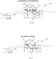
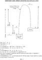
- Figure 1A shows an example of a saltwater to freshwater component of a hydraulic desalination system, configured according to the principles of the disclosure, generally denoted by reference numeral 100, and also shows a simplified process of the overall progression of seawater to freshwater, according to principles of the invention.
- Figure 1B shows an example of a saltwater to brine water component of the hydraulic desalination system, configured according to the principles of the disclosure, generally denoted by reference numeral 101, and also shows a simplified process of the overall progression of seawater to brine, according to principles of the invention.
- a generalized exemplary hydraulic desalination device and method include lowering the pressure of liquid saltwater to the vaporization point by generating flow through piping and accompanying infrastructure, capturing the vapor, condensing the vapor using higher pressure supplied by the ambient surroundings producing freshwater, recovering the heat released during condensation by maintaining ambient temperatures greater than vapor temperatures, and then using the recovered heat to enhance and perpetuate vaporization in a cyclical manner.
- Figures 1A and 1B show an example of a pump station that houses a water vaporization tank 120 that comprises a containment vessel, a pump system 125 for pumping water, including saltwater and freshwater through the desalination system 100, and a plurality of funnels separated by a partition 130.
- the Figures 1A and 1B show an example of the pump station infrastructure in relation to ground elevation and a saltwater source.
- An air nozzle 174 is also shown configured to inject air into the freshwater side.
- Figure 1A illustrates more clearly the saltwater to freshwater aspects
- Figure 1B illustrates more clearly the saltwater to brine aspects.
- Fig. 1A also shows a simplified process of the overall progression of seawater to freshwater
- Fig. 1B also shows a simplified process of the overall progression of seawater to brine, according to principles of the invention.
- step S1 illustrates a force main for conveying a flow of seawater from a source such as an ocean, or the like, to a desalination system 100.
- seawater may encounter force main friction valves.
- the seawater flows into a funnel 135b ( Fig. 2A ).
- the seawater may be contained by a partition 130 in a water vaporization tank 120 to create an upstream containment section.
- the seawater may vaporize, as described in more detail below, to create a vapor portion within the vaporization tank 120.
- the vapor portion may condense within the water vaporization tank 120 and may be captured as liquid freshwater creating a downstream containment section.
- the downstream containment section may be contained by a funnel 135b in conjunction with partition 130.
- the freshwater may traverse suction piping with friction valves, e.g., set friction valves.
- the freshwater may include about 2% injected air.
- the freshwater may enter pumps (e.g., 165a-165e of Figs. 3A and 3B ), and may be discharged to a freshwater storage area.
- steps S1 to S4 are the same as described previously in reference to Fig. 1A .
- brine that collects in the upstream containment section of funnel 135a flows to a first part of suction piping (see, e.g., Fig. 3B ).
- the brine continues progression through a second part of the suction piping.
- the brine moves through a third part of the suction piping.
- the brine encounters the pumps (e.g., 165a-165e of Figs. 3A and 3B ) and may be discharged to a brine containment area.
- Each of the pumps (e.g., 165a-165e of Figs. 3A and 3B ) may be configured to pump both freshwater and saltwater simultaneously, as described in more detail below.
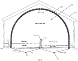
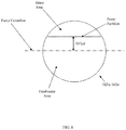
- a pump station 115 is configured to include a water vaporization tank 120 shown as an enclosing curved structure to encompass a vapor space 122, a plurality of funnels 135a and 135b separated by a partition 130, and one or more heat conduits 140 coupled to a heat source 145 and to vaporization tank 120 to permit heating of the interior of the vaporization tank 120.
- the partition 130 may be configured to separate the saltwater (shown on the left) from the freshwater (shown on the right) that is produced and captured by the desalination process described herein.
- a tank cap 160 permits access to the vaporization tank such as, for example, for use in evacuation of the vaporization tank 120, or cleaning of the vaporization tank 120.
- Funnel 135a comprises a saltwater retaining structure and is configured with a force main pipe connector 150 for connecting the force main pipe 1 ( Figure 3B ), and also configured to couple to and receive suction pipe 12 ( Figure 3B ).
- Funnel 135b comprises a freshwater retaining structure and may be configured with a suction pipe connector 155 that may connect to suction pipe 5 ( Figures 3A and 3B ).
- the vaporization tank 120 may comprise a containment vessel that may be configured to substantially enclose an upstream containment section and a downstream containment section, and may contain water vapor for condensation, as explained more fully below.
- the tank partition 130 may also be configured to house a heat exchanger 131 which may provide a thermal flow path from the freshwater downstream side to the seawater upstream side for heat released during condensation.
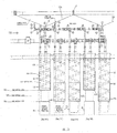
- Figure 3A shows a sequential, top-down view of an example of a plurality of hydraulic desalination pump devices of a pump system, configured according to the principles of the disclosure.
- Figure 3B shows a side cross-sectional view of the plurality of hydraulic desalination pump devices of Figure 3A , as well as an exemplary sequence of operation thereof, and exemplary valves and piping for connecting to the funnels 135a, 135b of Figures 2A and 2B .
- Table 1 provides a cross-reference of examples of certain various components that may be included with the plurality of hydraulic desalination pump devices of Figures 3A and 3B , showing reference numbers (1-28), exemplary quantity (which may vary depending on specific application), and illustrative description of the components.
- TABLE 1 Pipe Schedule for Constant Flow - 1,200 GPM Station Ref. # Quant.
- the hydraulic desalination pump devices 165a-165e may function as the prime movers of water for the hydraulic desalination system and process described herein.
- the hydraulic desalination system and process may involve use of hydraulic desalination pump devices 165a-165e, which may be spring-loaded pumps, in combination with valves and piping 170 (parts of the infrastructure), as shown in Figure 3B , and an air nozzle, vaporization tank and other equipment as shown in Figures 1A and 1B .
- These elements combine to create a thermodynamic siphon, an example of which is shown in Figure 5 , which effectively bypasses the normally prohibitive heat of vaporization step associated with traditional desalination processes, thereby greatly reducing overall energy requirements.
- Each of hydraulic desalination pump devices 165a-165e has a simple configuration that is generally free of the intricate internal components, small tubing, and narrow passageways that cause the large friction losses within traditional pumps.
- the configuration may include a relatively large, cylindrical pump cavity 164 that may be expanded by a compression spring 163 of similar diameter and/or similar circumference.
- each of the of hydraulic desalination pump devices 165a-165e may be configured with two pipe inlets (5 and 19) and two pipe outlets (11 and 24). All four pipe inlets and outlets may be positioned atop the respective hydraulic desalination pump devices 165a-165e.
- a single inlet (5) and outlet (11) pairing may be used for suction and discharge of a mixture of freshwater and air.
- Another inlet (19) and outlet (24) pairing may be used for suction and discharge of brine.
- the mixed flow of freshwater and air is kept separate from the brine flow by a partition within the pump cavity 164 (and spring).
- the pump partition for example, as illustrated in Figure 8 , may be positioned such that approximately 90% of flow drawn by the respective hydraulic desalination pump devices 165a-165e includes the mixed flow of freshwater and air, while the remaining approximate 10% includes brine. This ratio may maximize the efficiency of desalinating typical seawater or other saltwater source while still maintaining salt in solution in the brine. Other ratios and partition positions can be selected, if necessary, to accommodate different saltwater salinities or smaller desalination units.
- Figure 3B also illustrates the sequence of operation of the of hydraulic desalination pump devices 165a-165e, according to the principles of the invention.
- the spring 163 causes the pump cavity 164 to expand downwards at a relatively slow rate.
- an electromechanical press 166 or other similar powered press mechanism at the bottom of the pump may be activated to begin compressing the cavity to its original non-expanded position.
- brine and freshwater/air are discharged through their outlets (11 and 24) and sent to respective storage areas.
- Each of the four operating hydraulic desalination pump devices 165a-165d may operationally rotate rhythmically, but asynchronously, through the steps shown below in TABLE 2 which also shows the operation of flow valves in relation to the operation of the hydraulic desalination pump devices 165a-165d.
- Pump position 1 corresponds to 160a
- pump position 2 corresponds to 160b
- pump position 3 corresponds to 160c as shown in Figure 3B .
- Step 1 (& sub-steps) Step 2 (& sub-steps) Step 3 (& sub-steps) Step 4 (& sub-steps) 1-1.
- 2-1 Flow valves on suction piping in fully-open position.
- steps P2, P3 and P4 may be treated as a single step since the transition from step P1 to step P2 for a small unit configuration may take a relatively long time to occur.
- Continuous flow is typically needed in order to prolong the desalination process; otherwise, vaporization may cease while a hydraulic desalination pump device is discharging water.
- a plurality (e.g. two, three, four or five) of the hydraulic desalination pump devices may be installed in parallel, with flow valves (e.g., flow valve 22) attached to each pump's suction and/or discharge lines.
- the hydraulic desalination pump devices 165a-165d may operate rhythmically such that only one hydraulic pump at a time draws flow.
- One of the hydraulic desalination pump devices may serve as a redundant spare pump 165e. In the event of a failure to one of the other operating pump devices, the spare pump device 165e can be started and continuous flow maintained.
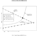
- All of the hydraulic desalination pump devices 165a-165e have a specific characteristic or relationship with regards to their ability to deliver flow rates and exert pressure (or head). But, in general, a pump exerts more pressure to the surroundings when it is pumping fluid at a low flow rate. Conversely, a pump exerts less pressure to the surroundings when it is pumping fluid at a high flow rate. This relationship exists within the pump device itself, regardless of how the flow rate affects the surroundings, and is known as a pump curve. A typical pump curve is shown in Figure 6 .
- a traditional pump has internal mechanisms, tubing, passageways, etc. that are so affected by flow rate within the pump that the pump's ability to exert pressure on its surroundings diminishes as the flow rate increases. This diminished capacity is due to friction losses within the pump as the flow rate and, more importantly, flow velocities increase within the pump. Friction losses are heavily dependent upon flow velocities, and a small increase in flow velocity can result in a comparatively much larger increase in friction loss.
- NPSHR Net Positive Suction Head Required
- NPSHA Net Positive Suction Head Available
- Hydraulic desalination takes advantage of a pump's ability to cause vaporization when friction losses equal or exceed NPSHA.
- vaporization within any pump may be problematic, particularly for traditional pumps. Vaporization (cavitation) may also occur within the suction piping external to the pump if friction losses within the piping match or exceed the NPSHA.
- vaporization in piping is not recommended either, as expansion and bursting of vapor bubbles within the limited confines of pipes cause damage to pipe walls similar to the damage caused to the internal components of pumps.
- a hydraulic desalination process and system include, but are not limited to, the following equipment and features:
- the hydraulic desalination pump devices e.g., 165a-165e configured according to the principles of the invention are designed specifically for hydraulic desalination on scales ranging from small (e.g. less than 10 gallons per minute or gpm) to large (e.g. greater than 1,000 gpm).
- the hydraulic desalination pump devices 165a-165e are configured substantially free of the intricate internal components, small tubing, and narrow passageways that cause the large friction losses within traditional pumps. As previously described, this configuration generally includes a relatively large, cylindrical pump cavity 164 that may be expanded by a compression spring 163 of similar diameter. Each of the hydraulic desalination pump devices 165a-165e may have two inlets and two outlets, with all four pipes positioned atop of the hydraulic desalination pump device 165a-165e. As previously described in relation to Figure 3A , one inlet and outlet pairing may be used for suction and discharge of a mixture of freshwater and air. The other inlet and outlet pairing may be used for suction and discharge of brine.
- the mixed flow of freshwater and air is kept separate from the brine flow by a partition within the pump cavity (and spring), as shown, e.g., in Figure 8 .
- the partition within the pump cavity, as shown in Figure 8 may be positioned such that approximately 90% of flow drawn by the pump includes the mixed flow of freshwater and air, while the remaining 10% includes brine. That ratio maximizes the efficiency of desalinating typical seawater while still maintaining salt in solution in the brine. Other ratios and partition positions can be selected, if necessary, to accommodate different saltwater salinities or smaller desalination units at the expense of efficiency.
- the spring 163 may cause the pump cavity 164 to expand downwards at a relatively slow rate.
- an electrical/mechanical press at the bottom of each of the hydraulic desalination pump devices 165a-165e may be activated and may begin compressing the cavity to its original position. During compression, brine and freshwater/air are discharged through their outlets and sent to respective storage areas.
- a plurality e.g., 2-5, or more
- spring-loaded hydraulic desalination pump devices 165a-165e may be installed in parallel, with flow valves attached to each pump device's suction and discharge lines.
- the hydraulic desalination pump devices 165a-165e operate rhythmically such that only one hydraulic desalination pump device 165a-165e at a time draws flow.
- One of the pumps e.g., 165e
- the spare pump may be started and continuous flow can be maintained.
- a residual benefit of the hydraulic desalination pump device's 165a-165e simple design is that mixtures of air and water should not adversely affect the pump's ability to function.
- Traditional pumps that are intended to pump either liquids or gases often deal poorly with the differing velocities and densities associated with liquid-gas mixtures. Flow velocities within spring-loaded pumps should be too low to cause any serious problems, despite the differing densities.
- Dimensions and sizing for the compression spring may be governed by some general guidelines for springs, as well as the time it takes for the flow valves associated with the pumps to open and close. These guidelines may include:
- F the force required to cause expansion of the spring
- k is a constant based largely on the spring's material properties
- x is the length of expansion.
- spring-loaded pumps i.e., the hydraulic desalination pump device 165a-165e
- spring-loaded pumps have pump curves and NPSHR curves that are independent of the flowrate through the pump. Because spring-loaded pumps have no intricate internal components, small tubing, or narrow passageways that cause the large friction losses, their pump curves and NPSHR curves are completely horizontal, as shown in relation to Figure 7 .
- the only factor that affects the pump's ability to exert head (or pressure) to the surroundings is the position of the spring's leading face during expansion. Once the fluid reaches the pump in liquid form, nothing within the pump can cause that liquid to cavitate.
- the NPSHR curve for spring-loaded pumps is not only completely horizontal, but it is equal to zero for virtually all flows.
- Figure 7 shows an example pump curve and NPSHR curve for spring-loaded pumps, such as the hydraulic desalination pump device 165a-165e.
- the major benefit of having no NPSHR is that the pump is very safe and efficient to use in the low NPSHA environment of hydraulic desalination.
- FIG. 4 shows a sequential, top-down view of an example of the friction valves and flow valves associated with the hydraulic desalination pump devices, configured according to the principles of the disclosure, and also shows an illustrative sequence of operation thereof.
- Flow valves e.g., flow valve 22, 70
- Flow valves can include, e.g., stop valves, stop-check valves, non-return check valves, pinch valves, or any other similarly functioning valve.
- Flow valves may be hydraulically or electrically actuated to operate in accordance with the pump sequence of operations (and adjusting friction valve sequence of operations).
- Friction valves include valves that are configured to restrict flow in piping upstream from the vaporization tank 120. The goal of using friction valves is to impart friction head on the saltwater flow such that vaporization occurs where desired in the vaporization tank 120.
- Friction valves 25, 75 may be either set or adjusting. Set friction valves are set to one partially-closed position that doesn't change during hydraulic desalination. Adjusting friction valves may be adjusted from partially-closed to more-fully closed positions during hydraulic desalination.
- Flow valves 22, 70 may be used in conjunction with adjusting friction valves to give the adjusting friction valves time to reset from the more-fully closed position to the partially-closed position.
- adjusting friction valves may operate rhythmically and in parallel to maintain continuous flow.
- the inclusion of at least one spare adjusting friction valve is suggested for redundancy in the event of failure by one or more of the other operating adjusting friction valves.
- a valve such as, e.g., a cycle stop valve (CSV) has the performance characteristics necessary to operate as either a set or adjusting friction valve in hydraulic desalination. Adjusting friction valve sequence of operations is explained in relation to Figure 4 , as described next.
- CSV cycle stop valve
- the operation of friction valves includes the rhythmical, but asynchronous rotation, through the following steps of TABLE 3.
- F-1 Adjusting friction valve in partially-closed position.
- F-1 Adjusting friction valve in more-fully closed position.
- F-1 Adjusting friction valve in partially-closed position.
- F-2 Downstream flow valve on force main in fully-open position.
- F-2. Downstream flow valve on force main in fully-open position.
- F-2 Downstream flow valve on force main in fully-open position.
- F-3 Adjusting friction valve undergoing this step does so synchronously with pump undergoing Step 1 of pump sequence of operations. (TABLE 2).
- F-3 Adjusting friction valve undergoing this step does so synchronously with pump undergoing Step 1 of pump sequence of operations.
- Adjusting friction valve undergoing this step does so synchronously with pump undergoing step 2 of pump sequence of operations (TABLE 2).
- F-3. Adjusting friction valve undergoing this step does so synchronously with pumps undergoing steps 3 and 4 of pump sequence of operations (TABLE 2).
- F-4. Flow through adjusting friction valve equals maximum flow (Step 1 of pump sequence of operations TABLE 2).
- F-4. Flow through adjusting friction valve equals minimum flow (Step 2 of pump sequence of operations TABLE 2).
- F-4. Flow through adjusting friction valve equals zero (steps 3 and 4 of pump sequence of operations of TABLE 2).
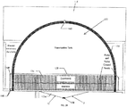
- the vaporization tank 120 is where vaporization can occur safely during the process of hydraulic desalination.
- the vaporization tank 120 may be sized to limit vapor flow velocities to below, e.g., about 200 feet-per-second (fps), which is generally accepted as the flow velocity limit for steam.
- the vaporization tank 120 may have a partition wall 130 through its centerline to separate the seawater on the upstream side from the freshwater on the downstream side.
- the tank partition 130 may also be configured to house the heat exchanger 131 which may provide the flow path from the freshwater side to the seawater side for heat released during condensation.
- the vaporization tank 120 is typically the largest single piece of equipment in the hydraulic desalination process.
- a certain level of non-condensable gases like oxygen and nitrogen may collect in the vaporization tank during hydraulic desalination. This level should remain constant and should not interfere significantly with the performance or efficiency of the desalination process. However, if the non-condensable gases in the vaporization tank do accumulate to an unacceptable level, vacuum pumps may be installed in the tank to discharge the excess non-condensable gases.
- Two funnels 135a, 135b may be used in hydraulic desalination.
- One funnel 135a may be configured on the upstream side of the vaporization tank 120, and the other funnel 135b may be configured on the downstream side. Both funnels provide transitions between piping (where, by industry standard, liquid water flows at velocities ranging from, e.g., about 2 to about 8 fps) and the vaporization tank 120 (where water vapor flows at velocities up to, e.g., about 200 fps).
- the upstream funnel also provides openings at its floor from which brine flow is drawn into brine suction piping that ultimately terminates at the hydraulic desalination pump device 165a-165e.
- the mixture of freshwater and air at the downstream funnel 135b have a salinity of approximately 0%.
- the air nozzle is a small but an important part of hydraulic desalination.
- the air nozzle introduces air into the freshwater flow immediately after the downstream funnel.
- the important aspect of this step is that the air, although ambient, has a higher pressure and temperature than the water vapor in the vaporization tank.
- Ambient air pressure and temperature may be, e.g., about 14.7 psi and 72 degrees Fahrenheit, respectively.
- the pressure of the water vapor may be, e.g., approximately 0.3 psi, and its temperature may be, e.g., approximately 68 degrees Fahrenheit. It is noted that vaporization may be created strictly by lowering pressure through friction losses. No heat was added that would raise the temperature of the seawater/saltwater, which is generally considered to be approximately 68 degrees Fahrenheit, but may vary.
- Hydraulic Desalination involves a technique to lower the pressure of liquid saltwater to the vaporization point by generating flow through piping and appurtenances, capturing the vapor, condensing the vapor using higher pressure supplied by the ambient surroundings and recovering the heat released during condensation by maintaining ambient temperatures greater than vapor temperatures. Recovered heat may be used to enhance and perpetuate vaporization in a cyclical manner.
- Hydraulic Desalination may transform saltwater into two end products: freshwater and brine.
- the steps provided below illustrate an exemplary chronological path of saltwater as it undergoes Hydraulic Desalination from start to finish and is transformed into the two end products.
- the steps may include:
- the steps may include:
- Hydraulic desalination according to the principles of the present disclosure is not subject to some of the other problems that plague traditional desalination processes. For instance, currently utilized thermal processes of present day desalination processes that rely on high temperatures often have problems with scaling, where salt comes out of solution and attaches to, clogs, or corrodes piping and equipment. Membrane-based technologies are also susceptible to scaling due to the very fine openings in the semi-permeable membranes. Even a small amount of scaling on these membranes will have a large negative impact on their performance. Pre-treatment is usually necessary for membrane-based technology to address issues with scaling and remove debris that can foul the membranes.
- Hydraulic desalination is not as prone to problems from scaling, as it does not operate at higher temperatures which promote scaling, and it does not have equipment that is highly sensitive to small amounts of scaling. Furthermore, unlike membrane-based processes, hydraulic desalination does not require special pre-treatment.
- a typical siphon water flow is raised from an upstream tank or source over a vertical barrier, then back down to a downstream tank or sink that is lower than the upstream source.
- the water flow in a typical siphon is sustained naturally and indefinitely without adding any external energy.
- the only real work that needs to be done for the siphon is in the preparation.
- the tube through which water flows first needs to be filled with water. This can be done away from the source and sink. Once filled, both ends of the tube are capped. One end of the tube is then placed in the upstream source and the other end is placed in the downstream sink. The tube's ends are then uncapped and, assuming virtually constant levels at the source and sink, flow proceeds naturally and indefinitely with no further energy required to sustain it, effectively bypassing the intermediate vertical barrier.
- hydraulic desalination involves a type of siphon, a sort of thermodynamic siphon that simulates the typical siphon in many ways.
- thermodynamic siphon energy is raised over the heat of vaporization, then back down to a much lower energy.
- the desalination process is sustained with just the energy supplied by the relatively low-powered, hydraulic desalination pump devices 165a-165e.
- the real work that needs to be done is in the preparation.
- the downstream air nozzle is shut off and the vaporization tank is filled with water. Then the tank 120 is isolated by shutting off the upstream gate valve.
- the heaters and hydraulic desalination pump device 165a-165e are then turned on to begin evacuation of the tank. Once the water level has been lowered to the desired elevation, the gate valve and the air nozzle are both opened. The heaters are then turned off, but the spring-loaded pumps are kept in operation. Hydraulic desalination proceeds naturally and indefinitely with no additional external heat or energy required to sustain the process.
- the spring-loaded pumps When priming the thermodynamic siphon, the spring-loaded pumps may prove to be incapable of filling the vaporization tank. Pumps can't pull a liquid. Instead, the spring-loaded pumps use friction to lower the pressure on one side of flow, allowing atmospheric pressure to push the flow from the other side. If the vaporization tank is sufficiently tall, the atmospheric pressure will not be strong enough to push flow to the top of the tank. If this happens, submersible pumps can be placed in the seawater source, or a fire hydrant can be used, to push water to the top of the tank.
- the air nozzle is important to the success of hydraulic desalination.
- the air nozzle 174 is the thermodynamic siphon that drives hydraulic desalination.
- the air introduced at the air nozzle 174 forces condensation, and it also forces heat flow towards where vaporization is occurring.
- the air forces these events because, although ambient, it has a higher pressure and temperature than the water vapor.
- the water vapor has no alternative but to condense and release heat towards the path of least resistance, which is the heat flow path through the heat exchanger 131 to the upstream side of the tank 120 where vaporization is taking place.
- the heat released during condensation called the heat of condensation
- Recycling heat in this manner means the barrier, heat of vaporization, is effectively bypassed during hydraulic desalination.
- the heaters 145 should only be needed during initial evacuation. However, if necessary, the heaters 145 could be used to heat the ambient surroundings to ensure that the ambient air maintains a higher temperature than the water vapor 122 in the tank. Otherwise, low ambient air temperatures may result in heat loss to the ambient surroundings during condensation and reduced efficiency of the hydraulic desalination process.
- the energy grade line is what is used to calculate the energy associated with fluid flow. The purpose of these calculations is to determine the operating point for the hydraulic desalination pump devices.
- the operating point is the point where the pump curve intersects with the system curve.
- the system curve also called Total Dynamic Head (TDH) curve, is the resistance to flow that exists in the piping/equipment external to the hydraulic desalination pump devices.
- the operating point is normally described as a specific flowrate at a specific pressure or head.
- An example of operating points and system curves is shown in Figure 6 .
- the minimum energy required to remove salt dissolved in water is generally accepted to be, e.g., approximately 0.7 kilowatt-hours per cubic meter (kWh/m3). This minimum energy is determined either from heat (enthalpy) of solution data for dissolved salt, or from the difference in equilibrium vapor pressures between seawater and freshwater.
- the heat of solution method for calculating the minimum energy applies to membrane-based technologies.
- the differing equilibrium vapor pressures method relates to the thermal desalination technologies. Hydraulic desalination is a form of thermal desalination, but unlike other forms of thermal desalination, it does not require a man-made compressor to condense seawater equilibrium vapor pressure to match freshwater equilibrium vapor pressure.
- That compression is done automatically by the higher-pressure atmospheric air introduced into the system.
- the air not only transforms the vapor into liquid water, but it also causes the necessary preliminary vapor compression.
- the vapor compression is done by the introduced ambient air, the corresponding, e.g., about 0.7 kWh/m 3 of energy does not need to be supplied.
- the only energy that needs to be supplied is for the pumps and valves, which is much less than 0.7 kWh/m 3 . Therefore, the minimum energy requirement that is generally accepted for desalination does not apply to hydraulic desalination in the same way that it applies to other processes. Much like the way hydraulic desalination recycles the heat necessary for vaporization, the minimum energy required for separation is obtained from within the process itself.
- the footprint may be approximately 56 feet by 58 feet, and the overall vertical span may be approximately 67 feet. Of that vertical span, about 38 feet may be above ground (including an A-frame roof), and roughly 29 feet may be below ground.
- the above ground structure may be a 1-story building with a 21-foot high ceiling, approximately.
- the vaporization tank 120, heaters 145 (for initial evacuation), and any control panels may reside in the above ground portion of the building 115.
- Staircases and hatches may be installed to provide access to the piping and pumps below ground.
- the building 115 may include two levels below ground.
- the first level below ground may house the majority of the piping.
- the second level below ground may be where the pumps are located.
- Five pumps might be installed. Four pumps may operate together to maintain continuous flow, while the last pump may be available as a spare.
- Springs in the hydraulic desalination pump device may be 54 inches in diameter with a spring constant k (a measure of a spring's potential to expand) of 977 pounds per foot (lbs/ft), approximately.
- the hydraulic desalination pump devices may draw flow at a constant rate of, e.g., about 1,200 gpm.
- the station 115 may be equipped with a gate valve 160 (for initial evacuation) and a set friction valve, both upstream from the vaporization tank 120. Although the station may have only one set friction valve, the seawater level in the vaporization tank will remain essentially constant along the 8-foot height of the tank partition as the pumps operate, due to the constant flow generated by the pumps.
- the power-to-water ratio for this station may be determined to be, e.g., about 0.02 megawatts per million imperial gallons (MIGD), or about 0.005 megawatts per thousand cubic meters per day (MW/1,000 cubic meters per day).
- This example includes a packaged unit that may be assembled before or after delivery to the site.
- the packaged unit includes outer walls that may include removable panels to allow access to the interior by personnel.
- the footprint may be approximately 11 feet by 14 feet, and the overall vertical span may be approximately 22 feet.
- All of the vertical span may be above ground or atop a building floor/ship deck, and it may include, e.g., three levels.
- the vaporization tank and heaters (for initial evacuation) may reside in the top level.
- Most of the piping may be installed in the second level.
- the hydraulic desalination pump devices may be located in the bottom level, and the control switches may be located in the top level or second level to permit the controls to be at the eye level of most personnel.
- Three pumps may be installed. Two pumps may operate together to maintain continuous flow, while the last pump may be available as a spare.
- Springs in the pumps may be, e.g., about 42 inches in diameter with a spring constant k of, e.g., about 601 lbs/ft, approximately.
- the hydraulic desalination pump devices may draw flow at a constant rate of, e.g., about 8 gpm.
- the unit may be equipped with a gate valve (for initial evacuation) and one set friction valve, both upstream from the vaporization tank 120. Although the unit may only have one set friction valve, the seawater level in the vaporization tank will remain essentially constant along the 2-foot height of the tank partition as the pumps operate, due to the constant flow generated by the pumps.
- the power-to-water ratio for this unit may be estimated to be, e.g., about 0.02 megawatts per million imperial gallons (MIGD), or about 0.005 megawatts per thousand cubic meters per day (MW/1,000 cubic meters per day).
- This example includes a built-on-site pump station.
- the footprint may be approximately 56 feet by 58 feet, and the overall vertical span may be approximately 63 feet. Of that vertical span, about 38 feet may be above ground (including an A-frame roof), and roughly 25 feet would be below ground.
- the above ground structure may be a 1-story building with a 21-foot high ceiling, approximately.
- the vaporization tank 120, heaters 145 (for initial evacuation), and control panels may reside in the above ground portion of the building. Staircases and hatches may be installed to provide access to the piping and pumps below ground.
- the building may include two levels below ground.
- the first level below ground may house the majority of the piping.
- the second level below ground may be where the pumps are located.
- Five pumps may be installed. Four pumps may operate together to maintain continuous flow, while the last pump may be available as a spare.
- Springs in the pumps may be, e.g., about 54 inches in diameter with a spring constant k of, e.g., about 3,520 lbs/ft, approximately.
- the pumps may draw flow at rates ranging from, e.g., about 994 to about 1,394 gpm, averaging, e.g., about 1,200 gpm overall.
- the station may be equipped with a gate valve (for initial evacuation) and four adjusting friction valves, all upstream from the vaporization tank. Because the station has several adjusting friction valves operating in sequence, the seawater level in the vaporization tank may remain virtually unchanged along the 8-foot height of the tank partition as the pumps operate.
- About 90% of the total flow coming into the station may be converted to freshwater, which means the station may produce freshwater at a rate of, e.g., about 1,080 gpm, approximately.
- Total power required by the station is conservatively estimated to be, e.g., about 40 horsepower, or 30 kilowatts, to account for all power consumption. In actuality, it may require less power.
- the majority of the power may serve to drive or power the electrical/mechanical presses that compress the pump cavities and discharge flow. Remaining power consumption may be divided amongst the valves, control panel, lighting, and, if necessary, heating of ambient surroundings.
- the power-to-water ratio for this station may be determined to be, e.g., about 0.02 megawatts per million imperial gallons (MIGD), or about 0.005 megawatts per thousand cubic meters per day (MW/1,000 cubic meters per day).
- This example includes a packaged unit that could be assembled before or after delivery to the site.
- the packaged unit includes outer walls that may include removable panels to allow access to the interior by personnel.
- the footprint may be, e.g., approximately 7 feet by 7 feet, and the overall vertical span may be approximately 13 feet.
- All of the vertical span may be above ground or atop a building floor/ship deck, and it would include three levels.
- the vaporization tank 120 and heaters 145 (for initial evacuation) may reside in the top level.
- Most of the piping may be installed in the second level.
- the control switches may also be located on the top or on the second level to permit the controls to be at the eye level of most personnel.
- the pumps may be located in the bottom level. Five pumps may be installed. Four pumps may operate together to maintain continuous flow, while the last pump may be available as a spare.
- Springs in the pumps may be, e.g., about 10 inches in diameter with a spring constant k of, e.g., about 211 lbs/ft.
- the pumps may draw flow at rates ranging from, e.g., about 6.93 to about 9.03 gpm, averaging, e.g., about 8 gpm overall.
- the unit may be equipped with a gate valve (for initial evacuation) and four adjusting friction valves, all upstream from the vaporization tank 120. Because the unit has several adjusting friction valves operating in sequence, the seawater level in the vaporization tank may remain virtually unchanged along the 2-foot height of the tank partition as the pumps operate.
- the power-to-water ratio for this unit may be determined to be, e.g., about 0.02 megawatts per million imperial gallons (MIGD), or about 0.005 megawatts per thousand cubic meters per day (MW/1,000 cubic meters per day).
- Each of the above examples may have certain relative advantages and may have certain relative disadvantages. For the most part, the advantages and disadvantages may come down to size and complexity.
- the constant flow examples are larger than the varying flow examples; however, their size may be offset by their simpler design and operation.
- the constant flow examples may have only one set friction valve upstream from the vaporization tank instead of the four adjusting friction valves operating in sequence in the varying flows examples.
- the difference in size is approximately 4 feet in vertical span.
- the constant flow, 1,200 gpm example has 67 feet in vertical span including 29 feet below ground, while the varying flows version has 63 feet of vertical span including 25 feet below ground, making the constant flow example about 16% deeper below ground than its varying flows counterpart.
- the difference in size is quite significant in footprint and vertical span.
- the constant flow, 8 gpm example has a footprint of 11 feet by 14 feet, and a vertical span of 22 feet.
- the varying flows, 8 gpm example has a footprint of 7 feet by 7 feet, and a vertical span of 13 feet. This makes the constant flow example about 3 times as large in footprint (154 square feet vs. 49 square feet) and roughly 69% taller. This difference in size is more likely to be viewed as a compelling reason to use a variable flow configuration, even with the simpler design and operation of the constant flow counterpart.
- spring-loaded pumps Although other types of pumps currently in existence could theoretically be used in hydraulic desalination, the new spring-loaded pumps described herein have several distinct advantages. Some of the unique benefits that spring-loaded pumps provide may include the following:
- Hydraulic desalination is an exciting, new process for desalinating water that appears to be at least 20 times more efficient than other desalination processes, and is viable for virtually all desired water production flowrates. It has been demonstrated to be feasible for small applications (less than 10 gpm) and large applications (more than 1,000 gpm) examples alike, with all applications benefitting from the thermodynamic siphon effect that drives hydraulic desalination. Unlike other processes, hydraulic desalination is not prone to scaling on its equipment, and special pre-treatment is not necessary to avoid scaling. Some equipment (e.g., valves, air nozzle) necessary for the operation of this new process is already in existence and use in other non-desalination industries. Other equipment (e.g., vaporization tank, funnels, heat exchanger) may be specifically constructed for hydraulic desalination, and the spring-loaded hydraulic desalination pump device 165a-165e may be a new product/device in its entirety.
- Some equipment e.g., valves, air nozzle
Landscapes
- Chemical & Material Sciences (AREA)
- Chemical Kinetics & Catalysis (AREA)
- Engineering & Computer Science (AREA)
- Organic Chemistry (AREA)
- Hydrology & Water Resources (AREA)
- Life Sciences & Earth Sciences (AREA)
- Environmental & Geological Engineering (AREA)
- Water Supply & Treatment (AREA)
- General Engineering & Computer Science (AREA)
- Mechanical Engineering (AREA)
- Inorganic Chemistry (AREA)
- Heat Treatment Of Water, Waste Water Or Sewage (AREA)
- Vaporization, Distillation, Condensation, Sublimation, And Cold Traps (AREA)
- Separation Using Semi-Permeable Membranes (AREA)
Applications Claiming Priority (4)
| Application Number | Priority Date | Filing Date | Title |
|---|---|---|---|
| US201161486596P | 2011-05-16 | 2011-05-16 | |
| US201261608428P | 2012-03-08 | 2012-03-08 | |
| US201261613728P | 2012-03-21 | 2012-03-21 | |
| PCT/US2012/031250 WO2012158264A2 (en) | 2011-05-16 | 2012-03-29 | Hydraulic desalination device and method |
Publications (3)
| Publication Number | Publication Date |
|---|---|
| EP2709957A2 EP2709957A2 (en) | 2014-03-26 |
| EP2709957A4 EP2709957A4 (en) | 2015-12-30 |
| EP2709957B1 true EP2709957B1 (en) | 2018-02-21 |
Family
ID=47175053
Family Applications (1)
| Application Number | Title | Priority Date | Filing Date |
|---|---|---|---|
| EP12785549.2A Active EP2709957B1 (en) | 2011-05-16 | 2012-03-29 | Desalination method |
Country Status (13)
Families Citing this family (4)
| Publication number | Priority date | Publication date | Assignee | Title |
|---|---|---|---|---|
| CN103842298B (zh) | 2011-05-16 | 2015-10-21 | 马文·皮埃尔 | 液压脱盐装置和方法 |
| WO2015013481A1 (en) * | 2013-07-25 | 2015-01-29 | Pierre Marvin | Desalination using atmospheric pressure as renewable energy |
| CN110200218A (zh) * | 2019-05-16 | 2019-09-06 | 四川望红食品有限公司 | 一种袋装低盐豆瓣及其生产加工方法 |
| CN117208998B (zh) * | 2023-11-09 | 2024-03-19 | 福建浩达智能科技股份有限公司 | 一种用于对海水进行淡化的装置、方法以及设备 |
Family Cites Families (34)
| Publication number | Priority date | Publication date | Assignee | Title |
|---|---|---|---|---|
| US1309943A (en) * | 1919-07-15 | Apparatus for pumping fluid | ||
| US2236035A (en) * | 1937-12-04 | 1941-03-25 | Bailey Meter Co | Fractionating tower control |
| US3102083A (en) * | 1960-04-20 | 1963-08-27 | Nash Engineering Co | Pumping means for distillation unit |
| US3364126A (en) * | 1964-05-28 | 1968-01-16 | Gen Kinetics Inc | Latent heat distillation and condensation systems |
| US3304006A (en) * | 1965-08-13 | 1967-02-14 | Nash Engineering Co | System for handling fluids in both liquid and gaseous phases |
| US3440146A (en) * | 1966-05-02 | 1969-04-22 | Johan A Louw | Desalination method and apparatus with plural vaporization chambers containing shallow layers of liquid |
| US3783108A (en) * | 1971-01-18 | 1974-01-01 | R Saari | Method and apparatus for distilling freshwater from seawater |
| US3859069A (en) | 1971-06-17 | 1975-01-07 | Pacific Lighting Service Co | Vacuum freezing vapor compression apparatus |
| US4035241A (en) * | 1976-02-09 | 1977-07-12 | Carman Vincent Earl | Method and apparatus for purifying a liquid by pressure distillation |
| DE3037293A1 (de) * | 1980-10-02 | 1982-05-27 | Helmut 7100 Heilbronn Bälz | Ferndampfsystem mit gemeinsamer kondensatrueckfuehrung und verfahren zur kondensatrueckfuehrung |
| EP0309596B1 (en) * | 1987-09-26 | 1993-03-31 | Hewlett-Packard GmbH | Pumping apparatus for delivering liquid at high pressure |
| US5744008A (en) * | 1996-01-02 | 1998-04-28 | Oceanit Laboratories, Inc. | Hurricane tower water desalination device |
| KR970069882A (ko) * | 1996-04-17 | 1997-11-07 | 원승호 | 담수화설비의 정수장치 및 그 방법 |
| FR2809385A1 (fr) * | 2000-05-26 | 2001-11-30 | Tsb Internat | Methode et installation d'epuration et de dessalement de l'eau de mer |
| FR2814738A1 (fr) * | 2000-09-29 | 2002-04-05 | Ahmed Bentoutouh | Procede de distillation d'eau et d'autres liquides sous vide dans une installation mono et multi-colonne |
| CA2466849A1 (en) * | 2001-10-03 | 2003-04-10 | Yaron Mayer | System and method for efficient and low energy desalination of water |
| US20040055866A1 (en) * | 2002-09-20 | 2004-03-25 | Levine Michael R. | Desalinization still |
| CA2446829A1 (en) * | 2002-10-25 | 2004-04-25 | Yaron Mayer | System and method for efficient and low energy desalination of water |
| RU2234354C1 (ru) * | 2003-09-10 | 2004-08-20 | Общество с ограниченной ответственностью "Научно-производственная фирма "ТГМ" | Опреснитель |
| RU2234355C1 (ru) * | 2003-09-10 | 2004-08-20 | Общество с ограниченной ответственностью "Научно-производственная фирма "ТГМ" | Испарительный опреснитель |
| AU2007303213B2 (en) * | 2006-10-02 | 2011-01-20 | Melvin L. Prueitt | Heat transfer methods for ocean thermal energy conversion and desalination |
| GB2456153A (en) * | 2008-01-04 | 2009-07-08 | Ian Stephen Bell | Desalination method |
| JP2011509180A (ja) * | 2008-01-11 | 2011-03-24 | ズルツアー プンペン アクチェンゲゼルシャフト | 流体混合の方法及び装置 |
| DE102008013598A1 (de) | 2008-03-11 | 2009-09-24 | Csizmazia, Rainer, Dipl.-Ing. | Wasserentsalzungsanlage und Vorrichtung zu deren Herstellung |
| DK176830B1 (da) | 2008-03-13 | 2009-11-09 | Envotherm Aps | Væskeinddamper med dampkompression |
| JP2009254974A (ja) | 2008-04-16 | 2009-11-05 | Central Glass Co Ltd | 空気膜構造体 |
| US8361281B2 (en) * | 2008-08-13 | 2013-01-29 | Lytesyde, Llc | Desalinization apparatus and method |
| WO2010026953A1 (ja) * | 2008-09-04 | 2010-03-11 | Takeda Seiichi | エネルギー効率の高い蒸留水及び/又は濃縮水の製造方法と装置 |
| ITAN20090009A1 (it) * | 2009-03-17 | 2010-09-18 | S Tra Te G I E S R L | Apparato per produzione autonoma almeno di acqua dolce da dissalazione marina. |
| KR20110030235A (ko) | 2009-09-16 | 2011-03-23 | 이상하 | 증기의 물속혼입에의한 응축을통한 담수화방법 |
| CN102859309A (zh) * | 2009-12-24 | 2013-01-02 | 通用压缩股份有限公司 | 用于优化压缩和/或膨胀装置内的热传递的方法和装置 |
| US20100314238A1 (en) * | 2010-04-30 | 2010-12-16 | Sunlight Photonics Inc. | Hybrid solar desalination system |
| CN101955286A (zh) | 2010-09-16 | 2011-01-26 | 谷水(北京)环境工程技术有限公司 | 一种浓盐水的脱盐处理工艺 |
| CN103842298B (zh) | 2011-05-16 | 2015-10-21 | 马文·皮埃尔 | 液压脱盐装置和方法 |
-
2012
- 2012-03-29 CN CN201280035178.9A patent/CN103842298B/zh not_active Expired - Fee Related
- 2012-03-29 KR KR1020137033440A patent/KR101615297B1/ko not_active Expired - Fee Related
- 2012-03-29 CN CN201510479618.5A patent/CN105129887B/zh not_active Expired - Fee Related
- 2012-03-29 SG SG2013080650A patent/SG194712A1/en unknown
- 2012-03-29 US US13/434,516 patent/US9162889B2/en not_active Expired - Fee Related
- 2012-03-29 ES ES12785549.2T patent/ES2663729T3/es active Active
- 2012-03-29 WO PCT/US2012/031250 patent/WO2012158264A2/en active Application Filing
- 2012-03-29 AU AU2012256347A patent/AU2012256347B2/en not_active Ceased
- 2012-03-29 EP EP12785549.2A patent/EP2709957B1/en active Active
- 2012-03-29 KR KR1020157022969A patent/KR101820498B1/ko not_active Expired - Fee Related
- 2012-03-29 CA CA2834722A patent/CA2834722C/en not_active Expired - Fee Related
- 2012-03-29 MX MX2013013203A patent/MX336880B/es active IP Right Grant
- 2012-03-29 JP JP2014511363A patent/JP5972358B2/ja not_active Expired - Fee Related
-
2013
- 2013-10-31 IL IL229164A patent/IL229164B/en active IP Right Grant
- 2013-11-15 CL CL2013003289A patent/CL2013003289A1/es unknown
Non-Patent Citations (1)
| Title |
|---|
| None * |
Also Published As
| Publication number | Publication date |
|---|---|
| ES2663729T3 (es) | 2018-04-16 |
| WO2012158264A3 (en) | 2013-01-10 |
| KR20150103325A (ko) | 2015-09-09 |
| KR20140016977A (ko) | 2014-02-10 |
| US20120294795A1 (en) | 2012-11-22 |
| CN103842298B (zh) | 2015-10-21 |
| CN103842298A (zh) | 2014-06-04 |
| JP2014516780A (ja) | 2014-07-17 |
| KR101615297B1 (ko) | 2016-04-25 |
| JP5972358B2 (ja) | 2016-08-17 |
| CA2834722A1 (en) | 2012-11-22 |
| CA2834722C (en) | 2018-05-22 |
| CN105129887A (zh) | 2015-12-09 |
| US9162889B2 (en) | 2015-10-20 |
| MX336880B (es) | 2016-02-04 |
| CN105129887B (zh) | 2017-09-29 |
| SG194712A1 (en) | 2013-12-30 |
| EP2709957A2 (en) | 2014-03-26 |
| EP2709957A4 (en) | 2015-12-30 |
| MX2013013203A (es) | 2014-02-20 |
| KR101820498B1 (ko) | 2018-01-19 |
| IL229164B (en) | 2019-01-31 |
| NZ617119A (en) | 2015-10-30 |
| CL2013003289A1 (es) | 2014-08-08 |
| AU2012256347B2 (en) | 2015-11-05 |
| AU2012256347A1 (en) | 2013-11-14 |
| IL229164A0 (en) | 2013-12-31 |
| WO2012158264A2 (en) | 2012-11-22 |
Similar Documents
| Publication | Publication Date | Title |
|---|---|---|
| Babu et al. | A review of clathrate hydrate based desalination to strengthen energy–water nexus | |
| EP2709957B1 (en) | Desalination method | |
| El-Dessouky et al. | Plastic/compact heat exchangers for single-effect desalination systems | |
| NO20120194A1 (no) | Gassbehandlingssystem | |
| HK1190130A (en) | Desalination method | |
| HK1190130B (en) | Desalination method | |
| CN211059818U (zh) | 适用于减少湿气海管水合物抑制剂注入量的脱液析烃系统 | |
| NZ617119B2 (en) | Hydraulic desalination device and method | |
| RU64200U1 (ru) | Дистиллятор | |
| AU2008203793B2 (en) | Desalination of seawater in a vacuum tube | |
| US11135568B1 (en) | Methods of regenerating molecular sieves, and related systems | |
| CN104634016A (zh) | 一种co2实验系统液态工质充灌装置及方法 | |
| RU2788253C1 (ru) | Способ эксплуатации подводного газового и газоконденсатного месторождения и подводный эжектирующий модуль для его осуществления | |
| US12139683B2 (en) | Method and system for compressing gas | |
| US20150376030A1 (en) | Desalination system and process using atmospheric pressure as renewable energy | |
| WO2014209240A4 (en) | Multi-stage hydraulic power plant with compressor | |
| Han et al. | Simulation of a pilot plant for water deoxygenation using circulating stripping gas | |
| WO2003040039A1 (fr) | Dispositif de vaporisation instantanee hautement efficace | |
| WO2003035555A1 (fr) | Vaporisateur hautement efficace pour dessaler l'eau de mer instantanement par gaz haute pression | |
| Kabakov et al. | Prospects for using jet devices to solve environmental problems | |
| Xie et al. | ARTICLE INFO GRAPHICAL ABSTRACT | |
| El-Dessouky et al. | 3.22. 3 FLASH EVAPORATION: Ocean thermal energy conversion | |
| WO2003011765A1 (fr) | Vaporiseur ultra-efficace pour le dessalement instantane de l'eau de mer | |
| WO2003006378A1 (fr) | Vaporisateur a vitesse ultra rapide pour la desalinisation instantanee de l'eau salee | |
| CN1569652A (zh) | 高压气液混合放爆瞬间海水淡化装置 |
Legal Events
| Date | Code | Title | Description |
|---|---|---|---|
| PUAI | Public reference made under article 153(3) epc to a published international application that has entered the european phase |
Free format text: ORIGINAL CODE: 0009012 |
|
| 17P | Request for examination filed |
Effective date: 20131112 |
|
| AK | Designated contracting states |
Kind code of ref document: A2 Designated state(s): AL AT BE BG CH CY CZ DE DK EE ES FI FR GB GR HR HU IE IS IT LI LT LU LV MC MK MT NL NO PL PT RO RS SE SI SK SM TR |
|
| AX | Request for extension of the european patent |
Extension state: BA ME |
|
| REG | Reference to a national code |
Ref country code: HK Ref legal event code: DE Ref document number: 1190130 Country of ref document: HK |
|
| RIC1 | Information provided on ipc code assigned before grant |
Ipc: C02F 1/04 20060101AFI20150706BHEP Ipc: B01D 5/00 20060101ALI20150706BHEP Ipc: B01D 1/00 20060101ALI20150706BHEP Ipc: C02F 103/08 20060101ALI20150706BHEP |
|
| A4 | Supplementary search report drawn up and despatched |
Effective date: 20151127 |
|
| RIC1 | Information provided on ipc code assigned before grant |
Ipc: B01D 1/00 20060101ALI20151123BHEP Ipc: C02F 1/04 20060101AFI20151123BHEP Ipc: B01D 5/00 20060101ALI20151123BHEP Ipc: C02F 103/08 20060101ALI20151123BHEP |
|
| STAA | Information on the status of an ep patent application or granted ep patent |
Free format text: STATUS: EXAMINATION IS IN PROGRESS |
|
| 17Q | First examination report despatched |
Effective date: 20170519 |
|
| GRAP | Despatch of communication of intention to grant a patent |
Free format text: ORIGINAL CODE: EPIDOSNIGR1 |
|
| STAA | Information on the status of an ep patent application or granted ep patent |
Free format text: STATUS: GRANT OF PATENT IS INTENDED |
|
| INTG | Intention to grant announced |
Effective date: 20170925 |
|
| GRAS | Grant fee paid |
Free format text: ORIGINAL CODE: EPIDOSNIGR3 |
|
| GRAA | (expected) grant |
Free format text: ORIGINAL CODE: 0009210 |
|
| STAA | Information on the status of an ep patent application or granted ep patent |
Free format text: STATUS: THE PATENT HAS BEEN GRANTED |
|
| AK | Designated contracting states |
Kind code of ref document: B1 Designated state(s): AL AT BE BG CH CY CZ DE DK EE ES FI FR GB GR HR HU IE IS IT LI LT LU LV MC MK MT NL NO PL PT RO RS SE SI SK SM TR |
|
| AX | Request for extension of the european patent |
Extension state: BA ME |
|
| REG | Reference to a national code |
Ref country code: GB Ref legal event code: FG4D |
|
| REG | Reference to a national code |
Ref country code: CH Ref legal event code: EP |
|
| REG | Reference to a national code |
Ref country code: AT Ref legal event code: REF Ref document number: 971498 Country of ref document: AT Kind code of ref document: T Effective date: 20180315 |
|
| REG | Reference to a national code |
Ref country code: IE Ref legal event code: FG4D |
|
| REG | Reference to a national code |
Ref country code: DE Ref legal event code: R096 Ref document number: 602012043083 Country of ref document: DE |
|
| REG | Reference to a national code |
Ref country code: FR Ref legal event code: PLFP Year of fee payment: 7 |
|
| REG | Reference to a national code |
Ref country code: ES Ref legal event code: FG2A Ref document number: 2663729 Country of ref document: ES Kind code of ref document: T3 Effective date: 20180416 |
|
| REG | Reference to a national code |
Ref country code: NL Ref legal event code: MP Effective date: 20180221 |
|
| REG | Reference to a national code |
Ref country code: LT Ref legal event code: MG4D |
|
| REG | Reference to a national code |
Ref country code: AT Ref legal event code: MK05 Ref document number: 971498 Country of ref document: AT Kind code of ref document: T Effective date: 20180221 |
|
| PG25 | Lapsed in a contracting state [announced via postgrant information from national office to epo] |
Ref country code: LT Free format text: LAPSE BECAUSE OF FAILURE TO SUBMIT A TRANSLATION OF THE DESCRIPTION OR TO PAY THE FEE WITHIN THE PRESCRIBED TIME-LIMIT Effective date: 20180221 Ref country code: NL Free format text: LAPSE BECAUSE OF FAILURE TO SUBMIT A TRANSLATION OF THE DESCRIPTION OR TO PAY THE FEE WITHIN THE PRESCRIBED TIME-LIMIT Effective date: 20180221 Ref country code: FI Free format text: LAPSE BECAUSE OF FAILURE TO SUBMIT A TRANSLATION OF THE DESCRIPTION OR TO PAY THE FEE WITHIN THE PRESCRIBED TIME-LIMIT Effective date: 20180221 Ref country code: CY Free format text: LAPSE BECAUSE OF FAILURE TO SUBMIT A TRANSLATION OF THE DESCRIPTION OR TO PAY THE FEE WITHIN THE PRESCRIBED TIME-LIMIT Effective date: 20180221 Ref country code: NO Free format text: LAPSE BECAUSE OF FAILURE TO SUBMIT A TRANSLATION OF THE DESCRIPTION OR TO PAY THE FEE WITHIN THE PRESCRIBED TIME-LIMIT Effective date: 20180521 Ref country code: HR Free format text: LAPSE BECAUSE OF FAILURE TO SUBMIT A TRANSLATION OF THE DESCRIPTION OR TO PAY THE FEE WITHIN THE PRESCRIBED TIME-LIMIT Effective date: 20180221 |
|
| PG25 | Lapsed in a contracting state [announced via postgrant information from national office to epo] |
Ref country code: LV Free format text: LAPSE BECAUSE OF FAILURE TO SUBMIT A TRANSLATION OF THE DESCRIPTION OR TO PAY THE FEE WITHIN THE PRESCRIBED TIME-LIMIT Effective date: 20180221 Ref country code: SE Free format text: LAPSE BECAUSE OF FAILURE TO SUBMIT A TRANSLATION OF THE DESCRIPTION OR TO PAY THE FEE WITHIN THE PRESCRIBED TIME-LIMIT Effective date: 20180221 Ref country code: RS Free format text: LAPSE BECAUSE OF FAILURE TO SUBMIT A TRANSLATION OF THE DESCRIPTION OR TO PAY THE FEE WITHIN THE PRESCRIBED TIME-LIMIT Effective date: 20180221 Ref country code: AT Free format text: LAPSE BECAUSE OF FAILURE TO SUBMIT A TRANSLATION OF THE DESCRIPTION OR TO PAY THE FEE WITHIN THE PRESCRIBED TIME-LIMIT Effective date: 20180221 Ref country code: BG Free format text: LAPSE BECAUSE OF FAILURE TO SUBMIT A TRANSLATION OF THE DESCRIPTION OR TO PAY THE FEE WITHIN THE PRESCRIBED TIME-LIMIT Effective date: 20180521 Ref country code: GR Free format text: LAPSE BECAUSE OF FAILURE TO SUBMIT A TRANSLATION OF THE DESCRIPTION OR TO PAY THE FEE WITHIN THE PRESCRIBED TIME-LIMIT Effective date: 20180522 |
|
| PG25 | Lapsed in a contracting state [announced via postgrant information from national office to epo] |
Ref country code: RO Free format text: LAPSE BECAUSE OF FAILURE TO SUBMIT A TRANSLATION OF THE DESCRIPTION OR TO PAY THE FEE WITHIN THE PRESCRIBED TIME-LIMIT Effective date: 20180221 Ref country code: PL Free format text: LAPSE BECAUSE OF FAILURE TO SUBMIT A TRANSLATION OF THE DESCRIPTION OR TO PAY THE FEE WITHIN THE PRESCRIBED TIME-LIMIT Effective date: 20180221 Ref country code: EE Free format text: LAPSE BECAUSE OF FAILURE TO SUBMIT A TRANSLATION OF THE DESCRIPTION OR TO PAY THE FEE WITHIN THE PRESCRIBED TIME-LIMIT Effective date: 20180221 Ref country code: AL Free format text: LAPSE BECAUSE OF FAILURE TO SUBMIT A TRANSLATION OF THE DESCRIPTION OR TO PAY THE FEE WITHIN THE PRESCRIBED TIME-LIMIT Effective date: 20180221 |
|
| REG | Reference to a national code |
Ref country code: CH Ref legal event code: PL |
|
| REG | Reference to a national code |
Ref country code: DE Ref legal event code: R097 Ref document number: 602012043083 Country of ref document: DE |
|
| PG25 | Lapsed in a contracting state [announced via postgrant information from national office to epo] |
Ref country code: SK Free format text: LAPSE BECAUSE OF FAILURE TO SUBMIT A TRANSLATION OF THE DESCRIPTION OR TO PAY THE FEE WITHIN THE PRESCRIBED TIME-LIMIT Effective date: 20180221 Ref country code: SM Free format text: LAPSE BECAUSE OF FAILURE TO SUBMIT A TRANSLATION OF THE DESCRIPTION OR TO PAY THE FEE WITHIN THE PRESCRIBED TIME-LIMIT Effective date: 20180221 Ref country code: DK Free format text: LAPSE BECAUSE OF FAILURE TO SUBMIT A TRANSLATION OF THE DESCRIPTION OR TO PAY THE FEE WITHIN THE PRESCRIBED TIME-LIMIT Effective date: 20180221 Ref country code: MC Free format text: LAPSE BECAUSE OF FAILURE TO SUBMIT A TRANSLATION OF THE DESCRIPTION OR TO PAY THE FEE WITHIN THE PRESCRIBED TIME-LIMIT Effective date: 20180221 Ref country code: CZ Free format text: LAPSE BECAUSE OF FAILURE TO SUBMIT A TRANSLATION OF THE DESCRIPTION OR TO PAY THE FEE WITHIN THE PRESCRIBED TIME-LIMIT Effective date: 20180221 |
|
| REG | Reference to a national code |
Ref country code: BE Ref legal event code: MM Effective date: 20180331 |
|
| REG | Reference to a national code |
Ref country code: IE Ref legal event code: MM4A |
|
| PLBE | No opposition filed within time limit |
Free format text: ORIGINAL CODE: 0009261 |
|
| STAA | Information on the status of an ep patent application or granted ep patent |
Free format text: STATUS: NO OPPOSITION FILED WITHIN TIME LIMIT |
|
| PG25 | Lapsed in a contracting state [announced via postgrant information from national office to epo] |
Ref country code: LU Free format text: LAPSE BECAUSE OF NON-PAYMENT OF DUE FEES Effective date: 20180329 |
|
| 26N | No opposition filed |
Effective date: 20181122 |
|
| PG25 | Lapsed in a contracting state [announced via postgrant information from national office to epo] |
Ref country code: IE Free format text: LAPSE BECAUSE OF NON-PAYMENT OF DUE FEES Effective date: 20180329 |
|
| PG25 | Lapsed in a contracting state [announced via postgrant information from national office to epo] |
Ref country code: LI Free format text: LAPSE BECAUSE OF NON-PAYMENT OF DUE FEES Effective date: 20180331 Ref country code: SI Free format text: LAPSE BECAUSE OF FAILURE TO SUBMIT A TRANSLATION OF THE DESCRIPTION OR TO PAY THE FEE WITHIN THE PRESCRIBED TIME-LIMIT Effective date: 20180221 Ref country code: BE Free format text: LAPSE BECAUSE OF NON-PAYMENT OF DUE FEES Effective date: 20180331 Ref country code: CH Free format text: LAPSE BECAUSE OF NON-PAYMENT OF DUE FEES Effective date: 20180331 |
|
| PGFP | Annual fee paid to national office [announced via postgrant information from national office to epo] |
Ref country code: FR Payment date: 20190329 Year of fee payment: 8 |
|
| PGFP | Annual fee paid to national office [announced via postgrant information from national office to epo] |
Ref country code: IT Payment date: 20190329 Year of fee payment: 8 Ref country code: DE Payment date: 20190328 Year of fee payment: 8 Ref country code: ES Payment date: 20190423 Year of fee payment: 8 |
|
| PGFP | Annual fee paid to national office [announced via postgrant information from national office to epo] |
Ref country code: GB Payment date: 20190410 Year of fee payment: 8 |
|
| PG25 | Lapsed in a contracting state [announced via postgrant information from national office to epo] |
Ref country code: MT Free format text: LAPSE BECAUSE OF NON-PAYMENT OF DUE FEES Effective date: 20180329 |
|
| PG25 | Lapsed in a contracting state [announced via postgrant information from national office to epo] |
Ref country code: TR Free format text: LAPSE BECAUSE OF FAILURE TO SUBMIT A TRANSLATION OF THE DESCRIPTION OR TO PAY THE FEE WITHIN THE PRESCRIBED TIME-LIMIT Effective date: 20180221 |
|
| PG25 | Lapsed in a contracting state [announced via postgrant information from national office to epo] |
Ref country code: HU Free format text: LAPSE BECAUSE OF FAILURE TO SUBMIT A TRANSLATION OF THE DESCRIPTION OR TO PAY THE FEE WITHIN THE PRESCRIBED TIME-LIMIT; INVALID AB INITIO Effective date: 20120329 Ref country code: PT Free format text: LAPSE BECAUSE OF FAILURE TO SUBMIT A TRANSLATION OF THE DESCRIPTION OR TO PAY THE FEE WITHIN THE PRESCRIBED TIME-LIMIT Effective date: 20180221 |
|
| PG25 | Lapsed in a contracting state [announced via postgrant information from national office to epo] |
Ref country code: MK Free format text: LAPSE BECAUSE OF NON-PAYMENT OF DUE FEES Effective date: 20180221 |
|
| PG25 | Lapsed in a contracting state [announced via postgrant information from national office to epo] |
Ref country code: IS Free format text: LAPSE BECAUSE OF FAILURE TO SUBMIT A TRANSLATION OF THE DESCRIPTION OR TO PAY THE FEE WITHIN THE PRESCRIBED TIME-LIMIT Effective date: 20180621 |
|
| REG | Reference to a national code |
Ref country code: DE Ref legal event code: R119 Ref document number: 602012043083 Country of ref document: DE |
|
| PG25 | Lapsed in a contracting state [announced via postgrant information from national office to epo] |
Ref country code: DE Free format text: LAPSE BECAUSE OF NON-PAYMENT OF DUE FEES Effective date: 20201001 Ref country code: FR Free format text: LAPSE BECAUSE OF NON-PAYMENT OF DUE FEES Effective date: 20200331 |
|
| GBPC | Gb: european patent ceased through non-payment of renewal fee |
Effective date: 20200329 |
|
| PG25 | Lapsed in a contracting state [announced via postgrant information from national office to epo] |
Ref country code: GB Free format text: LAPSE BECAUSE OF NON-PAYMENT OF DUE FEES Effective date: 20200329 |
|
| REG | Reference to a national code |
Ref country code: ES Ref legal event code: FD2A Effective date: 20210812 |
|
| PG25 | Lapsed in a contracting state [announced via postgrant information from national office to epo] |
Ref country code: IT Free format text: LAPSE BECAUSE OF NON-PAYMENT OF DUE FEES Effective date: 20200329 |
|
| PG25 | Lapsed in a contracting state [announced via postgrant information from national office to epo] |
Ref country code: ES Free format text: LAPSE BECAUSE OF NON-PAYMENT OF DUE FEES Effective date: 20200330 |