EP2709878B1 - Belt retractor with control toothing - Google Patents
Belt retractor with control toothing Download PDFInfo
- Publication number
- EP2709878B1 EP2709878B1 EP12729341.3A EP12729341A EP2709878B1 EP 2709878 B1 EP2709878 B1 EP 2709878B1 EP 12729341 A EP12729341 A EP 12729341A EP 2709878 B1 EP2709878 B1 EP 2709878B1
- Authority
- EP
- European Patent Office
- Prior art keywords
- control
- teeth
- tooth system
- blocking
- belt
- Prior art date
- Legal status (The legal status is an assumption and is not a legal conclusion. Google has not performed a legal analysis and makes no representation as to the accuracy of the status listed.)
- Active
Links
Images


Classifications
-
- B—PERFORMING OPERATIONS; TRANSPORTING
- B60—VEHICLES IN GENERAL
- B60R—VEHICLES, VEHICLE FITTINGS, OR VEHICLE PARTS, NOT OTHERWISE PROVIDED FOR
- B60R22/00—Safety belts or body harnesses in vehicles
- B60R22/34—Belt retractors, e.g. reels
- B60R22/36—Belt retractors, e.g. reels self-locking in an emergency
- B60R22/40—Belt retractors, e.g. reels self-locking in an emergency responsive only to vehicle movement
-
- B—PERFORMING OPERATIONS; TRANSPORTING
- B60—VEHICLES IN GENERAL
- B60R—VEHICLES, VEHICLE FITTINGS, OR VEHICLE PARTS, NOT OTHERWISE PROVIDED FOR
- B60R22/00—Safety belts or body harnesses in vehicles
- B60R22/34—Belt retractors, e.g. reels
- B60R22/36—Belt retractors, e.g. reels self-locking in an emergency
- B60R22/405—Belt retractors, e.g. reels self-locking in an emergency responsive to belt movement and vehicle movement
-
- B—PERFORMING OPERATIONS; TRANSPORTING
- B60—VEHICLES IN GENERAL
- B60R—VEHICLES, VEHICLE FITTINGS, OR VEHICLE PARTS, NOT OTHERWISE PROVIDED FOR
- B60R22/00—Safety belts or body harnesses in vehicles
- B60R22/34—Belt retractors, e.g. reels
Definitions
- For the vehicle-sensitive blocking of the control mechanism includes a clutch disc which is rotatably connected to the belt reel.
- a sensor lever engages in the clutch disc when the sensor triggers when a predetermined vehicle deceleration is exceeded. As a result, the belt reel can not rotate freely.
- a belt retractor of the type mentioned is provided according to the invention that on the belt reel a control toothing is provided, with which the sensor can cooperate.
- the invention is based on the idea, in the vehicle-sensitive blocking not the “detour" on the clutch disc go, but to lock the belt reel immediately.
- the control toothing is provided on the belt reel, whereby the clutch disc can be omitted.
- an intermediate lever is provided, which can be controlled by the sensor in the control toothing.
- the intermediate lever is preferably mounted on the control lever. This makes it possible to reliably hold it during the pivoting movement of the belt reel and the control lever in engagement with the control toothing of the belt reel and to hold the belt reel rotation, since it is pivoted to the control lever.
- the blocking teeth and the control teeth are arranged in the axial direction next to one another on a flange of the belt reel. This leads to a compact design.
- projecting webs are preferably provided on the disk in the axial direction, which engage in the axial direction between the teeth of the locking teeth.
- the control toothing can be arranged on the webs, so that blocking toothing and control toothing adjoin one another in the mounted state.
- connection between the disc and the belt reel is preferably non-positive and positive.
- the locking teeth and the control teeth have the same pitch and the same orientation, with the teeth of the control gear toothing sharpener or are made narrower than the teeth of the blocking teeth. In this way, there is ample space between the individual teeth of the control toothing for driving in the intermediate lever, without the risk of tooth bounce.
- a control pawl is provided on the belt reel, which can be controlled belt-sensitive in an internal toothing, which is provided on the control lever.
- the belt-sensitive blocking of the belt reel can be brought about in the proven, conventional manner.
- the frame is provided with two side parts, which are each provided with blocking teeth, and that the belt reel is provided at both axial ends, each with a locking toothing.
- This embodiment makes it possible to derive the loads acting on a blockage of the belt reel evenly over the two locking teeth at the axial ends of the belt reel in the frame.
- a control lever 28 is arranged, which surrounds the control teeth 26 in the manner of a cap and pivotally mounted with a pivot pin 30 on the corresponding side part 16 of the frame 12 limited.
- the control lever 28 is provided on its inner side with an internal toothing, which is provided for a known belt-sensitive blocking of the belt reel.
- the internal teeth and arranged on the belt spool control pawl, which can be controlled belt-sensitive in the internal toothing, are not shown here.
- the belt reel can rotate freely within the openings 18 of the side parts 16 of the frame 12 (assuming that also no belt-sensitive blocking was triggered).
- the belt reel is guided by two housing shells, of which in FIG. 1 a rear housing shell 40 can be seen.
- the vehicle-sensitive sensor 34 triggers, the intermediate lever 32 is adjusted by the sensor lever 38 so that the tip of the intermediate lever 32 engages the control teeth 26 (see in particular FIG. 3 ).
- the belt reel becomes in the direction of the arrow P of FIG. 4 turned.
- the arrangement of the intermediate lever 32 on the control lever 28 ensures that the teeth of the locking teeth 24 are correctly positioned in the blocking teeth 22 on the frame 12. Due to the reduced tooth thickness of the control toothing 26, the available for the control of the intermediate lever 32 arc length increases at the same tooth spacing. Thus, a faster or better Ein penetrateung is achieved.
- the disc 46 On the side facing the flange 20, the disc 46 has a plurality of webs 48 projecting in the axial direction.
- the teeth of the control toothing 26 are arranged on the webs 48.
- a plurality of recesses 50 are provided on the disc 46, which correspond to projections of the flange 20, for example, the storage of the belt reel 14.
- the disc 46 is mounted in the axial direction on the flange 20, wherein the recesses 50 are placed on corresponding projections of the flange 20 and the webs 48 engage between the teeth of the locking teeth 24.
- the blocking toothing 24 and the control toothing 26 are in direct contact with each other.
- control teeth 26 on a separate disk 46 has the advantage that the teeth of the control teeth 26 can be made separately, whereby greater accuracy can be achieved.
- the teeth of the control toothing can be made almost free of radii. This greater accuracy in the production of the control toothing 26 allows a much more accurate control of the intermediate lever 32 and thus a much more accurate, less scattered control of the blocking of the belt retractor 10th
Description
Die Erfindung betrifft einen Gurtaufroller für einen Fahrzeug-Sicherheitsgurt, mit einem Rahmen, der mit mehreren Blockierzähnen versehen ist, einer Gurtspule, die drehbar im Rahmen gelagert ist und eine Blockierverzahnung aufweist, die in Eingriff mit den Blockierzähnen gebracht werden kann, einem Steuerhebel, der schwenkbar am Rahmen gelagert ist und die Gurtspule aufnimmt, und einem Sensor, der bei Überschreiten einer vorgegebenen Fahrzeugverzögerung auslöst.The invention relates to a belt retractor for a vehicle seat belt, comprising a frame which is provided with a plurality of blocking teeth, a belt spool which is rotatably mounted in the frame and has a blocking toothing, which can be brought into engagement with the blocking teeth, a control lever is pivotally mounted on the frame and receives the belt reel, and a sensor that triggers when exceeding a predetermined vehicle deceleration.
Bei diesem Typ von Gurtaufroller wird, wenn die Gurtspule blockiert werden soll, sie so relativ zum Rahmen verlagert, dass die an ihr angebrachte Verzahnung in Eingriff mit den Blockierzähnen gelangt, die am Rahmen vorgesehen sind. Zu diesem Zweck ist ein Steuermechanismus vorgesehen, der dafür sorgt, dass die Verzahnung der Gurtspule lagerichtig in die Blockierzähne des Rahmens eingesteuert wird, sodass ein Eingriff der Verzahnung in die Blockierzähne hergestellt ist, bevor auf die Gurtspule hohe Lasten einwirken.In this type of belt retractor, when the belt spool is to be blocked, it is displaced relative to the frame so that the teeth attached to it engage with the blocking teeth provided on the frame. For this purpose, a control mechanism is provided, which ensures that the toothing of the belt reel is correctly positioned in the blocking teeth of the frame, so that engagement of the teeth is made in the blocking teeth before acting on the belt reel high loads.
Für die gurtbandsensitive Blockierung enthält der Steuermechanismus einen Steuerhebel, der üblicherweise mit einer Innenverzahnung versehen ist, in die eine Steuerklinke eingreifen kann, die an einer Stirnseite der Gurtspule angeordnet ist. Die Steuerklinke wird bei einer gurtbandsensitiven Auslösung durch die Ausnutzung von Massenträgheitskräften so aus einer Ausgangsstellung nach außen verschwenkt, dass sie in die Innenverzahnung eingreift. Dadurch ist die Gurtspule nicht mehr frei drehbar, sondern mit dem Steuerhebel gekoppelt.For the belt-sensitive blocking, the control mechanism includes a control lever, which is usually provided with an internal toothing, in which a control pawl can engage, which is arranged on an end face of the belt reel. The control pawl is pivoted in a belt-sensitive release by the use of inertia forces so from a starting position to the outside, that it engages in the internal teeth. As a result, the belt reel is no longer freely rotatable, but coupled with the control lever.
Für die fahrzeugsensitive Blockierung enthält der Steuermechanismus eine Kupplungsscheibe, die drehfest mit der Gurtspule verbunden ist. In die Kupplungsscheibe greift ein Sensorhebel ein, wenn der Sensor bei Überschreiten einer vorgegebenen Fahrzeugverzögerung auslöst. Dadurch kann sich die Gurtspule nicht mehr frei drehen.For the vehicle-sensitive blocking of the control mechanism includes a clutch disc which is rotatably connected to the belt reel. A sensor lever engages in the clutch disc when the sensor triggers when a predetermined vehicle deceleration is exceeded. As a result, the belt reel can not rotate freely.
Wenn dann, also bei nicht mehr frei drehbarer Gurtspule, eine Zugkraft auf das Gurtband ausgeübt wird, führt dies dazu, dass der Steuerhebel zusammen mit der Gurtspule um den Schwenkpunkt schwenkt, an dem der Steuerhebel am Rahmen angebracht ist, und die Gurtspule in die Blockierzähne am Rahmen einsteuert. Die Anordnung der Zähne der Innenverzahnung am Steuerhebel und der Zähne der Kupplungsscheibe relativ zu den Blockierzähnen gewährleistet dabei, dass die Gurtspule grundsätzlich mit ihrer Verzahnung lagerichtig in die Blockierzähne geführt wird, sodass das Auftreffen der Zahnspitzen der Verzahnung der Gurtspule auf die Zahnspitzen der Blockierzähne vermieden ist.If, then, with no longer freely rotatable belt reel, a tensile force is exerted on the webbing, this leads to the control lever pivots together with the belt reel to the pivot point at which the control lever is attached to the frame, and the belt reel in the blocking teeth on the frame einsteuert. The arrangement of the teeth of the internal teeth on the control lever and the teeth of the clutch disc relative to the blocking teeth ensures that the belt reel is always guided in the correct position with their teeth in the blocking teeth, so that the impact of the tooth tips of the toothing of the belt reel is avoided on the tooth tips of the blocking teeth ,
Ein Nachteil des beschriebenen Sperrmechanismus besteht darin, dass bei einer dynamischen fahrzeugsensitiven Aktivierung des Blockiermechanismus sich die Kupplungsscheibe relativ zur Verzahnung der Gurtspule verdrehen oder verformen kann, was dazu führt, dass die Zuordnung der Blockierzähne zur Verzahnung der Gurtspule nicht mehr präzise aufrechterhalten wird. Dies kann dazu führen, dass die Verzahnung der Gurtspule nicht lagegenau in die Blockierzähne eingesteuert wird und der endgültige Eingriff bereits unter Last erfolgt.A disadvantage of the locking mechanism described is that in a dynamic vehicle-sensitive activation of the blocking mechanism, the clutch disc can rotate or deform relative to the toothing of the belt reel, which means that the assignment of the blocking teeth for toothing the belt reel is no longer precisely maintained. This can lead to the teeth of the belt reel not accurately positioned in the blocking teeth and the final engagement is already under load.
Die Aufgabe der Erfindung besteht darin, einen Gurtaufroller der eingangs genannten Art dahingehend weiterzubilden, dass auch bei dynamischen Blockiervorgängen die Zuordnung der Verzahnung der Gurtspule zu den Blockierzähnen am Rahmen zuverlässig aufrechterhalten bleibt.The object of the invention is to develop a belt retractor of the type mentioned in that even with dynamic locking operations, the assignment of the teeth of the belt reel to the blocking teeth on the frame remains reliably maintained.
Zur Lösung dieser Aufgabe ist erfindungsgemäß bei einem Gurtaufroller der eingangs genannten Art vorgesehen, dass an der Gurtspule eine Steuerverzahnung vorgesehen ist, mit der der Sensor zusammenwirken kann Die Erfindung beruht auf dem Grundgedanken, bei der fahrzeugsensitiven Blockierung nicht den "Umweg" über die Kupplungsscheibe zu gehen, sondern die Gurtspule unmittelbar zu sperren. Zu diesem Zweck ist die Steuerverzahnung an der Gurtspule vorgesehen, wodurch die Kupplungsscheibe entfallen kann.To solve this problem, a belt retractor of the type mentioned is provided according to the invention that on the belt reel a control toothing is provided, with which the sensor can cooperate. The invention is based on the idea, in the vehicle-sensitive blocking not the "detour" on the clutch disc go, but to lock the belt reel immediately. For this purpose, the control toothing is provided on the belt reel, whereby the clutch disc can be omitted.
Gemäß einer bevorzugten Ausführungsform der Erfindung ist ein Zwischenhebel vorgesehen, der vom Sensor in die Steuerverzahnung eingesteuert werden kann. Der Zwischenhebel ist dabei vorzugsweise am Steuerhebel gelagert. Dies ermöglicht, ihn auch während der Schwenkbewegung der Gurtspule und des Steuerhebels zuverlässig in Eingriff mit der Steuerverzahnung der Gurtspule zu halten und die Gurtspule drehfest zu halten, da er mit dem Steuerhebel verschwenkt wird.According to a preferred embodiment of the invention, an intermediate lever is provided, which can be controlled by the sensor in the control toothing. The intermediate lever is preferably mounted on the control lever. This makes it possible to reliably hold it during the pivoting movement of the belt reel and the control lever in engagement with the control toothing of the belt reel and to hold the belt reel rotation, since it is pivoted to the control lever.
Vorzugsweise ist vorgesehen, dass die Blockierverzahnung und die Steuerverzahnung in axialer Richtung nebeneinander an einem Flansch der Gurtspule angeordnet sind. Dies führt zu einer kompakten Bauform.It is preferably provided that the blocking teeth and the control teeth are arranged in the axial direction next to one another on a flange of the belt reel. This leads to a compact design.
Die Steuerverzahnung kann auf einer Scheibe angeordnet sein, die drehfest am Flansch gehalten ist. Die Scheibe kann separat hergestellt werden, was den Vorteil bietet, dass die Steuerverzahnung mit einer wesentlich größeren Genauigkeit hergestellt werden kann. Insbesondere können die Zähne der Steuerverzahnung annähernd radienfrei hergestellt werden. Dadurch kann der Zwischenhebel wesentlich exakter in die Steuerverzahnung eingreifen, wodurch das Ansprechverhalten der Gurtspulenblockierung verbessert werden kann. Da die Steuerverzahnung separat hergestellt wird, wodurch die Form der Gurtspule weniger aufwendig ist, ist die Herstellung der Gurtspule einfacher und somit günstiger. Aufgrund des einfacheren Aufbaus ist die Gurtspule auch unempfindlicher gegen Beschädigungen während des Transports oder der Fertigung.The control toothing can be arranged on a disk, which is held against rotation on the flange. The disc can be manufactured separately, which offers the advantage that the control toothing can be manufactured with a much greater accuracy. In particular, the teeth of the control toothing can be made almost free of radii. This allows the intermediate lever engage much more precisely in the control toothing, whereby the response of the belt spool blocking can be improved. Since the control toothing is manufactured separately, whereby the shape of the belt reel is less expensive, the production of the belt reel is easier and thus cheaper. Due to the simpler construction, the belt reel is also less sensitive to damage during transport or production.
Um die Scheibe drehfest mit dem Flansch zu verbinden, sind vorzugsweise an der Scheibe in axialer Richtung vorstehende Stege vorgesehen, die in axialer Richtung zwischen die Zähne der Blockierverzahnung eingreifen. Die Steuerverzahnung kann auf den Stegen angeordnet sein, so dass Blockierverzahnung und Steuerverzahnung in montiertem Zustand aneinander angrenzen.In order to non-rotatably connect the disk with the flange, projecting webs are preferably provided on the disk in the axial direction, which engage in the axial direction between the teeth of the locking teeth. The control toothing can be arranged on the webs, so that blocking toothing and control toothing adjoin one another in the mounted state.
Die Verbindung zwischen Scheibe und Gurtspule erfolgt vorzugsweise kraft- und formschlüssig.The connection between the disc and the belt reel is preferably non-positive and positive.
Vorzugsweise haben die Blockierverzahnung und die Steuerverzahnung dieselbe Teilung und dieselbe Ausrichtung, wobei die Zähne der Steuer- verzahnung spitzer bzw. schmaler ausgeführt sind als die Zähne der Blockierverzahnung. Auf diese Weise steht zwischen den einzelnen Zähnen der Steuerverzahnung viel Platz zum Einsteuern des Zwischenhebels zur Verfügung, ohne dass das Risiko eines Zahnprellens besteht.Preferably, the locking teeth and the control teeth have the same pitch and the same orientation, with the teeth of the control gear toothing sharpener or are made narrower than the teeth of the blocking teeth. In this way, there is ample space between the individual teeth of the control toothing for driving in the intermediate lever, without the risk of tooth bounce.
Vorzugsweise ist an der Gurtspule eine Steuerklinke vorgesehen, die gurtbandsensitiv in eine Innenverzahnung eingesteuert werden kann, die am Steuerhebel vorgesehen ist. Auf diese Weise lässt sich auf die bewährte, herkömmliche Art und Weise die gurtbandsensitive Blockierung der Gurtspule herbeiführen.Preferably, a control pawl is provided on the belt reel, which can be controlled belt-sensitive in an internal toothing, which is provided on the control lever. In this way, the belt-sensitive blocking of the belt reel can be brought about in the proven, conventional manner.
Gemäß einer Ausführungsform der Erfindung ist vorgesehen, dass der Rahmen mit zwei Seitenteilen versehen ist, die jeweils mit Blockierzähnen versehen sind, und dass die Gurtspule an beiden axialen Enden mit jeweils einer Blockierverzahnung versehen ist. Diese Ausgestaltung ermöglicht, die bei einer Blockierung der Gurtspule wirkenden Lasten gleichmäßig über die beiden Blockierverzahnungen an den axialen Enden der Gurtspule in den Rahmen abzuleiten.According to one embodiment of the invention it is provided that the frame is provided with two side parts, which are each provided with blocking teeth, and that the belt reel is provided at both axial ends, each with a locking toothing. This embodiment makes it possible to derive the loads acting on a blockage of the belt reel evenly over the two locking teeth at the axial ends of the belt reel in the frame.
Die Erfindung wird nachfolgend anhand einer Ausführungsform beschrieben, die in den beigefügten Zeichnungen dargestellt ist. In diesen zeigen:
-
Figur 1 in einer schematischen, perspektivischen Ansicht einen erfindungsgemäßen Gurtaufroller im Ausgangszustand; -
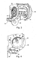
Figur 2 den Gurtaufroller vonFigur 1 in einer schematischen Seitenansicht; -
Figur 3 in einer Ansicht entsprechend derjenigen vonFigur 1 den Gurtaufroller mit fahrzeugsensitiv blockierter Gurtspule; -
Figur 4 den Gurtaufroller vonFigur 3 in einer Ansicht entsprechend derjenigen vonFigur 2 ; -
Figur 5 die Verzahnungsseite der Gurtspule; -
Figur 6 eine zweite Ausführungsform einer Gurtspule für einen erfindungsgemäßen Gurtaufroller; und -
Figur 7 eine Detailansicht der Steuerverzahnung der Gurtspule ausFigur 6 .
-
FIG. 1 in a schematic, perspective view of a belt retractor according to the invention in the initial state; -
FIG. 2 the belt retractor ofFIG. 1 in a schematic side view; -
FIG. 3 in a view corresponding to that ofFIG. 1 the belt retractor with vehicle-sensitive blocked belt reel; -
FIG. 4 the belt retractor ofFIG. 3 in a view corresponding to that ofFIG. 2 ; -
FIG. 5 the toothed side of the belt reel; -
FIG. 6 a second embodiment of a belt reel for a belt retractor according to the invention; and -
FIG. 7 a detailed view of the control toothing of the belt reelFIG. 6 ,
In den
An einem der beiden Flansche 20 der Gurtspule 14 ist, in axialer Richtung betrachtet; unmittelbar neben der Blockierverzahnung 24 eine Steuerverzahnung 26 ausgebildet, die hinsichtlich ihrer Teilung und ihrer Anordnung in Umfangsrichtung betrachtet mit der Blockierverzahnung 24 übereinstimmt. Der Unterschied zwischen der Blockierverzahnung 24 und der Steuerverzahnung 26 besteht insbesondere in der Geometrie der Zahnrücken, wie dies in
An einem der beiden Seitenteile 16 des Rahmens 12 des Gurtaufrollers 10 ist ein Steuerhebel 28 angeordnet, der nach Art einer Kappe die Steuerverzahnung 26 umgibt und mit einem Schwenkzapfen 30 schwenkbar am entsprechenden Seitenteil 16 des Rahmens 12 begrenzt schwenkbar angebracht ist. Der Steuerhebel 28 ist auf seiner Innenseite mit einer Innenverzahnung versehen, die für eine an sich bekannte gurtbandsensitive Blockierung der Gurtspule vorgesehen ist. Die Innenverzahnung und eine an der Gurtspule angeordnete Steuerklinke, die in die Innenverzahnung gurtbandsensitiv eingesteuert werden kann, sind hier nicht dargestellt.On one of the two
Für die fahrzeugsensitive Sperrung ist am Steuerhebel 28 ein Zwischenhebel 32 schwenkbar gelagert (siehe das Lager 33). Dieser kann aus der in den
Solange sich der Zwischenhebel 32 in der in den
Die Anordnung des Zwischenhebels 32 am Steuerhebel 28 gewährleistet dabei, dass die Zähne der Blockierverzahnung 24 lagerichtig in die Blockierzähne 22 am Rahmen 12 eingesteuert werden. Durch die reduzierte Zahnstärke der Steuerverzahnung 26 vergrößert sich die für die Einsteuerung des Zwischenhebels 32 verfügbare Bogenlänge bei gleichem Zahnabstand. Somit wird eine schnellere bzw. bessere Einsteuerung erreicht.The arrangement of the
Eine zweite Ausführungsform eines erfindungsgemäßen Gurtaufrollers 10 ist in den
Auf der dem Flansch 20 zugewandten Seite hat die Scheibe 46 mehrere in axialer Richtung abstehende Stege 48. Die Zähne der Steuerverzahnung 26 sind auf den Stegen 48 angeordnet. Des Weiteren sind an der Scheibe 46 mehrere Aussparungen 50 vorgesehen, die mit Vorsprüngen des Flansches 20, beispielsweise der Lagerung der Gurtspule 14, korrespondieren.On the side facing the
Zur Montage der Steuerverzahnung 26 beziehungsweise der Scheibe 46 wird die Scheibe 46 in axialer Richtung auf den Flansch 20 aufgesetzt, wobei die Aussparungen 50 auf entsprechende Vorsprünge des Flansches 20 aufgesetzt werden und die Stege 48 zwischen die Zähne der Blockierverzahnung 24 eingreifen. In montiertem Zustand liegen so die Blockierverzahnung 24 und die Steuerverzahnung 26 unmittelbar aneinander an.To mount the
Die Anordnung der Steuerverzahnung 26 auf einer separaten Scheibe 46 bietet den Vorteil, dass die Zähne der Steuerverzahnung 26 separat hergestellt werden können, wodurch eine größere Genauigkeit erzielt werden kann. Insbesondere können die Zähne der Steuerverzahnung annähernd radienfrei hergestellt werden können. Dies größere Genauigkeit bei der Herstellung der Steuerverzahnung 26 ermöglicht ein wesentlich exakteres Einsteuern des Zwischenhebels 32 und somit eine wesentlich genauere, weniger streuungsbehaftete Steuerung der Blockierung des Gurtaufrollers 10.The arrangement of the
Claims (12)
- A belt retractor (10) for a vehicle seat belt, comprising a frame (12) provided with a plurality of blocking teeth (22), a belt reel (14) being rotatably supported in the frame (12) and including a blocking tooth system (24) which is adapted to be engaged in the blocking teeth (22), a control lever (28) pivoted on the frame (12) and a sensor (34) which is triggered when a predetermined vehicle deceleration is exceeded, characterized in that the control lever (28) accommodates the belt reel (14) and in that a control tooth system (26) for interaction with the sensor (34) is provided at the belt reel (14).
- The belt retractor according to claim 1, characterized in that an intermediate lever (32) is provided which is adapted to be driven into the control tooth system (26) by the sensor (34).
- The belt retractor according to claim 2, characterized in that the intermediate lever (32) is supported on the control lever (28).
- The belt retractor according to any one of the preceding claims, characterized in that the blocking tooth system (24) and the control tooth system (26) are juxtaposed in the axial direction on a flange (20) of the belt reel (14).
- The belt retractor according to any one of the preceding claims, characterized in that the control tooth system (26) is arranged on a disk (46) which is retained to be rotationally fixed to the flange (20).
- The belt retractor according to claim 5, characterized in that lands (48) projecting from the disk (46) in the axial direction are provided which engage between the teeth of the blocking tooth system (24) in the axial direction, the control tooth system (26) being arranged especially on the lands (48).
- The belt retractor according to any one of the claims 4 to 6, characterized in that the blocking teeth (24) and the control teeth (26) have the same pitch and are arranged at the same orientation, wherein the teeth of the control tooth system (26) are designed to be more pointed than the teeth of the blocking tooth system (24).
- The belt retractor according to any one of the claims 4 to 7, characterized in that the blocking tooth system (24) and the control tooth system (26) have the same pitch and are arranged at the same orientation, the teeth of the control tooth system (26) being designed to be narrower than the teeth of the blocking tooth system (24).
- The belt retractor according to any one of the preceding claims, characterized in that the load-bearing sides (40) of the blocking tooth system (24) and the control tooth system (26) are designed to be identical and are aligned with each other and in that the opposed tooth faces (42, 44) of the blocking tooth system and the control tooth system are designed to be different from each other.
- The belt retractor according to any one of the preceding claims, characterized in that at the belt reel (14) a control pawl is provided which can be driven into an internal tooth system provided on the control lever (28) in a way sensitive to the webbing.
- The belt retractor according to any one of the preceding claims, characterized in that the tooth thickness of the control tooth system (26) is smaller than the tooth thickness of the blocking tooth system (24).
- The belt retractor according to any one of the preceding claims, characterized in that the frame (12) is provided with two side members (16) each being provided with blocking teeth (22), and in that the belt reel (14) is provided with a blocking tooth system (24) on each of the two axial sides.
Applications Claiming Priority (2)
| Application Number | Priority Date | Filing Date | Title |
|---|---|---|---|
| DE102011101965.4A DE102011101965B4 (en) | 2011-05-18 | 2011-05-18 | Belt retractor with control teeth |
| PCT/EP2012/002073 WO2012156074A1 (en) | 2011-05-18 | 2012-05-15 | Belt retractor with control toothing |
Publications (2)
| Publication Number | Publication Date |
|---|---|
| EP2709878A1 EP2709878A1 (en) | 2014-03-26 |
| EP2709878B1 true EP2709878B1 (en) | 2015-07-08 |
Family
ID=46354133
Family Applications (1)
| Application Number | Title | Priority Date | Filing Date |
|---|---|---|---|
| EP12729341.3A Active EP2709878B1 (en) | 2011-05-18 | 2012-05-15 | Belt retractor with control toothing |
Country Status (7)
| Country | Link |
|---|---|
| US (1) | US9283929B2 (en) |
| EP (1) | EP2709878B1 (en) |
| KR (1) | KR101988003B1 (en) |
| CN (1) | CN103619660B (en) |
| BR (1) | BR112013029662A2 (en) |
| DE (1) | DE102011101965B4 (en) |
| WO (1) | WO2012156074A1 (en) |
Families Citing this family (5)
| Publication number | Priority date | Publication date | Assignee | Title |
|---|---|---|---|---|
| JP5587159B2 (en) * | 2010-12-20 | 2014-09-10 | 株式会社東海理化電機製作所 | Webbing take-up device |
| DE102013004211B4 (en) * | 2013-03-12 | 2023-01-26 | Zf Automotive Germany Gmbh | belt retractor |
| CN104192092B (en) * | 2014-07-22 | 2016-08-31 | 常州市东晨车辆部件有限公司 | Seat belt wrap-up |
| US10166947B2 (en) * | 2015-10-15 | 2019-01-01 | Shield Restraint Systems, Inc. | Sealed web retractors for personal restraint systems and associated systems and methods |
| KR101803755B1 (en) * | 2016-05-25 | 2017-12-04 | 주식회사 우신세이프티시스템 | Intelligent Retractor Having Mode Changing Lever |
Family Cites Families (15)
| Publication number | Priority date | Publication date | Assignee | Title |
|---|---|---|---|---|
| DE2733008A1 (en) * | 1977-07-21 | 1979-02-01 | Kolb Gmbh & Co Hans | SAFETY BELT ROLLER DEVICE |
| DE2832159C2 (en) * | 1978-07-21 | 1986-11-27 | TRW Repa GmbH, 7077 Alfdorf | Seat belt retractors |
| DE2832160C2 (en) * | 1978-07-21 | 1984-09-06 | Repa Feinstanzwerk Gmbh, 7071 Alfdorf | Seat belt retractors |
| DE3043014A1 (en) * | 1980-11-14 | 1982-06-03 | Repa Feinstanzwerk Gmbh, 7071 Alfdorf | REELING MACHINE FOR A BELT |
| DE3421837A1 (en) | 1984-02-16 | 1985-12-12 | Hans-Hellmut Dipl.-Ing. 2061 Sülfeld Ernst | Arresting apparatus for a safety belt |
| DE3421960C2 (en) | 1984-06-13 | 1991-10-31 | Britax-Kolb GmbH & Co, 8065 Erdweg | Belt retractor and locking mechanism |
| GB2247154A (en) * | 1990-08-08 | 1992-02-26 | Europ Components Corp | Safety belt retractor for a vehicle |
| JP2951735B2 (en) * | 1991-03-11 | 1999-09-20 | タカタ株式会社 | Seat belt retractor |
| DE4314883A1 (en) | 1993-05-05 | 1994-11-10 | Trw Repa Gmbh | Seat belt retractor |
| DE19524162A1 (en) * | 1995-07-03 | 1997-01-09 | Trw Repa Gmbh | Belt retractor for a seat belt |
| JP3947064B2 (en) * | 2002-08-29 | 2007-07-18 | 株式会社東海理化電機製作所 | Webbing take-up device |
| DE10358561A1 (en) * | 2003-12-15 | 2005-08-04 | Trw Occupant Restraint Systems Gmbh & Co. Kg | Belt retractor for a vehicle seat belt |
| JP2006137290A (en) * | 2004-11-11 | 2006-06-01 | Tokai Rika Co Ltd | Webbing take-up device |
| DE102005029487B4 (en) * | 2005-06-24 | 2008-11-06 | Autoliv Development Ab | Seat belt retractor with an adjustable sensor, which can only be moved when the webbing is retracted |
| KR101803755B1 (en) | 2016-05-25 | 2017-12-04 | 주식회사 우신세이프티시스템 | Intelligent Retractor Having Mode Changing Lever |
-
2011
- 2011-05-18 DE DE102011101965.4A patent/DE102011101965B4/en active Active
-
2012
- 2012-05-15 CN CN201280031534.XA patent/CN103619660B/en active Active
- 2012-05-15 WO PCT/EP2012/002073 patent/WO2012156074A1/en active Application Filing
- 2012-05-15 BR BR112013029662-3A patent/BR112013029662A2/en not_active Application Discontinuation
- 2012-05-15 EP EP12729341.3A patent/EP2709878B1/en active Active
- 2012-05-15 KR KR1020137032417A patent/KR101988003B1/en active IP Right Grant
- 2012-05-15 US US14/117,896 patent/US9283929B2/en active Active
Also Published As
| Publication number | Publication date |
|---|---|
| EP2709878A1 (en) | 2014-03-26 |
| KR20140029481A (en) | 2014-03-10 |
| DE102011101965B4 (en) | 2022-07-14 |
| US9283929B2 (en) | 2016-03-15 |
| CN103619660B (en) | 2016-11-23 |
| BR112013029662A2 (en) | 2020-10-27 |
| CN103619660A (en) | 2014-03-05 |
| WO2012156074A1 (en) | 2012-11-22 |
| KR101988003B1 (en) | 2019-06-11 |
| US20140091167A1 (en) | 2014-04-03 |
| DE102011101965A1 (en) | 2012-11-22 |
Similar Documents
| Publication | Publication Date | Title |
|---|---|---|
| DE2254003C2 (en) | Seat belt retractor with strain relief | |
| DE2452419A1 (en) | DEVICE FOR LOCKING AN AXLE | |
| EP2709878B1 (en) | Belt retractor with control toothing | |
| DE2646238A1 (en) | BELT ROLLERS FOR VEHICLE SAFETY BELTS WITH BLOCKING DEVICE | |
| DE2234116A1 (en) | RETRACTING DEVICE FOR SAFETY BELTS | |
| DE3520915C2 (en) | ||
| DE19820641B4 (en) | Gurtaufwickeleinrichtung | |
| DE1531511B2 (en) | Safety lock for a belt retractor | |
| DE4302739C2 (en) | Seat belt retractor | |
| DE4307012C2 (en) | Seat belt retractor | |
| DE3715846A1 (en) | SAFETY BELT REEL WITH REVOLUTION DEVICE | |
| DE102007020000A1 (en) | retractor | |
| DE4311201C2 (en) | Seat belt retractor with clamping device | |
| EP0152909B1 (en) | Automatic retraction device for a vehicle safety belt | |
| DE2553642A1 (en) | ROLLING DEVICE, IN PARTICULAR FOR SAFETY BELTS IN VEHICLES | |
| DE3933453A1 (en) | BELT REEL | |
| DE4302707A1 (en) | ||
| DE3627715C2 (en) | ||
| WO2014139658A1 (en) | Belt retractor | |
| EP0952048B1 (en) | Seat belt retractor for a safety belt restraint system | |
| EP1285827B1 (en) | Seat belt retractor for a vehicle seat belt | |
| DE10352025B4 (en) | retractor | |
| EP3669848B1 (en) | Retractor restraint system, method and use of such a system, in particular for securing wheelchairs in vehicles | |
| DE10213248A1 (en) | Roller mechanism fitted in road vehicle for taking up seat belt has spool with pawls engaging sawtooth teeth on framework | |
| DE4001240C2 (en) | Locking device for belt retractor |
Legal Events
| Date | Code | Title | Description |
|---|---|---|---|
| PUAI | Public reference made under article 153(3) epc to a published international application that has entered the european phase |
Free format text: ORIGINAL CODE: 0009012 |
|
| 17P | Request for examination filed |
Effective date: 20131113 |
|
| AK | Designated contracting states |
Kind code of ref document: A1 Designated state(s): AL AT BE BG CH CY CZ DE DK EE ES FI FR GB GR HR HU IE IS IT LI LT LU LV MC MK MT NL NO PL PT RO RS SE SI SK SM TR |
|
| RIN1 | Information on inventor provided before grant (corrected) |
Inventor name: DAEUBER, MARKUS Inventor name: KIELWEIN, THOMAS Inventor name: SEHIC, DEMAL Inventor name: SIEBECK, BORIS Inventor name: RINK, JUERGEN Inventor name: ADOMEIT, JULIUS Inventor name: MUECKE, CHRISTIAN |
|
| DAX | Request for extension of the european patent (deleted) | ||
| REG | Reference to a national code |
Ref country code: DE Ref legal event code: R079 Ref document number: 502012003741 Country of ref document: DE Free format text: PREVIOUS MAIN CLASS: B60R0022405000 Ipc: B60R0022400000 |
|
| RIC1 | Information provided on ipc code assigned before grant |
Ipc: B60R 22/40 20060101AFI20141030BHEP Ipc: B60R 22/405 20060101ALI20141030BHEP |
|
| GRAP | Despatch of communication of intention to grant a patent |
Free format text: ORIGINAL CODE: EPIDOSNIGR1 |
|
| INTG | Intention to grant announced |
Effective date: 20150108 |
|
| GRAS | Grant fee paid |
Free format text: ORIGINAL CODE: EPIDOSNIGR3 |
|
| GRAA | (expected) grant |
Free format text: ORIGINAL CODE: 0009210 |
|
| AK | Designated contracting states |
Kind code of ref document: B1 Designated state(s): AL AT BE BG CH CY CZ DE DK EE ES FI FR GB GR HR HU IE IS IT LI LT LU LV MC MK MT NL NO PL PT RO RS SE SI SK SM TR |
|
| REG | Reference to a national code |
Ref country code: GB Ref legal event code: FG4D Free format text: NOT ENGLISH |
|
| REG | Reference to a national code |
Ref country code: AT Ref legal event code: REF Ref document number: 735135 Country of ref document: AT Kind code of ref document: T Effective date: 20150715 Ref country code: CH Ref legal event code: EP |
|
| REG | Reference to a national code |
Ref country code: IE Ref legal event code: FG4D Free format text: LANGUAGE OF EP DOCUMENT: GERMAN |
|
| REG | Reference to a national code |
Ref country code: DE Ref legal event code: R096 Ref document number: 502012003741 Country of ref document: DE |
|
| REG | Reference to a national code |
Ref country code: NL Ref legal event code: MP Effective date: 20150708 |
|
| REG | Reference to a national code |
Ref country code: LT Ref legal event code: MG4D |
|
| PG25 | Lapsed in a contracting state [announced via postgrant information from national office to epo] |
Ref country code: LT Free format text: LAPSE BECAUSE OF FAILURE TO SUBMIT A TRANSLATION OF THE DESCRIPTION OR TO PAY THE FEE WITHIN THE PRESCRIBED TIME-LIMIT Effective date: 20150708 Ref country code: LV Free format text: LAPSE BECAUSE OF FAILURE TO SUBMIT A TRANSLATION OF THE DESCRIPTION OR TO PAY THE FEE WITHIN THE PRESCRIBED TIME-LIMIT Effective date: 20150708 Ref country code: NO Free format text: LAPSE BECAUSE OF FAILURE TO SUBMIT A TRANSLATION OF THE DESCRIPTION OR TO PAY THE FEE WITHIN THE PRESCRIBED TIME-LIMIT Effective date: 20151008 Ref country code: FI Free format text: LAPSE BECAUSE OF FAILURE TO SUBMIT A TRANSLATION OF THE DESCRIPTION OR TO PAY THE FEE WITHIN THE PRESCRIBED TIME-LIMIT Effective date: 20150708 Ref country code: GR Free format text: LAPSE BECAUSE OF FAILURE TO SUBMIT A TRANSLATION OF THE DESCRIPTION OR TO PAY THE FEE WITHIN THE PRESCRIBED TIME-LIMIT Effective date: 20151009 |
|
| PG25 | Lapsed in a contracting state [announced via postgrant information from national office to epo] |
Ref country code: HR Free format text: LAPSE BECAUSE OF FAILURE TO SUBMIT A TRANSLATION OF THE DESCRIPTION OR TO PAY THE FEE WITHIN THE PRESCRIBED TIME-LIMIT Effective date: 20150708 Ref country code: PT Free format text: LAPSE BECAUSE OF FAILURE TO SUBMIT A TRANSLATION OF THE DESCRIPTION OR TO PAY THE FEE WITHIN THE PRESCRIBED TIME-LIMIT Effective date: 20151109 Ref country code: SE Free format text: LAPSE BECAUSE OF FAILURE TO SUBMIT A TRANSLATION OF THE DESCRIPTION OR TO PAY THE FEE WITHIN THE PRESCRIBED TIME-LIMIT Effective date: 20150708 Ref country code: RS Free format text: LAPSE BECAUSE OF FAILURE TO SUBMIT A TRANSLATION OF THE DESCRIPTION OR TO PAY THE FEE WITHIN THE PRESCRIBED TIME-LIMIT Effective date: 20150708 Ref country code: IS Free format text: LAPSE BECAUSE OF FAILURE TO SUBMIT A TRANSLATION OF THE DESCRIPTION OR TO PAY THE FEE WITHIN THE PRESCRIBED TIME-LIMIT Effective date: 20151108 Ref country code: PL Free format text: LAPSE BECAUSE OF FAILURE TO SUBMIT A TRANSLATION OF THE DESCRIPTION OR TO PAY THE FEE WITHIN THE PRESCRIBED TIME-LIMIT Effective date: 20150708 Ref country code: ES Free format text: LAPSE BECAUSE OF FAILURE TO SUBMIT A TRANSLATION OF THE DESCRIPTION OR TO PAY THE FEE WITHIN THE PRESCRIBED TIME-LIMIT Effective date: 20150708 |
|
| REG | Reference to a national code |
Ref country code: DE Ref legal event code: R097 Ref document number: 502012003741 Country of ref document: DE |
|
| PG25 | Lapsed in a contracting state [announced via postgrant information from national office to epo] |
Ref country code: DK Free format text: LAPSE BECAUSE OF FAILURE TO SUBMIT A TRANSLATION OF THE DESCRIPTION OR TO PAY THE FEE WITHIN THE PRESCRIBED TIME-LIMIT Effective date: 20150708 Ref country code: SK Free format text: LAPSE BECAUSE OF FAILURE TO SUBMIT A TRANSLATION OF THE DESCRIPTION OR TO PAY THE FEE WITHIN THE PRESCRIBED TIME-LIMIT Effective date: 20150708 Ref country code: EE Free format text: LAPSE BECAUSE OF FAILURE TO SUBMIT A TRANSLATION OF THE DESCRIPTION OR TO PAY THE FEE WITHIN THE PRESCRIBED TIME-LIMIT Effective date: 20150708 Ref country code: CZ Free format text: LAPSE BECAUSE OF FAILURE TO SUBMIT A TRANSLATION OF THE DESCRIPTION OR TO PAY THE FEE WITHIN THE PRESCRIBED TIME-LIMIT Effective date: 20150708 |
|
| PLBE | No opposition filed within time limit |
Free format text: ORIGINAL CODE: 0009261 |
|
| STAA | Information on the status of an ep patent application or granted ep patent |
Free format text: STATUS: NO OPPOSITION FILED WITHIN TIME LIMIT |
|
| REG | Reference to a national code |
Ref country code: FR Ref legal event code: PLFP Year of fee payment: 5 |
|
| PG25 | Lapsed in a contracting state [announced via postgrant information from national office to epo] |
Ref country code: RO Free format text: LAPSE BECAUSE OF FAILURE TO SUBMIT A TRANSLATION OF THE DESCRIPTION OR TO PAY THE FEE WITHIN THE PRESCRIBED TIME-LIMIT Effective date: 20150708 |
|
| 26N | No opposition filed |
Effective date: 20160411 |
|
| PG25 | Lapsed in a contracting state [announced via postgrant information from national office to epo] |
Ref country code: BE Free format text: LAPSE BECAUSE OF NON-PAYMENT OF DUE FEES Effective date: 20160531 Ref country code: SI Free format text: LAPSE BECAUSE OF FAILURE TO SUBMIT A TRANSLATION OF THE DESCRIPTION OR TO PAY THE FEE WITHIN THE PRESCRIBED TIME-LIMIT Effective date: 20150708 |
|
| PG25 | Lapsed in a contracting state [announced via postgrant information from national office to epo] |
Ref country code: LU Free format text: LAPSE BECAUSE OF FAILURE TO SUBMIT A TRANSLATION OF THE DESCRIPTION OR TO PAY THE FEE WITHIN THE PRESCRIBED TIME-LIMIT Effective date: 20160515 |
|
| REG | Reference to a national code |
Ref country code: CH Ref legal event code: PL |
|
| GBPC | Gb: european patent ceased through non-payment of renewal fee |
Effective date: 20160515 |
|
| PG25 | Lapsed in a contracting state [announced via postgrant information from national office to epo] |
Ref country code: CH Free format text: LAPSE BECAUSE OF NON-PAYMENT OF DUE FEES Effective date: 20160531 Ref country code: LI Free format text: LAPSE BECAUSE OF NON-PAYMENT OF DUE FEES Effective date: 20160531 |
|
| REG | Reference to a national code |
Ref country code: IE Ref legal event code: MM4A |
|
| REG | Reference to a national code |
Ref country code: FR Ref legal event code: PLFP Year of fee payment: 6 |
|
| PG25 | Lapsed in a contracting state [announced via postgrant information from national office to epo] |
Ref country code: GB Free format text: LAPSE BECAUSE OF NON-PAYMENT OF DUE FEES Effective date: 20160515 Ref country code: IE Free format text: LAPSE BECAUSE OF NON-PAYMENT OF DUE FEES Effective date: 20160515 |
|
| PG25 | Lapsed in a contracting state [announced via postgrant information from national office to epo] |
Ref country code: NL Free format text: LAPSE BECAUSE OF FAILURE TO SUBMIT A TRANSLATION OF THE DESCRIPTION OR TO PAY THE FEE WITHIN THE PRESCRIBED TIME-LIMIT Effective date: 20150708 |
|
| REG | Reference to a national code |
Ref country code: FR Ref legal event code: PLFP Year of fee payment: 7 |
|
| PG25 | Lapsed in a contracting state [announced via postgrant information from national office to epo] |
Ref country code: HU Free format text: LAPSE BECAUSE OF FAILURE TO SUBMIT A TRANSLATION OF THE DESCRIPTION OR TO PAY THE FEE WITHIN THE PRESCRIBED TIME-LIMIT; INVALID AB INITIO Effective date: 20120515 Ref country code: CY Free format text: LAPSE BECAUSE OF FAILURE TO SUBMIT A TRANSLATION OF THE DESCRIPTION OR TO PAY THE FEE WITHIN THE PRESCRIBED TIME-LIMIT Effective date: 20150708 Ref country code: SM Free format text: LAPSE BECAUSE OF FAILURE TO SUBMIT A TRANSLATION OF THE DESCRIPTION OR TO PAY THE FEE WITHIN THE PRESCRIBED TIME-LIMIT Effective date: 20150708 |
|
| PG25 | Lapsed in a contracting state [announced via postgrant information from national office to epo] |
Ref country code: MC Free format text: LAPSE BECAUSE OF FAILURE TO SUBMIT A TRANSLATION OF THE DESCRIPTION OR TO PAY THE FEE WITHIN THE PRESCRIBED TIME-LIMIT Effective date: 20150708 Ref country code: TR Free format text: LAPSE BECAUSE OF FAILURE TO SUBMIT A TRANSLATION OF THE DESCRIPTION OR TO PAY THE FEE WITHIN THE PRESCRIBED TIME-LIMIT Effective date: 20150708 Ref country code: MT Free format text: LAPSE BECAUSE OF FAILURE TO SUBMIT A TRANSLATION OF THE DESCRIPTION OR TO PAY THE FEE WITHIN THE PRESCRIBED TIME-LIMIT Effective date: 20150708 Ref country code: MK Free format text: LAPSE BECAUSE OF FAILURE TO SUBMIT A TRANSLATION OF THE DESCRIPTION OR TO PAY THE FEE WITHIN THE PRESCRIBED TIME-LIMIT Effective date: 20150708 |
|
| REG | Reference to a national code |
Ref country code: AT Ref legal event code: MM01 Ref document number: 735135 Country of ref document: AT Kind code of ref document: T Effective date: 20170515 |
|
| PG25 | Lapsed in a contracting state [announced via postgrant information from national office to epo] |
Ref country code: BG Free format text: LAPSE BECAUSE OF FAILURE TO SUBMIT A TRANSLATION OF THE DESCRIPTION OR TO PAY THE FEE WITHIN THE PRESCRIBED TIME-LIMIT Effective date: 20150708 |
|
| PG25 | Lapsed in a contracting state [announced via postgrant information from national office to epo] |
Ref country code: AT Free format text: LAPSE BECAUSE OF NON-PAYMENT OF DUE FEES Effective date: 20170515 |
|
| PG25 | Lapsed in a contracting state [announced via postgrant information from national office to epo] |
Ref country code: AL Free format text: LAPSE BECAUSE OF FAILURE TO SUBMIT A TRANSLATION OF THE DESCRIPTION OR TO PAY THE FEE WITHIN THE PRESCRIBED TIME-LIMIT Effective date: 20150708 |
|
| REG | Reference to a national code |
Ref country code: DE Ref legal event code: R081 Ref document number: 502012003741 Country of ref document: DE Owner name: ZF AUTOMOTIVE GERMANY GMBH, DE Free format text: FORMER OWNER: TRW AUTOMOTIVE GMBH, 73553 ALFDORF, DE |
|
| PGFP | Annual fee paid to national office [announced via postgrant information from national office to epo] |
Ref country code: FR Payment date: 20230309 Year of fee payment: 12 |
|
| PGFP | Annual fee paid to national office [announced via postgrant information from national office to epo] |
Ref country code: IT Payment date: 20230412 Year of fee payment: 12 Ref country code: DE Payment date: 20230531 Year of fee payment: 12 |
|
| P01 | Opt-out of the competence of the unified patent court (upc) registered |
Effective date: 20230628 |