EP2709570B1 - An orthotic insole - Google Patents
An orthotic insole Download PDFInfo
- Publication number
- EP2709570B1 EP2709570B1 EP12720179.6A EP12720179A EP2709570B1 EP 2709570 B1 EP2709570 B1 EP 2709570B1 EP 12720179 A EP12720179 A EP 12720179A EP 2709570 B1 EP2709570 B1 EP 2709570B1
- Authority
- EP
- European Patent Office
- Prior art keywords
- insole
- shoe
- extension portion
- foot
- cut away
- Prior art date
- Legal status (The legal status is an assumption and is not a legal conclusion. Google has not performed a legal analysis and makes no representation as to the accuracy of the status listed.)
- Not-in-force
Links
- 239000000463 material Substances 0.000 claims description 10
- RYGMFSIKBFXOCR-UHFFFAOYSA-N Copper Chemical compound [Cu] RYGMFSIKBFXOCR-UHFFFAOYSA-N 0.000 claims description 3
- 239000004743 Polypropylene Substances 0.000 claims description 3
- 238000010276 construction Methods 0.000 claims description 3
- 229910052802 copper Inorganic materials 0.000 claims description 3
- 239000010949 copper Substances 0.000 claims description 3
- -1 polypropylene Polymers 0.000 claims description 3
- 229920001155 polypropylene Polymers 0.000 claims description 3
- 230000000717 retained effect Effects 0.000 claims description 3
- 239000011800 void material Substances 0.000 claims description 3
- 210000002683 foot Anatomy 0.000 description 30
- 210000003195 fascia Anatomy 0.000 description 15
- 210000003041 ligament Anatomy 0.000 description 14
- 210000000474 heel Anatomy 0.000 description 12
- 210000000459 calcaneus Anatomy 0.000 description 11
- 210000001872 metatarsal bone Anatomy 0.000 description 11
- 210000002435 tendon Anatomy 0.000 description 7
- 230000005021 gait Effects 0.000 description 4
- 210000004872 soft tissue Anatomy 0.000 description 4
- 210000003371 toe Anatomy 0.000 description 3
- 210000000988 bone and bone Anatomy 0.000 description 2
- 230000001771 impaired effect Effects 0.000 description 2
- 238000003780 insertion Methods 0.000 description 2
- 230000037431 insertion Effects 0.000 description 2
- 230000001141 propulsive effect Effects 0.000 description 2
- 210000004233 talus Anatomy 0.000 description 2
- 208000003643 Callosities Diseases 0.000 description 1
- 206010020649 Hyperkeratosis Diseases 0.000 description 1
- 210000003423 ankle Anatomy 0.000 description 1
- 210000000549 articulatio subtalaris Anatomy 0.000 description 1
- 230000001174 ascending effect Effects 0.000 description 1
- 230000015572 biosynthetic process Effects 0.000 description 1
- 210000001255 hallux Anatomy 0.000 description 1
- 230000035876 healing Effects 0.000 description 1
- 210000000859 intermediate cuneiform Anatomy 0.000 description 1
- 210000000705 lateral cuneiform Anatomy 0.000 description 1
- 210000000113 medial cuneiform Anatomy 0.000 description 1
- 230000007721 medicinal effect Effects 0.000 description 1
- 210000000878 metatarsophalangeal joint Anatomy 0.000 description 1
- 238000000034 method Methods 0.000 description 1
- 210000000452 mid-foot Anatomy 0.000 description 1
- 210000003205 muscle Anatomy 0.000 description 1
- 230000001575 pathological effect Effects 0.000 description 1
- 239000004033 plastic Substances 0.000 description 1
- 229920000642 polymer Polymers 0.000 description 1
- 230000003319 supportive effect Effects 0.000 description 1
- 238000004804 winding Methods 0.000 description 1
Images


Classifications
-
- A—HUMAN NECESSITIES
- A43—FOOTWEAR
- A43B—CHARACTERISTIC FEATURES OF FOOTWEAR; PARTS OF FOOTWEAR
- A43B13/00—Soles; Sole-and-heel integral units
- A43B13/38—Built-in insoles joined to uppers during the manufacturing process, e.g. structural insoles; Insoles glued to shoes during the manufacturing process
- A43B13/41—Built-in insoles joined to uppers during the manufacturing process, e.g. structural insoles; Insoles glued to shoes during the manufacturing process combined with heel stiffener, toe stiffener, or shank stiffener
-
- A—HUMAN NECESSITIES
- A43—FOOTWEAR
- A43B—CHARACTERISTIC FEATURES OF FOOTWEAR; PARTS OF FOOTWEAR
- A43B7/00—Footwear with health or hygienic arrangements
- A43B7/14—Footwear with health or hygienic arrangements with foot-supporting parts
- A43B7/1405—Footwear with health or hygienic arrangements with foot-supporting parts with pads or holes on one or more locations, or having an anatomical or curved form
- A43B7/1415—Footwear with health or hygienic arrangements with foot-supporting parts with pads or holes on one or more locations, or having an anatomical or curved form characterised by the location under the foot
- A43B7/144—Footwear with health or hygienic arrangements with foot-supporting parts with pads or holes on one or more locations, or having an anatomical or curved form characterised by the location under the foot situated under the heel, i.e. the calcaneus bone
-
- A—HUMAN NECESSITIES
- A43—FOOTWEAR
- A43B—CHARACTERISTIC FEATURES OF FOOTWEAR; PARTS OF FOOTWEAR
- A43B7/00—Footwear with health or hygienic arrangements
- A43B7/14—Footwear with health or hygienic arrangements with foot-supporting parts
- A43B7/1405—Footwear with health or hygienic arrangements with foot-supporting parts with pads or holes on one or more locations, or having an anatomical or curved form
- A43B7/141—Footwear with health or hygienic arrangements with foot-supporting parts with pads or holes on one or more locations, or having an anatomical or curved form having an anatomical or curved form
-
- A—HUMAN NECESSITIES
- A43—FOOTWEAR
- A43B—CHARACTERISTIC FEATURES OF FOOTWEAR; PARTS OF FOOTWEAR
- A43B13/00—Soles; Sole-and-heel integral units
- A43B13/38—Built-in insoles joined to uppers during the manufacturing process, e.g. structural insoles; Insoles glued to shoes during the manufacturing process
-
- A—HUMAN NECESSITIES
- A43—FOOTWEAR
- A43B—CHARACTERISTIC FEATURES OF FOOTWEAR; PARTS OF FOOTWEAR
- A43B7/00—Footwear with health or hygienic arrangements
- A43B7/14—Footwear with health or hygienic arrangements with foot-supporting parts
- A43B7/1405—Footwear with health or hygienic arrangements with foot-supporting parts with pads or holes on one or more locations, or having an anatomical or curved form
- A43B7/1415—Footwear with health or hygienic arrangements with foot-supporting parts with pads or holes on one or more locations, or having an anatomical or curved form characterised by the location under the foot
- A43B7/142—Footwear with health or hygienic arrangements with foot-supporting parts with pads or holes on one or more locations, or having an anatomical or curved form characterised by the location under the foot situated under the medial arch, i.e. under the navicular or cuneiform bones
-
- A—HUMAN NECESSITIES
- A43—FOOTWEAR
- A43B—CHARACTERISTIC FEATURES OF FOOTWEAR; PARTS OF FOOTWEAR
- A43B7/00—Footwear with health or hygienic arrangements
- A43B7/14—Footwear with health or hygienic arrangements with foot-supporting parts
- A43B7/1405—Footwear with health or hygienic arrangements with foot-supporting parts with pads or holes on one or more locations, or having an anatomical or curved form
- A43B7/1475—Footwear with health or hygienic arrangements with foot-supporting parts with pads or holes on one or more locations, or having an anatomical or curved form characterised by the type of support
- A43B7/149—Pads, e.g. protruding on the foot-facing surface
-
- A—HUMAN NECESSITIES
- A43—FOOTWEAR
- A43B—CHARACTERISTIC FEATURES OF FOOTWEAR; PARTS OF FOOTWEAR
- A43B7/00—Footwear with health or hygienic arrangements
- A43B7/14—Footwear with health or hygienic arrangements with foot-supporting parts
- A43B7/22—Footwear with health or hygienic arrangements with foot-supporting parts with fixed flat-foot insertions, metatarsal supports, ankle flaps or the like
- A43B7/223—Footwear with health or hygienic arrangements with foot-supporting parts with fixed flat-foot insertions, metatarsal supports, ankle flaps or the like characterised by the constructive form
-
- A—HUMAN NECESSITIES
- A61—MEDICAL OR VETERINARY SCIENCE; HYGIENE
- A61F—FILTERS IMPLANTABLE INTO BLOOD VESSELS; PROSTHESES; DEVICES PROVIDING PATENCY TO, OR PREVENTING COLLAPSING OF, TUBULAR STRUCTURES OF THE BODY, e.g. STENTS; ORTHOPAEDIC, NURSING OR CONTRACEPTIVE DEVICES; FOMENTATION; TREATMENT OR PROTECTION OF EYES OR EARS; BANDAGES, DRESSINGS OR ABSORBENT PADS; FIRST-AID KITS
- A61F5/00—Orthopaedic methods or devices for non-surgical treatment of bones or joints; Nursing devices ; Anti-rape devices
- A61F5/01—Orthopaedic devices, e.g. long-term immobilising or pressure directing devices for treating broken or deformed bones such as splints, casts or braces
- A61F5/14—Special medical insertions for shoes for flat-feet, club-feet or the like
Definitions
- the present invention relates to an orthotic insole and in particular to an orthotic insole that can be inserted into an existing shoe.
- an orthotic insole in accordance with the present invention may also be used as an integral part of the construction of a shoe.
- insoles, orthotics and arch supports work on the premise that the instep, medical longitudinal arch, or natural arch of the foot requires support and this is achieved by physically filling the natural arch of the foot.
- the instep is therefore fully supported by one or more of a variety of materials, which control and support the foot function by infill of the arches. These devices are tolerated, but may take time to adjust to the foot. Also due to the necessity of width and length they are sometimes difficult to accommodate into footwear.
- orthotic insoles are disclosed, for example, in U2821032, US2008/0217816 A1 , and DE895045 .
- an orthotic insole according to the preamble of appended claim 1 is disclosed in US3828792 .
- the invention seeks to aid this propulsive movement by enabling and not obstructing the medial longitudinal arch component.
- Still another object of the invention is to provide an insole which can more easily fit into footwear and improve shoe wearer comfort.
- an orthotic insole as disclosed in claim 1 namely comprising a cupped heel plate and an extension portion extending forward of the heel plate and terminating in the region of the talonavicular junction on the plantar aspect of the foot, the extension portion being cut away in both a lateral portion and a medial portion, so that the extension portion forms a central spur.
- cut away is used to describe the shape of the insole and does not relate to the method of forming the "cut away” portions.
- the insole will preferably be designed for either the right or left foot, wherein the medial portion is more extensively cut away than the lateral portion.
- the present invention provides an insole which may be inserted into a shoe or which alternatively may be integral with the structure of the shoe.
- the heel plate is generally configured in the shape of a cupped heel base to the calcaneum area, so that the centrally placed extension of the insole extends to the soft tissue junction of the talar navicular joint and is retained in place below the talar navicular joint by the shape of the heel portion being retained in place by the shoe and the wearer heel.
- An insole in accordance with the present invention supports and facilitates motion and alignment of the arches of the foot by the application of a dorsiflexory force, a force applied in an upward direction, to a defined central area whilst facilitating medial and lateral movement of the foot by only primarily supporting the central portion of the calcaneum (heel bone) and plantar aponeurosis (plantar fascia) from its origin at the calcaneum tuberosity.
- the plantar fascia tendon has three distinct segments; medial, central and lateral.
- medial For normal gait patterns the requirement is for the foot to pass through the fulcrum of force and momentum in a centrally, symmetrically manner for the most appropriate mechanics, because normal foot motion requires a balance between pronation and supination throughout the gait or walking cycle, where any deviance to the lateral is referred to as supination and any deviance to the medial is referred to as pronation.
- the central ligament of the plantar fascia has its origin from the calcaneus (heel bone) and the three segments to the plantar fascia run under the transverse arch consisting of cuboid, navicular and cuneiforms. The plantar fascia then inserts into the distal phalanges of the toes as tendon slips.
- the central portion of soft tissues and skeletal structures is supported facilitating improved effective foot motion and improved weight bearing of the foot instep whilst permitting normal functioning of the plantar fascia tendon including the "windlass mechanism". Also by placing a supportive uplift to the central portion of the soft tissue, the skeletal structures terminating at the talonavicular joint, an insole in accordance with the present invention results in the ease of pressure on the distal aspects of the weight bearing aspects of the metatarsals.
- the cut away portions of the insole preferably with more insole material on the medial side being absent than on the lateral side, facilitates the normal motion of the central ligaments and the transverse keystone arch of the foot.
- the insole may be formed from a polypropylene material and advantageously comprises a single homogenous structure.
- the composition of the insole may comprise copper, known to have healing properties.
- the material of the insole is preferably a semi-rigid material.
- the distal end of the extension portion of the insole curves downwards, such that the extension portion forms an arch with a void below the arch, thereby permitting the extension portion to flex when inserted into a shoe and weight is applied to the upper surface of the insole, permitting a more constant force to be applied by the extension portion to the foot than would be the case if the there was not a void below the extension portion.
- the insole is dimensioned such that 80% of the area of the insole has a thickness of between 3 and 5 mm, enabling it to be accommodated in a shoe and to provide the required rigidity.
- a central portion in the length direction of the extension portion is between 40% and 60% of the maximum width of the insole.
- the medial portion is cut away by more than 25%, but less than 40% of the maximum width of the insole and/or that the lateral portion is cut away by more 15% but less than 30% of the maximum width of the insole.
- the insole preferably has a total length of between 100 and 150 mm, such that it terminates in the region of the talonavicular junction of the foot of a wearer.
- an insole indicated generally as 1, in accordance with the present invention is preferably constructed as a homogenous semi-flexible to rigid plastic polymer, for example polypropylene, to which copper may be added for its known medical properties.
- the insole comprises a heel plate 2, preferably in the shape of a heel cup base to the calcaneum area, with a central extension portion extending forward of the heel plate 2, the central portion 3, being cut away at a lateral portion 4 and medial portion 5 so that the extension portion 3 is in the form of a central band.
- the distal end 6 of the extension portion curves downwards in the region 6 so that its lower surface forms an arch in the region 7 which arch can be compressed when weight is applied to the upper surface of the insole 1.
- the insole 1 has a length A preferably between 100 and 150 mm.
- the insole 1 has a maximum width B in the heel plate region of between 50 to 70 mm, with the insole having a thickness of preferably between 3 and 5 mm over at least 80% of its area.
- the extension portion 3 at a point midway between the widest point of the insole and the distal end of the extension portion has a width C of between 40% and 60% of a maximum width B of the insole.
- the medial portion is preferably cut away by an amount D greater than 25%, but less than 40% of the maximum width B of the insole.
- the lateral portion is preferably cut away at this point by a width E of more than 15%, but less than 30% of the maximum width B of the insole.
- FIG. 2 there is illustrated a plantar view of the bones of the foot comprising the phalanges 8, sesamoids 9, metatarsals 10, the medial cuneiform 11, the intermediate cuneiform 12, the lateral cuneiform 13, cuboid 14, navicular 15, talus 16 and calcaneum 17.
- the insole 1 is shown superimposed on the plantar supporting the calcaneum 17 and extending to the region of the talus navicular joint 18.
- Figure 3 illustrates the plantar ligaments of the foot comprising the long plantar ligament 19, the plantar calcaneonavicular ligament (the spring ligament) 20 and the short plantar ligament 21.
- the insole 1 is shown superimposed over the plantar ligaments and is seen to extend to the region of the talar navicular junction 18 in the region below the long plantar and short plantar ligaments.
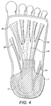
- FIG. 4 there is illustrated the position of the insole 1 relative to the plantar fascia, indicated generally as 22 and comprising a central portion 23, a lateral portion 24 and a medial portion 25.
- the lateral portion 23 being inserted into the digital slips in the region 26.
- the insole can be seen to support the central portion of the plantar fascia distal to its insertion to the calcaneum, terminating at the talar navicular joint. Just proximal to the ascending transverse arch.
- Supporting the ligaments as illustrated causes the ligaments to be supported at the biomechanical moment of transfer of weight from heel strike to midfoot loading.
- first metatarsal and cuneiform section first metatarsal and cuneiform section
- lateral ray 5 th and 4 th metatarsal complexes
- the absence of the medial and lateral portions of the insole permits the deep ligaments to the first ray (first metatarsal and cuneiform section) and the lateral ray (5 th and 4 th metatarsal complexes) to move without impingement from orthotic material.
- This arrangement is advantageous because it permits normal plantarflexion and dorsiflexion movement of the first ray mechanics (first metatarsal and cuneiform section) and the lateral ray (5 th and 4 th metatarsal complexes) without impingement from orthotic material (in individual optimal mode). It also permits active engagement of the lesser metatarsals and the first ray on the pivot point to be centrally supported by the insole.
- the insole has been illustrated in the previous drawings by way of example as a separate insole to be inserted into a shoe.
- a shoe may comprise such an insert within the construction of the shoe.
Landscapes
- Health & Medical Sciences (AREA)
- General Health & Medical Sciences (AREA)
- Public Health (AREA)
- Epidemiology (AREA)
- Engineering & Computer Science (AREA)
- Orthopedic Medicine & Surgery (AREA)
- Nursing (AREA)
- Biomedical Technology (AREA)
- Heart & Thoracic Surgery (AREA)
- Vascular Medicine (AREA)
- Life Sciences & Earth Sciences (AREA)
- Animal Behavior & Ethology (AREA)
- Veterinary Medicine (AREA)
- Footwear And Its Accessory, Manufacturing Method And Apparatuses (AREA)
Description
- The present invention relates to an orthotic insole and in particular to an orthotic insole that can be inserted into an existing shoe. However, an orthotic insole in accordance with the present invention may also be used as an integral part of the construction of a shoe.
- Available designs of insoles, orthotics and arch supports work on the premise that the instep, medical longitudinal arch, or natural arch of the foot requires support and this is achieved by physically filling the natural arch of the foot. The instep is therefore fully supported by one or more of a variety of materials, which control and support the foot function by infill of the arches. These devices are tolerated, but may take time to adjust to the foot. Also due to the necessity of width and length they are sometimes difficult to accommodate into footwear.
- Known orthotic insoles are disclosed, for example, in U2821032,
US2008/0217816 A1 , andDE895045 . In particular, an orthotic insole according to the preamble of appended claim 1 is disclosed inUS3828792 . - It is an object of the present invention to provide an alternative form of orthotic insole.
- It is a further object of the invention to provide an insole which facilitates and improves effective foot motion
- It is a further object of the invention to provide an insole which facilitates improved weight bearing of the foot instep.
- It is a further object of the invention to provide an insole which facilitates optimal (and normal) functioning of the plantar fascia (plantar aponeurosis) tendon including the "windlass mechanism", a podiatric term to denote the "winding up" of the deep flexor tendon as the first metatarso phalangeal joint - big toe - bends into a 90° position for propulsion and "toe off" stage in gait. The invention seeks to aid this propulsive movement by enabling and not obstructing the medial longitudinal arch component.
- Still another object of the invention is to provide an insole which can more easily fit into footwear and improve shoe wearer comfort.
- According to the present invention there is provided an orthotic insole as disclosed in claim 1, namely comprising a cupped heel plate and an extension portion extending forward of the heel plate and terminating in the region of the talonavicular junction on the plantar aspect of the foot, the extension portion being cut away in both a lateral portion and a medial portion, so that the extension portion forms a central spur.
- The term "cut away" is used to describe the shape of the insole and does not relate to the method of forming the "cut away" portions.
- The insole will preferably be designed for either the right or left foot, wherein the medial portion is more extensively cut away than the lateral portion.
- The present invention provides an insole which may be inserted into a shoe or which alternatively may be integral with the structure of the shoe. Where the insole is to be inserted in a shoe the heel plate is generally configured in the shape of a cupped heel base to the calcaneum area, so that the centrally placed extension of the insole extends to the soft tissue junction of the talar navicular joint and is retained in place below the talar navicular joint by the shape of the heel portion being retained in place by the shoe and the wearer heel. An insole in accordance with the present invention supports and facilitates motion and alignment of the arches of the foot by the application of a dorsiflexory force, a force applied in an upward direction, to a defined central area whilst facilitating medial and lateral movement of the foot by only primarily supporting the central portion of the calcaneum (heel bone) and plantar aponeurosis (plantar fascia) from its origin at the calcaneum tuberosity.
- The plantar fascia tendon has three distinct segments; medial, central and lateral. For normal gait patterns the requirement is for the foot to pass through the fulcrum of force and momentum in a centrally, symmetrically manner for the most appropriate mechanics, because normal foot motion requires a balance between pronation and supination throughout the gait or walking cycle, where any deviance to the lateral is referred to as supination and any deviance to the medial is referred to as pronation.
- In anatomical skeletal terms the central ligament of the plantar fascia has its origin from the calcaneus (heel bone) and the three segments to the plantar fascia run under the transverse arch consisting of cuboid, navicular and cuneiforms. The plantar fascia then inserts into the distal phalanges of the toes as tendon slips.
- Other muscles involved in the functioning of the foot are Quadratus Plantae, flexor hallucis longus, the peroneal tendons and abducto hallucis longus and tibialis posterior.
- When a human biped is walking or running the foot arches supported by the tendon and ligament complex normally facilitate the central support and fulcrum for forward propulsion. Along with ankle movement (plantarflexion and dorsiflexion) sub talar joint motion (tri-planar and then onto mid-tarsal joint movement culminating in the propulsive toe-off phase). A complex tri-planar movement.
- By wearing shoes with varying heel heights the normal foot function can be impaired. The lesser metatarsal arch has to load for longer time sections as the shoe front loads the foot mechanics. By taking into account the requirement for dorsiflexory force in this defined area, the plantar fascia and central soft tissue anatomical positions can be enhanced.
- Impaired biomechanical foot function, not related to pathological excess pronation (hyperpronation) or supination leads to excess forces loading prematurely on to the lesser metatarsals heads and increases tendencies for the formation of callosities on the plantar aspect of the ball of the foot, buckling or hammering of lesser toes as the plantar fascia insertions are involved prematurely and excessively in the gait cycle.
- By employing the present invention, the central portion of soft tissues and skeletal structures is supported facilitating improved effective foot motion and improved weight bearing of the foot instep whilst permitting normal functioning of the plantar fascia tendon including the "windlass mechanism". Also by placing a supportive uplift to the central portion of the soft tissue, the skeletal structures terminating at the talonavicular joint, an insole in accordance with the present invention results in the ease of pressure on the distal aspects of the weight bearing aspects of the metatarsals.
- The cut away portions of the insole, preferably with more insole material on the medial side being absent than on the lateral side, facilitates the normal motion of the central ligaments and the transverse keystone arch of the foot.
- The insole may be formed from a polypropylene material and advantageously comprises a single homogenous structure. The composition of the insole may comprise copper, known to have healing properties. The material of the insole is preferably a semi-rigid material.
- It is advantageous if the distal end of the extension portion of the insole curves downwards, such that the extension portion forms an arch with a void below the arch, thereby permitting the extension portion to flex when inserted into a shoe and weight is applied to the upper surface of the insole, permitting a more constant force to be applied by the extension portion to the foot than would be the case if the there was not a void below the extension portion.
- Preferably, the insole is dimensioned such that 80% of the area of the insole has a thickness of between 3 and 5 mm, enabling it to be accommodated in a shoe and to provide the required rigidity. Advantageously, a central portion in the length direction of the extension portion, is between 40% and 60% of the maximum width of the insole. Also it is preferable that the medial portion is cut away by more than 25%, but less than 40% of the maximum width of the insole and/or that the lateral portion is cut away by more 15% but less than 30% of the maximum width of the insole.
- The insole preferably has a total length of between 100 and 150 mm, such that it terminates in the region of the talonavicular junction of the foot of a wearer.
- The present invention will now be described, by way of example only, with reference to the accompanying drawings, of which:
-
Figure 1A is a plan view of an insole in accordance with the present invention; -
Figure 1B is a side elevation of the insole ofFigure 1a ; -
Figure 2 illustrates the positioning of the insole relative to the plantar surface of a right foot; -
Figure 3 shows the positioning of the insert relative to the plantar ligaments of a right foot; and -
Figure 4 illustrates the positioning of the insole relative to the plantar fascia of a left foot. - Referring to
Figure 1A , an insole, indicated generally as 1, in accordance with the present invention is preferably constructed as a homogenous semi-flexible to rigid plastic polymer, for example polypropylene, to which copper may be added for its known medical properties. The insole comprises aheel plate 2, preferably in the shape of a heel cup base to the calcaneum area, with a central extension portion extending forward of theheel plate 2, thecentral portion 3, being cut away at alateral portion 4 andmedial portion 5 so that theextension portion 3 is in the form of a central band. - The
distal end 6 of the extension portion curves downwards in theregion 6 so that its lower surface forms an arch in theregion 7 which arch can be compressed when weight is applied to the upper surface of the insole 1. - The insole 1 has a length A preferably between 100 and 150 mm. The insole 1 has a maximum width B in the heel plate region of between 50 to 70 mm, with the insole having a thickness of preferably between 3 and 5 mm over at least 80% of its area.
- The
extension portion 3 at a point midway between the widest point of the insole and the distal end of the extension portion has a width C of between 40% and 60% of a maximum width B of the insole. At this point, the medial portion is preferably cut away by an amount D greater than 25%, but less than 40% of the maximum width B of the insole. The lateral portion is preferably cut away at this point by a width E of more than 15%, but less than 30% of the maximum width B of the insole. - Referring to
Figure 2 , there is illustrated a plantar view of the bones of the foot comprising thephalanges 8,sesamoids 9,metatarsals 10, themedial cuneiform 11, theintermediate cuneiform 12, thelateral cuneiform 13,cuboid 14, navicular 15,talus 16 andcalcaneum 17. The insole 1 is shown superimposed on the plantar supporting thecalcaneum 17 and extending to the region of the talusnavicular joint 18. -
Figure 3 illustrates the plantar ligaments of the foot comprising thelong plantar ligament 19, the plantar calcaneonavicular ligament (the spring ligament) 20 and theshort plantar ligament 21. The insole 1 is shown superimposed over the plantar ligaments and is seen to extend to the region of the talarnavicular junction 18 in the region below the long plantar and short plantar ligaments. - Referring to
Figure 4 , there is illustrated the position of the insole 1 relative to the plantar fascia, indicated generally as 22 and comprising acentral portion 23, alateral portion 24 and amedial portion 25. Thelateral portion 23 being inserted into the digital slips in theregion 26. - From the figures the insole can be seen to support the central portion of the plantar fascia distal to its insertion to the calcaneum, terminating at the talar navicular joint. Just proximal to the ascending transverse arch.
- Support the central portion of the plantar aspect of the foot distal to the calcaneum as the arch commences, causes the underlying bone structure to be supported at the moment it is in a plantarflexory motion hence enabling optimal foot function.
- Supporting the ligaments as illustrated causes the ligaments to be supported at the biomechanical moment of transfer of weight from heel strike to midfoot loading.
- Supporting the plantar fascia in the region of the central band of the plantar fascia cause the medial and lateral bands of the plantar fascia to work without impingement from orthotic material and facilitate first and fifth ray functionality.
- The absence of the
extension portion 3 in the lateral and medial portions permits the first ray (first metatarsal and cuneiform section) and the lateral ray (5th and 4th metatarsal complexes) to move without impingement from orthotic material. - The absence of the medial and lateral portions of the insole permits the deep ligaments to the first ray (first metatarsal and cuneiform section) and the lateral ray (5th and 4th metatarsal complexes) to move without impingement from orthotic material.
- This arrangement is advantageous because it permits normal plantarflexion and dorsiflexion movement of the first ray mechanics (first metatarsal and cuneiform section) and the lateral ray (5th and 4th metatarsal complexes) without impingement from orthotic material (in individual optimal mode). It also permits active engagement of the lesser metatarsals and the first ray on the pivot point to be centrally supported by the insole.
- The insole has been illustrated in the previous drawings by way of example as a separate insole to be inserted into a shoe. However, a shoe may comprise such an insert within the construction of the shoe.
Claims (14)
- An orthotic insole comprising a cupped heel plate with an extension portion extending forward of the heel plate, the extension portion being cut away in both a lateral portion and a medial portion so that the extension portion forms a central spur,
characterised in that the extension portion is configured to terminate in the region of the talonavicular junction on the plantar aspect of the foot. - An insole as claimed in Claim 1, wherein the medial portion is more extensively cut away than the lateral portion.
- An insole as claimed in Claim 1 or Claim 2 formed from polypropylene.
- An insole as claimed in any preceding claim, comprising a single homogenous structure.
- An insole as claimed in any preceding claim, comprising copper in the composition of the insole.
- An insole as claimed in any preceding claim, comprising a semi-rigid material.
- An insole as claimed in any preceding claim, wherein the distal end of the extension portion curves downwards such that the extension portion forms an arch with a void below the arch, to permit the extension portion to flex when inserted in a shoe and weight is applied to its upper surface.
- An insole as claimed in any preceding claim, wherein 80% of the area of the insole has a thickness of between 3mm and 5mm.
- An insole as claimed in any preceding claim, wherein a central portion in the length direction of the extension portion is between 40% and 60% of the maximum width of the insole.
- An insole as claimed in any preceding claim, wherein the medial portion is cut away by more than 25% but less than 40% of the maximum width of the insole.
- An insole as claimed in any preceding claim, wherein the lateral portion is cut away by more than 15% but less than 30% of the maximum width of the insole.
- An insole as claimed in any preceding claim, having a length of between 100mm and 150mm.
- An insole as claimed in any preceding claim, arranged to be inserted into a shoe and retained in place by the external shape of the heel portion of the insole engaging with the sides of the shoe in the region of the heel of the shoe.
- A shoe with an insole as claimed in any one of claims 1 to 12 fabricated as integral part of the construction of the shoe.
Applications Claiming Priority (2)
| Application Number | Priority Date | Filing Date | Title |
|---|---|---|---|
| GB1108203.9A GB2490904B (en) | 2011-05-17 | 2011-05-17 | An orthotic insole |
| PCT/EP2012/058620 WO2012156267A1 (en) | 2011-05-17 | 2012-05-10 | An orthotic insole |
Publications (2)
| Publication Number | Publication Date |
|---|---|
| EP2709570A1 EP2709570A1 (en) | 2014-03-26 |
| EP2709570B1 true EP2709570B1 (en) | 2016-04-13 |
Family
ID=44260626
Family Applications (1)
| Application Number | Title | Priority Date | Filing Date |
|---|---|---|---|
| EP12720179.6A Not-in-force EP2709570B1 (en) | 2011-05-17 | 2012-05-10 | An orthotic insole |
Country Status (6)
| Country | Link |
|---|---|
| US (1) | US20140053430A1 (en) |
| EP (1) | EP2709570B1 (en) |
| CN (1) | CN103619287A (en) |
| CA (1) | CA2825973A1 (en) |
| GB (1) | GB2490904B (en) |
| WO (1) | WO2012156267A1 (en) |
Families Citing this family (7)
| Publication number | Priority date | Publication date | Assignee | Title |
|---|---|---|---|---|
| US9750302B2 (en) * | 2013-08-13 | 2017-09-05 | Heel-It, Llc | Orthotic insert device |
| USD804045S1 (en) | 2014-04-07 | 2017-11-28 | David Epstein | Orthotic insert |
| TWM488219U (en) * | 2014-06-09 | 2014-10-21 | Chun-Shun Pai | Device for shoes |
| CN116421384A (en) * | 2016-09-06 | 2023-07-14 | 动力矫正术有限公司 | Correcting product |
| CA3183803A1 (en) * | 2021-05-03 | 2022-11-10 | Andre Audette | An innovative soothing orthotic insole with a new natural human corrective alignment geometry to improve foot and body alignment using an in-depth biomechanics analysis and state of the art 3d modelling, representing a new standard for care and quality |
| WO2025069453A1 (en) * | 2023-09-28 | 2025-04-03 | 株式会社Peak Eazy | Sock |
| CN120076732A (en) * | 2023-09-28 | 2025-05-30 | 株式会社匹克易至 | Socks |
Family Cites Families (21)
| Publication number | Priority date | Publication date | Assignee | Title |
|---|---|---|---|---|
| US1864999A (en) * | 1929-04-19 | 1932-06-28 | William Gluckman | Foot appliance |
| US1819539A (en) * | 1929-10-24 | 1931-08-18 | Martin P Bringardner | Arch support |
| DE729571C (en) * | 1937-09-21 | 1942-12-18 | Paul Grouven | Drawer insert designed as an orthopedic footrest and indented on its outer edge |
| DE895045C (en) * | 1951-11-02 | 1953-10-29 | Hans Werner Nissen Dr | Orthopedic insole for footwear |
| US2821032A (en) * | 1954-12-24 | 1958-01-28 | Walk Rite Appliances Proprieta | Orthopedic appliance for flat-footedness |
| US3828792A (en) * | 1968-11-18 | 1974-08-13 | A Valenta | Shoe liners |
| GB1284967A (en) * | 1970-08-25 | 1972-08-09 | Spring Tred Inc | Foot supporting and corrective device |
| US3825017A (en) * | 1973-01-31 | 1974-07-23 | J Scrima | Foot conforming insole for a shoe |
| US4015347A (en) * | 1974-12-28 | 1977-04-05 | Kazuyoshi Morishita | Insoles effective for curing and preventing athlete's foot |
| US4756096A (en) * | 1985-11-27 | 1988-07-12 | Meyer Grant C | Footwear insole |
| US5154173A (en) * | 1988-05-16 | 1992-10-13 | Aultman James A | Foot support |
| US5069212A (en) * | 1989-07-17 | 1991-12-03 | The Dr. Cohen Group, Inc. | Biomechanical orthotic with convertible inserts |
| WO1997024041A1 (en) * | 1995-12-26 | 1997-07-10 | Ronald Perrault | Orthotic shoe insert with heel notch |
| CN2384597Y (en) * | 1999-08-11 | 2000-06-28 | 财团法人鞋类设计暨技术研究中心 | Corrective insoles |
| US6732456B2 (en) * | 2002-03-20 | 2004-05-11 | Shakil Hussain | Shoe inserts with built-in step indicating device |
| US20040211086A1 (en) * | 2003-04-23 | 2004-10-28 | Hbn Shoe, Llc | Device for high-heeled shoes |
| USD509951S1 (en) * | 2004-10-12 | 2005-09-27 | Sylmark Holdings Limited | Orthotic with insert |
| JP4248580B2 (en) * | 2004-11-18 | 2009-04-02 | 株式会社 日元倶楽部 | Manufacturing method of sole plate |
| CN2882571Y (en) * | 2006-02-28 | 2007-03-28 | 叶羿伶 | Orthopedic insoles |
| USD572887S1 (en) * | 2006-12-01 | 2008-07-15 | C & J Clark America, Inc. | Footbed system for footwear |
| US20100269371A1 (en) * | 2009-04-28 | 2010-10-28 | Geoffrey Alan Gray | Orthotic shoe insert for high-heeled shoes |
-
2011
- 2011-05-17 GB GB1108203.9A patent/GB2490904B/en active Active
-
2012
- 2012-05-10 CA CA2825973A patent/CA2825973A1/en not_active Abandoned
- 2012-05-10 EP EP12720179.6A patent/EP2709570B1/en not_active Not-in-force
- 2012-05-10 US US14/003,025 patent/US20140053430A1/en not_active Abandoned
- 2012-05-10 CN CN201280023519.0A patent/CN103619287A/en active Pending
- 2012-05-10 WO PCT/EP2012/058620 patent/WO2012156267A1/en not_active Ceased
Also Published As
| Publication number | Publication date |
|---|---|
| WO2012156267A1 (en) | 2012-11-22 |
| GB2490904B (en) | 2013-12-11 |
| US20140053430A1 (en) | 2014-02-27 |
| EP2709570A1 (en) | 2014-03-26 |
| GB2490904A (en) | 2012-11-21 |
| GB201108203D0 (en) | 2011-06-29 |
| CN103619287A (en) | 2014-03-05 |
| CA2825973A1 (en) | 2012-11-22 |
Similar Documents
| Publication | Publication Date | Title |
|---|---|---|
| EP2709570B1 (en) | An orthotic insole | |
| US9770066B2 (en) | Neutral posture orienting footbed system for footwear | |
| US8756836B2 (en) | Foot support | |
| KR101287391B1 (en) | Shoe insole | |
| US20170049182A1 (en) | Orthotic devices | |
| CN105338847B (en) | Footwear shoe pad | |
| KR102463611B1 (en) | insoles for shoes | |
| US20120192455A1 (en) | Outer sole for shoes and shoes comprising such outer soles | |
| US7041075B2 (en) | Orthotic foot devices for bare feet and methods for stabilizing feet | |
| EP3331392B1 (en) | Orthotic device for shoes | |
| US20120151794A1 (en) | Insole for shoes | |
| US20190365026A1 (en) | Shoe with orthopedic adjustment and methods thereof | |
| JPH09140405A (en) | Hallux valgus footwear and insoles | |
| US9867419B1 (en) | Sandal | |
| US20130055592A1 (en) | Shoe insert and shoe | |
| AU2012257817A1 (en) | An orthotic insole | |
| US20220151814A1 (en) | Orthotics | |
| US20170086531A1 (en) | Insole For Shoes | |
| US11020263B2 (en) | Reverse insole | |
| KR102943484B1 (en) | High heel shoes with weight-bearing structures | |
| NZ782459A (en) | Improved Orthotics | |
| GB2521650A (en) | Dr Foot adjustable orthotic sandal | |
| IE56883B1 (en) | Human shoe sole |
Legal Events
| Date | Code | Title | Description |
|---|---|---|---|
| PUAI | Public reference made under article 153(3) epc to a published international application that has entered the european phase |
Free format text: ORIGINAL CODE: 0009012 |
|
| 17P | Request for examination filed |
Effective date: 20130712 |
|
| AK | Designated contracting states |
Kind code of ref document: A1 Designated state(s): AL AT BE BG CH CY CZ DE DK EE ES FI FR GB GR HR HU IE IS IT LI LT LU LV MC MK MT NL NO PL PT RO RS SE SI SK SM TR |
|
| DAX | Request for extension of the european patent (deleted) | ||
| GRAP | Despatch of communication of intention to grant a patent |
Free format text: ORIGINAL CODE: EPIDOSNIGR1 |
|
| INTG | Intention to grant announced |
Effective date: 20150911 |
|
| GRAS | Grant fee paid |
Free format text: ORIGINAL CODE: EPIDOSNIGR3 |
|
| RBV | Designated contracting states (corrected) |
Designated state(s): AL AT BE BG CH CY CZ DE DK EE ES FI FR GR HR HU IE IS IT LI LT LU LV MC MK MT NL NO PL PT RO RS SE SI SK SM TR |
|
| GRAA | (expected) grant |
Free format text: ORIGINAL CODE: 0009210 |
|
| AK | Designated contracting states |
Kind code of ref document: B1 Designated state(s): AL AT BE BG CH CY CZ DE DK EE ES FI FR GR HR HU IE IS IT LI LT LU LV MC MK MT NL NO PL PT RO RS SE SI SK SM TR |
|
| REG | Reference to a national code |
Ref country code: AT Ref legal event code: REF Ref document number: 789268 Country of ref document: AT Kind code of ref document: T Effective date: 20160415 Ref country code: CH Ref legal event code: EP |
|
| REG | Reference to a national code |
Ref country code: IE Ref legal event code: FG4D |
|
| REG | Reference to a national code |
Ref country code: DE Ref legal event code: R096 Ref document number: 602012017027 Country of ref document: DE |
|
| REG | Reference to a national code |
Ref country code: LT Ref legal event code: MG4D |
|
| PG25 | Lapsed in a contracting state [announced via postgrant information from national office to epo] |
Ref country code: BE Free format text: LAPSE BECAUSE OF NON-PAYMENT OF DUE FEES Effective date: 20160531 |
|
| REG | Reference to a national code |
Ref country code: AT Ref legal event code: MK05 Ref document number: 789268 Country of ref document: AT Kind code of ref document: T Effective date: 20160413 |
|
| REG | Reference to a national code |
Ref country code: NL Ref legal event code: MP Effective date: 20160413 |
|
| PG25 | Lapsed in a contracting state [announced via postgrant information from national office to epo] |
Ref country code: NL Free format text: LAPSE BECAUSE OF FAILURE TO SUBMIT A TRANSLATION OF THE DESCRIPTION OR TO PAY THE FEE WITHIN THE PRESCRIBED TIME-LIMIT Effective date: 20160413 Ref country code: FI Free format text: LAPSE BECAUSE OF FAILURE TO SUBMIT A TRANSLATION OF THE DESCRIPTION OR TO PAY THE FEE WITHIN THE PRESCRIBED TIME-LIMIT Effective date: 20160413 Ref country code: LT Free format text: LAPSE BECAUSE OF FAILURE TO SUBMIT A TRANSLATION OF THE DESCRIPTION OR TO PAY THE FEE WITHIN THE PRESCRIBED TIME-LIMIT Effective date: 20160413 Ref country code: NO Free format text: LAPSE BECAUSE OF FAILURE TO SUBMIT A TRANSLATION OF THE DESCRIPTION OR TO PAY THE FEE WITHIN THE PRESCRIBED TIME-LIMIT Effective date: 20160713 Ref country code: PL Free format text: LAPSE BECAUSE OF FAILURE TO SUBMIT A TRANSLATION OF THE DESCRIPTION OR TO PAY THE FEE WITHIN THE PRESCRIBED TIME-LIMIT Effective date: 20160413 |
|
| PG25 | Lapsed in a contracting state [announced via postgrant information from national office to epo] |
Ref country code: AT Free format text: LAPSE BECAUSE OF FAILURE TO SUBMIT A TRANSLATION OF THE DESCRIPTION OR TO PAY THE FEE WITHIN THE PRESCRIBED TIME-LIMIT Effective date: 20160413 Ref country code: PT Free format text: LAPSE BECAUSE OF FAILURE TO SUBMIT A TRANSLATION OF THE DESCRIPTION OR TO PAY THE FEE WITHIN THE PRESCRIBED TIME-LIMIT Effective date: 20160816 Ref country code: HR Free format text: LAPSE BECAUSE OF FAILURE TO SUBMIT A TRANSLATION OF THE DESCRIPTION OR TO PAY THE FEE WITHIN THE PRESCRIBED TIME-LIMIT Effective date: 20160413 Ref country code: RS Free format text: LAPSE BECAUSE OF FAILURE TO SUBMIT A TRANSLATION OF THE DESCRIPTION OR TO PAY THE FEE WITHIN THE PRESCRIBED TIME-LIMIT Effective date: 20160413 Ref country code: LV Free format text: LAPSE BECAUSE OF FAILURE TO SUBMIT A TRANSLATION OF THE DESCRIPTION OR TO PAY THE FEE WITHIN THE PRESCRIBED TIME-LIMIT Effective date: 20160413 Ref country code: ES Free format text: LAPSE BECAUSE OF FAILURE TO SUBMIT A TRANSLATION OF THE DESCRIPTION OR TO PAY THE FEE WITHIN THE PRESCRIBED TIME-LIMIT Effective date: 20160413 Ref country code: SE Free format text: LAPSE BECAUSE OF FAILURE TO SUBMIT A TRANSLATION OF THE DESCRIPTION OR TO PAY THE FEE WITHIN THE PRESCRIBED TIME-LIMIT Effective date: 20160413 Ref country code: GR Free format text: LAPSE BECAUSE OF FAILURE TO SUBMIT A TRANSLATION OF THE DESCRIPTION OR TO PAY THE FEE WITHIN THE PRESCRIBED TIME-LIMIT Effective date: 20160714 |
|
| REG | Reference to a national code |
Ref country code: DE Ref legal event code: R119 Ref document number: 602012017027 Country of ref document: DE |
|
| PG25 | Lapsed in a contracting state [announced via postgrant information from national office to epo] |
Ref country code: IT Free format text: LAPSE BECAUSE OF FAILURE TO SUBMIT A TRANSLATION OF THE DESCRIPTION OR TO PAY THE FEE WITHIN THE PRESCRIBED TIME-LIMIT Effective date: 20160413 Ref country code: BE Free format text: LAPSE BECAUSE OF FAILURE TO SUBMIT A TRANSLATION OF THE DESCRIPTION OR TO PAY THE FEE WITHIN THE PRESCRIBED TIME-LIMIT Effective date: 20160413 |
|
| REG | Reference to a national code |
Ref country code: CH Ref legal event code: PL |
|
| PG25 | Lapsed in a contracting state [announced via postgrant information from national office to epo] |
Ref country code: DK Free format text: LAPSE BECAUSE OF FAILURE TO SUBMIT A TRANSLATION OF THE DESCRIPTION OR TO PAY THE FEE WITHIN THE PRESCRIBED TIME-LIMIT Effective date: 20160413 Ref country code: CH Free format text: LAPSE BECAUSE OF NON-PAYMENT OF DUE FEES Effective date: 20160531 Ref country code: MC Free format text: LAPSE BECAUSE OF FAILURE TO SUBMIT A TRANSLATION OF THE DESCRIPTION OR TO PAY THE FEE WITHIN THE PRESCRIBED TIME-LIMIT Effective date: 20160413 Ref country code: SK Free format text: LAPSE BECAUSE OF FAILURE TO SUBMIT A TRANSLATION OF THE DESCRIPTION OR TO PAY THE FEE WITHIN THE PRESCRIBED TIME-LIMIT Effective date: 20160413 Ref country code: LI Free format text: LAPSE BECAUSE OF NON-PAYMENT OF DUE FEES Effective date: 20160531 Ref country code: CZ Free format text: LAPSE BECAUSE OF FAILURE TO SUBMIT A TRANSLATION OF THE DESCRIPTION OR TO PAY THE FEE WITHIN THE PRESCRIBED TIME-LIMIT Effective date: 20160413 Ref country code: EE Free format text: LAPSE BECAUSE OF FAILURE TO SUBMIT A TRANSLATION OF THE DESCRIPTION OR TO PAY THE FEE WITHIN THE PRESCRIBED TIME-LIMIT Effective date: 20160413 Ref country code: RO Free format text: LAPSE BECAUSE OF FAILURE TO SUBMIT A TRANSLATION OF THE DESCRIPTION OR TO PAY THE FEE WITHIN THE PRESCRIBED TIME-LIMIT Effective date: 20160413 |
|
| PLBE | No opposition filed within time limit |
Free format text: ORIGINAL CODE: 0009261 |
|
| STAA | Information on the status of an ep patent application or granted ep patent |
Free format text: STATUS: NO OPPOSITION FILED WITHIN TIME LIMIT |
|
| REG | Reference to a national code |
Ref country code: IE Ref legal event code: MM4A |
|
| PG25 | Lapsed in a contracting state [announced via postgrant information from national office to epo] |
Ref country code: SM Free format text: LAPSE BECAUSE OF FAILURE TO SUBMIT A TRANSLATION OF THE DESCRIPTION OR TO PAY THE FEE WITHIN THE PRESCRIBED TIME-LIMIT Effective date: 20160413 |
|
| REG | Reference to a national code |
Ref country code: FR Ref legal event code: ST Effective date: 20170131 |
|
| 26N | No opposition filed |
Effective date: 20170116 |
|
| PG25 | Lapsed in a contracting state [announced via postgrant information from national office to epo] |
Ref country code: FR Free format text: LAPSE BECAUSE OF NON-PAYMENT OF DUE FEES Effective date: 20160613 Ref country code: DE Free format text: LAPSE BECAUSE OF NON-PAYMENT OF DUE FEES Effective date: 20161201 |
|
| PG25 | Lapsed in a contracting state [announced via postgrant information from national office to epo] |
Ref country code: SI Free format text: LAPSE BECAUSE OF FAILURE TO SUBMIT A TRANSLATION OF THE DESCRIPTION OR TO PAY THE FEE WITHIN THE PRESCRIBED TIME-LIMIT Effective date: 20160413 Ref country code: IE Free format text: LAPSE BECAUSE OF NON-PAYMENT OF DUE FEES Effective date: 20160510 |
|
| PG25 | Lapsed in a contracting state [announced via postgrant information from national office to epo] |
Ref country code: CY Free format text: LAPSE BECAUSE OF FAILURE TO SUBMIT A TRANSLATION OF THE DESCRIPTION OR TO PAY THE FEE WITHIN THE PRESCRIBED TIME-LIMIT Effective date: 20160413 Ref country code: HU Free format text: LAPSE BECAUSE OF FAILURE TO SUBMIT A TRANSLATION OF THE DESCRIPTION OR TO PAY THE FEE WITHIN THE PRESCRIBED TIME-LIMIT; INVALID AB INITIO Effective date: 20120510 |
|
| PG25 | Lapsed in a contracting state [announced via postgrant information from national office to epo] |
Ref country code: LU Free format text: LAPSE BECAUSE OF NON-PAYMENT OF DUE FEES Effective date: 20160510 Ref country code: TR Free format text: LAPSE BECAUSE OF FAILURE TO SUBMIT A TRANSLATION OF THE DESCRIPTION OR TO PAY THE FEE WITHIN THE PRESCRIBED TIME-LIMIT Effective date: 20160413 Ref country code: IS Free format text: LAPSE BECAUSE OF FAILURE TO SUBMIT A TRANSLATION OF THE DESCRIPTION OR TO PAY THE FEE WITHIN THE PRESCRIBED TIME-LIMIT Effective date: 20160413 Ref country code: MK Free format text: LAPSE BECAUSE OF FAILURE TO SUBMIT A TRANSLATION OF THE DESCRIPTION OR TO PAY THE FEE WITHIN THE PRESCRIBED TIME-LIMIT Effective date: 20160413 Ref country code: MT Free format text: LAPSE BECAUSE OF NON-PAYMENT OF DUE FEES Effective date: 20160531 |
|
| PG25 | Lapsed in a contracting state [announced via postgrant information from national office to epo] |
Ref country code: BG Free format text: LAPSE BECAUSE OF FAILURE TO SUBMIT A TRANSLATION OF THE DESCRIPTION OR TO PAY THE FEE WITHIN THE PRESCRIBED TIME-LIMIT Effective date: 20160413 |
|
| PG25 | Lapsed in a contracting state [announced via postgrant information from national office to epo] |
Ref country code: AL Free format text: LAPSE BECAUSE OF FAILURE TO SUBMIT A TRANSLATION OF THE DESCRIPTION OR TO PAY THE FEE WITHIN THE PRESCRIBED TIME-LIMIT Effective date: 20160413 |