EP2709266B1 - Voltage control in a doubly-fed induction generator wind turbine system - Google Patents
Voltage control in a doubly-fed induction generator wind turbine system Download PDFInfo
- Publication number
- EP2709266B1 EP2709266B1 EP13183604.1A EP13183604A EP2709266B1 EP 2709266 B1 EP2709266 B1 EP 2709266B1 EP 13183604 A EP13183604 A EP 13183604A EP 2709266 B1 EP2709266 B1 EP 2709266B1
- Authority
- EP
- European Patent Office
- Prior art keywords
- wind turbine
- power
- voltage
- turbine system
- coupled
- Prior art date
- Legal status (The legal status is an assumption and is not a legal conclusion. Google has not performed a legal analysis and makes no representation as to the accuracy of the status listed.)
- Active
Links
- 230000006698 induction Effects 0.000 title claims description 11
- 238000004804 winding Methods 0.000 claims description 60
- 238000000034 method Methods 0.000 claims description 27
- 230000001105 regulatory effect Effects 0.000 claims description 13
- 230000001939 inductive effect Effects 0.000 claims description 11
- 238000012544 monitoring process Methods 0.000 claims description 5
- 230000008878 coupling Effects 0.000 claims description 4
- 238000010168 coupling process Methods 0.000 claims description 4
- 238000005859 coupling reaction Methods 0.000 claims description 4
- 230000001276 controlling effect Effects 0.000 claims description 3
- 230000008569 process Effects 0.000 description 3
- 238000012545 processing Methods 0.000 description 3
- 230000033228 biological regulation Effects 0.000 description 2
- 238000011161 development Methods 0.000 description 2
- 230000009977 dual effect Effects 0.000 description 2
- 230000005611 electricity Effects 0.000 description 2
- 238000012986 modification Methods 0.000 description 2
- 230000004048 modification Effects 0.000 description 2
- 238000012360 testing method Methods 0.000 description 2
- XUIMIQQOPSSXEZ-UHFFFAOYSA-N Silicon Chemical compound [Si] XUIMIQQOPSSXEZ-UHFFFAOYSA-N 0.000 description 1
- 239000003990 capacitor Substances 0.000 description 1
- 238000006243 chemical reaction Methods 0.000 description 1
- 238000013461 design Methods 0.000 description 1
- 238000010586 diagram Methods 0.000 description 1
- 238000012797 qualification Methods 0.000 description 1
- 230000009467 reduction Effects 0.000 description 1
- 229910052710 silicon Inorganic materials 0.000 description 1
- 239000010703 silicon Substances 0.000 description 1
Images


Classifications
-
- H—ELECTRICITY
- H02—GENERATION; CONVERSION OR DISTRIBUTION OF ELECTRIC POWER
- H02P—CONTROL OR REGULATION OF ELECTRIC MOTORS, ELECTRIC GENERATORS OR DYNAMO-ELECTRIC CONVERTERS; CONTROLLING TRANSFORMERS, REACTORS OR CHOKE COILS
- H02P9/00—Arrangements for controlling electric generators for the purpose of obtaining a desired output
- H02P9/007—Control circuits for doubly fed generators
-
- H—ELECTRICITY
- H02—GENERATION; CONVERSION OR DISTRIBUTION OF ELECTRIC POWER
- H02P—CONTROL OR REGULATION OF ELECTRIC MOTORS, ELECTRIC GENERATORS OR DYNAMO-ELECTRIC CONVERTERS; CONTROLLING TRANSFORMERS, REACTORS OR CHOKE COILS
- H02P2101/00—Special adaptation of control arrangements for generators
- H02P2101/15—Special adaptation of control arrangements for generators for wind-driven turbines
-
- Y—GENERAL TAGGING OF NEW TECHNOLOGICAL DEVELOPMENTS; GENERAL TAGGING OF CROSS-SECTIONAL TECHNOLOGIES SPANNING OVER SEVERAL SECTIONS OF THE IPC; TECHNICAL SUBJECTS COVERED BY FORMER USPC CROSS-REFERENCE ART COLLECTIONS [XRACs] AND DIGESTS
- Y02—TECHNOLOGIES OR APPLICATIONS FOR MITIGATION OR ADAPTATION AGAINST CLIMATE CHANGE
- Y02E—REDUCTION OF GREENHOUSE GAS [GHG] EMISSIONS, RELATED TO ENERGY GENERATION, TRANSMISSION OR DISTRIBUTION
- Y02E10/00—Energy generation through renewable energy sources
- Y02E10/70—Wind energy
- Y02E10/72—Wind turbines with rotation axis in wind direction
Landscapes
- Engineering & Computer Science (AREA)
- Power Engineering (AREA)
- Control Of Eletrric Generators (AREA)
Description
- The present disclosure relates generally to renewable energy sources, and more particularly to systems and methods of regulating voltage in a doubly fed induction generator wind turbine system.
- Wind turbines have received increased attention as a renewable energy source. Wind turbines use the wind to generate electricity. The wind turns multiple blades connected to a rotor. The spin of the blades caused by the wind spins a shaft of the rotor, which connects to a generator that generates electricity. Certain wind turbine systems include a doubly fed induction generator (DFIG) to convert wind energy into electrical power suitable for output to an electrical grid. DFIGs are typically connected to a converter that regulates the flow of electrical power between the DFIG and the grid. More particularly, the converter allows the wind turbine to output electrical power at the grid frequency regardless of the rotational speed of the wind turbine blades. See, for example,
EP 2 299 568 - A typical DFIG system includes a wind driven DFIG having a rotor and a stator. The stator of the DFIG is coupled to the electrical grid through a stator bus. A power converter is used to couple the rotor of the DFIG to the electrical grid. The power converter can be a two-stage power converter including both a rotor side converter and a line side converter. The rotor side converter can receive alternating current (AC) power from the rotor via a rotor bus and can convert the AC power to a DC power. The line side converter can then convert the DC power to AC power having a suitable output frequency, such as the grid frequency. The AC power is provided to the electrical grid via a line bus. An auxiliary power feed can be coupled to the line bus to provide power for components used in the wind turbine system, such as fans, pumps, motors, and other components of the wind turbine system.
- A typical DFIG system includes a two-winding transformer having a high voltage primary (e.g. greater than 12 KVAC) and a low voltage secondary (e.g. 575VAC, 690VAC, etc.) to couple the DFIG system to the electrical grid. The high voltage primary can be coupled to the high voltage electrical grid. The stator bus providing AC power from the stator of the DFIG and the line bus providing AC power from the power converter can be coupled to the low voltage secondary. In this system, the output power of the stator and the output power of the power converter are operated at the same voltage and combined into the single transformer secondary winding at the low voltage.
- More recently, DFIG systems have included a three winding transformer to couple the DFIG system to the electrical grid. The three winding transformer can have a high voltage (e.g. greater than 12 KVAC) primary winding coupled to the electrical grid, a medium voltage (e.g. 6 KVAC) secondary winding coupled to the stator bus, and a low voltage (e.g. 575VAC, 690VAC, etc.) auxiliary winding coupled to the line bus. The three winding transformer arrangement can be preferred in increased output power systems (e.g. 3 MW systems) as it reduces the current in the stator bus and other components on the stator side of the DFIG, such as a stator synch switch.
- Typically, the output voltage of the DFIG system on the primary winding of the transformer (e.g. a two winding transformer or a three winding transformer) can have a maximum continuous operating range of nominal voltage ± 10%. Standard components of a wind turbine system which are powered by the auxiliary feed coupled to the line bus are typically designed to accommodate this range of nominal voltage ± 10%. However, the operating range of new DFIG wind turbine systems has increased to accommodate a wider operating range on the primary of the transformer, such as nominal voltage ±15%.
- A wider operating range on the primary winding of the transformer causes the voltage on the auxiliary power feed used to power components of the wind turbine system to have the possibility of being higher or lower than the ratings of the standard components powered by the auxiliary power feed. As a result, special components (e.g. components with higher ratings) may be required to accommodate the wider operating range. These special components can cost significantly more than standard components, and may require special qualification testing. In certain cases, special components that can accommodate a wider operating range may not be available at all, in which case major redesign of sections of the wind turbine system may be necessary. Consequently, providing a wider operating range on the primary of the transformer of the DFIG system (e.g. nominal voltage ± 15%) can lead to significant drawbacks, including higher auxiliary system cost, longer development schedules, and other drawbacks.
- Thus, a need exists for a system and method for improved voltage control in a DFIG wind turbine system. A system and method that can accommodate a wider operating range (e.g. nominal voltage ± 15%) on the primary winding of the transformer while maintaining a standard operating range (e.g. nominal voltage ± 10%) for the auxiliary power feed would be particularly useful.
- Various aspects and advantages of the invention will be set forth in part in the following description, or may be clear from the description, or may be learned through practice of the invention.
- The present invention is defined by the appended claims.
- Various features, aspects and advantages of the present invention will become better understood with reference to the following description and appended claims. The accompanying drawings, which are incorporated in and constitute a part of this specification, illustrate embodiments of the invention and, together with the description, serve to explain the principles of the invention. In the drawings:
-
FIG. 1 depicts an exemplary DFIG wind turbine system according to an exemplary embodiment of the present disclosure; -
FIG. 2 depicts an exemplary DFIG wind turbine system according to an exemplary embodiment of the present disclosure; -
FIG. 3 depicts an exemplary DFIG wind turbine system according to an exemplary embodiment of the present disclosure; and -
FIG. 4 depicts an exemplary method for regulating an auxiliary power feed of a DFIG wind turbine system according to an exemplary embodiment of the present disclosure. - Reference now will be made in detail to embodiments of the invention, one or more examples of which are illustrated in the drawings. Each example is provided by way of explanation of the invention, not limitation of the invention. In fact, it will be apparent to those skilled in the art that various modifications and variations can be made in the present invention without departing from the scope or spirit of the invention. For instance, features illustrated or described as part of one embodiment can be used with another embodiment to yield a still further embodiment. Thus, it is intended that the present invention covers such modifications and variations as come within the scope of the appended claims and their equivalents.
- Generally, the present disclosure is directed to systems and methods for regulating voltage in a doubly fed induction generator (DFIG) system. The DFIG system can include a wind driven doubly fed induction generator having a rotor and a stator. The stator can provide AC power to a stator bus. The rotor can provide AC power to a power converter. The power can provide an output to a line bus. The stator bus and the line bus can be coupled to an electrical grid through a transformer, such as a two-winding transformer or a three-winding transformer. An auxiliary power feed can be coupled to the output of the power converter. The auxiliary power feed can provide power for various components of the wind turbine system, such as fans, pumps, motors, and other components of the wind turbine system.
- According to various of the present disclosure, the voltage of the auxiliary power feed can be regulated by outputting reactive power from the power converter to a reactive element coupled between the auxiliary power feed and the stator bus. The reactive element can include a winding of the transformer used to couple the wind turbine system to the electrical grid and/or an inductive element coupled between the output of the power converter and the stator bus. Outputting reactive power to at least one reactive element can cause a voltage reduction between the transformer and the auxiliary power feed.
- As a result, the voltage of the auxiliary power feed can be maintained within a reduced operating range while an increased operating range can be provided for the voltage of a primary winding of the transformer coupled to an electrical grid. For instance, the operating range of the auxiliary power feed can be maintained to be nominal voltage ± 10% while the operating range of the primary winding of the transformer can be nominal voltage ±15%. In this manner, the operating range of the wind turbine system can be increased without having to redesign or accommodate special components in the auxiliary power system of the wind turbine system.
-
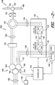
FIG. 1 depicts an exemplary doubly-fed induction generator (DFIG)wind turbine system 100 according to an exemplary embodiment of the present disclosure. - In the
exemplary system 100, arotor 106 includes a plurality ofrotor blades 108 coupled to a rotatinghub 110, and together define a propeller. The propeller is coupled to anoptional gear box 112, which is, in turn, coupled to agenerator 120. In accordance with aspects of the present disclosure, thegenerator 120 is a doubly fed induction generator (DFIG) 120. -
DFIG 120 is typically coupled to astator bus 122 and apower converter 130 via arotor bus 124. Thestator bus 122 provides an output multiphase power (e.g. three-phase power) from a stator ofDFIG 120 and therotor bus 124 provides an output multiphase power (e.g. three-phase power) of the rotor ofDFIG 120. Referring to thepower converter 130,DFIG 120 is coupled via therotor bus 124 to arotor side converter 132. Therotor side converter 132 is coupled to aline side converter 134 which in turn is coupled to aline side bus 138. - In exemplary configurations, the
rotor side converter 132 and theline side converter 134 are configured for normal operating mode in a three-phase, pulse width modulation (PWM) arrangement using insulated gate bipolar transistors (IGBTs) as switching devices. Other suitable switching devices can be used, such as insulated gate commuted thyristors, MOSFETs, bipolar transistors, silicon controlled rectifiers, or other suitable switching devices. Therotor side converter 132 and theline side converter 134 can be coupled via aDC link 135 across which is theDC link capacitor 136. - The
power converter 130 can be coupled to acontroller 140 to control the operation of therotor side converter 132 and theline side converter 134. For instance, thecontroller 140 can send control commands to therotor side converter 132 andline side converter 134 to control the modulation of switching elements (such as IGBTs) used in thepower converter 130 to provide a desired real and reactive power output. Thecontroller 140 can be any suitable control circuit. For instance, in one aspect the controller can include summers, compensating regulators, and other devices used to process signals received at thecontroller 140. In another embodiment, thecontroller 140 can include a processing device (e.g. microprocessor, microcontroller, etc.) executing computer-readable instructions stored in a computer-readable medium. The instructions when executed by the processing device can cause the processing device to perform control operations, such as regulating voltage of the DFIGwind turbine system 100 according to any exemplary aspects of the present disclosure. - As illustrated, the
system 100 includes atransformer 160 coupling thewind turbine system 100 to anelectrical grid 180. Thetransformer 160 ofFIG. 1 is a three-winding transformer that includes a high voltage (e.g. greater than 12 KVAC) primary winding 162 coupled to the electrical grid, a medium voltage (e.g. 6 KVAC) secondary winding 164 coupled to thestator bus 122, and a low voltage (e.g. 575 VAC, 690 VAC, etc.) auxiliary winding 166 coupled to theline bus 138. - An
auxiliary power feed 170 is coupled to the output of thepower converter 130. Theauxiliary power feed 170 acts as a power source for various components of thewind turbine system 100. For instance, theauxiliary power feed 170 can power fans, pumps, motors, and other suitable components of thewind turbine system 100. - In operation, power generated at
DFIG 120 by rotating therotor 106 is provided via a dual path toelectrical grid 180. The dual paths are defined by thestator bus 122 and therotor bus 124. On therotor bus side 124, sinusoidal multi-phase (e.g. three-phase) alternating current (AC) power is provided to thepower converter 130. The rotorside power converter 132 converts the AC power provided from therotor bus 124 into direct current (DC) power and provides the DC power to theDC link 135. Switching devices (e.g. IGBTs) used in parallel bridge circuits of the rotorside power converter 132 can be modulated to convert the AC power provided from therotor bus 124 into DC power suitable for theDC link 135. - The
line side converter 134 converts the DC power on the DC link 135 into AC power at a frequency suitable for theelectrical grid 180. In particular, switching devices (e.g. IGBTs) used in bridge circuits of the lineside power converter 134 can be modulated to convert the DC power on the DC link 135 into AC power on theline side bus 138. The power from thepower converter 130 can be provided via the auxiliary winding 166 of thetransformer 160 to theelectrical grid 180. - Various circuit breakers, fuses, switches, contactors, and other devices, such as
grid breaker 158,stator bus breaker 156,stator sync switch 154, andline bus breaker 152, can be included in thesystem 100 to connect or disconnect corresponding buses, for example, when current flow is excessive and can damage components of thewind turbine system 100 or for other operational considerations. Additional protection components can also be included in thewind turbine system 100. - The
power converter 130 can receive control signals from, for instance, thecontrol system 142 via thecontroller 140. The control signals can be based, among other things, on sensed conditions or operating characteristics of thewind turbine system 100. For instance, the control signals can be based on sensed voltage associated with thetransformer 160 as determined by avoltage sensor 144. As another example, the control signals can be based on sensed voltage associated with theauxiliary power feed 170 as determined by avoltage sensor 146. - Typically, the control signals provide for control of the operation of the
power converter 130. For example, feedback in the form of sensed speed of theDFIG 120 can be used to control the conversion of the output power from therotor bus 124 to maintain a proper and balanced multi-phase (e.g. three-phase) power supply. Other feedback from other sensors can also be used by thecontrol system 142 to control thepower converter 130, including, for example, stator and rotor bus voltages and current feedbacks. Using the various forms of feedback information, switching control signals (e.g. gate timing commands for IGBTs), stator synchronizing control signals, and circuit breaker signals can be generated. - According to various aspects of the present disclosure, the voltage of the
auxiliary power feed 170 can be regulated by thecontroller 140. In particular, thecontroller 140 can control thepower converter 130 to output excess reactive power to a reactive element coupled between thepower converter 130 and thestator bus 122 to regulate the voltage of theauxiliary power feed 170. Outputting the reactive power to the reactive element will influence the voltage of theline bus 138 and correspondingly the voltage at theauxiliary power feed 170. As a result, theauxiliary power feed 170 can be regulated to operate within a narrower operating range when compared to the operating range of thewind turbine system 100. - In the embodiment shown in
FIG. 1 , thecontroller 140 can monitor a voltage associated with thetransformer 160 usingvoltage sensor 144. The voltage associated with thetransformer 160 can be the voltage of the primary winding 162 or the voltage of a secondary winding, such as the voltage of secondary winding 164 or auxiliary winding 166. Based on the voltage associated with thetransformer 160, thecontroller 140 can identify a reactive power output for thepower converter 130 to maintain the voltage of the auxiliary power feed 130 to be within a predefined tolerance of nominal voltage for theauxiliary power feed 170, such as within 10% of the nominal voltage of theauxiliary power feed 170. Thecontroller 140 can then send control commands to thepower converter 130, such as gate timing commands for IGBTs used in theline side converter 134 and/or therotor side converter 132, to control thepower converter 130 to output the identified reactive power from thepower converter 130 to a reactive element coupled between theauxiliary power feed 170 and thestator bus 122. - In the embodiment shown in
FIG. 1 , the reactive element is the auxiliary winding 166 of thetransformer 160. More particularly, the impedance of the auxiliary winding 166 of thetransformer 160 can be sufficient to allow regulation of theauxiliary power feed 130 by outputting reactive power to the auxiliary winding 166 of the transformer. - The excess reactive power supplied to the auxiliary winding 166 will influence the voltage of the
auxiliary power feed 170 such that the operating range of theauxiliary power feed 170 can be maintained within a predetermined tolerance of nominal voltage. For instance, theauxiliary power feed 170 can be maintained within an operating range of nominal voltage ±10%, while the voltage on the primary winding 162 of thetransformer 160 can be maintained within an operating range of nominal voltage ±15%. - In a particular implementation, the
controller 140 can be configured to monitor the voltage of the auxiliary power feed 170 to determine whether the auxiliary winding remains within the predetermined tolerance of nominal voltage. For instance, thecontroller 140 can monitor the voltage associated with theauxiliary power feed 170 usingvoltage sensor 146. If the voltage exceeds or falls below a certain threshold, such as within 10% of nominal voltage for the auxiliary power feed, thecontroller 140 can control thepower converter 130 to adjust the reactive power output of thepower converter 130 until the voltage of theauxiliary power feed 170 is maintained within the predetermined tolerance. - In this manner, the
controller 140 can regulate the voltage of the auxiliary power feed 170 to be within a predefined operating range while allowing the wind turbine system100 to have an increased operating range output. As a result, standard components can be used in the auxiliary power system of thewind turbine system 100, leading to lower cost, shorter design/development/test schedule, and reduced engineering effort. -
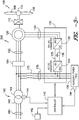
FIG. 2 depicts a DFIGwind turbine system 200 according to another exemplary embodiment of the present disclosure. The DFIGwind turbine system 200 is substantially similar to thewind turbine system 100 ofFIG. 1 , except that the DFIGwind turbine system 200 ofFIG. 2 includes an additional reactive element, namely aninductive element 172, coupled between the output of thepower converter 130 and the auxiliary winding 166. Certain circuit breakers, switches, contacts, and other devices are not illustrated inFIG. 2 for purposes of clarity of illustration. - Similar to the
system 100 depicted inFIG. 1 , thecontroller 140 can regulate the voltage of theauxiliary power feed 170 by controlling thepower converter 130 to output reactive power to a reactive element coupled between theauxiliary power feed 170 and thestator bus 122. In the embodiment ofFIG. 2 , the reactive element includes the auxiliary winding 166 of thetransformer 160 as well as the additionalinductive element 172 coupled between theauxiliary power feed 170 and the auxiliary winding 166. Theinductive element 172 can be external to or a part of thepower converter 130. - The
inductive element 172 can provide any additional impedance necessary for regulating theauxiliary power feed 170 by outputting reactive power from thepower converter 130. For instance, if the impedance of the auxiliary winding 166 of thetransformer 160 is not sufficient to allow for regulation of theauxiliary power feed 170 by outputting reactive power from thepower converter 130, the additionalinductive element 172 can be included between theauxiliary power feed 170 and the auxiliary winding 166 of the transformer to provide the required additional impedance. -
FIG. 3 depicts a DFIGwind turbine system 300 according to yet another exemplary embodiment of the present disclosure. The DFIGwind turbine system 300 ofFIG. 3 is similar to the DFIGwind turbine system 100 ofFIG. 1 , except that the DFIGwind turbine system 300 includes a two-windingtransformer 190 coupling thewind turbine system 300 to anelectrical grid 180. The two-windingtransformer 190 includes a primary winding 192 coupled to theelectrical grid 180 and a secondary winding 194 coupled to thestator bus 122 and to theline bus 138. - Similar to the
system 100 depicted inFIG. 1 , thecontroller 140 can regulate the voltage of theauxiliary power feed 170 by controlling thepower converter 130 to output reactive power to a reactive element coupled between theauxiliary power feed 170 and thestator bus 122. In thesystem 300 ofFIG. 3 , the reactive element includes aninductive element 172 coupled between theauxiliary power feed 170 andstator bus 122. Theinductive element 172 can be external to or a part of thepower converter 130. Theinductive element 172 can provide the required impedance necessary for regulating theauxiliary power feed 170 by outputting reactive power from thepower converter 130. -
FIG. 4 depicts a flow diagram of an exemplary method (400) for regulating the auxiliary power feed of a DFIG wind turbine system. The method (400) will be discussed with reference to the exemplary DFIGwind turbine system 100 ofFIG. 1 . However, the method (400) can be implemented using any suitable system. In addition, althoughFIG. 4 depicts steps performed in a particular order for purposes of illustration and discussion, the methods discussed herein are not limited to any particular order or arrangement. One skilled in the art, using the disclosures provided herein, will appreciate that various steps of the methods can be omitted, rearranged, combined and/or adapted in various ways. - At (402), the method includes monitoring a voltage associated with a transformer coupling the DFIG system to the utility grid. For instance, the method can include monitoring, with
voltage sensor 144, the voltage oftransformer 160. The voltage associated with thetransformer 160 can be a voltage associated with the primary winding 162, secondary winding 164, and/or auxiliary winding 166 of thetransformer 160. Thesensor 144 can provide a signal indicative of the voltage associated with the transformer to thecontroller 140. - At (404), the method includes identifying a reactive power output for the power converter based on the voltage associated with the transformer. For instance, the
controller 140 can process the signal indicative of the voltage associated with the transformer received from thesensor 144 to identify a necessary reactive power output for thepower converter 130 to maintain the voltage of theauxiliary power feed 170 within a predefined threshold of nominal voltage, such as within ±10% of nominal voltage of theauxiliary power feed 170. The reactive power output can be identified using any suitable process or technique, such as by accessing a model defining the relationships between one or more components of the DFIG system. - Once the reactive power output has been identified, a power converter can be controlled to output the identified reactive power to at least one reactive element to regulate the voltage of the auxiliary power feed (406). For instance, the
controller 140 can send control commands to thepower converter 130 to control thepower converter 130 to output the identified reactive power to the reactive element. In one aspect, the control commands can control the modulation of switching devices (IGBTs) used in thepower converter 130 such that thepower converter 130 provides the identified reactive power to the reactive element. - To ensure that the auxiliary power feed of the DFIG system remains within a predetermined tolerance (e.g. within 10% of nominal voltage), the method can further include monitoring the voltage of the auxiliary power feed to determine if the auxiliary power is maintained within the predetermine tolerance (408). For instance, the
voltage sensor 146 can monitor the voltage of theauxiliary power feed 170 and provide a signal indicative of the voltage to thecontroller 140. Thecontroller 140 can determine whether the voltage is within the predetermined tolerance based on the signal received from thevoltage sensor 146. - If the voltage of the auxiliary power feed is within the predetermined tolerance, the method can include maintaining the reactive power output of the power converter (410). For instance, the
controller 140 can send control commands to thepower converter 130 to maintain the reactive power output of thepower converter 130. Otherwise, the method can adjust the reactive power output of the power converter until the voltage of the auxiliary power feed is within the predetermined tolerance (412). For instance thecontroller 140 can send control commands to the power converter to adjust the reactive power output of thepower converter 130 until the voltage of theauxiliary power feed 170 is within the predetermined tolerance. The method can then return to (402) where the voltage of the auxiliary power feed continues to be regulated by monitoring the voltage associated with the transformer and outputting a reactive power from the power converter identified based on the voltage associated with the transformer.
Claims (18)
- A wind turbine system (100), comprising:a wind driven doubly fed induction generator (200) having a rotor and a stator, the stator providing AC power to a stator bus (122),a power converter (130) coupled to the rotor of said doubly fed induction generator (200), said power converter (130) providing an output to a line bus (138);a transformer (190) coupled to the stator bus (122);an auxiliary power feed (170) coupled to the at least one power converter (130);at least one reactive element (172) coupled between the auxiliary power feed (170) and the stator bus (122); anda control system (140,142) configured to control said power converter (130), said control system (140,142) being configured to regulate the voltage of said auxiliary power feed (170) by outputting reactive power from the power converter (130) to the-at least one reactive element (172)
characterized in that
the voltage of the auxiliary power feed (170) is regulated to operate within a narrower operating range when compared to the operating range of the wind turbine system. - The wind turbine system (100) of claim 1, wherein the transformer (190) comprises a primary winding (192) coupled to an electrical grid (180) and a secondary winding (194) coupled to the stator bus (122).
- The wind turbine system (100) of any preceding claim, wherein the at least one reactive element (172) comprises an inductive element coupled between the output of the power converter (130) and the stator bus (122).
- The wind turbine system (100) of any preceding claim, wherein the transformer (190) comprises a primary winding (192) coupled to an electrical grid, a secondary winding (194) coupled to the stator bus, and an auxiliary winding (166) coupled to the line bus.
- The wind turbine system (100) of claim 4, wherein the at least one reactive element (172) comprises the auxiliary winding (166).
- The wind turbine system (100) of claim 4 or claim 5, wherein the at least one reactive element (172) further comprises an inductive element coupled between the output of said power converter (130) and the auxiliary winding (166).
- The wind turbine system (100) of any preceding claim, wherein the system further comprises one or more fuses, circuit breakers (152, 154, 156), or contactors coupled between the output of the power converter (130) and the transformer (190).
- The wind turbine system (100) of any preceding claim, wherein said control system (140,142) is configured to adjust an output reactive power of said power converter (130) based on a voltage associated with the transformer to regulate the voltage of said auxiliary power feed.
- The wind turbine system (100) of claim 8, wherein the voltage associated with said transformer (190) is a voltage associated with a primary winding (192) of the transformer, the primary winding coupled to an electrical grid.
- The wind turbine system (100) of claim 8 or claim 9, wherein the voltage associated with said transformer (190) is a voltage associated with a secondary winding (194) of the transformer, the secondary winding coupled to the stator bus.
- The wind turbine system (100) of any preceding claim, wherein said control system (140,142) is configured to adjust the output reactive power of said power converter (130) to maintain the voltage of the auxiliary power feed (170) to be within about ± 10% of the nominal voltage of the auxiliary power feed (170).
- The wind turbine system (100) of any preceding claim, wherein a primary winding (162,192) of the transformer (160,190) has a wider operating range.
- The wind turbine system (100) of claim 12, wherein the wider operating range is nominal voltage ±: 15%.
- A method for regulating an auxiliary power feed (170) of a wind turbine system (100), the wind turbine system (100) comprising a wind driven doubly fed induction generator (200) having a rotor and a stator, the stator providing AC power to a stator bus (122), the wind turbine system further comprising a power converter (130) coupled to the rotor of the doubly fed induction generator (200), the power converter (130) providing an output to a line bus (138), the auxiliary power feed (170) coupled to the output of the power converter (130), the method comprising:monitoring a voltage associated with a transformer (190) coupling the wind turbine system (200) to an electrical grid (180);identifying a reactive power output for the power converter (130) based on the voltage associated with the transformer (190), the reactive power output identified to regulate the voltage of the auxiliary power feed (170); andcontrolling the power converter (130) to provide the identified reactive power output to the line bus (138) so as to regulate the voltage of the auxiliary power feed (170) to operate within a narrower range when compared to the operating range of the wind turbine system.
- The method of claim 14, wherein the identified reactive power output is provided to at least one reactive element (172) coupled between the auxiliary power source and the stator bus (122).
- The method of claim 14 or claim 15, wherein the reactive power output is identified to maintain the voltage of the auxiliary power feed (170) to be within about ± 10% of the nominal voltage of the auxiliary power feed (170).
- The method of any of claims 14 to 16, wherein the voltage associated with said transformer (190) is a voltage associated with a primary winding (192) of the transformer, the primary winding (192) being coupled to an electrical grid (180).
- The method of any of claims 14 to 17, comprising operating a primary winding (162,192) of the transformer (160,190) over a wider operating range.
Applications Claiming Priority (1)
| Application Number | Priority Date | Filing Date | Title |
|---|---|---|---|
| US13/613,410 US8669669B1 (en) | 2012-09-13 | 2012-09-13 | Voltage control in a doubly-fed induction generator wind turbine system |
Publications (3)
| Publication Number | Publication Date |
|---|---|
| EP2709266A2 EP2709266A2 (en) | 2014-03-19 |
| EP2709266A3 EP2709266A3 (en) | 2017-08-30 |
| EP2709266B1 true EP2709266B1 (en) | 2021-04-07 |
Family
ID=49150795
Family Applications (1)
| Application Number | Title | Priority Date | Filing Date |
|---|---|---|---|
| EP13183604.1A Active EP2709266B1 (en) | 2012-09-13 | 2013-09-09 | Voltage control in a doubly-fed induction generator wind turbine system |
Country Status (5)
| Country | Link |
|---|---|
| US (1) | US8669669B1 (en) |
| EP (1) | EP2709266B1 (en) |
| CA (1) | CA2826437C (en) |
| DK (1) | DK2709266T3 (en) |
| ES (1) | ES2879283T3 (en) |
Families Citing this family (23)
| Publication number | Priority date | Publication date | Assignee | Title |
|---|---|---|---|---|
| US8791671B2 (en) * | 2012-12-07 | 2014-07-29 | General Electric Company | System and method for optimization of dual bridge doubly fed induction generator (DFIG) |
| CN104113077B (en) * | 2014-06-30 | 2016-01-20 | 浙江大学 | A kind of control method for coordinating of dual-feed asynchronous wind power generator high voltage crossing |
| WO2016155739A1 (en) | 2015-04-01 | 2016-10-06 | Vestas Wind Systems A/S | Method for handling an over voltage ride through event |
| CN104779857A (en) * | 2015-04-13 | 2015-07-15 | 安徽理工大学 | Doubly-fed wind power generator control system based on matrix converter |
| US10107260B2 (en) * | 2015-11-19 | 2018-10-23 | General Electric Company | Wind turbine auxiliary circuit control |
| US10439533B2 (en) | 2017-01-05 | 2019-10-08 | General Electric Company | Power converter for doubly fed induction generator wind turbine systems |
| US10103663B1 (en) * | 2017-04-18 | 2018-10-16 | General Electric Company | Control method for protecting switching devices in power converters in doubly fed induction generator power systems |
| US10396695B2 (en) | 2017-04-18 | 2019-08-27 | General Electric Company | Method for protecting an electrical power system |
| US11081891B2 (en) | 2017-05-05 | 2021-08-03 | General Electric Company | Electrical power systems having reactive power and harmonic support components |
| CN108808725B (en) | 2017-05-05 | 2023-03-21 | 通用电气公司 | System and method for reactive power control of wind farm |
| US10784685B2 (en) | 2017-05-08 | 2020-09-22 | General Electric Company | Electrical power systems and subsystems |
| US10784689B2 (en) | 2017-05-08 | 2020-09-22 | General Electric Company | Electrical power systems and methods using distortion filters |
| US10587121B2 (en) * | 2017-05-23 | 2020-03-10 | General Electric Company | Electrical power systems and subsystems |
| US10491038B2 (en) * | 2017-06-15 | 2019-11-26 | General Electric Company | Electrical power subsystems and methods for controlling same |
| US10756658B2 (en) | 2017-07-06 | 2020-08-25 | General Electric Company | Allocating reactive power production for doubly fed induction generator wind turbine system |
| CN111316521B (en) * | 2017-09-15 | 2023-06-20 | 通用电气公司 | System and method for controlling an electric power system connected to an electric power grid |
| US10763674B2 (en) | 2017-09-29 | 2020-09-01 | General Electric Company | System and method for controlling cluster-based wind farms |
| WO2019094179A1 (en) * | 2017-11-13 | 2019-05-16 | General Electric Company | A power generation system having a direct current link connected to a ground terminal |
| WO2019177748A1 (en) * | 2018-03-12 | 2019-09-19 | General Electric Company | A power generation system and a method for operating the same |
| US11509141B2 (en) | 2018-07-10 | 2022-11-22 | Vestas Wind Sysiems A/S | Wind turbine power consumption control |
| US10826297B2 (en) * | 2018-11-06 | 2020-11-03 | General Electric Company | System and method for wind power generation and transmission in electrical power systems |
| US20230223751A1 (en) * | 2019-09-09 | 2023-07-13 | Elexsys Ip Pty Ltd | Two-Way Electrical Power Distribution Network |
| CN110571873B (en) * | 2019-10-16 | 2022-10-28 | 燕山大学 | Reactive compensation and vector control method for double-fed wind turbine generator |
Family Cites Families (13)
| Publication number | Priority date | Publication date | Assignee | Title |
|---|---|---|---|---|
| WO2001091279A1 (en) * | 2000-05-23 | 2001-11-29 | Vestas Wind Systems A/S | Variable speed wind turbine having a matrix converter |
| US7015595B2 (en) * | 2002-02-11 | 2006-03-21 | Vestas Wind Systems A/S | Variable speed wind turbine having a passive grid side rectifier with scalar power control and dependent pitch control |
| US7411309B2 (en) * | 2003-05-02 | 2008-08-12 | Xantrex Technology Inc. | Control system for doubly fed induction generator |
| ATE377286T1 (en) * | 2003-07-15 | 2007-11-15 | Gamesa Innovation & Tech Sl | CONTROL AND PROTECTION DEVICE FOR A DOUBLE FEEDED INDUCTION GENERATOR SYSTEM |
| US6924565B2 (en) * | 2003-08-18 | 2005-08-02 | General Electric Company | Continuous reactive power support for wind turbine generators |
| JP4269941B2 (en) | 2004-01-08 | 2009-05-27 | 株式会社日立製作所 | Wind power generator and control method thereof |
| DE102004013131A1 (en) * | 2004-03-17 | 2005-10-06 | Siemens Ag | Wind turbine |
| US7391126B2 (en) * | 2006-06-30 | 2008-06-24 | General Electric Company | Systems and methods for an integrated electrical sub-system powered by wind energy |
| CN102132486B (en) * | 2009-02-20 | 2014-07-02 | 三菱重工业株式会社 | Wind power generating apparatus |
| EP2464860B1 (en) * | 2009-08-14 | 2015-04-22 | Vestas Wind Systems A/S | A variable speed wind turbine, and a method for operating the variable speed wind turbine during a power imbalance event |
| ES2586334T3 (en) * | 2009-08-21 | 2016-10-13 | Vestas Wind Systems A/S | System and method to monitor power filters and detect a power filter failure in a wind turbine electric generator |
| US9077205B2 (en) * | 2012-03-05 | 2015-07-07 | General Electric Company | Auxiliary equipment system and method of operating the same |
| US9416773B2 (en) * | 2012-04-04 | 2016-08-16 | Gamesa Innovation & Technology, S.L. | Power generation and distribution system for a wind turbine |
-
2012
- 2012-09-13 US US13/613,410 patent/US8669669B1/en active Active
-
2013
- 2013-09-05 CA CA2826437A patent/CA2826437C/en active Active
- 2013-09-09 DK DK13183604.1T patent/DK2709266T3/en active
- 2013-09-09 ES ES13183604T patent/ES2879283T3/en active Active
- 2013-09-09 EP EP13183604.1A patent/EP2709266B1/en active Active
Non-Patent Citations (1)
| Title |
|---|
| None * |
Also Published As
| Publication number | Publication date |
|---|---|
| ES2879283T3 (en) | 2021-11-22 |
| EP2709266A2 (en) | 2014-03-19 |
| CA2826437C (en) | 2016-01-05 |
| DK2709266T3 (en) | 2021-07-05 |
| US8669669B1 (en) | 2014-03-11 |
| CA2826437A1 (en) | 2014-03-13 |
| EP2709266A3 (en) | 2017-08-30 |
| US20140070536A1 (en) | 2014-03-13 |
Similar Documents
| Publication | Publication Date | Title |
|---|---|---|
| EP2709266B1 (en) | Voltage control in a doubly-fed induction generator wind turbine system | |
| US9617976B2 (en) | Systems and methods for increasing wind turbine power output | |
| EP2448079B1 (en) | Method and System for Providing Increased Turbine Output for Doubly Fed Induction Generator | |
| EP2811157B1 (en) | Methods for operating wind turbine system having dynamic brake | |
| US9018783B2 (en) | Doubly-fed induction generator wind turbine system having solid-state stator switch | |
| US10107260B2 (en) | Wind turbine auxiliary circuit control | |
| US9281761B2 (en) | Control scheme for current balancing between parallel bridge circuits | |
| US8853876B1 (en) | Switching-based control for a power converter | |
| US9343991B2 (en) | Current balance control for non-interleaved parallel bridge circuits in power converter | |
| EP3731405A1 (en) | System and method for reactive power control of a wind turbine by varying switching frequency of rotor side converter | |
| US10581247B1 (en) | System and method for reactive power control of wind turbines in a wind farm supported with auxiliary reactive power compensation | |
| US20200158085A1 (en) | Power converter for full conversion wind turbine systems | |
| EP2725701B1 (en) | Current balance control in converter for doubly fed induction generator wind turbine system | |
| US10439533B2 (en) | Power converter for doubly fed induction generator wind turbine systems | |
| US10063172B2 (en) | Controlled braking of a generator | |
| US10958200B1 (en) | System and method for operating a wind turbine power system during low wind speeds to improve efficiency | |
| US11196260B2 (en) | System and method for control of reactive power from a reactive power compensation device in a wind turbine system | |
| US8791671B2 (en) | System and method for optimization of dual bridge doubly fed induction generator (DFIG) |
Legal Events
| Date | Code | Title | Description |
|---|---|---|---|
| PUAI | Public reference made under article 153(3) epc to a published international application that has entered the european phase |
Free format text: ORIGINAL CODE: 0009012 |
|
| AK | Designated contracting states |
Kind code of ref document: A2 Designated state(s): AL AT BE BG CH CY CZ DE DK EE ES FI FR GB GR HR HU IE IS IT LI LT LU LV MC MK MT NL NO PL PT RO RS SE SI SK SM TR |
|
| AX | Request for extension of the european patent |
Extension state: BA ME |
|
| PUAL | Search report despatched |
Free format text: ORIGINAL CODE: 0009013 |
|
| AK | Designated contracting states |
Kind code of ref document: A3 Designated state(s): AL AT BE BG CH CY CZ DE DK EE ES FI FR GB GR HR HU IE IS IT LI LT LU LV MC MK MT NL NO PL PT RO RS SE SI SK SM TR |
|
| AX | Request for extension of the european patent |
Extension state: BA ME |
|
| RIC1 | Information provided on ipc code assigned before grant |
Ipc: H02P 9/00 20060101AFI20170726BHEP |
|
| STAA | Information on the status of an ep patent application or granted ep patent |
Free format text: STATUS: REQUEST FOR EXAMINATION WAS MADE |
|
| 17P | Request for examination filed |
Effective date: 20180228 |
|
| RBV | Designated contracting states (corrected) |
Designated state(s): AL AT BE BG CH CY CZ DE DK EE ES FI FR GB GR HR HU IE IS IT LI LT LU LV MC MK MT NL NO PL PT RO RS SE SI SK SM TR |
|
| GRAP | Despatch of communication of intention to grant a patent |
Free format text: ORIGINAL CODE: EPIDOSNIGR1 |
|
| STAA | Information on the status of an ep patent application or granted ep patent |
Free format text: STATUS: GRANT OF PATENT IS INTENDED |
|
| RIC1 | Information provided on ipc code assigned before grant |
Ipc: H02P 9/00 20060101AFI20200429BHEP |
|
| INTG | Intention to grant announced |
Effective date: 20200527 |
|
| GRAJ | Information related to disapproval of communication of intention to grant by the applicant or resumption of examination proceedings by the epo deleted |
Free format text: ORIGINAL CODE: EPIDOSDIGR1 |
|
| STAA | Information on the status of an ep patent application or granted ep patent |
Free format text: STATUS: REQUEST FOR EXAMINATION WAS MADE |
|
| GRAP | Despatch of communication of intention to grant a patent |
Free format text: ORIGINAL CODE: EPIDOSNIGR1 |
|
| STAA | Information on the status of an ep patent application or granted ep patent |
Free format text: STATUS: GRANT OF PATENT IS INTENDED |
|
| INTC | Intention to grant announced (deleted) | ||
| INTG | Intention to grant announced |
Effective date: 20201030 |
|
| GRAS | Grant fee paid |
Free format text: ORIGINAL CODE: EPIDOSNIGR3 |
|
| GRAA | (expected) grant |
Free format text: ORIGINAL CODE: 0009210 |
|
| STAA | Information on the status of an ep patent application or granted ep patent |
Free format text: STATUS: THE PATENT HAS BEEN GRANTED |
|
| AK | Designated contracting states |
Kind code of ref document: B1 Designated state(s): AL AT BE BG CH CY CZ DE DK EE ES FI FR GB GR HR HU IE IS IT LI LT LU LV MC MK MT NL NO PL PT RO RS SE SI SK SM TR |
|
| REG | Reference to a national code |
Ref country code: GB Ref legal event code: FG4D |
|
| REG | Reference to a national code |
Ref country code: AT Ref legal event code: REF Ref document number: 1380978 Country of ref document: AT Kind code of ref document: T Effective date: 20210415 Ref country code: CH Ref legal event code: EP |
|
| REG | Reference to a national code |
Ref country code: DE Ref legal event code: R096 Ref document number: 602013076704 Country of ref document: DE |
|
| REG | Reference to a national code |
Ref country code: IE Ref legal event code: FG4D |
|
| REG | Reference to a national code |
Ref country code: DK Ref legal event code: T3 Effective date: 20210701 |
|
| REG | Reference to a national code |
Ref country code: LT Ref legal event code: MG9D |
|
| REG | Reference to a national code |
Ref country code: NL Ref legal event code: MP Effective date: 20210407 Ref country code: AT Ref legal event code: MK05 Ref document number: 1380978 Country of ref document: AT Kind code of ref document: T Effective date: 20210407 |
|
| PG25 | Lapsed in a contracting state [announced via postgrant information from national office to epo] |
Ref country code: AT Free format text: LAPSE BECAUSE OF FAILURE TO SUBMIT A TRANSLATION OF THE DESCRIPTION OR TO PAY THE FEE WITHIN THE PRESCRIBED TIME-LIMIT Effective date: 20210407 Ref country code: BG Free format text: LAPSE BECAUSE OF FAILURE TO SUBMIT A TRANSLATION OF THE DESCRIPTION OR TO PAY THE FEE WITHIN THE PRESCRIBED TIME-LIMIT Effective date: 20210707 Ref country code: HR Free format text: LAPSE BECAUSE OF FAILURE TO SUBMIT A TRANSLATION OF THE DESCRIPTION OR TO PAY THE FEE WITHIN THE PRESCRIBED TIME-LIMIT Effective date: 20210407 Ref country code: NL Free format text: LAPSE BECAUSE OF FAILURE TO SUBMIT A TRANSLATION OF THE DESCRIPTION OR TO PAY THE FEE WITHIN THE PRESCRIBED TIME-LIMIT Effective date: 20210407 Ref country code: LT Free format text: LAPSE BECAUSE OF FAILURE TO SUBMIT A TRANSLATION OF THE DESCRIPTION OR TO PAY THE FEE WITHIN THE PRESCRIBED TIME-LIMIT Effective date: 20210407 Ref country code: FI Free format text: LAPSE BECAUSE OF FAILURE TO SUBMIT A TRANSLATION OF THE DESCRIPTION OR TO PAY THE FEE WITHIN THE PRESCRIBED TIME-LIMIT Effective date: 20210407 |
|
| REG | Reference to a national code |
Ref country code: ES Ref legal event code: FG2A Ref document number: 2879283 Country of ref document: ES Kind code of ref document: T3 Effective date: 20211122 |
|
| PG25 | Lapsed in a contracting state [announced via postgrant information from national office to epo] |
Ref country code: IS Free format text: LAPSE BECAUSE OF FAILURE TO SUBMIT A TRANSLATION OF THE DESCRIPTION OR TO PAY THE FEE WITHIN THE PRESCRIBED TIME-LIMIT Effective date: 20210807 Ref country code: LV Free format text: LAPSE BECAUSE OF FAILURE TO SUBMIT A TRANSLATION OF THE DESCRIPTION OR TO PAY THE FEE WITHIN THE PRESCRIBED TIME-LIMIT Effective date: 20210407 Ref country code: GR Free format text: LAPSE BECAUSE OF FAILURE TO SUBMIT A TRANSLATION OF THE DESCRIPTION OR TO PAY THE FEE WITHIN THE PRESCRIBED TIME-LIMIT Effective date: 20210708 Ref country code: RS Free format text: LAPSE BECAUSE OF FAILURE TO SUBMIT A TRANSLATION OF THE DESCRIPTION OR TO PAY THE FEE WITHIN THE PRESCRIBED TIME-LIMIT Effective date: 20210407 Ref country code: SE Free format text: LAPSE BECAUSE OF FAILURE TO SUBMIT A TRANSLATION OF THE DESCRIPTION OR TO PAY THE FEE WITHIN THE PRESCRIBED TIME-LIMIT Effective date: 20210407 Ref country code: PT Free format text: LAPSE BECAUSE OF FAILURE TO SUBMIT A TRANSLATION OF THE DESCRIPTION OR TO PAY THE FEE WITHIN THE PRESCRIBED TIME-LIMIT Effective date: 20210809 Ref country code: NO Free format text: LAPSE BECAUSE OF FAILURE TO SUBMIT A TRANSLATION OF THE DESCRIPTION OR TO PAY THE FEE WITHIN THE PRESCRIBED TIME-LIMIT Effective date: 20210707 Ref country code: PL Free format text: LAPSE BECAUSE OF FAILURE TO SUBMIT A TRANSLATION OF THE DESCRIPTION OR TO PAY THE FEE WITHIN THE PRESCRIBED TIME-LIMIT Effective date: 20210407 |
|
| REG | Reference to a national code |
Ref country code: DE Ref legal event code: R097 Ref document number: 602013076704 Country of ref document: DE |
|
| PG25 | Lapsed in a contracting state [announced via postgrant information from national office to epo] |
Ref country code: CZ Free format text: LAPSE BECAUSE OF FAILURE TO SUBMIT A TRANSLATION OF THE DESCRIPTION OR TO PAY THE FEE WITHIN THE PRESCRIBED TIME-LIMIT Effective date: 20210407 Ref country code: EE Free format text: LAPSE BECAUSE OF FAILURE TO SUBMIT A TRANSLATION OF THE DESCRIPTION OR TO PAY THE FEE WITHIN THE PRESCRIBED TIME-LIMIT Effective date: 20210407 Ref country code: SM Free format text: LAPSE BECAUSE OF FAILURE TO SUBMIT A TRANSLATION OF THE DESCRIPTION OR TO PAY THE FEE WITHIN THE PRESCRIBED TIME-LIMIT Effective date: 20210407 Ref country code: SK Free format text: LAPSE BECAUSE OF FAILURE TO SUBMIT A TRANSLATION OF THE DESCRIPTION OR TO PAY THE FEE WITHIN THE PRESCRIBED TIME-LIMIT Effective date: 20210407 Ref country code: RO Free format text: LAPSE BECAUSE OF FAILURE TO SUBMIT A TRANSLATION OF THE DESCRIPTION OR TO PAY THE FEE WITHIN THE PRESCRIBED TIME-LIMIT Effective date: 20210407 |
|
| PLBE | No opposition filed within time limit |
Free format text: ORIGINAL CODE: 0009261 |
|
| STAA | Information on the status of an ep patent application or granted ep patent |
Free format text: STATUS: NO OPPOSITION FILED WITHIN TIME LIMIT |
|
| 26N | No opposition filed |
Effective date: 20220110 |
|
| REG | Reference to a national code |
Ref country code: CH Ref legal event code: PL |
|
| REG | Reference to a national code |
Ref country code: BE Ref legal event code: MM Effective date: 20210930 |
|
| GBPC | Gb: european patent ceased through non-payment of renewal fee |
Effective date: 20210909 |
|
| PG25 | Lapsed in a contracting state [announced via postgrant information from national office to epo] |
Ref country code: IS Free format text: LAPSE BECAUSE OF FAILURE TO SUBMIT A TRANSLATION OF THE DESCRIPTION OR TO PAY THE FEE WITHIN THE PRESCRIBED TIME-LIMIT Effective date: 20210807 Ref country code: MC Free format text: LAPSE BECAUSE OF FAILURE TO SUBMIT A TRANSLATION OF THE DESCRIPTION OR TO PAY THE FEE WITHIN THE PRESCRIBED TIME-LIMIT Effective date: 20210407 Ref country code: AL Free format text: LAPSE BECAUSE OF FAILURE TO SUBMIT A TRANSLATION OF THE DESCRIPTION OR TO PAY THE FEE WITHIN THE PRESCRIBED TIME-LIMIT Effective date: 20210407 |
|
| PG25 | Lapsed in a contracting state [announced via postgrant information from national office to epo] |
Ref country code: LU Free format text: LAPSE BECAUSE OF NON-PAYMENT OF DUE FEES Effective date: 20210909 Ref country code: IT Free format text: LAPSE BECAUSE OF FAILURE TO SUBMIT A TRANSLATION OF THE DESCRIPTION OR TO PAY THE FEE WITHIN THE PRESCRIBED TIME-LIMIT Effective date: 20210407 Ref country code: IE Free format text: LAPSE BECAUSE OF NON-PAYMENT OF DUE FEES Effective date: 20210909 Ref country code: GB Free format text: LAPSE BECAUSE OF NON-PAYMENT OF DUE FEES Effective date: 20210909 Ref country code: FR Free format text: LAPSE BECAUSE OF NON-PAYMENT OF DUE FEES Effective date: 20210930 Ref country code: BE Free format text: LAPSE BECAUSE OF NON-PAYMENT OF DUE FEES Effective date: 20210930 |
|
| PG25 | Lapsed in a contracting state [announced via postgrant information from national office to epo] |
Ref country code: LI Free format text: LAPSE BECAUSE OF NON-PAYMENT OF DUE FEES Effective date: 20210930 Ref country code: CH Free format text: LAPSE BECAUSE OF NON-PAYMENT OF DUE FEES Effective date: 20210930 |
|
| PG25 | Lapsed in a contracting state [announced via postgrant information from national office to epo] |
Ref country code: HU Free format text: LAPSE BECAUSE OF FAILURE TO SUBMIT A TRANSLATION OF THE DESCRIPTION OR TO PAY THE FEE WITHIN THE PRESCRIBED TIME-LIMIT; INVALID AB INITIO Effective date: 20130909 |
|
| PG25 | Lapsed in a contracting state [announced via postgrant information from national office to epo] |
Ref country code: CY Free format text: LAPSE BECAUSE OF FAILURE TO SUBMIT A TRANSLATION OF THE DESCRIPTION OR TO PAY THE FEE WITHIN THE PRESCRIBED TIME-LIMIT Effective date: 20210407 |
|
| P01 | Opt-out of the competence of the unified patent court (upc) registered |
Effective date: 20230530 |
|
| PGFP | Annual fee paid to national office [announced via postgrant information from national office to epo] |
Ref country code: DK Payment date: 20230822 Year of fee payment: 11 Ref country code: DE Payment date: 20230822 Year of fee payment: 11 |
|
| REG | Reference to a national code |
Ref country code: DE Ref legal event code: R082 Ref document number: 602013076704 Country of ref document: DE Representative=s name: ZIMMERMANN & PARTNER PATENTANWAELTE MBB, DE Ref country code: DE Ref legal event code: R082 Ref document number: 602013076704 Country of ref document: DE Ref country code: DE Ref legal event code: R081 Ref document number: 602013076704 Country of ref document: DE Owner name: GENERAL ELECTRIC RENOVABLES ESPANA, S.L., ES Free format text: FORMER OWNER: GENERAL ELECTRIC COMPANY, SCHENECTADY, NY, US |
|
| PGFP | Annual fee paid to national office [announced via postgrant information from national office to epo] |
Ref country code: ES Payment date: 20231002 Year of fee payment: 11 |
|
| REG | Reference to a national code |
Ref country code: DE Ref legal event code: R082 Ref document number: 602013076704 Country of ref document: DE Representative=s name: ZIMMERMANN & PARTNER PATENTANWAELTE MBB, DE |