EP2709265A2 - Schrittmotor-Phasenfehlererkennung - Google Patents
Schrittmotor-Phasenfehlererkennung Download PDFInfo
- Publication number
- EP2709265A2 EP2709265A2 EP13176052.2A EP13176052A EP2709265A2 EP 2709265 A2 EP2709265 A2 EP 2709265A2 EP 13176052 A EP13176052 A EP 13176052A EP 2709265 A2 EP2709265 A2 EP 2709265A2
- Authority
- EP
- European Patent Office
- Prior art keywords
- stepper motor
- duty cycle
- controller
- pwm
- threshold
- Prior art date
- Legal status (The legal status is an assumption and is not a legal conclusion. Google has not performed a legal analysis and makes no representation as to the accuracy of the status listed.)
- Granted
Links
Images


Classifications
-
- H—ELECTRICITY
- H02—GENERATION; CONVERSION OR DISTRIBUTION OF ELECTRIC POWER
- H02P—CONTROL OR REGULATION OF ELECTRIC MOTORS, ELECTRIC GENERATORS OR DYNAMO-ELECTRIC CONVERTERS; CONTROLLING TRANSFORMERS, REACTORS OR CHOKE COILS
- H02P8/00—Arrangements for controlling dynamo-electric motors rotating step by step
- H02P8/36—Protection against faults, e.g. against overheating or step-out; Indicating faults
Definitions
- a motor is an important component of an aircraft (e.g., an airplane).
- a motor may fail.
- a motor may fail due to an open circuit or stall condition, which may result in an inability to move the motor.
- stepper motor One type of motor used in aircraft is a so called stepper motor.
- a stepper motor is controlled by an external control circuit, such as a microcontroller.
- an external control circuit such as a microcontroller.
- one electromagnet is given power, which makes the rotor magnetically attracted to the electromagnet's poles.
- the rotor rotates slightly to align with the poles of the next one, and from there the process is repeated. Each of those slight rotations is called a "step" and is made upon the issuance of a step command by the control circuit.
- Detection of a failed stepper motor is typically based on a position tracking function. Using position tracking results in a delay from a time of the failure until a time that the failure is detected. Moreover, the fault may go undetected until a reposition command (e.g. the next "step command") is provided.
- a reposition command e.g. the next "step command
- a system comprises a stepper motor, and a controller configured to: measure a parameter associated with a current of the stepper motor prior to commanding a step in connection with the stepper motor, command the step in connection with the stepper motor, measure the parameter subsequent to commanding the step, compare the measurements of the parameter, and determine whether a fault exists with respect to the stepper motor based on the comparison of the measurements.
- a method comprises measuring, by a controller, a parameter associated with a current of a stepper motor prior to commanding a step in connection with the stepper motor, commanding, by the controller, the step in connection with the stepper motor, measuring, by the controller, the parameter subsequent to commanding the step, comparing, by the controller, the measurements of the parameter, and determining, by the controller, whether a fault exists with respect to the stepper motor based on the comparison of the measurements.
- an apparatus comprises at least one processor, and memory having instructions stored thereon that, when executed by the at least one processor, cause the apparatus to: measure a duty cycle of a pulse width modulation (PWM) associated with a current of a stepper motor prior to commanding a step in connection with the stepper motor, command the step in connection with the stepper motor, measure the duty cycle of the PWM subsequent to commanding the step, compare the measurements of the duty cycle of the PWM, and determine whether a fault exists with respect to the stepper motor based on the comparison of the measurements.
- PWM pulse width modulation
- FIG. 1 illustrates an exemplary system in accordance with one or more embodiments of the disclosure
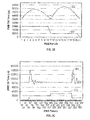
- FIGS. 2A-2C illustrate exemplary graphs in accordance with one or more embodiments of this disclosure.
- FIG. 3 illustrates an exemplary method in accordance with one or more embodiments of this disclosure.
- a fault associated with a motor may be detected.
- embodiments of the disclosure may monitor or control one or more currents, potentially in connection with a pulse width modulation (PWM) function.
- PWM pulse width modulation
- FIG. 1 illustrates an exemplary fault detection system 100.
- the system 100 may be associated with one or more applications or environments, such as an aircraft.
- the system 100 may include one or more motors, such as a motor 102.
- the motor 102 may be a stepper motor.
- the motor 102 may include one or more components or devices, such as one or more mechanical and/or electrical components known to those of skill in the art.
- the motor 102 may include one or more coils, such as coils 104.
- the system may include one or more power supplies, such as a power supply 106.
- the motor 102 may be powered by the power supply 106.
- the system 100 may include a controller 108.
- the controller 108 may include any combination of hardware, software, and/or firmware.
- the controller 108 may include one or more processors 110, and memory 112 having instructions stored thereon that, when executed by the one or more processors 110, cause the controller 108 to perform one or more methodological acts, such as those described herein.
- the controller 108 may be coupled to the motor 102 as shown in FIG. 1 .
- the controller 108 may be configured to control a current associated with the motor 102.
- the controller 108 may control the current of a stepper motor based on a pulse width modulation (PWM) function.
- PWM pulse width modulation
- an electromagnet or coil 104 may be selectively energized or de-energized to facilitate a step in the motor 102.
- a first of the coils 104 might need to de-energize before a second of the coils 104 can be driven or energized. While de-energizing, a current might not flow through a monitor point 116.
- the monitor point 116 may correspond to a node associated with, or coupled to, one or more of the coils 104 as shown in FIG. 1 . The absence of the current through the monitor point 116 may cause the PWM function to react by increasing a duty cycle. In the event that a coil 104 fails or sustains a fault, there may be no de-energizing period, and accordingly, no increase in the PWM duty cycle. As such, the duty cycle of the PWM function may be monitored to determine whether a fault exists with respect to the motor 102.
- the system 100 is illustrative. In some embodiments, one or more of the components or devices may be optional. In some embodiments, one or more additional devices not shown may be included. In some embodiments, the components or devices may be organized or arranged in a manner different from what is shown in FIG. 1 .
- FIGS. 2A-2C illustrate exemplary graphs in accordance with one or more aspects of this disclosure.
- Each of the graphs of FIG. 2A-2C may depict time counts on the vertical axis relative to sample numbers taken from a logic analyzer on the horizontal axis.
- the vertical axis may generally correspond to or include a PWM "on" time as measured in, e.g., microseconds ( ⁇ s) and may be proportional to a fixed PWM period.
- the horizontal axis may correspond to PWM periods.
- a cycle 202 may be composed of a number of steps. For example, transitions or steps may be included at approximately sample numbers forty-one (41), forty-nine (49), sixty-one (61), and sixty-nine (69). That same pattern of four transitions or steps may repeat itself starting at, e.g., approximately sample number eighty-one (81).
- FIG. 2A Also shown in FIG. 2A is a plot of the PWM "on" time 204.
- the PWM on time 204 may correspond to a time that a PWM function is active.
- the PWM on time 204 may be associated with the cycle 202.
- FIG. 2B is a graph of an individual step in the cycle 202. As shown in FIG. 2B , the downward step at sample number ten (10) in the cycle 202 may result in a (local) maxima in PWM on time 204 at approximately sample number sixteen (16). The delay between the commanded step and the maxima may be correlated to a loop time of the PWM function.
- FIG. 2C illustrates a graph that may be indicative of a fault, such as a broken coil (e.g., a coil 104).
- a fault such as a broken coil (e.g., a coil 104).
- a broken coil e.g., a coil 104
- FIG. 2C illustrates a graph that may be indicative of a fault, such as a broken coil (e.g., a coil 104).
- FIGS. 2A-2C are illustrative. In some embodiments, different counts, samples, or frequencies may be used.
- FIG. 3 illustrates a method in accordance with one or more embodiments of this disclosure.
- the method may execute in accordance with one or more systems, components, or devices, such as those described herein.
- the method of FIG. 3 may be used to detect whether a fault exists with a motor (e.g., the motor 102).
- the method may be implemented using hardware, software, firmware, or any combination thereof.
- the method may be implemented using a controller (e.g., the controller 108).
- a step in a motor may be commanded.
- the step may correspond to one of a number of steps associated with a full period of rotation of the motor.
- a duty cycle of a PWM function may be monitored.
- the duty cycle may be measured.
- the monitoring of block 304 may be triggered or initiated by the step commanded in block 302.
- a determination may be made whether the duty cycle of the PWM function changed in block 304 in an amount greater than a threshold, within a threshold amount of time (or samples). If so (e.g., the "Yes" path is taken out of block 306), then flow may proceed to block 302 to prepare for the next step or transition. Otherwise, flow may proceed from block 306 to block 308 (e.g., along the "No" path out of block 306), where a fault associated with the motor (e.g., a failed coil) may be declared.
- a fault associated with the motor e.g., a failed coil
- FIG. 3 The blocks or operations shown in FIG. 3 are illustrative. In some embodiments, some of the operations (or portions thereof) may be optional. In some embodiments, additional operations not shown may be included. In some embodiments, the operations may execute in an order or sequence different from what is shown.
- Embodiments of the disclosure may be used to detect a fault associated with a motor (e.g., a fault associated with a coil of the motor) within a number (e.g., four) steps. Aspects of the disclosure may allow for a faster detection of the fault relative to prior solutions. Such earlier/faster detection may be used to maintain dynamics of fuel flow. For example, in embodiments where multiple or redundant channels are available, a switch-over from a failed channel (e.g., a motor with a fault) to a healthy channel (e.g., a motor without a fault) may take place sooner.
- a failed channel e.g., a motor with a fault
- a healthy channel e.g., a motor without a fault
- various functions or acts may take place at a given location and/or in connection with the operation of one or more apparatuses or systems.
- a portion of a given function or act may be performed at a first device or location, and the remainder of the function or act may be performed at one or more additional devices or locations.
- aspects of the disclosure may be directed to one or more systems, apparatuses, and methods.
- executable instructions may be stored on one or more media, such as a non-transitory computer readable medium. The instructions, when executed, may cause an entity to perform one or more methodological acts.
- a device or entity such as a controller, may monitor a duty cycle of a PWM function to determine whether a motor (or coil associated with the motor) has sustained a fault.
Landscapes
- Engineering & Computer Science (AREA)
- Power Engineering (AREA)
- Control Of Stepping Motors (AREA)
- Control Of Electric Motors In General (AREA)
Applications Claiming Priority (1)
| Application Number | Priority Date | Filing Date | Title |
|---|---|---|---|
| US13/617,966 US8952646B2 (en) | 2012-09-14 | 2012-09-14 | Stepper motor phase failure detection |
Publications (3)
| Publication Number | Publication Date |
|---|---|
| EP2709265A2 true EP2709265A2 (de) | 2014-03-19 |
| EP2709265A3 EP2709265A3 (de) | 2017-03-22 |
| EP2709265B1 EP2709265B1 (de) | 2023-12-27 |
Family
ID=48748065
Family Applications (1)
| Application Number | Title | Priority Date | Filing Date |
|---|---|---|---|
| EP13176052.2A Active EP2709265B1 (de) | 2012-09-14 | 2013-07-11 | Schrittmotor-Phasenfehlererkennung |
Country Status (2)
| Country | Link |
|---|---|
| US (1) | US8952646B2 (de) |
| EP (1) | EP2709265B1 (de) |
Families Citing this family (1)
| Publication number | Priority date | Publication date | Assignee | Title |
|---|---|---|---|---|
| US20250183824A1 (en) * | 2023-11-30 | 2025-06-05 | Texas Instruments Incorporated | Methods and apparatus to sense changes in a load of a stepper motor |
Family Cites Families (5)
| Publication number | Priority date | Publication date | Assignee | Title |
|---|---|---|---|---|
| JPS56158978A (en) * | 1980-05-13 | 1981-12-08 | Citizen Watch Co Ltd | Electronic watch |
| DE9012436U1 (de) * | 1989-11-28 | 1992-01-02 | Siemens AG, 8000 München | Sicherheitssystem für einen Schrittmotorantrieb |
| US6047557A (en) * | 1995-06-07 | 2000-04-11 | Copeland Corporation | Adaptive control for a refrigeration system using pulse width modulated duty cycle scroll compressor |
| US5757596A (en) * | 1997-01-21 | 1998-05-26 | Ford Global Technologies, Inc. | Motor control assembly and method of controlling same |
| US8816614B2 (en) * | 2011-09-29 | 2014-08-26 | Infineon Technologies Ag | Diagnosis of over-current conditions in bipolar motor controllers |
-
2012
- 2012-09-14 US US13/617,966 patent/US8952646B2/en active Active
-
2013
- 2013-07-11 EP EP13176052.2A patent/EP2709265B1/de active Active
Non-Patent Citations (1)
| Title |
|---|
| None |
Also Published As
| Publication number | Publication date |
|---|---|
| US8952646B2 (en) | 2015-02-10 |
| EP2709265A3 (de) | 2017-03-22 |
| EP2709265B1 (de) | 2023-12-27 |
| US20140077748A1 (en) | 2014-03-20 |
Similar Documents
| Publication | Publication Date | Title |
|---|---|---|
| US9800191B2 (en) | Adaptive linear resonance actuator controller | |
| US8004226B2 (en) | Method and system for detecting a failed current sensor in a three-phase machine | |
| US10056851B2 (en) | System and method for induction motor speed estimation using a soft starter system | |
| US10935155B2 (en) | Electronic expansion valve, control system, and control method | |
| EP3224679B1 (de) | Erkennung von fehlern bei feldorientierten gesteuerten permanentmagnetsynchronmaschinen | |
| CN107270599B (zh) | 变频驱动器的控制与操作 | |
| US9983253B2 (en) | Method and apparatus for identifying the winding short of bar wound electric machine at standstill condition | |
| US20110260748A1 (en) | Apparatus and method for diagnosing permanent magnet demagnetization of permanent magnet synchronous motor, and apparatus for driving permanent magnet synchronous motor | |
| US9823309B2 (en) | Method for detecting an electrical fault in a generator assemblage, and means for implementation thereof | |
| EP2613163A1 (de) | Selbstdiagnosevorrichtung und Verfahren für eine elektrische Vorrichtung | |
| CN108603916B (zh) | 用于识别发电机单元中的故障的方法 | |
| WO2011037592A1 (en) | Sensorless lost/found rotor detection for permanent magnet motors | |
| JP2009038959A (ja) | 永久磁石同期電動機用の一つ以上の相の欠相検出方法 | |
| WO2017122309A1 (ja) | 電動機制御装置 | |
| CN111022307A (zh) | 压缩机的控制方法、压缩机控制器及空调机组 | |
| US9160263B2 (en) | System and method for monitoring and controlling a brushless electric motor | |
| BR102018068674A2 (pt) | Sistema e método de funcionamento sustentado durante queda de alimentação | |
| EP2709265B1 (de) | Schrittmotor-Phasenfehlererkennung | |
| US7411404B2 (en) | Apparatus, system, and method for detecting an electrical short condition in a dynamoelectric machine | |
| US11193978B2 (en) | Power conversion device, rotating machine system using same, and diagnosis method for same | |
| WO2023028504A1 (en) | Model based monitoring of faults in electro-hydraulic valves | |
| KR101348543B1 (ko) | 영구자석 모터의 권선 고장 판단 장치 및 그 방법 | |
| KR101689501B1 (ko) | 싸이리스터 스위치 고장 검지 장치를 구비한 다중 위상제어 정류기 및 고장 검지 방법 | |
| CN109256990A (zh) | 一种电机控制方法和装置 | |
| CN105227026B (zh) | 轴向通量永磁电机状态监测 |
Legal Events
| Date | Code | Title | Description |
|---|---|---|---|
| PUAI | Public reference made under article 153(3) epc to a published international application that has entered the european phase |
Free format text: ORIGINAL CODE: 0009012 |
|
| AK | Designated contracting states |
Kind code of ref document: A2 Designated state(s): AL AT BE BG CH CY CZ DE DK EE ES FI FR GB GR HR HU IE IS IT LI LT LU LV MC MK MT NL NO PL PT RO RS SE SI SK SM TR |
|
| AX | Request for extension of the european patent |
Extension state: BA ME |
|
| PUAL | Search report despatched |
Free format text: ORIGINAL CODE: 0009013 |
|
| AK | Designated contracting states |
Kind code of ref document: A3 Designated state(s): AL AT BE BG CH CY CZ DE DK EE ES FI FR GB GR HR HU IE IS IT LI LT LU LV MC MK MT NL NO PL PT RO RS SE SI SK SM TR |
|
| AX | Request for extension of the european patent |
Extension state: BA ME |
|
| RIC1 | Information provided on ipc code assigned before grant |
Ipc: H02P 8/36 20060101AFI20170210BHEP |
|
| STAA | Information on the status of an ep patent application or granted ep patent |
Free format text: STATUS: REQUEST FOR EXAMINATION WAS MADE |
|
| 17P | Request for examination filed |
Effective date: 20170921 |
|
| RBV | Designated contracting states (corrected) |
Designated state(s): AL AT BE BG CH CY CZ DE DK EE ES FI FR GB GR HR HU IE IS IT LI LT LU LV MC MK MT NL NO PL PT RO RS SE SI SK SM TR |
|
| STAA | Information on the status of an ep patent application or granted ep patent |
Free format text: STATUS: EXAMINATION IS IN PROGRESS |
|
| 17Q | First examination report despatched |
Effective date: 20200207 |
|
| GRAP | Despatch of communication of intention to grant a patent |
Free format text: ORIGINAL CODE: EPIDOSNIGR1 |
|
| STAA | Information on the status of an ep patent application or granted ep patent |
Free format text: STATUS: GRANT OF PATENT IS INTENDED |
|
| INTG | Intention to grant announced |
Effective date: 20230714 |
|
| RAP3 | Party data changed (applicant data changed or rights of an application transferred) |
Owner name: HAMILTON SUNDSTRAND CORPORATION |
|
| RAP3 | Party data changed (applicant data changed or rights of an application transferred) |
Owner name: HAMILTON SUNDSTRAND CORPORATION |
|
| GRAS | Grant fee paid |
Free format text: ORIGINAL CODE: EPIDOSNIGR3 |
|
| GRAA | (expected) grant |
Free format text: ORIGINAL CODE: 0009210 |
|
| STAA | Information on the status of an ep patent application or granted ep patent |
Free format text: STATUS: THE PATENT HAS BEEN GRANTED |
|
| AK | Designated contracting states |
Kind code of ref document: B1 Designated state(s): AL AT BE BG CH CY CZ DE DK EE ES FI FR GB GR HR HU IE IS IT LI LT LU LV MC MK MT NL NO PL PT RO RS SE SI SK SM TR |
|
| REG | Reference to a national code |
Ref country code: GB Ref legal event code: FG4D |
|
| REG | Reference to a national code |
Ref country code: CH Ref legal event code: EP |
|
| REG | Reference to a national code |
Ref country code: DE Ref legal event code: R096 Ref document number: 602013085109 Country of ref document: DE |
|
| REG | Reference to a national code |
Ref country code: IE Ref legal event code: FG4D |
|
| PG25 | Lapsed in a contracting state [announced via postgrant information from national office to epo] |
Ref country code: GR Free format text: LAPSE BECAUSE OF FAILURE TO SUBMIT A TRANSLATION OF THE DESCRIPTION OR TO PAY THE FEE WITHIN THE PRESCRIBED TIME-LIMIT Effective date: 20240328 |
|
| REG | Reference to a national code |
Ref country code: LT Ref legal event code: MG9D |
|
| PG25 | Lapsed in a contracting state [announced via postgrant information from national office to epo] |
Ref country code: LT Free format text: LAPSE BECAUSE OF FAILURE TO SUBMIT A TRANSLATION OF THE DESCRIPTION OR TO PAY THE FEE WITHIN THE PRESCRIBED TIME-LIMIT Effective date: 20231227 |
|
| PG25 | Lapsed in a contracting state [announced via postgrant information from national office to epo] |
Ref country code: ES Free format text: LAPSE BECAUSE OF FAILURE TO SUBMIT A TRANSLATION OF THE DESCRIPTION OR TO PAY THE FEE WITHIN THE PRESCRIBED TIME-LIMIT Effective date: 20231227 |
|
| PG25 | Lapsed in a contracting state [announced via postgrant information from national office to epo] |
Ref country code: LT Free format text: LAPSE BECAUSE OF FAILURE TO SUBMIT A TRANSLATION OF THE DESCRIPTION OR TO PAY THE FEE WITHIN THE PRESCRIBED TIME-LIMIT Effective date: 20231227 Ref country code: GR Free format text: LAPSE BECAUSE OF FAILURE TO SUBMIT A TRANSLATION OF THE DESCRIPTION OR TO PAY THE FEE WITHIN THE PRESCRIBED TIME-LIMIT Effective date: 20240328 Ref country code: FI Free format text: LAPSE BECAUSE OF FAILURE TO SUBMIT A TRANSLATION OF THE DESCRIPTION OR TO PAY THE FEE WITHIN THE PRESCRIBED TIME-LIMIT Effective date: 20231227 Ref country code: ES Free format text: LAPSE BECAUSE OF FAILURE TO SUBMIT A TRANSLATION OF THE DESCRIPTION OR TO PAY THE FEE WITHIN THE PRESCRIBED TIME-LIMIT Effective date: 20231227 Ref country code: BG Free format text: LAPSE BECAUSE OF FAILURE TO SUBMIT A TRANSLATION OF THE DESCRIPTION OR TO PAY THE FEE WITHIN THE PRESCRIBED TIME-LIMIT Effective date: 20240327 |
|
| REG | Reference to a national code |
Ref country code: NL Ref legal event code: MP Effective date: 20231227 |
|
| REG | Reference to a national code |
Ref country code: AT Ref legal event code: MK05 Ref document number: 1645470 Country of ref document: AT Kind code of ref document: T Effective date: 20231227 |
|
| PG25 | Lapsed in a contracting state [announced via postgrant information from national office to epo] |
Ref country code: NL Free format text: LAPSE BECAUSE OF FAILURE TO SUBMIT A TRANSLATION OF THE DESCRIPTION OR TO PAY THE FEE WITHIN THE PRESCRIBED TIME-LIMIT Effective date: 20231227 |
|
| PG25 | Lapsed in a contracting state [announced via postgrant information from national office to epo] |
Ref country code: SE Free format text: LAPSE BECAUSE OF FAILURE TO SUBMIT A TRANSLATION OF THE DESCRIPTION OR TO PAY THE FEE WITHIN THE PRESCRIBED TIME-LIMIT Effective date: 20231227 Ref country code: RS Free format text: LAPSE BECAUSE OF FAILURE TO SUBMIT A TRANSLATION OF THE DESCRIPTION OR TO PAY THE FEE WITHIN THE PRESCRIBED TIME-LIMIT Effective date: 20231227 Ref country code: NO Free format text: LAPSE BECAUSE OF FAILURE TO SUBMIT A TRANSLATION OF THE DESCRIPTION OR TO PAY THE FEE WITHIN THE PRESCRIBED TIME-LIMIT Effective date: 20240327 Ref country code: NL Free format text: LAPSE BECAUSE OF FAILURE TO SUBMIT A TRANSLATION OF THE DESCRIPTION OR TO PAY THE FEE WITHIN THE PRESCRIBED TIME-LIMIT Effective date: 20231227 Ref country code: LV Free format text: LAPSE BECAUSE OF FAILURE TO SUBMIT A TRANSLATION OF THE DESCRIPTION OR TO PAY THE FEE WITHIN THE PRESCRIBED TIME-LIMIT Effective date: 20231227 Ref country code: HR Free format text: LAPSE BECAUSE OF FAILURE TO SUBMIT A TRANSLATION OF THE DESCRIPTION OR TO PAY THE FEE WITHIN THE PRESCRIBED TIME-LIMIT Effective date: 20231227 |
|
| PG25 | Lapsed in a contracting state [announced via postgrant information from national office to epo] |
Ref country code: IS Free format text: LAPSE BECAUSE OF FAILURE TO SUBMIT A TRANSLATION OF THE DESCRIPTION OR TO PAY THE FEE WITHIN THE PRESCRIBED TIME-LIMIT Effective date: 20240427 |
|
| PG25 | Lapsed in a contracting state [announced via postgrant information from national office to epo] |
Ref country code: AT Free format text: LAPSE BECAUSE OF FAILURE TO SUBMIT A TRANSLATION OF THE DESCRIPTION OR TO PAY THE FEE WITHIN THE PRESCRIBED TIME-LIMIT Effective date: 20231227 Ref country code: CZ Free format text: LAPSE BECAUSE OF FAILURE TO SUBMIT A TRANSLATION OF THE DESCRIPTION OR TO PAY THE FEE WITHIN THE PRESCRIBED TIME-LIMIT Effective date: 20231227 |
|
| PG25 | Lapsed in a contracting state [announced via postgrant information from national office to epo] |
Ref country code: SK Free format text: LAPSE BECAUSE OF FAILURE TO SUBMIT A TRANSLATION OF THE DESCRIPTION OR TO PAY THE FEE WITHIN THE PRESCRIBED TIME-LIMIT Effective date: 20231227 |
|
| PG25 | Lapsed in a contracting state [announced via postgrant information from national office to epo] |
Ref country code: SM Free format text: LAPSE BECAUSE OF FAILURE TO SUBMIT A TRANSLATION OF THE DESCRIPTION OR TO PAY THE FEE WITHIN THE PRESCRIBED TIME-LIMIT Effective date: 20231227 Ref country code: SK Free format text: LAPSE BECAUSE OF FAILURE TO SUBMIT A TRANSLATION OF THE DESCRIPTION OR TO PAY THE FEE WITHIN THE PRESCRIBED TIME-LIMIT Effective date: 20231227 Ref country code: RO Free format text: LAPSE BECAUSE OF FAILURE TO SUBMIT A TRANSLATION OF THE DESCRIPTION OR TO PAY THE FEE WITHIN THE PRESCRIBED TIME-LIMIT Effective date: 20231227 Ref country code: IT Free format text: LAPSE BECAUSE OF FAILURE TO SUBMIT A TRANSLATION OF THE DESCRIPTION OR TO PAY THE FEE WITHIN THE PRESCRIBED TIME-LIMIT Effective date: 20231227 Ref country code: IS Free format text: LAPSE BECAUSE OF FAILURE TO SUBMIT A TRANSLATION OF THE DESCRIPTION OR TO PAY THE FEE WITHIN THE PRESCRIBED TIME-LIMIT Effective date: 20240427 Ref country code: EE Free format text: LAPSE BECAUSE OF FAILURE TO SUBMIT A TRANSLATION OF THE DESCRIPTION OR TO PAY THE FEE WITHIN THE PRESCRIBED TIME-LIMIT Effective date: 20231227 Ref country code: CZ Free format text: LAPSE BECAUSE OF FAILURE TO SUBMIT A TRANSLATION OF THE DESCRIPTION OR TO PAY THE FEE WITHIN THE PRESCRIBED TIME-LIMIT Effective date: 20231227 Ref country code: AT Free format text: LAPSE BECAUSE OF FAILURE TO SUBMIT A TRANSLATION OF THE DESCRIPTION OR TO PAY THE FEE WITHIN THE PRESCRIBED TIME-LIMIT Effective date: 20231227 |
|
| PG25 | Lapsed in a contracting state [announced via postgrant information from national office to epo] |
Ref country code: PL Free format text: LAPSE BECAUSE OF FAILURE TO SUBMIT A TRANSLATION OF THE DESCRIPTION OR TO PAY THE FEE WITHIN THE PRESCRIBED TIME-LIMIT Effective date: 20231227 Ref country code: PT Free format text: LAPSE BECAUSE OF FAILURE TO SUBMIT A TRANSLATION OF THE DESCRIPTION OR TO PAY THE FEE WITHIN THE PRESCRIBED TIME-LIMIT Effective date: 20240429 |
|
| PG25 | Lapsed in a contracting state [announced via postgrant information from national office to epo] |
Ref country code: PT Free format text: LAPSE BECAUSE OF FAILURE TO SUBMIT A TRANSLATION OF THE DESCRIPTION OR TO PAY THE FEE WITHIN THE PRESCRIBED TIME-LIMIT Effective date: 20240429 Ref country code: PL Free format text: LAPSE BECAUSE OF FAILURE TO SUBMIT A TRANSLATION OF THE DESCRIPTION OR TO PAY THE FEE WITHIN THE PRESCRIBED TIME-LIMIT Effective date: 20231227 |
|
| REG | Reference to a national code |
Ref country code: DE Ref legal event code: R097 Ref document number: 602013085109 Country of ref document: DE |
|
| PG25 | Lapsed in a contracting state [announced via postgrant information from national office to epo] |
Ref country code: DK Free format text: LAPSE BECAUSE OF FAILURE TO SUBMIT A TRANSLATION OF THE DESCRIPTION OR TO PAY THE FEE WITHIN THE PRESCRIBED TIME-LIMIT Effective date: 20231227 |
|
| PG25 | Lapsed in a contracting state [announced via postgrant information from national office to epo] |
Ref country code: DK Free format text: LAPSE BECAUSE OF FAILURE TO SUBMIT A TRANSLATION OF THE DESCRIPTION OR TO PAY THE FEE WITHIN THE PRESCRIBED TIME-LIMIT Effective date: 20231227 |
|
| PLBE | No opposition filed within time limit |
Free format text: ORIGINAL CODE: 0009261 |
|
| STAA | Information on the status of an ep patent application or granted ep patent |
Free format text: STATUS: NO OPPOSITION FILED WITHIN TIME LIMIT |
|
| 26N | No opposition filed |
Effective date: 20240930 |
|
| PG25 | Lapsed in a contracting state [announced via postgrant information from national office to epo] |
Ref country code: MC Free format text: LAPSE BECAUSE OF FAILURE TO SUBMIT A TRANSLATION OF THE DESCRIPTION OR TO PAY THE FEE WITHIN THE PRESCRIBED TIME-LIMIT Effective date: 20231227 |
|
| REG | Reference to a national code |
Ref country code: CH Ref legal event code: PL |
|
| PG25 | Lapsed in a contracting state [announced via postgrant information from national office to epo] |
Ref country code: LU Free format text: LAPSE BECAUSE OF NON-PAYMENT OF DUE FEES Effective date: 20240711 |
|
| PG25 | Lapsed in a contracting state [announced via postgrant information from national office to epo] |
Ref country code: LU Free format text: LAPSE BECAUSE OF NON-PAYMENT OF DUE FEES Effective date: 20240711 |
|
| PG25 | Lapsed in a contracting state [announced via postgrant information from national office to epo] |
Ref country code: SI Free format text: LAPSE BECAUSE OF FAILURE TO SUBMIT A TRANSLATION OF THE DESCRIPTION OR TO PAY THE FEE WITHIN THE PRESCRIBED TIME-LIMIT Effective date: 20231227 Ref country code: CH Free format text: LAPSE BECAUSE OF NON-PAYMENT OF DUE FEES Effective date: 20240731 Ref country code: BE Free format text: LAPSE BECAUSE OF NON-PAYMENT OF DUE FEES Effective date: 20240731 |
|
| REG | Reference to a national code |
Ref country code: BE Ref legal event code: MM Effective date: 20240731 |
|
| PGFP | Annual fee paid to national office [announced via postgrant information from national office to epo] |
Ref country code: GB Payment date: 20250619 Year of fee payment: 13 |
|
| PGFP | Annual fee paid to national office [announced via postgrant information from national office to epo] |
Ref country code: FR Payment date: 20250620 Year of fee payment: 13 |
|
| PG25 | Lapsed in a contracting state [announced via postgrant information from national office to epo] |
Ref country code: IE Free format text: LAPSE BECAUSE OF NON-PAYMENT OF DUE FEES Effective date: 20240711 |
|
| PGFP | Annual fee paid to national office [announced via postgrant information from national office to epo] |
Ref country code: DE Payment date: 20250620 Year of fee payment: 13 |
|
| PG25 | Lapsed in a contracting state [announced via postgrant information from national office to epo] |
Ref country code: CY Free format text: LAPSE BECAUSE OF FAILURE TO SUBMIT A TRANSLATION OF THE DESCRIPTION OR TO PAY THE FEE WITHIN THE PRESCRIBED TIME-LIMIT; INVALID AB INITIO Effective date: 20130711 |
|
| P01 | Opt-out of the competence of the unified patent court (upc) registered |
Free format text: CASE NUMBER: UPC_APP_0016674_2709265/2025 Effective date: 20251210 |
|
| PG25 | Lapsed in a contracting state [announced via postgrant information from national office to epo] |
Ref country code: HU Free format text: LAPSE BECAUSE OF FAILURE TO SUBMIT A TRANSLATION OF THE DESCRIPTION OR TO PAY THE FEE WITHIN THE PRESCRIBED TIME-LIMIT; INVALID AB INITIO Effective date: 20130711 |