EP2708929A2 - Imaging lens - Google Patents
Imaging lens Download PDFInfo
- Publication number
- EP2708929A2 EP2708929A2 EP13184323.7A EP13184323A EP2708929A2 EP 2708929 A2 EP2708929 A2 EP 2708929A2 EP 13184323 A EP13184323 A EP 13184323A EP 2708929 A2 EP2708929 A2 EP 2708929A2
- Authority
- EP
- European Patent Office
- Prior art keywords
- lens
- imaging lens
- preferred
- focal length
- present
- Prior art date
- Legal status (The legal status is an assumption and is not a legal conclusion. Google has not performed a legal analysis and makes no representation as to the accuracy of the status listed.)
- Withdrawn
Links
- 238000003384 imaging method Methods 0.000 title claims abstract description 473
- 230000003287 optical effect Effects 0.000 claims description 113
- 230000004075 alteration Effects 0.000 description 150
- 230000035945 sensitivity Effects 0.000 description 20
- 230000003247 decreasing effect Effects 0.000 description 15
- 239000006185 dispersion Substances 0.000 description 15
- 239000003086 colorant Substances 0.000 description 11
- 206010010071 Coma Diseases 0.000 description 5
- 206010073261 Ovarian theca cell tumour Diseases 0.000 description 5
- 230000000295 complement effect Effects 0.000 description 5
- 229910044991 metal oxide Inorganic materials 0.000 description 5
- 150000004706 metal oxides Chemical class 0.000 description 5
- 239000004065 semiconductor Substances 0.000 description 5
- 208000001644 thecoma Diseases 0.000 description 5
- 230000008901 benefit Effects 0.000 description 3
- 238000005516 engineering process Methods 0.000 description 2
- 238000012986 modification Methods 0.000 description 2
- 230000004048 modification Effects 0.000 description 2
- 238000007792 addition Methods 0.000 description 1
- 230000001413 cellular effect Effects 0.000 description 1
- 238000010295 mobile communication Methods 0.000 description 1
- 238000006467 substitution reaction Methods 0.000 description 1
Images




















Classifications
-
- G—PHYSICS
- G02—OPTICS
- G02B—OPTICAL ELEMENTS, SYSTEMS OR APPARATUS
- G02B13/00—Optical objectives specially designed for the purposes specified below
- G02B13/001—Miniaturised objectives for electronic devices, e.g. portable telephones, webcams, PDAs, small digital cameras
- G02B13/0015—Miniaturised objectives for electronic devices, e.g. portable telephones, webcams, PDAs, small digital cameras characterised by the lens design
-
- G—PHYSICS
- G02—OPTICS
- G02B—OPTICAL ELEMENTS, SYSTEMS OR APPARATUS
- G02B13/00—Optical objectives specially designed for the purposes specified below
- G02B13/001—Miniaturised objectives for electronic devices, e.g. portable telephones, webcams, PDAs, small digital cameras
- G02B13/0015—Miniaturised objectives for electronic devices, e.g. portable telephones, webcams, PDAs, small digital cameras characterised by the lens design
- G02B13/002—Miniaturised objectives for electronic devices, e.g. portable telephones, webcams, PDAs, small digital cameras characterised by the lens design having at least one aspherical surface
- G02B13/0045—Miniaturised objectives for electronic devices, e.g. portable telephones, webcams, PDAs, small digital cameras characterised by the lens design having at least one aspherical surface having five or more lenses
-
- G—PHYSICS
- G02—OPTICS
- G02B—OPTICAL ELEMENTS, SYSTEMS OR APPARATUS
- G02B9/00—Optical objectives characterised both by the number of the components and their arrangements according to their sign, i.e. + or -
- G02B9/62—Optical objectives characterised both by the number of the components and their arrangements according to their sign, i.e. + or - having six components only
Definitions
- the present invention relates to an imaging lens.
- the portable terminal has been used as a multi-convergence such as a music, a movie, a television, a game, and the like, as well as a simple phone function.
- the most typical product among products leading the development to the multi-convergence may be a camera module.
- a compact camera module has a small size and has been used in portable mobile communication devices including a camera phone, a personal digital assistant (PDA), and a smart phone, and various information technology (IT) devices such as a toy camera, and the like.
- portable mobile communication devices including a camera phone, a personal digital assistant (PDA), and a smart phone, and various information technology (IT) devices such as a toy camera, and the like.
- PDA personal digital assistant
- IT information technology
- the present invention has been made in an effort to provide an imaging lens having excellent optical characteristics.
- an imaging lens including: a first lens having positive (+) power; a second lens having positive (+) power; a third lens having positive (+) or negative (-) power; a fourth lens having positive (+) or negative (-) power; a fifth lens having positive (+) or negative (-) power; and a sixth lens having negative (-) power, wherein the first lens, the second lens, the third lens, the fourth lens, the fifth lens, and the sixth lens are sequentially disposed from an object side.
- the first lens may be formed to be convex toward the object side.
- At least one ofthe third and fourth lenses may be formed to have the Abbe number of 30 or less.
- the fifth lens may be formed to be convex toward an image surface side.
- the fifth lens may be formed to have the positive (+) power and be convex toward the object side.
- the fifth lens may be formed to have the positive (+) power and be concave toward the object side.
- the fifth lens may be formed to have the negative (-) power and be concave toward the object side.
- the sixth lens may be formed to have a point of inflection on a surface thereoftoward an image surface side.
- the sixth lens may be formed to be concave toward an image surface side.
- the third lens may be formed to have the negative (-) power
- the fourth lens may be formed to have the positive (+) power
- the third lens may be formed to have the negative (-) power
- the fourth lens may be formed to have the negative (-) power
- the third lens may be formed to have the positive (+) power
- the fourth lens may be formed to have the negative (-) power
- the third lens may be formed to have the positive (+) power
- the fourth lens may be formed to have the positive (+) power
- the imaging lens may further include an aperture stop positioned to be closer to the object side or an image surface side as compared with anyone ofthe first to fifth lenses.
- the aperture stop may be positioned between a surface of the first lens toward the obj ect side and a surface of the third lens toward the object side.
- a focal length of the first lens is F1
- a focal length of the second lens is F2
- ⁇ 4 maybe satisfied.
- a focal length of the first lens is F1
- a focal length of the second lens is F2
- a focal length of the third lens is F3
- a focal length of the fourth lens is F4
- ) ⁇ 30 may be satisfied.
- a focal length of the fourth lens is F4
- a focal length ofthe fifth lens is F5
- a focal length ofthe sixth lens is F6, a conditional equation of 0.20 ⁇
- the fifth lens may be formed to have a point of inflection on at least one of a surface thereoftoward the object side and a surface thereof toward an image surface side.
- the fifth lens may have the negative (-) power.
- the fifth lens may be formed to be concave toward the object side.
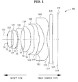
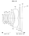
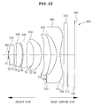
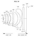
- FIG. 1 is a lateral cross-sectional view schematically showing an internal structure of an imaging lens according to a first preferred embodiment ofthe present invention.
- the imaging lens 100 is configured to include a first lens 110, a second lens 120, a third lens 130, a fourth lens 140, a fifth lens 150, and a sixth lens 160 sequentially disposed from an object side.
- the imaging lens 100 according to the first preferred embodiment of the present invention may further include an aperture stop 105 positioned to be closer to the object side or an image surface side as compared with any one ofthe first to sixth lenses 110 and 160.
- light corresponding to image information of the object sequentially passes through the first lens 110, the aperture stop 105, the second lens 120, the third lens 130, the fourth lens 140, the fifth lens 150, the sixth lens 160, and a filter 170, and is then incident to a light receiving element 180.
- the first lens 110 is formed to have positive (+) power and have a shape in which it is convex toward the object side.
- the second lens 120 is formed to have positive (+) power.
- the third lens 130 is formed to have negative (-) power.
- the fourth lens 140 is formed to have positive (+) power.
- At least one ofthe third and fourth lenses 130 and 140 is formed to have the Abbe number (V) smaller than 30, thereby making it possible to significantly decrease chromatic aberration.
- the present invention is not necessary limited thereto.
- at least one ofthe third and fourth lenses 130 and 140 is formed to have the Abbe number (V) that is in the range of 20 to 30, thereby making it possible to more significantly decrease chromatic aberration.
- the fifth lens 150 may be formed to have positive (+) power and have a shape in which it is convex toward the object side and the image surface side.
- the fifth lens 150 is formed to have a point of inflection on at least one of a surface thereof toward the object side and a surface thereof toward the image surface side.
- the sixth lens 160 is formed to have negative (-) power and have a point of inflection on a surface thereof toward the image surface side.
- first lens 110, the second lens 120, the third lens 130, the fourth lens 140, the fifth lens 150, and the sixth lens 160 may be formed as an aspheric surface.
- present invention is not limited thereto.
- the aperture stop 105 is disposed to be closer to the object side or the image surface side as compared with any one of the first to fifth lenses 110 and 150 and selectively collects incident light to adjust a focal length.
- the aperture stop 105 may be disposed to be closer to the object side or the image surface side as compared with the first lens 110.
- the aperture stop 105 may be disposed between a surface of the first lens 110 toward the object side and a surface of the third lens 130 toward the object side.
- a position ofthe aperture stop 105 according to the first preferred embodiment of the present invention is not limited to the positions according to an example and another example.
- the filter 170 may be an infrared (IR) cut filter.
- IR infrared
- a kind of filter 170 according to the first preferred embodiment of the present invention is not limited thereto.
- the IR cut filter serves to cut radiant heat discharged from external light so as not to be transferred to the light receiving element 180.
- the IR cut filter has a structure in which it transmits a visible ray therethrough and reflects an infrared ray to discharge the infrared ray to the outside.
- the light receiving element 180 having a surface on which an image is formed may be configured of an image sensor converting an optical signal corresponding to a subject image into an electrical signal.
- the image sensor may be a charge coupled device (CCD) or a complementary metal oxide semiconductor (CMOS) sensor.
- CMOS complementary metal oxide semiconductor
- the light receiving element according to the preferred embodiment of the present invention is not limited thereto.
- the imaging lens 100 has optical characteristics as shown in the following Table 1.
- Table 1 Lens surface No. Radius of curvature (mm) Thickness (mm) Refractive index Abbe number Lens shape Remark S 1 infinite 0 - - Flat Stop S2 2.169 0.437 1.544 56.1 Asphere L1 S3 5.712 0.201 Asphere S4 11.693 0.499 1.553 48.6 Asphere L2 S5 -2.849 0.050 Asphere S6 -7.308 0.300 1.615 25.3 Asphere L3 S7 2.926 0.381 Asphere S8 -28.676 0.704 1.564 41.9 Asphere L4 S9 -8.715 0.329 Asphere S10 4.465 0.586 1.544 56.2 Asphere L5 S11 -2.080 0.513 Asphere S12 -1.874 0.380 1.526 53.1 Asphere L6 S13 2.780 0.300 Asphere S14 infinite 0.300 1.516 64.2 Flat Filter S15 infinite 0.600 Flat S16 infinite -
- all surfaces of the first lens 110 (L1), the second lens 120 (L2), the third lens 130 (L3), the fourth lens 140 (L4), the fifth lens 150 (L5), and the sixth lens 160 (L6) ofthe imaging lens 100 according to the first preferred embodiment ofthe present invention are aspheric surfaces.
- S1 means a surface determining a light amount of the imaging lens 100 according to the preferred embodiment of the present invention
- Stop stated in the Remark column of S1 means the aperture stop 105 (S1) used to adjust a light amount.
- the aperture stop 105 is disposed on the surface of the first lens 110 toward the object side, a position of the aperture stop 105 according to the first preferred embodiment of the present invention is not limited thereto.
- the imaging lens 100 according to the preferred embodiment of the present invention is not necessarily limited to including the aperture stop 105.
- Table 2 shows aspheric constant values of aspheric lenses according to the first preferred embodiment ofthe present invention.
- S1 which is the aperture stop 105 (S1) used to adjust the light amount, is flat, such that it does not have an aspheric constant value.
- S14 and S15 which are the filter 170, and S16, which is the image sensor corresponding to the light receiving element 180, are flat, such that they do not have aspheric constant values.
- the aspheric constant values according to the first preferred embodiment of the present invention may be calculated by the following Equation 1.
- Z c ⁇ Y 2 1 + 1 - 1 + K ⁇ c 2 ⁇ Y 2 + A ⁇ Y 4 + B ⁇ Y 6 + C ⁇ Y 8 + D ⁇ Y 10 + E ⁇ Y 12
- Z Length from apex of lens in optical axis direction
- c Basic curvature of lens
- Y Length in direction perpendicular to optical axis
- K Conic Constant
- A, B, C, D, E Aspheric constant
- the entire focal length of the imaging lens 100 according to the first preferred embodiment of the present invention is F and focal lengths of the first lens 110, the second lens 120, the third lens 130, the fourth lens 140, the fifth lens 150, and the sixth lens 160 are F1, F2, F3, F4, F5, and F6, respectively, the respective values are represented by the following Table 3.
- Table 3 Item Entire focal length (F) of imaging lens 4.282 Focal length (F1) of first lens 6.158 Focal length (F2) of second lens 4.193 Focal length (F3) of third lens -3.355 Focal length (F4) of fourth lens 21.906 Focal length (F5) of fifth lens 2.693 Focal length (F6) of second lens -2.079 TTL 5.500
- the imaging lens 100 when it is assumed that a length from an incident surface of the first lens 110 toward the object side to the image surface is TTL and the entire focal length ofthe imaging lens 100 is F, the following Conditional Equation may be satisfied. 0.95 ⁇ TTL / F ⁇ 1.35
- the above Conditional Equation (1) is a relationship equation of TTL and power of the imaging lens 100 according to the first preferred embodiment of the present invention.
- the above Conditional Equation (1) is satisfied, thereby making it possible to form the imaging lens 100 in which a telephoto form is possible.
- the above Conditional Equation (3) is a relationship equation of power of the first and second lenses 110 and 120 according to the first preferred embodiment ofthe present invention.
- the imaging lens 100 is designed to have a value smaller or larger than the above Conditional Equation (3), axial performance is deteriorated, such that marketability is deteriorated and it is difficult to secure optical performance.
- the imaging lens 100 when it is assumed that a synthetic focal length of the third and fourth lenses 130 and 140 is F34 and the entire focal length of the imaging lens 100 is F, the following Conditional Equation may be satisfied. - 2.5 ⁇ F / F ⁇ 34 ⁇ - 0.4
- the above Conditional Equation (4) is a relationship equation of power of the third and fourth lenses 130 and 140 according to the first preferred embodiment of the present invention.
- the imaging lens 100 is designed to have a value smaller or larger than the above Conditional Equation (4), chromatic aberration and off-axis aberration are generated.
- the imaging lens 100 when it is assumed that a focal length ofthe first lens 110 is F1 and the entire focal length ofthe imaging lens 100 is F, the following Conditional Equation may be satisfied. 0 ⁇ F / F ⁇ 1 ⁇ 1.5
- the above Conditional Equation (5) is a relationship equation of power of the first lens 110 according to the first preferred embodiment ofthe present invention.
- a optical power is decreased, such that sensitivity is decreased.
- the imaging lens 100 when it is assumed that a focal length of the third lens 130 is F3 and the entire focal length ofthe imaging lens 100 is F, the following Conditional Equation may be satisfied. 0.2 ⁇ F / F ⁇ 3 ⁇ 2.5
- the above Conditional Equation (6) is a relationship equation of power of the third lens 130 according to the first preferred embodiment ofthe present invention.
- the imaging lens 100 is designed to have a value smaller or larger than the above Conditional Equation (6), a optical power is dispersed, such that sensitivity is decreased.
- the imaging lens 100 when it is assumed that a focal length ofthe fifth lens 150 is F5, a focal length of the sixth lens 160 is F6, and the entire focal length of the imaging lens 100 is F, the following Conditional Equation may be satisfied. 0.3 ⁇ F / F ⁇ 5 + F / F ⁇ 6 ⁇ 6.0
- the above Conditional Equation (7) is a relationship equation of power of the fifth and sixth lenses 150 and 160 according to the first preferred embodiment of the present invention.
- the above Conditional Equation (7) is satisfied, thereby making it possible to form the imaging lens 100 in which a telephoto form is possible.
- the imaging lens 100 when it is assumed that a length from an incident surface of the first lens 110 toward the object side to the image surface is TTL and an image height is ImgH, the following Conditional Equation may be satisfied. 0.35 ⁇ TTL / 2 ⁇ ImgH ⁇ 0.95
- the above Conditional Equation (8) is a relationship equation of TTL and power of the imaging lens 100 according to the first preferred embodiment of the present invention.
- the above Conditional Equation (8) is satisfied, thereby making it possible to form the imaging lens 100 in a slim form.
- the above Conditional Equation (9) is a relationship equation for the field of view of the imaging lens 100 according to the first preferred embodiment of the present invention.
- the above Conditional Equation (9) is satisfied, thereby making it possible to form the imaging lens 100 in a slim form and a pseudo-wide angle form.
- the above Conditional Equation (10) is a relationship equation for dispersion of the first and second lenses 110 and 120 and the third and fourth lenses 130 and 140 according to the first preferred embodiment of the present invention.
- the above Conditional Equation (10) is satisfied, thereby making it possible to effectively decrease chromatic aberration.
- the imaging lens 100 when it is assumed that a focal length ofthe third lens 130 is F3, a focal length ofthe fourth lens 140 is F4, and the entire focal length ofthe imaging lens 100 is F, the following Conditional Equation may be satisfied. 0 ⁇ F / F ⁇ 3 + F / F ⁇ 4 ⁇ 3
- the above Conditional Equation (11) is a relationship equation for optical powers ofthe third and fourth lenses 130 and 140 according to the first preferred embodiment of the present invention.
- the above Conditional Equation (11) is satisfied, thereby making it possible to decrease aberration.
- the imaging lens 100 when it is assumed that a radius of curvature of a surface of the first lens 110 toward the image surface side is r12 and the entire focal length ofthe imaging lens 100 is F, the following Conditional Equation may be satisfied. 0.15 ⁇ r ⁇ 12 / F ⁇ 0.9
- the above Conditional Equation (12) is a relationship equation of power for the radius of curvature of the surface of the first lens 110 according to the first preferred embodiment ofthe present invention toward the image surface side.
- the above Conditional Equation (12) is satisfied, thereby making it possible to form the imaging lens 100 having excellent optical characteristics.
- the imaging lens 100 when it is assumed that a focal length of the first lens 110 is F1 and a focal length ofthe third lens 130 is F3, the following Conditional Equation maybe satisfied. 0 ⁇ F ⁇ 1 / F ⁇ 3 ⁇ 25
- the above Conditional Equation (13) is a relationship equation of power of the first and third lenses 110 and 130 according to the first preferred embodiment of the present invention.
- the above Conditional Equation (13) is satisfied, thereby making it possible to form the imaging lens 100 having excellent optical characteristics.
- the imaging lens 100 when it is assumed that a radius of curvature of a surface of the fifth lens 150 toward the object side is r9 and a radius of curvature of a surface ofthe fifth lens 150 toward the image surface side is r10, the following Conditional Equation may be satisfied. 0 ⁇ r ⁇ 9 - r ⁇ 10 / r ⁇ 9 + r ⁇ 10 ⁇ 6
- the above Conditional Equation (14) is a relationship equation ofpower ofthe fifth lens 150 according to the first preferred embodiment ofthe present invention.
- the above Conditional Equation (14) is satisfied, thereby making it possible to form the fifth lens 150 having the positive (+) power.
- the imaging lens 100 when it is assumed that the entire focal length ofthe imaging lens 100 is F, a focal length of the first lens 110 is F1, and a focal length of the second lens 120 is F2, the following Conditional Equation may be satisfied. 0.2 ⁇ F / F ⁇ 1 + F / F ⁇ 2 ⁇ 4
- the above Conditional Equation (15) is a relationship equation for determining the entire power of the imaging lens 100 according to the first preferred embodiment of the present invention.
- the above Conditional Equation (15) is satisfied, thereby making it possible to form the imaging lens 100 having excellent optical characteristics.
- a focal length of the first lens 110 is F1
- a focal length of the second lens 120 is F2
- a focal length of the third lens 130 is F3
- a focal length of the fourth lens 140 is F4
- the following Conditional Equation may be satisfied. 0 ⁇ F ⁇ 1 + F ⁇ 2 / F ⁇ 3 + F ⁇ 4 ⁇ 30
- the above Conditional Equation (16) is a relationship equation of power of the first lens 110, the second lens 120, the third lens 130, and the fourth lens 140 according to the first preferred embodiment of the present invention.
- the above Conditional Equation (16) is satisfied, thereby making it possible to form the imaging lens 100 having excellent optical characteristics.
- a focal length of the fourth lens 140 is F4
- a focal length of the fifth lens 150 is F5
- a focal length of the sixth lens 160 is F6
- the following Conditional Equation may be satisfied. 0.20 ⁇ F / F ⁇ 4 + F / F ⁇ 5 + F / F ⁇ 6 ⁇ 7.5
- the above Conditional Equation (17) is a relationship equation of power of the fourth lens 140, the fifth lens 150, and the sixth lens 160 according to the first preferred embodiment of the present invention.
- the above Conditional Equation (17) is satisfied, thereby making it possible to form the imaging lens 100 having excellent optical characteristics.
- the imaging lens 100 when it is assumed that the entire focal length of the imaging lens 100 is F and a length between a surface of the first lens 110 toward the object side and a surface of the sixth surface 160 toward the image surface side on an optical axis is DL, the following Conditional Equation may be satisfied. 0.7 ⁇ DL / F ⁇ 1.2
- the imaging lens 100 when it is assumed that the Abbe number of the fourth lens 140 is v4 and the Abbe number ofthe fifth lens 150 is v5, the following Conditional Equation may be satisfied. 42 ⁇ v ⁇ 4 + v ⁇ 5 ⁇ 115
- the above Conditional Equation (19) is a relationship equation for dispersion of the fourth and fifth lenses 140 and 150 according to the first preferred embodiment of the present invention.
- the above Conditional Equation (19) is satisfied, thereby making it possible to form the imaging lens 100 having excellent optical characteristics.
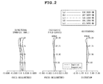
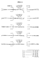
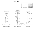
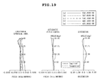
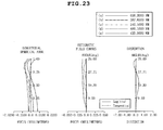
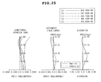
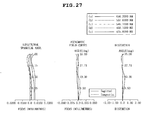
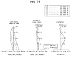
- FIGS. 2 and 3 are graphs showing aberration characteristics according to the first preferred embodiment of the present invention.
- the aberration characteristics are shown by representing a plurality of wavelengths by a plurality of colors.
- FIG. 2 is a graph obtained by measuring longitudinal spherical aberration, astigmatic field curve, and distortion according to the first preferred embodiment of the present invention.
- FIG. 3 is a graph obtained by measuring coma aberration according to the first preferred embodiment ofthe present invention.
- the graph obtained by measuring the longitudinal spherical aberration shows longitudinal spherical aberration depending on each wavelength.
- each wavelength is adjacent to a vertical axis, characteristics of the longitudinal spherical aberration are excellent.
- the graph obtained by measuring the astigmatic field curve shows aberration characteristics of a direction component (X) of x axis light and a direction component (Y) of y axis light according to an image surface height (ANGLE) viewed from the object side, which is a vertical axis, and a focus (FOCUS) position, which is a horizontal axis.
- ANGLE image surface height
- FOCUS focus
- the graph obtained by measuring the distortion shows distortion characteristics, which are a horizontal axis, according to an image surface height (ANGLE) viewed from the object side.
- ANGLE image surface height
- the graph obtained by measuring the coma aberration shows tangential and sagittal aberration characteristics depending on each wavelength according to an image surface height.
- the graph obtained by measuring the coma aberration shows tangential and sagittal aberration characteristics depending on each wavelength according to an image surface height.
- FIG. 4 is a lateral cross-sectional view schematically showing an internal structure of an imaging lens according to a second preferred embodiment ofthe present invention.
- the imaging lens 200 is configured to include a first lens 210, a second lens 220, a third lens 230, a fourth lens 240, a fifth lens 250, and a sixth lens 260 sequentially disposed from an object side.
- the imaging lens 200 according to the second preferred embodiment of the present invention may further include an aperture stop 205 positioned to be closer to the object side or an image surface side as compared with any one ofthe first to sixth lenses 210 and 260.
- light corresponding to image information ofthe object sequentially passes through the first lens 210, the aperture stop 205, the second lens 220, the third lens 230, the fourth lens 240, the fifth lens 250, the sixth lens 260, and a filter 270, and is then incident to a light receiving element 280.
- the first lens 210 is formed to have positive (+) power and have a shape in which it is convex toward the object side.
- the second lens 220 is formed to have positive (+) power.
- each of the third and fourth lenses 230 and 240 may be formed to have negative (-) power, but the present invention is not necessarily limited thereto.
- each ofthe third and fourth lenses 230 and 240 may be formed to have positive (+) power.
- At least one ofthe third and fourth lenses 230 and 240 is formed to have the Abbe number (V) smaller than 30, thereby making it possible to significantly decrease chromatic aberration.
- the present invention is not necessary limited thereto.
- at least one ofthe third and fourth lenses 230 and 240 is formed to have the Abbe number (V) that is in the range of 20 to 30, thereby making it possible to more significantly decrease chromatic aberration.
- the fifth lens 250 may be formed to have positive (+) power and have a shape in which it is convex toward the object side and the image surface side.
- the fifth lens 250 is formed to have a point of inflection on at least one of a surface thereof toward the object side and a surface thereoftoward the image surface side.
- the sixth lens 260 is formed to have negative (-) power, be concave toward the image surface side, and have a point of inflection on a surface thereoftoward the image surface side.
- the first lens 210, the second lens 220, the third lens 230, the fourth lens 240, the fifth lens 250, and the sixth lens 260 may be formed as an aspheric surface.
- the present invention is not limited thereto.
- the aperture stop 205 is disposed to be closer to the object side or the image surface side as compared with any one of the first to fifth lenses 210 and 250 and selectively collects incident light to adjust a focal length.
- the aperture stop 205 may be disposed to be closer to the object side or the image surface side as compared with the first lens 210.
- the aperture stop 205 may be disposed between a surface of the first lens 210 toward the object side and a surface of the third lens 23 0 toward the object side.
- a position of the aperture stop 205 according to the second preferred embodiment of the present invention is not limited to the positions according to an example and another example.
- the filter 270 may be an infrared (IR) cut filter.
- IR infrared
- a kind of filter 270 according to the second preferred embodiment ofthe present invention is not limited thereto.
- the IR cut filter serves to cut radiant heat discharged from external light so as not to be transferred to the light receiving element 280.
- the IR cut filter has a structure in which it transmits a visible ray therethrough and reflects an infrared ray to discharge the infrared ray to the outside.
- the light receiving element 280 having a surface on which an image is formed may be configured of an image sensor converting an optical signal corresponding to a subject image into an electrical signal.
- the image sensor may be a charge coupled device (CCD) or a complementary metal oxide semiconductor (CMOS) sensor.
- CMOS complementary metal oxide semiconductor
- the light receiving element according to the preferred embodiment of the present invention is not limited thereto.
- the imaging lens 200 has optical characteristics as shown in the following Table 4.
- Table 4 Lens surface No. Radius of curvature (mm) Thickness (mm) Refractive index Abbe number Lens shape Remark S1 infinite 0 - - Flat Stop S2 4.993 0.421 1.553 48.7 Asphere L1 S3 -4.538 0.050 Asphere S4 -362.542 0.634 1.544 56.1 Asphere L2 S5 -2.196 0.050 Asphere S6 -4.304 0.300 1.615 25.9 Asphere L3 S7 8.241 0.503 Asphere S8 -1.803 0.523 1.606 26.7 Asphere L4 S9 -3.616 0.166 Asphere S10 5.827 0.837 1.544 55.9 Asphere L5 S11 -1.782 0.516 Asphere S12 -2.055 0.300 1.519 55.6 Asphere L6 S13 2.814 0.300 Asphere S14 infinite 0.300 1.516 64.2 Flat Filter S15 infinite 0.600 Flat S16
- all surfaces of the first lens 210 (L1), the second lens 220 (L2), the third lens 230 (L3), the fourth lens 240 (L4), the fifth lens 250 (L5), and the sixth lens 260 (L6) of the imaging lens 200 according to the second preferred embodiment of the present invention are aspheric surfaces.
- S1 means a surface determining a light amount of the imaging lens 200 according to the preferred embodiment of the present invention
- Stop stated in the Remark column of S1 means the aperture stop 205 (S1) used to adjust a light amount.
- the aperture stop 205 is disposed on the surface of the first lens 210 toward the object side, a position of the aperture stop 205 according to the second preferred embodiment of the present invention is not limited thereto.
- the imaging lens 200 according to the second preferred embodiment ofthe present invention is not necessarily limited to including the aperture stop 205.
- Table 5 shows aspheric constant values of aspheric lenses according to the second preferred embodiment ofthe present invention.
- S1 which is the aperture stop 205 (S1) used to adjust the light amount, is flat, such that it does not have an aspheric constant value.
- S14 and S15 which are the filter 270
- S16 which is the image sensor corresponding to the light receiving element 280
- S14 and S15 are flat, such that they do not have aspheric constant values.
- the entire focal length of the imaging lens 200 according to the second preferred embodiment ofthe present invention is F and the focal lengths ofthe first lens 210, the second lens 220, the third lens 230, the fourth lens 240, the fifth lens 250, and the sixth lens 260 are F1, F2, F3, F4, F5, and F6, respectively, the respective values are represented by the following Table 6.
- the imaging lens 200 when it is assumed that a length from an incident surface of the first lens 210 toward the object side to the image surface is TTL and the entire focal length ofthe imaging lens 200 is F, the following Conditional Equation may be satisfied. 0.95 ⁇ TTL / F ⁇ 1.35
- the above Conditional Equation (1) is a relationship equation of TTL and power of the imaging lens 200 according to the second preferred embodiment of the present invention.
- the above Conditional Equation (1) is satisfied, thereby making it possible to form the imaging lens 200 in which a telephoto form is possible.
- the above Conditional Equation (3) is a relationship equation of power of the first and second lenses 210 and 220 according to the second preferred embodiment of the present invention.
- the imaging lens 200 is designed to have a value smaller or larger than the above Conditional Equation (3), axial performance is deteriorated, such that marketability is deteriorated and it is difficult to secure optical performance.
- the imaging lens 200 when it is assumed that a synthetic focal length of the third and fourth lenses 230 and 240 is F34 and the entire focal length of the imaging lens 200 is F, the following Conditional Equation may be satisfied. - 2.5 ⁇ F / F ⁇ 34 ⁇ - 0.4
- the above Conditional Equation (4) is a relationship equation of power of the third and fourth lenses 230 and 240 according to the second preferred embodiment of the present invention.
- the imaging lens 200 is designed to have a value smaller or larger than the above Conditional Equation (4), chromatic aberration and off-axis aberration are not appropriately corrected, such that marketability is deteriorated and it is difficult to secure optical performance.
- the imaging lens 200 when it is assumed that a focal length of the first lens 210 is F1 and the entire focal length of the imaging lens 200 is F, the following Conditional Equation may be satisfied. 0 ⁇ F / F ⁇ 1 ⁇ 1.5
- the above Conditional Equation (5) is a relationship equation of power of the first lens 210 according to the second preferred embodiment of the present invention.
- a optical power is decreased, such that sensitivity is decreased.
- the imaging lens 200 when it is assumed that a focal length of the third lens 230 is F3 and the entire focal length of the imaging lens 200 is F, the following Conditional Equation may be satisfied. 0.2 ⁇ F / F ⁇ 3 ⁇ 2.5
- the above Conditional Equation (6) is a relationship equation of power of the third lens 230 according to the second preferred embodiment of the present invention.
- the imaging lens 200 is designed to have a value smaller or larger than the above Conditional Equation (6), a optical power is dispersed, such that sensitivity is decreased.
- the imaging lens 200 when it is assumed that a focal length of the fifth lens 2 50 is F5, a focal length of the sixth lens 260 is F6, and the entire focal length of the imaging lens 200 is F, the following Conditional Equation may be satisfied. 0.3 ⁇ F / F ⁇ 5 + F / F ⁇ 6 ⁇ 6.0
- the above Conditional Equation (7) is a relationship equation of power of the fifth and sixth lenses 250 and 260 according to the second preferred embodiment ofthe present invention.
- the above Conditional Equation (7) is satisfied, thereby making it possible to form the imaging lens 200 in which a telephoto form is possible.
- the imaging lens 200 when it is assumed that a length from an incident surface of the first lens 210 toward the object side to the image surface is TTL and an image height is ImgH, the following Conditional Equation may be satisfied. 0.35 ⁇ TTL / 2 ⁇ ImgH ⁇ 0.95
- the above Conditional Equation (8) is a relationship equation of TTL and power of the imaging lens 200 according to the second preferred embodiment of the present invention.
- the above Conditional Equation (8) is satisfied, thereby making it possible to form the imaging lens 200 in a slim form.
- the above Conditional Equation (9) is a relationship equation for the field of view of the imaging lens 200 according to the second preferred embodiment of the present invention.
- the above Conditional Equation (9) is satisfied, thereby making it possible to form the imaging lens 200 in a slim form and a pseudo-wide angle form.
- the above Conditional Equation (10) is a relationship equation for dispersion of the first and second lenses 210 and 220 and the third and fourth lenses 230 and 240 according to the second preferred embodiment of the present invention.
- the above Conditional Equation (10) is satisfied, thereby making it possible to effectively decrease chromatic aberration.
- the imaging lens 200 when it is assumed that a focal length of the third lens 230 is F3, a focal length of the fourth lens 240 is F4, and the entire focal length of the imaging lens 200 is F, the following Conditional Equation may be satisfied. 0 ⁇ F / F ⁇ 3 + F / F ⁇ 4 ⁇ 3
- the above Conditional Equation (11) is a relationship equation for optical powers ofthe third and fourth lenses 230 and 240 according to the second preferred embodiment of the present invention.
- the above Conditional Equation (11) is satisfied, thereby making it possible to decrease aberration.
- the imaging lens 200 when it is assumed that a radius of curvature of a surface of the first lens 210 toward the image surface side is r12 and the entire focal length ofthe imaging lens 200 is F, the following Conditional Equation may be satisfied. 0.15 ⁇ r ⁇ 12 / F ⁇ 0.9
- the above Conditional Equation (12) is a relationship equation of power for the radius of curvature ofthe surface ofthe first lens 210 according to the second preferred embodiment of the present invention toward the image surface side.
- the above Conditional Equation (12) is satisfied, thereby making it possible to form the imaging lens 200 having excellent optical characteristics.
- the imaging lens 200 when it is assumed that a focal length ofthe first lens 210 is F1 and a focal length of the third lens 230 is F3, the following Conditional Equation may be satisfied. 0 ⁇ F ⁇ 1 / F ⁇ 3 ⁇ 25
- the above Conditional Equation (13) is a relationship equation of power of the first and third lenses 210 and 230 according to the second preferred embodiment ofthe present invention.
- the above Conditional Equation (13) is satisfied, thereby making it possible to form the imaging lens 200 having excellent optical characteristics.
- the imaging lens 200 when it is assumed that a radius of curvature of a surface of the fifth lens 250 toward the object side is r9 and a radius of curvature of a surface of the fifth lens 250 toward the image surface side is r10, the following Conditional Equation may be satisfied. 0 ⁇ r ⁇ 9 - r ⁇ 10 / r ⁇ 9 + r ⁇ 10 ⁇ 6
- the above Conditional Equation (14) is a relationship equation ofpower ofthe fifth lens 250 according to the second preferred embodiment of the present invention.
- the above Conditional Equation (14) is satisfied, thereby making it possible to form the fifth lens 250 having the positive (+) power.
- the imaging lens 200 when it is assumed that the entire focal length ofthe imaging lens 200 is F, a focal length of the first lens 210 is F1, and a focal length of the second lens 220 is F2, the following Conditional Equation may be satisfied. 0.2 ⁇ F / F ⁇ 1 + F / F ⁇ 2 ⁇ 4
- the above Conditional Equation (15) is a relationship equation for determining the entire power of the imaging lens 200 according to the second preferred embodiment of the present invention.
- the above Conditional Equation (15) is satisfied, thereby making it possible to form the imaging lens 200 having excellent optical characteristic s.
- a focal length of the first lens 210 is F1
- a focal length ofthe second lens 220 is F2
- a focal length ofthe third lens 230 is F3
- a focal length of the fourth lens 240 is F4
- the following Conditional Equation may be satisfied. 0 ⁇ F ⁇ 1 + F ⁇ 2 / F ⁇ 3 + F ⁇ 4 ⁇ 30
- the above Conditional Equation (16) is a relationship equation of power of the first lens 210, the second lens 220, the third lens 230, and the fourth lens 240 according to the second preferred embodiment of the present invention.
- the above Conditional Equation (16) is satisfied, thereby making it possible to form the imaging lens 200 having excellent optica 1 characteristics.
- the imaging lens 200 when it is assumed that the entire focal length ofthe imaging lens 200 is F, a focal length of the fourth lens 240 is F4, a focal length of the fifth lens 250 is F5, and a focal length of the sixth lens 260 is F6, the following Conditional Equation may be satisfied. 0.20 ⁇ F / F ⁇ 4 + F / F ⁇ 5 + F / F ⁇ 6 ⁇ 7.5
- the above Conditional Equation (17) is a relationship equation of power of the fourth lens 240, the fifth lens 250, and the sixth lens 260 according to the second preferred embodiment of the present invention.
- the above Conditional Equation (17) is satisfied, thereby making it possible to form the imaging lens 200 having excellent optical characteristics.
- the imaging lens 200 when it is assumed that the entire focal length of the imaging lens 200 is F and a length between a surface of the first lens 210 toward the object side and a surface of the sixth surface 260 toward the image surface side on an optical axis is DL, the following Conditional Equation may be satisfied. 0.7 ⁇ DL / F ⁇ 1.2
- the imaging lens 200 when it is assumed that the Abbe number of the fourth lens 240 is v4 and the Abbe number ofthe fifth lens 250 is v5, the following Conditional Equation maybe satisfied. 42 ⁇ v ⁇ 4 + v ⁇ 5 ⁇ 115
- the above Conditional Equation (19) is a relationship equation for dispersion of the fourth and fifth lenses 240 and 250 according to the second preferred embodiment ofthe present invention.
- the above Conditional Equation (19) is satisfied, thereby making it possible to form the imaging lens 200 having excellent optical characteristics.
- FIGS. 5 and 6 are graphs showing aberration characteristics according to the second preferred embodiment of the present invention.
- the aberration characteristics are shown by representing a plurality of wavelengths by a plurality of colors.
- FIG. 5 is a graph obtained by measuring longitudinal spherical aberration, astigmatic field curve, and distortion according to the second preferred embodiment of the present invention.
- FIG. 6 is a graph obtained by measuring coma aberration according to the second preferred embodiment ofthe present invention.
- the graph obtained by measuring the longitudinal spherical aberration shows longitudinal spherical aberration depending on each wavelength.
- each wavelength is adjacent to a vertical axis, characteristics of the longitudinal spherical aberration are excellent.
- the graph obtained by measuring the astigmatic field curve shows aberration characteristics of a direction component (X) of x axis light and a direction component (Y) of y axis light according to an image surface height (ANGLE) viewed from the object side, which is a vertical axis, and a focus (FOCUS) position, which is a horizontal axis.
- ANGLE image surface height
- FOCUS focus
- the graph obtained by measuring the distortion shows distortion characteristics, which are a horizontal axis, according to an image surface height (ANGLE) viewed from the object side.
- ANGLE image surface height
- the graph obtained by measuring the coma aberration shows tangential and sagittal aberration characteristics depending on each wavelength according to an image surface height.
- the graph obtained by measuring the coma aberration shows tangential and sagittal aberration characteristics depending on each wavelength according to an image surface height.
- FIG. 7 is a lateral cross-sectional view schematically showing an internal structure of an imaging lens according to a third preferred embodiment of the present invention.
- the imaging lens 300 is configured to include a first lens 310, a second lens 320, a third lens 330, a fourth lens 340, a fifth lens 350, and a sixth lens 360 sequentially disposed from an object side.
- the imaging lens 300 according to the third preferred embodiment of the present invention may further include an aperture stop 305 positioned to be closer to the object side or an image surface side as compared with any one ofthe first to sixth lenses 310 and 360.
- light corresponding to image information of the object sequentially passes through the first lens 310, the ap erture stop 305, the second lens 320, the third lens 330, the fourth lens 340, the fifth lens 350, the sixth lens 360, and a filter 370, and is then incident to a light receiving element 380.
- the first lens 310 is formed to have positive (+) power and have a shape in which it is convex toward the object side.
- the second lens 320 is formed to have positive (+) power.
- the third lens 330 is formed to have positive (+) power.
- the fourth lens 340 is formed to have negative (-) power.
- At least one ofthe third and fourth lenses 330 and 340 is formed to have the Abbe number (V) smaller than 30, thereby making it possible to significantly decrease chromatic aberration.
- the present invention is not necessary limited thereto.
- at least one ofthe third and fourth lenses 330 and 340 is formed to have the Abbe number (V) that is in the range of 20 to 30, thereby making it possible to more significantly decrease chromatic aberration.
- the fifth lens 350 may be formed to have positive (+) power and have a shape in which it is convex toward the object side and the image surface side.
- the fifth lens 350 is formed to have a point of inflection on at least one of a surface thereof toward the object side and a surface thereof toward the image surface side.
- the sixth lens 360 is formed to have negative (-) power, be concave toward the image surface side, and have a point of inflection on a surface thereoftoward the image surface side.
- the first lens 310, the second lens 320, the third lens 330, the fourth lens 340, the fifth lens 350, and the sixth lens 360 may be formed as an aspheric surface.
- the present invention is not limited thereto.
- the aperture stop 305 is disposed to be closer to the object side or the image surface side as compared with any one of the first to fifth lenses 310 and 350 and selectively collects incident light to adjust a focal length.
- the aperture stop 305 may be disposed to be closer to the object side or the image surface side as compared with the first lens 310.
- the aperture stop 305 may be disposed between a surface of the first lens 310 toward the object side and a surface of the third lens 330 toward the object side.
- a position of the aperture stop 305 according to the third preferred embodiment of the present invention is not limited to the positions according to an example and another example.
- the filter 370 may be an infrared (IR) cut filter.
- IR infrared
- a kind of filter 370 according to the third preferred embodiment of the present invention is not limited thereto.
- the IR cut filter serves to cut radiant heat discharged from external light so as not to be transferred to the light receiving element 380.
- the IR cut filter has a structure in which it transmits a visible ray therethrough and reflects an infrared ray to discharge the infrared ray to the outside.
- the light receiving element 380 having a surface on which an image is formed may be configured of an image sensor converting an optical signal corresponding to a subject image into an electrical signal.
- the image sensor may be a charge coupled device (CCD) or a complementary metal oxide semiconductor (CMOS) sensor.
- CMOS complementary metal oxide semiconductor
- the light receiving element according to the preferred embodiment of the present invention is not limited thereto.
- the imaging lens 300 has optical characteristics as shown in the following Table 7.
- Table 7 Lens surface No. Radius of curvature (mm) Thickness (mm) Refractive index Abbe number Lens shape Remark S1 infinite 0 - - Flat Stop S2 2.191 0.430 1.544 56.1 Asphere L1 S3 2.819 0.111 Asphere S4 2.199 0.420 1.544 56.1 Asphere L2 S5 5.717 0.156 Asphere S6 -12.830 0.520 1.544 56.1 Asphere L3 S7 -2.070 0.192 Asphere S8 -1.216 0.467 1.639 23.3 Asphere L4 S9 -5.562 0.212 Asphere S10 6.132 0.677 1.569 39.5 Asphere L5 S11 -1.858 0.736 Asphere S12 -2.869 0.380 1.507 60.1 Asphere L6 S13 2.820 0.300 Asphere S14 infinite 0.300 1.516 64.2 Flat Filter S15 infinite 0.600 Flat S16 infinite - - - Flat Image sensor
- all surfaces of the first lens 310 (L1), the second lens 320 (L2), the third lens 330 (L3), the fourth lens 340 (L4), the fifth lens 350 (L5), and the sixth lens 360 (L6) ofthe imaging lens 300 according to the third preferred embodiment of the present invention are aspheric surfaces.
- S1 means a surface determining a light amount of the imaging lens 300 according to the preferred embodiment of the present invention
- Stop stated in the Remark column of S1 means the aperture stop 305 (S1) used to adjust a light amount.
- the aperture stop 305 is disposed on the surface of the first lens 310 toward the object side, a position of the aperture stop 305 according to the third preferred embodiment of the present invention is not limited thereto.
- the imaging lens 300 according to the third preferred embodiment ofthe present invention is not necessarily limited to including the aperture stop 305.
- Table 8 shows aspheric constant values of aspheric lenses according to the third preferred embodiment ofthe present invention.
- S 1 which is the aperture stop 305 (S 1) used to adjust the light amount, is flat, such that it does not have an aspheric constant value.
- S14 and S15 which are the filter 370
- S16 which is the image sensor corresponding to the light receiving element 380
- S14 and S15 are flat, such that they do not have aspheric constant values.
- the entire focal length of the imaging lens 300 according to the third preferred embodiment ofthe present invention is F and focal lengths ofthe first lens 310, the second lens 320, the third lens 330, the fourth lens 340, the fifth lens 350, and the sixth lens 360 are F1, F2, F3, F4, F5, and F6, respectively, the respective values are represented by the following Table 9.
- Table 9 Item Entire focal length (F) of imaging lens 4.283 Focal length (F1) of first lens 14.575 Focal length (F2) of second lens 6.302 Focal length (F3) of third lens 4.461 Focal length (F4) of fourth lens -2.541 Focal length (F5) of fifth lens 2.583 Focal length (F6) of second lens -2.741 TTL 5.499
- the imaging lens 300 when it is assumed that a length from an incident surface of the first lens 310 toward the object side to the image surface is TTL and the entire focal length ofthe imaging lens 300 is F, the following Conditional Equation may be satisfied. 0.95 ⁇ TTL / F ⁇ 1.35
- the above Conditional Equation (1) is a relationship equation of TTL and power of the imaging lens 300 according to the third preferred embodiment of the present invention.
- the above Conditional Equation (1) is satisfied, thereby making it possible to form the imaging lens 300 in which a telephoto form is possible.
- the above Conditional Equation (3) is a relationship equation of power of the first and second lenses 310 and 320 according to the third preferred embodiment ofthe present invention.
- the imaging lens 300 is designed to have a value smaller or larger than the above Conditional Equation (3), axial performance is deteriorated, such that marketability is deteriorated and it is difficult to secure optical performance.
- the imaging lens 300 when it is assumed that a synthetic focal length of the third and fourth lenses 330 and 340 is F34 and the entire focal length of the imaging lens 300 is F, the following Conditional Equation may be satisfied. - 2.5 ⁇ F / F ⁇ 34 ⁇ - 0.4
- the above Conditional Equation (4) is a relationship equation of power of the third and fourth lenses 330 and 340 according to the third preferred embodiment of the present invention.
- the imaging lens 300 is designed to have a value smaller or larger than the above Conditional Equation (4), chromatic aberration and off-axis are generated, such that marketability is deteriorated and it is difficult to secure optical performance.
- the imaging lens 300 when it is assumed that a focal length ofthe first lens 310 is F1 and the entire focal length ofthe imaging lens 300 is F, the following Conditional Equation may be satisfied. 0 ⁇ F / F ⁇ 1 ⁇ 1.5
- the above Conditional Equation (5) is a relationship equation of power of the first lens 310 according to the third preferred embodiment of the present invention.
- the imaging lens 300 is designed to have a value smaller or larger than the above Conditional Equation (5), a optical power is decreased, such that sensitivity is decreased.
- the imaging lens 300 when it is assumed that a focal length of the third lens 330 is F3 and the entire focal length ofthe imaging lens 300 is F, the following Conditional Equation may be satisfied. 0.2 ⁇ F / F ⁇ 3 ⁇ 2.5
- the above Conditional Equation (6) is a relationship equation of power of the third lens 330 according to the third preferred embodiment of the present invention.
- the imaging lens 300 is designed to have a value smaller or larger than the above Conditional Equation (6), a optical power is dispersed, such that sensitivity is decreased.
- the imaging lens 300 when it is assumed that a focal length ofthe fifth lens 350 is F5, a focal length of the sixth lens 360 is F6, and the entire focal length of the imaging lens 300 is F, the following Conditional Equation may be satisfied. 0.3 ⁇ F / F ⁇ 5 + F / F ⁇ 6 ⁇ 6.0
- the above Conditional Equation (7) is a relationship equation of power of the fifth and sixth lenses 350 and 360 according to the third preferred embodiment of the present invention.
- the above Conditional Equation (7) is satisfied, thereby making it possible to form the imaging lens 300 in which a telephoto form is possible.
- the imaging lens 300 when it is assumed that a length from an incident surface of the first lens 310 toward the object side to the image surface is TTL and an image height is ImgH, the following Conditional Equation may be satisfied. 0.35 ⁇ TTL / 2 ⁇ ImgH ⁇ 0.95
- the above Conditional Equation (8) is a relationship equation of TTL and power of the imaging lens 300 according to the third preferred embodiment of the present invention.
- the above Conditional Equation (8) is satisfied, thereby making it possible to form the imaging lens 300 in a slim form.
- the above Conditional Equation (9) is a relationship equation for the field of view of the imaging lens 300 according to the third preferred embodiment of the present invention.
- the above Conditional Equation (9) is satisfied, thereby making it possible to form the imaging lens 300 in a slim form and a pseudo-wide angle form.
- the imaging lens 300 when it is assumed that an average of the Abbe numbers of the first and second lenses 310 and 320 is v12 and an average of the Abbe numbers of the third and fourth lenses 330 and 340 is v34, the following Conditional Equation may be satisfied. 10 ⁇ v ⁇ 12 - v ⁇ 34 ⁇ 45
- the above Conditional Equation (10) is a relationship equation for dispersion of the first and second lenses 310 and 320 and the third and fourth lenses 330 and 340 according to the third preferred embodiment of the present invention.
- the above Conditional Equation (10) is satisfied, thereby making it possible to effectively decrease chromatic aberration.
- the imaging lens 300 when it is assumed that a focal length ofthe third lens 330 is F3, a focal length of the fourth lens 340 is F4, and the entire focal length of the imaging lens 300 is F, the following Conditional Equation may be satisfied. 0 ⁇ F / F ⁇ 3 + F / F ⁇ 4 ⁇ 3
- the above Conditional Equation (11) is a relationship equation for optical powers ofthe third and fourth lenses 330 and 340 according to the third preferred embodiment of the present invention.
- the above Conditional Equation (11) is satisfied, thereby making it possible to decrease aberration.
- the imaging lens 300 when it is assumed that a radius of curvature of a surface of the first lens 310 toward the image surface side is r12 and the entire focal length ofthe imaging lens 300 is F, the following Conditional Equation may be satisfied. 0.15 ⁇ r ⁇ 12 / F ⁇ 0.9
- the above Conditional Equation (12) is a relationship equation of power for the radius of curvature of the surface of the first lens 310 according to the third preferred embodiment of the present invention toward the image surface side.
- the above Conditional Equation (12) is satisfied, thereby making it possible to form the imaging lens 300 having excellent optical characteristics.
- the imaging lens 300 when it is assumed that a focal length of the first lens 310 is F1 and a focal length ofthe third lens 330 is F3, the following Conditional Equation maybe satisfied. 0 ⁇ F ⁇ 1 / F ⁇ 3 ⁇ 25
- the above Conditional Equation (13) is a relationship equation of power of the first and third lenses 310 and 330 according to the third preferred embodiment of the present invention.
- the above Conditional Equation (13) is satisfied, thereby making it possible to form the imaging lens 300 having excellent optical characteristics.
- the imaging lens 300 when it is assumed that a radius of curvature of a surface ofthe fifth lens 350 toward the object side is r9 and a radius of curvature of a surface ofthe fifth lens 350 toward the image surface side is r10, the following Conditional Equation may be satisfied. 0 ⁇ r ⁇ 9 - r ⁇ 10 / r ⁇ 9 + r ⁇ 10 ⁇ 6
- the above Conditional Equation (14) is a relationship equation ofpower ofthe fifth lens 350 according to the third preferred embodiment of the present invention.
- the above Conditional Equation (14) is satisfied, thereby making it possible to form the fifth lens 350 having the positive (+) power.
- the imaging lens 300 when it is assumed that the entire focal length ofthe imaging lens 300 is F, a focal length of the first lens 310 is F1, and a focal length of the second lens 320 is F2, the following Conditional Equation may be satisfied. 0.2 ⁇ F / F ⁇ 1 + F / F ⁇ 2 ⁇ 4
- the above Conditional Equation (15) is a relationship equation for determining the entire power ofthe imaging lens 300 according to the third preferred embodiment of the present invention.
- the above Conditional Equation (15) is satisfied, thereby making it possible to form the imaging lens 300 having excellent optical characteristics.
- a focal length of the first lens 310 is F1
- a focal length of the second lens 320 is F2
- a focal length of the third lens 330 is F3
- a focal length of the fourth lens 340 is F4
- the following Conditional Equation may be satisfied. 0 ⁇ F ⁇ 1 + F ⁇ 2 / F ⁇ 3 + F ⁇ 4 ⁇ 30
- the above Conditional Equation (16) is a relationship equation of power of the first lens 310, the second lens 320, the third lens 330, and the fourth lens 340 according to the third preferred embodiment of the present invention.
- the above Conditional Equation (16) is satisfied, thereby making it possible to form the imaging lens 300 having excellent optical characteristics.
- a focal length of the fourth lens 340 is F4
- a focal length of the fifth lens 350 is F5
- a focal length ofthe sixth lens 360 is F6
- the following Conditional Equation maybe satisfied. 0.20 ⁇ F / F ⁇ 4 + F / F ⁇ 5 + F / F ⁇ 6 ⁇ 7.5
- the above Conditional Equation (17) is a relationship equation of power of the fourth lens 340, the fifth lens 350, and the sixth lens 360 according to the third preferred embodiment of the present invention.
- the above Conditional Equation (17) is satisfied, thereby making it possible to form the imaging lens 300 having excellent optical characteristics.
- the imaging lens 300 when it is assumed that the entire focal length ofthe imaging lens 300 is F and a length between a surface of the first lens 310 toward the object side and a surface of the sixth surface 360 toward the image surface side on an optical axis is DL, the following Conditional Equation may be satisfied. 0.7 ⁇ DL / F ⁇ 1.2
- the Abbe number of the fourth lens 340 is v4 an d the Abbe number ofthe fifth lens 350 is v5
- the following Conditional Equation may be satisfied. 42 ⁇ v ⁇ 4 + v ⁇ 5 ⁇ 115
- the above Conditional Equation (19) is a relationship equation for dispersion of the fourth and fifth lenses 340 and 350 according to the third preferred embodiment of the present invention.
- the above Conditional Equation (19) is satisfied, thereby making it possible to form the imaging lens 300 having excellent optical characteristics.
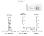
- FIGS. 8 and 9 are graphs showing aberration characteristics according to the third preferred embodiment of the present invention.
- the aberration characteristics are shown by representing a plurality of wavelengths by a plurality of colors.
- FIG. 8 is a graph obtained by measuring longitudinal spherical aberration, astigmatic field curve, and distortion according to the third preferred embodiment ofthe present invention.
- FIG. 9 is a graph obtained by measuring coma aberration according to the third preferred embodiment of the present invention.
- the graph obtained by measuring the longitudinal spherical aberration shows longitudinal spherical aberration depending on each wavelength.
- each wavelength is adjacent to a vertical axis, characteristics of the longitudinal spherical aberration are excellent.
- the graph obtained by measuring the astigmatic field curve shows aberration characteristics of a direction component (X) of x axis light and a direction component (Y) of y axis light according to an image surface height (ANGLE) viewed from the object side, which is a vertical axis, and a focus (FOCUS) position, which is a horizontal axis.
- ANGLE image surface height
- FOCUS focus
- the graph obtained by measuring the distortion shows distortion characteristics, which are a horizontal axis, according to an image surface height (ANGLE) viewed from the object side.
- ANGLE image surface height
- the graph obtained by measuring the coma aberration shows tangential and sagittal aberration characteristics depending on each wavelength according to an image surface height.
- each wave length is adjacent to a horizontal axis, small transversal chromatic aberration appears.
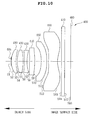
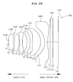
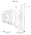
- FIG. 10 is a lateral cross-sectional view schematically showing an internal structure of an imaging lens according to a fourth preferred embodiment of the present invention.
- the imaging lens 400 according to the fourth preferred embodiment of the present invention is configured to include a first lens 410, a second lens 420, a third lens 430, a fourth lens 440, a fifth lens 450, and a sixth lens 460 sequentially disposed from an object side.
- the imaging lens 400 according to the fourth preferred embodiment of the present invention may further include an aperture stop 405 positioned to be closer to the object side or an image surface side as compared with any one of the first to sixth lenses 410 and 460.
- light corresponding to image information of the object sequentially passes through the first lens 410, the aperture stop 405, the second lens 420, the third lens 430, the fourth lens 440, the fifth lens 450, the sixth lens 460, and a filter 470, and is then incident to a light receiving element 480.
- the first lens 410 is formed to have positive (+) power and have a shape in which it is convex toward the object side.
- the second lens 420 is formed to have positive (+) power.
- the third and fourth lenses 430 and 440 may be formed to positive (+) or negative (-) power.
- At least one ofthe third and fourth lenses 430 and 440 is formed to have the Abbe number (V) smaller than 30, thereby making it possible to significantly decrease chromatic aberration.
- the present invention is not necessary limited thereto.
- at least one ofthe third and fourth lenses 430 and 440 is formed to have the Abbe number (V) that is in the range of 20 to 30, thereby making it possible to more significantly decrease chromatic aberration.
- the fifth lens 450 may be formed to have positive (+) power and have a shape in which it is concave toward the object side and is convex the image surface side.
- the fifth lens 450 is formed to have a point of inflection on at least one of a surface thereof toward the object side and a surface thereoftoward the image surface side.
- the sixth lens 460 is formed to have negative (-) power, be concave toward the image surface side, and have a point of inflection on a surface thereoftoward the image surface side.
- the first lens 410, the second lens 420, the third lens 430, the fourth lens 440, the fifth lens 450, and the sixth lens 460 may be formed as an aspheric surface.
- the present invention is not limited thereto.
- the aperture stop 405 is disposed to be closer to the object side or the image surface side as compared with any one of the first to fifth lenses 410 and 450 and selectively collects incident light to adjust a focal length.
- the aperture stop 405 may be disposed to be closer to the object side or the image surface side as compared with the first lens 410.
- the aperture stop 405 may be disposed between a surface of the first lens 410 toward the object side and a surface of the third lens 430 toward the object side.
- a position ofthe aperture stop 405 according to the fourth preferred embodiment of the present invention is not limited to the positions according to an example and another example.
- the filter 470 may be an infrared (IR) cut filter.
- IR infrared
- a kind of filter 470 according to the fourth preferred embodiment ofthe present invention is not limited thereto.
- the IR cut filter serves to cut radiant heat discharged from external light so as not to be transferred to the light receiving element 480.
- the IR cut filter has a structure in which it transmits a visible ray therethrough and reflects an infrared ray to discharge the infrared ray to the outside.
- the light receiving element 480 having a surface on which an image is formed may be configured of an image sensor converting an optical signal corresponding to a subject image into an electrical signal.
- the image sensor may be a charge coupled device (CCD) or a complementary metal oxide semiconductor (CMOS) sensor.
- CMOS complementary metal oxide semiconductor
- the light receiving element according to the preferred embodiment of the present invention is not limited thereto.
- the imaging lens 400 has optical characteristics as shown in the following Table 10.
- Table 10 Lens surface No. Radius of curvature (mm) Thickness (mm) Refractive index Abbe number Lens shape Remark S1 infinite 0 - - Flat Stop S2 1.647 0.356 1.544 56.1 Asphere L1 S3 3.020 0.104 Asphere S4 2.721 0.477 1.544 56.1 Asphere L2 S5 -5.437 0.089 Asphere S6 -5.549 0.205 1.640 23.3 Asphere L3 S7 3.552 0.225 Asphere S8 15.136 0.428 1.640 23.3 Asphere L4 S9 -5.886 0.491 Asphere S10 -2.328 0.442 1.640 23.3 Asphere L5 S11 -2.275 0.149 Asphere S12 8.035 0.712 1.534 55.7 Asphere L6 S13 1.572 0.174 Asphere S14 infinite 0.270 1.517 64.2 Flat Filter S15 infinite 0.580 Flat S16 infinite - - - Flat Image sensor
- all surfaces of the first lens 410 (L1), the second lens 420 (L2), the third lens 430 (L3), the fourth lens 440 (L4), the fifth lens 450 (L5), and the sixth lens 460 (L6) of the imaging lens 400 according to the fourth preferred embodiment of the present invention are aspheric surfaces.
- S1 means a surface determining a light amount of the imaging lens 400 according to the preferred embodiment of the present invention
- Stop stated in the Remark column of S1 means the aperture stop 405 (S1) used to adjust a light amount.
- the aperture stop 405 is disposed on the surface of the first lens 410 toward the object side, a position of the aperture stop 405 according to the fourth preferred embodiment of the present invention is not limited thereto.
- the imaging lens 400 according to the fourth preferred embodiment of the present invention is not necessarily limited to including the aperture stop 405.
- Table 11 shows aspheric constant values of aspheric lenses according to the fourth preferred embodiment of the present invention.
- S1 which is the aperture stop 405 (S1) used to adjust the light amount, is flat, such that it does not have an aspheric constant value.
- S14 and S15 which are the filter 470
- S16 which is the image sensor corresponding to the light receiving element 480
- S14 and S15 are flat, such that they do not have aspheric constant values.
- the entire focal length of the imaging lens 400 according to the fourth preferred embodiment of the present invention is F and focal lengths of the first lens 410, the second lens 420, the third lens 430, the fourth lens 440, the fifth lens 450, and the sixth lens 460 are F1, F2, F3, F4, F5, and F6, respectively, the respective values are represented by the following Table 12.
- the imaging lens 400 when it is assumed that a length from an incident surface of the first lens 410 toward the object side to the image surface is TTL and the entire focal length ofthe imaging lens 400 is F, the following Conditional Equation maybe satisfied. 0.95 ⁇ TTL / F ⁇ 1.35
- the above Conditional Equation (1) is a relationship equation of TTL and power of the imaging lens 400 according to the fourth preferred embodiment of the present invention.
- the above Conditional Equation (1) is satisfied, thereby making it possible to form the imaging lens 400 in which a telephoto form is possible.
- the above Conditional Equation (3) is a relationship equation of power of the first and second lenses 410 and 420 according to the fourth preferred embodiment of the present invention.
- the imaging lens 400 is designed to have a value smaller or larger than the above Conditional Equation (3), axial performance is deteriorated, such that marketability is deteriorated and it is difficult to secure optical performance.
- the imaging lens 400 when it is assumed that a synthetic focal length of the third and fourth lenses 430 and 440 is F34 and the entire focal length of the imaging lens 400 is F, the following Conditional Equation may be satisfied. - 2.5 ⁇ F / F ⁇ 34 ⁇ - 0.4
- the above Conditional Equation (4) is a relationship equation of power of the third and fourth lenses 430 and 440 according to the fourth preferred embodiment ofthe present invention.
- the imaging lens 400 is designed to have a value smaller or larger than the above Conditional Equation (4), chromatic aberration and off-axis aberration are not appropriately corrected, such that marketability is deteriorated and it is difficult to secure optical performance.
- the imaging lens 400 when it is assumed that a focal length of the first lens 410 is F1 and the entire focal length ofthe imaging lens 400 is F, the following Conditional Equation may be satisfied. 0 ⁇ F / F ⁇ 1 ⁇ 1.5
- the above Conditional Equation (5) is a relationship equation of power of the first lens 410 according to the fourth preferred embodiment of the present invention.
- a optical power is decreased, such that sensitivity is decreased.
- the imaging lens 400 when it is assumed that a focal length of the third lens 430 is F3 and the entire focal length ofthe imaging lens 400 is F, the following Conditional Equation may be satisfied. 0.2 ⁇ F / F ⁇ 3 ⁇ 2.5
- the above Conditional Equation (6) is a relationship equation of power of the third lens 430 according to the fourth preferred embodiment of the present invention.
- the imaging lens 400 is designed to have a value smaller or larger than the above Conditional Equation (6), a optical power is dispersed, such that sensitivity is decreased.
- the imaging lens 400 when it is assumed that a focal length ofthe fifth lens 450 is F5, a focal length of the sixth lens 460 is F6, and the entire focal length of the imaging lens 400 is F, the following Conditional Equation may be satisfied. 0.3 ⁇ F / F ⁇ 5 + F / F ⁇ 6 ⁇ 6.0
- the above Conditional Equation (7) is a relationship equation of power of the fifth and sixth lenses 450 and 460 according to the fourth preferred embodiment ofthe present invention.
- the above Conditional Equation (7) is satisfied, thereby making it possible to form the imaging lens 400 in which a telephoto form is possible.
- the imaging lens 400 when it is assumed that a length from an incident surface ofthe first lens 410 toward the object side to the image surface is TTL and an image height is ImgH, the following Conditional Equation may be satisfied. 0.35 ⁇ TTL / 2 ⁇ ImgH ⁇ 0.95
- the above Conditional Equation (8) is a relationship equation of TTL and power of the imaging lens 400 according to the fourth preferred embodiment of the present invention.
- the above Conditional Equation (8) is satisfied, thereby making it possible to form the imaging lens 400 in a slim form.
- the above Conditional Equation (9) is a relationship equation for the field of view of the imaging lens 400 according to the fourth preferred embodiment of the present invention.
- the above Conditional Equation (9) is satisfied, thereby making it possible to form the imaging lens 400 in a slim form and a pseudo-wide angle form.
- the above Conditional Equation (10) is a relationship equation for dispersion of the first and second lenses 410 and 420 and the third and fourth lenses 430 and 440 according to the fourth preferred embodiment of the present invention.
- the above Conditional Equation (10) is satisfied, thereby making it possible to effectively decrease chromatic aberration.
- the imaging lens 400 when it is assumed that a focal length ofthe third lens 430 is F3, a focal length ofthe fourth lens 440 is F4, and the entire focal length ofthe imaging lens 400 is F, the following Conditional Equation may be satisfied. 0 ⁇ F / F ⁇ 3 + F / F ⁇ 4 ⁇ 3
- the above Conditional Equation (11) is a relationship equation for optical powers ofthe third and fourth lenses 430 and 440 according to the fourth preferred embodiment of the present invention.
- the above Conditional Equation (11) is satisfied, thereby making it possible to decrease aberration.
- the imaging lens 400 when it is assumed that a radius of curvature of a surface of the first lens 410 toward the image surface side is r12 and the entire focal length ofthe imaging lens 400 is F, the following Conditional Equation may be satisfied. 0.15 ⁇ r ⁇ 12 / F ⁇ 0.9
- the above Conditional Equation (12) is a relationship equation of power for the radius of curvature of the surface of the first lens 410 according to the fourth preferred embodiment of the present invention toward the image surface side.
- the above Conditional Equation (12) is satisfied, thereby making it possible to form the imaging lens 400 having excellent optical characteristics.
- the imaging lens 400 when it is assumed that a focal length of the first lens 410 is F1 and a focal length ofthe third lens 430 is F3, the following Conditional Equation maybe satisfied. 0 ⁇ F ⁇ 1 / F ⁇ 3 ⁇ 25
- the above Conditional Equation (13) is a relationship equation of power of the first and third lenses 410 and 430 according to the fourth preferred embodiment of the present invention.
- the above Conditional Equation (13) is satisfied, thereby making it possible to form the imaging lens 400 having excellent optical characteristics.
- the imaging lens 400 when it is assumed that a radius of curvature of a surface of the fifth lens 450 toward the object side is r9 and a radius of curvature of a surface ofthe fifth lens 450 toward the image surface side is r10, the following Conditional Equation may be satisfied. 0 ⁇ r ⁇ 9 - r ⁇ 10 / r ⁇ 9 + r ⁇ 10 ⁇ 6
- the above Conditional Equation (14) is a relationship equation ofpower ofthe fifth lens 450 according to the fourth preferred embodiment of the present invention.
- the above Conditional Equation (14) is satisfied, thereby making it possible to form the fifth lens 450 having the positive (+) power.
- the imaging lens 400 when it is assumed that the entire focal length of the imaging lens 400 is F, a focal length of the first lens 410 is F1, and a focal length of the second lens 420 is F2, the following Conditional Equation may be satisfied. 0.2 ⁇ F / F ⁇ 1 + F / F ⁇ 2 ⁇ 4
- the above Conditional Equation (15) is a relationship equation for determining the entire power of the imaging lens 400 according to the fourth preferred embodiment of the present invention.
- the above Conditional Equation (15) is satisfied, thereby making it possible to form the imaging lens 400 having excellent optical characteristics.
- a focal length of the first lens 410 is F1
- a focal length of the second lens 420 is F2
- a focal length of the third lens 430 is F3
- a focal length of the fourth lens 440 is F4
- the above Conditional Equation (16) is a relationship equation of power of the first lens 410, the second lens 420, the third lens 430, and the fourth lens 440 according to the fourth preferred embodiment of the present invention.
- the above Conditional Equation (16) is satisfied, thereby making it possible to form the imaging lens 400 having excellent optical characteristics.
- a focal length of the fourth lens 440 is F4
- a focal length of the fifth lens 450 is F5
- a focal length of the sixth lens 460 is F6
- the following Conditional Equation may be satisfied. 0.20 ⁇ F / F ⁇ 4 + F / F ⁇ 5 + F / F ⁇ 6 ⁇ 7.5
- the above Conditional Equation (17) is a relationship equation of power of the fourth lens 440, the fifth lens 450, and the sixth lens 460 according to the fourth preferred embodiment of the present invention.
- the above Conditional Equation (17) is satisfied, thereby making it possible to form the imaging lens 400 having excellent optical characteristics.
- the imaging lens 400 when it is assumed that the entire focal length ofthe imaging lens 400 is F and a length between a surface of the first lens 410 toward the object side and a surface of the sixth surface 460 toward the image surface side on an optical axis is DL, the following Conditional Equation may be satisfied. 0.7 ⁇ DL / F ⁇ 1.2
- the imaging lens 400 when it is assumed that the Abbe number of the fourth lens 440 is v4 and the Abbe number ofthe fifth lens 450 is v5, the following Conditional Equation may be satisfied. 42 ⁇ v ⁇ 4 + v ⁇ 5 ⁇ 115
- the above Conditional Equation (19) is a relationship equation for dispersion of the fourth and fifth lenses 440 and 450 according to the fourth preferred embodiment of the present invention.
- the above Conditional Equation (19) is satisfied, thereby making it possible to form the imaging lens 400 having excellent optical characteristics.
- FIGS. 11 and 12 are graphs showing aberration characteristics according to the fourth preferred embodiment ofthe present invention.
- the aberration characteristics are shown by representing a plurality of wavelengths by a plurality of colors.
- FIG. 11 is a graph obtained by measuring longitudinal spherical aberration, astigmatic field curve, and distortion according to the fourth preferred embodiment of the present invention.
- FIG. 12 is a graph obtained by measuring coma aberration according to the fourth preferred embodiment ofthe present invention.
- the graph obtained by measuring the longitudinal spherical aberration shows longitudinal spherical aberration depending on each wavelength.
- each wavelength is adjacent to a vertical axis, characteristics of the longitudinal spherical aberration are excellent.
- the graph obtained by measuring the astigmatic field curve shows aberration characteristics of a direction component (X) of x axis light and a direction component (Y) of y axis light according to an image surface height (ANGLE) viewed from the object side, which is a vertical axis, and a focus (FOCUS) position, which is a horizontal axis.
- ANGLE image surface height
- FOCUS focus
- the graph obtained by measuring the distortion shows distortion characteristics, which are a horizontal axis, according to an image surface height (ANGLE) viewed from the object side.
- ANGLE image surface height
- the graph obtained by measuring the coma aberration shows tangential and sagittal aberration characteristics depending on each wavelength according to an image surface height.
- the graph obtained by measuring the coma aberration shows tangential and sagittal aberration characteristics depending on each wavelength according to an image surface height.
- FIG. 13 is a lateral cross-sectional view schematically showing an internal structure of an imaging lens according to a fifth preferred embodiment ofthe present invention.
- the imaging lens 500 is configured to include a first lens 510, a second lens 520, a third lens 530, a fourth lens 540, a fifth lens 550, and a sixth lens 560 sequentially disposed from an object side.
- the imaging lens 500 according to the fifth preferred embodiment ofthe present invention may further include an aperture stop 505 positioned to be closer to the object side or an image surface side as compared with any one ofthe first to sixth lenses 510 and 560.
- light corresponding to image information of the object sequentially passes through the first lens 510, the aperture stop 505, the second lens 520, the third lens 530, the fourth lens 540, the fifth lens 550, the sixth lens 560, and a filter 570, and is then incident to a light receiving element 580.
- the first lens 510 is formed to have positive (+) power and have a shape in which it is convex toward the object side.
- the second lens 520 is formed to have positive (+) power.
- the third and fourth lenses 530 and 540 may be formed to positive (+) or negative (-) power.
- At least one ofthe third and fourth lenses 530 and 540 is formed to have the Abbe number (V) smaller than 30, thereby making it possible to significantly decrease chromatic aberration.
- the present invention is not necessary limited thereto.
- at least one ofthe third and fourth lenses 530 and 540 is formed to have the Abbe number (V) that is in the range of 20 to 30, thereby making it possible to more significantly decrease chromatic aberration.
- the fifth lens 550 may be formed to have negative (-) power and have a shape in which it is concave toward the object side.
- the fifth lens 550 may be formed to have a point of inflection on at least one of a surface thereof toward the object side and a surface thereoftoward the image surface side.
- the sixth lens 560 is formed to have negative (-) power, be concave toward the image surface side, and have a point of inflection on a surface thereoftoward the image surface side.
- the first lens 510, the second lens 520, the third lens 530, the fourth lens 540, the fifth lens 550, and the sixth lens 560 may be formed as an aspheric surface.
- the present invention is not limited thereto.
- the aperture stop 505 is disposed to be closer to the object side or the image surface side as compared with any one of the first to fifth lenses 510 and 550 and selectively collects incident light to adjust a focal length.
- the aperture stop 505 may be disposed to be closer to the object side or the image surface side as compared with the first lens 510.
- the aperture stop 505 may be disposed between a surface of the first lens 510 toward the object side and a surface of the third lens 530 toward the object side.
- a position ofthe aperture stop 505 according to the fifth preferred embodiment of the present invention is not limited to the positions according to an example and another example.
- the filter 570 may be an infrared (IR) cut filter.
- IR infrared
- a kind of filter 570 according to the fifth preferred embodiment ofthe present invention is not limited thereto.
- the IR cut filter serves to cut radiant heat discharged from external light so as not to be transferred to the light receiving element 580.
- the IR cut filter has a structure in which it transmits a visible ray therethrough and reflects an infrared ray to discharge the infrared ray to the outside.
- the light receiving element 580 having a surface on which an image is formed may be configured of an image sensor converting an optical signal corresponding to a subject image into an electrical signal.
- the image sensor may be a charge coupled device (CCD) or a complementary metal oxide semiconductor (CMOS) sensor.
- CMOS complementary metal oxide semiconductor
- the light receiving element according to the preferred embodiment of the present invention is not limited thereto.
- the imaging lens 500 has optical characteristics as shown in the following Table 13.
- Table 13 Lens surface No. Radius of curvature (mm) Thickness (mm) Refractive index Abbe number Lens shape Remark S1 infinite 0 - - Flat Stop S2 1.648 0.377 1.5441 56.1 Asphere L1 S3 3.662 0.093 Asphere S4 3.309 0.458 1.5441 56.1 Asphere L2 S5 -5.055 0.080 Asphere S6 -5.260 0.205 1.6398 23.3 Asphere L3 S7 3.603 0.223 Asphere S8 15.574 0.429 1.6398 23.3 Asphere L4 S9 -5.840 0.446 Asphere S10 -2.448 0.346 1.6398 23.3 Asphere L5 S11 -2.685 0.194 Asphere S12 7.975 0.840 1.5343 55.7 Asphere L6 S13 1.775 0.161 Asphere S14 infinite 0.270 1.5168 64.2 Flat Filter S15 infinite 0.580 Flat S16
- all surfaces ofthe first lens 510 (L1), the second lens 520 (L2), the third lens 530 (L3), the fourth lens 540 (L4), the fifth lens 550 (L5), and the sixth lens 560 (L6) of the imaging lens 500 according to the fifth preferred embodiment ofthe present invention are aspheric surfaces.
- S1 means a surface determining a light amount of the imaging lens 500 according to the preferred embodiment of the present invention
- Stop stated in the Remark column of S1 means the aperture stop 505 (S1) used to adjust a light amount.
- the aperture stop 505 is disposed on the surface of the first lens 510 toward the object side, a position of the aperture stop 505 according to the fifth preferred embodiment of the present invention is not limited thereto.
- the imaging lens 500 according to the fifth preferred embodiment of the present invention is not necessarily limited to including the aperture stop 505.
- Table 14 shows aspheric constant values of aspheric lenses according to the fifth preferred embodiment of the present invention.
- S1 which is the aperture stop 505 (S1) used to adjust the light amount, is flat, such that it does not have an aspheric constant value.
- S14 and S15 which are the filter 570, and S16, which is the image sensor corresponding to the light receiving element 580, are flat, such that they do not have aspheric constant values.
- the entire focal length of the imaging lens 500 according to the fifth preferred embodiment ofthe present invention is F and focal lengths ofthe first lens 510, the second lens 520, the third lens 530, the fourth lens 540, the fifth lens 550, and the sixth lens 560 are F1, F2, F3, F4, F5, and F6, respectively, the respective values are represented by the following Table 15.
- the imaging lens 500 when it is assumed that a length from an incident surface of the first lens 510 toward the object side to the image surface is TTL and the entire focal length of the imaging lens 500 is F, the following Conditional Equation may be satisfied. 0.95 ⁇ TTL / F ⁇ 1.35
- the above Conditional Equation (1) is a relationship equation of TTL and power of the imaging lens 500 according to the fifth preferred embodiment of the present invention.
- the above Conditional Equation (1) is satisfied, thereby making it possible to form the imaging lens 500 in which a telephoto form is possible.
- the above Conditional Equation (3) is a relationship equation of power of the first and second lenses 510 and 520 according to the fifth preferred embodiment of the present invention.
- the imaging lens 500 is designed to have a value smaller or larger than the above Conditional Equation (3), axial performance is deteriorated, such that marketability is deteriorated and it is difficult to secure optical performance.
- the imaging lens 500 when it is assumed that a synthetic focal length of the third and fourth lenses 530 and 540 is F34 and the entire focal length of the imaging lens 500 is F, the following
- the above Conditional Equation (4) is a relationship equation of power of the third and fourth lenses 530 and 540 according to the fourth preferred embodiment ofthe present invention.
- the imaging lens 500 is designed to have a value smaller or larger than the above Conditional Equation (4), chromatic aberration and off-axis aberration are not appropriately corrected, such that marketability is deteriorated and it is difficult to secure optical performance.
- the imaging lens 500 when it is assumed that a focal length ofthe first lens 510 is F1 and the entire focal length ofthe imaging lens 500 is F, the following Conditional Equation may be satisfied. 0 ⁇ F / F ⁇ 1 ⁇ 1.5
- the above Conditional Equation (5) is a relationship equation of power of the first lens 510 according to the fifth preferred embodiment ofthe present invention.
- the imaging lens 500 is designed to have a value smaller or larger than the above Conditional Equation (5), a optical power is decreased, such that sensitivity is decreased.
- the imaging lens 500 when it is assumed that a focal length of the third lens 530 is F3 and the entire focal length ofthe imaging lens 500 is F, the following Conditional Equation may be satisfied. 0.2 ⁇ F / F ⁇ 3 ⁇ 2.5
- the above Conditional Equation (6) is a relationship equation of power of the third lens 530 according to the fifth preferred embodiment ofthe present invention.
- the imaging lens 500 is designed to have a value smaller or larger than the above Conditional Equation (6), a optical power is dispersed, such that sensitivity is decreased.
- the imaging lens 500 when it is assumed that a focal length ofthe fifth lens 550 is F5, a focal length ofthe sixth lens 560 is F6, and the entire focal length of the imaging lens 500 is F, the following Conditional Equation may be satisfied. 0.3 ⁇ F / F ⁇ 5 + F / F ⁇ 6 ⁇ 6.0
- the above Conditional Equation (7) is a relationship equation of power of the fifth and sixth lenses 550 and 560 according to the fifth preferred embodiment of the present invention.
- the above Conditional Equation (7) is satisfied, thereby making it possible to form the imaging lens 500 in which a telephoto form is possible.
- the imaging lens 500 when it is assumed that a length from an incident surface of the first lens 510 toward the object side to the image surface is TTL and an image height is ImgH, the following Conditional Equation may be satisfied. 0.35 ⁇ TTL / 2 ⁇ ImgH ⁇ 0.95
- the above Conditional Equation (8) is a relationship equation of TTL and power of the imaging lens 500 according to the fifth preferred embodiment of the present invention.
- the above Conditional Equation (8) is satisfied, thereby making it possible to form the imaging lens 500 in a slim form.
- the above Conditional Equation (9) is a relationship equation for the field of view of the imaging lens 500 according to the fifth preferred embodiment of the present invention.
- the above Conditional Equation (9) is satisfied, thereby making it possible to form the imaging lens 500 in a slim form and a pseudo-wide angle form.
- the imaging lens 500 when it is assumed that an average of the Abbe numbers of the first and second lenses 510 and 520 is v12 and an average of the Abbe numbers of the third and fourth lenses 530 and 540 is v34, the following Conditional Equation may be satisfied. 10 ⁇ v ⁇ 12 - v ⁇ 34 ⁇ 45
- the above Conditional Equation (10) is a relationship equation for dispersion of the first and second lenses 510 and 520 and the third and fourth lenses 530 and 540 according to the fifth preferred embodiment of the present invention.
- the above Conditional Equation (10) is satisfied, thereby making it possible to effectively decrease chromatic aberration.
- the imaging lens 500 when it is assumed that a focal length of the third lens 530 is F3, a focal length of the fourth lens 540 is F4, and the entire focal length of the imaging lens 500 is F, the following Conditional Equation may be satisfied. 0 ⁇ F / F ⁇ 3 + F / F ⁇ 4 ⁇ 3
- the above Conditional Equation (11) is a relationship equation for optical powers ofthe third and fourth lenses 530 and 540 according to the fifth preferred embodiment of the present invention.
- the above Conditional Equation (11) is satisfied, thereby making it possible to decrease aberration.
- the imaging lens 500 when it is assumed that a radius of curvature of a surface of the first lens 510 toward the image surface side is r12 and the entire focal length of the imaging lens 500 is F, the following Conditional Equation may be satisfied. 0.15 ⁇ r ⁇ 12 / F ⁇ 0.9
- the above Conditional Equation (12) is a relationship equation of power for the radius of curvature of the surface of the first lens 510 according to the fifth preferred embodiment of the present invention toward the image surface side.
- the above Conditional Equation (12) is satisfied, thereby making it possible to form the imaging lens 500 having excellent optical characteristics.
- the imaging lens 500 when it is assumed that a focal length of the first lens 510 is F1 and a focal length ofthe third lens 530 is F3, the following Conditional Equation may be satisfied. 0 ⁇ F ⁇ 1 / F ⁇ 3 ⁇ 25
- the above Conditional Equation (13) is a relationship equation of power of the first and third lenses 510 and 530 according to the fifth preferred embodiment of the present invention.
- the above Conditional Equation (13) is satisfied, thereby making it possible to form the imaging lens 500 having excellent optical characteristics.
- the imaging lens 500 when it is assumed that a radius of curvature of a surface ofthe fifth lens 550 toward the object side is r9 and a radius of curvature of a surface ofthe fifth lens 550 toward the image surface side is r10, the following Conditional Equation may be satisfied. 0 ⁇ r ⁇ 9 - r ⁇ 10 / r ⁇ 9 + r ⁇ 10 ⁇ 6
- the above Conditional Equation (14) is a relationship equation ofpower ofthe fifth lens 550 according to the fifth preferred embodiment ofthe present invention.
- the above Conditional Equation (14) is satisfied, thereby making it possible to form the fifth lens 550 having the positive (+) power.
- the imaging lens 500 when it is assumed that the entire focal length of the imaging lens 500 is F, a focal length of the first lens 510 is F1, and a focal length of the second lens 520 is F2, the following Conditional Equation may be satisfied. 0.2 ⁇ F / F ⁇ 1 + F / F ⁇ 2 ⁇ 4
- the above Conditional Equation (15) is a relationship equation for determining the entire power of the imaging lens 500 according to the fifth preferred embodiment of the present invention.
- the above Conditional Equation (15) is satisfied, thereby making it possible to form the imaging lens 500 having excellent optical characteristics.
- a focal length of the first lens 510 is F1
- a focal length of the second lens 520 is F2
- a focal length of the third lens 530 is F3
- a focal length of the fourth lens 540 is F4
- the above Conditional Equation (16) is a relationship equation of power of the first lens 510, the second lens 520, the third lens 530, and the fourth lens 540 according to the fifth preferred embodiment of the present invention.
- the above Conditional Equation (16) is satisfied, thereby making it possible to form the imaging lens 500 having excellent optical characteristics.
- a focal length of the fourth lens 540 is F4
- a focal length of the fifth lens 550 is F5
- a focal length ofthe sixth lens 560 is F6
- the following Conditional Equation maybe satisfied. 0.20 ⁇ F / F ⁇ 4 + F / F ⁇ 5 + F / F ⁇ 6 ⁇ 7.5
- the above Conditional Equation (17) is a relationship equation of power of the fourth lens 540, the fifth lens 550, and the sixth lens 560 according to the fifth preferred embodiment of the present invention.
- the above Conditional Equation (17) is satisfied, thereby making it possible to form the imaging lens 500 having excellent optical characteristics.
- the imaging lens 500 when it is assumed that the entire focal length ofthe imaging lens 500 is F and a length between a surface of the first lens 510 toward the object side and a surface of the sixth surface 560 toward the image surface side on an optical axis is DL, the following Conditional Equation may be satisfied. 0.7 ⁇ DL / F ⁇ 1.2
- the imaging lens 500 when it is assumed that the Abbe number of the fourth lens 540 is v4 and the Abbe number ofthe fifth lens 550 is v5, the following Conditional Equation may be satisfied. 42 ⁇ v ⁇ 4 + v ⁇ 5 ⁇ 115
- the above Conditional Equation (19) is a relationship equation for dispersion of the fourth and fifth lenses 540 and 550 according to the fifth preferred embodiment of the present invention.
- the above Conditional Equation (19) is satisfied, thereby making it possible to form the imaging lens 500 having excellent optical characteristics.
- FIGS. 14 and 15 are graphs showing aberration characteristics according to the fifth preferred embodiment ofthe present invention.
- the aberration characteristics are shown by representing a plurality of wavelengths by a plurality of colors.
- FIG. 14 is a graph obtained by measuring longitudinal spherical aberration, astigmatic field curve, and distortion according to the fifth preferred embodiment of the present invention.
- FIG. 15 is a graph obtained by measuring coma aberration according to the fifth preferred embodiment ofthe present invention.
- the graph obtained by measuring the longitudinal spherical aberration shows longitudinal spherical aberration depending on each wavelength.
- each wavelength is adjacent to a vertical axis, characteristics of the longitudinal spherical aberration are excellent.
- the graph obtained by measuring the astigmatic field curve shows aberration characteristics of a direction component (X) of x axis light and a direction component (Y) of y axis light according to an image surface height (ANGLE) viewed from the object side, which is a vertical axis, and a focus (FOCUS) position, which is a horizontal axis.
- ANGLE image surface height
- FOCUS focus
- the graph obtained by measuring the distortion shows distortion characteristics, which are a horizontal axis, according to an image surface height (ANGLE) viewed from the object side.
- ANGLE image surface height
- the graph obtained by measuring the coma aberration shows tangential and sagittal aberration characteristics depending on each wavelength according to an image surface height.
- the graph obtained by measuring the coma aberration shows tangential and sagittal aberration characteristics depending on each wavelength according to an image surface height.
- FIG. 6 is a lateral cross-sectional view schematically showing an internal structure of an imaging lens according to a sixth preferred embodiment of the present invention.
- the imaging lens 600 has optical characteristics as shown in the following Table 16.
- Table 16 Lens surface No. Radius of curvature (mm) Thickness (mm) Refractive index Abbe number Lens shape Remark S1 infinite 0 - - Flat Stop S2 2.524 0.442 1.543 56.1 Asphere L1 S3 5.794 0.158 Asphere S4 4.189 0.538 1.544 56.1 Asphere L2 S5 -4.328 0.070 Asphere S6 -5.028 0.300 1.616 25.2 Asphere L3 S7 6.085 0.586 Asphere S8 -4.288 0.633 1.562 43.1 Asphere L4 S9 -4.308 0.197 Asphere S10 3.766 0.601 1.544 56.1 Asphere L5 S11 -2.290 0.476 Asphere S12 -1.933 0.300 1.541 49.4 Asphere L6 S13 2.776 0.300 Asphere S14 0.000 0.300 1.516 64.2 Flat Filter S15 0.000 0.600 Flat S
- all surfaces ofthe first lens 610 (L1), the second lens 620 (L2), the third lens 630 (L3), the fourth lens 640 (L4), the fifth lens 650 (L5), and the sixth lens 660 (L6) ofthe imaging lens 600 according to the sixth preferred embodiment ofthe present invention are aspheric surfaces.
- S1 means a surface determining a light amount of the imaging lens 600 according to the preferred embodiment of the present invention
- Stop stated in the Remark column of S1 means the aperture stop 605 (S1) used to adjust a light amount.
- the aperture stop 605 is disposed on the surface of the first lens 610 toward the object side, a position of the aperture stop 605 according to the sixth preferred embodiment of the present invention is not limited thereto.
- the imaging lens 600 according to the sixth preferred embodiment of the present invention is not necessarily limited to including the aperture stop 605.
- Table 17 shows aspheric constant values of aspheric lenses according to the sixth preferred embodiment ofthe present invention.
- S1 which is the aperture stop 605 (S1) used to adjust the light amount, is flat, such that it does not have an aspheric constant value.
- S14 and S15 which are the filter 670, and S16, which is the image sensor corresponding to the light receiving element 680, are flat, such that they do not have aspheric constant values.
- FIG. 17 is graphs showing aberration characteristics according to the sixth preferred embodiment of the present invention.
- the aberration characteristics are shown by representing a plurality of wavelengths by a plurality of cobrs.
- FIG. 17 is a graph obtained by measuring longitudinal spherical aberration, astigmatic field curve, and distortion according to the sixth preferred embodiment of the present invention.
- FIG. 18 is a lateral cross-sectional view schematically showing an internal structure of an imaging lens according to a seventh preferred embodiment ofthe present invention.
- the imaging lens 200 has optical characteristics as shown in the following Table 18.
- Table 18 Lens surface No. Radius of curvature (mm) Thickness (mm) Refractive index Abbe number Lens shape Remark S1 infinite 0 - - Flat Stop S2 3.138 0.397 1.544 56.1 Flat L1 S3 22.353 0.142 Asphere S4 6.911 0.622 1.544 56.1 Asphere L2 S5 -3.570 0.322 Asphere S6 -3.004 0.300 1.632 23.4 Asphere L3 S7 7.594 0.150 Asphere S8 22.855 0.650 1.581 33.0 Asphere L4 S9 -13.856 0.227 Asphere S10 3.219 0.804 1.553 48.6 Asphere L5 S11 -2.050 0.386 Asphere S12 -1.720 0.300 1.509 59.1 Asphere L6 S13 2.727 0.300 Asphere S14 infinite 0.300 1.516 64.2 Asphere Filter S15 infinite 0.600 Flat S
- all surfaces ofthe first lens 710 (L1), the second lens 720 (L2), the third lens 730 (L3), the fourth lens 740 (L4), the fifth lens 750 (L5), and the sixth lens 760 (L6) of the imaging lens 700 according to the seventh preferred embodiment of the present invention are aspheric surfaces.
- S1 means a surface determining a light amount of the imaging lens 700 according to the preferred embodiment of the present invention
- Stop stated in the Remark column of S1 means the aperture stop 705 (S1) used to adjust a light amount.
- the aperture stop 705 is disposed on the surface of the first lens 710 toward the object side, a position of the aperture stop 705 according to the seventh preferred embodiment of the present invention is not limited thereto.
- the imaging lens 700 according to the seventh preferred embodiment of the present invention is not necessarily limited to including the aperture stop 705.
- Table 19 shows aspheric constant values of aspheric lenses according to the seventh preferred embodiment ofthe present invention.
- S1 which is the aperture stop 705 (S1) used to adjust the light amount, is flat, such that it does not have an aspheric constant value.
- S14 and S15 which are the filter 770, and S16, which is the image sensor corresponding to the light receiving element 780, are flat, such that they do not have aspheric constant values.
- FIG. 19 is graphs showing aberration characteristics according to the seventh preferred embodiment of the present invention.
- the aberration characteristics are shown by representing a plurality of wavelengths by a plurality of cobrs.
- FIG. 19 is a graph obtained by measuring longitudinal spherical aberration, astigmatic field curve, and distortion according to the seventh preferred embodiment of the present invention.
- FIG. 20 is a lateral cross-sectional view schematically showing an internal structure of an imaging lens according to a eighth preferred embodiment ofthe present invention.
- the imaging lens 800 has optical characteristics as shown in the following Table 20.
- Table 20 Lens surface No. Radius of curvature (mm) Thickness (mm) Refractive index Abbe number Lens shape Remark S1 infinite 0 - - Flat Stop S2 3.331 0.683 1.544 56.1 Asphere L1 S3 1062.253 0.121 Asphere S4 4.049 0.583 1.544 56.1 Asphere L2 S5 -2.988 0.050 Asphere S6 -3.646 0.300 1.623 24.4 Asphere L3 S7 10.421 0.503 Asphere S8 -1.419 0.523 1.612 25.8 Asphere L4 S9 -1.536 0.166 Asphere S10 63.096 0.837 1.544 56.1 Asphere L5 S11 -1.744 0.516 Asphere S12 -1.903 0.300 1.549 47.2 Asphere L6 S13 2.802 0.300 Asphere S14 infinite 0.300 1.516 64.2 Flat Filter S15
- all surfaces of the first lens 810 (L1), the second lens 820 (L2), the third lens 830 (L3), the fourth lens 840 (L4), the fifth lens 850 (L5), and the sixth lens 860 (L6) of the imaging lens 800 according to the eighth preferred embodiment of the present invention are aspheric surfaces.
- S1 means a surface determining a light amount of the imaging lens 800 according to the preferred embodiment of the present invention
- Stop stated in the Remark column of S1 means the aperture stop 805 (S1) used to adjust a light amount.
- the aperture stop 805 is disposed on the surface of the first lens 810 toward the object side, a position of the aperture stop 805 according to the eighth preferred embodiment of the present invention is not limited thereto.
- the imaging lens 800 according to the eighth preferred embodiment of the present invention is not necessarily limited to including the aperture stop 805.
- Table 21 shows aspheric constant values of aspheric lenses according to the eighth preferred embodiment ofthe present invention.
- S1 which is the aperture stop 805 (S1) used to adjust the light amount, is flat, such that it does not have an aspheric constant value.
- S14 and S15 which are the filter 870, and S16, which is the image sensor corresponding to the light receiving element 880, are flat, such that they do not have aspheric constant values.
- FIG. 21 is graphs showing aberration characteristics according to the eighth preferred embodiment of the present invention.
- the aberration characteristics are shown by representing a plurality of wavelengths by a plurality of cobrs.
- FIG. 21 is a graph obtained by measuring longitudinal spherical aberration, astigmatic field curve, and distortion according to the eighth preferred embodiment of the present invention.
- FIG. 22 is a lateral cross-sectional view schematically showing an internal structure of an imaging lens according to a ninth preferred embodiment ofthe present invention.
- the imaging lens 900 has optical characteristics as shown in the following Table 22.
- Table 22 Lens surface No. Radius of curvature (mm) Thickness (mm) Refractive index Abbe number Lens shape Remark S1 infinite 0 - - Flat Stop S2 2.524 0.442 1.543 56.1 Asphere L1 S3 5.794 0.158 Asphere S4 4.189 0.538 1.544 56.1 Asphere L2 S5 -4.328 0.070 Asphere S6 -5.028 0.300 1.616 25.2 Asphere L3 S7 6.085 0.586 Asphere S8 -4.288 0.633 1.562 43.1 Asphere L4 S9 -4.308 0.197 Asphere S10 3.766 0.601 1.544 56.1 Asphere L5 S11 -2.290 0.476 Asphere S12 -1.933 0.300 1.541 49.4 Asphere L6 S13 2.776 0.300 Asphere S14 0.000 0.300 1.516 64.2 Flat Filter S15 0.000 0.600
- all surfaces ofthe first lens 910 (L1), the second lens 920 (L2), the third lens 930 (L3), the fourth lens 940 (L4), the fifth lens 950 (L5), and the sixth lens 960 (L6) of the imaging lens 900 according to the ninth preferred embodiment of the present invention are aspheric surfaces.
- S1 means a surface determining a light amount of the imaging lens 900 according to the preferred embodiment of the present invention
- Stop stated in the Remark column of S1 means the aperture stop 905 (S1) used to adjust a light amount.
- the aperture stop 905 is disposed on the surface of the first lens 910 toward the object side, a position of the aperture stop 905 according to the ninth preferred embodiment of the present invention is not limited thereto.
- the imaging lens 900 according to the ninth preferred embodiment ofthe present invention is not necessarily limited to including the aperture stop 905.
- Table 23 shows aspheric constant values of aspheric lenses according to the ninth preferred embodiment ofthe present invention.
- S1 which is the aperture stop 905 (S1) used to adjust the light amount, is flat, such that it does not have an aspheric constant value.
- S14 and S15 which are the filter 970, and S16, which is the image sensor corresponding to the light receiving element 980, are flat, such that they do not have aspheric constant values.
- FIG. 23 is graphs showing aberration characteristics according to the ninth preferred embodiment of the present invention.
- the aberration characteristics are shown by representing a plurality of wavelengths by a plurality of cobrs.
- FIG. 23 is a graph obtained by measuring longitudinal spherical aberration, astigmatic field curve, and distortion according to the ninth preferred embodiment of the present invention.
- FIG. 24 is a lateral cross-sectional view schematically showing an internal structure of an imaging lens according to a tenth preferred embodiment ofthe present invention.
- the imaging lens 1000 has optical characteristics as shown in the following Table 24.
- Table 24 Lens surface No. Radius of curvature (mm) Thickness (mm) Refractive index Abbe number Lens shape Remark S1 infinite 0 - - Flat Stop S2 7.298 0.300 1.611 27.6 Asphere L1 S3 8.599 0.050 Asphere S4 3.054 0.762 1.544 56.1 Asphere L2 S5 -2.459 0.293 Asphere S6 -2.119 0.300 1.630 23.5 Asphere L3 S7 -17.090 0.381 Asphere S8 -17.285 0.303 1.640 23.3 Asphere L4 S9 -17.793 0.284 Asphere S10 7.126 0.915 1.547 53.1 Asphere L5 S11 -1.786 0.412 Asphere S12 -1.780 0.300 1.512 57.9 Asphere L6 S13 2.904 0.300 Asphere S14 0.000 0.300 1.516 64.2 Flat Filter
- all surfaces ofthe first lens 1010 (L1), the second lens 1020 (L2), the third lens 1030 (L3), the fourth lens 1040 (L4), the fifth lens 1050 (L5), and the sixth lens 1060 (L6) of the imaging lens 1000 according to the tenth preferred embodiment of the present invention are aspheric surfaces.
- S1 means a surface determining a light amount of the imaging lens 1000 according to the preferred embodiment of the present invention
- Stop stated in the Remark column of S1 means the aperture stop 1005 (S1) used to adjust a light amount.
- the aperture stop 1005 is disposed on the surface of the first lens 1010 toward the object side, a position of the aperture stop 1005 according to the tenth preferred embodiment of the present invention is not limited thereto.
- the imaging lens 1000 according to the tenth preferred embodiment ofthe present invention is not necessarily limited to including the aperture stop 1005.
- Table 25 shows aspheric constant values of aspheric lenses according to the tenth preferred embodiment ofthe present invention.
- S1 which is the aperture stop 1005 (S1) used to adjust the light amount, is flat, such that it does not have an aspheric constant value.
- S 14 and S 15, which are the filter 1070, and S16, which is the image sensor corresponding to the light receiving element 1080, are flat, such that they do not have aspheric constant values.
- FIG. 25 is graphs showing aberration characteristics according to the tenth preferred embodiment of the present invention.
- the aberration characteristics are shown by representing a plurality of wavelengths by a plurality of cobrs.
- FIG. 25 is a graph obtained by measuring longitudinal spherical aberration, astigmatic field curve, and distortion according to the tenth preferred embodiment of the present invention.
- FIG. 26 is a lateral cross-sectional view schematically showing an internal structure of an imaging lens according to a eleventh preferred embodiment ofthe present invention.
- the imaging lens 1100 has optical characteristics as shown in the following Table 26.
- Table 26 Lens surface No. Radius of curvature (mm) Thickness (mm) Refractive index Abbe number Lens shape Remark S1 infinite 0 - - Flat Stop S2 2.973 0.527 1.544 56.1 Asphere L1 S3 9.332 0.130 Asphere S4 6.719 0.542 1.544 56.1 Asphere L2 S5 -2.780 0.050 Asphere S6 -27.423 0.300 1.632 23.4 Asphere L3 S7 3.557 0.511 Asphere S8 -2.283 0.346 1.566 35.7 Asphere L4 S9 -3.757 0.236 Asphere S10 4.702 0.894 1.544 56.1 Asphere L5 S11 -1.727 0.463 Asphere S12 -1.783 0.300 1.514 57.1 Asphere L6 S13 2.788 0.300 Asphere S14 0.000 0.300 1.516 64.2 Flat Filter S
- all surfaces ofthe first lens 1110 (L1), the second lens 1120 (L2), the third lens 1130 (L3), the fourth lens 1140 (L4), the fifth lens 1150 (L5), and the sixth lens 1160 (L6) ofthe imaging lens 1100 according to the eleventh preferred embodiment of the present invention are aspheric surfaces.
- S1 means a surface determining a light amount of the imaging lens 1100 according to the preferred embodiment of the present invention
- Stop stated in the Remark column of S1 means the aperture stop 1105 (S 1) used to adjust a light amount.
- the aperture stop 1105 is disposed on the surface of the first lens 1110 toward the object side, a position of the aperture stop 1105 according to the eleventh preferred embodiment of the present invention is not limited thereto.
- the imaging lens 1100 according to the eleventh preferred embodiment of the present invention is not necessarily limited to including the aperture stop 1105.
- Table 27 shows aspheric constant values of aspheric lenses according to the eleventh preferred embodiment ofthe present invention.
- S1 which is the aperture stop 1105 (S1) used to adjust the light amount, is flat, such that it does not have an aspheric constant value.
- S 14 and S 15, which are the filter 1170, and S16, which is the image sensor corresponding to the light receiving element 1180, are flat, such that they do not have aspheric constant values.
- FIG. 27 is graphs showing aberration characteristics according to the eleventh preferred embodiment of the present invention.
- the aberration characteristics are shown by representing a plurality of wavelengths by a plurality of colors.
- FIG. 27 is a graph obtained by measuring longitudinal spherical aberration, astigmatic field curve, and distortion according to the eleventh preferred embodiment of the present invention.
- FIG. 28 is a lateral cross-sectional view schematically showing an internal structure of an imaging lens according to a twelfth preferred embodiment ofthe present invention.
- the imaging lens 1200 has optical characteristics as shown in the following Table 28.
- Table 28 Lens surface No. Radius of curvature (mm) Thickness (mm) Refractive index Abbe number Lens shape Remark S1 infinite 0 - - Flat Stop S2 5.427 0.347 1.549 51.5 Asphere L1 S3 -68.568 0.050 Asphere S4 5.313 0.657 1.544 56.1 Asphere L2 S5 -2.910 0.114 Asphere S6 -29.572 0.475 1.622 24.6 Asphere L3 S7 2.811 0.504 Asphere S8 -4.759 0.547 1.562 43.1 Asphere L4 S9 -6.888 0.135 Asphere S10 4.476 0.802 1.544 56.1 Asphere L5 S11 -1.734 0.369 Asphere S12 -1.678 0.300 1.516 56.5 Asphere L6 S13 2.752 0.300 Asphere S14 0.000 0.300 1.516 64.2 Flat
- all surfaces ofthe first lens 1210 (L1), the second lens 1220 (L2), the third lens 1230 (L3), the fourth lens 1240 (L4), the fifth lens 1250 (L5), and the sixth lens 1260 (L6) of the imaging lens 1200 according to the twelfth preferred embodiment of the present invention are aspheric surfaces.
- S1 means a surface determining a light amount of the imaging lens 1200 according to the preferred embodiment of the present invention
- Stop stated in the Remark column of S1 means the aperture stop 1205 (S1) used to adjust a light amount.
- the aperture stop 1205 is disposed on the surface of the first lens 1210 toward the object side, a position of the aperture stop 1205 according to the twelfth preferred embodiment of the present invention is not limited thereto.
- the imaging lens 1200 according to the twelfth preferred embodiment of the present invention is not necessarily limited to including the aperture stop 1205.
- Table 29 shows aspheric constant values of aspheric lenses according to the twelfth preferred embodiment ofthe present invention.
- S1 which is the aperture stop 1205 (S1) used to adjust the light amount, is flat, such that it does not have an aspheric constant value.
- S 14 and S 15, which are the filter 1270, and S 16, which is the image sensor corresponding to the light receiving element 1280, are flat, such that they do not have aspheric constant values.
- FIG. 29 is graphs showing aberration characteristics according to the twelfth preferred embodiment of the present invention.
- the aberration characteristics are shown by representing a plurality of wavelengths by a plurality of cobrs.
- FIG. 29 is a graph obtained by measuring longitudinal spherical aberration, astigmatic field curve, and distortion according to the twelfth preferred embodiment of the present invention.
- FIG. 30 is a lateral cross-sectional view schematically showing an internal structure of an imaging lens according to a thirteenth preferred embodiment ofthe present invention.
- the imaging lens 1300 has optical characteristics as shown in the following Table 30.
- Table 30 Lens surface No. Radius of curvature (mm) Thickness (mm) Refractive index Abbe number Lens shape Remark S1 infinite 0 - - Flat Stop S2 2.373 0.431 1.544 56.1 Flat L1 S3 5.456 0.151 Asphere S4 3.291 0.435 1.544 56.1 Asphere L2 S5 7.298 0.130 Asphere S6 -11.917 0.486 1.544 56.1 Asphere L3 S7 -1.881 0.153 Asphere S8 -1.322 0.399 1.632 23.4 Asphere L4 S9 -8.220 0.254 Asphere S10 6.739 0.980 1.583 34.3 Asphere L5 S11 -1.743 0.581 Asphere S12 -2.388 0.300 1.555 45.7 Asphere L6 S13 2.818 0.300 Asphere S14 0.000 0.300 1.516 64.2 Asphere Filter S15 -1.743 0.581 Asphere S12 -2.388 0.300 1.555
- all surfaces ofthe first lens 1310 (L1), the second lens 1320 (L2), the third lens 1330 (L3), the fourth lens 1340 (L4), the fifth lens 1350 (L5), and the sixth lens 1360 (L6) of the imaging lens 1300 according to the thirteenth preferred embodiment ofthe present invention are aspheric surfaces.
- S1 means a surface determining a light amount of the imaging lens 1300 according to the preferred embodiment of the present invention
- Stop stated in the Remark column of S1 means the aperture stop 1305 (S1) used to adjust a light amount.
- the aperture stop 1305 is disposed on the surface of the first lens 1310 toward the object side, a position of the aperture stop 1305 according to the thirteenth preferred embodiment of the present invention is not limited thereto.
- the imaging lens 1300 according to the thirteenth preferred embodiment of the present invention is not necessarily limited to including the aperture stop 1305.
- Table 31 shows aspheric constant values of aspheric lenses according to the thirteenth preferred embodiment ofthe present invention.
- S1 which is the aperture stop 1305 (S1) used to adjust the light amount, is flat, such that it does not have an aspheric constant value.
- S 14 and S 15, which are the filter 1370, and S16, which is the image sensor corresponding to the light receiving element 1380, are flat, such that they do not have aspheric constant values.
- FIG. 31 is graphs showing aberration characteristics according to the thirteenth preferred embodiment of the present invention.
- the aberration characteristics are shown by representing a plurality of wavelengths by a plurality of cobrs.
- FIG. 31 is a graph obtained by measuring longitudinal spherical aberration, astigmatic field curve, and distortion according to the thirteenth preferred embodiment of the present invention.
- FIG. 32 is a lateral cross-sectional view schematically showing an internal structure of an imaging lens according to a fourteenth preferred embodiment ofthe present invention.
- the imaging lens 1400 has optical characteristics as shown in the following Table 32.
- Table 32 Lens surface No. Radius of curvature (mm) Thickness (mm) Refractive index Abbe number Lens shape Remark S1 infinite 0 - - Flat Stop S2 3.766 0.442 1.544 56.1 Asphere L1 S3 -8.268 0.050 Asphere S4 6.263 0.340 1.544 56.1 Asphere L2 S5 6.596 0.180 Asphere S6 28.489 0.593 1.544 56.1 Asphere L3 S7 -3.734 0.180 Asphere S8 -1.718 0.324 1.632 23.4 Asphere L4 S9 -10.508 0.242 Asphere S10 9.953 1.002 1.563 42.4 Asphere L5 S11 -1.666 0.647 Asphere S12 -2.366 0.300 1.501 63.0 Asphere L6 S13 2.706 0.300 Asphere S14 0.000 0.300 1.516 64.2 Flat Filter
- all surfaces of the first lens 1410 (L1), the second lens 1420 (L2), the third lens 1430 (L3), the fourth lens 1440 (L4), the fifth lens 1450 (L5), and the sixth lens 1460 (L6) ofthe imaging lens 1400 according to the fourteenth preferred embodiment of the present invention are aspheric surfaces.
- S1 means a surface determining a light amount of the imaging lens 1400 according to the preferred embodiment of the present invention
- Stop stated in the Remark column of S1 means the aperture stop 1405 (S1) used to adjust a light amount.
- the aperture stop 1405 is disposed on the surface of the first lens 1410 toward the object side, a position of the aperture stop 1405 according to the fourteenth preferred embodiment of the present invention is not limited thereto.
- the imaging lens 1400 according to the fourteenth preferred embodiment of the present invention is not necessarily limited to including the aperture stop 1405.
- Table 33 shows aspheric constant values of aspheric lenses according to the fourteenth preferred embodiment ofthe present invention.
- S1 which is the aperture stop 1405 (S1) used to adjust the light amount, is flat, such that it does not have an aspheric constant value.
- S 14 and S 15, which are the filter 1470, and S16, which is the image sensor corresponding to the light receiving element 1480, are flat, such that they do not have aspheric constant values.
- FIG. 33 is graphs showing aberration characteristics according to the fourteenth preferred embodiment of the present invention.
- the aberration characteristics are shown by representing a plurality of wavelengths by a plurality of colors.
- FIG. 33 is a graph obtained by measuring longitudinal spherical aberration, astigmatic field curve, and distortion according to the fourteenth preferred embodiment of the present invention.
- FIG. 34 is a lateral cross-sectional view schematically showing an internal structure of an imaging lens according to a fifteenth preferred embodiment of the present invention.
- the imaging lens 1500 has optical characteristics as shown in the following Table 34.
- Table 34 Lens surface No. Radius of curvature (mm) Thickness (mm) Refractive index Abbe number Lens shape Remark S1 infinite 0 - - Flat Stop S2 1.876 0.531 1.544 56.1 Asphere L1 S3 4.445 0.200 Asphere S4 6.117 0.513 1.544 56.1 Asphere L2 S5 -4.294 0.050 Asphere S6 -12.193 0.300 1.633 23.4 Asphere L3 S7 2.871 0.336 Asphere S8 393.388 0.714 1.573 33.8 Asphere L4 S9 -12.431 0.216 Asphere S10 18.829 0.600 1.551 49.9 Asphere L5 S11 -1.700 0.390 Asphere S12 -1.961 0.450 1.531 54.5 Asphere L6 S13 2.739 0.300 Asphere S14 0.000 0.300 1.516 64.2 Flat Filter S15 0.000 0.600 Flat
- all surfaces ofthe first lens 1510 (L1), the second lens 1520 (L2), the third lens 1530 (L3), the fourth lens 1540 (L4), the fifth lens 15 50 (L5), and the sixth lens 1560 (L6) ofthe imaging lens 1500 according to the fifteenth preferred embodiment of the present invention are aspheric surfaces.
- S1 means a surface determining a light amount of the imaging lens 1500 according to the preferred embodiment of the present invention
- Stop stated in the Remark column of S1 means the aperture stop 1505 (S1) used to adjust a light amount.
- the aperture stop 1505 is disposed on the surface of the first lens 1510 toward the object side, a position of the aperture stop 1505 according to the fifteenth preferred embodiment of the present invention is not limited thereto.
- the imaging lens 1500 according to the fifteenth preferred embodiment of the present invention is not necessarily limited to including the aperture stop 1505.
- Table 35 shows aspheric constant values of aspheric lenses according to the fifteenth preferred embodiment ofthe present invention.
- Lens surface No. K A B C D S2 1.42E-02 -5.71E-03 5.46E-04 4.95E-03 -4.39E-03 S3 0 -7.00E-02 1.73E-02 1.26E-03 -9.24E-03 S4 0 -1.29E-01 -1.80E-03 2.15E-02 -1.98E-02 S5 -1.69E-02 -8.17E-02 1.88E-02 -2.05E-02 4.69E-03 S6 0 -5.71E-02 1.06E-02 -3.83E-02 1.85E-02 S7 5.39E-01 -3.87E-02 2.98E-03 1.12E-03 4.25E-03 S8 0 -5.01E-02 1.88E-02 4.36E-03 1.49E-04 S9 0 -1.59E-01 4.25E
- S1 which is the aperture stop 1505 (S1) used to adjust the light amount, is flat, such that it does not have an aspheric constant value.
- S 14 and S 15, which are the filter 1570, and S16, which is the image sensor corresponding to the light receiving element 1580, are flat, such that they do not have aspheric constant values.
- FIG. 35 is graphs showing aberration characteristics according to the fifteenth preferred embodiment of the present invention.
- the aberration characteristics are shown by representing a plurality of wavelengths by a plurality of colors.
- FIG. 35 is a graph obtained by measuring longitudinal spherical aberration, astigmatic field curve, and distortion according to the fifteenth preferred embodiment of the present invention.
- FIG. 36 is a lateral cross-sectional view schematically showing an internal structure of an imaging lens according to a sixteenth preferred embodiment ofthe present invention.
- the imaging lens 1600 has optical characteristics as shown in the following Table 36.
- Table 36 Lens surface No. Radius of curvature (mm) Thickness (mm) Refractive index Abbe number Lens shape Remark S1 infinite 0 - - Flat Stop S2 3.295 0.585 1.544 56.1 Asphere L1 S3 18.239 0.100 Asphere S4 3.628 0.555 1.537 56.0 Asphere L2 S5 -3.984 0.100 Asphere S6 -4.571 0.300 1.640 23.3 Asphere L3 S7 11.772 0.497 Asphere S8 -1.528 0.380 1.616 25.2 Asphere L4 S9 -1.570 0.160 Asphere S10 7.418 0.642 1.541 56.1 Asphere L5 S11 -2.511 0.171 Asphere S12 -2.609 0.750 1.546 44.6 Asphere L6 S13 2.494 0.300 Asphere S14 0.000 0.300 1.516 64.2 Flat Filter S15 0.000 0.665 Flat
- all surfaces of the first lens 1610 (L1), the second lens 1620 (L2), the third lens 1630 (L3), the fourth lens 1640 (L4), the fifth lens 1650 (L5), and the sixth lens 1660 (L6) of the imaging lens 1600 according to the sixteenth preferred embodiment of the present invention are aspheric surfaces.
- S1 means a surface determining a light amount of the imaging lens 1600 according to the preferred embodiment of the present invention
- Stop stated in the Remark column of S1 means the aperture stop 1605 (S1) used to adjust a light amount.
- the aperture stop 1605 is disposed on the surface of the first lens 1610 toward the object side, a position of the aperture stop 1605 according to the sixteenth preferred embodiment of the present invention is not limited thereto.
- the imaging lens 1600 according to the sixteenth preferred embodiment of the present invention is not necessarily limited to including the aperture stop 1605.
- Table 37 shows aspheric constant values of aspheric lenses according to the sixteenth preferred embodiment ofthe present invention.
- S1 which is the aperture stop 1605 (S1) used to adjust the light amount, is flat, such that it does not have an aspheric constant value.
- S 14 and S 15, which are the filter 1670, and S16, which is the image sensor corresponding to the light receiving element 1680, are flat, such that they do not have aspheric constant values.
- FIG. 37 is graphs showing aberration characteristics according to the sixteenth preferred embodiment of the present invention.
- the aberration characteristics are shown by representing a plurality of wavelengths by a plurality of cobrs.
- FIG. 37 is a graph obtained by measuring longitudinal spherical aberration, astigmatic field curve, and distortion according to the sixteenth preferred embodiment of the present invention.
- FIG. 38 is a lateral cross-sectional view schematically showing an internal structure of an imaging lens according to a seventeenth preferred embodiment ofthe present invention.
- the imaging lens 1700 has optical characteristics as shown in the following Table 38.
- Table 38 Lens surface No. Radius of curvature (mm) Thickness (mm) Refractive index Abbe number Lens shape Remark S1 infinite 0 - - Flat Stop S2 1.910 0.513 1.543 56.1 Asphere L1 S3 4.234 0.269 Asphere S4 5.685 0.586 1.537 56.0 Asphere L2 S5 -3.600 0.100 Asphere S6 -6.723 0.300 1.632 23.4 Asphere L3 S7 2.779 0.285 Asphere S8 27.415 0.636 1.614 25.6 Asphere L4 S9 -7.276 0.344 Asphere S10 8.534 0.629 1.544 56.0 Asphere L5 S11 -1.838 0.293 Asphere S12 -1.829 0.350 1.544 56.0 Asphere L6 S13 2.664 0.300 Asphere S14 0.000 0.300 1.516 64.2 Flat Filter S15
- all surfaces ofthe first lens 1710 (L1), the second lens 1720 (L2), the third lens 1730 (L3), the fourth lens 1740 (L4), the fifth lens 1750 (L5), and the sixth lens 1760 (L6) of the imaging lens 1700 according to the seventeenth preferred embodiment ofthe present invention are aspheric surfaces.
- S1 means a surface determining a light amount of the imaging lens 1700 according to the preferred embodiment of the present invention
- Stop stated in the Remark column of S1 means the aperture stop 1705 (S1) used to adjust a light amount.
- the aperture stop 1705 is disposed on the surface of the first lens 1710 toward the object side, a position of the aperture stop 1705 according to the seventeenth preferred embodiment of the present invention is not limited thereto.
- the imaging lens 1700 according to the seventeenth preferred embodiment of the present invention is not necessarily limited to including the aperture stop 1705.
- Table 39 shows aspheric constant values of aspheric lenses according to the seventeenth preferred embodiment ofthe present invention.
- S1 which is the aperture stop 1705 (S1) used to adjust the light amount, is flat, such that it does not have an aspheric constant value.
- S 14 and S 15, which are the filter 1770, and S16, which is the image sensor corresponding to the light receiving element 1780, are flat, such that they do not have aspheric constant values.
- FIG. 39 is graphs showing aberration characteristics according to the seventeenth preferred embodiment of the present invention.
- the aberration characteristics are shown by representing a plurality of wavelengths by a plurality of colors.
- FIG. 39 is a graph obtained by measuring longitudinal spherical aberration, astigmatic field curve, and distortion according to the seventeenth preferred embodiment of the present invention.
- FIG. 40 is a lateral cross-sectional view schematically showing an internal structure of an imaging lens according to a eighteenth preferred embodiment ofthe present invention.
- the imaging lens 1800 has optical characteristics as shown in the following Table 40.
- Table 40 Lens surface No. Radius of curvature (mm) Thickness (mm) Refractive index Abbe number Lens shape Remark S1 infinite 0 - - Flat Stop S2 3.364 0.442 1.541 56.1 Asphere L1 S3 -7.839 0.103 Asphere S4 -22.146 0.509 1.538 56.0 Asphere L2 S5 -2.756 0.100 Asphere S6 17.811 0.421 1.635 23.9 Asphere L3 S7 2.399 0.509 Asphere S8 -3.032 0.400 1.618 26.3 Asphere L4 S9 -3.476 0.207 Asphere S10 6.937 0.633 1.543 50.5 Asphere L5 S11 -1.722 0.229 Asphere S12 -1.759 0.738 1.556 46.3 Asphere L6 S13 3.379 0.300 Asphere S14 0.000 0.300 1.516 64.2 Flat Fil
- all surfaces ofthe first lens 1810 (L1), the second lens 1820 (L2), the third lens 1830 (L3), the fourth lens 1840 (L4), the fifth lens 1850 (L5), and the sixth lens 1860 (L6) ofthe imaging lens 1800 according to the eighteenth preferred embodiment ofthe present invention are aspheric surfaces.
- S1 means a surface determining a light amount of the imaging lens 1800 according to the preferred embodiment of the present invention
- Stop stated in the Remark column of S1 means the aperture stop 1805 (S1) used to adjust a light amount.
- the aperture stop 1805 is disposed on the surface of the first lens 1810 toward the object side, a position ofthe aperture stop 1805 according to the eighteenth preferred embodiment of the present invention is not limited thereto.
- the imaging lens 1800 according to the eighteenth preferred embodiment of the present invention is not necessarily limited to including the aperture stop 1805.
- Table 41 shows aspheric constant values of aspheric lenses according to the eighteenth preferred embodiment ofthe present invention.
- Lens surface No. K A B C D S2 9.48E-01 -7.74E-02 -3.60E-02 -5.24E-03 -6.18E-04 S3 0 -4.77E-02 1.60E-02 -1.72E-02 -8.97E-03 S4 0 4.79E-02 2.29E-02 -2.19E-02 -2.19E-02 S5 -1.07E+00 -2.19E-02 -1.85E-02 3.17E-03 -6.83E-03 S6 0 -1.20E-01 2.05E-02 2.57E-02 7.18E-03 S7 -9.51E-02 -8.62E-02 3.16E-02 8.94E-03 -2.02E-03 S8 0 -1.25E-03 -8.27E-03 2.93E-02 -6.41
- S1 which is the aperture stop 1805 (S1) used to adjust the light amount, is flat, such that it does not have an aspheric constant value.
- S 14 and S 15, which are the filter 1870, and S16, which is the image sensor corresponding to the light receiving element 1880, are flat, such that they do not have aspheric constant values.
- FIG. 41 is graphs showing aberration characteristics according to the eighteenth preferred embodiment of the present invention.
- the aberration characteristics are shown by representing a plurality of wavelengths by a plurality of colors.
- FIG. 41 is a graph obtained by measuring longitudinal spherical aberration, astigmatic field curve, and distortion according to the eighteenth preferred embodiment of the present invention.
- FIG. 42 is a lateral cross-sectional view schematically showing an internal structure of an imaging lens according to a nineteenth preferred embodiment ofthe present invention.
- the imaging lens 1900 has optical characteristics as shown in the following Table 42.
- Table 42 Lens surface No. Radius of curvature (mm) Thickness (mm) Refractive index Abbe number Lens shape Remark S1 infinite 0 - - Flat Stop S2 1.638 0.365 1.544 56.1 Asphere L1 S3 3.058 0.090 Asphere S4 2.717 0.461 1.544 56.1 Asphere L2 S5 -6.816 0.089 Asphere S6 -6.985 0.205 1.639 23.3 Asphere L3 S7 3.564 0.234 Asphere S8 23.122 0.399 1.639 23.3 Asphere L4 S9 -7.182 0.491 Asphere S10 -4.465 0.486 1.639 23.3 Asphere L5 S11 -4.657 0.140 Asphere S12 5.645 0.732 1.534 55.7 Asphere L6 S13 1.700 0.161 Asphere S14 0.000 0.270 1.516 64.2 Flat Filter S15
- all surfaces ofthe first lens 1910 (L1), the second lens 1920 (L2), the third lens 1930 (L3), the fourth lens 1940 (L4), the fifth lens 1950 (L5), and the sixth lens 1960 (L6) ofthe imaging lens 1900 according to the nineteenth preferred embodiment of the present invention are aspheric surfaces.
- S1 means a surface determining a light amount of the imaging lens 1900 according to the preferred embodiment of the present invention
- Stop stated in the Remark column of S1 means the aperture stop 1905 (S1) used to adjust a light amount.
- the aperture stop 1905 is disposed on the surface of the first lens 1910 toward the object side, a position of the aperture stop 1905 according to the nineteenth preferred embodiment of the present invention is not limited thereto.
- the imaging lens 1900 according to the nineteenth preferred embodiment of the present invention is not necessarily limited to including the aperture stop 1905.
- Table 43 shows aspheric constant values of aspheric lenses according to the nineteenth preferred embodiment ofthe present invention.
- S1 which is the aperture stop 1905 (S1) used to adjust the light amount, is flat, such that it does not have an aspheric constant value.
- S 14 and S 15, which are the filter 1970, and S16, which is the image sensor corresponding to the light receiving element 1980, are flat, such that they do not have aspheric constant values.
- FIG. 43 is graphs showing aberration characteristics according to the nineteenth preferred embodiment of the present invention.
- the aberration characteristics are shown by representing a plurality of wavelengths by a plurality of colors.
- FIG. 43 is a graph obtained by measuring longitudinal spherical aberration, astigmatic field curve, and distortion according to the nineteenth preferred embodiment of the present invention.
- the imaging lens is formed to have excellent optical characteristics, such that it may have a high resolution, may be easily slimed, and may have improved chromatic aberration.
Landscapes
- Physics & Mathematics (AREA)
- General Physics & Mathematics (AREA)
- Optics & Photonics (AREA)
- Lenses (AREA)
Abstract
Description
- This application claims the benefit of Korean Patent Application No.
10-2012-0102380, filed on September 14, 2012 10-2013-0093090, filed August 6, 2013 2013-0107710, filed September 9, 2013 - The present invention relates to an imaging lens.
- In accordance with the recent development of a technology of a portable terminal such as a cellular phone, a personal digital assistant (PDA), and the like, the portable terminal has been used as a multi-convergence such as a music, a movie, a television, a game, and the like, as well as a simple phone function. The most typical product among products leading the development to the multi-convergence may be a camera module.
- Generally, a compact camera module (CCM) has a small size and has been used in portable mobile communication devices including a camera phone, a personal digital assistant (PDA), and a smart phone, and various information technology (IT) devices such as a toy camera, and the like.
- In the case of a lens mounted in a camera module according to the prior art, four or five lenses have been used in order to implement high pixels. However, as a pixel size becomes small, it is difficult to implement performance.
- The present invention has been made in an effort to provide an imaging lens having excellent optical characteristics.
- According to a preferred embodiment of the present invention, there is provided an imaging lens including: a first lens having positive (+) power; a second lens having positive (+) power; a third lens having positive (+) or negative (-) power; a fourth lens having positive (+) or negative (-) power; a fifth lens having positive (+) or negative (-) power; and a sixth lens having negative (-) power, wherein the first lens, the second lens, the third lens, the fourth lens, the fifth lens, and the sixth lens are sequentially disposed from an object side.
- The first lens may be formed to be convex toward the object side.
- At least one ofthe third and fourth lenses may be formed to have the Abbe number of 30 or less.
- The fifth lens may be formed to be convex toward an image surface side.
- The fifth lens may be formed to have the positive (+) power and be convex toward the object side.
- The fifth lens may be formed to have the positive (+) power and be concave toward the object side.
- The fifth lens may be formed to have the negative (-) power and be concave toward the object side.
- The sixth lens may be formed to have a point of inflection on a surface thereoftoward an image surface side.
- The sixth lens may be formed to be concave toward an image surface side.
- When it is assumed that a length from an incident surface of the first lens toward the object side to an image surface is TTL and the entire focal length of the imaging lens is F, a conditional equation of 0.95 < TTL/F < 1.45 may be satisfied.
- When it is assumed that a length from an incident surface of the first lens toward the object side to an image surface is TTL and the entire focal length of the imaging lens is F, a conditional equation of 1.15 < TTL/F < 1.45 may be satisfied.
- When it is assumed that a synthetic focal length ofthe first and second lenses is F12 and the entire focal length ofthe imaging lens is F, a conditional equation of 0.5 < F/F12 < 2.5 may be satisfied.
- When it is assumed that synthetic focal length of the third and fourth lenses is F34 and the entire focal length ofthe imaging lens is F, a conditional equation of -2.5 < F/F34 < -0.4 may be satisfied.
- The third lens may be formed to have the negative (-) power, and the fourth lens may be formed to have the positive (+) power.
- The third lens may be formed to have the negative (-) power, and the fourth lens may be formed to have the negative (-) power.
- The third lens may be formed to have the positive (+) power, and the fourth lens may be formed to have the negative (-) power.
- The third lens may be formed to have the positive (+) power, and the fourth lens may be formed to have the positive (+) power.
- The imaging lens may further include an aperture stop positioned to be closer to the object side or an image surface side as compared with anyone ofthe first to fifth lenses.
- The aperture stop may be positioned between a surface of the first lens toward the obj ect side and a surface of the third lens toward the object side.
- When it is assumed that a focal length ofthe first lens is F1 and the entire focal length of the imaging lens is F, a conditional equation of0< F/F1 < 1.5 maybe satisfied.
- When it is assumed that a focal length ofthe third lens is F3 and the entire focal length of the imaging lens is F, a conditional equation of 0.2< F/F3 < 2.5 may be satisfied.
- When it is assumed that a focal length ofthe fifth lens is F5, a focal length ofthe six lens is F6, and the entire focal length ofthe imaging lens is F, a conditional equation of 0.3 < F/F5 + F/F6 < 6.0 may be satisfied.
- When it is assumed that a length from an incident surface of the first lens toward the object side to an image surface is TTL and an image height is ImgH, a conditional equation of 0.35 < TTL/2ImgH < 0.95 may be satisfied.
- When it is assumed that a field of view of the imaging lens is FOV, a condition equation of 65 < FOV < 88 may be satisfied.
- When it is assumed that an average of the Abbe numbers ofthe first and second lenses is v12 and an average of the Abbe numbers of the third and fourth lenses is v34, a Conditional Equation of 10 < v12-v34 < 45 may be satisfied.
- When it is assumed that a focal length ofthe third lens is F3, a focal length ofthe fourth lens is F4, and the entire focal length of the imaging lens is F, a conditional equation of 0< |F/F3|+|F/F4| < 3 maybe satisfied.
- When it is assumed that a length from an incident surface of the first lens toward the object side to an image surface is TTL and the entire focal length of the imaging lens is F, a conditional equation of 0.95 < TTL/F < 1.35 may be satisfied.
- When it is assumed that a radius of curvature of a surface of the first lens toward an image surface side is r12 and the entire focal length of the imaging lens is F, a conditional equation of 0.15 < r12/F < 0.9 may be satisfied.
- When it is assumed that a focal length ofthe first lens is F1 and a focal length ofthe third lens is F3, a conditional equation of 0 < |F1/F3| < 25 may be satisfied.
- When it is assumed that a radius of curvature of a surface of the fifth lens toward the object side is r9 and a radius of curvature of a surface of the fifth lens toward an image surface side is r10, a conditional equation of 0 < |(r9-r10)/(r9+r10)| < 6 may be satisfied.
- When it is assumed that the entire focal length of the imaging lens is F, a focal length of the first lens is F1, and a focal length of the second lens is F2, a conditional equation of 0.2 < |F/F1|+|F/F2| < 4 maybe satisfied.
- When it is assumed that a focal length of the first lens is F1, a focal length of the second lens is F2, a focal length of the third lens is F3, and a focal length of the fourth lens is F4, a conditional equation of 0 < (|F1|+|F2|)/(|F3|+|F4|) < 30 may be satisfied.
- When it is assumed that the entire focal length of the imaging lens is F, a focal length of the fourth lens is F4, a focal length ofthe fifth lens is F5, and a focal length ofthe sixth lens is F6, a conditional equation of 0.20 < |F/F4|+|F/F5|+|F/F6| < 7.5 maybe satisfied.
- When it is assumed that the entire focal length of the imaging lens is F and a distance between a surface ofthe first lens toward the object side and a surface of the sixth surface toward an image surface side on an optical axis is DL, a conditional equation of 0.7 < DL/F < 1.2 may be satisfied.
- When it is assumed that the Abbe number of the fourth lens is v4 and the Abbe number ofthe fifth lens is v5, a conditional equation of 42 < v4+v5 < 115 may be satisfied.
- The fifth lens may be formed to have a point of inflection on at least one of a surface thereoftoward the object side and a surface thereof toward an image surface side.
- The fifth lens may have the negative (-) power.
- The fifth lens may be formed to be concave toward the object side.
- The above and other objects, features and advantages of the present invention will be more clearly understood from the following detailed description taken in conjunction with the accompanying drawings, in which:
-
FIG. 1 is a lateral cross-sectional view schematically showing an internal structure of an imaging lens according to a first preferred embodiment of the present invention; -
FIGS. 2 and3 are graphs showing aberration characteristics according to the first preferred embodiment ofthe present invention; -
FIG. 4 is a lateral cross-sectional view schematically showing an internal structure of an imaging lens according to a second preferred embodiment ofthe present invention; -
FIGS. 5 and6 are graphs showing aberration characteristics according to the second preferred embodiment ofthe present invention; -
FIG. 7 is a lateral cross-sectional view schematically showing an internal structure of an imaging lens according to a third preferred embodiment ofthe present invention; -
FIGS. 8 and9 are graphs showing aberration characteristics according to the third preferred embodiment ofthe present invention; -
FIG. 10 is a lateral cross-sectional view schematically showing an internal structure of an imaging lens according to a fourth preferred embodiment ofthe present invention; -
FIGS. 11 and12 are graphs showing aberration characteristics according to the fourth preferred embodiment ofthe present invention; -
FIG. 13 is a lateral cross-sectional view schematically showing an internal structure of an imaging lens according to a fifth preferred embodiment ofthe present invention; and -
FIGS. 14 and15 are graphs showing aberration characteristics according to the fifth preferred embodiment ofthe present invention; -
FIG. 16 is a lateral cross-sectional view schematically showing an internal structure of an imaging lens according to a sixth preferred embodiment ofthe present invention; -
FIGS. 17 is graphs showing aberration characteristics according to the sixth preferred embodiment ofthe present invention; -
FIG. 18 is a lateral cross-sectional view schematically showing an internal structure of an imaging lens according to a seventh preferred embodiment ofthe present invention; -
FIGS. 19 is graphs showing aberration characteristics according to the seventh preferred embodiment ofthe present invention; -
FIG. 20 is a lateral cross-sectional view schematically showing an internal structure of an imaging lens according to a eighth preferred embodiment ofthe present invention; -
FIGS. 21 is graphs showing aberration characteristics according to the eighth preferred embodiment ofthe present invention; -
FIG. 22 is a lateral cross-sectional view schematically showing an internal structure of an imaging lens according to a ninth preferred embodiment ofthe present invention; -
FIGS. 23 is graphs showing aberration characteristics according to the ninth preferred embodiment ofthe present invention; -
FIG. 24 is a lateral cross-sectional view schematically showing an internal structure of an imaging lens according to a tenth preferred embodiment ofthe present invention; and -
FIGS. 25 is graphs showing aberration characteristics according to the tenth preferred embodiment ofthe present invention. -
FIG. 26 is a lateral cross-sectional view schematically showing an internal structure of an imaging lens according to a eleventh preferred embodiment ofthe present invention; -
FIGS. 27 is graphs showing aberration characteristics according to the eleventh preferred embodiment ofthe present invention; -
FIG. 28 is a lateral cross-sectional view schematically showing an internal structure of an imaging lens according to a twelfth preferred embodiment ofthe present invention; -
FIGS. 29 is graphs showing aberration characteristics according to the twelfth preferred embodiment ofthe present invention; -
FIG. 30 is a lateral cross-sectional view schematically showing an internal structure of an imaging lens according to a thirteenth preferred embodiment ofthe present invention; -
FIGS. 31 is graphs showing aberration characteristics according to the thirteenth preferred embodiment ofthe present invention; -
FIG. 32 is a lateral cross-sectional view schematically showing an internal structure of an imaging lens according to a fourteenth preferred embodiment ofthe present invention; -
FIGS. 33 is graphs showing aberration characteristics according to the fourteenth preferred embodiment ofthe present invention; -
FIG. 34 is a lateral cross-sectional view schematically showing an internal structure of an imaging lens according to a fifteenth preferred embodiment of the present invention; and -
FIGS. 35 is graphs showing aberration characteristics according to the fifteenth preferred embodiment ofthe present invention. -
FIG. 36 is a lateral cross-sectional view schematically showing an internal structure of an imaging lens according to a sixteenth preferred embodiment ofthe present invention; -
FIGS. 37 is graphs showing aberration characteristics according to the sixteenth preferred embodiment ofthe present invention; -
FIG. 38 is a lateral cross-sectional view schematically showing an internal structure of an imaging lens according to a seventeenth preferred embodiment ofthe present invention; -
FIGS. 39 is graphs showing aberration characteristics according to the seventeenth preferred embodiment ofthe present invention; -
FIG. 40 is a lateral cross-sectional view schematically showing an internal structure of an imaging lens according to a eighteenthpreferred embodiment of the present invention; -
FIGS. 41 is graphs showing aberration characteristics according to the eighteenth preferred embodiment ofthe present invention; -
FIG. 42 is a lateral cross-sectional view schematically showing an internal structure of an imaging lens according to a nineteenth preferred embodiment ofthe present invention; and -
FIGS. 43 is graphs showing aberration characteristics according to the nineteenth preferred embodiment ofthe present invention. - The objects, features and advantages of the present invention will be more clearly understood from the following detailed description of the preferred embodiments taken in conjunction with the accompanying drawings. Throughout the accompanying drawings, the same reference numerals are used to designate the same or similar components, and redundant descriptions thereof are omitted. Further, in the following description, the terms "first", "second", "one side", "the other side" and the like are used to differentiate a certain component from other components, but the configuration of such components should not be construed to be limited by the terms. Further, in the description of the present invention, when it is determined that the detailed description of the related art would obscure the gist of the present invention, the description thereof will be omitted.
- Hereinafter, preferred embodiments of the present invention will be described in detail with reference to the attached drawings.
-
FIG. 1 is a lateral cross-sectional view schematically showing an internal structure of an imaging lens according to a first preferred embodiment ofthe present invention. - Referring to
FIG. 1 , theimaging lens 100 according to the first preferred embodiment of the present invention is configured to include afirst lens 110, asecond lens 120, athird lens 130, afourth lens 140, afifth lens 150, and asixth lens 160 sequentially disposed from an object side. In addition, theimaging lens 100 according to the first preferred embodiment of the present invention may further include anaperture stop 105 positioned to be closer to the object side or an image surface side as compared with any one ofthe first tosixth lenses - First, in order to obtain an image of the object (subject), light corresponding to image information of the object sequentially passes through the
first lens 110, theaperture stop 105, thesecond lens 120, thethird lens 130, thefourth lens 140, thefifth lens 150, thesixth lens 160, and afilter 170, and is then incident to alight receiving element 180. - Here, the
first lens 110 is formed to have positive (+) power and have a shape in which it is convex toward the object side. - In addition, the
second lens 120 is formed to have positive (+) power. - Further, the
third lens 130 is formed to have negative (-) power. - In addition, the
fourth lens 140 is formed to have positive (+) power. - Here, at least one ofthe third and
fourth lenses fourth lenses - In addition, the
fifth lens 150 may be formed to have positive (+) power and have a shape in which it is convex toward the object side and the image surface side. In this case, thefifth lens 150 is formed to have a point of inflection on at least one of a surface thereof toward the object side and a surface thereof toward the image surface side. - Further, the
sixth lens 160 is formed to have negative (-) power and have a point of inflection on a surface thereof toward the image surface side. - Here, the
first lens 110, thesecond lens 120, thethird lens 130, thefourth lens 140, thefifth lens 150, and thesixth lens 160 may be formed as an aspheric surface. However, the present invention is not limited thereto. - In addition, the
aperture stop 105 is disposed to be closer to the object side or the image surface side as compared with any one of the first tofifth lenses aperture stop 105 may be disposed to be closer to the object side or the image surface side as compared with thefirst lens 110. In addition, as another example, theaperture stop 105 may be disposed between a surface of thefirst lens 110 toward the object side and a surface of thethird lens 130 toward the object side. However, a position oftheaperture stop 105 according to the first preferred embodiment of the present invention is not limited to the positions according to an example and another example. - In addition, the
filter 170 may be an infrared (IR) cut filter. However, a kind offilter 170 according to the first preferred embodiment of the present invention is not limited thereto. - Here, the IR cut filter serves to cut radiant heat discharged from external light so as not to be transferred to the
light receiving element 180. - That is, the IR cut filter has a structure in which it transmits a visible ray therethrough and reflects an infrared ray to discharge the infrared ray to the outside.
- In addition, the
light receiving element 180 having a surface on which an image is formed may be configured of an image sensor converting an optical signal corresponding to a subject image into an electrical signal. Here, the image sensor may be a charge coupled device (CCD) or a complementary metal oxide semiconductor (CMOS) sensor. However, the light receiving element according to the preferred embodiment of the present invention is not limited thereto. - The
imaging lens 100 according to the first preferred embodiment of the present invention has optical characteristics as shown in the following Table 1.[Table 1] Lens surface No. Radius of curvature (mm) Thickness (mm) Refractive index Abbe number Lens shape Remark S 1 infinite 0 - - Flat Stop S2 2.169 0.437 1.544 56.1 Asphere L1 S3 5.712 0.201 Asphere S4 11.693 0.499 1.553 48.6 Asphere L2 S5 -2.849 0.050 Asphere S6 -7.308 0.300 1.615 25.3 Asphere L3 S7 2.926 0.381 Asphere S8 -28.676 0.704 1.564 41.9 Asphere L4 S9 -8.715 0.329 Asphere S10 4.465 0.586 1.544 56.2 Asphere L5 S11 -2.080 0.513 Asphere S12 -1.874 0.380 1.526 53.1 Asphere L6 S13 2.780 0.300 Asphere S14 infinite 0.300 1.516 64.2 Flat Filter S15 infinite 0.600 Flat S16 infinite - - - Flat Image sensor - As shown in the above Table 1, all surfaces of the first lens 110 (L1), the second lens 120 (L2), the third lens 130 (L3), the fourth lens 140 (L4), the fifth lens 150 (L5), and the sixth lens 160 (L6) ofthe
imaging lens 100 according to the first preferred embodiment ofthe present invention are aspheric surfaces. - In addition, a "-" value stated in the above Table 1 means a value that is not defined.
- Further, S1 means a surface determining a light amount of the
imaging lens 100 according to the preferred embodiment of the present invention, and Stop stated in the Remark column of S1 means the aperture stop 105 (S1) used to adjust a light amount. - Here, although the
aperture stop 105 is disposed on the surface of thefirst lens 110 toward the object side, a position of theaperture stop 105 according to the first preferred embodiment of the present invention is not limited thereto. In addition, theimaging lens 100 according to the preferred embodiment of the present invention is not necessarily limited to including theaperture stop 105. - The following Table 2 shows aspheric constant values of aspheric lenses according to the first preferred embodiment ofthe present invention.
[Table 2] Lens surface No. K A B C D S2 0 -8.01E-03 5.10E-03 -4.99E-03 -8.64E-03 S3 0 -7.52E-02 1.37E-02 -1.84E-02 -2.42E-02 S4 0 -1.48E-01 -1.69E-02 8.24E-03 -4.94E-02 S5 0 -7.87E-02 5.20E-03 -2.85E-02 4.59E-03 S6 0 -5.75E-02 2.89E-03 -3.86E-02 1.93E-02 S7 0 -4.51E-02 -7.10E-04 -5.09E-04 1.49E-03 S8 0 -5.02E-02 1.16E-02 2.83E-03 -2.63E-03 S9 0 -1.55E-01 3.70E-02 -4.89E-03 -2.37E-04 S10 0 -1.00E-01 2.13E-02 -4.42E-03 -1.30E-03 S11 0 1.04E-01 -1.42E-02 -1.63E-03 -2.29 E-04 S12 0 1.02E-01 -5.59E-02 2.25E-02 -3.50E-03 S13 0 -7.11E-02 9.56E-03 -9.64E-04 -7.46E-06 - As stated in the above Table 1 and Table 2, S1, which is the aperture stop 105 (S1) used to adjust the light amount, is flat, such that it does not have an aspheric constant value.
- In addition, S14 and S15, which are the
filter 170, and S16, which is the image sensor corresponding to thelight receiving element 180, are flat, such that they do not have aspheric constant values. - Further, the aspheric constant values according to the first preferred embodiment of the present invention may be calculated by the following
Equation 1.
Z: Length from apex of lens in optical axis direction
c: Basic curvature of lens
Y: Length in direction perpendicular to optical axis
K: Conic Constant
A, B, C, D, E: Aspheric constant - In addition, when it is assumed that the entire focal length of the
imaging lens 100 according to the first preferred embodiment of the present invention is F and focal lengths of thefirst lens 110, thesecond lens 120, thethird lens 130, thefourth lens 140, thefifth lens 150, and thesixth lens 160 are F1, F2, F3, F4, F5, and F6, respectively, the respective values are represented by the following Table 3.[Table 3] Item Entire focal length (F) of imaging lens 4.282 Focal length (F1) of first lens 6.158 Focal length (F2) of second lens 4.193 Focal length (F3) of third lens -3.355 Focal length (F4) of fourth lens 21.906 Focal length (F5) of fifth lens 2.693 Focal length (F6) of second lens -2.079 TTL 5.500 - In the
imaging lens 100 according to the first preferred embodiment of the present invention, when it is assumed that a length from an incident surface of thefirst lens 110 toward the object side to the image surface is TTL and the entire focal length oftheimaging lens 100 is F, the following Conditional Equation may be satisfied.
- The above Conditional Equation (1) is a relationship equation of TTL and power of the
imaging lens 100 according to the first preferred embodiment of the present invention. The above Conditional Equation (1) is satisfied, thereby making it possible to form theimaging lens 100 in which a telephoto form is possible. - In addition, according to the first preferred embodiment ofthe present invention, when it is assumed that a length from an incident surface of the
first lens 110 toward the object side to the image surface is TTL and the entire focal length of theimaging lens 100 is F, the following Conditional Equation may be satisfied.
- The above Condition Equation (2) is satisfied, thereby making it possible to form the
imaging lens 100 that has good marketability, is capable of more easily securing optical performance, and is slim. - In addition, according to the first preferred embodiment ofthe present invention, when it is assumed that a synthetic focal length ofthe first and
second lenses imaging lens 100 is F, the following Conditional Equation may be satisfied.
- The above Conditional Equation (3) is a relationship equation of power of the first and
second lenses imaging lens 100 is designed to have a value smaller or larger than the above Conditional Equation (3), axial performance is deteriorated, such that marketability is deteriorated and it is difficult to secure optical performance. - Therefore, the above Conditional Equation (3) is satisfied, such that the axial performance is improved, thereby making it possible to form the
imaging lens 100 having good marketability and capable of easily securing optical performance. - In addition, in the
imaging lens 100 according to the first preferred embodiment of the present invention, when it is assumed that a synthetic focal length of the third andfourth lenses imaging lens 100 is F, the following Conditional Equation may be satisfied.
- The above Conditional Equation (4) is a relationship equation of power of the third and
fourth lenses imaging lens 100 is designed to have a value smaller or larger than the above Conditional Equation (4), chromatic aberration and off-axis aberration are generated. - Therefore, the above Conditional Equation (4) is satisfied, such that the chromatic aberration and the off-axis aberration may be collected, thereby making it possible to form the
imaging lens 100 having good marketability and capable of easily securing optical performance. - In addition, in the
imaging lens 100 according to the first preferred embodiment of the present invention, when it is assumed that a focal length ofthefirst lens 110 is F1 and the entire focal length oftheimaging lens 100 is F, the following Conditional Equation may be satisfied.
- The above Conditional Equation (5) is a relationship equation of power of the
first lens 110 according to the first preferred embodiment ofthe present invention. When theimaging lens 100 is designed to have a value smaller or larger than the above Conditional Equation (5), a optical power is decreased, such that sensitivity is decreased. - Therefore, the above Conditional Equation (5) is satisfied to prevent a decrease in the optical power, thereby making it possible to form the
imaging lens 100 having good sensitivity. - In addition, in the
imaging lens 100 according to the first preferred embodiment of the present invention, when it is assumed that a focal length of thethird lens 130 is F3 and the entire focal length oftheimaging lens 100 is F, the following Conditional Equation may be satisfied.
- The above Conditional Equation (6) is a relationship equation of power of the
third lens 130 according to the first preferred embodiment ofthe present invention. When theimaging lens 100 is designed to have a value smaller or larger than the above Conditional Equation (6), a optical power is dispersed, such that sensitivity is decreased. - Therefore, the above Conditional Equation (6) is satisfied to prevent dispersion in the optical power, thereby making it possible to form the
imaging lens 100 having good sensitivity. - In addition, in the
imaging lens 100 according to the first preferred embodiment of the present invention, when it is assumed that a focal length ofthefifth lens 150 is F5, a focal length of thesixth lens 160 is F6, and the entire focal length of theimaging lens 100 is F, the following Conditional Equation may be satisfied.
- The above Conditional Equation (7) is a relationship equation of power of the fifth and
sixth lenses imaging lens 100 in which a telephoto form is possible. - In addition, in the
imaging lens 100 according to the first preferred embodiment of the present invention, when it is assumed that a length from an incident surface of thefirst lens 110 toward the object side to the image surface is TTL and an image height is ImgH, the following Conditional Equation may be satisfied.
- The above Conditional Equation (8) is a relationship equation of TTL and power of the
imaging lens 100 according to the first preferred embodiment of the present invention. The above Conditional Equation (8) is satisfied, thereby making it possible to form theimaging lens 100 in a slim form. - In addition, according to the first preferred embodiment ofthe present invention, when it is assumed that a field of view of the
imaging lens 100 is FOV, the following Conditional Equation may be satisfied.
- The above Conditional Equation (9) is a relationship equation for the field of view of the
imaging lens 100 according to the first preferred embodiment of the present invention. The above Conditional Equation (9) is satisfied, thereby making it possible to form theimaging lens 100 in a slim form and a pseudo-wide angle form. - In addition, in the
imaging lens 100 according to the first preferred embodiment of the present invention, when it is assumed that an average of the Abbe numbers of the first andsecond lenses fourth lenses 
- The above Conditional Equation (10) is a relationship equation for dispersion of the first and
second lenses fourth lenses - In addition, in the
imaging lens 100 according to the first preferred embodiment of the present invention, when it is assumed that a focal length ofthethird lens 130 is F3, a focal length ofthefourth lens 140 is F4, and the entire focal length oftheimaging lens 100 is F, the following Conditional Equation may be satisfied.
- The above Conditional Equation (11) is a relationship equation for optical powers ofthe third and
fourth lenses - In addition, in the
imaging lens 100 according to the first preferred embodiment of the present invention, when it is assumed that a radius of curvature of a surface of thefirst lens 110 toward the image surface side is r12 and the entire focal length oftheimaging lens 100 is F, the following Conditional Equation may be satisfied.
- The above Conditional Equation (12) is a relationship equation of power for the radius of curvature of the surface of the
first lens 110 according to the first preferred embodiment ofthe present invention toward the image surface side. The above Conditional Equation (12) is satisfied, thereby making it possible to form theimaging lens 100 having excellent optical characteristics. - In addition, in the
imaging lens 100 according to the first preferred embodiment of the present invention, when it is assumed that a focal length of thefirst lens 110 is F1 and a focal length ofthethird lens 130 is F3, the following Conditional Equation maybe satisfied.
- The above Conditional Equation (13) is a relationship equation of power of the first and
third lenses imaging lens 100 having excellent optical characteristics. - In addition, in the
imaging lens 100 according to the first preferred embodiment of the present invention, when it is assumed that a radius of curvature of a surface of thefifth lens 150 toward the object side is r9 and a radius of curvature of a surface ofthefifth lens 150 toward the image surface side is r10, the following Conditional Equation may be satisfied.
- The above Conditional Equation (14) is a relationship equation ofpower ofthe
fifth lens 150 according to the first preferred embodiment ofthe present invention. The above Conditional Equation (14) is satisfied, thereby making it possible to form thefifth lens 150 having the positive (+) power. - In addition, in the
imaging lens 100 according to the first preferred embodiment of the present invention, when it is assumed that the entire focal length oftheimaging lens 100 is F, a focal length of thefirst lens 110 is F1, and a focal length of thesecond lens 120 is F2, the following Conditional Equation may be satisfied.
- The above Conditional Equation (15) is a relationship equation for determining the entire power of the
imaging lens 100 according to the first preferred embodiment of the present invention. The above Conditional Equation (15) is satisfied, thereby making it possible to form theimaging lens 100 having excellent optical characteristics. - In addition, in the
imaging lens 100 according to the first preferred embodiment of the present invention, when it is assumed that a focal length ofthefirst lens 110 is F1, a focal length of thesecond lens 120 is F2, a focal length of thethird lens 130 is F3, and a focal length of thefourth lens 140 is F4, the following Conditional Equation may be satisfied.
- The above Conditional Equation (16) is a relationship equation of power of the
first lens 110, thesecond lens 120, thethird lens 130, and thefourth lens 140 according to the first preferred embodiment of the present invention. The above Conditional Equation (16) is satisfied, thereby making it possible to form theimaging lens 100 having excellent optical characteristics. - In addition, in the
imaging lens 100 according to the first preferred embodiment of the present invention, when it is assumed that the entire focal length of theimaging lens 100 is F, a focal length of thefourth lens 140 is F4, a focal length of thefifth lens 150 is F5, and a focal length of thesixth lens 160 is F6, the following Conditional Equation may be satisfied.
- The above Conditional Equation (17) is a relationship equation of power of the
fourth lens 140, thefifth lens 150, and thesixth lens 160 according to the first preferred embodiment of the present invention. The above Conditional Equation (17) is satisfied, thereby making it possible to form theimaging lens 100 having excellent optical characteristics. - In addition, in the
imaging lens 100 according to the first preferred embodiment of the present invention, when it is assumed that the entire focal length of theimaging lens 100 is F and a length between a surface of thefirst lens 110 toward the object side and a surface of thesixth surface 160 toward the image surface side on an optical axis is DL, the following Conditional Equation may be satisfied.
- The above Conditional Equation (18) is satisfied, thereby making it possible to form the
imaging lens 100 that is compact. - In addition, in the
imaging lens 100 according to the first preferred embodiment of the present invention, when it is assumed that the Abbe number of thefourth lens 140 is v4 and the Abbe number ofthefifth lens 150 is v5, the following Conditional Equation may be satisfied.
- The above Conditional Equation (19) is a relationship equation for dispersion of the fourth and
fifth lenses imaging lens 100 having excellent optical characteristics. -
FIGS. 2 and3 are graphs showing aberration characteristics according to the first preferred embodiment of the present invention. InFIGS. 2 and3 , the aberration characteristics are shown by representing a plurality of wavelengths by a plurality of colors. - Here,
FIG. 2 is a graph obtained by measuring longitudinal spherical aberration, astigmatic field curve, and distortion according to the first preferred embodiment of the present invention. Further,FIG. 3 is a graph obtained by measuring coma aberration according to the first preferred embodiment ofthe present invention. - As shown in
FIG. 2 , the graph obtained by measuring the longitudinal spherical aberration shows longitudinal spherical aberration depending on each wavelength. Here, it may be appreciated that since it is shown that each wavelength is adjacent to a vertical axis, characteristics of the longitudinal spherical aberration are excellent. - In addition, the graph obtained by measuring the astigmatic field curve shows aberration characteristics of a direction component (X) of x axis light and a direction component (Y) of y axis light according to an image surface height (ANGLE) viewed from the object side, which is a vertical axis, and a focus (FOCUS) position, which is a horizontal axis. Here, it may be appreciated that since it is shown that X and Y are adjacent to each other, an image is not blurred and a phenomenon that a resolution is deteriorated does not appear.
- In addition, the graph obtained by measuring the distortion shows distortion characteristics, which are a horizontal axis, according to an image surface height (ANGLE) viewed from the object side. Here, it may be appreciated that since a distortion degree is mainly positioned between -1 to +1 of the distortion, which is the horizontal axis, there is no substantially distortion.
- As shown in
FIG. 3 , the graph obtained by measuring the coma aberration shows tangential and sagittal aberration characteristics depending on each wavelength according to an image surface height. Here, it may be appreciated that since it is shown that each wavelength is adjacent to a horizontal axis, small transversal chromatic aberration appears. -
FIG. 4 is a lateral cross-sectional view schematically showing an internal structure of an imaging lens according to a second preferred embodiment ofthe present invention. - Referring to
FIG. 4 , theimaging lens 200 according to the second preferred embodiment of the present invention is configured to include afirst lens 210, asecond lens 220, athird lens 230, afourth lens 240, afifth lens 250, and asixth lens 260 sequentially disposed from an object side. In addition, theimaging lens 200 according to the second preferred embodiment of the present invention may further include anaperture stop 205 positioned to be closer to the object side or an image surface side as compared with any one ofthe first tosixth lenses - First, in order to obtain an image of the object (subject), light corresponding to image information ofthe object sequentially passes through the
first lens 210, theaperture stop 205, thesecond lens 220, thethird lens 230, thefourth lens 240, thefifth lens 250, thesixth lens 260, and afilter 270, and is then incident to alight receiving element 280. - Here, the
first lens 210 is formed to have positive (+) power and have a shape in which it is convex toward the object side. - In addition, the
second lens 220 is formed to have positive (+) power. - In addition, each of the third and
fourth lenses fourth lenses - Here, at least one ofthe third and
fourth lenses fourth lenses - In addition, the
fifth lens 250 may be formed to have positive (+) power and have a shape in which it is convex toward the object side and the image surface side. In this case, thefifth lens 250 is formed to have a point of inflection on at least one of a surface thereof toward the object side and a surface thereoftoward the image surface side. - Further, the
sixth lens 260 is formed to have negative (-) power, be concave toward the image surface side, and have a point of inflection on a surface thereoftoward the image surface side. - Here, the
first lens 210, thesecond lens 220, thethird lens 230, thefourth lens 240, thefifth lens 250, and thesixth lens 260 may be formed as an aspheric surface. However, the present invention is not limited thereto. - In addition, the
aperture stop 205 is disposed to be closer to the object side or the image surface side as compared with any one of the first tofifth lenses aperture stop 205 may be disposed to be closer to the object side or the image surface side as compared with thefirst lens 210. In addition, as another example, theaperture stop 205 may be disposed between a surface of thefirst lens 210 toward the object side and a surface of the third lens 23 0 toward the object side. However, a position of theaperture stop 205 according to the second preferred embodiment of the present invention is not limited to the positions according to an example and another example. - In addition, the
filter 270 may be an infrared (IR) cut filter. However, a kind offilter 270 according to the second preferred embodiment ofthe present invention is not limited thereto. - Here, the IR cut filter serves to cut radiant heat discharged from external light so as not to be transferred to the
light receiving element 280. - That is, the IR cut filter has a structure in which it transmits a visible ray therethrough and reflects an infrared ray to discharge the infrared ray to the outside.
- In addition, the
light receiving element 280 having a surface on which an image is formed may be configured of an image sensor converting an optical signal corresponding to a subject image into an electrical signal. Here, the image sensor may be a charge coupled device (CCD) or a complementary metal oxide semiconductor (CMOS) sensor. However, the light receiving element according to the preferred embodiment of the present invention is not limited thereto. - The
imaging lens 200 according to the second preferred embodiment of the present invention has optical characteristics as shown in the following Table 4.[Table 4] Lens surface No. Radius of curvature (mm) Thickness (mm) Refractive index Abbe number Lens shape Remark S1 infinite 0 - - Flat Stop S2 4.993 0.421 1.553 48.7 Asphere L1 S3 -4.538 0.050 Asphere S4 -362.542 0.634 1.544 56.1 Asphere L2 S5 -2.196 0.050 Asphere S6 -4.304 0.300 1.615 25.9 Asphere L3 S7 8.241 0.503 Asphere S8 -1.803 0.523 1.606 26.7 Asphere L4 S9 -3.616 0.166 Asphere S10 5.827 0.837 1.544 55.9 Asphere L5 S11 -1.782 0.516 Asphere S12 -2.055 0.300 1.519 55.6 Asphere L6 S13 2.814 0.300 Asphere S14 infinite 0.300 1.516 64.2 Flat Filter S15 infinite 0.600 Flat S16 infinite - - - Flat Image sensor - As shown in the above Table 4, all surfaces of the first lens 210 (L1), the second lens 220 (L2), the third lens 230 (L3), the fourth lens 240 (L4), the fifth lens 250 (L5), and the sixth lens 260 (L6) of the
imaging lens 200 according to the second preferred embodiment of the present invention are aspheric surfaces. - In addition, a "-" value stated in the above Table 4 means a value that is not defined.
- Further, S1 means a surface determining a light amount of the
imaging lens 200 according to the preferred embodiment of the present invention, and Stop stated in the Remark column of S1 means the aperture stop 205 (S1) used to adjust a light amount. - Here, although the
aperture stop 205 is disposed on the surface of thefirst lens 210 toward the object side, a position of theaperture stop 205 according to the second preferred embodiment of the present invention is not limited thereto. In addition, theimaging lens 200 according to the second preferred embodiment ofthe present invention is not necessarily limited to including theaperture stop 205. - The following Table 5 shows aspheric constant values of aspheric lenses according to the second preferred embodiment ofthe present invention.
[Table 5] Lens surface No. K A B C D S2 0 -8.50E-02 -3.61E-02 5.33E-03 6.32E-03 S3 0 -3.57E-02 8.73E-03 -2.41E-02 2.35 E-02 S4 0 4.42E-02 1.27E-02 -3.10E-02 -1.44E-02 S5 0 -4.24E-02 -2.00E-02 1.05E-02 -1.16E-02 S6 0 -1.14E-01 2.37E-02 1.97E-02 4.28E-03 S7 0 -8.93E-02 1.04E-02 -4.13E-03 -1.42E-03 S8 0 -2.28E-02 -3.35E-03 2.52E-02 -7.85E-03 S9 0 -1.34E-01 8.55E-02 -7.49E-03 2.26E-03 S10 0 -1.38E-01 5.11E-02 -2.06E-02 3.73 E-03 S11 0 1.21E-01 -7.42E-02 2.16E-02 -1.60 E-03 S12 0 9.73E-02 -1.05E-01 4.25E-02 -5.73E-03 S13 0 -8.13E-02 8.91E-03 -1.78E-04 -8.58E-05 - As stated in the above Table 4 and Table 5, S1, which is the aperture stop 205 (S1) used to adjust the light amount, is flat, such that it does not have an aspheric constant value.
- In addition, S14 and S15, which are the
filter 270, and S16, which is the image sensor corresponding to thelight receiving element 280, are flat, such that they do not have aspheric constant values. - In addition, when it is assumed that the entire focal length of the
imaging lens 200 according to the second preferred embodiment ofthe present invention is F and the focal lengths ofthefirst lens 210, thesecond lens 220, thethird lens 230, thefourth lens 240, thefifth lens 250, and thesixth lens 260 are F1, F2, F3, F4, F5, and F6, respectively, the respective values are represented by the following Table 6.[Table 6] Item Entire focal length (F) of imaging lens 4.280 Focal length (F1) of first lens 4.367 Focal length (F2) of second lens 4.058 Focal length (F3) of third lens -4.555 Focal length (F4) of fourth lens -6.651 Focal length (F5) of fifth lens 2.609 Focal length (F6) of second lens -2.241 TTL 5.499 - In the
imaging lens 200 according to the second preferred embodiment of the present invention, when it is assumed that a length from an incident surface of thefirst lens 210 toward the object side to the image surface is TTL and the entire focal length oftheimaging lens 200 is F, the following Conditional Equation may be satisfied.
- The above Conditional Equation (1) is a relationship equation of TTL and power of the
imaging lens 200 according to the second preferred embodiment of the present invention. The above Conditional Equation (1) is satisfied, thereby making it possible to form theimaging lens 200 in which a telephoto form is possible. - In addition, according to the second preferred embodiment of the present invention, when it is assumed that a length from an incident surface of the
first lens 210 toward the object side to the image surface is TTL and the entire focal length of theimaging lens 200 is F, the following Conditional Equation may be satisfied.
- Therefore, the above Condition Equation (2) is satisfied, thereby making it possible to form the
imaging lens 200 that has good marketability, is capable of more easily securing optical performance, and is slim. - In addition, according to the second preferred embodiment of the present invention, when it is assumed that a synthetic focal length ofthe first and
second lenses imaging lens 200 is F, the following Conditional Equation may be satisfied.
- The above Conditional Equation (3) is a relationship equation of power of the first and
second lenses imaging lens 200 is designed to have a value smaller or larger than the above Conditional Equation (3), axial performance is deteriorated, such that marketability is deteriorated and it is difficult to secure optical performance. - Therefore, the above Conditional Equation (3) is satisfied, such that the axial performance is improved, thereby making it possible to form the
imaging lens 200 having good marketability and capable of easily securing optical performance. - In addition, in the
imaging lens 200 according to the second preferred embodiment of the present invention, when it is assumed that a synthetic focal length of the third andfourth lenses imaging lens 200 is F, the following Conditional Equation may be satisfied.
- The above Conditional Equation (4) is a relationship equation of power of the third and
fourth lenses imaging lens 200 is designed to have a value smaller or larger than the above Conditional Equation (4), chromatic aberration and off-axis aberration are not appropriately corrected, such that marketability is deteriorated and it is difficult to secure optical performance. - Therefore, the above Conditional Equation (4) is satisfied, thereby making it possible to form the
imaging lens 200 having good marketability and capable of easily securing optical performance. - In addition, in the
imaging lens 200 according to the second preferred embodiment of the present invention, when it is assumed that a focal length of thefirst lens 210 is F1 and the entire focal length of theimaging lens 200 is F, the following Conditional Equation may be satisfied.
- The above Conditional Equation (5) is a relationship equation of power of the
first lens 210 according to the second preferred embodiment of the present invention. When theimaging lens 200 is designed to have a value smaller or larger than the above Conditional Equation (5), a optical power is decreased, such that sensitivity is decreased. - Therefore, the above Conditional Equation (5) is satisfied to prevent a decrease in the optical power, thereby making it possible to form the
imaging lens 200 having good sensitivity. - In addition, in the
imaging lens 200 according to the second preferred embodiment of the present invention, when it is assumed that a focal length of thethird lens 230 is F3 and the entire focal length of theimaging lens 200 is F, the following Conditional Equation may be satisfied.
- The above Conditional Equation (6) is a relationship equation of power of the
third lens 230 according to the second preferred embodiment of the present invention. When theimaging lens 200 is designed to have a value smaller or larger than the above Conditional Equation (6), a optical power is dispersed, such that sensitivity is decreased. - Therefore, the above Conditional Equation (6) is satisfied to prevent dispersion in the optical power, thereby making it possible to form the
imaging lens 200 having good sensitivity. - In addition, in the
imaging lens 200 according to the second preferred embodiment of the present invention, when it is assumed that a focal length of thefifth lens 2 50 is F5, a focal length of thesixth lens 260 is F6, and the entire focal length of theimaging lens 200 is F, the following Conditional Equation may be satisfied.
- The above Conditional Equation (7) is a relationship equation of power of the fifth and
sixth lenses imaging lens 200 in which a telephoto form is possible. - In addition, in the
imaging lens 200 according to the second preferred embodiment of the present invention, when it is assumed that a length from an incident surface of thefirst lens 210 toward the object side to the image surface is TTL and an image height is ImgH, the following Conditional Equation may be satisfied.
- The above Conditional Equation (8) is a relationship equation of TTL and power of the
imaging lens 200 according to the second preferred embodiment of the present invention. The above Conditional Equation (8) is satisfied, thereby making it possible to form theimaging lens 200 in a slim form. - In addition, according to the second preferred embodiment of the present invention, when it is assumed that a field of view of the
imaging lens 200 is FOV, the following Conditional Equation may be satisfied.
- The above Conditional Equation (9) is a relationship equation for the field of view of the
imaging lens 200 according to the second preferred embodiment of the present invention. The above Conditional Equation (9) is satisfied, thereby making it possible to form theimaging lens 200 in a slim form and a pseudo-wide angle form. - In addition, in the
imaging lens 200 according to the second preferred embodiment of the present invention, when it is assumed that an average of the Abbe numbers of the first andsecond lenses fourth lenses 
- The above Conditional Equation (10) is a relationship equation for dispersion of the first and
second lenses fourth lenses - In addition, in the
imaging lens 200 according to the second preferred embodiment of the present invention, when it is assumed that a focal length of thethird lens 230 is F3, a focal length of thefourth lens 240 is F4, and the entire focal length of theimaging lens 200 is F, the following Conditional Equation may be satisfied.
- The above Conditional Equation (11) is a relationship equation for optical powers ofthe third and
fourth lenses - In addition, in the
imaging lens 200 according to the second preferred embodiment of the present invention, when it is assumed that a radius of curvature of a surface of thefirst lens 210 toward the image surface side is r12 and the entire focal length oftheimaging lens 200 is F, the following Conditional Equation may be satisfied.
- The above Conditional Equation (12) is a relationship equation of power for the radius of curvature ofthe surface ofthe
first lens 210 according to the second preferred embodiment of the present invention toward the image surface side. The above Conditional Equation (12) is satisfied, thereby making it possible to form theimaging lens 200 having excellent optical characteristics. - In addition, in the
imaging lens 200 according to the second preferred embodiment of the present invention, when it is assumed that a focal length ofthefirst lens 210 is F1 and a focal length of thethird lens 230 is F3, the following Conditional Equation may be satisfied.
- The above Conditional Equation (13) is a relationship equation of power of the first and
third lenses imaging lens 200 having excellent optical characteristics. - In addition, in the
imaging lens 200 according to the second preferred embodiment of the present invention, when it is assumed that a radius of curvature of a surface of thefifth lens 250 toward the object side is r9 and a radius of curvature of a surface of thefifth lens 250 toward the image surface side is r10, the following Conditional Equation may be satisfied.
- The above Conditional Equation (14) is a relationship equation ofpower ofthe
fifth lens 250 according to the second preferred embodiment of the present invention. The above Conditional Equation (14) is satisfied, thereby making it possible to form thefifth lens 250 having the positive (+) power. - In addition, in the
imaging lens 200 according to the second preferred embodiment of the present invention, when it is assumed that the entire focal length oftheimaging lens 200 is F, a focal length of thefirst lens 210 is F1, and a focal length of thesecond lens 220 is F2, the following Conditional Equation may be satisfied.
- The above Conditional Equation (15) is a relationship equation for determining the entire power of the
imaging lens 200 according to the second preferred embodiment of the present invention. The above Conditional Equation (15) is satisfied, thereby making it possible to form theimaging lens 200 having excellent optical characteristic s. - In addition, in the
imaging lens 200 according to the second preferred embodiment of the present invention, when it is assumed that a focal length of thefirst lens 210 is F1, a focal length ofthesecond lens 220 is F2, a focal length ofthethird lens 230 is F3, and a focal length of thefourth lens 240 is F4, the following Conditional Equation may be satisfied.
- The above Conditional Equation (16) is a relationship equation of power of the
first lens 210, thesecond lens 220, thethird lens 230, and thefourth lens 240 according to the second preferred embodiment of the present invention. The above Conditional Equation (16) is satisfied, thereby making it possible to form theimaging lens 200 havingexcellent optica 1 characteristics. - In addition, in the
imaging lens 200 according to the second preferred embodiment of the present invention, when it is assumed that the entire focal length oftheimaging lens 200 is F, a focal length of thefourth lens 240 is F4, a focal length of thefifth lens 250 is F5, and a focal length of thesixth lens 260 is F6, the following Conditional Equation may be satisfied.
- The above Conditional Equation (17) is a relationship equation of power of the
fourth lens 240, thefifth lens 250, and thesixth lens 260 according to the second preferred embodiment of the present invention. The above Conditional Equation (17) is satisfied, thereby making it possible to form theimaging lens 200 having excellent optical characteristics. - In addition, in the
imaging lens 200 according to the second preferred embodiment of the present invention, when it is assumed that the entire focal length of theimaging lens 200 is F and a length between a surface of thefirst lens 210 toward the object side and a surface of thesixth surface 260 toward the image surface side on an optical axis is DL, the following Conditional Equation may be satisfied.
- The above Conditional Equation (18) is satisfied, thereby making it possible to form the
imaging lens 200 that is compact. - In addition, in the
imaging lens 200 according to the second preferred embodiment of the present invention, when it is assumed that the Abbe number of thefourth lens 240 is v4 and the Abbe number ofthefifth lens 250 is v5, the following Conditional Equation maybe satisfied.
- The above Conditional Equation (19) is a relationship equation for dispersion of the fourth and
fifth lenses imaging lens 200 having excellent optical characteristics. -
FIGS. 5 and6 are graphs showing aberration characteristics according to the second preferred embodiment of the present invention. InFIGS. 5 and6 , the aberration characteristics are shown by representing a plurality of wavelengths by a plurality of colors. - Here,
FIG. 5 is a graph obtained by measuring longitudinal spherical aberration, astigmatic field curve, and distortion according to the second preferred embodiment of the present invention. Further,FIG. 6 is a graph obtained by measuring coma aberration according to the second preferred embodiment ofthe present invention. - As shown in
FIG. 5 , the graph obtained by measuring the longitudinal spherical aberration shows longitudinal spherical aberration depending on each wavelength. Here, it may be appreciated that since it is shown that each wavelength is adjacent to a vertical axis, characteristics of the longitudinal spherical aberration are excellent. - In addition, the graph obtained by measuring the astigmatic field curve shows aberration characteristics of a direction component (X) of x axis light and a direction component (Y) of y axis light according to an image surface height (ANGLE) viewed from the object side, which is a vertical axis, and a focus (FOCUS) position, which is a horizontal axis. Here, it may be appreciated that since it is shown that X and Y are adjacent to each other, an image is not blurred and a phenomenon that a resolution is deteriorated does not appear.
- In addition, the graph obtained by measuring the distortion shows distortion characteristics, which are a horizontal axis, according to an image surface height (ANGLE) viewed from the object side. Here, it may be appreciated that since a distortion degree is mainly positioned between -1 to +1 of the distortion, which is the horizontal axis, there is no substantially distortion.
- As shown in
FIG. 6 , the graph obtained by measuring the coma aberration shows tangential and sagittal aberration characteristics depending on each wavelength according to an image surface height. Here, it may be appreciated that since it is shown that each wavelength is adjacent to a horizontal axis, small transversal chromatic aberration appears. -
FIG. 7 is a lateral cross-sectional view schematically showing an internal structure of an imaging lens according to a third preferred embodiment of the present invention. - Referring to
FIG. 7 , theimaging lens 300 according to the third preferred embodiment of the present invention is configured to include afirst lens 310, asecond lens 320, athird lens 330, afourth lens 340, afifth lens 350, and asixth lens 360 sequentially disposed from an object side. In addition, theimaging lens 300 according to the third preferred embodiment of the present invention may further include anaperture stop 305 positioned to be closer to the object side or an image surface side as compared with any one ofthe first tosixth lenses - First, in order to obtain an image of the object (subject), light corresponding to image information of the object sequentially passes through the
first lens 310, theap erture stop 305, thesecond lens 320, thethird lens 330, thefourth lens 340, thefifth lens 350, thesixth lens 360, and afilter 370, and is then incident to alight receiving element 380. - Here, the
first lens 310 is formed to have positive (+) power and have a shape in which it is convex toward the object side. - In addition, the
second lens 320 is formed to have positive (+) power. - In addition, the
third lens 330 is formed to have positive (+) power. - Further, the
fourth lens 340 is formed to have negative (-) power. - Here, at least one ofthe third and
fourth lenses fourth lenses - In addition, the
fifth lens 350 may be formed to have positive (+) power and have a shape in which it is convex toward the object side and the image surface side. In this case, thefifth lens 350 is formed to have a point of inflection on at least one of a surface thereof toward the object side and a surface thereof toward the image surface side. - Further, the
sixth lens 360 is formed to have negative (-) power, be concave toward the image surface side, and have a point of inflection on a surface thereoftoward the image surface side. - Here, the
first lens 310, thesecond lens 320, thethird lens 330, thefourth lens 340, thefifth lens 350, and thesixth lens 360 may be formed as an aspheric surface. However, the present invention is not limited thereto. - In addition, the
aperture stop 305 is disposed to be closer to the object side or the image surface side as compared with any one of the first tofifth lenses aperture stop 305 may be disposed to be closer to the object side or the image surface side as compared with thefirst lens 310. In addition, as another example, theaperture stop 305 may be disposed between a surface of thefirst lens 310 toward the object side and a surface of thethird lens 330 toward the object side. However, a position of theaperture stop 305 according to the third preferred embodiment of the present invention is not limited to the positions according to an example and another example. - In addition, the
filter 370 may be an infrared (IR) cut filter. However, a kind offilter 370 according to the third preferred embodiment of the present invention is not limited thereto. - Here, the IR cut filter serves to cut radiant heat discharged from external light so as not to be transferred to the
light receiving element 380. - That is, the IR cut filter has a structure in which it transmits a visible ray therethrough and reflects an infrared ray to discharge the infrared ray to the outside.
- In addition, the
light receiving element 380 having a surface on which an image is formed may be configured of an image sensor converting an optical signal corresponding to a subject image into an electrical signal. Here, the image sensor may be a charge coupled device (CCD) or a complementary metal oxide semiconductor (CMOS) sensor. However, the light receiving element according to the preferred embodiment of the present invention is not limited thereto. - The
imaging lens 300 according to the third preferred embodiment of the present invention has optical characteristics as shown in the following Table 7.[Table 7] Lens surface No. Radius of curvature (mm) Thickness (mm) Refractive index Abbe number Lens shape Remark S1 infinite 0 - - Flat Stop S2 2.191 0.430 1.544 56.1 Asphere L1 S3 2.819 0.111 Asphere S4 2.199 0.420 1.544 56.1 Asphere L2 S5 5.717 0.156 Asphere S6 -12.830 0.520 1.544 56.1 Asphere L3 S7 -2.070 0.192 Asphere S8 -1.216 0.467 1.639 23.3 Asphere L4 S9 -5.562 0.212 Asphere S10 6.132 0.677 1.569 39.5 Asphere L5 S11 -1.858 0.736 Asphere S12 -2.869 0.380 1.507 60.1 Asphere L6 S13 2.820 0.300 Asphere S14 infinite 0.300 1.516 64.2 Flat Filter S15 infinite 0.600 Flat S16 infinite - - - Flat Image sensor - As shown in the above Table 7, all surfaces of the first lens 310 (L1), the second lens 320 (L2), the third lens 330 (L3), the fourth lens 340 (L4), the fifth lens 350 (L5), and the sixth lens 360 (L6) ofthe
imaging lens 300 according to the third preferred embodiment of the present invention are aspheric surfaces. - In addition, a "-" value stated in the above Table 7 means a value that is not defined.
- Further, S1 means a surface determining a light amount of the
imaging lens 300 according to the preferred embodiment of the present invention, and Stop stated in the Remark column of S1 means the aperture stop 305 (S1) used to adjust a light amount. - Here, although the
aperture stop 305 is disposed on the surface of thefirst lens 310 toward the object side, a position of theaperture stop 305 according to the third preferred embodiment of the present invention is not limited thereto. In addition, theimaging lens 300 according to the third preferred embodiment ofthe present invention is not necessarily limited to including theaperture stop 305. - The following Table 8 shows aspheric constant values of aspheric lenses according to the third preferred embodiment ofthe present invention.
[Table 8] Lens surface No. K A B C D S2 0 -2.54E-02 4.60E-03 1.25E-03 -3.08E-02 S3 0 -2.43E-01 1.14E-01 -1.09E-01 -3.37E-03 S4 0 -2.83E-01 -1.43E-02 6.02E-03 -6.49E-02 S5 0 -1.51E-01 -2.01E-01 1.72E-01 -4.90E-02 S6 0 -9.45E-02 -1.82E-01 1.25E-01 1.03E-02 S7 0 -6.47E-02 -9.26E-02 9.60E-02 -1.96 E-02 S8 0 8.71E-03 6.02E-02 2.96E-02 -3.56E-03 S9 0 -1.21E-01 7.85E-02 -1.44E-02 -1.28E-03 S10 0 -1.03E-01 -1.49E-02 -2.08E-02 1.15 E-02 S11 0 1.12E-01 -8.26E-02 1.17E-02 3.70 E-03 S12 0 4.79E-02 -9.02E-02 4.16E-02 -6.45E-03 S13 0 -8.36E-02 1.05E-02 -4.27E-04 -8.43E-05 - As stated in the above Table 7 and Table 8,
S 1, which is the aperture stop 305 (S 1) used to adjust the light amount, is flat, such that it does not have an aspheric constant value. - In addition, S14 and S15, which are the
filter 370, and S16, which is the image sensor corresponding to thelight receiving element 380, are flat, such that they do not have aspheric constant values. - In addition, when it is assumed that the entire focal length of the
imaging lens 300 according to the third preferred embodiment ofthe present invention is F and focal lengths ofthefirst lens 310, thesecond lens 320, thethird lens 330, thefourth lens 340, thefifth lens 350, and thesixth lens 360 are F1, F2, F3, F4, F5, and F6, respectively, the respective values are represented by the following Table 9.[Table 9] Item Entire focal length (F) of imaging lens 4.283 Focal length (F1) of first lens 14.575 Focal length (F2) of second lens 6.302 Focal length (F3) of third lens 4.461 Focal length (F4) of fourth lens -2.541 Focal length (F5) of fifth lens 2.583 Focal length (F6) of second lens -2.741 TTL 5.499 - In the
imaging lens 300 according to the third preferred embodiment of the present invention, when it is assumed that a length from an incident surface of thefirst lens 310 toward the object side to the image surface is TTL and the entire focal length oftheimaging lens 300 is F, the following Conditional Equation may be satisfied.
- The above Conditional Equation (1) is a relationship equation of TTL and power of the
imaging lens 300 according to the third preferred embodiment of the present invention. The above Conditional Equation (1) is satisfied, thereby making it possible to form theimaging lens 300 in which a telephoto form is possible. - In addition, according to the third preferred embodiment of the present invention, when it is assumed that a length from an incident surface of the
first lens 310 toward the object side to the image surface is TTL and the entire focal length of theimaging lens 300 is F, the following Conditional Equation may be satisfied.
- The above Condition Equation (2) is satisfied, thereby making it possible to form the
imaging lens 300 that has good marketability, is capable of more easily securing optical performance, and is slim. - In addition, according to the third preferred embodiment of the present invention, when it is assumed that a synthetic focal length of the first and
second lenses imaging lens 300 is F, the following Conditional Equation may be satisfied.
- The above Conditional Equation (3) is a relationship equation of power of the first and
second lenses imaging lens 300 is designed to have a value smaller or larger than the above Conditional Equation (3), axial performance is deteriorated, such that marketability is deteriorated and it is difficult to secure optical performance. - Therefore, the above Conditional Equation (3) is satisfied, such that the axial performance is improved, thereby making it possible to form the
imaging lens 300 having good marketability and capable of easily securing optical performance. - In addition, in the
imaging lens 300 according to the third preferred embodiment of the present invention, when it is assumed that a synthetic focal length of the third andfourth lenses imaging lens 300 is F, the following Conditional Equation may be satisfied.
- The above Conditional Equation (4) is a relationship equation of power of the third and
fourth lenses imaging lens 300 is designed to have a value smaller or larger than the above Conditional Equation (4), chromatic aberration and off-axis are generated, such that marketability is deteriorated and it is difficult to secure optical performance. - Therefore, the above Conditional Equation (4) is satisfied, such that the chromatic aberration and the off axis aberration may be collected, thereby making it possible to form the
imaging lens 300 having good marketability and capable of easily securing optical performance. - In addition, in the
imaging lens 300 according to the third preferred embodiment of the present invention, when it is assumed that a focal length ofthefirst lens 310 is F1 and the entire focal length oftheimaging lens 300 is F, the following Conditional Equation may be satisfied.
- The above Conditional Equation (5) is a relationship equation of power of the
first lens 310 according to the third preferred embodiment of the present invention. When theimaging lens 300 is designed to have a value smaller or larger than the above Conditional Equation (5), a optical power is decreased, such that sensitivity is decreased. - Therefore, the above Conditional Equation (5) is satisfied to prevent a decrease in the optical power, thereby making it possible to form the
imaging lens 300 having good sensitivity. - In addition, in the
imaging lens 300 according to the third preferred embodiment of the present invention, when it is assumed that a focal length of thethird lens 330 is F3 and the entire focal length oftheimaging lens 300 is F, the following Conditional Equation may be satisfied.
- The above Conditional Equation (6) is a relationship equation of power of the
third lens 330 according to the third preferred embodiment of the present invention. When theimaging lens 300 is designed to have a value smaller or larger than the above Conditional Equation (6), a optical power is dispersed, such that sensitivity is decreased. - Therefore, the above Conditional Equation (6) is satisfied to prevent dispersion in the optical power, thereby making it possible to form the
imaging lens 300 having good sensitivity. - In addition, in the
imaging lens 300 according to the third preferred embodiment of the present invention, when it is assumed that a focal length ofthefifth lens 350 is F5, a focal length of thesixth lens 360 is F6, and the entire focal length of theimaging lens 300 is F, the following Conditional Equation may be satisfied.
- The above Conditional Equation (7) is a relationship equation of power of the fifth and
sixth lenses imaging lens 300 in which a telephoto form is possible. - In addition, in the
imaging lens 300 according to the third preferred embodiment of the present invention, when it is assumed that a length from an incident surface of thefirst lens 310 toward the object side to the image surface is TTL and an image height is ImgH, the following Conditional Equation may be satisfied.
- The above Conditional Equation (8) is a relationship equation of TTL and power of the
imaging lens 300 according to the third preferred embodiment of the present invention. The above Conditional Equation (8) is satisfied, thereby making it possible to form theimaging lens 300 in a slim form. - In addition, according to the third preferred embodiment of the present invention, when it is assumed that a field of view of the
imaging lens 300 is FOV, the following Conditional Equation may be satisfied.
- The above Conditional Equation (9) is a relationship equation for the field of view of the
imaging lens 300 according to the third preferred embodiment of the present invention. The above Conditional Equation (9) is satisfied, thereby making it possible to form theimaging lens 300 in a slim form and a pseudo-wide angle form. - In addition, in the
imaging lens 300 according to the third preferred embodiment of the present invention, when it is assumed that an average of the Abbe numbers of the first andsecond lenses fourth lenses 
- The above Conditional Equation (10) is a relationship equation for dispersion of the first and
second lenses fourth lenses - In addition, in the
imaging lens 300 according to the third preferred embodiment of the present invention, when it is assumed that a focal length ofthethird lens 330 is F3, a focal length of thefourth lens 340 is F4, and the entire focal length of theimaging lens 300 is F, the following Conditional Equation may be satisfied.
- The above Conditional Equation (11) is a relationship equation for optical powers ofthe third and
fourth lenses - In addition, in the
imaging lens 300 according to the third preferred embodiment of the present invention, when it is assumed that a radius of curvature of a surface of thefirst lens 310 toward the image surface side is r12 and the entire focal length oftheimaging lens 300 is F, the following Conditional Equation may be satisfied.
- The above Conditional Equation (12) is a relationship equation of power for the radius of curvature of the surface of the
first lens 310 according to the third preferred embodiment of the present invention toward the image surface side. The above Conditional Equation (12) is satisfied, thereby making it possible to form theimaging lens 300 having excellent optical characteristics. - In addition, in the
imaging lens 300 according to the third preferred embodiment of the present invention, when it is assumed that a focal length of thefirst lens 310 is F1 and a focal length ofthethird lens 330 is F3, the following Conditional Equation maybe satisfied.
- The above Conditional Equation (13) is a relationship equation of power of the first and
third lenses imaging lens 300 having excellent optical characteristics. - In addition, in the
imaging lens 300 according to the third preferred embodiment of the present invention, when it is assumed that a radius of curvature of a surface ofthefifth lens 350 toward the object side is r9 and a radius of curvature of a surface ofthefifth lens 350 toward the image surface side is r10, the following Conditional Equation may be satisfied.
- The above Conditional Equation (14) is a relationship equation ofpower ofthe
fifth lens 350 according to the third preferred embodiment of the present invention. The above Conditional Equation (14) is satisfied, thereby making it possible to form thefifth lens 350 having the positive (+) power. - In addition, in the
imaging lens 300 according to the third preferred embodiment of the present invention, when it is assumed that the entire focal length oftheimaging lens 300 is F, a focal length of thefirst lens 310 is F1, and a focal length of thesecond lens 320 is F2, the following Conditional Equation may be satisfied.
- The above Conditional Equation (15) is a relationship equation for determining the entire power
ofthe imaging lens 300 according to the third preferred embodiment of the present invention. The above Conditional Equation (15) is satisfied, thereby making it possible to form theimaging lens 300 having excellent optical characteristics. - In addition, in the
imaging lens 300 according to the third preferred embodiment of the present invention, when it is assumed that a focal length of thefirst lens 310 is F1, a focal length of thesecond lens 320 is F2, a focal length of thethird lens 330 is F3, and a focal length of thefourth lens 340 is F4, the following Conditional Equation may be satisfied.
- The above Conditional Equation (16) is a relationship equation of power of the
first lens 310, thesecond lens 320, thethird lens 330, and thefourth lens 340 according to the third preferred embodiment of the present invention. The above Conditional Equation (16) is satisfied, thereby making it possible to form theimaging lens 300 having excellent optical characteristics. - In addition, in the
imaging lens 300 according to the third preferred embodiment of the present invention, when it is assumed that the entire focal length of theimaging lens 300 is F, a focal length of thefourth lens 340 is F4, a focal length of thefifth lens 350 is F5, and a focal length ofthesixth lens 360 is F6, the following Conditional Equation maybe satisfied.
- The above Conditional Equation (17) is a relationship equation of power of the
fourth lens 340, thefifth lens 350, and thesixth lens 360 according to the third preferred embodiment of the present invention. The above Conditional Equation (17) is satisfied, thereby making it possible to form theimaging lens 300 having excellent optical characteristics. - In addition, in the
imaging lens 300 according to the third preferred embodiment of the present invention, when it is assumed that the entire focal length oftheimaging lens 300 is F and a length between a surface of thefirst lens 310 toward the object side and a surface of thesixth surface 360 toward the image surface side on an optical axis is DL, the following Conditional Equation may be satisfied.
- The above Conditional Equation (18) is satisfied, thereby making it possible to form the
imaging lens 300 that is compact. - In addition, in the
imaging lens 300 according to the third preferred embodiment of the present invention, when it is assumed that the Abbe number of thefourth lens 340 is v4 an d the Abbe number ofthefifth lens 350 is v5, the following Conditional Equation may be satisfied.
- The above Conditional Equation (19) is a relationship equation for dispersion of the fourth and
fifth lenses imaging lens 300 having excellent optical characteristics. -
FIGS. 8 and9 are graphs showing aberration characteristics according to the third preferred embodiment of the present invention. InFIGS. 8 and9 , the aberration characteristics are shown by representing a plurality of wavelengths by a plurality of colors. - Here,
FIG. 8 is a graph obtained by measuring longitudinal spherical aberration, astigmatic field curve, and distortion according to the third preferred embodiment ofthe present invention. Further,FIG. 9 is a graph obtained by measuring coma aberration according to the third preferred embodiment of the present invention. - As shown in
FIG. 8 , the graph obtained by measuring the longitudinal spherical aberration shows longitudinal spherical aberration depending on each wavelength. Here, it may be appreciated that since it is shown that each wavelength is adjacent to a vertical axis, characteristics of the longitudinal spherical aberration are excellent. - In addition, the graph obtained by measuring the astigmatic field curve shows aberration characteristics of a direction component (X) of x axis light and a direction component (Y) of y axis light according to an image surface height (ANGLE) viewed from the object side, which is a vertical axis, and a focus (FOCUS) position, which is a horizontal axis. Here, it may be appreciated that since it is shown that X and Y are adjacent to each other, an image is not blurred and a phenomenon that a resolution is deteriorated does not appear.
- In addition, the graph obtained by measuring the distortion shows distortion characteristics, which are a horizontal axis, according to an image surface height (ANGLE) viewed from the object side. Here, it may be appreciated that since a distortion degree is mainly positioned between -1 to +1 of the distortion, which is the horizontal axis, there is no substantially distortion.
- As shown in
FIG. 9 , the graph obtained by measuring the coma aberration shows tangential and sagittal aberration characteristics depending on each wavelength according to an image surface height. Here, it may be appreciated that since it is shown that each wave length is adjacent to a horizontal axis, small transversal chromatic aberration appears. -
FIG. 10 is a lateral cross-sectional view schematically showing an internal structure of an imaging lens according to a fourth preferred embodiment of the present invention. - Referring to
FIG. 12 , theimaging lens 400 according to the fourth preferred embodiment of the present invention is configured to include afirst lens 410, asecond lens 420, athird lens 430, afourth lens 440, afifth lens 450, and asixth lens 460 sequentially disposed from an object side. In addition, theimaging lens 400 according to the fourth preferred embodiment of the present invention may further include anaperture stop 405 positioned to be closer to the object side or an image surface side as compared with any one of the first tosixth lenses - First, in order to obtain an image of the object (subject), light corresponding to image information of the object sequentially passes through the
first lens 410, theaperture stop 405, thesecond lens 420, thethird lens 430, thefourth lens 440, thefifth lens 450, thesixth lens 460, and afilter 470, and is then incident to alight receiving element 480. - Here, the
first lens 410 is formed to have positive (+) power and have a shape in which it is convex toward the object side. - In addition, the
second lens 420 is formed to have positive (+) power. - In addition, the third and
fourth lenses - Here, at least one ofthe third and
fourth lenses fourth lenses - In addition, the
fifth lens 450 may be formed to have positive (+) power and have a shape in which it is concave toward the object side and is convex the image surface side. In this case, thefifth lens 450 is formed to have a point of inflection on at least one of a surface thereof toward the object side and a surface thereoftoward the image surface side. - Further, the
sixth lens 460 is formed to have negative (-) power, be concave toward the image surface side, and have a point of inflection on a surface thereoftoward the image surface side. - Here, the
first lens 410, thesecond lens 420, thethird lens 430, thefourth lens 440, thefifth lens 450, and thesixth lens 460 may be formed as an aspheric surface. However, the present invention is not limited thereto. - In addition, the
aperture stop 405 is disposed to be closer to the object side or the image surface side as compared with any one of the first tofifth lenses aperture stop 405 may be disposed to be closer to the object side or the image surface side as compared with thefirst lens 410. In addition, as another example, theaperture stop 405 may be disposed between a surface of thefirst lens 410 toward the object side and a surface of thethird lens 430 toward the object side. However, a position oftheaperture stop 405 according to the fourth preferred embodiment of the present invention is not limited to the positions according to an example and another example. - In addition, the
filter 470 may be an infrared (IR) cut filter. However, a kind offilter 470 according to the fourth preferred embodiment ofthe present invention is not limited thereto. - Here, the IR cut filter serves to cut radiant heat discharged from external light so as not to be transferred to the
light receiving element 480. - That is, the IR cut filter has a structure in which it transmits a visible ray therethrough and reflects an infrared ray to discharge the infrared ray to the outside.
- In addition, the
light receiving element 480 having a surface on which an image is formed may be configured of an image sensor converting an optical signal corresponding to a subject image into an electrical signal. Here, the image sensor may be a charge coupled device (CCD) or a complementary metal oxide semiconductor (CMOS) sensor. However, the light receiving element according to the preferred embodiment of the present invention is not limited thereto. - The
imaging lens 400 according to the fourth preferred embodiment of the present invention has optical characteristics as shown in the following Table 10.[Table 10] Lens surface No. Radius of curvature (mm) Thickness (mm) Refractive index Abbe number Lens shape Remark S1 infinite 0 - - Flat Stop S2 1.647 0.356 1.544 56.1 Asphere L1 S3 3.020 0.104 Asphere S4 2.721 0.477 1.544 56.1 Asphere L2 S5 -5.437 0.089 Asphere S6 -5.549 0.205 1.640 23.3 Asphere L3 S7 3.552 0.225 Asphere S8 15.136 0.428 1.640 23.3 Asphere L4 S9 -5.886 0.491 Asphere S10 -2.328 0.442 1.640 23.3 Asphere L5 S11 -2.275 0.149 Asphere S12 8.035 0.712 1.534 55.7 Asphere L6 S13 1.572 0.174 Asphere S14 infinite 0.270 1.517 64.2 Flat Filter S15 infinite 0.580 Flat S16 infinite - - - Flat Image sensor - As shown in the above Table 10, all surfaces of the first lens 410 (L1), the second lens 420 (L2), the third lens 430 (L3), the fourth lens 440 (L4), the fifth lens 450 (L5), and the sixth lens 460 (L6) of the
imaging lens 400 according to the fourth preferred embodiment of the present invention are aspheric surfaces. - In addition, a "-" value stated in the above Table 10 means a value that is not defined.
- Further, S1 means a surface determining a light amount of the
imaging lens 400 according to the preferred embodiment of the present invention, and Stop stated in the Remark column of S1 means the aperture stop 405 (S1) used to adjust a light amount. - Here, although the
aperture stop 405 is disposed on the surface of thefirst lens 410 toward the object side, a position of theaperture stop 405 according to the fourth preferred embodiment of the present invention is not limited thereto. In addition, theimaging lens 400 according to the fourth preferred embodiment of the present invention is not necessarily limited to including theaperture stop 405. - The following Table 11 shows aspheric constant values of aspheric lenses according to the fourth preferred embodiment of the present invention.
[Table 11] Lens surface No. K A B C D E S2 -5.46E-01 -2.54E-02 1.33E-02 -7.10E-02 8.54E-02 -3.80E-02 S3 0 -8.30E-02 9.92E-02 -1.13E-01 1.98E-01 -1.01E-01 S4 0 -5.45E-02 8.93E-02 -4.35E-02 9.85E-02 -7.15E-02 S5 -1.48E+01 2.60E-02 -1.20E-01 2.44E-02 7.79E-02 -4.72E-02 S6 -3.77E+01 6.86E-02 -1.50E-01 1.29E-01 1.60E-03 1.90E-03 S7 1.26E+01 -1.72E-02 -5.99E-02 1.43E-01 -1.03E-01 3.23E-02 S8 0 -1.06E-01 3.66E-02 -8.80E-02 2.84E-01 -2.02E-01 S9 0 -4.49E-02 1.14E-02 -6.06E-02 1.88E-01 -9.38 E-02 S10 0 1.84E-01 -3.30E-01 2.14E-01 -6.47E-02 5.44E-03 S11 -4.44E+00 2.06E-01 -2.88E-01 1.67E-01 -4.92E-02 5.83E-03 S12 -2.63E+02 -7.38E-02 -3.81E-02 2.99E-02 -6.06E-03 4.04E-04 S13 -9.73E+00 -5.82E-02 1.20E-02 -2.22E-03 2.10E-04 -6.28E-06 - As stated in the above Table 10 and Table 11, S1, which is the aperture stop 405 (S1) used to adjust the light amount, is flat, such that it does not have an aspheric constant value.
- In addition, S14 and S15, which are the
filter 470, and S16, which is the image sensor corresponding to thelight receiving element 480, are flat, such that they do not have aspheric constant values. - In addition, when it is assumed that the entire focal length of the
imaging lens 400 according to the fourth preferred embodiment of the present invention is F and focal lengths of thefirst lens 410, thesecond lens 420, thethird lens 430, thefourth lens 440, thefifth lens 450, and thesixth lens 460 are F1, F2, F3, F4, F5, and F6, respectively, the respective values are represented by the following Table 12.[Table 12] Item Entire focal length (F) of imaging lens 4.141 Focal length (F1) of first lens 6.071 Focal length (F2) of second lens 3.388 Focal length (F3) of third lens -3.323 Focal length (F4) of fourth lens 6.612 Focal length (F5) of fifth lens 36.112 Focal length (F6) of second lens -3.788 TTL 4.703 - In the
imaging lens 400 according to the fourth preferred embodiment of the present invention, when it is assumed that a length from an incident surface of thefirst lens 410 toward the object side to the image surface is TTL and the entire focal length oftheimaging lens 400 is F, the following Conditional Equation maybe satisfied.
- The above Conditional Equation (1) is a relationship equation of TTL and power of the
imaging lens 400 according to the fourth preferred embodiment of the present invention. The above Conditional Equation (1) is satisfied, thereby making it possible to form theimaging lens 400 in which a telephoto form is possible. - In addition, according to the fourth preferred embodiment ofthe present invention, when it is assumed that a length from an incident surface of the
first lens 410 toward the object side to the image surface is TTL and the entire focal length of theimaging lens 400 is F, the following Conditional Equation may be satisfied.
- The above Condition Equation (2) is satisfied, thereby making it possible to form the
imaging lens 400 that has good marketability, is capable of more easily securing optical performance, and is slim. - In addition, according to the fourth preferred embodiment ofthe present invention, when it is assumed that a synthetic focal length of the first and
second lenses imaging lens 400 is F, the following Conditional Equation may be satisfied.
- The above Conditional Equation (3) is a relationship equation of power of the first and
second lenses imaging lens 400 is designed to have a value smaller or larger than the above Conditional Equation (3), axial performance is deteriorated, such that marketability is deteriorated and it is difficult to secure optical performance. - Therefore, the above Conditional Equation (3) is satisfied, such that the axial performance is improved, thereby making it possible to form the
imaging lens 400 having good marketability and capable of easily securing optical performance. - In addition, in the
imaging lens 400 according to the fourth preferred embodiment ofthe present invention, when it is assumed that a synthetic focal length of the third andfourth lenses imaging lens 400 is F, the following Conditional Equation may be satisfied.
- The above Conditional Equation (4) is a relationship equation of power of the third and
fourth lenses imaging lens 400 is designed to have a value smaller or larger than the above Conditional Equation (4), chromatic aberration and off-axis aberration are not appropriately corrected, such that marketability is deteriorated and it is difficult to secure optical performance. - Therefore, the above Conditional Equation (4) is satisfied, thereby making it possible to form the
imaging lens 400 having good marketability and capable of easily securing optical performance. - In addition, in the
imaging lens 400 according to the fourth preferred embodiment ofthe present invention, when it is assumed that a focal length of thefirst lens 410 is F1 and the entire focal length oftheimaging lens 400 is F, the following Conditional Equation may be satisfied.
- The above Conditional Equation (5) is a relationship equation of power of the
first lens 410 according to the fourth preferred embodiment of the present invention. When theimaging lens 400 is designed to have a value smaller or larger than the above Conditional Equation (5), a optical power is decreased, such that sensitivity is decreased. - Therefore, the above Conditional Equation (5) is satisfied to prevent a decrease in the optical power, thereby making it possible to form the
imaging lens 400 having good sensitivity. - In addition, in the
imaging lens 400 according to the fourth preferred embodiment ofthe present invention, when it is assumed that a focal length of thethird lens 430 is F3 and the entire focal length oftheimaging lens 400 is F, the following Conditional Equation may be satisfied.
- The above Conditional Equation (6) is a relationship equation of power of the
third lens 430 according to the fourth preferred embodiment of the present invention. When theimaging lens 400 is designed to have a value smaller or larger than the above Conditional Equation (6), a optical power is dispersed, such that sensitivity is decreased. - Therefore, the above Conditional Equation (6) is satisfied to prevent dispersion in the optical power, thereby making it possible to form the
imaging lens 400 having good sensitivity. - In addition, in the
imaging lens 400 according to the fourth preferred embodiment ofthe present invention, when it is assumed that a focal length ofthefifth lens 450 is F5, a focal length of thesixth lens 460 is F6, and the entire focal length of theimaging lens 400 is F, the following Conditional Equation may be satisfied.
- The above Conditional Equation (7) is a relationship equation of power of the fifth and
sixth lenses imaging lens 400 in which a telephoto form is possible. - In addition, in the
imaging lens 400 according to the fourth preferred embodiment ofthe present invention, when it is assumed that a length from an incident surface ofthefirst lens 410 toward the object side to the image surface is TTL and an image height is ImgH, the following Conditional Equation may be satisfied.
- The above Conditional Equation (8) is a relationship equation of TTL and power of the
imaging lens 400 according to the fourth preferred embodiment of the present invention. The above Conditional Equation (8) is satisfied, thereby making it possible to form theimaging lens 400 in a slim form. - In addition, according to the fourth preferred embodiment ofthe present invention, when it is assumed that a field of view of the
imaging lens 400 is FOV, the following Conditional Equation may be satisfied.
- The above Conditional Equation (9) is a relationship equation for the field of view of the
imaging lens 400 according to the fourth preferred embodiment of the present invention. The above Conditional Equation (9) is satisfied, thereby making it possible to form theimaging lens 400 in a slim form and a pseudo-wide angle form. - In addition, in the
imaging lens 400 according to the fourth preferred embodiment ofthe present invention, when it is assumed that an average of the Abbe numbers of the first andsecond lenses fourth lenses 
- The above Conditional Equation (10) is a relationship equation for dispersion of the first and
second lenses fourth lenses - In addition, in the
imaging lens 400 according to the fourth preferred embodiment ofthe present invention, when it is assumed that a focal length ofthethird lens 430 is F3, a focal length ofthefourth lens 440 is F4, and the entire focal length oftheimaging lens 400 is F, the following Conditional Equation may be satisfied.
- The above Conditional Equation (11) is a relationship equation for optical powers ofthe third and
fourth lenses - In addition, in the
imaging lens 400 according to the fourth preferred embodiment of the present invention, when it is assumed that a radius of curvature of a surface of thefirst lens 410 toward the image surface side is r12 and the entire focal length oftheimaging lens 400 is F, the following Conditional Equation may be satisfied.
- The above Conditional Equation (12) is a relationship equation of power for the radius of curvature of the surface of the
first lens 410 according to the fourth preferred embodiment of the present invention toward the image surface side. The above Conditional Equation (12) is satisfied, thereby making it possible to form theimaging lens 400 having excellent optical characteristics. - In addition, in the
imaging lens 400 according to the fourth preferred embodiment ofthe present invention, when it is assumed that a focal length of thefirst lens 410 is F1 and a focal length ofthethird lens 430 is F3, the following Conditional Equation maybe satisfied.
- The above Conditional Equation (13) is a relationship equation of power of the first and
third lenses imaging lens 400 having excellent optical characteristics. - In addition, in the
imaging lens 400 according to the fourth preferred embodiment ofthe present invention, when it is assumed that a radius of curvature of a surface of thefifth lens 450 toward the object side is r9 and a radius of curvature of a surface ofthefifth lens 450 toward the image surface side is r10, the following Conditional Equation may be satisfied.
- The above Conditional Equation (14) is a relationship equation ofpower ofthe
fifth lens 450 according to the fourth preferred embodiment of the present invention. The above Conditional Equation (14) is satisfied, thereby making it possible to form thefifth lens 450 having the positive (+) power. - In addition, in the
imaging lens 400 according to the fourth preferred embodiment ofthe present invention, when it is assumed that the entire focal length of theimaging lens 400 is F, a focal length of thefirst lens 410 is F1, and a focal length of thesecond lens 420 is F2, the following Conditional Equation may be satisfied.
- The above Conditional Equation (15) is a relationship equation for determining the entire power of the
imaging lens 400 according to the fourth preferred embodiment of the present invention. The above Conditional Equation (15) is satisfied, thereby making it possible to form theimaging lens 400 having excellent optical characteristics. - In addition, in the
imaging lens 400 according to the fourth preferred embodiment ofthe present invention, when it is assumed that a focal length of thefirst lens 410 is F1, a focal length of thesecond lens 420 is F2, a focal length of thethird lens 430 is F3, and a focal length of thefourth lens 440 is F4, the following Conditional Equation may be satisfied.
- The above Conditional Equation (16) is a relationship equation of power of the
first lens 410, thesecond lens 420, thethird lens 430, and thefourth lens 440 according to the fourth preferred embodiment of the present invention. The above Conditional Equation (16) is satisfied, thereby making it possible to form theimaging lens 400 having excellent optical characteristics. - In addition, in the
imaging lens 400 according to the fourth preferred embodiment ofthe present invention, when it is assumed that the entire focal length of theimaging lens 400 is F, a focal length of thefourth lens 440 is F4, a focal length of thefifth lens 450 is F5, and a focal length of thesixth lens 460 is F6, the following Conditional Equation may be satisfied.
- The above Conditional Equation (17) is a relationship equation of power of the
fourth lens 440, thefifth lens 450, and thesixth lens 460 according to the fourth preferred embodiment of the present invention. The above Conditional Equation (17) is satisfied, thereby making it possible to form theimaging lens 400 having excellent optical characteristics. - In addition, in the
imaging lens 400 according to the fourth preferred embodiment of he present invention, when it is assumed that the entire focal length oftheimaging lens 400 is F and a length between a surface of thefirst lens 410 toward the object side and a surface of thesixth surface 460 toward the image surface side on an optical axis is DL, the following Conditional Equation may be satisfied.
- The above Conditional Equation (18) is satisfied, thereby making it possible to form the
imaging lens 400 that is compact. - In addition, in the
imaging lens 400 according to the fourth preferred embodiment of the present invention, when it is assumed that the Abbe number of thefourth lens 440 is v4 and the Abbe number ofthefifth lens 450 is v5, the following Conditional Equation may be satisfied.
- The above Conditional Equation (19) is a relationship equation for dispersion of the fourth and
fifth lenses imaging lens 400 having excellent optical characteristics. -
FIGS. 11 and12 are graphs showing aberration characteristics according to the fourth preferred embodiment ofthe present invention. InFIGS. 11 and12 , the aberration characteristics are shown by representing a plurality of wavelengths by a plurality of colors. - Here,
FIG. 11 is a graph obtained by measuring longitudinal spherical aberration, astigmatic field curve, and distortion according to the fourth preferred embodiment of the present invention. Further,FIG. 12 is a graph obtained by measuring coma aberration according to the fourth preferred embodiment ofthe present invention. - As shown in
FIG. 11 , the graph obtained by measuring the longitudinal spherical aberration shows longitudinal spherical aberration depending on each wavelength. Here, it may be appreciated that since it is shown that each wavelength is adjacent to a vertical axis, characteristics of the longitudinal spherical aberration are excellent. - In addition, the graph obtained by measuring the astigmatic field curve shows aberration characteristics of a direction component (X) of x axis light and a direction component (Y) of y axis light according to an image surface height (ANGLE) viewed from the object side, which is a vertical axis, and a focus (FOCUS) position, which is a horizontal axis. Here, it may be appreciated that since it is shown that X and Y are adjacent to each other, an image is not blurred and a phenomenon that a resolution is deteriorated does not appear.
- In addition, the graph obtained by measuring the distortion shows distortion characteristics, which are a horizontal axis, according to an image surface height (ANGLE) viewed from the object side. Here, it may be appreciated that since a distortion degree is mainly positioned between -1 to +1 of the distortion, which is the horizontal axis, there is no substantially distortion.
- As shown in
FIG. 12 , the graph obtained by measuring the coma aberration shows tangential and sagittal aberration characteristics depending on each wavelength according to an image surface height. Here, it may be appreciated that since it is shown that each wavelength is adjacent to a horizontal axis, small transversal chromatic aberration appears. -
FIG. 13 is a lateral cross-sectional view schematically showing an internal structure of an imaging lens according to a fifth preferred embodiment ofthe present invention. - Referring to
FIG. 13 , theimaging lens 500 according to the fifth preferred embodiment of the present invention is configured to include afirst lens 510, asecond lens 520, athird lens 530, afourth lens 540, afifth lens 550, and asixth lens 560 sequentially disposed from an object side. In addition, theimaging lens 500 according to the fifth preferred embodiment ofthe present invention may further include anaperture stop 505 positioned to be closer to the object side or an image surface side as compared with any one ofthe first tosixth lenses - First, in order to obtain an image of the object (subject), light corresponding to image information of the object sequentially passes through the
first lens 510, theaperture stop 505, thesecond lens 520, thethird lens 530, thefourth lens 540, thefifth lens 550, thesixth lens 560, and afilter 570, and is then incident to alight receiving element 580. - Here, the
first lens 510 is formed to have positive (+) power and have a shape in which it is convex toward the object side. - In addition, the
second lens 520 is formed to have positive (+) power. - In addition, the third and
fourth lenses - Here, at least one ofthe third and
fourth lenses fourth lenses - In addition, the
fifth lens 550 may be formed to have negative (-) power and have a shape in which it is concave toward the object side. In this case, thefifth lens 550 may be formed to have a point of inflection on at least one of a surface thereof toward the object side and a surface thereoftoward the image surface side. - Further, the
sixth lens 560 is formed to have negative (-) power, be concave toward the image surface side, and have a point of inflection on a surface thereoftoward the image surface side. - Here, the
first lens 510, thesecond lens 520, thethird lens 530, thefourth lens 540, thefifth lens 550, and thesixth lens 560 may be formed as an aspheric surface. However, the present invention is not limited thereto. - In addition, the
aperture stop 505 is disposed to be closer to the object side or the image surface side as compared with any one of the first tofifth lenses aperture stop 505 may be disposed to be closer to the object side or the image surface side as compared with thefirst lens 510. In addition, as another example, theaperture stop 505 may be disposed between a surface of thefirst lens 510 toward the object side and a surface of thethird lens 530 toward the object side. However, a position oftheaperture stop 505 according to the fifth preferred embodiment of the present invention is not limited to the positions according to an example and another example. - In addition, the
filter 570 may be an infrared (IR) cut filter. However, a kind offilter 570 according to the fifth preferred embodiment ofthe present invention is not limited thereto. - Here, the IR cut filter serves to cut radiant heat discharged from external light so as not to be transferred to the
light receiving element 580. - That is, the IR cut filter has a structure in which it transmits a visible ray therethrough and reflects an infrared ray to discharge the infrared ray to the outside.
- In addition, the
light receiving element 580 having a surface on which an image is formed may be configured of an image sensor converting an optical signal corresponding to a subject image into an electrical signal. Here, the image sensor may be a charge coupled device (CCD) or a complementary metal oxide semiconductor (CMOS) sensor. However, the light receiving element according to the preferred embodiment of the present invention is not limited thereto. - The
imaging lens 500 according to the fifth preferred embodiment of the present invention has optical characteristics as shown in the following Table 13.[Table 13] Lens surface No. Radius of curvature (mm) Thickness (mm) Refractive index Abbe number Lens shape Remark S1 infinite 0 - - Flat Stop S2 1.648 0.377 1.5441 56.1 Asphere L1 S3 3.662 0.093 Asphere S4 3.309 0.458 1.5441 56.1 Asphere L2 S5 -5.055 0.080 Asphere S6 -5.260 0.205 1.6398 23.3 Asphere L3 S7 3.603 0.223 Asphere S8 15.574 0.429 1.6398 23.3 Asphere L4 S9 -5.840 0.446 Asphere S10 -2.448 0.346 1.6398 23.3 Asphere L5 S11 -2.685 0.194 Asphere S12 7.975 0.840 1.5343 55.7 Asphere L6 S13 1.775 0.161 Asphere S14 infinite 0.270 1.5168 64.2 Flat Filter S15 infinite 0.580 Flat S16 infinite - - - Flat Image sensor - As shown in the above Table 13, all surfaces ofthe first lens 510 (L1), the second lens 520 (L2), the third lens 530 (L3), the fourth lens 540 (L4), the fifth lens 550 (L5), and the sixth lens 560 (L6) of the
imaging lens 500 according to the fifth preferred embodiment ofthe present invention are aspheric surfaces. - In addition, a "-" value stated in the above Table 13 means a value that is not defined.
- Further, S1 means a surface determining a light amount of the
imaging lens 500 according to the preferred embodiment of the present invention, and Stop stated in the Remark column of S1 means the aperture stop 505 (S1) used to adjust a light amount. - Here, although the
aperture stop 505 is disposed on the surface of thefirst lens 510 toward the object side, a position of theaperture stop 505 according to the fifth preferred embodiment of the present invention is not limited thereto. In addition, theimaging lens 500 according to the fifth preferred embodiment of the present invention is not necessarily limited to including theaperture stop 505. - The following Table 14 shows aspheric constant values of aspheric lenses according to the fifth preferred embodiment of the present invention.
[Table 14] Lens surface No. K A B C D E S2 -5.46E-01 -2.29E-02 -7.67E-04 -5.68E-02 8.04E-02 -3.66E-02 S3 0 -9.98E-02 8.09E-02 1.27E-02 6.78E-02 -5.59E-02 S4 0 -7.31E-02 8.43E-02 1.18E-01 -9.79E-02 1.49E-03 S5 -1.48E+01 3.21E-02 -1.01E-01 -3.42E-02 1.31E-01 -6.02E-02 S6 -3.77E+01 8.14E-02 -1.63E-01 4.79E-02 1.52E-01 -6.53E-02 S7 1.30E+01 -1.13E-02 -8.18E-02 1.26E-01 -3.84E-02 4.79E-03 S8 0 -1.05E-01 3.59E-02 -8.59E-02 2.76E-01 -1.94E-01 S9 0 -3.19E-02 -2.04E-02 -1.24E-03 1.39E-01 -8.00 E-02 S10 0 2.27E-01 -4.00E-01 2.98E-01 -1.08E-01 1.23E-02 S11 -4.16E+00 2.01E-01 -3.13E-01 2.10E-01 -7.19E-02 9.72E-03 S12 -2.63E+02 -1.02E-01 -3.94E-02 4.10E-02 -9.53E-03 7.15E-04 S13 -9.73E+00 -5.69E-02 1.10E-02 -2.05E-03 2.02E-04 -6.41E-06 - As stated in the above Table 13 and Table 14, S1, which is the aperture stop 505 (S1) used to adjust the light amount, is flat, such that it does not have an aspheric constant value.
- In addition, S14 and S15, which are the
filter 570, and S16, which is the image sensor corresponding to thelight receiving element 580, are flat, such that they do not have aspheric constant values. - In addition, when it is assumed that the entire focal length of the
imaging lens 500 according to the fifth preferred embodiment ofthe present invention is F and focal lengths ofthefirst lens 510, thesecond lens 520, thethird lens 530, thefourth lens 540, thefifth lens 550, and thesixth lens 560 are F1, F2, F3, F4, F5, and F6, respectively, the respective values are represented by the following Table 15.[Table 15] Item Entire focal length (F) of imaging lens 4.141 Focal length (F1) of first lens 5.145 Focal length (F2) of second lens 3.732 Focal length (F3) of third lens -3.279 Focal length (F4) of fourth lens 6.626 Focal length (F5) of fifth lens -100.854 Focal length (F6) of second lens -4.467 TTL 4.703 - In the
imaging lens 500 according to the fifth preferred embodiment of the present invention, when it is assumed that a length from an incident surface of thefirst lens 510 toward the object side to the image surface is TTL and the entire focal length of theimaging lens 500 is F, the following Conditional Equation may be satisfied.
- The above Conditional Equation (1) is a relationship equation of TTL and power of the
imaging lens 500 according to the fifth preferred embodiment of the present invention. The above Conditional Equation (1) is satisfied, thereby making it possible to form theimaging lens 500 in which a telephoto form is possible. - In addition, according to the fifth preferred embodiment ofthe present invention, when it is assumed that a length from an incident surface of the
first lens 510 toward the object side to the image surface is TTL and the entire focal length of theimaging lens 500 is F, the following Conditional Equation may be satisfied.
- The above Condition Equation (2) is satisfied, thereby making it possible to form the
imaging lens 500 that has good marketability, is capable of more easily securing optical performance, and is slim. - In addition, according to the fifth preferred embodiment ofthe present invention, when it is assumed that a synthetic focal length ofthe first and
second lenses imaging lens 500 is F, the following Conditional Equation may be satisfied.
- The above Conditional Equation (3) is a relationship equation of power of the first and
second lenses imaging lens 500 is designed to have a value smaller or larger than the above Conditional Equation (3), axial performance is deteriorated, such that marketability is deteriorated and it is difficult to secure optical performance. - Therefore, the above Conditional Equation (3) is satisfied, such that the axial performance is improved, thereby making it possible to form the
imaging lens 500 having good marketability and capable of easily securing optical performance. - In addition, in the
imaging lens 500 according to the fifth preferred embodiment of the present invention, when it is assumed that a synthetic focal length of the third andfourth lenses imaging lens 500 is F, the following - Conditional Equation may be satisfied.

- The above Conditional Equation (4) is a relationship equation of power of the third and
fourth lenses imaging lens 500 is designed to have a value smaller or larger than the above Conditional Equation (4), chromatic aberration and off-axis aberration are not appropriately corrected, such that marketability is deteriorated and it is difficult to secure optical performance. - Therefore, the above Conditional Equation (4) is satisfied, thereby making it possible to form the
imaging lens 500 having good marketability and capable of easily securing optical performance. - In addition, in the
imaging lens 500 according to the fifth preferred embodiment of the present invention, when it is assumed that a focal length ofthefirst lens 510 is F1 and the entire focal length oftheimaging lens 500 is F, the following Conditional Equation may be satisfied.
- The above Conditional Equation (5) is a relationship equation of power of the
first lens 510 according to the fifth preferred embodiment ofthe present invention. When theimaging lens 500 is designed to have a value smaller or larger than the above Conditional Equation (5), a optical power is decreased, such that sensitivity is decreased. - Therefore, the above Conditional Equation (5) is satisfied to prevent a decrease in the optical power, thereby making it possible to form the
imaging lens 500 having good sensitivity. - In addition, in the
imaging lens 500 according to the fifth preferred embodiment of the present invention, when it is assumed that a focal length of thethird lens 530 is F3 and the entire focal length oftheimaging lens 500 is F, the following Conditional Equation may be satisfied.
- The above Conditional Equation (6) is a relationship equation of power of the
third lens 530 according to the fifth preferred embodiment ofthe present invention. When theimaging lens 500 is designed to have a value smaller or larger than the above Conditional Equation (6), a optical power is dispersed, such that sensitivity is decreased. - Therefore, the above Conditional Equation (6) is satisfied to prevent dispersion in the optical power, thereby making it possible to form the
imaging lens 500 having good sensitivity. - In addition, in the
imaging lens 500 according to the fifth preferred embodiment of the present invention, when it is assumed that a focal length ofthefifth lens 550 is F5, a focal length ofthesixth lens 560 is F6, and the entire focal length of theimaging lens 500 is F, the following Conditional Equation may be satisfied.
- The above Conditional Equation (7) is a relationship equation of power of the fifth and
sixth lenses imaging lens 500 in which a telephoto form is possible. - In addition, in the
imaging lens 500 according to the fifth preferred embodiment of the present invention, when it is assumed that a length from an incident surface of thefirst lens 510 toward the object side to the image surface is TTL and an image height is ImgH, the following Conditional Equation may be satisfied.
- The above Conditional Equation (8) is a relationship equation of TTL and power of the
imaging lens 500 according to the fifth preferred embodiment of the present invention. The above Conditional Equation (8) is satisfied, thereby making it possible to form theimaging lens 500 in a slim form. - In addition, according to the fifth preferred embodiment ofthe present invention, when it is assumed that a field of view of the
imaging lens 500 is FOV, the following Conditional - Equation may be satisfied.

- The above Conditional Equation (9) is a relationship equation for the field of view of the
imaging lens 500 according to the fifth preferred embodiment of the present invention. The above Conditional Equation (9) is satisfied, thereby making it possible to form theimaging lens 500 in a slim form and a pseudo-wide angle form. - In addition, in the
imaging lens 500 according to the fifth preferred embodiment of the present invention, when it is assumed that an average of the Abbe numbers of the first andsecond lenses fourth lenses 
- The above Conditional Equation (10) is a relationship equation for dispersion of the first and
second lenses fourth lenses - In addition, in the
imaging lens 500 according to the fifth preferred embodiment of the present invention, when it is assumed that a focal length of thethird lens 530 is F3, a focal length of thefourth lens 540 is F4, and the entire focal length of theimaging lens 500 is F, the following Conditional Equation may be satisfied.
- The above Conditional Equation (11) is a relationship equation for optical powers ofthe third and
fourth lenses - In addition, in the
imaging lens 500 according to the fifth preferred embodiment of the present invention, when it is assumed that a radius of curvature of a surface of thefirst lens 510 toward the image surface side is r12 and the entire focal length of theimaging lens 500 is F, the following Conditional Equation may be satisfied.
- The above Conditional Equation (12) is a relationship equation of power for the radius of curvature of the surface of the
first lens 510 according to the fifth preferred embodiment of the present invention toward the image surface side. The above Conditional Equation (12) is satisfied, thereby making it possible to form theimaging lens 500 having excellent optical characteristics. - In addition, in the
imaging lens 500 according to the fifth preferred embodiment of the present invention, when it is assumed that a focal length of thefirst lens 510 is F1 and a focal length ofthethird lens 530 is F3, the following Conditional Equation may be satisfied.
- The above Conditional Equation (13) is a relationship equation of power of the first and
third lenses imaging lens 500 having excellent optical characteristics. - In addition, in the
imaging lens 500 according to the fifth preferred embodiment of the present invention, when it is assumed that a radius of curvature of a surface ofthefifth lens 550 toward the object side is r9 and a radius of curvature of a surface ofthefifth lens 550 toward the image surface side is r10, the following Conditional Equation may be satisfied.
- The above Conditional Equation (14) is a relationship equation ofpower ofthe
fifth lens 550 according to the fifth preferred embodiment ofthe present invention. The above Conditional Equation (14) is satisfied, thereby making it possible to form thefifth lens 550 having the positive (+) power. - In addition, in the
imaging lens 500 according to the fifth preferred embodiment of the present invention, when it is assumed that the entire focal length of theimaging lens 500 is F, a focal length of thefirst lens 510 is F1, and a focal length of thesecond lens 520 is F2, the following Conditional Equation may be satisfied.
- The above Conditional Equation (15) is a relationship equation for determining the entire power of the
imaging lens 500 according to the fifth preferred embodiment of the present invention. The above Conditional Equation (15) is satisfied, thereby making it possible to form theimaging lens 500 having excellent optical characteristics. - In addition, in the
imaging lens 500 according to the fifth preferred embodiment of the present invention, when it is assumed that a focal length of thefirst lens 510 is F1, a focal length of thesecond lens 520 is F2, a focal length of thethird lens 530 is F3, and a focal length of thefourth lens 540 is F4, the following Conditional Equation may be satisfied.
- The above Conditional Equation (16) is a relationship equation of power of the
first lens 510, thesecond lens 520, thethird lens 530, and thefourth lens 540 according to the fifth preferred embodiment of the present invention. The above Conditional Equation (16) is satisfied, thereby making it possible to form theimaging lens 500 having excellent optical characteristics. - In addition, in the
imaging lens 500 according to the fifth preferred embodiment of the present invention, when it is assumed that the entire focal length of theimaging lens 500 is F, a focal length of thefourth lens 540 is F4, a focal length of thefifth lens 550 is F5, and a focal length ofthesixth lens 560 is F6, the following Conditional Equation maybe satisfied.
- The above Conditional Equation (17) is a relationship equation of power of the
fourth lens 540, thefifth lens 550, and thesixth lens 560 according to the fifth preferred embodiment of the present invention. The above Conditional Equation (17) is satisfied, thereby making it possible to form theimaging lens 500 having excellent optical characteristics. - In addition, in the
imaging lens 500 according to the fifth preferred embodiment of the present invention, when it is assumed that the entire focal length oftheimaging lens 500 is F and a length between a surface of thefirst lens 510 toward the object side and a surface of thesixth surface 560 toward the image surface side on an optical axis is DL, the following Conditional Equation may be satisfied.
- The above Conditional Equation (18) is satisfied, thereby making it possible to form the
imaging lens 500 that is compact. - In addition, in the
imaging lens 500 according to the fifth preferred embodiment of the present invention, when it is assumed that the Abbe number of thefourth lens 540 is v4 and the Abbe number ofthefifth lens 550 is v5, the following Conditional Equation may be satisfied.
- The above Conditional Equation (19) is a relationship equation for dispersion of the fourth and
fifth lenses imaging lens 500 having excellent optical characteristics. -
FIGS. 14 and15 are graphs showing aberration characteristics according to the fifth preferred embodiment ofthe present invention. InFIGS. 14 and15 , the aberration characteristics are shown by representing a plurality of wavelengths by a plurality of colors. - Here,
FIG. 14 is a graph obtained by measuring longitudinal spherical aberration, astigmatic field curve, and distortion according to the fifth preferred embodiment of the present invention. Further,FIG. 15 is a graph obtained by measuring coma aberration according to the fifth preferred embodiment ofthe present invention. - As shown in
FIG. 14 , the graph obtained by measuring the longitudinal spherical aberration shows longitudinal spherical aberration depending on each wavelength. Here, it may be appreciated that since it is shown that each wavelength is adjacent to a vertical axis, characteristics of the longitudinal spherical aberration are excellent. - In addition, the graph obtained by measuring the astigmatic field curve shows aberration characteristics of a direction component (X) of x axis light and a direction component (Y) of y axis light according to an image surface height (ANGLE) viewed from the object side, which is a vertical axis, and a focus (FOCUS) position, which is a horizontal axis. Here, it may be appreciated that since it is shown that X and Y are adjacent to each other, an image is not blurred and a phenomenon that a resolution is deteriorated does not appear.
- In addition, the graph obtained by measuring the distortion shows distortion characteristics, which are a horizontal axis, according to an image surface height (ANGLE) viewed from the object side. Here, it may be appreciated that since a distortion degree is mainly positioned between -1 to +1 of the distortion, which is the horizontal axis, there is no substantially distortion.
- As shown in
FIG. 15 , the graph obtained by measuring the coma aberration shows tangential and sagittal aberration characteristics depending on each wavelength according to an image surface height. Here, it may be appreciated that since it is shown that each wavelength is adjacent to a horizontal axis, small transversal chromatic aberration appears. -
FIG. 6 is a lateral cross-sectional view schematically showing an internal structure of an imaging lens according to a sixth preferred embodiment of the present invention. - Referring to
FIG. 6 , Theimaging lens 600 according to the sixth preferred embodiment ofthe present invention has optical characteristics as shown in the following Table 16.[Table 16] Lens surface No. Radius of curvature (mm) Thickness (mm) Refractive index Abbe number Lens shape Remark S1 infinite 0 - - Flat Stop S2 2.524 0.442 1.543 56.1 Asphere L1 S3 5.794 0.158 Asphere S4 4.189 0.538 1.544 56.1 Asphere L2 S5 -4.328 0.070 Asphere S6 -5.028 0.300 1.616 25.2 Asphere L3 S7 6.085 0.586 Asphere S8 -4.288 0.633 1.562 43.1 Asphere L4 S9 -4.308 0.197 Asphere S10 3.766 0.601 1.544 56.1 Asphere L5 S11 -2.290 0.476 Asphere S12 -1.933 0.300 1.541 49.4 Asphere L6 S13 2.776 0.300 Asphere S14 0.000 0.300 1.516 64.2 Flat Filter S15 0.000 0.600 Flat S16 infinite - - - Flat Image sensor - As shown in the above Table 16, all surfaces ofthe first lens 610 (L1), the second lens 620 (L2), the third lens 630 (L3), the fourth lens 640 (L4), the fifth lens 650 (L5), and the sixth lens 660 (L6) ofthe
imaging lens 600 according to the sixth preferred embodiment ofthe present invention are aspheric surfaces. - In addition, a "-" value stated in the above Table 16 means a value that is not defined.
- Further, S1 means a surface determining a light amount of the
imaging lens 600 according to the preferred embodiment of the present invention, and Stop stated in the Remark column of S1 means the aperture stop 605 (S1) used to adjust a light amount. - Here, although the
aperture stop 605 is disposed on the surface of thefirst lens 610 toward the object side, a position of theaperture stop 605 according to the sixth preferred embodiment of the present invention is not limited thereto. In addition, theimaging lens 600 according to the sixth preferred embodiment of the present invention is not necessarily limited to including theaperture stop 605. - The following Table 17 shows aspheric constant values of aspheric lenses according to the sixth preferred embodiment ofthe present invention.
[Table 17] Lens surface No. K A B C D S2 0 -3.98E-02 -1.66E-02 -1.73E-02 -1.24E-02 S3 0.00E+00 -1.37E-01 -1.05E-03 -4.71E-02 3.07E-02 S4 0 -1.15E-01 -7.97E-03 -2.85E-02 2.25E-02 S5 0 -9.25E-02 1.64E-02 -2.70E-02 2.40E-03 S6 0 -9.66E-02 3.55E-02 -1.94E-02 1.30E-02 S7 0 -2.54E-02 -8.60E-03 7.55E-03 2.52E-03 S8 0 -2.47E-02 -6.86E-02 2.34E-02 -2.25E-02 S9 0 -1.49E-01 2.06E-02 3.52E-04 -5.19E-03 S10 0 -1.29E-01 3.74E-02 -6.41E-03 1.76 E-04 S11 0 8.83E-02 -1.97E-02 2.81E-03 -4.31 E-04 S12 0 8.88E-02 -4.29E-02 1.49E-02 -1.97E-03 S13 0 -6.37E-02 6.97E-03 -5.35E-04 -2.43E-05 - As stated in the above Table 16 and Table 17, S1, which is the aperture stop 605 (S1) used to adjust the light amount, is flat, such that it does not have an aspheric constant value.
- In addition, S14 and S15, which are the
filter 670, and S16, which is the image sensor corresponding to thelight receiving element 680, are flat, such that they do not have aspheric constant values. -
FIG. 17 is graphs showing aberration characteristics according to the sixth preferred embodiment of the present invention. InFIG. 17 , the aberration characteristics are shown by representing a plurality of wavelengths by a plurality of cobrs. - Here,
FIG. 17 is a graph obtained by measuring longitudinal spherical aberration, astigmatic field curve, and distortion according to the sixth preferred embodiment of the present invention. -
FIG. 18 is a lateral cross-sectional view schematically showing an internal structure of an imaging lens according to a seventh preferred embodiment ofthe present invention. - Referring to
FIG. 18 , Theimaging lens 200 according to the seventh preferred embodiment ofthe present invention has optical characteristics as shown in the following Table 18.[Table 18] Lens surface No. Radius of curvature (mm) Thickness (mm) Refractive index Abbe number Lens shape Remark S1 infinite 0 - - Flat Stop S2 3.138 0.397 1.544 56.1 Flat L1 S3 22.353 0.142 Asphere S4 6.911 0.622 1.544 56.1 Asphere L2 S5 -3.570 0.322 Asphere S6 -3.004 0.300 1.632 23.4 Asphere L3 S7 7.594 0.150 Asphere S8 22.855 0.650 1.581 33.0 Asphere L4 S9 -13.856 0.227 Asphere S10 3.219 0.804 1.553 48.6 Asphere L5 S11 -2.050 0.386 Asphere S12 -1.720 0.300 1.509 59.1 Asphere L6 S13 2.727 0.300 Asphere S14 infinite 0.300 1.516 64.2 Asphere Filter S15 infinite 0.600 Flat S16 infinite - - - Flat Image sensor - As shown in the above Table 18, all surfaces ofthe first lens 710 (L1), the second lens 720 (L2), the third lens 730 (L3), the fourth lens 740 (L4), the fifth lens 750 (L5), and the sixth lens 760 (L6) of the
imaging lens 700 according to the seventh preferred embodiment of the present invention are aspheric surfaces. - In addition, a "-" value stated in the above Table 18 means a value that is not defined.
- Further, S1 means a surface determining a light amount of the
imaging lens 700 according to the preferred embodiment of the present invention, and Stop stated in the Remark column of S1 means the aperture stop 705 (S1) used to adjust a light amount. - Here, although the
aperture stop 705 is disposed on the surface of thefirst lens 710 toward the object side, a position of theaperture stop 705 according to the seventh preferred embodiment of the present invention is not limited thereto. In addition, theimaging lens 700 according to the seventh preferred embodiment of the present invention is not necessarily limited to including theaperture stop 705. - The following Table 19 shows aspheric constant values of aspheric lenses according to the seventh preferred embodiment ofthe present invention.
[Table 19] Lens surface No. K A B C D S2 0 -5.83E-02 -2.06E-02 -2.80E-02 2.04E-02 S3 0.00E+00 -1.02E-01 2.62E-02 -4.09E-02 4.87E-02 S4 0 -6.15E-02 1.56E-02 6.37E-03 -1.79E-02 S5 0 -9.14E-02 -1.10E-02 -1.14E-02 -3.57E-03 S6 0 -1.81E-01 4.09E-02 6.62E-04 1.91E-02 S7 0 -4.64E-02 -1.47E-02 -4.32E-03 8.88 E-03 S8 0 4.98E-02 -3.74E-02 -1.56E-02 8.96E-03 S9 0 -1.78E-01 1.09E-01 -3.39E-02 5.96E-03 S10 0 -1.67E-01 1.98E-02 -8.87E-03 2.48 E-03 S11 0 1.35E-01 -1.28E-01 4.47E-02 -5.92 E-03 S12 0 1.35E-01 -1.45E-01 6.35E-02 -9.17E-03 S13 0 -8.66E-02 1.26E-02 -1.07E-03 -2.98E-05 - As stated in the above Table 18 and Table 19, S1, which is the aperture stop 705 (S1) used to adjust the light amount, is flat, such that it does not have an aspheric constant value.
- In addition, S14 and S15, which are the
filter 770, and S16, which is the image sensor corresponding to thelight receiving element 780, are flat, such that they do not have aspheric constant values. -
FIG. 19 is graphs showing aberration characteristics according to the seventh preferred embodiment of the present invention. InFIG. 19 , the aberration characteristics are shown by representing a plurality of wavelengths by a plurality of cobrs. - Here,
FIG. 19 is a graph obtained by measuring longitudinal spherical aberration, astigmatic field curve, and distortion according to the seventh preferred embodiment of the present invention. -
FIG. 20 is a lateral cross-sectional view schematically showing an internal structure of an imaging lens according to a eighth preferred embodiment ofthe present invention. - Referring to
FIG. 20 , Theimaging lens 800 according to the eighth preferred embodiment ofthe present invention has optical characteristics as shown in the following Table 20.[Table 20] Lens surface No. Radius of curvature (mm) Thickness (mm) Refractive index Abbe number Lens shape Remark S1 infinite 0 - - Flat Stop S2 3.331 0.683 1.544 56.1 Asphere L1 S3 1062.253 0.121 Asphere S4 4.049 0.583 1.544 56.1 Asphere L2 S5 -2.988 0.050 Asphere S6 -3.646 0.300 1.623 24.4 Asphere L3 S7 10.421 0.503 Asphere S8 -1.419 0.523 1.612 25.8 Asphere L4 S9 -1.536 0.166 Asphere S10 63.096 0.837 1.544 56.1 Asphere L5 S11 -1.744 0.516 Asphere S12 -1.903 0.300 1.549 47.2 Asphere L6 S13 2.802 0.300 Asphere S14 infinite 0.300 1.516 64.2 Flat Filter S15 infinite 0.600 Flat S16 infinite - - - Flat Image sensor - As shown in the above Table 20, all surfaces of the first lens 810 (L1), the second lens 820 (L2), the third lens 830 (L3), the fourth lens 840 (L4), the fifth lens 850 (L5), and the sixth lens 860 (L6) of the
imaging lens 800 according to the eighth preferred embodiment of the present invention are aspheric surfaces. - In addition, a "-" value stated in the above Table 20 means a value that is not defined.
- Further, S1 means a surface determining a light amount of the
imaging lens 800 according to the preferred embodiment of the present invention, and Stop stated in the Remark column of S1 means the aperture stop 805 (S1) used to adjust a light amount. - Here, although the
aperture stop 805 is disposed on the surface of thefirst lens 810 toward the object side, a position of theaperture stop 805 according to the eighth preferred embodiment of the present invention is not limited thereto. In addition, theimaging lens 800 according to the eighth preferred embodiment of the present invention is not necessarily limited to including theaperture stop 805. - The following Table 21 shows aspheric constant values of aspheric lenses according to the eighth preferred embodiment ofthe present invention.
[Table 21] Lens surface No. K A B C D S2 0 -5.10E-02 -2.21E-02 -2.08E-02 -3.24E-03 S3 0 -2.02E-01 2.35E-02 1.99E-03 6.14E-03 S4 0 -1.47E-01 -1.04E-02 5.56E-03 1.17E-02 S5 0 -2.68E-02 -5.32E-02 1.13E-02 -1.27E-03 S6 0 -7.19E-02 7.07E-03 3.52E-02 -1.77E-02 S7 0 -5.04E-02 -3.03E-04 -8.97E-03 6.62 E-03 S8 0 1.09E-01 -3.97E-02 3.93E-02 1.35E-03 S9 0 -2.17E-02 5.87E-02 2.86E-02 -6.30E-03 S10 0 -1.35E-01 7.57E-04 1.98E-02 -1.33 E-02 S11 0 1.72E-01 -2.07E-01 9.90E-02 -1.87 E-02 S12 0 1.58E-01 -2.15E-01 1.07E-01 -1.93E-02 S13 0 -9.03E-02 1.55E-02 -1.77E-03 2.88E-05 - As stated in the above Table 20 and Table 21, S1, which is the aperture stop 805 (S1) used to adjust the light amount, is flat, such that it does not have an aspheric constant value.
- In addition, S14 and S15, which are the
filter 870, and S16, which is the image sensor corresponding to thelight receiving element 880, are flat, such that they do not have aspheric constant values. -
FIG. 21 is graphs showing aberration characteristics according to the eighth preferred embodiment of the present invention. InFIG. 21 , the aberration characteristics are shown by representing a plurality of wavelengths by a plurality of cobrs. - Here,
FIG. 21 is a graph obtained by measuring longitudinal spherical aberration, astigmatic field curve, and distortion according to the eighth preferred embodiment of the present invention. -
FIG. 22 is a lateral cross-sectional view schematically showing an internal structure of an imaging lens according to a ninth preferred embodiment ofthe present invention. - Referring to
FIG. 22 , Theimaging lens 900 according to the ninth preferred embodiment ofthe present invention has optical characteristics as shown in the following Table 22.[Table 22] Lens surface No. Radius of curvature (mm) Thickness (mm) Refractive index Abbe number Lens shape Remark S1 infinite 0 - - Flat Stop S2 2.524 0.442 1.543 56.1 Asphere L1 S3 5.794 0.158 Asphere S4 4.189 0.538 1.544 56.1 Asphere L2 S5 -4.328 0.070 Asphere S6 -5.028 0.300 1.616 25.2 Asphere L3 S7 6.085 0.586 Asphere S8 -4.288 0.633 1.562 43.1 Asphere L4 S9 -4.308 0.197 Asphere S10 3.766 0.601 1.544 56.1 Asphere L5 S11 -2.290 0.476 Asphere S12 -1.933 0.300 1.541 49.4 Asphere L6 S13 2.776 0.300 Asphere S14 0.000 0.300 1.516 64.2 Flat Filter S15 0.000 0.600 Flat S16 infinite - - - Flat Image sensor - As shown in the above Table 22, all surfaces ofthe first lens 910 (L1), the second lens 920 (L2), the third lens 930 (L3), the fourth lens 940 (L4), the fifth lens 950 (L5), and the sixth lens 960 (L6) of the
imaging lens 900 according to the ninth preferred embodiment of the present invention are aspheric surfaces. - In addition, a "-" value stated in the above Table 22 means a value that is not defined.
- Further, S1 means a surface determining a light amount of the
imaging lens 900 according to the preferred embodiment of the present invention, and Stop stated in the Remark column of S1 means the aperture stop 905 (S1) used to adjust a light amount. - Here, although the
aperture stop 905 is disposed on the surface of thefirst lens 910 toward the object side, a position of theaperture stop 905 according to the ninth preferred embodiment of the present invention is not limited thereto. In addition, theimaging lens 900 according to the ninth preferred embodiment ofthe present invention is not necessarily limited to including theaperture stop 905. - The following Table 23 shows aspheric constant values of aspheric lenses according to the ninth preferred embodiment ofthe present invention.
[Table 23] Lens surface No. K A B C D S2 0 -8.50E-02 -3.61E-02 5.33E-03 6.32E-03 S3 0 -3.57E-02 8.73E-03 -2.41E-02 2.35 E-02 S4 0 4.42E-02 1.27E-02 -3.10E-02 -1.44E-02 S5 0 -4.24E-02 -2.00E-02 1.05E-02 -1.16E-02 S6 0 -1.14E-01 2.37E-02 1.97E-02 4.28E-03 S7 0 -8.93E-02 1.04E-02 -4.13E-03 -1.42E-03 S8 0 -2.28E-02 -3.35E-03 2.52E-02 -7.85E-03 S9 0 -1.34E-01 8.55E-02 -7.49E-03 2.26E-03 S10 0 -1.38E-01 5.11E-02 -2.06E-02 3.73 E-03 S11 0 1.21E-01 -7.42E-02 2.16E-02 -1.60 E-03 S12 0 9.73E-02 -1.05E-01 4.25E-02 -5.73E-03 S13 0 -8.13E-02 8.91E-03 -1.78E-04 -8.58E-05 - As stated in the above Table 22 and Table 23, S1, which is the aperture stop 905 (S1) used to adjust the light amount, is flat, such that it does not have an aspheric constant value.
- In addition, S14 and S15, which are the
filter 970, and S16, which is the image sensor corresponding to thelight receiving element 980, are flat, such that they do not have aspheric constant values. -
FIG. 23 is graphs showing aberration characteristics according to the ninth preferred embodiment of the present invention. InFIG. 23 , the aberration characteristics are shown by representing a plurality of wavelengths by a plurality of cobrs. - Here,
FIG. 23 is a graph obtained by measuring longitudinal spherical aberration, astigmatic field curve, and distortion according to the ninth preferred embodiment of the present invention. -
FIG. 24 is a lateral cross-sectional view schematically showing an internal structure of an imaging lens according to a tenth preferred embodiment ofthe present invention. - Referring to
FIG. 24 , Theimaging lens 1000 according to the tenth preferred embodiment ofthe present invention has optical characteristics as shown in the following Table 24.[Table 24] Lens surface No. Radius of curvature (mm) Thickness (mm) Refractive index Abbe number Lens shape Remark S1 infinite 0 - - Flat Stop S2 7.298 0.300 1.611 27.6 Asphere L1 S3 8.599 0.050 Asphere S4 3.054 0.762 1.544 56.1 Asphere L2 S5 -2.459 0.293 Asphere S6 -2.119 0.300 1.630 23.5 Asphere L3 S7 -17.090 0.381 Asphere S8 -17.285 0.303 1.640 23.3 Asphere L4 S9 -17.793 0.284 Asphere S10 7.126 0.915 1.547 53.1 Asphere L5 S11 -1.786 0.412 Asphere S12 -1.780 0.300 1.512 57.9 Asphere L6 S13 2.904 0.300 Asphere S14 0.000 0.300 1.516 64.2 Flat Filter S15 0.000 0.600 Flat S16 infinite - - - Flat Image sensor - As shown in the above Table 24, all surfaces ofthe first lens 1010 (L1), the second lens 1020 (L2), the third lens 1030 (L3), the fourth lens 1040 (L4), the fifth lens 1050 (L5), and the sixth lens 1060 (L6) of the
imaging lens 1000 according to the tenth preferred embodiment of the present invention are aspheric surfaces. - In addition, a "-" value stated in the above Table 24 means a value that is not defined.
- Further, S1 means a surface determining a light amount of the
imaging lens 1000 according to the preferred embodiment of the present invention, and Stop stated in the Remark column of S1 means the aperture stop 1005 (S1) used to adjust a light amount. - Here, although the
aperture stop 1005 is disposed on the surface of thefirst lens 1010 toward the object side, a position of theaperture stop 1005 according to the tenth preferred embodiment of the present invention is not limited thereto. In addition, theimaging lens 1000 according to the tenth preferred embodiment ofthe present invention is not necessarily limited to including theaperture stop 1005. - The following Table 25 shows aspheric constant values of aspheric lenses according to the tenth preferred embodiment ofthe present invention.
[Table 25] Lens surface No. K A B C D S2 0 -5.42E-02 -6.47E-03 8.94E-03 -1.12E-02 S3 0 -3.74E-02 2.81E-02 -1.38E-02 7.56E-03 S4 0 -2.35E-03 1.23E-02 -2.44E-02 -3.17E-03 S5 0 -4.76E-02 -1.67E-02 1.11E-02 -1.01E-02 S6 0 -5.17E-02 1.07E-02 4.24E-03 1.24E-02 S7 0 -2.77E-02 -6.49E-03 -1.15E-02 6.18E-03 S8 0 -2.01E-02 -5.16E-03 8.27E-03 -9.12E-03 S9 0 -7.88E-02 4.09E-02 -4.60E-03 9.17E-04 S10 0 -9.75E-02 3.07E-02 -1.93E-02 3.23 E-03 S11 0 8.85E-02 -3.33E-02 8.16E-03 -1.78 E-03 S12 0 5.70E-02 -6.04E-02 3.17E-02 -6.38E-03 S13 0 -9.34E-02 1.78E-02 -2.38E-03 8.48E-05 - As stated in the above Table 24 and Table 25, S1, which is the aperture stop 1005 (S1) used to adjust the light amount, is flat, such that it does not have an aspheric constant value.
- In addition,
S 14 andS 15, which are thefilter 1070, and S16, which is the image sensor corresponding to thelight receiving element 1080, are flat, such that they do not have aspheric constant values. -
FIG. 25 is graphs showing aberration characteristics according to the tenth preferred embodiment of the present invention. InFIG. 25 , the aberration characteristics are shown by representing a plurality of wavelengths by a plurality of cobrs. - Here,
FIG. 25 is a graph obtained by measuring longitudinal spherical aberration, astigmatic field curve, and distortion according to the tenth preferred embodiment of the present invention. -
FIG. 26 is a lateral cross-sectional view schematically showing an internal structure of an imaging lens according to a eleventh preferred embodiment ofthe present invention. - Referring to
FIG. 26 , Theimaging lens 1100 according to the eleventh preferred embodiment ofthe present invention has optical characteristics as shown in the following Table 26.[Table 26] Lens surface No. Radius of curvature (mm) Thickness (mm) Refractive index Abbe number Lens shape Remark S1 infinite 0 - - Flat Stop S2 2.973 0.527 1.544 56.1 Asphere L1 S3 9.332 0.130 Asphere S4 6.719 0.542 1.544 56.1 Asphere L2 S5 -2.780 0.050 Asphere S6 -27.423 0.300 1.632 23.4 Asphere L3 S7 3.557 0.511 Asphere S8 -2.283 0.346 1.566 35.7 Asphere L4 S9 -3.757 0.236 Asphere S10 4.702 0.894 1.544 56.1 Asphere L5 S11 -1.727 0.463 Asphere S12 -1.783 0.300 1.514 57.1 Asphere L6 S13 2.788 0.300 Asphere S14 0.000 0.300 1.516 64.2 Flat Filter S15 0.000 0.600 Flat S16 infinite - - - Flat Image sensor - As shown in the above Table 26, all surfaces ofthe first lens 1110 (L1), the second lens 1120 (L2), the third lens 1130 (L3), the fourth lens 1140 (L4), the fifth lens 1150 (L5), and the sixth lens 1160 (L6) ofthe
imaging lens 1100 according to the eleventh preferred embodiment of the present invention are aspheric surfaces. - In addition, a "-" value stated in the above Table 26 means a value that is not defined.
- Further, S1 means a surface determining a light amount of the
imaging lens 1100 according to the preferred embodiment of the present invention, and Stop stated in the Remark column of S1 means the aperture stop 1105 (S 1) used to adjust a light amount. - Here, although the
aperture stop 1105 is disposed on the surface of thefirst lens 1110 toward the object side, a position of theaperture stop 1105 according to the eleventh preferred embodiment of the present invention is not limited thereto. In addition, theimaging lens 1100 according to the eleventh preferred embodiment of the present invention is not necessarily limited to including theaperture stop 1105. - The following Table 27 shows aspheric constant values of aspheric lenses according to the eleventh preferred embodiment ofthe present invention.
[Table 27] Lens surface No. K A B C D S2 0 -4.33E-02 -1.23E-02 -1.90E-02 -1.56E-03 S3 0 -1.52E-01 1.33E-02 -3.43E-02 2.34E-02 S4 0 -1.46E-01 -9.41E-03 -1.04E-02 -2.19E-03 S5 0 -6.21E-02 2.66E-03 -2.16E-02 -3.05E-04 S6 0 -7.53E-02 2.47E-02 -2.54E-02 1.66E-02 S7 0 -4.17E-02 4.04E-03 8.16E-03 1.45E-03 S8 0 -2.57E-02 1.06E-02 3.79E-02 -8.44E-03 S9 0 -1.79E-01 8.09E-02 -1.06E-02 4.04E-03 S10 0 -1.55E-01 3.10E-02 -1.51E-02 -3.37 E-04 S11 0 1.12E-01 -7.70E-02 2.17E-02 -2.36 E-03 S12 0 1.09E-01 -9.86E-02 4.06E-02 -5.41E-03 S13 0 -7.97E-02 1.19E-02 -1.06E-03 -1.66E-05 - As stated in the above Table 26 and Table 27, S1, which is the aperture stop 1105 (S1) used to adjust the light amount, is flat, such that it does not have an aspheric constant value.
- In addition,
S 14 andS 15, which are thefilter 1170, and S16, which is the image sensor corresponding to thelight receiving element 1180, are flat, such that they do not have aspheric constant values. -
FIG. 27 is graphs showing aberration characteristics according to the eleventh preferred embodiment of the present invention. InFIG. 27 , the aberration characteristics are shown by representing a plurality of wavelengths by a plurality of colors. - Here,
FIG. 27 is a graph obtained by measuring longitudinal spherical aberration, astigmatic field curve, and distortion according to the eleventh preferred embodiment of the present invention. -
FIG. 28 is a lateral cross-sectional view schematically showing an internal structure of an imaging lens according to a twelfth preferred embodiment ofthe present invention. - Referring to
FIG. 28 , Theimaging lens 1200 according to the twelfth preferred embodiment ofthe present invention has optical characteristics as shown in the following Table 28.[Table 28] Lens surface No. Radius of curvature (mm) Thickness (mm) Refractive index Abbe number Lens shape Remark S1 infinite 0 - - Flat Stop S2 5.427 0.347 1.549 51.5 Asphere L1 S3 -68.568 0.050 Asphere S4 5.313 0.657 1.544 56.1 Asphere L2 S5 -2.910 0.114 Asphere S6 -29.572 0.475 1.622 24.6 Asphere L3 S7 2.811 0.504 Asphere S8 -4.759 0.547 1.562 43.1 Asphere L4 S9 -6.888 0.135 Asphere S10 4.476 0.802 1.544 56.1 Asphere L5 S11 -1.734 0.369 Asphere S12 -1.678 0.300 1.516 56.5 Asphere L6 S13 2.752 0.300 Asphere S14 0.000 0.300 1.516 64.2 Flat Filter S15 0.000 0.600 Flat S16 infinite - - - Flat Image sensor - As shown in the above Table 28, all surfaces ofthe first lens 1210 (L1), the second lens 1220 (L2), the third lens 1230 (L3), the fourth lens 1240 (L4), the fifth lens 1250 (L5), and the sixth lens 1260 (L6) of the
imaging lens 1200 according to the twelfth preferred embodiment of the present invention are aspheric surfaces. - In addition, a "-" value stated in the above Table 28 means a value that is not defined.
- Further, S1 means a surface determining a light amount of the
imaging lens 1200 according to the preferred embodiment of the present invention, and Stop stated in the Remark column of S1 means the aperture stop 1205 (S1) used to adjust a light amount. - Here, although the
aperture stop 1205 is disposed on the surface of thefirst lens 1210 toward the object side, a position of theaperture stop 1205 according to the twelfth preferred embodiment of the present invention is not limited thereto. In addition, theimaging lens 1200 according to the twelfth preferred embodiment of the present invention is not necessarily limited to including theaperture stop 1205. - The following Table 29 shows aspheric constant values of aspheric lenses according to the twelfth preferred embodiment ofthe present invention.
[Table 29] Lens surface No. K A B C D S2 0 -8.48E-02 -1.95E-02 1.69E-02 -3.81E-03 S3 0 -4.49E-02 9.46E-03 -1.23E-03 6.68 E-03 S4 0 4.70E-02 6.21E-03 -1.89E-02 -2.56E-04 S5 0 -3.31E-02 -1.19E-02 6.37E-03 -5.06E-03 S6 0 -1.08E-01 1.22E-02 1.30E-02 2.36E-03 S7 0 -5.82E-02 2.22E-02 -5.86E-04 1.22E-03 S8 0 -1.63E-04 -1.84E-02 1.08E-02 -8.06E-03 S9 0 -1.69E-01 6.33E-02 -1.42E-02 -1.77E-03 S10 0 -1.63E-01 5.26E-02 -2.18E-02 2.19 E-03 S11 0 1.27E-01 -7.47E-02 2.19E-02 -2.26 E-03 S12 0 8.82E-02 -1.00E-01 4.70E-02 -7.01E-03 S13 0 -1.01E-01 1.84E-02 -2.16E-03 4.82E-05 - As stated in the above Table 28 and Table 29, S1, which is the aperture stop 1205 (S1) used to adjust the light amount, is flat, such that it does not have an aspheric constant value.
- In addition,
S 14 andS 15, which are thefilter 1270, andS 16, which is the image sensor corresponding to thelight receiving element 1280, are flat, such that they do not have aspheric constant values. -
FIG. 29 is graphs showing aberration characteristics according to the twelfth preferred embodiment of the present invention. InFIG. 29 , the aberration characteristics are shown by representing a plurality of wavelengths by a plurality of cobrs. - Here,
FIG. 29 is a graph obtained by measuring longitudinal spherical aberration, astigmatic field curve, and distortion according to the twelfth preferred embodiment of the present invention. -
FIG. 30 is a lateral cross-sectional view schematically showing an internal structure of an imaging lens according to a thirteenth preferred embodiment ofthe present invention. - Referring to
FIG. 30 , Theimaging lens 1300 according to the thirteenth preferred embodiment ofthe present invention has optical characteristics as shown in the following Table 30.[Table 30] Lens surface No. Radius of curvature (mm) Thickness (mm) Refractive index Abbe number Lens shape Remark S1 infinite 0 - - Flat Stop S2 2.373 0.431 1.544 56.1 Flat L1 S3 5.456 0.151 Asphere S4 3.291 0.435 1.544 56.1 Asphere L2 S5 7.298 0.130 Asphere S6 -11.917 0.486 1.544 56.1 Asphere L3 S7 -1.881 0.153 Asphere S8 -1.322 0.399 1.632 23.4 Asphere L4 S9 -8.220 0.254 Asphere S10 6.739 0.980 1.583 34.3 Asphere L5 S11 -1.743 0.581 Asphere S12 -2.388 0.300 1.555 45.7 Asphere L6 S13 2.818 0.300 Asphere S14 0.000 0.300 1.516 64.2 Asphere Filter S15 0.000 0.600 Flat S16 infinite - - - Flat Image sensor - As shown in the above Table 30, all surfaces ofthe first lens 1310 (L1), the second lens 1320 (L2), the third lens 1330 (L3), the fourth lens 1340 (L4), the fifth lens 1350 (L5), and the sixth lens 1360 (L6) of the
imaging lens 1300 according to the thirteenth preferred embodiment ofthe present invention are aspheric surfaces. - In addition, a "-" value stated in the above Table 30 means a value that is not defined.
- Further, S1 means a surface determining a light amount of the
imaging lens 1300 according to the preferred embodiment of the present invention, and Stop stated in the Remark column of S1 means the aperture stop 1305 (S1) used to adjust a light amount. - Here, although the
aperture stop 1305 is disposed on the surface of thefirst lens 1310 toward the object side, a position of theaperture stop 1305 according to the thirteenth preferred embodiment of the present invention is not limited thereto. In addition, theimaging lens 1300 according to the thirteenth preferred embodiment of the present invention is not necessarily limited to including theaperture stop 1305. - The following Table 31 shows aspheric constant values of aspheric lenses according to the thirteenth preferred embodiment ofthe present invention.
[Table 31] Lens surface No. K A B C D S2 0 -1.72E-02 8.04E-03 -9.18E-03 -1.63E-02 S3 0 -1.46E-01 1.03E-01 -1.01E-01 -1.92E-03 S4 0 -2.31E-01 6.13E-02 -5.76E-02 -4.18E-02 S5 0 -2.26E-01 -4.47E-02 3.97E-02 -7.93E-04 S6 0 -1.25E-01 -6.46E-02 3.39E-02 2.02 E-02 S7 0 7.66E-03 -1.40E-02 -7.64E-03 6.38 E-03 S8 0 1.13E-01 3.36E-02 4.54E-03 5.67E-05 S9 0 -3.05E-02 5.26E-02 -1.59E-04 -3.91E-03 S10 0 -8.25E-02 7.05E-03 -3.65E-03 2.73 E-04 S11 0 9.91E-02 -6.56E-02 2.19E-02 -2.89 E-03 S12 0 3.49E-02 -9.59E-02 4.51E-02 -7.24E-03 S13 0 -1.02E-01 1.68E-02 -1.61E-03 6.67E-06 - As stated in the above Table 30 and Table 31, S1, which is the aperture stop 1305 (S1) used to adjust the light amount, is flat, such that it does not have an aspheric constant value.
- In addition,
S 14 andS 15, which are thefilter 1370, and S16, which is the image sensor corresponding to thelight receiving element 1380, are flat, such that they do not have aspheric constant values. -
FIG. 31 is graphs showing aberration characteristics according to the thirteenth preferred embodiment of the present invention. InFIG. 31 , the aberration characteristics are shown by representing a plurality of wavelengths by a plurality of cobrs. - Here,
FIG. 31 is a graph obtained by measuring longitudinal spherical aberration, astigmatic field curve, and distortion according to the thirteenth preferred embodiment of the present invention. -
FIG. 32 is a lateral cross-sectional view schematically showing an internal structure of an imaging lens according to a fourteenth preferred embodiment ofthe present invention. - Referring to
FIG. 32 , Theimaging lens 1400 according to the fourteenth preferred embodiment ofthe present invention has optical characteristics as shown in the following Table 32.[Table 32] Lens surface No. Radius of curvature (mm) Thickness (mm) Refractive index Abbe number Lens shape Remark S1 infinite 0 - - Flat Stop S2 3.766 0.442 1.544 56.1 Asphere L1 S3 -8.268 0.050 Asphere S4 6.263 0.340 1.544 56.1 Asphere L2 S5 6.596 0.180 Asphere S6 28.489 0.593 1.544 56.1 Asphere L3 S7 -3.734 0.180 Asphere S8 -1.718 0.324 1.632 23.4 Asphere L4 S9 -10.508 0.242 Asphere S10 9.953 1.002 1.563 42.4 Asphere L5 S11 -1.666 0.647 Asphere S12 -2.366 0.300 1.501 63.0 Asphere L6 S13 2.706 0.300 Asphere S14 0.000 0.300 1.516 64.2 Flat Filter S15 0.000 0.600 Flat S16 infinite - - - Flat Image sensor - As shown in the above Table 32, all surfaces of the first lens 1410 (L1), the second lens 1420 (L2), the third lens 1430 (L3), the fourth lens 1440 (L4), the fifth lens 1450 (L5), and the sixth lens 1460 (L6) ofthe
imaging lens 1400 according to the fourteenth preferred embodiment of the present invention are aspheric surfaces. - In addition, a "-" value stated in the above Table 32 means a value that is not defined.
- Further, S1 means a surface determining a light amount of the
imaging lens 1400 according to the preferred embodiment of the present invention, and Stop stated in the Remark column of S1 means the aperture stop 1405 (S1) used to adjust a light amount. - Here, although the
aperture stop 1405 is disposed on the surface of thefirst lens 1410 toward the object side, a position of theaperture stop 1405 according to the fourteenth preferred embodiment of the present invention is not limited thereto. In addition, theimaging lens 1400 according to the fourteenth preferred embodiment of the present invention is not necessarily limited to including theaperture stop 1405. - The following Table 33 shows aspheric constant values of aspheric lenses according to the fourteenth preferred embodiment ofthe present invention.
[Table 33] Lens surface No. K A B C D S2 0 -2.60E-02 -2.17E-02 1.73E-02 -4.18E-02 S3 0 -2.08E-02 -2.15E-02 -3.71E-02 -3.03E-02 S4 0 -5.91E-02 -6.89E-03 -5.04E-02 -3.83E-02 S5 0 -1.45E-01 1.97E-02 -1.32E-02 1.03E-02 S6 0 -7.81E-02 -1.49E-02 3.98E-02 -8.35E-03 S7 0 -7.86E-02 -5.10E-02 1.29E-02 9.75E-03 S8 0 -5.08E-02 3.96E-02 3.87E-02 -9.19E-03 S9 0 -7.34E-02 6.40E-02 -3.70E-03 3.18E-03 S10 0 -6.76E-02 -3.23E-02 1.08E-02 -1.33 E-02 S11 0 9.95E-02 -5.77E-02 1.65E-02 -2.90 E-03 S12 0 2.54E-02 -9.10E-02 4.33E-02 -7.28E-03 S13 0 -1.05E-01 1.58E-02 -1.28E-03 -3.77E-05 - As stated in the above Table 32 and Table 33, S1, which is the aperture stop 1405 (S1) used to adjust the light amount, is flat, such that it does not have an aspheric constant value.
- In addition,
S 14 andS 15, which are thefilter 1470, and S16, which is the image sensor corresponding to thelight receiving element 1480, are flat, such that they do not have aspheric constant values. -
FIG. 33 is graphs showing aberration characteristics according to the fourteenth preferred embodiment of the present invention. InFIG. 33 , the aberration characteristics are shown by representing a plurality of wavelengths by a plurality of colors. - Here,
FIG. 33 is a graph obtained by measuring longitudinal spherical aberration, astigmatic field curve, and distortion according to the fourteenth preferred embodiment of the present invention. -
FIG. 34 is a lateral cross-sectional view schematically showing an internal structure of an imaging lens according to a fifteenth preferred embodiment of the present invention. - Referring to
FIG. 34 , Theimaging lens 1500 according to the fifteenth preferred embodiment ofthe present invention has optical characteristics as shown in the following Table 34.[Table 34] Lens surface No. Radius of curvature (mm) Thickness (mm) Refractive index Abbe number Lens shape Remark S1 infinite 0 - - Flat Stop S2 1.876 0.531 1.544 56.1 Asphere L1 S3 4.445 0.200 Asphere S4 6.117 0.513 1.544 56.1 Asphere L2 S5 -4.294 0.050 Asphere S6 -12.193 0.300 1.633 23.4 Asphere L3 S7 2.871 0.336 Asphere S8 393.388 0.714 1.573 33.8 Asphere L4 S9 -12.431 0.216 Asphere S10 18.829 0.600 1.551 49.9 Asphere L5 S11 -1.700 0.390 Asphere S12 -1.961 0.450 1.531 54.5 Asphere L6 S13 2.739 0.300 Asphere S14 0.000 0.300 1.516 64.2 Flat Filter S15 0.000 0.600 Flat S16 infinite - - - Flat Image sensor - As shown in the above Table 34, all surfaces ofthe first lens 1510 (L1), the second lens 1520 (L2), the third lens 1530 (L3), the fourth lens 1540 (L4), the
fifth lens 15 50 (L5), and the sixth lens 1560 (L6) oftheimaging lens 1500 according to the fifteenth preferred embodiment of the present invention are aspheric surfaces. - In addition, a "-" value stated in the above Table 34 means a value that is not defined.
- Further, S1 means a surface determining a light amount of the
imaging lens 1500 according to the preferred embodiment of the present invention, and Stop stated in the Remark column of S1 means the aperture stop 1505 (S1) used to adjust a light amount. - Here, although the
aperture stop 1505 is disposed on the surface of thefirst lens 1510 toward the object side, a position of theaperture stop 1505 according to the fifteenth preferred embodiment of the present invention is not limited thereto. In addition, theimaging lens 1500 according to the fifteenth preferred embodiment of the present invention is not necessarily limited to including theaperture stop 1505. - The following Table 35 shows aspheric constant values of aspheric lenses according to the fifteenth preferred embodiment ofthe present invention.
[Table 35] Lens surface No. K A B C D S2 1.42E-02 -5.71E-03 5.46E-04 4.95E-03 -4.39E-03 S3 0 -7.00E-02 1.73E-02 1.26E-03 -9.24E-03 S4 0 -1.29E-01 -1.80E-03 2.15E-02 -1.98E-02 S5 -1.69E-02 -8.17E-02 1.88E-02 -2.05E-02 4.69E-03 S6 0 -5.71E-02 1.06E-02 -3.83E-02 1.85E-02 S7 5.39E-01 -3.87E-02 2.98E-03 1.12E-03 4.25E-03 S8 0 -5.01E-02 1.88E-02 4.36E-03 1.49E-04 S9 0 -1.59E-01 4.25E-02 -4.90E-03 4.17E-04 S10 0 -1.28E-01 2.31E-02 -8.72E-03 -4.37E-04 S11 -2.51E-01 1.13E-01 -3.91E-02 2.94E-03 1.05E-03 S12 1.02E-01 6.56E-02 -6.31E-02 2.61E-02 -3.69E-03 S13 -1.13E+01 -4.56E-02 4.97E-03 -1.48E-04 -5.01E-05 - As stated in the above Table 34 and Table 35, S1, which is the aperture stop 1505 (S1) used to adjust the light amount, is flat, such that it does not have an aspheric constant value.
- In addition,
S 14 andS 15, which are thefilter 1570, and S16, which is the image sensor corresponding to thelight receiving element 1580, are flat, such that they do not have aspheric constant values. -
FIG. 35 is graphs showing aberration characteristics according to the fifteenth preferred embodiment of the present invention. InFIG. 35 , the aberration characteristics are shown by representing a plurality of wavelengths by a plurality of colors. - Here,
FIG. 35 is a graph obtained by measuring longitudinal spherical aberration, astigmatic field curve, and distortion according to the fifteenth preferred embodiment of the present invention. -
FIG. 36 is a lateral cross-sectional view schematically showing an internal structure of an imaging lens according to a sixteenth preferred embodiment ofthe present invention. - Referring to
FIG. 36 , Theimaging lens 1600 according to the sixteenth preferred embodiment ofthe present invention has optical characteristics as shown in the following Table 36.[Table 36] Lens surface No. Radius of curvature (mm) Thickness (mm) Refractive index Abbe number Lens shape Remark S1 infinite 0 - - Flat Stop S2 3.295 0.585 1.544 56.1 Asphere L1 S3 18.239 0.100 Asphere S4 3.628 0.555 1.537 56.0 Asphere L2 S5 -3.984 0.100 Asphere S6 -4.571 0.300 1.640 23.3 Asphere L3 S7 11.772 0.497 Asphere S8 -1.528 0.380 1.616 25.2 Asphere L4 S9 -1.570 0.160 Asphere S10 7.418 0.642 1.541 56.1 Asphere L5 S11 -2.511 0.171 Asphere S12 -2.609 0.750 1.546 44.6 Asphere L6 S13 2.494 0.300 Asphere S14 0.000 0.300 1.516 64.2 Flat Filter S15 0.000 0.665 Flat S16 infinite - - - Flat Image sensor - As shown in the above Table 36, all surfaces of the first lens 1610 (L1), the second lens 1620 (L2), the third lens 1630 (L3), the fourth lens 1640 (L4), the fifth lens 1650 (L5), and the sixth lens 1660 (L6) of the
imaging lens 1600 according to the sixteenth preferred embodiment of the present invention are aspheric surfaces. - In addition, a "-" value stated in the above Table 36 means a value that is not defined.
- Further, S1 means a surface determining a light amount of the
imaging lens 1600 according to the preferred embodiment of the present invention, and Stop stated in the Remark column of S1 means the aperture stop 1605 (S1) used to adjust a light amount. - Here, although the
aperture stop 1605 is disposed on the surface of thefirst lens 1610 toward the object side, a position of theaperture stop 1605 according to the sixteenth preferred embodiment of the present invention is not limited thereto. In addition, theimaging lens 1600 according to the sixteenth preferred embodiment of the present invention is not necessarily limited to including theaperture stop 1605. - The following Table 37 shows aspheric constant values of aspheric lenses according to the sixteenth preferred embodiment ofthe present invention.
[Table 37] Lens surface No. K A B C D S2 -9.52E-01 -5.59E-02 -2.36E-02 -2.86E-02 -8.20E-03 S3 0 -2.18E-01 1.34E-02 7.30E-03 5.61E-03 S4 0 -1.49E-01 -1.04E-02 1.46E-02 7.11E-03 S5 -7.14E-01 -2.46E-02 -4.43E-02 7.00E-03 -1.44E-03 S6 0 -7.10E-02 3.68E-03 4.21E-02 -1.41E-02 S7 1.96E+01 -4.70E-02 -2.62E-03 -2.09E-03 6.05 E-03 S8 0 8.49E-02 -3.50E-02 4.32E-02 -4.41E-03 S9 0 -9.26E-03 4.55E-02 2.63E-02 -3.40E-03 S10 0 -9.71E-02 9.16E-03 6.15E-03 -4.35E-03 S11 -2.84E+00 1.90E-01 -2.31E-01 1.04E-01 -1.73E-02 S12 -1.45E-01 1.67E-01 -2.13E-01 9.93E-02 -1.63E-02 S13 -8.01E-01 -8.48E-02 1.48E-02 -1.52E-03 3.54E-05 - As stated in the above Table 36 and Table 37, S1, which is the aperture stop 1605 (S1) used to adjust the light amount, is flat, such that it does not have an aspheric constant value.
- In addition,
S 14 andS 15, which are thefilter 1670, and S16, which is the image sensor corresponding to thelight receiving element 1680, are flat, such that they do not have aspheric constant values. -
FIG. 37 is graphs showing aberration characteristics according to the sixteenth preferred embodiment of the present invention. InFIG. 37 , the aberration characteristics are shown by representing a plurality of wavelengths by a plurality of cobrs. - Here,
FIG. 37 is a graph obtained by measuring longitudinal spherical aberration, astigmatic field curve, and distortion according to the sixteenth preferred embodiment of the present invention. -
FIG. 38 is a lateral cross-sectional view schematically showing an internal structure of an imaging lens according to a seventeenth preferred embodiment ofthe present invention. - Referring to
FIG. 38 , Theimaging lens 1700 according to the seventeenth preferred embodiment ofthe present invention has optical characteristics as shown in the following Table 38.[Table 38] Lens surface No. Radius of curvature (mm) Thickness (mm) Refractive index Abbe number Lens shape Remark S1 infinite 0 - - Flat Stop S2 1.910 0.513 1.543 56.1 Asphere L1 S3 4.234 0.269 Asphere S4 5.685 0.586 1.537 56.0 Asphere L2 S5 -3.600 0.100 Asphere S6 -6.723 0.300 1.632 23.4 Asphere L3 S7 2.779 0.285 Asphere S8 27.415 0.636 1.614 25.6 Asphere L4 S9 -7.276 0.344 Asphere S10 8.534 0.629 1.544 56.0 Asphere L5 S11 -1.838 0.293 Asphere S12 -1.829 0.350 1.544 56.0 Asphere L6 S13 2.664 0.300 Asphere S14 0.000 0.300 1.516 64.2 Flat Filter S15 0.000 0.600 Flat S16 infinite - - - Flat Image sensor - As shown in the above Table 38, all surfaces ofthe first lens 1710 (L1), the second lens 1720 (L2), the third lens 1730 (L3), the fourth lens 1740 (L4), the fifth lens 1750 (L5), and the sixth lens 1760 (L6) of the
imaging lens 1700 according to the seventeenth preferred embodiment ofthe present invention are aspheric surfaces. - In addition, a "-" value stated in the above Table 38 means a value that is not defined.
- Further, S1 means a surface determining a light amount of the
imaging lens 1700 according to the preferred embodiment of the present invention, and Stop stated in the Remark column of S1 means the aperture stop 1705 (S1) used to adjust a light amount. - Here, although the
aperture stop 1705 is disposed on the surface of thefirst lens 1710 toward the object side, a position of theaperture stop 1705 according to the seventeenth preferred embodiment of the present invention is not limited thereto. In addition, theimaging lens 1700 according to the seventeenth preferred embodiment of the present invention is not necessarily limited to including theaperture stop 1705. - The following Table 39 shows aspheric constant values of aspheric lenses according to the seventeenth preferred embodiment ofthe present invention.
[Table 39] Lens surface No. K A B C D S2 -2.44E-01 -1.66E-03 -1.55E-03 4.87E-03 -6.57E-03 S3 0 -4.88E-02 6.74E-03 -1.05E-02 -1.14E-03 S4 0 -1.06E-01 -2.14E-02 -1.55E-03 -1.35E-03 S5 5.02E+00 -1.02E-01 4.56E-02 -1.49E-02 -2.29E-03 S6 0 -9.70E-02 4.99E-02 -2.24E-02 5.42E-04 S7 3.37E-01 -2.49E-02 2.13E-03 -4.85E-03 2.59E-03 S8 0 -4.16E-03 1.94E-02 -1.81E-03 -1.92E-05 S9 0 -8.26E-02 3.25E-02 -4.79E-03 2.96E-03 S10 0 -8.42E-02 1.32E-02 -1.52E-02 2.24E-03 S11 -7.04E-03 1.53E-01 -5.74E-02 5.30E-03 1.10E-03 S12 -6.71E-01 9.70E-02 -6.01E-02 1.78E-02 -2.02E-03 S13 -1.60E+01 -2.97E-02 1.02E-03 3.02E-04 -6.47E-05 - As stated in the above Table 38 and Table 39, S1, which is the aperture stop 1705 (S1) used to adjust the light amount, is flat, such that it does not have an aspheric constant value.
- In addition,
S 14 andS 15, which are thefilter 1770, and S16, which is the image sensor corresponding to thelight receiving element 1780, are flat, such that they do not have aspheric constant values. -
FIG. 39 is graphs showing aberration characteristics according to the seventeenth preferred embodiment of the present invention. InFIG. 39 , the aberration characteristics are shown by representing a plurality of wavelengths by a plurality of colors. - Here,
FIG. 39 is a graph obtained by measuring longitudinal spherical aberration, astigmatic field curve, and distortion according to the seventeenth preferred embodiment of the present invention. -
FIG. 40 is a lateral cross-sectional view schematically showing an internal structure of an imaging lens according to a eighteenth preferred embodiment ofthe present invention. - Referring to
FIG. 40 , Theimaging lens 1800 according to the eighteenth preferred embodiment ofthe present invention has optical characteristics as shown in the following Table 40.[Table 40] Lens surface No. Radius of curvature (mm) Thickness (mm) Refractive index Abbe number Lens shape Remark S1 infinite 0 - - Flat Stop S2 3.364 0.442 1.541 56.1 Asphere L1 S3 -7.839 0.103 Asphere S4 -22.146 0.509 1.538 56.0 Asphere L2 S5 -2.756 0.100 Asphere S6 17.811 0.421 1.635 23.9 Asphere L3 S7 2.399 0.509 Asphere S8 -3.032 0.400 1.618 26.3 Asphere L4 S9 -3.476 0.207 Asphere S10 6.937 0.633 1.543 50.5 Asphere L5 S11 -1.722 0.229 Asphere S12 -1.759 0.738 1.556 46.3 Asphere L6 S13 3.379 0.300 Asphere S14 0.000 0.300 1.516 64.2 Flat Filter S15 0.000 0.600 Flat S16 infinite - - - Flat Image sensor - As shown in the above Table 40, all surfaces ofthe first lens 1810 (L1), the second lens 1820 (L2), the third lens 1830 (L3), the fourth lens 1840 (L4), the fifth lens 1850 (L5), and the sixth lens 1860 (L6) ofthe
imaging lens 1800 according to the eighteenth preferred embodiment ofthe present invention are aspheric surfaces. - In addition, a "-" value stated in the above Table 40 means a value that is not defined.
- Further, S1 means a surface determining a light amount of the
imaging lens 1800 according to the preferred embodiment of the present invention, and Stop stated in the Remark column of S1 means the aperture stop 1805 (S1) used to adjust a light amount. - Here, although the
aperture stop 1805 is disposed on the surface of thefirst lens 1810 toward the object side, a position oftheaperture stop 1805 according to the eighteenth preferred embodiment of the present invention is not limited thereto. In addition, theimaging lens 1800 according to the eighteenth preferred embodiment of the present invention is not necessarily limited to including theaperture stop 1805. - The following Table 41 shows aspheric constant values of aspheric lenses according to the eighteenth preferred embodiment ofthe present invention.
[Table 41] Lens surface No. K A B C D S2 9.48E-01 -7.74E-02 -3.60E-02 -5.24E-03 -6.18E-04 S3 0 -4.77E-02 1.60E-02 -1.72E-02 -8.97 E-03 S4 0 4.79E-02 2.29E-02 -2.19E-02 -2.19E-02 S5 -1.07E+00 -2.19E-02 -1.85E-02 3.17E-03 -6.83E-03 S6 0 -1.20E-01 2.05E-02 2.57E-02 7.18E-03 S7 -9.51E-02 -8.62E-02 3.16E-02 8.94E-03 -2.02E-03 S8 0 -1.25E-03 -8.27E-03 2.93E-02 -6.41E-03 S9 0 -1.39E-01 8.31E-02 -1.09E-02 4.23E-03 S10 -2.65E+01 -1.51E-01 7.36E-02 -2.29E-02 7.46E-04 S11 -2.54E-02 1.60E-01 -7.20E-02 2.23E-02 -2.25E-03 S12 -4.61E-01 1.41E-01 -1.03E-01 3.97E-02 -5.37E-03 S13 -6.71E-01 -5.65E-02 6.14E-03 -3.62E-04 -8.63E-06 - As stated in the above Table 40 and Table 41, S1, which is the aperture stop 1805 (S1) used to adjust the light amount, is flat, such that it does not have an aspheric constant value.
- In addition,
S 14 andS 15, which are thefilter 1870, and S16, which is the image sensor corresponding to thelight receiving element 1880, are flat, such that they do not have aspheric constant values. -
FIG. 41 is graphs showing aberration characteristics according to the eighteenth preferred embodiment of the present invention. InFIG. 41 , the aberration characteristics are shown by representing a plurality of wavelengths by a plurality of colors. - Here,
FIG. 41 is a graph obtained by measuring longitudinal spherical aberration, astigmatic field curve, and distortion according to the eighteenth preferred embodiment of the present invention. -
FIG. 42 is a lateral cross-sectional view schematically showing an internal structure of an imaging lens according to a nineteenth preferred embodiment ofthe present invention. - Referring to
FIG. 42 , Theimaging lens 1900 according to the nineteenth preferred embodiment ofthe present invention has optical characteristics as shown in the following Table 42.[Table 42] Lens surface No. Radius of curvature (mm) Thickness (mm) Refractive index Abbe number Lens shape Remark S1 infinite 0 - - Flat Stop S2 1.638 0.365 1.544 56.1 Asphere L1 S3 3.058 0.090 Asphere S4 2.717 0.461 1.544 56.1 Asphere L2 S5 -6.816 0.089 Asphere S6 -6.985 0.205 1.639 23.3 Asphere L3 S7 3.564 0.234 Asphere S8 23.122 0.399 1.639 23.3 Asphere L4 S9 -7.182 0.491 Asphere S10 -4.465 0.486 1.639 23.3 Asphere L5 S11 -4.657 0.140 Asphere S12 5.645 0.732 1.534 55.7 Asphere L6 S13 1.700 0.161 Asphere S14 0.000 0.270 1.516 64.2 Flat Filter S15 0.000 0.580 Flat S16 infinite - - - Flat Image sensor - As shown in the above Table 42, all surfaces ofthe first lens 1910 (L1), the second lens 1920 (L2), the third lens 1930 (L3), the fourth lens 1940 (L4), the fifth lens 1950 (L5), and the sixth lens 1960 (L6) ofthe
imaging lens 1900 according to the nineteenth preferred embodiment of the present invention are aspheric surfaces. - In addition, a "-" value stated in the above Table 42 means a value that is not defined.
- Further, S1 means a surface determining a light amount of the
imaging lens 1900 according to the preferred embodiment of the present invention, and Stop stated in the Remark column of S1 means the aperture stop 1905 (S1) used to adjust a light amount. - Here, although the
aperture stop 1905 is disposed on the surface of the first lens 1910 toward the object side, a position of theaperture stop 1905 according to the nineteenth preferred embodiment of the present invention is not limited thereto. In addition, theimaging lens 1900 according to the nineteenth preferred embodiment of the present invention is not necessarily limited to including theaperture stop 1905. - The following Table 43 shows aspheric constant values of aspheric lenses according to the nineteenth preferred embodiment ofthe present invention.
[Table 43] Lens surface No. K A B C D E S2 -5.55E-01 -2.15E-02 -5.21E-05 -4.99E-02 6.47E-02 -2.90E-02 S3 0 -9.03E-02 5.29E-02 3.63E-03 1.02E-01 -8.15E-02 S4 0 -5.75E-02 6.12E-02 3.41E-02 8.28E-02 -1.03E-01 S5 -1.48E+01 3.24E-02 -1.57E-01 1.41E-01 -3.03E-02 -2.39 E-02 S6 0 7.95E-02 -2.20E-01 3.53E-01 -2.81E-01 1.28E-01 S7 1.29E+01 -2.14E-02 -1.10E-01 3.09E-01 -3.20E-01 1.42E-01 S8 0 -9.36E-02 -2.68E-02 6.95E-02 1.13E-01 -1.32E-01 S9 0 -4.92E-02 -7.57E-03 1.40E-03 1.34E-01 -8.01 E-02 S10 0 8.68E-02 -2.15E-01 1.30E-01 -3.43E-02 1.41E-03 S11 -1.89E+00 1.24E-01 -1.81E-01 9.97E-02 -2.77E-02 3.10E-03 S12 -1.48E+02 -9.45E-02 -2.53E-02 2.77E-02 -6.11E-03 4.37E-04 S13 -9.57E+00 -6.18E-02 1.28E-02 -2.32E-03 2.26E-04 -7.54E-06 - As stated in the above Table 42 and Table 43, S1, which is the aperture stop 1905 (S1) used to adjust the light amount, is flat, such that it does not have an aspheric constant value.
- In addition,
S 14 andS 15, which are thefilter 1970, and S16, which is the image sensor corresponding to thelight receiving element 1980, are flat, such that they do not have aspheric constant values. -
FIG. 43 is graphs showing aberration characteristics according to the nineteenth preferred embodiment of the present invention. InFIG. 43 , the aberration characteristics are shown by representing a plurality of wavelengths by a plurality of colors. - Here,
FIG. 43 is a graph obtained by measuring longitudinal spherical aberration, astigmatic field curve, and distortion according to the nineteenth preferred embodiment of the present invention. - According to the preferred embodiment of the present invention, the imaging lens is formed to have excellent optical characteristics, such that it may have a high resolution, may be easily slimed, and may have improved chromatic aberration.
- Although the embodiments of the present invention have been disclosed for illustrative purposes, it will be appreciated that the present invention is not limited thereto, and those skilled in the art will appreciate that various modifications, additions and substitutions are possible, without departing from the scope and spirit of the invention.
- Accordingly, any and all modifications, variations or equivalent arrangements should be considered to be within the scope of the invention, and the detailed scope of the invention will be disclosed by the accompanying claims.
Claims (36)
- An imaging lens comprising:a first lens having positive (+) power;a second lens having positive (+) power;a third lens having positive (+) or negative (-) power;a fourth lens having positive (+) or negative (-) power;a fifth lens having positive (+) or negative (-) power; anda sixth lens having negative (-) power,wherein the first lens, the second lens, the third lens, the fourth lens, the fifth lens, and the sixth lens are sequentially disposed from an object side.
- The imaging lens as set forth in claim 1, wherein the first lens is formed to be convex toward the object side.
- The imaging lens as set forth in claim 1, wherein at least one of the third and fourth lenses is formed to have the Abbe number of 30 or less.
- The imaging lens as set forth in claim 1, wherein the fifth lens is formed to be convex toward an image surface side.
- The imaging lens as set forth in claim 1, wherein the fifth lens is formed to have the positive (+) power and be convex toward the object side.
- The imaging lens as set forth in claim 1, wherein the fifth lens is formed to have the positive (+) power and be concave toward the object side.
- The imaging lens as set forth in claim 1, wherein the fifth lens is formed to have the negative (-) power and be concave toward the object side.
- The imaging lens as set forth in claim 1, wherein the fifth lens is formed to have a point of inflection on at least one of a surface thereoftoward the object side and a surface thereof toward an image surface side.
- The imaging lens as set forth in claim 1, wherein the sixth lens is formed to have a point of inflection on a surface thereoftoward an image surface side.
- The imaging lens as set forth in claim 1, wherein the sixth lens is formed to be concave toward an image surface side.
- The imaging lens as set forth in claim 1, wherein when it is assumed that a length from an incident surface of the first lens toward the object side to an image surface is TTL and the entire focal length of the imaging lens is F, a conditional equation of 0.95 < TTL/F < 1.45 is satisfied.
- The imaging lens as set forth in claim 1, wherein when it is assumed that a length from an incident surface of the first lens toward the object side to an image surface is TTL and the entire focal length of the imaging lens is F, a conditional equation of 1.15 < TTL/F < 1.45 is satisfied.
- The imaging lens as set forth in claim 1, wherein when it is assumed that a synthetic focal length ofthe first and second lenses is F12 and the entire focal length ofthe imaging lens is F, a conditional equation of 0.5 < F/F12 < 2.5 is satisfied.
- The imaging lens as set forth in claim 1, wherein when it is assumed that a synthetic focal length ofthe third and fourth lenses is F34 and the entire focal length ofthe imaging lens is F, a conditional equation of -2.5 < F/F34 < -0.4 is satisfied.
- The imaging lens as set forth in claim 1, wherein the third lens is formed to have the negative (-) power, and
the fourth lens is formed to have the positive (+) power. - The imaging lens as set forth in claim 1, wherein the third lens is formed to have the negative (-) power, and
the fourth lens is formed to have the negative (-) power. - The imaging lens as set forth in claim 1, wherein the third lens is formed to have the positive (+) power, and
the fourth lens is formed to have the negative (-) power. - The imaging lens as set forth in claim 1, wherein the third lens is formed to have the positive (+) power, and
the fourth lens is formed to have the positive (+) power. - The imaging lens as set forth in claim 1, further comprising an aperture stop positioned to be closer to the object side or an image surface side as compared with any one of the first to fifth lenses.
- The imaging lens as set forth in claim 19, wherein the aperture stop is positioned between a surface ofthe first lens toward the object side and a surface of the third lens toward the object side.
- The imaging lens as set forth in claim 1, wherein when it is assumed that a focal length of the first lens is F1 and the entire focal length of the imaging lens is F, a conditional equation of 0< F/F1 < 1.5 is satisfied.
- The imaging lens as set forth in claim 1, wherein when it is assumed that a focal length of the third lens is F3 and the entire focal length of the imaging lens is F, a conditional equation of 0.2< F/F3 < 2.5 is satisfied.
- The imaging lens as set forth in claim 1, wherein when it is assumed that a focal length ofthe fifth lens is F5, a focal length ofthe six lens is F6, and the entire focal length ofthe imaging lens is F, a conditional equation of 0.3 < F/F5 + F/F6 < 6.0 is satisfied.
- The imaging lens as set forth in claim 1, wherein when it is assumed that a length from an incident surface ofthe first lens toward the object side to an image surface is TTL and an image height is ImgH, a conditional equation of 0.35 < TTL/2ImgH < 0.95 is satisfied.
- The imaging lens as set forth in claim 1, wherein when it is assumed that a field of view ofthe imaging lens is FOV, a condition equation of 65 < FOV < 88 is satisfied.
- The imaging lens as set forth in claim 1, wherein when it is assumed that an average of the Abbe numbers of the first and second lenses is v12 and an average of the Abbe numbers ofthe third and fourth lenses is v34, a Conditional Equation of 10 < v12-v34 < 45 is satisfied.
- The imaging lens as set forth in claim 1, wherein when it is assumed that a focal length ofthe third lens is F3, a focal length ofthe fourth lens is F4, and the entire focal length of the imaging lens is F, a conditional equation of0< |F/F3|+|F/F4| < 3 is satisfied.
- The imaging lens as set forth in claim 1, wherein when it is assumed that a length from an incident surface of the first lens toward the object side to an image surface is TTL and the entire focal length ofthe imaging lens is F, a conditional equation of 0.95 < TTL/F < 1.35 is satisfied.
- The imaging lens as set forth in claim 1, wherein when it is assumed that a radius of curvature of a surface of the first lens toward an image surface side is r12 and the entire focal length ofthe imaging lens is F, a conditional equation of 0.15 < r12/F < 0.9 is satisfied.
- The imaging lens as set forth in claim 1, wherein when it is assumed that a focal length ofthe first lens is F1 and a focal length of the third lens is F3, a conditional equation of 0 < |F1/F3| < 25 is satisfied.
- The imaging lens as set forth in claim 1, wherein when it is assumed that a radius of curvature of a surface of the fifth lens toward the object side is r9 and a radius of curvature of a surface of the fifth lens toward an image surface side is r10, a conditional equation of 0 < |(r9 - r10)/(r9+r10)| < 6 is satisfied.
- The imaging lens as set forth in claim 1, wherein when it is assumed that the entire focal length ofthe imaging lens is F, a focal length ofthe first lens is F1, and a focal length ofthe second lens is F2, a conditional equation of 0.2 < |F/F1|+|F/F2| < 4 is satisfied.
- The imaging lens as set forth in claim 1, wherein when it is assumed that a focal length ofthe first lens is F1, a focal length of the second lens is F2, a focal length of the third lens is F3, and a focal length of the fourth lens is F4, a conditional equation of 0 < (|F1|+|F2|)/(|F3|+|F4|) < 30 is satisfied.
- The imaging lens as set forth in claim 1, wherein when it is assumed that the entire focal length of the imaging lens is F, a focal length of the fourth lens is F4, a focal length of the fifth lens is F5, and a focal length of the sixth lens is F6, a conditional equation of 0.20 < |F/F4|+|F/F5|+|F/F6| < 7.5 is satisfied.
- The imaging lens as set forth in claim 1, wherein when it is assumed that the entire focal length of the imaging lens is F and a distance between a surface ofthe first lens toward the object side and a surface of the sixth surface toward an image surface side on an optical axis is DL, a conditional equation of 0.7 < DL/F < 1.2 is satisfied.
- The imaging lens as set forth in claim 1, wherein when it is assumed that the Abbe number of the fourth lens is v4 and the Abbe number of the fifth lens is v5, a conditional equation of 42 < v4+v5 < 115 is satisfied.
Applications Claiming Priority (3)
| Application Number | Priority Date | Filing Date | Title |
|---|---|---|---|
| KR20120102380 | 2012-09-14 | ||
| KR1020130093090A KR20140035810A (en) | 2012-09-14 | 2013-08-06 | Imaging lens |
| KR1020130107710A KR101505740B1 (en) | 2012-09-14 | 2013-09-09 | Imaging lens |
Publications (2)
| Publication Number | Publication Date |
|---|---|
| EP2708929A2 true EP2708929A2 (en) | 2014-03-19 |
| EP2708929A3 EP2708929A3 (en) | 2014-10-01 |
Family
ID=49150872
Family Applications (1)
| Application Number | Title | Priority Date | Filing Date |
|---|---|---|---|
| EP13184323.7A Withdrawn EP2708929A3 (en) | 2012-09-14 | 2013-09-13 | Imaging lens |
Country Status (3)
| Country | Link |
|---|---|
| US (1) | US9046672B2 (en) |
| EP (1) | EP2708929A3 (en) |
| JP (1) | JP5877183B2 (en) |
Cited By (11)
| Publication number | Priority date | Publication date | Assignee | Title |
|---|---|---|---|---|
| US20140078603A1 (en) * | 2012-09-14 | 2014-03-20 | Samsung Electro-Mechanics Co., Ltd. | Imaging lens |
| US20160004035A1 (en) * | 2014-07-03 | 2016-01-07 | Lg Innotek Co., Ltd. | Image Pickup Lens and Camera Module Including the Same |
| EP3015894A1 (en) * | 2014-11-03 | 2016-05-04 | Samsung Electronics Co., Ltd. | Photographing lenses and photographing apparatus |
| WO2016130302A3 (en) * | 2015-02-09 | 2016-10-06 | Apple Inc. | Camera lens system |
| US9817213B2 (en) | 2015-04-23 | 2017-11-14 | Apple Inc. | Camera lens system with five lens components |
| CN108089293A (en) * | 2017-12-18 | 2018-05-29 | 瑞声科技(新加坡)有限公司 | Camera optical camera lens |
| US10274700B2 (en) | 2015-05-21 | 2019-04-30 | Apple Inc. | Camera lens system |
| CN109856767A (en) * | 2018-12-27 | 2019-06-07 | 瑞声科技(新加坡)有限公司 | Camera optics |
| CN110346908A (en) * | 2019-06-30 | 2019-10-18 | 瑞声科技(新加坡)有限公司 | Camera optical camera lens |
| CN110376713A (en) * | 2019-06-30 | 2019-10-25 | 瑞声科技(新加坡)有限公司 | Camera optical camera lens |
| CN111045188A (en) * | 2018-10-11 | 2020-04-21 | 南昌欧菲精密光学制品有限公司 | Optical lens assembly, image capturing module and electronic device |
Families Citing this family (116)
| Publication number | Priority date | Publication date | Assignee | Title |
|---|---|---|---|---|
| JP5924121B2 (en) * | 2012-05-22 | 2016-05-25 | 株式会社オプトロジック | Imaging lens |
| TWI448725B (en) | 2012-10-22 | 2014-08-11 | Largan Precision Co Ltd | Image capture optical lens system |
| TWI463168B (en) | 2013-05-30 | 2014-12-01 | Largan Precision Co Ltd | Imaging lens system and image capturing device |
| TWI463169B (en) | 2013-07-25 | 2014-12-01 | Largan Precision Co Ltd | Image lens assembly and image capturing device |
| KR101983147B1 (en) * | 2013-08-16 | 2019-05-28 | 삼성전기주식회사 | Lens module |
| EP2840427A1 (en) * | 2013-08-20 | 2015-02-25 | Samsung Electro-Mechanics Co., Ltd | Lens module |
| TWI470266B (en) | 2013-08-23 | 2015-01-21 | Largan Precision Co Ltd | Optical imaging lens assembly and optical imaging device |
| CN103676106B (en) * | 2013-08-29 | 2016-05-11 | 玉晶光电(厦门)有限公司 | Portable electronic devices and its optical imaging lens |
| CN103676089B (en) * | 2013-08-29 | 2016-01-20 | 玉晶光电(厦门)有限公司 | Optical imaging lens and apply the electronic installation of this optical imaging lens |
| KR102009429B1 (en) * | 2013-08-29 | 2019-08-09 | 삼성전기주식회사 | Optical system |
| CN103777320B (en) * | 2013-09-06 | 2016-08-10 | 玉晶光电(厦门)有限公司 | Portable electronic devices and its optical imaging lens |
| CN103777319B (en) * | 2013-09-06 | 2016-09-28 | 玉晶光电(厦门)有限公司 | Portable electronic devices and its optical imaging lens |
| CN103777321B (en) * | 2013-09-06 | 2016-02-03 | 玉晶光电(厦门)有限公司 | Portable electronic devices and its optical imaging lens |
| TWI504924B (en) * | 2013-09-25 | 2015-10-21 | Largan Precision Co Ltd | Photographing lens assembly and image capturing device |
| JP6358757B2 (en) * | 2013-10-21 | 2018-07-18 | カンタツ株式会社 | Imaging lens |
| JP6256946B2 (en) * | 2014-02-24 | 2018-01-10 | カンタツ株式会社 | Imaging lens with 6 optical elements |
| TWI521231B (en) * | 2014-04-18 | 2016-02-11 | 玉晶光電股份有限公司 | Optical imaging lens and electronic device using the same |
| TWI553332B (en) * | 2014-04-18 | 2016-10-11 | 玉晶光電股份有限公司 | Imaging lens and electronic apparatus utilizing the imaging lens |
| TWI493218B (en) | 2014-05-02 | 2015-07-21 | Largan Precision Co Ltd | Photographing optical lens assembly, image capturing unit and mobile device |
| TWI534461B (en) * | 2014-05-23 | 2016-05-21 | 信泰光學(深圳)有限公司 | Slim lens assembly |
| US10067315B2 (en) | 2014-05-16 | 2018-09-04 | Sintai Optical (Shenzhen) Co., Ltd. | Lens assembly |
| US10133030B2 (en) | 2014-06-17 | 2018-11-20 | Samsung Electro-Mechanics Co., Ltd. | High resolution lens module |
| KR101719874B1 (en) | 2014-06-17 | 2017-03-24 | 삼성전기주식회사 | Lens module |
| JP6319765B2 (en) | 2014-07-02 | 2018-05-09 | 株式会社オプトロジック | Imaging lens |
| TWI664439B (en) * | 2014-07-08 | 2019-07-01 | 佳能企業股份有限公司 | Optical lens |
| TWI559028B (en) * | 2014-07-21 | 2016-11-21 | 先進光電科技股份有限公司 | Optical image capturing system |
| TWI510804B (en) * | 2014-08-01 | 2015-12-01 | Largan Precision Co Ltd | Image capturing optical lens group, image capturing device and electronic device |
| TWI533019B (en) * | 2014-08-29 | 2016-05-11 | 大立光電股份有限公司 | Imaging lens system, image capturing unit and electronic device |
| TWI585447B (en) * | 2014-09-12 | 2017-06-01 | 先進光電科技股份有限公司 | Optical image capturing system |
| TWI545341B (en) * | 2014-10-08 | 2016-08-11 | 大立光電股份有限公司 | Photographing optical lens assembly, image capturing unit and electronic device |
| CN105589180B (en) * | 2014-10-23 | 2018-09-25 | 玉晶光电(厦门)有限公司 | The electronic device of optical imaging lens and the application optical imaging lens |
| CN105589181B (en) * | 2014-10-23 | 2017-12-05 | 玉晶光电(厦门)有限公司 | Portable electronic devices and its optical imaging lens |
| KR101719876B1 (en) | 2014-11-11 | 2017-03-24 | 삼성전기주식회사 | Optical system |
| KR101709836B1 (en) | 2014-11-17 | 2017-02-23 | 삼성전기주식회사 | Optical system |
| KR101681383B1 (en) | 2014-11-18 | 2016-11-30 | 삼성전기주식회사 | Lens module |
| KR101681384B1 (en) | 2014-11-18 | 2016-11-30 | 삼성전기주식회사 | Lens module |
| KR102009431B1 (en) | 2014-12-05 | 2019-10-21 | 삼성전기주식회사 | Optical system |
| TWI519808B (en) * | 2014-12-05 | 2016-02-01 | 大立光電股份有限公司 | Optical image taking lens group, image capturing device, and electronic device |
| TWI531815B (en) | 2014-12-30 | 2016-05-01 | 大立光電股份有限公司 | Photographing optical lens assembly, image capturing device and electronic device |
| TWI541539B (en) | 2014-12-30 | 2016-07-11 | 大立光電股份有限公司 | Imaging optical lens assembly, imaging apparatus and electronic device |
| TWI572891B (en) * | 2015-01-29 | 2017-03-01 | 先進光電科技股份有限公司 | Optical image capturing system |
| TWM503575U (en) * | 2015-03-20 | 2015-06-21 | Largan Precision Co Ltd | Photographic optical lens group, image capturing device and electronic device |
| TWI569035B (en) * | 2015-05-27 | 2017-02-01 | 先進光電科技股份有限公司 | Optical image capturing system |
| TWI599792B (en) * | 2015-06-05 | 2017-09-21 | 先進光電科技股份有限公司 | Optical image capturing system |
| TWI570433B (en) * | 2015-06-26 | 2017-02-11 | 先進光電科技股份有限公司 | Optical image capturing system |
| TWI567419B (en) * | 2015-06-26 | 2017-01-21 | 先進光電科技股份有限公司 | Optical image capturing system |
| TWI592682B (en) * | 2015-07-02 | 2017-07-21 | 先進光電科技股份有限公司 | Optical image capturing system |
| KR101762006B1 (en) | 2015-07-24 | 2017-07-26 | 삼성전기주식회사 | Optical system and mobile device including a plurality of optical systems with different field of view |
| TWI585454B (en) * | 2015-07-28 | 2017-06-01 | 先進光電科技股份有限公司 | Optical image capturing system |
| KR101762007B1 (en) | 2015-08-10 | 2017-07-26 | 삼성전기주식회사 | Imaging Lens System |
| TWI592685B (en) * | 2015-08-12 | 2017-07-21 | 先進光電科技股份有限公司 | Optical image capturing system |
| TWI604243B (en) * | 2015-08-28 | 2017-11-01 | 先進光電科技股份有限公司 | Optical image capturing system |
| TWI598626B (en) * | 2015-09-03 | 2017-09-11 | 先進光電科技股份有限公司 | Optical image capturing system |
| TWI567442B (en) | 2015-09-23 | 2017-01-21 | 大立光電股份有限公司 | Photographing lens system, image capturing unit and electronic device |
| KR102564885B1 (en) * | 2015-11-02 | 2023-08-08 | 삼성전자주식회사 | Short focus lens and optical device with the same |
| TWI589923B (en) | 2015-11-06 | 2017-07-01 | 大立光電股份有限公司 | Image capturing optical lens assembly, image capturing device and electronic device |
| KR102117514B1 (en) | 2015-11-26 | 2020-06-01 | 삼성전기주식회사 | Optical Imaging System |
| KR101813336B1 (en) * | 2015-11-26 | 2017-12-28 | 삼성전기주식회사 | Optical Imaging System |
| TWI616673B (en) * | 2015-12-03 | 2018-03-01 | 先進光電科技股份有限公司 | Optical image capturing system |
| TWI611207B (en) * | 2016-03-25 | 2018-01-11 | 先進光電科技股份有限公司 | Optical image capturing system |
| TWI574040B (en) | 2016-04-15 | 2017-03-11 | 大立光電股份有限公司 | Optical imaging lens assembly, image capturing device and electronic device |
| TWI626466B (en) * | 2016-04-22 | 2018-06-11 | 先進光電科技股份有限公司 | Optical image capturing system |
| TWI620953B (en) * | 2016-04-28 | 2018-04-11 | 先進光電科技股份有限公司 | Optical image capturing system |
| TWI580999B (en) | 2016-05-20 | 2017-05-01 | 大立光電股份有限公司 | Image capturing lens assembly, imaging apparatus and electronic device |
| CN111399172A (en) * | 2016-06-02 | 2020-07-10 | 玉晶光电(厦门)有限公司 | Optical imaging lens |
| TWI610090B (en) | 2016-06-16 | 2018-01-01 | 大立光電股份有限公司 | Optical image lens assembly, image capturing device and electronic device |
| TWI622797B (en) * | 2016-07-21 | 2018-05-01 | 先進光電科技股份有限公司 | Optical image capturing system |
| KR102867031B1 (en) | 2016-10-12 | 2025-10-01 | 삼성전기주식회사 | Optical Imaging System |
| TWI594011B (en) | 2016-11-22 | 2017-08-01 | 大立光電股份有限公司 | Photographing optical lens system, image capturing apparatus and electronic device |
| TWI645214B (en) * | 2017-01-04 | 2018-12-21 | 先進光電科技股份有限公司 | Optical image capturing system |
| TWI642987B (en) * | 2017-01-04 | 2018-12-01 | 先進光電科技股份有限公司 | Optical image capturing system |
| JP6566492B2 (en) | 2017-05-29 | 2019-08-28 | カンタツ株式会社 | Imaging lens |
| KR101933422B1 (en) | 2017-10-27 | 2018-12-28 | 삼성전기 주식회사 | Optical system |
| US10935759B2 (en) | 2017-11-08 | 2021-03-02 | Samsung Electro-Mechanics Co., Ltd. | Optical imaging system |
| CN107843974A (en) * | 2017-11-29 | 2018-03-27 | 中国科学院西安光学精密机械研究所 | An optical system with strong environmental adaptability |
| CN108132518B (en) * | 2017-12-18 | 2020-06-16 | 瑞声光学解决方案私人有限公司 | Image pickup optical lens |
| CN108152916B (en) * | 2017-12-18 | 2020-06-16 | 瑞声光学解决方案私人有限公司 | Image pickup optical lens |
| CN108227133B (en) * | 2017-12-18 | 2020-02-04 | 瑞声科技(新加坡)有限公司 | Image pickup optical lens |
| JP6521548B1 (en) * | 2018-01-23 | 2019-05-29 | エーエーシー テクノロジーズ ピーティーイー リミテッド | Imaging optical lens |
| TWI650588B (en) | 2018-02-02 | 2019-02-11 | 大立光電股份有限公司 | Image capturing optical lens group, image capturing device and electronic device |
| JP6484366B1 (en) * | 2018-03-13 | 2019-03-13 | エーエーシー テクノロジーズ ピーティーイー リミテッド | Imaging optical lens |
| TWI676046B (en) | 2018-06-20 | 2019-11-01 | 大立光電股份有限公司 | Photographing optical lens assembly, imaging apparatus and electronic device |
| WO2020017081A1 (en) * | 2018-07-18 | 2020-01-23 | オリンパス株式会社 | Light source device for endoscope |
| JP7100534B2 (en) * | 2018-08-14 | 2022-07-13 | 株式会社タムロン | Lens optical system and image pickup device |
| TWI674451B (en) | 2018-11-09 | 2019-10-11 | 大立光電股份有限公司 | Imaging optical system, image capturing unit and electronic device |
| CN109828356B (en) * | 2018-12-27 | 2021-05-04 | 瑞声光学解决方案私人有限公司 | Camera optics |
| CN109856764B (en) * | 2018-12-27 | 2021-03-02 | 瑞声光学解决方案私人有限公司 | Image pickup optical lens |
| CN109856765B (en) * | 2018-12-27 | 2021-07-30 | 瑞声光学解决方案私人有限公司 | Camera optics |
| CN109856775B (en) * | 2018-12-27 | 2021-03-23 | 瑞声光学解决方案私人有限公司 | Image pickup optical lens |
| CN109828355B (en) * | 2018-12-27 | 2021-06-18 | 瑞声光学解决方案私人有限公司 | Camera optics |
| CN110007427B (en) * | 2018-12-27 | 2021-08-17 | 瑞声光学解决方案私人有限公司 | Camera optics |
| CN109856773B (en) * | 2018-12-27 | 2020-10-23 | 瑞声光学解决方案私人有限公司 | Camera optics |
| CN109856774B (en) * | 2018-12-27 | 2021-05-04 | 瑞声光学解决方案私人有限公司 | Camera optics |
| CN109828359B (en) * | 2018-12-27 | 2021-03-23 | 瑞声光学解决方案私人有限公司 | Image pickup optical lens |
| CN109828348B (en) * | 2018-12-27 | 2021-06-22 | 瑞声光学解决方案私人有限公司 | Camera optics |
| CN110187471B (en) * | 2019-05-10 | 2021-08-20 | 诚瑞光学(常州)股份有限公司 | Camera optics |
| CN110346905B (en) * | 2019-06-30 | 2021-08-17 | 瑞声光学解决方案私人有限公司 | Camera optics |
| CN110389424B (en) * | 2019-06-30 | 2021-09-17 | 瑞声光学解决方案私人有限公司 | Image pickup optical lens |
| CN110244437B (en) * | 2019-06-30 | 2021-08-17 | 瑞声光学解决方案私人有限公司 | Image pickup optical lens |
| CN110346906B (en) * | 2019-06-30 | 2021-08-17 | 瑞声光学解决方案私人有限公司 | Image pickup optical lens |
| CN110231698B (en) * | 2019-06-30 | 2021-08-17 | 瑞声光学解决方案私人有限公司 | Image pickup optical lens |
| CN110389425B (en) * | 2019-06-30 | 2021-08-17 | 瑞声光学解决方案私人有限公司 | Image pickup optical lens |
| CN110286471B (en) * | 2019-06-30 | 2021-08-17 | 瑞声光学解决方案私人有限公司 | Camera optics |
| CN110346909B (en) * | 2019-06-30 | 2021-10-01 | 瑞声光学解决方案私人有限公司 | Camera optics |
| CN110346907B (en) * | 2019-06-30 | 2021-09-21 | 瑞声光学解决方案私人有限公司 | Image pickup optical lens |
| TWI755625B (en) * | 2019-08-30 | 2022-02-21 | 先進光電科技股份有限公司 | Optical image capturing system |
| TWI754166B (en) * | 2019-08-30 | 2022-02-01 | 先進光電科技股份有限公司 | Optical image capturing system |
| CN111367048A (en) * | 2020-03-31 | 2020-07-03 | 玉晶光电(厦门)有限公司 | Optical imaging lens |
| CN112904530B (en) * | 2020-12-21 | 2024-07-19 | 成都理想境界科技有限公司 | Optical imaging lens assembly, scanning display device and near-eye display device |
| CN112904535B (en) * | 2021-02-07 | 2022-09-02 | 浙江舜宇光学有限公司 | Image pickup lens assembly |
| CN113933961A (en) * | 2021-09-29 | 2022-01-14 | 江西晶超光学有限公司 | Optical lens, camera module and electronic equipment |
| CN114265188B (en) * | 2022-03-02 | 2022-07-29 | 江西联益光学有限公司 | Optical lens and imaging apparatus |
| TWI822015B (en) | 2022-04-06 | 2023-11-11 | 大立光電股份有限公司 | Optical imaging lens system, image capturing unit and electronic device |
| CN115032772B (en) * | 2022-06-09 | 2024-07-12 | 辽宁中蓝光电科技有限公司 | Large aperture optical lens |
| CN115480373B (en) * | 2022-08-25 | 2025-02-18 | 江西晶超光学有限公司 | Optical lens, camera module and electronic equipment |
| CN116009219B (en) * | 2023-02-08 | 2025-11-25 | 江西联益光学有限公司 | Optical lens |
Family Cites Families (23)
| Publication number | Priority date | Publication date | Assignee | Title |
|---|---|---|---|---|
| JPS6167814A (en) * | 1984-09-11 | 1986-04-08 | Fuji Photo Film Co Ltd | Wide angle photographing lens with short whole length |
| JP2813744B2 (en) | 1992-06-26 | 1998-10-22 | 三菱電機株式会社 | Projection lens |
| US5508846A (en) * | 1994-06-15 | 1996-04-16 | The United States Of America As Represented By The Secretary Of The Army | Wide field of view objective lens assembly |
| JPH0990219A (en) | 1995-09-27 | 1997-04-04 | Sony Corp | Projection lens |
| JPH10253883A (en) | 1997-03-07 | 1998-09-25 | Fuji Photo Optical Co Ltd | Projecting lens |
| JP2006308611A (en) | 2005-04-26 | 2006-11-09 | Sanyo Electric Co Ltd | Lens system and camera module equipped therewith |
| JP2007133096A (en) | 2005-11-09 | 2007-05-31 | Konica Minolta Opto Inc | Imaging optical system, imaging lens device, and digital equipment |
| JP2008250136A (en) | 2007-03-30 | 2008-10-16 | Fujinon Corp | Imaging lens and imaging apparatus |
| JP5426313B2 (en) | 2009-10-15 | 2014-02-26 | 日立マクセル株式会社 | Imaging lens system |
| US8917457B2 (en) | 2010-03-26 | 2014-12-23 | Konica Minolta Advanced Layers, Inc. | Imaging lens, imaging optical device, and digital equipment |
| JP5582905B2 (en) | 2010-07-27 | 2014-09-03 | オリンパスイメージング株式会社 | Imaging optical system and imaging apparatus using the same |
| JP5379784B2 (en) * | 2010-12-24 | 2013-12-25 | 株式会社タムロン | Fixed focus lens |
| CN102621664B (en) | 2011-01-27 | 2014-05-21 | 大立光电股份有限公司 | Image capturing lens assembly |
| JP2012187995A (en) | 2011-03-10 | 2012-10-04 | Panasonic Corp | Sound reproducing apparatus for use in vehicle |
| TWI447473B (en) * | 2011-03-25 | 2014-08-01 | Largan Precision Co Ltd | Photographing optical lens assembly |
| TWI416162B (en) * | 2011-04-22 | 2013-11-21 | Largan Precision Co | Image taking optical system |
| TWI432823B (en) * | 2011-06-10 | 2014-04-01 | Largan Precision Co Ltd | Image capturnig lens assembly |
| TWI460465B (en) | 2012-04-20 | 2014-11-11 | Largan Precision Co Ltd | Optical image lens system |
| TWI472826B (en) * | 2012-06-06 | 2015-02-11 | Largan Precision Co Ltd | Optical image lens system |
| TWI452332B (en) * | 2012-08-08 | 2014-09-11 | Largan Precision Co Ltd | Optical photographing lens system |
| JP5915462B2 (en) * | 2012-08-28 | 2016-05-11 | ソニー株式会社 | Imaging lens and imaging apparatus |
| JP5877183B2 (en) * | 2012-09-14 | 2016-03-02 | サムソン エレクトロ−メカニックス カンパニーリミテッド. | Imaging lens |
| JP2014202766A (en) * | 2013-04-01 | 2014-10-27 | ソニー株式会社 | Imaging lens and imaging apparatus |
-
2013
- 2013-09-13 JP JP2013189951A patent/JP5877183B2/en active Active
- 2013-09-13 EP EP13184323.7A patent/EP2708929A3/en not_active Withdrawn
- 2013-09-13 US US14/027,090 patent/US9046672B2/en active Active
Non-Patent Citations (1)
| Title |
|---|
| None |
Cited By (18)
| Publication number | Priority date | Publication date | Assignee | Title |
|---|---|---|---|---|
| US9046672B2 (en) * | 2012-09-14 | 2015-06-02 | Samsung Electro-Mechanics Co., Ltd. | Imaging lens |
| US20140078603A1 (en) * | 2012-09-14 | 2014-03-20 | Samsung Electro-Mechanics Co., Ltd. | Imaging lens |
| US20160004035A1 (en) * | 2014-07-03 | 2016-01-07 | Lg Innotek Co., Ltd. | Image Pickup Lens and Camera Module Including the Same |
| US10247912B2 (en) * | 2014-07-03 | 2019-04-02 | Lg Innotek Co., Ltd. | Image pickup lens and camera module including the same |
| EP3015894A1 (en) * | 2014-11-03 | 2016-05-04 | Samsung Electronics Co., Ltd. | Photographing lenses and photographing apparatus |
| US9817214B2 (en) | 2014-11-03 | 2017-11-14 | Samsung Electronics Co., Ltd. | Photographing lenses and photographing apparatus |
| WO2016130302A3 (en) * | 2015-02-09 | 2016-10-06 | Apple Inc. | Camera lens system |
| US9874721B2 (en) | 2015-02-09 | 2018-01-23 | Apple Inc. | Camera lens system |
| US9817213B2 (en) | 2015-04-23 | 2017-11-14 | Apple Inc. | Camera lens system with five lens components |
| US10274700B2 (en) | 2015-05-21 | 2019-04-30 | Apple Inc. | Camera lens system |
| CN108089293A (en) * | 2017-12-18 | 2018-05-29 | 瑞声科技(新加坡)有限公司 | Camera optical camera lens |
| CN108089293B (en) * | 2017-12-18 | 2020-06-16 | 瑞声光学解决方案私人有限公司 | Image pickup optical lens |
| CN111045188A (en) * | 2018-10-11 | 2020-04-21 | 南昌欧菲精密光学制品有限公司 | Optical lens assembly, image capturing module and electronic device |
| CN111045188B (en) * | 2018-10-11 | 2022-02-11 | 江西晶超光学有限公司 | Optical lens assembly, image capturing module and electronic device |
| CN109856767A (en) * | 2018-12-27 | 2019-06-07 | 瑞声科技(新加坡)有限公司 | Camera optics |
| CN109856767B (en) * | 2018-12-27 | 2021-03-23 | 瑞声光学解决方案私人有限公司 | Image pickup optical lens |
| CN110346908A (en) * | 2019-06-30 | 2019-10-18 | 瑞声科技(新加坡)有限公司 | Camera optical camera lens |
| CN110376713A (en) * | 2019-06-30 | 2019-10-25 | 瑞声科技(新加坡)有限公司 | Camera optical camera lens |
Also Published As
| Publication number | Publication date |
|---|---|
| JP5877183B2 (en) | 2016-03-02 |
| US20140078603A1 (en) | 2014-03-20 |
| JP2014059561A (en) | 2014-04-03 |
| US9046672B2 (en) | 2015-06-02 |
| EP2708929A3 (en) | 2014-10-01 |
Similar Documents
| Publication | Publication Date | Title |
|---|---|---|
| KR101505740B1 (en) | Imaging lens | |
| US12228707B2 (en) | Subminiature optical system and portable device including the same | |
| US9046672B2 (en) | Imaging lens | |
| US11681127B2 (en) | Optical imaging system | |
| US11204483B2 (en) | Imaging lens | |
| US11874439B2 (en) | Optical imaging lens including seven lenses of −−++−+−, −+++−+− or −−++−++ refractive powers | |
| US12554101B2 (en) | Optical imaging system | |
| CN202110325U (en) | Optical image capturing lens assembly | |
| US11054612B2 (en) | Camera lens assembly | |
| US11029501B2 (en) | Camera lens assembly | |
| CN101241226B (en) | Subminiature imaging optical system | |
| KR101425790B1 (en) | Imaging lens system | |
| KR101980642B1 (en) | Imaging lens | |
| US20210048623A1 (en) | Camera lens assembly | |
| US20200257085A1 (en) | Camera lens assembly | |
| KR101933960B1 (en) | Imaging lens | |
| CN102566017A (en) | Optical system for image capture | |
| CN105929521A (en) | Photographic Lens And Photographic Apparatus Including The Same | |
| KR101853498B1 (en) | Imaging lens | |
| US8462447B2 (en) | Photographic lens optical system | |
| US20260133405A1 (en) | Optical imaging system | |
| EP2894502A1 (en) | Lens system |
Legal Events
| Date | Code | Title | Description |
|---|---|---|---|
| PUAI | Public reference made under article 153(3) epc to a published international application that has entered the european phase |
Free format text: ORIGINAL CODE: 0009012 |
|
| 17P | Request for examination filed |
Effective date: 20130913 |
|
| AK | Designated contracting states |
Kind code of ref document: A2 Designated state(s): AL AT BE BG CH CY CZ DE DK EE ES FI FR GB GR HR HU IE IS IT LI LT LU LV MC MK MT NL NO PL PT RO RS SE SI SK SM TR |
|
| AX | Request for extension of the european patent |
Extension state: BA ME |
|
| RIC1 | Information provided on ipc code assigned before grant |
Ipc: G02B 13/00 20060101AFI20140331BHEP |
|
| PUAL | Search report despatched |
Free format text: ORIGINAL CODE: 0009013 |
|
| AK | Designated contracting states |
Kind code of ref document: A3 Designated state(s): AL AT BE BG CH CY CZ DE DK EE ES FI FR GB GR HR HU IE IS IT LI LT LU LV MC MK MT NL NO PL PT RO RS SE SI SK SM TR |
|
| AX | Request for extension of the european patent |
Extension state: BA ME |
|
| RIC1 | Information provided on ipc code assigned before grant |
Ipc: G02B 13/00 20060101AFI20140828BHEP |
|
| 17Q | First examination report despatched |
Effective date: 20180320 |
|
| STAA | Information on the status of an ep patent application or granted ep patent |
Free format text: STATUS: THE APPLICATION IS DEEMED TO BE WITHDRAWN |
|
| 18D | Application deemed to be withdrawn |
Effective date: 20181002 |