EP2708810A2 - Verfahren zur Montage von Kühlkörpern und zugehöriges Werkzeug - Google Patents
Verfahren zur Montage von Kühlkörpern und zugehöriges Werkzeug Download PDFInfo
- Publication number
- EP2708810A2 EP2708810A2 EP13182216.5A EP13182216A EP2708810A2 EP 2708810 A2 EP2708810 A2 EP 2708810A2 EP 13182216 A EP13182216 A EP 13182216A EP 2708810 A2 EP2708810 A2 EP 2708810A2
- Authority
- EP
- European Patent Office
- Prior art keywords
- heat sink
- secondary heat
- thermal interface
- interface material
- strips
- Prior art date
- Legal status (The legal status is an assumption and is not a legal conclusion. Google has not performed a legal analysis and makes no representation as to the accuracy of the status listed.)
- Granted
Links
- 238000000034 method Methods 0.000 title claims description 15
- 239000000463 material Substances 0.000 claims abstract description 33
- 230000008602 contraction Effects 0.000 claims abstract description 6
- 230000010339 dilation Effects 0.000 claims description 8
- 230000003213 activating effect Effects 0.000 claims 1
- 230000008878 coupling Effects 0.000 description 6
- 238000010168 coupling process Methods 0.000 description 6
- 238000005859 coupling reaction Methods 0.000 description 6
- 239000004033 plastic Substances 0.000 description 4
- 229920003023 plastic Polymers 0.000 description 4
- 239000000919 ceramic Substances 0.000 description 3
- 229910052782 aluminium Inorganic materials 0.000 description 2
- XAGFODPZIPBFFR-UHFFFAOYSA-N aluminium Chemical compound [Al] XAGFODPZIPBFFR-UHFFFAOYSA-N 0.000 description 2
- 239000004020 conductor Substances 0.000 description 2
- 230000017525 heat dissipation Effects 0.000 description 2
- 238000003780 insertion Methods 0.000 description 2
- 230000037431 insertion Effects 0.000 description 2
- 229910052751 metal Inorganic materials 0.000 description 2
- 239000002184 metal Substances 0.000 description 2
- OKTJSMMVPCPJKN-UHFFFAOYSA-N Carbon Chemical compound [C] OKTJSMMVPCPJKN-UHFFFAOYSA-N 0.000 description 1
- 238000013459 approach Methods 0.000 description 1
- 230000015572 biosynthetic process Effects 0.000 description 1
- 239000011248 coating agent Substances 0.000 description 1
- 238000000576 coating method Methods 0.000 description 1
- 230000000295 complement effect Effects 0.000 description 1
- 239000002131 composite material Substances 0.000 description 1
- 230000000916 dilatatory effect Effects 0.000 description 1
- 238000005755 formation reaction Methods 0.000 description 1
- 229910002804 graphite Inorganic materials 0.000 description 1
- 239000010439 graphite Substances 0.000 description 1
- 230000002093 peripheral effect Effects 0.000 description 1
- 229920001296 polysiloxane Polymers 0.000 description 1
- 239000000843 powder Substances 0.000 description 1
- 230000005855 radiation Effects 0.000 description 1
Images
Classifications
-
- F—MECHANICAL ENGINEERING; LIGHTING; HEATING; WEAPONS; BLASTING
- F21—LIGHTING
- F21V—FUNCTIONAL FEATURES OR DETAILS OF LIGHTING DEVICES OR SYSTEMS THEREOF; STRUCTURAL COMBINATIONS OF LIGHTING DEVICES WITH OTHER ARTICLES, NOT OTHERWISE PROVIDED FOR
- F21V29/00—Protecting lighting devices from thermal damage; Cooling or heating arrangements specially adapted for lighting devices or systems
- F21V29/50—Cooling arrangements
- F21V29/70—Cooling arrangements characterised by passive heat-dissipating elements, e.g. heat-sinks
- F21V29/71—Cooling arrangements characterised by passive heat-dissipating elements, e.g. heat-sinks using a combination of separate elements interconnected by heat-conducting means, e.g. with heat pipes or thermally conductive bars between separate heat-sink elements
- F21V29/713—Cooling arrangements characterised by passive heat-dissipating elements, e.g. heat-sinks using a combination of separate elements interconnected by heat-conducting means, e.g. with heat pipes or thermally conductive bars between separate heat-sink elements in direct thermal and mechanical contact of each other to form a single system
-
- F—MECHANICAL ENGINEERING; LIGHTING; HEATING; WEAPONS; BLASTING
- F21—LIGHTING
- F21V—FUNCTIONAL FEATURES OR DETAILS OF LIGHTING DEVICES OR SYSTEMS THEREOF; STRUCTURAL COMBINATIONS OF LIGHTING DEVICES WITH OTHER ARTICLES, NOT OTHERWISE PROVIDED FOR
- F21V29/00—Protecting lighting devices from thermal damage; Cooling or heating arrangements specially adapted for lighting devices or systems
- F21V29/50—Cooling arrangements
- F21V29/70—Cooling arrangements characterised by passive heat-dissipating elements, e.g. heat-sinks
- F21V29/74—Cooling arrangements characterised by passive heat-dissipating elements, e.g. heat-sinks with fins or blades
- F21V29/77—Cooling arrangements characterised by passive heat-dissipating elements, e.g. heat-sinks with fins or blades with essentially identical diverging planar fins or blades, e.g. with fan-like or star-like cross-section
-
- F—MECHANICAL ENGINEERING; LIGHTING; HEATING; WEAPONS; BLASTING
- F21—LIGHTING
- F21Y—INDEXING SCHEME ASSOCIATED WITH SUBCLASSES F21K, F21L, F21S and F21V, RELATING TO THE FORM OR THE KIND OF THE LIGHT SOURCES OR OF THE COLOUR OF THE LIGHT EMITTED
- F21Y2115/00—Light-generating elements of semiconductor light sources
- F21Y2115/10—Light-emitting diodes [LED]
Definitions
- the present description relates to the assembly of heat sinks.
- Several embodiments may relate to the assembly of heat sinks for lighting sources, such as LED lighting sources.
- thermal interface material may be interposed and held in position using screws or springs such as to apply an appropriate level of force to said materials.
- Some approaches may also be applied to the assembly of a secondary tubular heat sink fitted about a primary heat sink with a thermal interface material interposed between the primary heat sink and the secondary heat sink.
- Several embodiments may involve, for example, coupling two heat sinks of the type described in application T02011A000987, which belongs to the same applicant.
- reference sign 10 refers to a heat sink as a whole, comprising for example a heat conducting material such as metal (for example aluminum), plastic, heat-conducting plastic, and heat-conducting ceramic.
- the heat sink 10 may include a single part of pressed material.
- the heat sink 10 may include:
- At one extremity of the hub 14 there may be a flat surface, for example a circular flat surface, that can be used as a support/assembly surface for a lighting device ("light engine” - not explicitly shown in the drawings).
- such a device may include, for example, one or more LED sources of luminous radiation and any related electrical control circuits.
- the heat sink 10 is used to dissipate the heat generated by the aforementioned lighting device.
- tubular casing wall 12 is cylindrical with the hub 14 extending in a central position in relation to the casing wall 12.
- At least some of the fins 16 can be longer (measured axially in relation to the casing wall 12) where they are close to the casing surface 12, compared to the standard length close to the hub 14.
- one extremity of the heat sink 10 may have a cavity that can act as a seat for additional components, with the ability to make use of the heat dissipation performed by the fins 16.
- a coating of a thermal interface material such as graphite, silicone-based pastes with heat conductive ceramic powder, or thermally conductive materials in general, may be applied to the outside of the casing wall 12.
- the aforementioned material may be provided in the form of strips 20 extending axially in relation to the casing wall 12, therefore, in the present embodiment, in the direction of the generators of the cylindrical surface on which the casing wall 12 extends.
- the strips 20 may be distributed about the heat sink 10 with a uniform angular distribution.
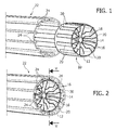
- Figures 1 and 2 show the option of coupling a "primary" heat sink 10 as described above to an auxiliary or "secondary" heat sink 22 comprising for example a heat-dissipating material that may be the same as or different to the material used in the heat sink 10, for example metal (for example, aluminum) plastics, heat-conducting plastics and heat-conducting ceramics.
- a "primary" heat sink 10 as described above
- an auxiliary or "secondary” heat sink 22 comprising for example a heat-dissipating material that may be the same as or different to the material used in the heat sink 10, for example metal (for example, aluminum) plastics, heat-conducting plastics and heat-conducting ceramics.
- the secondary heat sink 22 is a shaped tube that can be fitted onto the primary heat sink 10.
- the secondary heat sink 22 may be a profile with internal axial ribs 24 that can come into contact with the casing wall 12 of the primary heat sink 10, notably with the strips 20 of thermal interface material on the casing surface of the primary heat sink 10.
- the primary heat sink 10 and the secondary heat sink 22 may be joined to one another by inserting the primary heat sink 10 into the axial cavity of the tubular body of the secondary heat sink 22 such as to create a composite heat-sink unit providing better heat-dissipation performance than the primary heat sink 10 on its own.
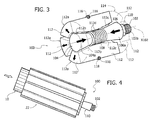
- Figure 3 is a schematic representation, indicated as a whole with reference sign 100, of a tool that can be used to radially dilate the secondary heat sink 22 to enable the coupling between the two heat sinks 10 and 20 with the strips of thermal interface material 20 pressed (uniformly) against the casing surface 12 of the primary heat sink 10 with a uniform force generated by the radial elastic contraction of the secondary heat sink 22.
- the dilation tool 100 may have a main shaft 102 extending along an axis X102 and having an enlarged head 104 at one extremity.
- the enlarged head 104 may have a flat end face and a peripheral casing surface, indicated with reference sign 104a, diverging towards the flat end face and forming in several embodiments a (frusto) conical shape.
- reference sign 106 indicates an annular body formed substantially identically to the enlarged head 104, but having a different orientation.
- the annular body 106 may have a side casing surface 106a, which is also divergent, for example forming a (frusto) conical shape.
- the annular body 106 can be fitted onto the shaft 102 in the opposite direction to the enlarged head 104, i.e. with the two divergent surfaces 104a and 106a widening/diverging in mutually opposing directions.
- the orientation is such that the radial dimensions of the surfaces 104a and 106a are lowest at the extremities that face one another and highest at the opposing extremities.
- a spring 108 may be placed between the enlarged head 104 and the annular body 106, pushing the annular body 106 away from the enlarged head 104, while the annular body 106 can be moved towards the enlarged head 104 by acting on an actuating nut or cylinder 110 screwed onto a threaded extremity 102a of the shaft 102.
- the arrangement shown is therefore such that the annular body 106 can be moved towards or away from the enlarged head 104 by tightening or loosening the nut or cylinder 110.
- thrust sectors 112 for example in the form of cylindrical sectors, each having a tile-shaped external surface 112a.
- the schematic view in figure 3 relates to the presence of sectors 112, each of which has an angular extension of approximately 60°. Consequently, the tool 100 shown in figure 3 has six of these sectors 112 arranged about the shaft 102, of which only three are shown with full lines to simplify the illustration.
- the sides of the sectors 112 facing the shaft 102 may have an overall V-shaped surface with two sections 112b and 112c inclined at an angle complementary to the conical surfaces 104a and 106a of the enlarged head 104 and of the annular body 106.
- the sections 112b and 112c may have a rounded concave shape complementing the rounded convex shape of the conical surfaces 104a and 106a.
- the sectors 112 can be held in position on the shaft 102 and returned to the radially contracted position when the nut 110 is loosened using known means, for example with one or more elastic annular bands (for example similar to 0-rings) 116 arranged in one or more annular grooves 118 formed in the casing surface 112a of the sectors 112.
- one or more elastic annular bands for example similar to 0-rings
- the axial extension of the tool 110 may be selected such that the tool 100 is "shorter" than the secondary heat sink 22. Consequently, when the tool 100 is inserted into the heat sink 22 from one extremity thereof, as shown in figure 4 , an axial section long enough to enable the insertion of the primary heat sink 10 remains free at the opposite extremity of the heat sink 22, as shown schematically on the left-hand side of figure 4 .
- this insertion may be facilitated by the fact that the external radial dimensions of the primary heat sink 10 (defined in practice by the strips 20) and the internal radial dimensions of the secondary heat sink 22 (defined in practice by the internal extremities of the axial ribs 24, which protrude into the tubular body of the secondary heat sink 22) may be chosen to be practically identical to one another.
- the primary heat sink 10 may therefore be inserted into the secondary heat sink 22 with no appreciable interference when the secondary heat sink 22 has been radially expanded using the tool 100 according to the method described above, for example by acting on the nut 110 to radially dilate the sectors 112 such as to apply a radial expansion force to the heat sink 22.
- this force may cause a limited elastic dilation of the heat sink 22, in particular of the radially internal extremities of the ribs 24.
- the primary heat sink 10 may be inserted into the secondary heat sink 22.
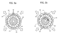
- this may be achieved, as shown schematically in figure 5a , either by sliding the primary heat sink 10 axially into the secondary heat sink 22 with the strips 20 kept in line with the spaces between the ribs 24 (distributed in an angularly uniform manner on the internal surface of the secondary heat sink 22), or with the strips 20 of thermal interface material angularly offset in relation to the ribs 24 of the secondary heat sink 22.
- the strips 20 may be assembled on the casing wall 12 of the primary heat sink 10 (for example placing the strips 20 in axial channels formed in the casing wall 12) in a cog arrangement (more specifically a ratchet wheel arrangement), i.e. ensuring that one side of each strip 20 is closer to the hub 14 than the opposite side of the same strip.
- the primary heat sink 10 and the secondary heat sink 22 are able to move axially in relation to one another. This makes it possible, for example, to adjust and/or change the axial assembly condition of the heat sink 10 inside the secondary heat sink 22, for example as a function of the dimensions of the lighting device assembled on the primary heat sink 10.
- the primary heat sink 10 and the secondary heat sink 22 may be rotated in relation to one another (in the present embodiment, it is assumed that said relative movement occurs such that the heat sink 10 rotates clockwise inside the secondary heat sink 22) and the strips 20 are matched to the distal extremities of the ribs 24.
- the tool 100 can again be actuated, for example to loosen the nut or cylinder 110 such as to reduce the radial expansion force previously applied by the tool 100 to the secondary heat sink.
- the secondary heat sink 22 returns elastically to a radially contracted condition in which the strips of thermal interface material 20 are pressed (with a force distributed uniformly throughout the facing surfaces of the heat sinks 10 and 22) between the external surface of the primary heat sink 10 and the internal surface of the secondary heat sink 20 (more specifically, the radially internal extremities of the ribs of this latter).
Landscapes
- Engineering & Computer Science (AREA)
- General Engineering & Computer Science (AREA)
- Cooling Or The Like Of Electrical Apparatus (AREA)
- Arrangement Of Elements, Cooling, Sealing, Or The Like Of Lighting Devices (AREA)
Applications Claiming Priority (1)
| Application Number | Priority Date | Filing Date | Title |
|---|---|---|---|
| ITTO20120786 | 2012-09-12 |
Publications (3)
| Publication Number | Publication Date |
|---|---|
| EP2708810A2 true EP2708810A2 (de) | 2014-03-19 |
| EP2708810A3 EP2708810A3 (de) | 2014-05-07 |
| EP2708810B1 EP2708810B1 (de) | 2016-01-06 |
Family
ID=46982795
Family Applications (1)
| Application Number | Title | Priority Date | Filing Date |
|---|---|---|---|
| EP13182216.5A Not-in-force EP2708810B1 (de) | 2012-09-12 | 2013-08-29 | Verfahren zur Montage von Kühlkörpern und zugehöriges Werkzeug |
Country Status (1)
| Country | Link |
|---|---|
| EP (1) | EP2708810B1 (de) |
Cited By (2)
| Publication number | Priority date | Publication date | Assignee | Title |
|---|---|---|---|---|
| CN104048278A (zh) * | 2014-06-19 | 2014-09-17 | 江苏华兴电子有限公司 | 具有高散热能力的散热器及led照明灯 |
| ITUA20161520A1 (it) * | 2016-03-10 | 2017-09-10 | A A G Stucchi S R L | Dispositivo dissipatore di calore in particolare per l’impiego in un apparecchio di illuminazione tubolare e apparecchio di illuminazione tubolare impiegante lo stesso |
Family Cites Families (6)
| Publication number | Priority date | Publication date | Assignee | Title |
|---|---|---|---|---|
| WO2010102594A1 (de) * | 2009-03-11 | 2010-09-16 | Joachim Springer | Unterwasserscheinwerfer |
| US7997763B2 (en) * | 2009-03-31 | 2011-08-16 | Heatron, Inc. | Multi-heat sink LED device |
| US20110249406A1 (en) * | 2009-06-20 | 2011-10-13 | LEDAdventures LLC | Heat dissipation system for electrical components |
| US20100321893A1 (en) * | 2009-06-20 | 2010-12-23 | Peter Scott Andrews | Heat Dissipation Packaging for Electrical Components |
| US20110051430A1 (en) * | 2009-08-25 | 2011-03-03 | Shih-Ming Chen | Assembly structure for led fixture |
| DE102010002235A1 (de) * | 2010-02-23 | 2011-08-25 | Zumtobel Lighting GmbH, 32657 | Kühlkörper für eine Lichtquelle |
-
2013
- 2013-08-29 EP EP13182216.5A patent/EP2708810B1/de not_active Not-in-force
Non-Patent Citations (1)
| Title |
|---|
| None |
Cited By (2)
| Publication number | Priority date | Publication date | Assignee | Title |
|---|---|---|---|---|
| CN104048278A (zh) * | 2014-06-19 | 2014-09-17 | 江苏华兴电子有限公司 | 具有高散热能力的散热器及led照明灯 |
| ITUA20161520A1 (it) * | 2016-03-10 | 2017-09-10 | A A G Stucchi S R L | Dispositivo dissipatore di calore in particolare per l’impiego in un apparecchio di illuminazione tubolare e apparecchio di illuminazione tubolare impiegante lo stesso |
Also Published As
| Publication number | Publication date |
|---|---|
| EP2708810B1 (de) | 2016-01-06 |
| EP2708810A3 (de) | 2014-05-07 |
Similar Documents
| Publication | Publication Date | Title |
|---|---|---|
| ES2374167T3 (es) | Acoplamiento rápido. | |
| CN1107171C (zh) | 用于将机器零件同轴安装在轴上的装置和方法 | |
| US9194417B2 (en) | Screwable element for fastening a conduit to a counter-piece | |
| US9593829B2 (en) | Hinge-mounted rotating base spotlight | |
| CN102410514B (zh) | 散热结构和具有该散热结构的射灯 | |
| US6604575B1 (en) | Heat exchange apparatus | |
| EP2708810B1 (de) | Verfahren zur Montage von Kühlkörpern und zugehöriges Werkzeug | |
| US20170291190A1 (en) | Assembly for a carrier for carrying a caulk cartridge and caulking gun | |
| US9827588B2 (en) | Assembly for a carrier for carrying a caulk cartridge and caulking gun | |
| JP2016185063A (ja) | 固定子アセンブリならびにそのような固定子アセンブリを備えた磁気ベアリングや電気モータ | |
| US20200078925A1 (en) | Stepless telescoping mechanism and stepless telescopic screwdriver | |
| US9568037B2 (en) | Machine element mounting assembly | |
| TW200530519A (en) | Mounting device | |
| US9890932B2 (en) | Luminaire | |
| CN106996442A (zh) | 具有能够在其中由螺母输送流体的冷却通道的致动器 | |
| EP2587139A1 (de) | Kühlkörper und dazugehöriger Kühlkörperverbund | |
| CN108367746A (zh) | 制动压力控制器 | |
| CN101309569B (zh) | 扣具及散热装置组合 | |
| US20170241284A1 (en) | Wheel disc arrangement | |
| GB2568565A (en) | Precision positioning device | |
| EP3473554B1 (de) | Flugzeugaussenlichteinheit | |
| US20160169499A1 (en) | Illuminating device | |
| US5163541A (en) | Mechanism useful as a slip clutch or brake | |
| US20140027215A1 (en) | Heat-dissipating device for hydraulic brake system | |
| US20160161092A1 (en) | Securing mechanism for a lamp bulb |
Legal Events
| Date | Code | Title | Description |
|---|---|---|---|
| PUAI | Public reference made under article 153(3) epc to a published international application that has entered the european phase |
Free format text: ORIGINAL CODE: 0009012 |
|
| AK | Designated contracting states |
Kind code of ref document: A2 Designated state(s): AL AT BE BG CH CY CZ DE DK EE ES FI FR GB GR HR HU IE IS IT LI LT LU LV MC MK MT NL NO PL PT RO RS SE SI SK SM TR |
|
| AX | Request for extension of the european patent |
Extension state: BA ME |
|
| PUAL | Search report despatched |
Free format text: ORIGINAL CODE: 0009013 |
|
| AK | Designated contracting states |
Kind code of ref document: A3 Designated state(s): AL AT BE BG CH CY CZ DE DK EE ES FI FR GB GR HR HU IE IS IT LI LT LU LV MC MK MT NL NO PL PT RO RS SE SI SK SM TR |
|
| AX | Request for extension of the european patent |
Extension state: BA ME |
|
| RIC1 | Information provided on ipc code assigned before grant |
Ipc: F21V 29/00 20060101AFI20140331BHEP Ipc: F21Y 101/02 20060101ALN20140331BHEP |
|
| 17P | Request for examination filed |
Effective date: 20141107 |
|
| RBV | Designated contracting states (corrected) |
Designated state(s): AL AT BE BG CH CY CZ DE DK EE ES FI FR GB GR HR HU IE IS IT LI LT LU LV MC MK MT NL NO PL PT RO RS SE SI SK SM TR |
|
| REG | Reference to a national code |
Ref country code: DE Ref legal event code: R079 Ref document number: 602013004448 Country of ref document: DE Free format text: PREVIOUS MAIN CLASS: F21V0029000000 Ipc: F21V0029710000 |
|
| GRAP | Despatch of communication of intention to grant a patent |
Free format text: ORIGINAL CODE: EPIDOSNIGR1 |
|
| RIC1 | Information provided on ipc code assigned before grant |
Ipc: F21V 29/71 20150101AFI20150811BHEP Ipc: F21Y 101/02 20060101ALN20150811BHEP |
|
| INTG | Intention to grant announced |
Effective date: 20150902 |
|
| GRAS | Grant fee paid |
Free format text: ORIGINAL CODE: EPIDOSNIGR3 |
|
| GRAA | (expected) grant |
Free format text: ORIGINAL CODE: 0009210 |
|
| AK | Designated contracting states |
Kind code of ref document: B1 Designated state(s): AL AT BE BG CH CY CZ DE DK EE ES FI FR GB GR HR HU IE IS IT LI LT LU LV MC MK MT NL NO PL PT RO RS SE SI SK SM TR |
|
| REG | Reference to a national code |
Ref country code: GB Ref legal event code: FG4D |
|
| REG | Reference to a national code |
Ref country code: CH Ref legal event code: EP |
|
| REG | Reference to a national code |
Ref country code: IE Ref legal event code: FG4D |
|
| REG | Reference to a national code |
Ref country code: AT Ref legal event code: REF Ref document number: 769163 Country of ref document: AT Kind code of ref document: T Effective date: 20160215 |
|
| REG | Reference to a national code |
Ref country code: DE Ref legal event code: R096 Ref document number: 602013004448 Country of ref document: DE |
|
| REG | Reference to a national code |
Ref country code: LT Ref legal event code: MG4D |
|
| REG | Reference to a national code |
Ref country code: NL Ref legal event code: MP Effective date: 20160106 |
|
| PG25 | Lapsed in a contracting state [announced via postgrant information from national office to epo] |
Ref country code: NL Free format text: LAPSE BECAUSE OF FAILURE TO SUBMIT A TRANSLATION OF THE DESCRIPTION OR TO PAY THE FEE WITHIN THE PRESCRIBED TIME-LIMIT Effective date: 20160106 |
|
| PG25 | Lapsed in a contracting state [announced via postgrant information from national office to epo] |
Ref country code: ES Free format text: LAPSE BECAUSE OF FAILURE TO SUBMIT A TRANSLATION OF THE DESCRIPTION OR TO PAY THE FEE WITHIN THE PRESCRIBED TIME-LIMIT Effective date: 20160106 Ref country code: NO Free format text: LAPSE BECAUSE OF FAILURE TO SUBMIT A TRANSLATION OF THE DESCRIPTION OR TO PAY THE FEE WITHIN THE PRESCRIBED TIME-LIMIT Effective date: 20160406 Ref country code: FI Free format text: LAPSE BECAUSE OF FAILURE TO SUBMIT A TRANSLATION OF THE DESCRIPTION OR TO PAY THE FEE WITHIN THE PRESCRIBED TIME-LIMIT Effective date: 20160106 Ref country code: HR Free format text: LAPSE BECAUSE OF FAILURE TO SUBMIT A TRANSLATION OF THE DESCRIPTION OR TO PAY THE FEE WITHIN THE PRESCRIBED TIME-LIMIT Effective date: 20160106 Ref country code: GR Free format text: LAPSE BECAUSE OF FAILURE TO SUBMIT A TRANSLATION OF THE DESCRIPTION OR TO PAY THE FEE WITHIN THE PRESCRIBED TIME-LIMIT Effective date: 20160407 |
|
| PG25 | Lapsed in a contracting state [announced via postgrant information from national office to epo] |
Ref country code: RS Free format text: LAPSE BECAUSE OF FAILURE TO SUBMIT A TRANSLATION OF THE DESCRIPTION OR TO PAY THE FEE WITHIN THE PRESCRIBED TIME-LIMIT Effective date: 20160106 Ref country code: LT Free format text: LAPSE BECAUSE OF FAILURE TO SUBMIT A TRANSLATION OF THE DESCRIPTION OR TO PAY THE FEE WITHIN THE PRESCRIBED TIME-LIMIT Effective date: 20160106 Ref country code: IS Free format text: LAPSE BECAUSE OF FAILURE TO SUBMIT A TRANSLATION OF THE DESCRIPTION OR TO PAY THE FEE WITHIN THE PRESCRIBED TIME-LIMIT Effective date: 20160506 Ref country code: PT Free format text: LAPSE BECAUSE OF FAILURE TO SUBMIT A TRANSLATION OF THE DESCRIPTION OR TO PAY THE FEE WITHIN THE PRESCRIBED TIME-LIMIT Effective date: 20160506 Ref country code: LV Free format text: LAPSE BECAUSE OF FAILURE TO SUBMIT A TRANSLATION OF THE DESCRIPTION OR TO PAY THE FEE WITHIN THE PRESCRIBED TIME-LIMIT Effective date: 20160106 Ref country code: PL Free format text: LAPSE BECAUSE OF FAILURE TO SUBMIT A TRANSLATION OF THE DESCRIPTION OR TO PAY THE FEE WITHIN THE PRESCRIBED TIME-LIMIT Effective date: 20160106 Ref country code: SE Free format text: LAPSE BECAUSE OF FAILURE TO SUBMIT A TRANSLATION OF THE DESCRIPTION OR TO PAY THE FEE WITHIN THE PRESCRIBED TIME-LIMIT Effective date: 20160106 |
|
| REG | Reference to a national code |
Ref country code: DE Ref legal event code: R097 Ref document number: 602013004448 Country of ref document: DE |
|
| PG25 | Lapsed in a contracting state [announced via postgrant information from national office to epo] |
Ref country code: DK Free format text: LAPSE BECAUSE OF FAILURE TO SUBMIT A TRANSLATION OF THE DESCRIPTION OR TO PAY THE FEE WITHIN THE PRESCRIBED TIME-LIMIT Effective date: 20160106 Ref country code: EE Free format text: LAPSE BECAUSE OF FAILURE TO SUBMIT A TRANSLATION OF THE DESCRIPTION OR TO PAY THE FEE WITHIN THE PRESCRIBED TIME-LIMIT Effective date: 20160106 |
|
| PLBE | No opposition filed within time limit |
Free format text: ORIGINAL CODE: 0009261 |
|
| STAA | Information on the status of an ep patent application or granted ep patent |
Free format text: STATUS: NO OPPOSITION FILED WITHIN TIME LIMIT |
|
| PG25 | Lapsed in a contracting state [announced via postgrant information from national office to epo] |
Ref country code: RO Free format text: LAPSE BECAUSE OF FAILURE TO SUBMIT A TRANSLATION OF THE DESCRIPTION OR TO PAY THE FEE WITHIN THE PRESCRIBED TIME-LIMIT Effective date: 20160106 Ref country code: CZ Free format text: LAPSE BECAUSE OF FAILURE TO SUBMIT A TRANSLATION OF THE DESCRIPTION OR TO PAY THE FEE WITHIN THE PRESCRIBED TIME-LIMIT Effective date: 20160106 Ref country code: SK Free format text: LAPSE BECAUSE OF FAILURE TO SUBMIT A TRANSLATION OF THE DESCRIPTION OR TO PAY THE FEE WITHIN THE PRESCRIBED TIME-LIMIT Effective date: 20160106 Ref country code: SM Free format text: LAPSE BECAUSE OF FAILURE TO SUBMIT A TRANSLATION OF THE DESCRIPTION OR TO PAY THE FEE WITHIN THE PRESCRIBED TIME-LIMIT Effective date: 20160106 |
|
| 26N | No opposition filed |
Effective date: 20161007 |
|
| PG25 | Lapsed in a contracting state [announced via postgrant information from national office to epo] |
Ref country code: BE Free format text: LAPSE BECAUSE OF FAILURE TO SUBMIT A TRANSLATION OF THE DESCRIPTION OR TO PAY THE FEE WITHIN THE PRESCRIBED TIME-LIMIT Effective date: 20160106 |
|
| PG25 | Lapsed in a contracting state [announced via postgrant information from national office to epo] |
Ref country code: BG Free format text: LAPSE BECAUSE OF FAILURE TO SUBMIT A TRANSLATION OF THE DESCRIPTION OR TO PAY THE FEE WITHIN THE PRESCRIBED TIME-LIMIT Effective date: 20160406 Ref country code: SI Free format text: LAPSE BECAUSE OF FAILURE TO SUBMIT A TRANSLATION OF THE DESCRIPTION OR TO PAY THE FEE WITHIN THE PRESCRIBED TIME-LIMIT Effective date: 20160106 |
|
| PG25 | Lapsed in a contracting state [announced via postgrant information from national office to epo] |
Ref country code: MC Free format text: LAPSE BECAUSE OF FAILURE TO SUBMIT A TRANSLATION OF THE DESCRIPTION OR TO PAY THE FEE WITHIN THE PRESCRIBED TIME-LIMIT Effective date: 20160106 |
|
| REG | Reference to a national code |
Ref country code: CH Ref legal event code: PL |
|
| PG25 | Lapsed in a contracting state [announced via postgrant information from national office to epo] |
Ref country code: CH Free format text: LAPSE BECAUSE OF NON-PAYMENT OF DUE FEES Effective date: 20160831 Ref country code: LI Free format text: LAPSE BECAUSE OF NON-PAYMENT OF DUE FEES Effective date: 20160831 |
|
| REG | Reference to a national code |
Ref country code: FR Ref legal event code: ST Effective date: 20170428 |
|
| REG | Reference to a national code |
Ref country code: IE Ref legal event code: MM4A |
|
| PG25 | Lapsed in a contracting state [announced via postgrant information from national office to epo] |
Ref country code: FR Free format text: LAPSE BECAUSE OF NON-PAYMENT OF DUE FEES Effective date: 20160831 Ref country code: IE Free format text: LAPSE BECAUSE OF NON-PAYMENT OF DUE FEES Effective date: 20160829 |
|
| PG25 | Lapsed in a contracting state [announced via postgrant information from national office to epo] |
Ref country code: LU Free format text: LAPSE BECAUSE OF NON-PAYMENT OF DUE FEES Effective date: 20160829 |
|
| PGFP | Annual fee paid to national office [announced via postgrant information from national office to epo] |
Ref country code: IT Payment date: 20170828 Year of fee payment: 5 Ref country code: DE Payment date: 20170822 Year of fee payment: 5 Ref country code: GB Payment date: 20170822 Year of fee payment: 5 |
|
| PG25 | Lapsed in a contracting state [announced via postgrant information from national office to epo] |
Ref country code: CY Free format text: LAPSE BECAUSE OF FAILURE TO SUBMIT A TRANSLATION OF THE DESCRIPTION OR TO PAY THE FEE WITHIN THE PRESCRIBED TIME-LIMIT Effective date: 20160106 Ref country code: HU Free format text: LAPSE BECAUSE OF FAILURE TO SUBMIT A TRANSLATION OF THE DESCRIPTION OR TO PAY THE FEE WITHIN THE PRESCRIBED TIME-LIMIT; INVALID AB INITIO Effective date: 20130829 |
|
| PG25 | Lapsed in a contracting state [announced via postgrant information from national office to epo] |
Ref country code: MK Free format text: LAPSE BECAUSE OF FAILURE TO SUBMIT A TRANSLATION OF THE DESCRIPTION OR TO PAY THE FEE WITHIN THE PRESCRIBED TIME-LIMIT Effective date: 20160106 Ref country code: MT Free format text: LAPSE BECAUSE OF NON-PAYMENT OF DUE FEES Effective date: 20160831 |
|
| PG25 | Lapsed in a contracting state [announced via postgrant information from national office to epo] |
Ref country code: TR Free format text: LAPSE BECAUSE OF FAILURE TO SUBMIT A TRANSLATION OF THE DESCRIPTION OR TO PAY THE FEE WITHIN THE PRESCRIBED TIME-LIMIT Effective date: 20160106 Ref country code: AL Free format text: LAPSE BECAUSE OF FAILURE TO SUBMIT A TRANSLATION OF THE DESCRIPTION OR TO PAY THE FEE WITHIN THE PRESCRIBED TIME-LIMIT Effective date: 20160106 |
|
| RIC2 | Information provided on ipc code assigned after grant |
Ipc: F21V 29/71 20150101AFI20150811BHEP Ipc: F21Y 101/02 20000101ALN20150811BHEP |
|
| REG | Reference to a national code |
Ref country code: DE Ref legal event code: R119 Ref document number: 602013004448 Country of ref document: DE |
|
| GBPC | Gb: european patent ceased through non-payment of renewal fee |
Effective date: 20180829 |
|
| REG | Reference to a national code |
Ref country code: AT Ref legal event code: UEP Ref document number: 769163 Country of ref document: AT Kind code of ref document: T Effective date: 20160106 |
|
| PG25 | Lapsed in a contracting state [announced via postgrant information from national office to epo] |
Ref country code: DE Free format text: LAPSE BECAUSE OF NON-PAYMENT OF DUE FEES Effective date: 20190301 Ref country code: IT Free format text: LAPSE BECAUSE OF NON-PAYMENT OF DUE FEES Effective date: 20180829 |
|
| REG | Reference to a national code |
Ref country code: AT Ref legal event code: MM01 Ref document number: 769163 Country of ref document: AT Kind code of ref document: T Effective date: 20180829 |
|
| PG25 | Lapsed in a contracting state [announced via postgrant information from national office to epo] |
Ref country code: GB Free format text: LAPSE BECAUSE OF NON-PAYMENT OF DUE FEES Effective date: 20180829 |
|
| PG25 | Lapsed in a contracting state [announced via postgrant information from national office to epo] |
Ref country code: AT Free format text: LAPSE BECAUSE OF NON-PAYMENT OF DUE FEES Effective date: 20180829 |