EP2708467A2 - Lavatory reconfiguration system - Google Patents
Lavatory reconfiguration system Download PDFInfo
- Publication number
- EP2708467A2 EP2708467A2 EP13184546.3A EP13184546A EP2708467A2 EP 2708467 A2 EP2708467 A2 EP 2708467A2 EP 13184546 A EP13184546 A EP 13184546A EP 2708467 A2 EP2708467 A2 EP 2708467A2
- Authority
- EP
- European Patent Office
- Prior art keywords
- lavatory
- moveable partition
- toilet
- configuration
- door
- Prior art date
- Legal status (The legal status is an assumption and is not a legal conclusion. Google has not performed a legal analysis and makes no representation as to the accuracy of the status listed.)
- Granted
Links
- 238000005192 partition Methods 0.000 claims abstract description 156
- 238000000034 method Methods 0.000 claims abstract description 33
- 238000004519 manufacturing process Methods 0.000 description 15
- 230000008569 process Effects 0.000 description 7
- 238000010586 diagram Methods 0.000 description 6
- 238000012423 maintenance Methods 0.000 description 4
- 230000004048 modification Effects 0.000 description 4
- 238000012986 modification Methods 0.000 description 4
- 239000000463 material Substances 0.000 description 3
- 239000003381 stabilizer Substances 0.000 description 3
- 230000008859 change Effects 0.000 description 2
- 230000010354 integration Effects 0.000 description 2
- 238000009419 refurbishment Methods 0.000 description 2
- 239000002131 composite material Substances 0.000 description 1
- 230000007613 environmental effect Effects 0.000 description 1
- 239000002184 metal Substances 0.000 description 1
- 230000008520 organization Effects 0.000 description 1
Images


Classifications
-
- B—PERFORMING OPERATIONS; TRANSPORTING
- B64—AIRCRAFT; AVIATION; COSMONAUTICS
- B64D—EQUIPMENT FOR FITTING IN OR TO AIRCRAFT; FLIGHT SUITS; PARACHUTES; ARRANGEMENTS OR MOUNTING OF POWER PLANTS OR PROPULSION TRANSMISSIONS IN AIRCRAFT
- B64D11/00—Passenger or crew accommodation; Flight-deck installations not otherwise provided for
- B64D11/02—Toilet fittings
-
- B—PERFORMING OPERATIONS; TRANSPORTING
- B64—AIRCRAFT; AVIATION; COSMONAUTICS
- B64D—EQUIPMENT FOR FITTING IN OR TO AIRCRAFT; FLIGHT SUITS; PARACHUTES; ARRANGEMENTS OR MOUNTING OF POWER PLANTS OR PROPULSION TRANSMISSIONS IN AIRCRAFT
- B64D11/00—Passenger or crew accommodation; Flight-deck installations not otherwise provided for
- B64D11/0023—Movable or removable cabin dividers, e.g. for class separation
Definitions
- the present disclosure relates generally to aircraft and, in particular, to lavatories in aircraft. Still more particularly, the present disclosure relates to providing a desired level of access to lavatories in an aircraft.
- Handicap access includes access for passengers in wheelchairs.
- Standards for handicap access in an aircraft are often specified through regulations and laws.
- the lavatories designed for accommodating handicapped passengers require more space than standard lavatories in an aircraft.
- a lavatory may be redesigned to provide the desired amount of space for access by handicapped passengers.
- the redesign may be performed for an aircraft being manufactured or the redesign may be used to refurbish existing aircraft to provide the desired access for handicapped passengers.
- This redesign may take various forms. For example, the perimeter of the lavatory may be redesigned such that a desired amount of space is present with a desired configuration within the lavatory.
- the lavatories may be redesigned to extend into space normally used for aisles or other purposes when access by a handicapped passenger is needed.
- a more efficient use of space may involve two lavatories being positioned next to each other and reconfigured to provide more access as a single lavatory for a handicapped passenger when needed.
- lavatories that are convertible from two lavatories into a single lavatory also may be more difficult to reconfigure and may not be as efficient as desired. Therefore, it would be desirable to have a method and apparatus that takes into account at least some of the issues discussed above, as well as other possible issues.
- an apparatus comprises a moveable partition.
- the moveable partition is configured for use with a first lavatory and a second lavatory.
- the moveable partition is further configured to separate the first lavatory and the second lavatory into separate spaces within a fixed perimeter for the first lavatory and the second lavatory when the moveable partition is in a first configuration.
- the moveable partition is further configured to define a single space within the fixed perimeter when the moveable partition is in a second configuration.
- the moveable partition is connected to a door for the first lavatory in the second configuration.
- a method for reconfiguring lavatory space in an aircraft is present.
- a moveable partition for a first lavatory and a second lavatory is moved between a first configuration and a second configuration.
- the first configuration separates the first lavatory and the second lavatory into separate spaces within a fixed perimeter for the first lavatory and the second lavatory.
- the second configuration has a single space present within the fixed perimeter.
- the moveable partition is connected to a door for the first lavatory in the second configuration.
- a method of operating an aircraft is present.
- the aircraft is operated in which a first lavatory and a second lavatory are located in the aircraft with a moveable partition configured for use with the first lavatory and the second lavatory.
- the moveable partition is configured to separate the first lavatory and the second lavatory into separate spaces within a fixed perimeter for the first lavatory and the second lavatory when the moveable partition is in a first configuration.
- the moveable partition is further configured to define a single space within the fixed perimeter when the moveable partition is in a second configuration.
- the moveable partition is connected to a door for the first lavatory in the second configuration.
- the illustrative embodiments recognize and take into account one or more different considerations. For example, the illustrative embodiments recognize and take into account that it may be desirable to maintain the same perimeter for a lavatory rather than encroaching on space in the cabin through changing the perimeter of the lavatory.
- the illustrative embodiments also recognize and take into account that existing systems that convert two lavatories into a single larger lavatory for use by passengers who may require more space may be more difficult to reconfigure than desired. Further, these designs also may be less efficient than desired. For example, the illustrative embodiments recognize and take into account that a wall dividing two lavatories may be folded back against an interior wall of the two lavatories to provide additional space for a handicapped passenger. The reconfiguration of a folding wall against an interior wall of the two lavatories may provide this additional space for a handicapped passenger or other passengers needing more space in a lavatory.
- this type of reconfiguration may reduce or block access to different components in the combined lavatories.
- the reconfiguration of the folding wall may block access to one or both of the two toilets and also may block access to a sink in the lavatories.
- maneuvering within the lavatories may be more difficult than desired.
- an apparatus comprises a moveable partition.
- the moveable partition is configured for use with a first lavatory and a second lavatory.
- the moveable partition is configured to separate the first lavatory and the second lavatory into separate spaces with a fixed perimeter for the first lavatory and the second lavatory when the moveable partition is in a first configuration.
- the moveable partition is configured to define a single space within the fixed perimeter.
- the moveable partition is connected to a door for the first lavatory in the second configuration.
- aircraft 100 has wing 102 and wing 104 attached to fuselage 106.
- Aircraft 100 includes engine 108 attached to wing 102 and engine 110 attached to wing 104.
- Fuselage 106 has nose section 112 and tail section 114.
- Horizontal stabilizer 116, horizontal stabilizer 118, and vertical stabilizer 120 are attached to tail section 114 of fuselage 106.
- Aircraft 100 is an example of an aircraft in which a lavatory access system may be implemented in accordance with an illustrative embodiment.
- section 121 illustrates an exposed view in which interior 122 of passenger cabin 124 in fuselage 106 of aircraft 100 is seen.
- section 121 of passenger cabin 124 includes lavatory area 126 as seen in this exposed view.
- lavatory area 126 includes first lavatory 128 and second lavatory 130.
- lavatories are examples of lavatories that may be reconfigured to allow greater access to handicapped passengers in accordance with an illustrative embodiment.
- these lavatories may be reconfigured without changing perimeter 132 for first lavatory 128 and second lavatory 130. In other words, perimeter 132 remains fixed in these illustrative examples.
- platform 200 may be aircraft 202.
- Aircraft 100 in Figure 1 is an example of one physical implementation for aircraft 202 shown in block form in this figure.
- platform 200 includes lavatory area 204.
- Lavatory area 204 is an area within platform 200 in which first lavatory 206 and second lavatory 208 may be located.
- first lavatory 206 and second lavatory 208 are adjacent to each other.
- Perimeter 210 is a boundary around first lavatory 206 and second lavatory 208.
- perimeter 210 takes the form of fixed perimeter 212 that extends around first lavatory 206 and second lavatory 208.
- perimeter 210 is fixed perimeter 212 because walls 214 forming perimeter 210 around first lavatory 206 and second lavatory 208 are fixed and do not move into other areas within lavatory area 204 or other areas within platform 200.
- first lavatory 206 includes first wash basin 216 and first toilet 218.
- Second lavatory 208 includes second wash basin 220 and second toilet 222. Additionally, first lavatory 206 has first door 224 and second lavatory 208 has second door 226 located within walls 214.
- moveable partition 228 is present in lavatory area 204 and forms at least part of wall 230 between first lavatory 206 and second lavatory 208.
- Moveable partition 228 is a structure that may be used to reconfigure space for first lavatory 206 and second lavatory 208 within walls 214.
- Moveable partition 228 may be comprised of different types of materials.
- moveable partition 228 may be comprised of a composite material, a metal, or some other suitable type of material.
- Moveable partition 228 may have first configuration 232 and second configuration 234. In particular, moveable partition 228 may be moved between first configuration 232 and second configuration 234.
- moveable partition 228 when moveable partition 228 is in first configuration 232, moveable partition 228 forms at least a portion of wall 230.
- moveable partition 228 In first configuration 232, moveable partition 228 is configured to separate first lavatory 206 and second lavatory 208 into spaces 236.
- spaces 236 include first space 238 and second space 240.
- First space 238 is space within first lavatory 206 in perimeter 210.
- Second space 240 is space within second lavatory 208 in perimeter 210.
- moveable partition 228 When moveable partition 228 is in second configuration 234, moveable partition 228 defines single space 242 for first lavatory 206 and second lavatory 208 instead of spaces 236.
- Single space 242 may provide additional room for passengers such as a family, a handicapped passenger, or other types of passengers who may require additional room within lavatory area 204.
- moveable partition 228 may be connected to first door 224 for first lavatory 206 when moveable partition 228 is in second configuration 234.
- a first component, moveable partition 228, "connected to" a second component, first door 224 means that the first component can be connected directly or indirectly to the second component.
- additional components may be present between the first component and the second component.
- the first component is considered to be indirectly connected to the second component when one or more additional components are present between the two components. When the first component is directly connected to the second component, no additional components are present between the two components.
- moveable partition 228 may be connected to first door 224 by connector system 246.
- connector system 246 may be, for example, a latch.
- the latch may be a magnetic latch.
- Hinge system 244 is associated with first door 224 and moveable partition 228. Hinge system 244 is configured to allow moveable partition 228 to rotate into a position against first door 224. Hinge system 244 also may allow moveable partition 228 to fold when moveable partition 228 is comprised of sections 248. In this particular example, moveable partition 228 is configured to be folded against first door 224 when moveable partition 228 is in second configuration 234.
- platform 200 and lavatory area 204 in platform 200 is not meant to imply physical or architectural limitations to the manner in which an illustrative embodiment may be implemented.
- Other components in addition to or in place of the ones illustrated may be used. Some components may be unnecessary.
- the blocks are presented to illustrate some functional components. One or more of these blocks may be combined, divided, or combined and divided into different blocks when implemented in an illustrative embodiment.
- platform 200 may be implemented in other forms.
- Platform 200 may be, for example, a mobile platform, a stationary platform, a land-based structure, an aquatic-based structure, and a space-based structure. More specifically, platform 200 may be a surface ship, a train, a spacecraft, a space station, a submarine, a power plant, a house, an office, a manufacturing facility, a building, and other suitable platforms.
- a third lavatory may be adjacent to one of first lavatory 206 and second lavatory 208.
- the common wall between the third lavatory and the other lavatory may also be formed using another moveable partition similar to moveable partition 228.
- both common walls of the middle lavatory may be moveable partitions such that an even larger space is available if desired.
- first lavatory 128 and second lavatory 130 are examples of physical implementations for first lavatory 206 and second lavatory 208 in Figure 2 .
- first lavatory 128 includes first toilet 300 and second lavatory 130 includes second toilet 302.
- first space 304 and second space 306 are located within perimeter 132.
- First space 304 and second space 306 are defined by perimeter 132 and guide 308.
- first space 304 and second space 306 within perimeter 132 may be combined to form single space 310.
- FIG. 4 an illustration of a plan view of a first lavatory and a second lavatory within a lavatory area is depicted in accordance with an illustrative embodiment.
- first wash basin 400 is shown in first lavatory 128. Additionally, second wash basin 402 is shown in second lavatory 130.
- walls 404 define perimeter 132.
- Perimeter 132 defines first space 304 and second space 306 for first lavatory 128 and second lavatory 130.
- first space 304 and second space 306 may be defined within perimeter 132 by moveable partition 406.
- first door 408 is a first door for first lavatory 128.
- First door 408 is located in first opening 410 in walls 404.
- Second door 412 is a door for second lavatory 130.
- Second door 412 is located in second opening 414 in walls 404.
- moveable partition 406 has first end 416 and second end 418.
- moveable partition 406 is comprised of first section 422 and second section 424.
- First end 416 of moveable partition 406 is connected to first door 408 by hinge system 425 in these illustrative examples.
- moveable partition 406 has first configuration 420 when moveable partition 406 defines first space 304 for first lavatory 128 and second space 306 for second lavatory 130 within perimeter 132.
- Moveable partition 406 may be placed into second configuration 426. Moveable partition 406 is shown in phantom in an intermediate position during its movement to the second configuration 426. In second configuration 426, moveable partition 406 may be folded against side 428 of first door 408. Both first door 408 and moveable partition 406 may be rotated about common axis 430 in the direction of arrow 432.
- first lavatory 128 and second lavatory 130 are no longer divided into first space 304 and second space 306. Instead, first space 304 and second space 306 are combined to form single space 310.
- Figures 5-10 are illustrations of a reconfiguration of space for first lavatory 128 and second lavatory 130 using moveable partition 406 in accordance with an illustrative embodiment. These figures illustrate different configurations for moveable partition 406 used to divide and combine space within first lavatory 128 and second lavatory 130.
- FIG. 5 an illustration of an isometric view of a first lavatory and a second lavatory in a lavatory area is depicted in accordance with an illustrative embodiment.
- an isometric view of lavatory area 126 with first lavatory 128 and second lavatory 130 is shown.
- first door 408 is shown in phantom to provide a better view of first space 304 in first lavatory 128.
- moveable partition 406 is shown in first configuration 420.
- moveable partition 406 defines first space 304 and second space 306.
- first lavatory 128 and second lavatory 130 may be used by different passengers.
- This configuration of space for first lavatory 128 and second lavatory 130 may be considered a normal configuration of space for these two lavatories.
- divider 500 is present.
- Divider 500 is located adjacent to at least one of first toilet 300 and second toilet 302.
- divider 500 is located between first toilet 300 and second toilet 302.
- Divider 500 is configured to move.
- divider 500 is rotatable and may be configured to rotate in the direction of arrow 502 toward wall 504.
- wall 504 is a fuselage wall.
- moveable partition 406 begins moving out of first configuration 420.
- moveable partition 406 begins rotating in the direction of arrow 432 about common axis 430.
- Hinge 602 in hinge system 425 provides for this movement.
- first section 422 and second section 424 fold relative to each other through hinge 604 in hinge system 425.
- FIG. 7 an illustration of movement of a moveable partition is depicted in accordance with an illustrative embodiment.
- first section 422 and section 424 of moveable partition 406 are folded against each other.
- moveable partition 406 is shown as having rotated further about common axis 430 in the direction of arrow 432.
- Figure 8 is an illustration of movement of a moveable partition in accordance with an illustrative embodiment.
- moveable partition 406 is in folded position 800 against first door 408.
- moveable partition 406 is connected to first door 408. This connection may be made through a connector system (not shown).
- divider 500 has been rotated toward wall 504 in the direction of arrow 502.
- moveable partition 406 is in second configuration 426 against first door 408.
- moveable partition 406 may be considered to be in second configuration 426 whenever moveable partition 406 has been moved such that both first space 304 and second space 306 may be used as single space 310.
- FIG. 9 an illustration of movement of a moveable partition is depicted in accordance with an illustrative embodiment.
- first door 408 is shown rotated in the direction of arrow 432 about common axis 430.
- moveable partition 406 also rotates with first door 408 in the direction of arrow 432 about common axis 430.
- first lavatory 128 and second lavatory 130 are configured to provide single space 310 within perimeter 132 for passenger 1000 located in wheelchair 1002.
- moveable partition 406 is in folded position 800 against side 428 of first door 408. Additionally, divider 500 has been rotated towards wall 504 in walls 404 to provide increased access to at least one of first toilet 300 in first lavatory 128 and second toilet 302 in second lavatory 130 as well as possibly other components for these two lavatories.
- first lavatory 128 and second lavatory 130 with moveable partition 406 in Figure 1 and Figures 3 -10 is not meant to imply limitations to the manner in which other lavatories may be implemented with moveable partitions.
- a moveable partition may have one or more additional sections in addition to first section 422 and second section 424 in other illustrative examples.
- FIG. 11 an illustration of a more detailed view of a hinge connection for a moveable partition is depicted in accordance with an illustrative embodiment.
- a more detailed illustration of hinge 602 is shown.
- section 1100 of hinge 602 is connected to first end 416 of first section 422 in moveable partition 406.
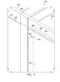
- FIG. 12 an illustration of movement for a hinge connection for a moveable partition is depicted in accordance with an illustrative embodiment.
- moveable partition 406 has been rotated against first door 408.
- section 1100 is configured to allow moveable partition 406 to move against first door 408 such that moveable partition 406 and first door 408 are substantially parallel to each other.
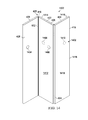
- FIG. 13 another illustration of movement for a hinge connection for a moveable partition is depicted in accordance with an illustrative embodiment.
- first door 408 has been opened to allow entry through first opening 410.
- moveable partition 406 is in folded position 800 against side 428 of first door 408.
- first door 408 and moveable partition 406 have rotated about common axis 430 in the direction of arrow 432.
- hinge system 425 illustrated in Figures 11-13 are only examples of one implementation of hinge system 244 shown in block form in Figure 2 .
- other types of hinges and other numbers of hinges may be used other than those shown in these figures.
- connector system 1400 is an example of one implementation for connector system 246 shown in block form in Figure 2 .
- Connector system 1400 may be a magnetic connector system in these illustrative examples.
- first door 408, moveable partition 406, and hinge system 425 are shown.
- the other components in lavatory area 126 in Figure 1 are not shown in this figure for purposes of explaining connector system 1400.
- connector system 1400 is comprised of magnetic connectors 1402.
- magnetic connectors 1402 comprise magnetic connector 1404, 1406, 1408, and 1410.
- Magnetic connector 1404 is located on side 428 of first door 408.
- Magnetic connector 1406 is located on first side 1412 of first section 422 of moveable partition 406.
- Magnetic connector 1408 is shown in phantom.
- Magnetic connector 1408 is located on second side 1414 of first section 422 of moveable partition 406.
- Magnetic connector 1410 is shown in phantom and is located on second side 1416 opposite of first side 1418 of second section 424 of moveable partition 406.
- magnetic connector 1408 on second side 1414 of first section 422 and magnetic connector 1410 on second side 1416 of second section 424 are configured to contact each other.
- Magnetic connector 1408 and magnetic connector 1410 are configured to hold these two sections against each other when these two magnetic connectors contact each other.
- magnetic connector 1404 on side 428 of first door 408 is configured to contact magnetic connector 1406 of first side 1412 of first section 422 in moveable partition 406.
- Magnetic connector 1404 and magnetic connector 1406 connect to each other to hold moveable partition 406 against side 428 of first door 408.
- magnetic connector 1404 and magnetic connector 1406 in connector system 1400 are configured to hold moveable partition 406 in folded position 800 against first door 408 as shown in Figure 10 .
- connector system 1400 is only presented as one illustrative example of a physical implementation for connector system 246 in Figure 2 .
- Other implementations may use other configurations of magnetic connectors and other types of connectors in addition to or in place of the magnetic connectors.
- latches may be used for the connector system in some implementations.
- FIG. 15 an illustration of a flowchart of a process for reconfiguring lavatory space in an aircraft is depicted in accordance with an illustrative embodiment.
- the process in Figure 15 may be implemented in first lavatory 128 and second lavatory 130 using moveable partition 228 in Figure 2 .
- the process begins by operating an aircraft in which a first lavatory and a second lavatory are located in the aircraft with a moveable partition (operation 1500).
- the moveable partition is for the first lavatory and a second lavatory.
- the moveable partition moved for the first lavatory and the second lavatory is moved between a first configuration and a second configuration (operation 1502) with the process terminating thereafter.
- the first configuration of the moveable partition separates the first lavatory and the second lavatory into separate spaces within a fixed perimeter for the first lavatory and the second lavatory.
- the second configuration for the moveable partition has a single space present within the fixed perimeter and the moveable partition is connected to a door for the first lavatory in the second configuration.
- each block in the flowcharts or block diagrams may represent a module, a segment, a function, and/or a portion of an operation or step.
- one or more of the blocks may be implemented as program code, in hardware, or a combination of the program code and hardware.
- the hardware may, for example, take the form of integrated circuits that are manufactured or configured to perform one or more operations in the flowcharts or block diagrams.
- operation 1502 may be implemented using a hardware system that is configured to change the configuration of a moveable partition based on an input from a human operator if lavatories are unoccupied.
- a human operator may push one button for the first configuration and a second button for the second configuration.
- the hardware may detect the presence of a wheelchair and automatically change the configuration of the moveable partition if both lavatories are unoccupied.
- the function or functions noted in the blocks may occur out of the order noted in the figures.
- two blocks shown in succession may be executed substantially concurrently, or the blocks may sometimes be performed in the reverse order, depending upon the functionality involved.
- other blocks may be added in addition to the illustrated blocks in a flowchart or block diagram.
- Illustrative embodiments of the disclosure may be described in the context of aircraft manufacturing and service method 1600 as shown in Figure 16 and aircraft 1700 as shown in Figure 17 . Modifications or redesign of lavatory area 126 in Figure 1 may occur during the process of aircraft manufacturing and service method 1600 in aircraft 1700 in these illustrative examples.
- aircraft manufacturing and service method 1600 may include specification and design 1602 of aircraft 1700 in Figure 17 and material procurement 1604.
- aircraft 1700 in Figure 17 During production, component and subassembly manufacturing 1606 and system integration 1608 of aircraft 1700 in Figure 17 takes place. Thereafter, aircraft 1700 in Figure 17 may go through certification and delivery 1610 in order to be placed in service 1612. While in service 1612 by a customer, aircraft 1700 in Figure 17 is scheduled for routine maintenance and service 1614, which may include modification, reconfiguration, refurbishment, and other maintenance or service.
- Each of the processes of aircraft manufacturing and service method 1600 may be performed or carried out by a system integrator, a third party, and/or an operator.
- the operator may be a customer.
- a system integrator may include, without limitation, any number of aircraft manufacturers and major-system subcontractors
- a third party may include, without limitation, any number of vendors, subcontractors, and suppliers
- an operator may be an airline, a leasing company, a military entity, a service organization, and so on.
- Aircraft 1700 may be one example of aircraft 100 in Figure 1 or aircraft 202 in Figure 2 .
- aircraft 1700 is produced by aircraft manufacturing and service method 1600 in Figure 16 and may include airframe 1702 with plurality of systems 1704 and interior 1706.
- systems 1704 include one or more of propulsion system 1708, electrical system 1710, hydraulic system 1712, and environmental system 1714. Any number of other systems may be included.
- propulsion system 1708 one or more of propulsion system 1708, electrical system 1710, hydraulic system 1712, and environmental system 1714. Any number of other systems may be included.
- an aerospace example is shown, different illustrative embodiments may be applied to other industries, such as the automotive industry.
- Apparatuses and methods embodied herein may be employed during at least one of the stages of aircraft manufacturing and service method 1600 in Figure 16 .
- One or more illustrative embodiments may be designed during specification and design 1602 in stages of aircraft manufacturing and service method 1600.
- a first lavatory and a second lavatory may be designed with a perimeter that employs a moveable partition.
- the different components for the first lavatory and the second lavatory with a moveable partition may be manufactured during component and subassembly manufacturing 1606. These components may be installed during system integration 1608.
- an illustrative embodiment may be implemented during maintenance and service 1614.
- a moveable partition may be installed as part of maintenance, upgrade, or refurbishment between a first lavatory and a second lavatory.
- the aircraft may be configured such that a first lavatory and a second lavatory are adjacent to each other with a common perimeter.
- the illustrative embodiments may be used during in service 1612 to reconfigure a first lavatory and a second lavatory to provide a first space and a second space that are divided from each other, or a single space.
- one or more of the illustrative embodiments may provide increased flexibility and access to lavatories in an aircraft. This increased access may be provided to passengers who may need more space than provided by a standard lavatory. These passengers may be handicapped passengers, larger-sized passengers, or other passengers who may need more room that normally provided by a normal lavatory in aircraft 1700.
- the illustrative embodiments allow reconfiguration of a first lavatory and a second lavatory as needed during in service 1612 and, in particular, during the flight of aircraft 1700. Moreover, one or more of the illustrative embodiments provide for additional usable space when the first lavatory and the second lavatory are configured to provide a single space within the perimeter of these lavatories.
- a method of operating an aircraft comprising: operating the aircraft in which a first lavatory and a second lavatory are located in the aircraft with a moveable partition configured for use with the first lavatory and the second lavatory, wherein the moveable partition is configured to separate the first lavatory and the second lavatory into separate spaces within a fixed perimeter for the first lavatory and the second lavatory when the moveable partition is in a first configuration and wherein the moveable partition is configured to define a single space within the fixed perimeter when the moveable partition is in a second configuration, wherein the moveable partition is connected to a door for the first lavatory in the second configuration.
- the first lavatory includes a first toilet and a first wash basin and the second lavatory includes a second toilet and a second wash basin and wherein the first toilet, the first wash basin, the second toilet, and the second wash basin are unobstructed by the moveable partition in the second configuration.
- the movable partition and the divider are adjacent when the moveable partition is in its first configuration and are spaced apart when the moveable partition is in its second configuration, so as to provide increased access to components of the first and second lavatories.
- the divider may be arranged to move in a substantially opposite direction from the moveable partition when the partition is moved from its first to its second configuration.
- the divider is shown here to be rotatable about a lying axis, other types of movement are also conceivable, like e.g. a slideable divider.
- the moveable partition When the moveable partition is foldable, it may include a plurality of sections which are mutually connected by hinges.
- the hinge system connecting the moveable partition to the door may be configured for a rotating movement through an arc of at least 135 degrees, preferably at least 150 degrees and more preferably at least 180 degrees. This allows the partition to first move to a position parallel to the first lavatory door, defining the second configuration, and then move with the door when this is opened to provide access to the single space formed by the two lavatories.
Landscapes
- Engineering & Computer Science (AREA)
- Aviation & Aerospace Engineering (AREA)
- Extensible Doors And Revolving Doors (AREA)
- Details Of Rigid Or Semi-Rigid Containers (AREA)
Abstract
Description
- The present disclosure relates generally to aircraft and, in particular, to lavatories in aircraft. Still more particularly, the present disclosure relates to providing a desired level of access to lavatories in an aircraft.
- In designing and manufacturing aircraft, maximizing the amount of space available for passenger seating is an important consideration. In addition to passenger seating, galleys, closets, lavatories, and other areas may take up space in the interior of the aircraft.
- With respect to the design of lavatories, handicap access is important. Handicap access includes access for passengers in wheelchairs. Standards for handicap access in an aircraft are often specified through regulations and laws.
- In some cases, the lavatories designed for accommodating handicapped passengers require more space than standard lavatories in an aircraft. A lavatory may be redesigned to provide the desired amount of space for access by handicapped passengers.
- The redesign may be performed for an aircraft being manufactured or the redesign may be used to refurbish existing aircraft to provide the desired access for handicapped passengers. This redesign may take various forms. For example, the perimeter of the lavatory may be redesigned such that a desired amount of space is present with a desired configuration within the lavatory.
- In some cases, the lavatories may be redesigned to extend into space normally used for aisles or other purposes when access by a handicapped passenger is needed. In yet other examples, a more efficient use of space may involve two lavatories being positioned next to each other and reconfigured to provide more access as a single lavatory for a handicapped passenger when needed.
- These and other systems have been used to provide additional access for handicapped passengers but may not provide as efficient of a design as desired in an aircraft. For example, lavatories that use additional space in the cabin may be more difficult to reconfigure than desired. These systems also may limit desired access in other areas when a lavatory is reconfigured to use additional space in the cabin.
- Also, lavatories that are convertible from two lavatories into a single lavatory also may be more difficult to reconfigure and may not be as efficient as desired. Therefore, it would be desirable to have a method and apparatus that takes into account at least some of the issues discussed above, as well as other possible issues.
- In one illustrative embodiment, an apparatus comprises a moveable partition. The moveable partition is configured for use with a first lavatory and a second lavatory. The moveable partition is further configured to separate the first lavatory and the second lavatory into separate spaces within a fixed perimeter for the first lavatory and the second lavatory when the moveable partition is in a first configuration. The moveable partition is further configured to define a single space within the fixed perimeter when the moveable partition is in a second configuration. The moveable partition is connected to a door for the first lavatory in the second configuration.
- In another illustrative embodiment, a method for reconfiguring lavatory space in an aircraft is present. A moveable partition for a first lavatory and a second lavatory is moved between a first configuration and a second configuration. The first configuration separates the first lavatory and the second lavatory into separate spaces within a fixed perimeter for the first lavatory and the second lavatory. The second configuration has a single space present within the fixed perimeter. The moveable partition is connected to a door for the first lavatory in the second configuration.
- In yet another illustrative embodiment, a method of operating an aircraft is present. The aircraft is operated in which a first lavatory and a second lavatory are located in the aircraft with a moveable partition configured for use with the first lavatory and the second lavatory. The moveable partition is configured to separate the first lavatory and the second lavatory into separate spaces within a fixed perimeter for the first lavatory and the second lavatory when the moveable partition is in a first configuration. The moveable partition is further configured to define a single space within the fixed perimeter when the moveable partition is in a second configuration. The moveable partition is connected to a door for the first lavatory in the second configuration.
- The features and functions can be achieved independently in various embodiments of the present disclosure or may be combined in yet other embodiments in which further details can be seen with reference to the following description and drawings.
- The novel features believed characteristic of the illustrative embodiments are set forth in the appended claims. The illustrative embodiments, however, as well as a preferred mode of use, further objectives and features thereof, will best be understood by reference to the following detailed description of an illustrative embodiment of the present disclosure when read in conjunction with the accompanying drawings, wherein:
-
Figure 1 is an illustration of an aircraft in accordance with an illustrative embodiment; -
Figure 2 is an illustration of a block diagram of a platform with a lavatory area in accordance with an illustrative embodiment; -
Figure 3 is an illustration of a lavatory area in an aircraft in accordance with an illustrative embodiment; -
Figure 4 is an illustration of a plan view of a first lavatory and a second lavatory within a lavatory area in accordance with an illustrative embodiment; -
Figures 5-10 are illustrations of a reconfiguration of space for a first lavatory and a second lavatory using a moveable partition in accordance with an illustrative embodiment; -
Figure 11 is an illustration of a more detailed view of a hinge connection for a moveable partition in accordance with an illustrative embodiment; -
Figure 12 is an illustration of movement for a hinge connection for a moveable partition in accordance with an illustrative embodiment; -
Figure 13 is another illustration of movement for a hinge connection for a moveable partition in accordance with an illustrative embodiment; -
Figure 14 is an illustration of a connector system for a moveable partition in accordance with an illustrative embodiment; -
Figure 15 is an illustration of a flowchart of a process for reconfiguring lavatory space in an aircraft in accordance with an illustrative embodiment; -
Figure 16 is an illustration of an aircraft manufacturing and service method in accordance with an illustrative embodiment; and -
Figure 17 is an illustration of an aircraft in which an illustrative embodiment may be implemented. - The illustrative embodiments recognize and take into account one or more different considerations. For example, the illustrative embodiments recognize and take into account that it may be desirable to maintain the same perimeter for a lavatory rather than encroaching on space in the cabin through changing the perimeter of the lavatory.
- The illustrative embodiments also recognize and take into account that existing systems that convert two lavatories into a single larger lavatory for use by passengers who may require more space may be more difficult to reconfigure than desired. Further, these designs also may be less efficient than desired. For example, the illustrative embodiments recognize and take into account that a wall dividing two lavatories may be folded back against an interior wall of the two lavatories to provide additional space for a handicapped passenger. The reconfiguration of a folding wall against an interior wall of the two lavatories may provide this additional space for a handicapped passenger or other passengers needing more space in a lavatory.
- However, the illustrative embodiments recognize and take into account that this type of reconfiguration may reduce or block access to different components in the combined lavatories. For example, the reconfiguration of the folding wall may block access to one or both of the two toilets and also may block access to a sink in the lavatories. As a result, maneuvering within the lavatories may be more difficult than desired.
- Thus, the illustrative embodiments provide a method and apparatus for reconfiguring a lavatory space in an aircraft. In one illustrative embodiment, an apparatus comprises a moveable partition. The moveable partition is configured for use with a first lavatory and a second lavatory. The moveable partition is configured to separate the first lavatory and the second lavatory into separate spaces with a fixed perimeter for the first lavatory and the second lavatory when the moveable partition is in a first configuration. When the moveable partition is in a second configuration, the moveable partition is configured to define a single space within the fixed perimeter. The moveable partition is connected to a door for the first lavatory in the second configuration.
- With reference now to the figures and, in particular, with reference to
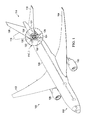
Figure 1 , an illustration of an aircraft is depicted in accordance with an illustrative embodiment. In this illustrative example,aircraft 100 haswing 102 andwing 104 attached tofuselage 106.Aircraft 100 includesengine 108 attached towing 102 andengine 110 attached towing 104. -
Fuselage 106 hasnose section 112 andtail section 114.Horizontal stabilizer 116,horizontal stabilizer 118, andvertical stabilizer 120 are attached totail section 114 offuselage 106. -
Aircraft 100 is an example of an aircraft in which a lavatory access system may be implemented in accordance with an illustrative embodiment. As depicted,section 121 illustrates an exposed view in whichinterior 122 ofpassenger cabin 124 infuselage 106 ofaircraft 100 is seen. In this illustrative example,section 121 ofpassenger cabin 124 includeslavatory area 126 as seen in this exposed view. - In this illustrative example,
lavatory area 126 includesfirst lavatory 128 andsecond lavatory 130. These lavatories are examples of lavatories that may be reconfigured to allow greater access to handicapped passengers in accordance with an illustrative embodiment. In particular, these lavatories may be reconfigured without changingperimeter 132 forfirst lavatory 128 andsecond lavatory 130. In other words,perimeter 132 remains fixed in these illustrative examples. - With reference now to
Figure 2 , an illustration of a block diagram of a platform with a lavatory area is depicted in accordance with an illustrative embodiment. In this depicted example,platform 200 may beaircraft 202.Aircraft 100 inFigure 1 is an example of one physical implementation foraircraft 202 shown in block form in this figure. - As depicted,
platform 200 includeslavatory area 204.Lavatory area 204 is an area withinplatform 200 in whichfirst lavatory 206 andsecond lavatory 208 may be located. In this illustrative example,first lavatory 206 andsecond lavatory 208 are adjacent to each other. -
Perimeter 210 is a boundary aroundfirst lavatory 206 andsecond lavatory 208. In this illustrative example,perimeter 210 takes the form of fixedperimeter 212 that extends aroundfirst lavatory 206 andsecond lavatory 208. As depicted,perimeter 210 is fixedperimeter 212 becausewalls 214 formingperimeter 210 aroundfirst lavatory 206 andsecond lavatory 208 are fixed and do not move into other areas withinlavatory area 204 or other areas withinplatform 200. - In this illustrative example,
first lavatory 206 includesfirst wash basin 216 andfirst toilet 218.Second lavatory 208 includessecond wash basin 220 andsecond toilet 222. Additionally,first lavatory 206 hasfirst door 224 andsecond lavatory 208 hassecond door 226 located withinwalls 214. - As depicted,
moveable partition 228 is present inlavatory area 204 and forms at least part ofwall 230 betweenfirst lavatory 206 andsecond lavatory 208.Moveable partition 228 is a structure that may be used to reconfigure space forfirst lavatory 206 andsecond lavatory 208 withinwalls 214. -
Moveable partition 228 may be comprised of different types of materials. For example,moveable partition 228 may be comprised of a composite material, a metal, or some other suitable type of material. -
Moveable partition 228 may havefirst configuration 232 andsecond configuration 234. In particular,moveable partition 228 may be moved betweenfirst configuration 232 andsecond configuration 234. - In these illustrative examples, when
moveable partition 228 is infirst configuration 232,moveable partition 228 forms at least a portion ofwall 230. Infirst configuration 232,moveable partition 228 is configured to separatefirst lavatory 206 andsecond lavatory 208 intospaces 236. In particular,spaces 236 includefirst space 238 andsecond space 240.First space 238 is space withinfirst lavatory 206 inperimeter 210.Second space 240 is space withinsecond lavatory 208 inperimeter 210. - When
moveable partition 228 is insecond configuration 234,moveable partition 228 definessingle space 242 forfirst lavatory 206 andsecond lavatory 208 instead ofspaces 236.Single space 242 may provide additional room for passengers such as a family, a handicapped passenger, or other types of passengers who may require additional room withinlavatory area 204. - In these illustrative examples,
moveable partition 228 may be connected tofirst door 224 forfirst lavatory 206 whenmoveable partition 228 is insecond configuration 234. As used herein, a first component,moveable partition 228, "connected to" a second component,first door 224, means that the first component can be connected directly or indirectly to the second component. In other words, additional components may be present between the first component and the second component. The first component is considered to be indirectly connected to the second component when one or more additional components are present between the two components. When the first component is directly connected to the second component, no additional components are present between the two components. - In this illustrative example,
moveable partition 228 may be connected tofirst door 224 byconnector system 246. In particular,connector system 246 may be, for example, a latch. Further, the latch may be a magnetic latch. -
Hinge system 244 is associated withfirst door 224 andmoveable partition 228.Hinge system 244 is configured to allowmoveable partition 228 to rotate into a position againstfirst door 224.Hinge system 244 also may allowmoveable partition 228 to fold whenmoveable partition 228 is comprised ofsections 248. In this particular example,moveable partition 228 is configured to be folded againstfirst door 224 whenmoveable partition 228 is insecond configuration 234. - The illustration of
platform 200 andlavatory area 204 inplatform 200 is not meant to imply physical or architectural limitations to the manner in which an illustrative embodiment may be implemented. Other components in addition to or in place of the ones illustrated may be used. Some components may be unnecessary. Also, the blocks are presented to illustrate some functional components. One or more of these blocks may be combined, divided, or combined and divided into different blocks when implemented in an illustrative embodiment. - For example, although
platform 200 has been described as being implemented asaircraft 202,platform 200 may be implemented in other forms.Platform 200 may be, for example, a mobile platform, a stationary platform, a land-based structure, an aquatic-based structure, and a space-based structure. More specifically,platform 200 may be a surface ship, a train, a spacecraft, a space station, a submarine, a power plant, a house, an office, a manufacturing facility, a building, and other suitable platforms. - In another illustrative example, a third lavatory may be adjacent to one of
first lavatory 206 andsecond lavatory 208. The common wall between the third lavatory and the other lavatory may also be formed using another moveable partition similar tomoveable partition 228. In other illustrative examples, both common walls of the middle lavatory may be moveable partitions such that an even larger space is available if desired. - With reference now to
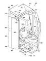
Figure 3 , an illustration of a lavatory area in an aircraft is depicted in accordance with an illustrative embodiment. In this depicted example, a more detailed illustration ofsection 121 infuselage 106 ofaircraft 100 is shown. Some components forfirst lavatory 128 andsecond lavatory 130 can be seen in this exposed view oflavatory area 126. In particular,first lavatory 128 andsecond lavatory 130 are examples of physical implementations forfirst lavatory 206 andsecond lavatory 208 inFigure 2 . - As depicted,
first lavatory 128 includesfirst toilet 300 andsecond lavatory 130 includessecond toilet 302. As can be seen in this illustrative example,first space 304 andsecond space 306 are located withinperimeter 132.First space 304 andsecond space 306 are defined byperimeter 132 and guide 308. - In these illustrative examples, instead of placing a wall along
guide 308, a moveable partition (not shown), such asmoveable partition 228 shown in block form inFigure 2 may be placed alongguide 308. With the use of an illustrative embodiment,first space 304 andsecond space 306 withinperimeter 132 may be combined to formsingle space 310. - With reference now to
Figure 4 , an illustration of a plan view of a first lavatory and a second lavatory within a lavatory area is depicted in accordance with an illustrative embodiment. A plan view offirst lavatory 128 andsecond lavatory 130 is shown in this figure. - In this view,
first wash basin 400 is shown infirst lavatory 128. Additionally,second wash basin 402 is shown insecond lavatory 130. - As can be seen in this plan view,
walls 404 defineperimeter 132.Perimeter 132 definesfirst space 304 andsecond space 306 forfirst lavatory 128 andsecond lavatory 130. In this illustrative example,first space 304 andsecond space 306 may be defined withinperimeter 132 bymoveable partition 406. - As depicted,
first door 408 is a first door forfirst lavatory 128.First door 408 is located infirst opening 410 inwalls 404.Second door 412 is a door forsecond lavatory 130.Second door 412 is located insecond opening 414 inwalls 404. - As depicted,
moveable partition 406 hasfirst end 416 andsecond end 418. In this illustrative example,moveable partition 406 is comprised offirst section 422 andsecond section 424.First end 416 ofmoveable partition 406 is connected tofirst door 408 byhinge system 425 in these illustrative examples. - As depicted,
moveable partition 406 hasfirst configuration 420 whenmoveable partition 406 definesfirst space 304 forfirst lavatory 128 andsecond space 306 forsecond lavatory 130 withinperimeter 132. -
Moveable partition 406 may be placed intosecond configuration 426.Moveable partition 406 is shown in phantom in an intermediate position during its movement to thesecond configuration 426. Insecond configuration 426,moveable partition 406 may be folded againstside 428 offirst door 408. Bothfirst door 408 andmoveable partition 406 may be rotated aboutcommon axis 430 in the direction ofarrow 432. - When
moveable partition 406 is insecond configuration 426,first lavatory 128 andsecond lavatory 130 are no longer divided intofirst space 304 andsecond space 306. Instead,first space 304 andsecond space 306 are combined to formsingle space 310. -
Figures 5-10 are illustrations of a reconfiguration of space forfirst lavatory 128 andsecond lavatory 130 usingmoveable partition 406 in accordance with an illustrative embodiment. These figures illustrate different configurations formoveable partition 406 used to divide and combine space withinfirst lavatory 128 andsecond lavatory 130. - Turning now to
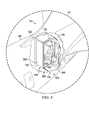
Figure 5 , an illustration of an isometric view of a first lavatory and a second lavatory in a lavatory area is depicted in accordance with an illustrative embodiment. In this depicted example, an isometric view oflavatory area 126 withfirst lavatory 128 andsecond lavatory 130 is shown. - In this view,
first door 408 is shown in phantom to provide a better view offirst space 304 infirst lavatory 128. Further,moveable partition 406 is shown infirst configuration 420. As can be seen,moveable partition 406 definesfirst space 304 andsecond space 306. In this configuration,first lavatory 128 andsecond lavatory 130 may be used by different passengers. This configuration of space forfirst lavatory 128 andsecond lavatory 130 may be considered a normal configuration of space for these two lavatories. - Further, in this view,
divider 500 is present.Divider 500 is located adjacent to at least one offirst toilet 300 andsecond toilet 302. In this illustrative example,divider 500 is located betweenfirst toilet 300 andsecond toilet 302.Divider 500 is configured to move. In particular,divider 500 is rotatable and may be configured to rotate in the direction ofarrow 502 towardwall 504. In this example,wall 504 is a fuselage wall. - Turning now to
Figure 6 , an illustration of movement of a moveable partition is depicted in accordance with an illustrative embodiment. In this illustration,moveable partition 406 begins moving out offirst configuration 420. - As can be seen,
moveable partition 406 begins rotating in the direction ofarrow 432 aboutcommon axis 430.Hinge 602 inhinge system 425 provides for this movement. Additionally,first section 422 andsecond section 424 fold relative to each other throughhinge 604 inhinge system 425. - In
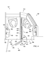
Figure 7 , an illustration of movement of a moveable partition is depicted in accordance with an illustrative embodiment. In this figure,first section 422 andsection 424 ofmoveable partition 406 are folded against each other. Additionally,moveable partition 406 is shown as having rotated further aboutcommon axis 430 in the direction ofarrow 432. - Next,
Figure 8 is an illustration of movement of a moveable partition in accordance with an illustrative embodiment. In this illustration,moveable partition 406 is in foldedposition 800 againstfirst door 408. Whenmoveable partition 406 is in foldedposition 800 againstfirst door 408,moveable partition 406 is connected tofirst door 408. This connection may be made through a connector system (not shown). Additionally,divider 500 has been rotated towardwall 504 in the direction ofarrow 502. - In this illustrative example,
moveable partition 406 is insecond configuration 426 againstfirst door 408. Of course,moveable partition 406 may be considered to be insecond configuration 426 whenevermoveable partition 406 has been moved such that bothfirst space 304 andsecond space 306 may be used assingle space 310. - Turning now to
Figure 9 , an illustration of movement of a moveable partition is depicted in accordance with an illustrative embodiment. In this view,first door 408 is shown rotated in the direction ofarrow 432 aboutcommon axis 430. Additionally,moveable partition 406 also rotates withfirst door 408 in the direction ofarrow 432 aboutcommon axis 430. - Turning now to
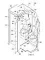
Figure 10 , an illustration of a first lavatory and a second lavatory in a lavatory area reconfigured for use with a single space is depicted in accordance with an illustrative embodiment. In this illustrative example,first lavatory 128 andsecond lavatory 130 are configured to providesingle space 310 withinperimeter 132 forpassenger 1000 located inwheelchair 1002. - As can be seen in this example,
moveable partition 406 is in foldedposition 800 againstside 428 offirst door 408. Additionally,divider 500 has been rotated towardswall 504 inwalls 404 to provide increased access to at least one offirst toilet 300 infirst lavatory 128 andsecond toilet 302 insecond lavatory 130 as well as possibly other components for these two lavatories. - The illustration of
first lavatory 128 andsecond lavatory 130 withmoveable partition 406 inFigure 1 andFigures 3 -10 is not meant to imply limitations to the manner in which other lavatories may be implemented with moveable partitions. For example, a moveable partition may have one or more additional sections in addition tofirst section 422 andsecond section 424 in other illustrative examples. - With reference now to
Figure 11 , an illustration of a more detailed view of a hinge connection for a moveable partition is depicted in accordance with an illustrative embodiment. In this illustrative example, a more detailed illustration ofhinge 602 is shown. As can be seen,section 1100 ofhinge 602 is connected tofirst end 416 offirst section 422 inmoveable partition 406. - Turning now to
Figure 12 , an illustration of movement for a hinge connection for a moveable partition is depicted in accordance with an illustrative embodiment. In this view,moveable partition 406 has been rotated againstfirst door 408. As can be seen,section 1100 is configured to allowmoveable partition 406 to move againstfirst door 408 such thatmoveable partition 406 andfirst door 408 are substantially parallel to each other. - Turning now to
Figure 13 , another illustration of movement for a hinge connection for a moveable partition is depicted in accordance with an illustrative embodiment. In this illustration,first door 408 has been opened to allow entry throughfirst opening 410. As can be seen,moveable partition 406 is in foldedposition 800 againstside 428 offirst door 408. In this illustrative example,first door 408 andmoveable partition 406 have rotated aboutcommon axis 430 in the direction ofarrow 432. - The illustration of
hinge system 425 illustrated inFigures 11-13 are only examples of one implementation ofhinge system 244 shown in block form inFigure 2 . Of course, other types of hinges and other numbers of hinges may be used other than those shown in these figures. - Turning now to
Figure 14 , an illustration of a connector system for a moveable partition is depicted in accordance with an illustrative embodiment. In this illustrative example,connector system 1400 is an example of one implementation forconnector system 246 shown in block form inFigure 2 .Connector system 1400 may be a magnetic connector system in these illustrative examples. - In this figure, only
first door 408,moveable partition 406, andhinge system 425 are shown. The other components inlavatory area 126 inFigure 1 are not shown in this figure for purposes of explainingconnector system 1400. - In this example,
connector system 1400 is comprised ofmagnetic connectors 1402. In this illustrative example,magnetic connectors 1402 comprisemagnetic connector -
Magnetic connector 1404 is located onside 428 offirst door 408.Magnetic connector 1406 is located onfirst side 1412 offirst section 422 ofmoveable partition 406.Magnetic connector 1408 is shown in phantom.Magnetic connector 1408 is located onsecond side 1414 offirst section 422 ofmoveable partition 406.Magnetic connector 1410 is shown in phantom and is located onsecond side 1416 opposite offirst side 1418 ofsecond section 424 ofmoveable partition 406. - When
first section 422 andsecond section 424 are folded against each other,magnetic connector 1408 onsecond side 1414 offirst section 422 andmagnetic connector 1410 onsecond side 1416 ofsecond section 424 are configured to contact each other.Magnetic connector 1408 andmagnetic connector 1410 are configured to hold these two sections against each other when these two magnetic connectors contact each other. - When
first section 422 is rotated againstside 428 offirst door 408,magnetic connector 1404 onside 428 offirst door 408 is configured to contactmagnetic connector 1406 offirst side 1412 offirst section 422 inmoveable partition 406.Magnetic connector 1404 andmagnetic connector 1406 connect to each other to holdmoveable partition 406 againstside 428 offirst door 408. As depicted,magnetic connector 1404 andmagnetic connector 1406 inconnector system 1400 are configured to holdmoveable partition 406 in foldedposition 800 againstfirst door 408 as shown inFigure 10 . - The illustration of
connector system 1400 is only presented as one illustrative example of a physical implementation forconnector system 246 inFigure 2 . Other implementations may use other configurations of magnetic connectors and other types of connectors in addition to or in place of the magnetic connectors. For example, latches may be used for the connector system in some implementations. - The different components shown in
Figure 1 andFigures 3 -14 may be combined with components inFigure 2 , used with components inFigure 2 , or a combination of the two. Additionally, some of the components inFigure 1 andFigures 3 -14 may be illustrative examples of how components shown in block form inFigure 2 can be implemented as physical structures. - Turning now to
Figure 15 , an illustration of a flowchart of a process for reconfiguring lavatory space in an aircraft is depicted in accordance with an illustrative embodiment. The process inFigure 15 may be implemented infirst lavatory 128 andsecond lavatory 130 usingmoveable partition 228 inFigure 2 . - The process begins by operating an aircraft in which a first lavatory and a second lavatory are located in the aircraft with a moveable partition (operation 1500). The moveable partition is for the first lavatory and a second lavatory. The moveable partition moved for the first lavatory and the second lavatory is moved between a first configuration and a second configuration (operation 1502) with the process terminating thereafter. The first configuration of the moveable partition separates the first lavatory and the second lavatory into separate spaces within a fixed perimeter for the first lavatory and the second lavatory. The second configuration for the moveable partition has a single space present within the fixed perimeter and the moveable partition is connected to a door for the first lavatory in the second configuration.
- The flowcharts and block diagrams in the different depicted embodiments illustrate the architecture, functionality, and operation of some possible implementations of apparatuses and methods in an illustrative embodiment. In this regard, each block in the flowcharts or block diagrams may represent a module, a segment, a function, and/or a portion of an operation or step. For example, one or more of the blocks may be implemented as program code, in hardware, or a combination of the program code and hardware. When implemented in hardware, the hardware may, for example, take the form of integrated circuits that are manufactured or configured to perform one or more operations in the flowcharts or block diagrams.
- For example,
operation 1502 may be implemented using a hardware system that is configured to change the configuration of a moveable partition based on an input from a human operator if lavatories are unoccupied. For example, a human operator may push one button for the first configuration and a second button for the second configuration. In another illustrative example, the hardware may detect the presence of a wheelchair and automatically change the configuration of the moveable partition if both lavatories are unoccupied. - In some alternative implementations of an illustrative embodiment, the function or functions noted in the blocks may occur out of the order noted in the figures. For example, in some cases, two blocks shown in succession may be executed substantially concurrently, or the blocks may sometimes be performed in the reverse order, depending upon the functionality involved. Also, other blocks may be added in addition to the illustrated blocks in a flowchart or block diagram.
- Illustrative embodiments of the disclosure may be described in the context of aircraft manufacturing and
service method 1600 as shown inFigure 16 andaircraft 1700 as shown inFigure 17 . Modifications or redesign oflavatory area 126 inFigure 1 may occur during the process of aircraft manufacturing andservice method 1600 inaircraft 1700 in these illustrative examples. - Turning first to
Figure 16 , an illustration of an aircraft manufacturing and service method is depicted in accordance with an illustrative embodiment. During pre-production, aircraft manufacturing andservice method 1600 may include specification anddesign 1602 ofaircraft 1700 inFigure 17 andmaterial procurement 1604. - During production, component and
subassembly manufacturing 1606 andsystem integration 1608 ofaircraft 1700 inFigure 17 takes place. Thereafter,aircraft 1700 inFigure 17 may go through certification anddelivery 1610 in order to be placed inservice 1612. While inservice 1612 by a customer,aircraft 1700 inFigure 17 is scheduled for routine maintenance andservice 1614, which may include modification, reconfiguration, refurbishment, and other maintenance or service. - Each of the processes of aircraft manufacturing and
service method 1600 may be performed or carried out by a system integrator, a third party, and/or an operator. In these examples, the operator may be a customer. For the purposes of this description, a system integrator may include, without limitation, any number of aircraft manufacturers and major-system subcontractors; a third party may include, without limitation, any number of vendors, subcontractors, and suppliers; and an operator may be an airline, a leasing company, a military entity, a service organization, and so on. - With reference now to
Figure 17 , an illustration of an aircraft is depicted in which an illustrative embodiment may be implemented.Aircraft 1700 may be one example ofaircraft 100 inFigure 1 oraircraft 202 inFigure 2 . - In this example,
aircraft 1700 is produced by aircraft manufacturing andservice method 1600 inFigure 16 and may includeairframe 1702 with plurality ofsystems 1704 and interior 1706. Examples ofsystems 1704 include one or more ofpropulsion system 1708,electrical system 1710,hydraulic system 1712, andenvironmental system 1714. Any number of other systems may be included. Although an aerospace example is shown, different illustrative embodiments may be applied to other industries, such as the automotive industry. - Apparatuses and methods embodied herein may be employed during at least one of the stages of aircraft manufacturing and
service method 1600 inFigure 16 . One or more illustrative embodiments may be designed during specification anddesign 1602 in stages of aircraft manufacturing andservice method 1600. For example, a first lavatory and a second lavatory may be designed with a perimeter that employs a moveable partition. The different components for the first lavatory and the second lavatory with a moveable partition may be manufactured during component andsubassembly manufacturing 1606. These components may be installed duringsystem integration 1608. - Further, in some illustrative examples, an illustrative embodiment may be implemented during maintenance and
service 1614. For example, a moveable partition may be installed as part of maintenance, upgrade, or refurbishment between a first lavatory and a second lavatory. Further, the aircraft may be configured such that a first lavatory and a second lavatory are adjacent to each other with a common perimeter. - Further, the illustrative embodiments may be used during in
service 1612 to reconfigure a first lavatory and a second lavatory to provide a first space and a second space that are divided from each other, or a single space. - In this manner, one or more of the illustrative embodiments may provide increased flexibility and access to lavatories in an aircraft. This increased access may be provided to passengers who may need more space than provided by a standard lavatory. These passengers may be handicapped passengers, larger-sized passengers, or other passengers who may need more room that normally provided by a normal lavatory in
aircraft 1700. - Further, the illustrative embodiments allow reconfiguration of a first lavatory and a second lavatory as needed during in
service 1612 and, in particular, during the flight ofaircraft 1700. Moreover, one or more of the illustrative embodiments provide for additional usable space when the first lavatory and the second lavatory are configured to provide a single space within the perimeter of these lavatories. - The description of the different illustrative embodiments has been presented for purposes of illustration and description, and is not intended to be exhaustive or limited to the embodiments in the form disclosed. Many modifications and variations will be apparent to those of ordinary skill in the art. Although access is described as being provided for handicapped passengers, the reconfiguration of a first lavatory and a second lavatory to provide more space may be performed for other passengers. For example, the reconfiguration using the moveable partition may be performed for families or parents with small children.
- Further, different illustrative embodiments may provide different features as compared to other illustrative embodiments. The embodiment or embodiments selected are chosen and described in order to best explain the principles of the embodiments, the practical application, and to enable others of ordinary skill in the art to understand the disclosure for various embodiments with various modifications as are suited to the particular use contemplated.
- According to an aspect of the present disclosure there is provided a method of operating an aircraft, the method comprising: operating the aircraft in which a first lavatory and a second lavatory are located in the aircraft with a moveable partition configured for use with the first lavatory and the second lavatory, wherein the moveable partition is configured to separate the first lavatory and the second lavatory into separate spaces within a fixed perimeter for the first lavatory and the second lavatory when the moveable partition is in a first configuration and wherein the moveable partition is configured to define a single space within the fixed perimeter when the moveable partition is in a second configuration, wherein the moveable partition is connected to a door for the first lavatory in the second configuration. Advantageously, the first lavatory includes a first toilet and a first wash basin and the second lavatory includes a second toilet and a second wash basin and wherein the first toilet, the first wash basin, the second toilet, and the second wash basin are unobstructed by the moveable partition in the second configuration.
- In accordance with an aspect of the present disclosure, the movable partition and the divider are adjacent when the moveable partition is in its first configuration and are spaced apart when the moveable partition is in its second configuration, so as to provide increased access to components of the first and second lavatories. The divider may be arranged to move in a substantially opposite direction from the moveable partition when the partition is moved from its first to its second configuration. Although the divider is shown here to be rotatable about a lying axis, other types of movement are also conceivable, like e.g. a slideable divider. When the moveable partition is foldable, it may include a plurality of sections which are mutually connected by hinges. In accordance with an aspect of this disclosure, the hinge system connecting the moveable partition to the door may be configured for a rotating movement through an arc of at least 135 degrees, preferably at least 150 degrees and more preferably at least 180 degrees. This allows the partition to first move to a position parallel to the first lavatory door, defining the second configuration, and then move with the door when this is opened to provide access to the single space formed by the two lavatories.
Claims (15)
- An apparatus comprising:a moveable partition configured for use with a first lavatory and a second lavatory, wherein the moveable partition is configured to separate the first lavatory and the second lavatory into separate spaces within a fixed perimeter for the first lavatory and the second lavatory when the moveable partition is in a first configuration and wherein the moveable partition is configured to define a single space within the fixed perimeter when the moveable partition is in a second configuration, wherein the moveable partition is connected to a door for the first lavatory in the second configuration.
- The apparatus of claim 1, wherein the first lavatory includes a first toilet and a first wash basin and the second lavatory includes a second toilet and a second wash basin and wherein the first toilet, the first wash basin, the second toilet, and the second wash basin are unobstructed by the moveable partition in the second configuration.
- The apparatus of claims 1 or 2 further comprising:a hinge system connecting the moveable partition to the door.
- The apparatus of claims 1-3, wherein the moveable partition and the door are configured to rotate about a common axis.
- The apparatus of claims 1-4, wherein the moveable partition is foldable and configured to be folded against the door in the second configuration.
- The apparatus of claims 1-5 further comprising:a connector system configured to hold the moveable partition in a folded position against the door.
- The apparatus of claim 2 further comprising:a divider adjacent to at least one of the first toilet and the second toilet, wherein the divider is configured to move.
- The apparatus of claim 7, wherein the first lavatory includes the first toilet and the second lavatory includes the second toilet and wherein rotation of the divider towards the wall increases accessibility to at least one of the first toilet and the second toilet.
- A method for reconfiguring lavatory space in an aircraft, the method comprising:moving a moveable partition for a first lavatory and a second lavatory between a first configuration and a second configuration, wherein the first configuration separates the first lavatory and the second lavatory into
separate spaces within a fixed perimeter for the first lavatory and the second lavatory, and wherein the second configuration has a single space present within the fixed perimeter and the moveable partition is connected to a door for the first lavatory in the second configuration. - The method of claim 9, wherein the first lavatory includes a first toilet and a first wash basin and the second lavatory includes a second toilet and a second wash basin and wherein the first toilet, the first wash basin, the second toilet, and the second wash basin are unobstructed by the moveable partition in the second configuration.
- The method of claims 9 or 10, wherein a hinge system connects the moveable partition to the door.
- The method of claims 9-11, wherein the moveable partition and the door are configured to rotate about a common axis.
- The method of claims 9-12 further comprising:a connector system configured to hold the moveable partition in a folded position against the door.
- The method of claim 13, wherein the connector system is a magnetic connector system.
- The method of claims 9-14, wherein the first lavatory includes a first toilet and the second lavatory includes a second toilet and wherein a divider is located adjacent to at least one of the first toilet and the second toilet, wherein the divider is configured to rotate towards a wall and rotation of the divider towards the wall increases accessibility to at least one of the first toilet and the second toilet.
Applications Claiming Priority (1)
| Application Number | Priority Date | Filing Date | Title |
|---|---|---|---|
| US13/621,462 US9308997B2 (en) | 2012-09-17 | 2012-09-17 | Lavatory reconfiguration system |
Publications (3)
| Publication Number | Publication Date |
|---|---|
| EP2708467A2 true EP2708467A2 (en) | 2014-03-19 |
| EP2708467A3 EP2708467A3 (en) | 2017-11-01 |
| EP2708467B1 EP2708467B1 (en) | 2018-11-21 |
Family
ID=49226017
Family Applications (1)
| Application Number | Title | Priority Date | Filing Date |
|---|---|---|---|
| EP13184546.3A Active EP2708467B1 (en) | 2012-09-17 | 2013-09-16 | Lavatory reconfiguration system |
Country Status (2)
| Country | Link |
|---|---|
| US (1) | US9308997B2 (en) |
| EP (1) | EP2708467B1 (en) |
Cited By (3)
| Publication number | Priority date | Publication date | Assignee | Title |
|---|---|---|---|---|
| EP3056428A1 (en) * | 2015-02-12 | 2016-08-17 | The Boeing Company | Aft rest area assembly within an aircraft cabin |
| WO2018002308A3 (en) * | 2016-06-30 | 2018-02-22 | Cathay Pacific Airways Limited | Cabin module and layout for a passenger aircraft |
| EP2873616B1 (en) * | 2013-11-15 | 2019-10-30 | Airbus Operations GmbH | Toilet arrangement for a vehicle |
Families Citing this family (17)
| Publication number | Priority date | Publication date | Assignee | Title |
|---|---|---|---|---|
| JP2014076713A (en) * | 2012-10-10 | 2014-05-01 | Yokohama Rubber Co Ltd:The | Aircraft toilet unit |
| US9051052B2 (en) * | 2012-10-26 | 2015-06-09 | The Boeing Company | Single aisle aircraft lavatory with optimized use of floor space for wheelchair accessibility |
| US9045231B2 (en) | 2012-11-05 | 2015-06-02 | C&D Zodiac, Inc. | Wheelchair accessible lavatory |
| US9359076B2 (en) * | 2013-02-11 | 2016-06-07 | B/E Aerospace, Inc. | Compact aircraft galley and lavatory arrangement and articulating lavatory partition for an aircraft |
| US8944377B2 (en) | 2013-06-11 | 2015-02-03 | The Boeing Company | Lavatory reconfiguration system |
| US9688407B2 (en) * | 2013-10-03 | 2017-06-27 | The Boeing Company | Modular lavatory system |
| FR3036098B1 (en) * | 2015-05-12 | 2017-05-12 | Airbus Operations Sas | FOLDING WALL ACCESS DEVICE FOR SECURE COMMUNICATION BETWEEN AT LEAST TWO ZONES OF AN ENCLOSURE |
| DE102015211813A1 (en) * | 2015-06-25 | 2016-12-29 | Airbus Operations Gmbh | Sanitary module with folding niche for an airplane and aircraft door area |
| FR3055128A1 (en) * | 2016-08-17 | 2018-02-23 | Zodiac Seats France | ARRANGEMENT OF SEATS FOR INCREASING THE INTIMACY OF PASSENGERS, IN PARTICULAR AN AIRCRAFT |
| HUE057898T2 (en) * | 2016-10-07 | 2022-06-28 | Be Aerospace Inc | Aircraft modular lavatory system |
| EP3697688B1 (en) * | 2017-10-17 | 2023-03-29 | Airbus Canada Managing GP Inc. | Lavatory enclosure reconfigurable to accommodate a stretcher |
| US11542007B2 (en) | 2017-12-21 | 2023-01-03 | Airbus Operations Gmbh | Dual configuration lavatory with assist space |
| US11370548B2 (en) | 2018-05-02 | 2022-06-28 | B/E Aerospace, Inc. | Aft complex galley and lavatory arrangement |
| WO2019213136A1 (en) * | 2018-05-02 | 2019-11-07 | B/E Aerospace, Inc. | Modular lavatory accessible to passengers of reduced mobility (prm) |
| GB2578096B (en) * | 2018-10-15 | 2022-11-09 | Safran Seats Gb Ltd | Aircraft passenger seat unit |
| WO2020092325A1 (en) * | 2018-10-30 | 2020-05-07 | Safran Cabin Inc. | Aft complex with prm lavatory |
| US11958609B2 (en) * | 2022-05-04 | 2024-04-16 | The Boeing Company | Expandable aircraft lavatory apparatus, system, and method |
Family Cites Families (38)
| Publication number | Priority date | Publication date | Assignee | Title |
|---|---|---|---|---|
| US3541750A (en) | 1969-06-04 | 1970-11-24 | Avco Corp | Expandable rooms incorporating building construction |
| US3862525A (en) | 1970-07-24 | 1975-01-28 | Donald J Greenspan | Medical office facility with two or more examining rooms having a common equipment core area |
| US4100857A (en) * | 1977-04-11 | 1978-07-18 | Pullman Incorporated | Passageway between adjacent railway passenger car compartments |
| US4589463A (en) | 1984-09-28 | 1986-05-20 | Falcon Jet Corporation | Expandable volume lavatory |
| US4672772A (en) | 1986-09-19 | 1987-06-16 | Ichiro Nakamura | Balanced door for airplane lavatories and the like |
| JPH03202562A (en) * | 1989-12-29 | 1991-09-04 | Takenaka Komuten Co Ltd | Variable bathroom unit |
| JPH05163758A (en) * | 1991-12-17 | 1993-06-29 | Toto Ltd | Toilet equipment |
| CA2128041C (en) | 1994-07-14 | 1999-09-14 | Jacobus N. Hanemaayer | Combination swing and slide tri-fold door system for recreational vehicles or the like |
| JPH10121754A (en) * | 1996-10-24 | 1998-05-12 | Toto Ltd | Wheelchair dealing type toilet booth |
| US6007025A (en) * | 1996-12-23 | 1999-12-28 | The Boeing Company | Stowable module airplane lavatory |
| US6079669A (en) * | 1997-03-24 | 2000-06-27 | The Boeing Company | Dual pivot expandable lavatory |
| US6186444B1 (en) | 1999-01-15 | 2001-02-13 | Charles F. Steel | Sliding pocket door for aircraft use capable of nondestructive blow-out and easy access |
| JP2001098773A (en) * | 1999-09-30 | 2001-04-10 | Daiwa House Ind Co Ltd | Enlarged toilet room structure |
| US6257523B1 (en) | 1999-12-09 | 2001-07-10 | The Boeing Company | Foldable partition with integral door |
| JP3573707B2 (en) * | 2000-11-22 | 2004-10-06 | 株式会社ジャムコ | Expandable lavatory unit for aircraft |
| US6702231B2 (en) | 2001-10-10 | 2004-03-09 | Gary Ward | Door system for creating and maintaining a secured area |
| WO2003057563A1 (en) | 2002-01-09 | 2003-07-17 | Crupax Security Inc. | Flight deck security system |
| DE10204343A1 (en) | 2002-02-01 | 2003-08-07 | Wall Ag | toilet facility |
| US6604709B1 (en) * | 2002-02-20 | 2003-08-12 | The Boeing Company | Dot (department of transportation) lavatory and shower combination |
| US7222820B2 (en) | 2003-02-25 | 2007-05-29 | The Boeing Company | Aircraft lavatory |
| US6823927B2 (en) | 2003-03-05 | 2004-11-30 | Charles F. Steel | Pocket door with pivoting panel |
| JP4155860B2 (en) | 2003-04-16 | 2008-09-24 | ブランデ株式会社 | Security door device |
| DE10339077A1 (en) * | 2003-08-26 | 2005-03-31 | Airbus Deutschland Gmbh | Passenger compartment in the cabin of a commercial airplane |
| US6889936B1 (en) | 2003-11-17 | 2005-05-10 | The Boeing Company | Apparatus and methods for increasing useable space within aircraft lavatories |
| US7299511B2 (en) | 2004-04-29 | 2007-11-27 | The Boeing Company | Stand up lavatory module |
| CA2576760C (en) | 2004-08-03 | 2013-09-10 | Airbus | Door for closing an opening inside an aircraft |
| WO2006024725A1 (en) | 2004-08-03 | 2006-03-09 | Airbus | Safety inside door for an aircraft |
| US7721990B2 (en) | 2005-07-29 | 2010-05-25 | Airbus Deutschland Gmbh | Passenger compartment |
| US7950439B2 (en) | 2005-11-28 | 2011-05-31 | Victor Ray Anderson | Combination-action slide and hinge swinging door |
| US7866603B2 (en) | 2007-04-27 | 2011-01-11 | The Boeing Company | Methods and apparatus for an aircraft lavoratory |
| US7984875B2 (en) | 2007-09-11 | 2011-07-26 | The Boeing Company | Multi-position secure door system |
| FR2941917B1 (en) | 2009-02-11 | 2012-08-31 | Airbus | MODULAR CLOSURE DEVICE FOR AN AIRCRAFT |
| JP5371500B2 (en) | 2009-03-17 | 2013-12-18 | 株式会社ジャムコ | Aircraft restroom door structure |
| US8621787B2 (en) | 2010-01-25 | 2014-01-07 | Ironstate Development, Llc | Prefabricated building modules for multi-unit housing |
| CN105923164B (en) | 2010-02-19 | 2018-03-27 | 空中客车德国运营有限责任公司 | Washing chamber device for the vehicles |
| US9708062B2 (en) | 2011-04-18 | 2017-07-18 | C Series Aircraft Limited Partnership | Aircraft lavatory for a person with reduced mobility |
| US20130206907A1 (en) | 2012-02-14 | 2013-08-15 | C&D Zodiac, Inc. | Expandable lavatory with movable wall |
| US8720827B2 (en) | 2012-09-25 | 2014-05-13 | The Boeing Company | Dual function lavatory door |
-
2012
- 2012-09-17 US US13/621,462 patent/US9308997B2/en active Active
-
2013
- 2013-09-16 EP EP13184546.3A patent/EP2708467B1/en active Active
Non-Patent Citations (1)
| Title |
|---|
| None |
Cited By (5)
| Publication number | Priority date | Publication date | Assignee | Title |
|---|---|---|---|---|
| EP2873616B1 (en) * | 2013-11-15 | 2019-10-30 | Airbus Operations GmbH | Toilet arrangement for a vehicle |
| EP3056428A1 (en) * | 2015-02-12 | 2016-08-17 | The Boeing Company | Aft rest area assembly within an aircraft cabin |
| US10583925B2 (en) | 2015-02-12 | 2020-03-10 | The Boeing Company | Aft rest area assembly within an aircraft cabin |
| WO2018002308A3 (en) * | 2016-06-30 | 2018-02-22 | Cathay Pacific Airways Limited | Cabin module and layout for a passenger aircraft |
| US11142320B2 (en) | 2016-06-30 | 2021-10-12 | Cathay Pacific Airways Limited | Cabin module and layout for a passenger aircraft |
Also Published As
| Publication number | Publication date |
|---|---|
| US20140077033A1 (en) | 2014-03-20 |
| EP2708467B1 (en) | 2018-11-21 |
| EP2708467A3 (en) | 2017-11-01 |
| US9308997B2 (en) | 2016-04-12 |
Similar Documents
| Publication | Publication Date | Title |
|---|---|---|
| EP2708467B1 (en) | Lavatory reconfiguration system | |
| EP2815974B1 (en) | Lavatory reconfiguration system | |
| EP3052383B1 (en) | Modular lavatory system | |
| EP3129281B1 (en) | Retaining system for a door element and method for locking and releasing a door element on board of an aircraft | |
| US7293739B2 (en) | Aircraft archway | |
| US8186760B2 (en) | Adjustable width seats | |
| JP6430454B2 (en) | Expandable door mounting seat | |
| EP2711295B1 (en) | Dual function lavatory door | |
| EP2803578A1 (en) | Expandable aircraft monument | |
| EP3873311B1 (en) | Aft complex with prm lavatory | |
| EP4108571A1 (en) | Redundant rail and carriage assembly | |
| CN106938702B (en) | Sliding closet | |
| EP4008635A1 (en) | Convertible aircraft cabin monument | |
| US11267550B2 (en) | Combined seat/stair arrangement for a multideck vehicle, in particular a multi-deck aircraft or spacecraft | |
| US11377215B1 (en) | Stowable flight attendant seat system | |
| EP2723637B1 (en) | Doorway width restriction system | |
| IT202100020024A1 (en) | MULTI-CONFIGURABLE AIRCRAFT STATION |
Legal Events
| Date | Code | Title | Description |
|---|---|---|---|
| PUAI | Public reference made under article 153(3) epc to a published international application that has entered the european phase |
Free format text: ORIGINAL CODE: 0009012 |
|
| 17P | Request for examination filed |
Effective date: 20130916 |
|
| AK | Designated contracting states |
Kind code of ref document: A2 Designated state(s): AL AT BE BG CH CY CZ DE DK EE ES FI FR GB GR HR HU IE IS IT LI LT LU LV MC MK MT NL NO PL PT RO RS SE SI SK SM TR |
|
| AX | Request for extension of the european patent |
Extension state: BA ME |
|
| RIN1 | Information on inventor provided before grant (corrected) |
Inventor name: NIX, JEFFREY Inventor name: SCOWN, STEPHEN LEE Inventor name: SPANE, MARC ANTON Inventor name: WILCYNSKI, PAUL JOSEPH |
|
| PUAL | Search report despatched |
Free format text: ORIGINAL CODE: 0009013 |
|
| AK | Designated contracting states |
Kind code of ref document: A3 Designated state(s): AL AT BE BG CH CY CZ DE DK EE ES FI FR GB GR HR HU IE IS IT LI LT LU LV MC MK MT NL NO PL PT RO RS SE SI SK SM TR |
|
| AX | Request for extension of the european patent |
Extension state: BA ME |
|
| RIC1 | Information provided on ipc code assigned before grant |
Ipc: B64D 11/02 20060101AFI20170922BHEP |
|
| GRAP | Despatch of communication of intention to grant a patent |
Free format text: ORIGINAL CODE: EPIDOSNIGR1 |
|
| STAA | Information on the status of an ep patent application or granted ep patent |
Free format text: STATUS: GRANT OF PATENT IS INTENDED |
|
| INTG | Intention to grant announced |
Effective date: 20180613 |
|
| GRAS | Grant fee paid |
Free format text: ORIGINAL CODE: EPIDOSNIGR3 |
|
| GRAA | (expected) grant |
Free format text: ORIGINAL CODE: 0009210 |
|
| STAA | Information on the status of an ep patent application or granted ep patent |
Free format text: STATUS: THE PATENT HAS BEEN GRANTED |
|
| AK | Designated contracting states |
Kind code of ref document: B1 Designated state(s): AL AT BE BG CH CY CZ DE DK EE ES FI FR GB GR HR HU IE IS IT LI LT LU LV MC MK MT NL NO PL PT RO RS SE SI SK SM TR |
|
| REG | Reference to a national code |
Ref country code: CH Ref legal event code: EP |
|
| REG | Reference to a national code |
Ref country code: IE Ref legal event code: FG4D |
|
| REG | Reference to a national code |
Ref country code: DE Ref legal event code: R096 Ref document number: 602013047017 Country of ref document: DE |
|
| REG | Reference to a national code |
Ref country code: AT Ref legal event code: REF Ref document number: 1067245 Country of ref document: AT Kind code of ref document: T Effective date: 20181215 |
|
| REG | Reference to a national code |
Ref country code: NL Ref legal event code: MP Effective date: 20181121 |
|
| REG | Reference to a national code |
Ref country code: AT Ref legal event code: MK05 Ref document number: 1067245 Country of ref document: AT Kind code of ref document: T Effective date: 20181121 |
|
| PG25 | Lapsed in a contracting state [announced via postgrant information from national office to epo] |
Ref country code: LV Free format text: LAPSE BECAUSE OF FAILURE TO SUBMIT A TRANSLATION OF THE DESCRIPTION OR TO PAY THE FEE WITHIN THE PRESCRIBED TIME-LIMIT Effective date: 20181121 Ref country code: HR Free format text: LAPSE BECAUSE OF FAILURE TO SUBMIT A TRANSLATION OF THE DESCRIPTION OR TO PAY THE FEE WITHIN THE PRESCRIBED TIME-LIMIT Effective date: 20181121 Ref country code: ES Free format text: LAPSE BECAUSE OF FAILURE TO SUBMIT A TRANSLATION OF THE DESCRIPTION OR TO PAY THE FEE WITHIN THE PRESCRIBED TIME-LIMIT Effective date: 20181121 Ref country code: BG Free format text: LAPSE BECAUSE OF FAILURE TO SUBMIT A TRANSLATION OF THE DESCRIPTION OR TO PAY THE FEE WITHIN THE PRESCRIBED TIME-LIMIT Effective date: 20190221 Ref country code: LT Free format text: LAPSE BECAUSE OF FAILURE TO SUBMIT A TRANSLATION OF THE DESCRIPTION OR TO PAY THE FEE WITHIN THE PRESCRIBED TIME-LIMIT Effective date: 20181121 Ref country code: FI Free format text: LAPSE BECAUSE OF FAILURE TO SUBMIT A TRANSLATION OF THE DESCRIPTION OR TO PAY THE FEE WITHIN THE PRESCRIBED TIME-LIMIT Effective date: 20181121 Ref country code: IS Free format text: LAPSE BECAUSE OF FAILURE TO SUBMIT A TRANSLATION OF THE DESCRIPTION OR TO PAY THE FEE WITHIN THE PRESCRIBED TIME-LIMIT Effective date: 20190321 Ref country code: NO Free format text: LAPSE BECAUSE OF FAILURE TO SUBMIT A TRANSLATION OF THE DESCRIPTION OR TO PAY THE FEE WITHIN THE PRESCRIBED TIME-LIMIT Effective date: 20190221 Ref country code: AT Free format text: LAPSE BECAUSE OF FAILURE TO SUBMIT A TRANSLATION OF THE DESCRIPTION OR TO PAY THE FEE WITHIN THE PRESCRIBED TIME-LIMIT Effective date: 20181121 |
|
| PG25 | Lapsed in a contracting state [announced via postgrant information from national office to epo] |
Ref country code: SE Free format text: LAPSE BECAUSE OF FAILURE TO SUBMIT A TRANSLATION OF THE DESCRIPTION OR TO PAY THE FEE WITHIN THE PRESCRIBED TIME-LIMIT Effective date: 20181121 Ref country code: NL Free format text: LAPSE BECAUSE OF FAILURE TO SUBMIT A TRANSLATION OF THE DESCRIPTION OR TO PAY THE FEE WITHIN THE PRESCRIBED TIME-LIMIT Effective date: 20181121 Ref country code: GR Free format text: LAPSE BECAUSE OF FAILURE TO SUBMIT A TRANSLATION OF THE DESCRIPTION OR TO PAY THE FEE WITHIN THE PRESCRIBED TIME-LIMIT Effective date: 20190222 Ref country code: AL Free format text: LAPSE BECAUSE OF FAILURE TO SUBMIT A TRANSLATION OF THE DESCRIPTION OR TO PAY THE FEE WITHIN THE PRESCRIBED TIME-LIMIT Effective date: 20181121 Ref country code: RS Free format text: LAPSE BECAUSE OF FAILURE TO SUBMIT A TRANSLATION OF THE DESCRIPTION OR TO PAY THE FEE WITHIN THE PRESCRIBED TIME-LIMIT Effective date: 20181121 Ref country code: PT Free format text: LAPSE BECAUSE OF FAILURE TO SUBMIT A TRANSLATION OF THE DESCRIPTION OR TO PAY THE FEE WITHIN THE PRESCRIBED TIME-LIMIT Effective date: 20190321 |
|
| PG25 | Lapsed in a contracting state [announced via postgrant information from national office to epo] |
Ref country code: DK Free format text: LAPSE BECAUSE OF FAILURE TO SUBMIT A TRANSLATION OF THE DESCRIPTION OR TO PAY THE FEE WITHIN THE PRESCRIBED TIME-LIMIT Effective date: 20181121 Ref country code: IT Free format text: LAPSE BECAUSE OF FAILURE TO SUBMIT A TRANSLATION OF THE DESCRIPTION OR TO PAY THE FEE WITHIN THE PRESCRIBED TIME-LIMIT Effective date: 20181121 Ref country code: CZ Free format text: LAPSE BECAUSE OF FAILURE TO SUBMIT A TRANSLATION OF THE DESCRIPTION OR TO PAY THE FEE WITHIN THE PRESCRIBED TIME-LIMIT Effective date: 20181121 Ref country code: PL Free format text: LAPSE BECAUSE OF FAILURE TO SUBMIT A TRANSLATION OF THE DESCRIPTION OR TO PAY THE FEE WITHIN THE PRESCRIBED TIME-LIMIT Effective date: 20181121 |
|
| REG | Reference to a national code |
Ref country code: DE Ref legal event code: R097 Ref document number: 602013047017 Country of ref document: DE |
|
| PG25 | Lapsed in a contracting state [announced via postgrant information from national office to epo] |
Ref country code: RO Free format text: LAPSE BECAUSE OF FAILURE TO SUBMIT A TRANSLATION OF THE DESCRIPTION OR TO PAY THE FEE WITHIN THE PRESCRIBED TIME-LIMIT Effective date: 20181121 Ref country code: SK Free format text: LAPSE BECAUSE OF FAILURE TO SUBMIT A TRANSLATION OF THE DESCRIPTION OR TO PAY THE FEE WITHIN THE PRESCRIBED TIME-LIMIT Effective date: 20181121 Ref country code: SM Free format text: LAPSE BECAUSE OF FAILURE TO SUBMIT A TRANSLATION OF THE DESCRIPTION OR TO PAY THE FEE WITHIN THE PRESCRIBED TIME-LIMIT Effective date: 20181121 Ref country code: EE Free format text: LAPSE BECAUSE OF FAILURE TO SUBMIT A TRANSLATION OF THE DESCRIPTION OR TO PAY THE FEE WITHIN THE PRESCRIBED TIME-LIMIT Effective date: 20181121 |
|
| PLBE | No opposition filed within time limit |
Free format text: ORIGINAL CODE: 0009261 |
|
| STAA | Information on the status of an ep patent application or granted ep patent |
Free format text: STATUS: NO OPPOSITION FILED WITHIN TIME LIMIT |
|
| 26N | No opposition filed |
Effective date: 20190822 |
|
| PG25 | Lapsed in a contracting state [announced via postgrant information from national office to epo] |
Ref country code: SI Free format text: LAPSE BECAUSE OF FAILURE TO SUBMIT A TRANSLATION OF THE DESCRIPTION OR TO PAY THE FEE WITHIN THE PRESCRIBED TIME-LIMIT Effective date: 20181121 |
|
| PG25 | Lapsed in a contracting state [announced via postgrant information from national office to epo] |
Ref country code: TR Free format text: LAPSE BECAUSE OF FAILURE TO SUBMIT A TRANSLATION OF THE DESCRIPTION OR TO PAY THE FEE WITHIN THE PRESCRIBED TIME-LIMIT Effective date: 20181121 |
|
| PG25 | Lapsed in a contracting state [announced via postgrant information from national office to epo] |
Ref country code: MC Free format text: LAPSE BECAUSE OF FAILURE TO SUBMIT A TRANSLATION OF THE DESCRIPTION OR TO PAY THE FEE WITHIN THE PRESCRIBED TIME-LIMIT Effective date: 20181121 |
|
| REG | Reference to a national code |
Ref country code: CH Ref legal event code: PL |
|
| PG25 | Lapsed in a contracting state [announced via postgrant information from national office to epo] |
Ref country code: LI Free format text: LAPSE BECAUSE OF NON-PAYMENT OF DUE FEES Effective date: 20190930 Ref country code: LU Free format text: LAPSE BECAUSE OF NON-PAYMENT OF DUE FEES Effective date: 20190916 Ref country code: CH Free format text: LAPSE BECAUSE OF NON-PAYMENT OF DUE FEES Effective date: 20190930 Ref country code: IE Free format text: LAPSE BECAUSE OF NON-PAYMENT OF DUE FEES Effective date: 20190916 |
|
| REG | Reference to a national code |
Ref country code: BE Ref legal event code: MM Effective date: 20190930 |
|
| PG25 | Lapsed in a contracting state [announced via postgrant information from national office to epo] |
Ref country code: BE Free format text: LAPSE BECAUSE OF NON-PAYMENT OF DUE FEES Effective date: 20190930 |
|
| PG25 | Lapsed in a contracting state [announced via postgrant information from national office to epo] |
Ref country code: CY Free format text: LAPSE BECAUSE OF FAILURE TO SUBMIT A TRANSLATION OF THE DESCRIPTION OR TO PAY THE FEE WITHIN THE PRESCRIBED TIME-LIMIT Effective date: 20181121 |
|
| PG25 | Lapsed in a contracting state [announced via postgrant information from national office to epo] |
Ref country code: HU Free format text: LAPSE BECAUSE OF FAILURE TO SUBMIT A TRANSLATION OF THE DESCRIPTION OR TO PAY THE FEE WITHIN THE PRESCRIBED TIME-LIMIT; INVALID AB INITIO Effective date: 20130916 Ref country code: MT Free format text: LAPSE BECAUSE OF FAILURE TO SUBMIT A TRANSLATION OF THE DESCRIPTION OR TO PAY THE FEE WITHIN THE PRESCRIBED TIME-LIMIT Effective date: 20181121 |
|
| PG25 | Lapsed in a contracting state [announced via postgrant information from national office to epo] |
Ref country code: MK Free format text: LAPSE BECAUSE OF FAILURE TO SUBMIT A TRANSLATION OF THE DESCRIPTION OR TO PAY THE FEE WITHIN THE PRESCRIBED TIME-LIMIT Effective date: 20181121 |
|
| P01 | Opt-out of the competence of the unified patent court (upc) registered |
Effective date: 20230516 |
|
| PGFP | Annual fee paid to national office [announced via postgrant information from national office to epo] |
Ref country code: GB Payment date: 20230927 Year of fee payment: 11 |
|
| PGFP | Annual fee paid to national office [announced via postgrant information from national office to epo] |
Ref country code: FR Payment date: 20230925 Year of fee payment: 11 Ref country code: DE Payment date: 20230927 Year of fee payment: 11 |