EP2708012B1 - Methods for prefix allocation and corresponding network element, server and computer program products - Google Patents
Methods for prefix allocation and corresponding network element, server and computer program products Download PDFInfo
- Publication number
- EP2708012B1 EP2708012B1 EP11719268.2A EP11719268A EP2708012B1 EP 2708012 B1 EP2708012 B1 EP 2708012B1 EP 11719268 A EP11719268 A EP 11719268A EP 2708012 B1 EP2708012 B1 EP 2708012B1
- Authority
- EP
- European Patent Office
- Prior art keywords
- local prefix
- address
- prefix
- timer
- local
- Prior art date
- Legal status (The legal status is an assumption and is not a legal conclusion. Google has not performed a legal analysis and makes no representation as to the accuracy of the status listed.)
- Not-in-force
Links
Images


Classifications
-
- H—ELECTRICITY
- H04—ELECTRIC COMMUNICATION TECHNIQUE
- H04W—WIRELESS COMMUNICATION NETWORKS
- H04W8/00—Network data management
- H04W8/26—Network addressing or numbering for mobility support
-
- H—ELECTRICITY
- H04—ELECTRIC COMMUNICATION TECHNIQUE
- H04L—TRANSMISSION OF DIGITAL INFORMATION, e.g. TELEGRAPHIC COMMUNICATION
- H04L61/00—Network arrangements, protocols or services for addressing or naming
- H04L61/50—Address allocation
- H04L61/5053—Lease time; Renewal aspects
-
- H—ELECTRICITY
- H04—ELECTRIC COMMUNICATION TECHNIQUE
- H04L—TRANSMISSION OF DIGITAL INFORMATION, e.g. TELEGRAPHIC COMMUNICATION
- H04L45/00—Routing or path finding of packets in data switching networks
- H04L45/74—Address processing for routing
-
- H—ELECTRICITY
- H04—ELECTRIC COMMUNICATION TECHNIQUE
- H04L—TRANSMISSION OF DIGITAL INFORMATION, e.g. TELEGRAPHIC COMMUNICATION
- H04L2101/00—Indexing scheme associated with group H04L61/00
- H04L2101/60—Types of network addresses
- H04L2101/668—Internet protocol [IP] address subnets
-
- H—ELECTRICITY
- H04—ELECTRIC COMMUNICATION TECHNIQUE
- H04L—TRANSMISSION OF DIGITAL INFORMATION, e.g. TELEGRAPHIC COMMUNICATION
- H04L61/00—Network arrangements, protocols or services for addressing or naming
- H04L61/50—Address allocation
- H04L61/5007—Internet protocol [IP] addresses
- H04L61/5014—Internet protocol [IP] addresses using dynamic host configuration protocol [DHCP] or bootstrap protocol [BOOTP]
-
- H—ELECTRICITY
- H04—ELECTRIC COMMUNICATION TECHNIQUE
- H04L—TRANSMISSION OF DIGITAL INFORMATION, e.g. TELEGRAPHIC COMMUNICATION
- H04L61/00—Network arrangements, protocols or services for addressing or naming
- H04L61/50—Address allocation
- H04L61/5092—Address allocation by self-assignment, e.g. picking addresses at random and testing if they are already in use
-
- H—ELECTRICITY
- H04—ELECTRIC COMMUNICATION TECHNIQUE
- H04W—WIRELESS COMMUNICATION NETWORKS
- H04W80/00—Wireless network protocols or protocol adaptations to wireless operation
- H04W80/04—Network layer protocols, e.g. mobile IP [Internet Protocol]
Definitions
- the invention addresses issues regarding how to improve routing in a network, in particular, where IPv6 (Internet Protocol v6) is adopted as IP protocol and, on the top of which, Proxy Mobile IPv6 (PMIPv6) is deployed as mobility management protocol.
- IPv6 Internet Protocol v6
- PMIPv6 Proxy Mobile IPv6
- IPv6 address shall be assigned to each constituent network element.
- IPv6 addresses are logically divided into two parts: a 64-bit (sub-)network prefix and a 64-bit interface identifier.
- a network prefix is normally associated with a specific domain, which means that a data packet designated to an IPv6 address comprising the network prefix may be routed to a router/network entity located in that specific domain.
- PMIPv6 may be deployed as a network layer protocol for managing mobility of mobile nodes (MN) as depicted in Fig.1 .
- MN mobile nodes
- LMA Local Mobility Anchor
- MAG Mobile Access Gateway
- MAG is a function on an access router that manages the mobility related signaling for a MN attached to its access link, e.g. a radio link.
- LMA is the home agent for a MN in PMIPv6 domain.
- a mobile node identifier (MN-ID) may be assigned to a MN in PMIPv6 domain.
- MAC media access control
- a Home Network Prefix (HNP) is generated in LMA and assigned to the link between the MN and a MAG, e.g., MAG 1 as shown in Fig.1 .
- the home network prefix is anchored at LMA (which means that a data packet designated to an IPv6 address comprising the prefix as its network prefix would be routed to LMA) and indicates the home network of the MN. More than one prefix can be assigned to the link between MN and MAG according to PMIPv6.
- the MN may configure its interfaces with one or more addresses from the obtained home network prefix, e.g. home network prefix + an interface identifier.
- a handover in access link layer may be performed and as the result, the MN may be connected with a new MAG, e.g., MAG 2 , located in a different domain than MAG 1 .
- MAG 2 a new MAG
- the home network associated with the home network prefix may be in completely different domain (e.g. Domain 3) than MAG 2 which is located in Domain 2.
- a Summary of Distributed Mobility Management draft-kuntz-dmm-summary-00.txt IETF, STANDARD WORKING DRAFT, 6 May 2011 relates to Distributed Mobility Management (DMM) and operational considerations on setting up Mobile IPv6 networks so that traffic is distributed in an optimal way.
- DDM Distributed Mobility Management
- Dynamic Mobility Anchoring draft-seite-netext-dma-OO.txt IETF, STANDARD WORKING DRAFT, 19 May 2010 relates to a mobility anchor maintaining Mobile Nodes (MNs) binding up-to-date and deployment of a Proxy Mobile IP approach in a mobility architecture "flattened” by confining mobility support in the access network.
- MNs Mobile Nodes
- Proxy Mobile IPv6 for Distributed Mobility Control; draft-sjkoh-mext-pmip-dmc-01 .txt"; IETF; STANDARD WORKING DRAFT, 14 March 2011 relates to using the Proxy Mobile IPv6 (PMIP) protocol for distributed mobility control and two schemes of distributed mobility control: Signal-driven PMIP (S-PMIP) and Signal-driven Distributed PMIP (SD-PMIP).
- S-PMIP Signal-driven PMIP
- SD-PMIP Signal-driven Distributed PMIP
- a method at a mobile access gateway seek to address one or more of the above-described drawbacks and shortcomings. According to a first aspect of the invention, there is provided a method at a mobile access gateway according to claim 1.
- Figure 6 shows a schematic block diagram illustrating a LMA according to another aspect of the invention.
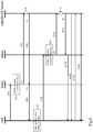
- FIG. 2 depicts an overview of the arrangement according to one aspect of the invention.
- MAG 1 may allocate a local prefix (e.g. P 1 ) for the MN and also communicate this prefix to the LMA (step 21 & 22).
- a local prefix is a prefix anchored at a MAG.
- a MN may configure one of its interfaces by using the prefix, e.g. prefix + an interface identifier. Through that interface, the MN may access Internet without routing through the LMA.
- the prefix may be stored in the Binding Cache of the LMA or other network entity, such as a DHCP (Dynamic Host Configuration Protocol) server.
- the Binding Cache and the DHCP server may be standalone network entity respectively or integrated into LMA due to performance reasons.
- the DHCP server may support both DHCPv4 and DHCPv6.
- Valid lifetime indicates the length of time an address or a prefix remains in the valid state (i.e., the time until invalidation). The valid lifetime must be greater than or equal to the preferred lifetime. When the valid lifetime expires, the address becomes invalid. Invalid addresses may not appear as the destination or source address of a packet. In case an invalid address is used as a destination address, the Internet routing system will be unable to deliver the packet. If it is used as a source address, the recipient of the packet will be unable to respond.
- Preferred lifetime is the length of time that a valid address or prefix is preferred (i.e., the time until deprecation). When the preferred lifetime expires, the address becomes deprecated.
- a deprecated address may no longer be used as a source address in new communications, but packets sent from or to deprecated addresses are delivered as expected.
- a deprecated address may continue to be used as a source address in communications where switching to a preferred address causes hardship to a specific upper-layer activity (e.g., an existing TCP connection).
- MAG 2 When the MN roams at step 24, it may initiate another attach request to MAG 2 which is located in Domain 2 (step 25).
- MAG 2 may allocate another local prefix (e.g. P 2 ) anchored at MAG 2 for the MN and also communicate the new local prefix to LMA.
- LMA may replace P 1 by P 2 in the Binding Cache entry.
- MAG 2 may provide the new prefix P 2 to MN and inform the MN to use the new local prefix P 2 and deprecate P 1 by setting preferred lifetime to be 0.
- the MN may configure one of its interfaces by using the new prefix so that it may access e.g. public Internet via MAG 2 without going through the LMA.
- a temporary tunnel may be established between MAG 1 and MAG 2 so that the reverse traffic (with respect to the data sent out when the previous P 1 was in use) heading for MAG 1 may still be routed to MAG 2 .
- such temporary tunnel may allow data traffic designating an IPv6 address comprising the old prefix reach the MN under the new MAG 2 as long as the valid lifetime of the old prefix is still valid.
- SLAAC Stateless Address Autoconfiguration Protocol
- DHCPv6 Dynamic Host Configuration Protocol v6
- the use of either protocol may depend on system level configuration.
- a LMA may comprise a DHCP server.
- the DHCP server may be a standalone entity.
- Figure 3 describes the signalling flow when Stateless Address Autoconfiguration Protocol (SLAAC) is used for local prefix management according to one embodiment of the invention.
- SLAAC Stateless Address Autoconfiguration Protocol
- a MN may initiate a request comprising its identifier to MAG 1 at step 31.
- MAG 1 e.g.
- the request may be sent via a layer 2 attach message.
- MAG 1 may allocate a first local prefix (e.g. P 1 ) for the MN at step 32 and set valid lifetime and preferred lifetime for the prefix according to its local configuration.
- MAG 1 may also generate a MN-ID in PMIPv6 domain for the MN.
- MN-ID is associated with the identifier of the MN obtained at radio access layer (at step 31).
- a short valid lifetime means frequent router advertisement update for a MN, which could increase the battery consumption in a wireless/cellular environment (due to the fact the MN may not be able to operate in power saving mode). If battery consumption of a MN is of utmost importance, valid lifetime may be increased to a higher value at the expenses of making the temporary local prefix invalidation time longer. Longer prefix invalidation time implies a longer period where P 1 may still be used under the MAG 2 , however, traffic using P 1 may be dropped as it topologically belongs to domain where MAG 1 is located.
- MAG 1 may inform LMA the MN-ID, the first local prefix (e.g. P 1 ) and the used valid lifetime at step 33.
- LMA may check if there is already an entry with respect to the MN-ID and if not, it may store these information either by itself in the binding cache or in another network entity, e.g. when binding cache is a standalone entity (step 34).
- a response comprising the stored information and HNP may be sent from LMA to MAG 1 (step 35).
- MAG 1 may detect that the received prefix is the first local prefix (P 1 ) which was sent to the LMA (step 36).
- MAG 1 may send a message comprising HNP, the first local prefix together with its attributes valid lifetime and preferred lifetime to the MN at step 37.
- a router advertisement (RA) message according to RFC4862 may be used for sending the message.
- the M-flag in the RA message may be set to 0 indicating MN that SLAAC is used for address configuration.
- the local prefix e.g. P 1
- PIO Prefix Information Option
- A-flag field in RA message may be set to 1 in order to indicate that the MN may use the prefix for stateless address autoconfiguration.
- the MN may roam at step 38.
- a handover may be performed at radio access layer so that the MN may be connected with MAG 2 after initiating another request comprising an identifier of the MN to MAG 2 at step 39.
- MAG 2 may be located in a different domain (e.g. Domain 2) than MAG 1 (e.g. Domain 1).
- MAG 2 may allocate a second local prefix (e.g. P 2 ) for the MN and set valid lifetime, used valid lifetime and preferred lifetime for the second local prefix (step 310), similar to step 32.
- MAG 2 may also generate a MN-ID in PMIPv6 domain for the MN.
- MN-ID is associated with the identifier of the MN obtained at radio access layer (at step 39). With respect to the same MN, the generated MN-ID should be identical.
- the second local prefix (e.g. P 2 ) and the used valid lifetime are delivered to LMA at step 311.
- LMA may check if there is already an entry for the MN-ID. If so, it may replace the previous local prefix (e.g. P 1 ) by the new prefix (e.g. P 2 ) and previous used valid lifetime by the new used valid lifetime at step 312.
- LMA may send a response to MAG 2 comprising HNP, P 1 and its (i.e. the previous) used valid lifetime at step 313.
- RA router advertisement
- the local prefix may be added to Prefix Information Option (PIO) field of the RA message.
- PIO Prefix Information Option
- M-flags field in RA may be set to 0 in order to inform the MN that SLAAC is used for address configuration.
- A-flag field in RA message's PIO option may be set to 1 in order to indicate that the MN may use the said prefixes for stateless address autoconfiguration.
- the MN may use the new prefix (e.g. P 2 ) to form an IPv6 address on one of its interface.
- the MN may access public Internet via MAG 2 bypassing LMA after a handover is performed from MAG 1 to MAG 2 .
- Figure 4 describes the signalling flow when DHCPv6 is used for local prefix management according to another embodiment of the invention. Whether SLAAC or DHCPv6 is used is determined by configuration of a system comprising MAG and LMA. When DHCPv6 is used for address configuration, M-flags in a RA message sent by a MAG may be set to 1 and the RA message need not contain any PIO.
- Step 41- 43 are identical to step 31-33 except that valid lifetime may be set by MAG 1 to any proper value depending on the network configuration.
- LMA may check if there is already an entry with respect to the MN-ID and if not, it may store these information either by itself in a binding cache or in another network entity, e.g. DHCP server (step 44).
- LMA or DHCP server may construct an IPv6 address using the received prefix and set valid lifetime and preferred lifetime for the IPv6 address based on the received valid lifetime and preferred lifetime.
- the LMA/DHCP server may set a different value to valid lifetime, but it may not bigger than the received used valid lifetime.
- LMA or DHCP server may send a DHCP message comprising the constructed IPv6 address together with valid lifetime, preferred lifetime and HNP to MAG 1 (step 45).
- the DHCP server/LMA may include the required Identity Association (IA) options into the DHCP messages, IA_TA (Identity Association for Temporary Address) options for local prefixes and IA_NA (Identity Association for Non-temporary Address) for the HNP.
- IA TA Identity Association for Temporary Address
- IA_NA Identity Association for Non-temporary Address
- the presence of IA TA and IA_NA fields is an indication to the MN to use the provided prefix for address configuration.
- MAG 1 determines that the message from LMA/DHCP comprises one IPv6 address constructed by using the first local prefix, it may relay the message to the MN (step 46).
- Step 47 - 410 are identical to step 38 -311 in Fig.3 except that valid lifetime may be set by MAG 2 to any proper value depending on the network configuration.
- LMA or DHCP server may check if there is already an entry for the MN-ID. If so, it may replace the previous local prefix (e.g. P 1 ) by the new prefix (e.g. P 2 ) and construct two IPv6 addresses by using P 1 and P 2 respectively. LMA may also set a proper valid lifetime and preferred lifetime for P 2 and deprecate P 1 by setting both valid lifetime and preferred lifetime to 0. In DHCP case, the communication between the LMA/DHCP server and the MN is assumed to be secure as there is existing deployed methods to secure DHCP signalling, thus valid lifetime may also be set to 0.
- LMA or DHCP server may send a message comprising the two P 1 and HNP to MAG 2 .
- MAG 2 When MAG 2 determines that the local prefix contained in the message from LMA/DHCP server is not the same as the second local prefix (e.g. P 2 ), it may send a RA message without the PIO field to MN at step 413.
- the M-flag field in the RA message may be set to 1 in order to indicate that DHCP is used for address configuration.
- LMA or DHCP server may send a reconfigure message to MN via MAG 2 as MAG 2 only relays the message (step 416).
- the message may comprise IA (Identity Association) in the ORO (Option Request Option) field so that a DHCP peer may tell the other peer what kind of options it is interested in and supports.
- the LMA/DHCP server may inform the MN to reconfigure its IA option.
- MN may send a renew message comprising IA_TA (Identity Association for Temporary Address) option field to LMA or DHCP server via MAG 2 (step 415) .
- IA_TA Identity Association for Temporary Address
- LMA or DHCP server may send a reply message to MN via MAG 2 , wherein the message comprising HNP, two IPv6 addresses formed by P 1 and P 2 respectively and their associated valid lifetime and preferred lifetime (step 416).
- the IPv6 addresses formed by P 1 and P 2 may be inserted to IA_TA ,and HNP may be inserted to IA NA option field in DHCP reply message.
- IA_TA and IA_NA options indicates that the MN may use the provided prefix for configuring its interface.
- the MN and the LMA/DHCP server may communicate to each other directly in steps 414-416.
- MAG 2 may be connected with the MN and may relay the messages between the MN and the LMA/DHCP server.
- Figure 5 describes a schematic block diagram of a MAG according to one aspect of the invention.
- a MAG (51) may comprise a first interface unit (52) configured to receive an attach request from a MN (e.g. step 31 in Fig.3 or step 41 in Fig.4 ).
- the MAG (51) may also comprise a processing unit (or a processing means) (54) configured to allocate a local prefix (e.g. P 1 or P 2 ) for a MN after receiving the attach request.
- Said processing unit may also generate a MN-ID in PMIPv6 domain for the MN.
- MN-ID is associated with the identifier of the MN obtained at radio access layer (at step 31 or 41).
- the MAG (51) may further comprise a second interface unit (53) configured to send a message comprising the allocated local prefix (e.g. P 1 or P 2 ) together with its associated used valid lifetime to a LMA or/and DHCP server.
- the second interface unit (53) may be configured to receive a response message from a LMA/DHCP server.
- SLAAC may be used for local prefix management.
- the response message received from a LMA may comprise a HNP, a local prefix (e.g. P 1 or P 2 ) associated with the MN-ID and its used valid lifetime (e.g. step 33 or 311 in Fig.3 ).
- the processing unit may be configured to send a message comprising the allocated local prefix and its associated valid lifetime and preferred lifetime to the MN (e.g. step 37 in Fig.3 )
- the processing unit may be configured to send a message comprising both prefixes, i.e. the received one (e.g. P 1 ) and the allocated one (e.g. P 2 ), to the MN.
- the received one e.g. P 1
- the local prefix may be added to Prefix Information Option (PIO) field of the RA message.
- PIO Prefix Information Option
- A-flag filed in RA message should be set to 1 in order to indicate that the MN may use the prefix for stateless address autoconfiguration.
- the M-flag in a RA may be set to 0.
- DHCP may be used for local prefix management.
- the response message received from a LMA/DHCP server may comprise a HNP, one IPv6 address comprising a local prefix associated with the MN-ID and its attributes (e.g. valid lifetime and preferred lifetime ) (e.g. step 45 in Fig.4 ). If the processing unit determines that the local prefix is identical to the one previously sent to LMA/DHCP server (e.g. in step 43 in Fig.4 ) , the processing unit may be configured to relay the message to the MN.
- the processing unit may be configured to send a RA message without PIO field to the MN (e.g. step 413).
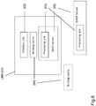
- Figure 6 describes a schematic block diagram illustrating a LMA according to another aspect of the invention.
- a LMA (61) may comprise a binding cache (64) configured to store information received from a network entity such as a MAG.
- the binding cache (64) may be a standalone entity.
- the LMA may comprise an interface unit (62) configured to receive a message (e.g. step 33 & 311 in Fig.3 or step 43 & 410 in Fig.4 ) comprising a MN-ID, a local prefix (e.g. P 1 or P 2 ) allocated for the MN of the MN-ID and its associated attribute used valid lifetime from a MAG.
- the LMA may further comprise a processing unit (or a processing means) (63) configured to check if there is already an entry regarding the MN-ID in the binding cache upon receiving the message.
- said processing unit (63) may be configured to set up the entry for the MN-ID, otherwise, said processing unit may be configured to replace the exiting prefix (e.g. P 1 ) by the newly received prefix (e.g. P 2 ) in the binding cache if the received local prefix is not the same as the one stored in the binding cache (64).
- said processing unit may be configured to replace the exiting prefix (e.g. P 1 ) by the newly received prefix (e.g. P 2 ) in the binding cache if the received local prefix is not the same as the one stored in the binding cache (64).
- SLAAC may be used for local prefix management. If no entry regarding a received MN-ID is found in the binding cache, the processing unit may be configured to send a message comprising the received the MN-ID, the prefix (e.g. P 1 or P 2 ) and the attribute used valid lifetime to the MAG (e.g. step 35 in Fig.3 ). If there is already an entry in the binding cache and the received local prefix (e.g. P 2 ), with respect to the MN-ID, is not the same as the one stored (e.g. P 1 ) in the binding cache, said processing unit may be configured to send a message comprising the previous local prefix (e.g. P 1 ) and its associated used valid lifetime to the MAG (e.g. step 313 in Fig.3 ).
- the processing unit may be configured to send a message comprising the previous local prefix (e.g. P 1 ) and its associated used valid lifetime to the MAG (e.g. step 313 in Fig.3 ).
- DHCPv6 may be used for local prefix management. If no entry regarding a received MN-ID is found in the binding cache, the processing unit (63) may be configured to set the valid lifetime and preferred lifetime for the received prefix based on the received used valid lifetime. The valid lifetime may be set to a different value than used valid lifetime but it may not bigger than used valid lifetime. The preferred lifetime may be bigger than 0 but smaller than valid lifetime. The processing unit may be configured to send a message comprising the received HNP, an IPv6 address comprising the received prefix (e.g. P 1 ) and the valid lifetime and preferred lifetime to the MAG (e.g. step 45 in Fig.4 ).
- said processing unit may be configured to set the attributes valid lifetime and preferred lifetime for the received prefix (e.g. P 2 ) based on the received used valid lifetime and to deprecate the previous prefix (e.g. P 1 ) by setting both its valid lifetime and preferred lifetime to 0.
- Said processing unit may be configured to send a message comprising two IPv6 addresses formed with the previous (e.g. P 1 ) and received local prefix (e.g. P 2 ) respectively and their associated attributes (e.g.
- the IPv6 address may be inserted to IA TA optional field of IA field of DHCP reply message.
- IA_TA option implies that the MN may use the prefix for configuring its interface.
- Said processing unit may be configured to send a reconfigure message to the MN directly (e.g. step 414 in Fig.4 ) and said interface unit may be configured to receive a renew message from the MN directly (e.g. step 415 in Fig.4 ).
- Said processing unit may be located in the DHCP server as well according to different embodiment of the invention.
Description
- The invention addresses issues regarding how to improve routing in a network, in particular, where IPv6 (Internet Protocol v6) is adopted as IP protocol and, on the top of which, Proxy Mobile IPv6 (PMIPv6) is deployed as mobility management protocol.
- In a network where Internet operates under IPv6, IPv6 address shall be assigned to each constituent network element. IPv6 addresses are logically divided into two parts: a 64-bit (sub-)network prefix and a 64-bit interface identifier. A network prefix is normally associated with a specific domain, which means that a data packet designated to an IPv6 address comprising the network prefix may be routed to a router/network entity located in that specific domain.
- On top of IPv6, PMIPv6 may be deployed as a network layer protocol for managing mobility of mobile nodes (MN) as depicted in
Fig.1 . In PMIPv6 domain, there are two important network entities - Local Mobility Anchor (LMA) and the Mobile Access Gateway (MAG). MAG is a function on an access router that manages the mobility related signaling for a MN attached to its access link, e.g. a radio link. LMA is the home agent for a MN in PMIPv6 domain. A mobile node identifier (MN-ID) may be assigned to a MN in PMIPv6 domain. It is a stable identifier of a MN that mobility entities in PMIPv6 domain can always acquire and use for predictably identifying a MN. This is typically an identifier such as a network access identifier (NAI) or other identifier such as a media access control (MAC) address. - When a MN initially tries to attach to a network, a Home Network Prefix (HNP) is generated in LMA and assigned to the link between the MN and a MAG, e.g., MAG1 as shown in
Fig.1 . The home network prefix is anchored at LMA (which means that a data packet designated to an IPv6 address comprising the prefix as its network prefix would be routed to LMA) and indicates the home network of the MN. More than one prefix can be assigned to the link between MN and MAG according to PMIPv6. The MN may configure its interfaces with one or more addresses from the obtained home network prefix, e.g. home network prefix + an interface identifier. When the MN roams, a handover in access link layer may be performed and as the result, the MN may be connected with a new MAG, e.g., MAG2, located in a different domain than MAG1. However, due to the originally assigned HNP, all the IP traffic is delivered to and from the MN via LMA and MAG2. Moreover, the home network associated with the home network prefix may be in completely different domain (e.g. Domain 3) than MAG2 which is located inDomain 2. When traffic volumes grow significantly and the majority of the IP services are provided locally in IP topology wise, the LMA could easily become a bottleneck as it may become the traffic concentrator for multiple MAGs. - "Approaches to Distributed mobility management using Mobile IPv6 and its extensions draft-patil-mext-dmm-approaches-00.txt", IETF, STANDARD WORKING DRAFT, 7 March 2011 relates to a mobility model in which mobility functions are distributed is a way of alleviating the concerns of a gateway centric approach in which mobile hosts are anchored at a gateway via a tunnel.
- "A Summary of Distributed Mobility Management draft-kuntz-dmm-summary-00.txt", IETF, STANDARD WORKING DRAFT, 6 May 2011 relates to Distributed Mobility Management (DMM) and operational considerations on setting up Mobile IPv6 networks so that traffic is distributed in an optimal way.
- "Dynamic Mobility Anchoring draft-seite-netext-dma-OO.txt", IETF, STANDARD WORKING DRAFT, 19 May 2010 relates to a mobility anchor maintaining Mobile Nodes (MNs) binding up-to-date and deployment of a Proxy Mobile IP approach in a mobility architecture "flattened" by confining mobility support in the access network.
- "Use of Proxy Mobile IPv6 for Distributed Mobility Control; draft-sjkoh-mext-pmip-dmc-01 .txt"; IETF; STANDARD WORKING DRAFT, 14 March 2011 relates to using the Proxy Mobile IPv6 (PMIP) protocol for distributed mobility control and two schemes of distributed mobility control: Signal-driven PMIP (S-PMIP) and Signal-driven Distributed PMIP (SD-PMIP).
- The present invention and its embodiments seek to address one or more of the above-described drawbacks and shortcomings. According to a first aspect of the invention, there is provided a method at a mobile access gateway according to
claim 1. - According to another aspect of the invention, there is provided method for a server according to claim 4.
- According to a third aspect of the invention, there is provided a network element according to claim 9.
- According to a fourth aspect of the invention, there is provided a server according to claim 12.
- According to a fifth aspect of the invention, there is provided a computer program product according to claim 17.
- According to a sixth aspect of the invention, there is provided a computer program product according to claim 18.
- Exemplary embodiments of the invention are described below, by way of example only, with reference to the following numbered drawings.
-
Figure 1 is an exemplary example illustrating a network where PMIPv6 is deployed as mobility management protocol for mobile nodes (MN). -
Figure 2 briefly describes the overall arrangement of the solution according to one aspect of the invention. -
Figure 3 depicts message flow among MN, MAGs and LMA when Stateless Address Autoconfiguration Protocol (SLAAC) is used for local prefix management according to one embodiment of the invention. -
Figure 4 describes the signalling flow when DHCPv6 (Dynamic Host Configuration Protocol v6) is used for local prefix management according to another embodiment of the invention. -
Figure 5 shows a schematic block diagram illustrating a MAG according to one aspect of the invention. -
Figure 6 shows a schematic block diagram illustrating a LMA according to another aspect of the invention. - In order to avoid the above-mentioned bottleneck effect, especially when the amount of traffic grows significantly, it is desired to allow a MN to directly access public Internet via a local MAG (e.g. MAG1 or MAG2) to which it is connected, bypassing the LMA.
Figure 2 depicts an overview of the arrangement according to one aspect of the invention. - Assuming a MN tries to connect to a MAG e.g. MAG1. It may initiate an attach request to MAG1. MAG1 may allocate a local prefix (e.g. P1) for the MN and also communicate this prefix to the LMA (step 21 & 22). A local prefix is a prefix anchored at a MAG. A MN may configure one of its interfaces by using the prefix, e.g. prefix + an interface identifier. Through that interface, the MN may access Internet without routing through the LMA. The prefix may be stored in the Binding Cache of the LMA or other network entity, such as a DHCP (Dynamic Host Configuration Protocol) server. The Binding Cache and the DHCP server may be standalone network entity respectively or integrated into LMA due to performance reasons. The DHCP server may support both DHCPv4 and DHCPv6.
- There are two attributes, valid lifetime and preferred lifetime, associated with a local prefix. Valid lifetime indicates the length of time an address or a prefix remains in the valid state (i.e., the time until invalidation). The valid lifetime must be greater than or equal to the preferred lifetime. When the valid lifetime expires, the address becomes invalid. Invalid addresses may not appear as the destination or source address of a packet. In case an invalid address is used as a destination address, the Internet routing system will be unable to deliver the packet. If it is used as a source address, the recipient of the packet will be unable to respond.
Preferred lifetime is the length of time that a valid address or prefix is preferred (i.e., the time until deprecation). When the preferred lifetime expires, the address becomes deprecated. Assigning a deprecated address to an interface is not recommended, but not forbidden. A deprecated address may no longer be used as a source address in new communications, but packets sent from or to deprecated addresses are delivered as expected. A deprecated address may continue to be used as a source address in communications where switching to a preferred address causes hardship to a specific upper-layer activity (e.g., an existing TCP connection). - When the MN roams at
step 24, it may initiate another attach request to MAG2 which is located in Domain 2 (step 25). MAG2 may allocate another local prefix (e.g. P2) anchored at MAG2 for the MN and also communicate the new local prefix to LMA. LMA may replace P1 by P2 in the Binding Cache entry. MAG2 may provide the new prefix P2 to MN and inform the MN to use the new local prefix P2 and deprecate P1 by setting preferred lifetime to be 0. The MN may configure one of its interfaces by using the new prefix so that it may access e.g. public Internet via MAG2 without going through the LMA. - In an application, there may be a certain period when both P1 and P2 are usable, e.g. their valid lifetime have not yet expired. A temporary tunnel may be established between MAG1 and MAG2 so that the reverse traffic (with respect to the data sent out when the previous P1 was in use) heading for MAG1 may still be routed to MAG2. In other words, such temporary tunnel may allow data traffic designating an IPv6 address comprising the old prefix reach the MN under the new MAG2 as long as the valid lifetime of the old prefix is still valid. Once the valid lifetime of the old prefix P1 expires, the tunnel between MAG1 and MAG2 and routing entries may be removed.
- According to different embodiments of the invention, Stateless Address Autoconfiguration Protocol (SLAAC) and DHCPv6 (Dynamic Host Configuration Protocol v6) may be adopted for prefix management. The use of either protocol may depend on system level configuration. In the case of DHCPv6, a LMA may comprise a DHCP server. Alternatively, the DHCP server may be a standalone entity.
Figure 3 describes the signalling flow when Stateless Address Autoconfiguration Protocol (SLAAC) is used for local prefix management according to one embodiment of the invention. A MN may initiate a request comprising its identifier to MAG1 atstep 31. Depending on the technology being used at radio access layer, e.g. Wireless LAN (WLAN), 3G and etc, the identifier may be different. For instance, it may be an identifier of the MN or an interface identifier of the MN. In the case of 3G or LTE, the identifier may be IMSI (= International Mobile Subscriber Identity). The request may be sent via alayer 2 attach message. Upon receiving the request, MAG1 may allocate a first local prefix (e.g. P1) for the MN atstep 32 and set valid lifetime and preferred lifetime for the prefix according to its local configuration. MAG1 may set used valid lifetime the same value as valid lifetime (i.e. used valid lifetime = valid lifetime). MAG1 may also generate a MN-ID in PMIPv6 domain for the MN. MN-ID is associated with the identifier of the MN obtained at radio access layer (at step 31). - In some embodiments, it is may be recommended to set valid lifetime between e.g. 30-60 seconds to allow rapid invalidation of the prefix. A short valid lifetime means frequent router advertisement update for a MN, which could increase the battery consumption in a wireless/cellular environment (due to the fact the MN may not be able to operate in power saving mode). If battery consumption of a MN is of utmost importance, valid lifetime may be increased to a higher value at the expenses of making the temporary local prefix invalidation time longer. Longer prefix invalidation time implies a longer period where P1 may still be used under the MAG2, however, traffic using P1 may be dropped as it topologically belongs to domain where MAG1 is located.
- Then MAG1 may inform LMA the MN-ID, the first local prefix (e.g. P1) and the used valid lifetime at
step 33. LMA may check if there is already an entry with respect to the MN-ID and if not, it may store these information either by itself in the binding cache or in another network entity, e.g. when binding cache is a standalone entity (step 34). Then a response comprising the stored information and HNP may be sent from LMA to MAG1 (step 35). Upon receiving the response from LMA, MAG1 may detect that the received prefix is the first local prefix (P1) which was sent to the LMA (step 36). MAG1 may send a message comprising HNP, the first local prefix together with its attributes valid lifetime and preferred lifetime to the MN atstep 37. A router advertisement (RA) message according to RFC4862 may be used for sending the message. The M-flag in the RA message may be set to 0 indicating MN that SLAAC is used for address configuration. The local prefix (e.g. P1) may be inserted to Prefix Information Option (PIO) field of the RA message. A-flag field in RA message may be set to 1 in order to indicate that the MN may use the prefix for stateless address autoconfiguration. - According to one aspect of the invention, the MN may roam at
step 38. A handover may be performed at radio access layer so that the MN may be connected with MAG2 after initiating another request comprising an identifier of the MN to MAG2 atstep 39. MAG2 may be located in a different domain (e.g. Domain 2) than MAG1 (e.g. Domain 1). Upon receiving the request, MAG2 may allocate a second local prefix (e.g. P2) for the MN and set valid lifetime, used valid lifetime and preferred lifetime for the second local prefix (step 310), similar to step 32. MAG2 may also generate a MN-ID in PMIPv6 domain for the MN. MN-ID is associated with the identifier of the MN obtained at radio access layer (at step 39). With respect to the same MN, the generated MN-ID should be identical. - Similar to step 33, MN-ID, the second local prefix (e.g. P2) and the used valid lifetime are delivered to LMA at
step 311. Based on the obtained MN-ID, LMA may check if there is already an entry for the MN-ID. If so, it may replace the previous local prefix (e.g. P1) by the new prefix (e.g. P2) and previous used valid lifetime by the new used valid lifetime atstep 312. LMA may send a response to MAG2 comprising HNP, P1 and its (i.e. the previous) used valid lifetime atstep 313. - Upon receiving the response from LMA, MAG2 may detect that the received local prefix (e.g. P1) is not the second local prefix (e.g. P2) which has been sent to LMA (step 314). MAG2 may deprecate P1 by re-setting its valid lifetime and preferred lifetime, e.g. valid lifetime = used valid lifetime; preferred lifetime = 0. If the MN can trust the received RA, valid lifetime may be set to 0 as well. At step 315, MAG2 may send a message comprising HNP, both P1 and P2 together with their associated valid lifetime and preferred lifetime to the MN. Similar to step 37, a router advertisement (RA) message according to RFC4862 may be used for sending the message. The local prefix may be added to Prefix Information Option (PIO) field of the RA message. M-flags field in RA may be set to 0 in order to inform the MN that SLAAC is used for address configuration. A-flag field in RA message's PIO option may be set to 1 in order to indicate that the MN may use the said prefixes for stateless address autoconfiguration.
- After receiving the two prefixes, the MN may use the new prefix (e.g. P2) to form an IPv6 address on one of its interface. Thus, the MN may access public Internet via MAG2 bypassing LMA after a handover is performed from MAG1 to MAG2.
-
Figure 4 describes the signalling flow when DHCPv6 is used for local prefix management according to another embodiment of the invention. Whether SLAAC or DHCPv6 is used is determined by configuration of a system comprising MAG and LMA. When DHCPv6 is used for address configuration, M-flags in a RA message sent by a MAG may be set to 1 and the RA message need not contain any PIO. - Step 41- 43 are identical to step 31-33 except that valid lifetime may be set by MAG1 to any proper value depending on the network configuration.
- Upon receiving a message comprising the first local prefix (e.g. P1) anchored at MAG1, LMA may check if there is already an entry with respect to the MN-ID and if not, it may store these information either by itself in a binding cache or in another network entity, e.g. DHCP server (step 44). LMA or DHCP server may construct an IPv6 address using the received prefix and set valid lifetime and preferred lifetime for the IPv6 address based on the received valid lifetime and preferred lifetime. The LMA/DHCP server may set a different value to valid lifetime, but it may not bigger than the received used valid lifetime. Then LMA or DHCP server may send a DHCP message comprising the constructed IPv6 address together with valid lifetime, preferred lifetime and HNP to MAG1 (step 45). The DHCP server/LMA may include the required Identity Association (IA) options into the DHCP messages, IA_TA (Identity Association for Temporary Address) options for local prefixes and IA_NA (Identity Association for Non-temporary Address) for the HNP. The presence of IA TA and IA_NA fields is an indication to the MN to use the provided prefix for address configuration. When MAG1 determines that the message from LMA/DHCP comprises one IPv6 address constructed by using the first local prefix, it may relay the message to the MN (step 46).
- Step 47 - 410 are identical to step 38 -311 in
Fig.3 except that valid lifetime may be set by MAG2 to any proper value depending on the network configuration. - In
step 411, LMA or DHCP server may check if there is already an entry for the MN-ID. If so, it may replace the previous local prefix (e.g. P1) by the new prefix (e.g. P2) and construct two IPv6 addresses by using P1 and P2 respectively. LMA may also set a proper valid lifetime and preferred lifetime for P2 and deprecate P1 by setting both valid lifetime and preferred lifetime to 0. In DHCP case, the communication between the LMA/DHCP server and the MN is assumed to be secure as there is existing deployed methods to secure DHCP signalling, thus valid lifetime may also be set to 0. - At
step 412, LMA or DHCP server may send a message comprising the two P1 and HNP to MAG2. - When MAG2 determines that the local prefix contained in the message from LMA/DHCP server is not the same as the second local prefix (e.g. P2), it may send a RA message without the PIO field to MN at
step 413. The M-flag field in the RA message may be set to 1 in order to indicate that DHCP is used for address configuration. - LMA or DHCP server may send a reconfigure message to MN via MAG2 as MAG2 only relays the message (step 416). The message may comprise IA (Identity Association) in the ORO (Option Request Option) field so that a DHCP peer may tell the other peer what kind of options it is interested in and supports. By sending this message, the LMA/DHCP server may inform the MN to reconfigure its IA option.
In reply to the reconfigure message, MN may send a renew message comprising IA_TA (Identity Association for Temporary Address) option field to LMA or DHCP server via MAG2 (step 415) . - LMA or DHCP server may send a reply message to MN via MAG2, wherein the message comprising HNP, two IPv6 addresses formed by P1 and P2 respectively and their associated valid lifetime and preferred lifetime (step 416). The IPv6 addresses formed by P1 and P2 may be inserted to IA_TA ,and HNP may be inserted to IA NA option field in DHCP reply message. The use of IA_TA and IA_NA options indicates that the MN may use the provided prefix for configuring its interface.
- In IP layer, the MN and the LMA/DHCP server may communicate to each other directly in steps 414-416. In radio link layer, MAG2 may be connected with the MN and may relay the messages between the MN and the LMA/DHCP server.
-
Figure 5 describes a schematic block diagram of a MAG according to one aspect of the invention. - A MAG (51) may comprise a first interface unit (52) configured to receive an attach request from a MN (
e.g. step 31 inFig.3 or step 41 inFig.4 ). The MAG (51) may also comprise a processing unit (or a processing means) (54) configured to allocate a local prefix (e.g. P1 or P2) for a MN after receiving the attach request. Said processing unit may set valid lifetime and preferred lifetime for the prefix and set used valid lifetime the same value as valid lifetime (i.e. used valid lifetime = valid lifetime). Said processing unit may also generate a MN-ID in PMIPv6 domain for the MN. MN-ID is associated with the identifier of the MN obtained at radio access layer (atstep 31 or 41). The MAG (51) may further comprise a second interface unit (53) configured to send a message comprising the allocated local prefix (e.g. P1 or P2) together with its associated used valid lifetime to a LMA or/and DHCP server. The second interface unit (53) may be configured to receive a response message from a LMA/DHCP server. - According to one embodiment of the invention, SLAAC may be used for local prefix management. In this case, the response message received from a LMA may comprise a HNP, a local prefix (e.g. P1 or P2) associated with the MN-ID and its used valid lifetime (e.g.
step Fig.3 ). - If the received local prefix is identical to the prefix sent to the LMA previously (
e.g. step 33 inFig.3 ), the processing unit may be configured to send a message comprising the allocated local prefix and its associated valid lifetime and preferred lifetime to the MN (e.g. step 37 inFig.3 ) - If the received local prefix is different from the prefix sent to the LMA previously (
e.g. step 311 inFig.3 ), the processing unit may be configured to send a message comprising both prefixes, i.e. the received one (e.g. P1) and the allocated one (e.g. P2), to the MN. The received one (e.g. P1) may be deprecated by setting its preferred lifetime to 0 and setting its valid lifetime to the received used valid lifetime (i.e. valid lifetime = used valid lifetime). The local prefix may be added to Prefix Information Option (PIO) field of the RA message. A-flag filed in RA message should be set to 1 in order to indicate that the MN may use the prefix for stateless address autoconfiguration. The M-flag in a RA may be set to 0. - According to another embodiment of the invention, DHCP may be used for local prefix management. The response message received from a LMA/DHCP server may comprise a HNP, one IPv6 address comprising a local prefix associated with the MN-ID and its attributes (e.g. valid lifetime and preferred lifetime) (
e.g. step 45 inFig.4 ). If the processing unit determines that the local prefix is identical to the one previously sent to LMA/DHCP server (e.g. instep 43 inFig.4 ) , the processing unit may be configured to relay the message to the MN. - If the processing unit determines that the local prefix is not the same as the one previously sent to LMA/DHCP server (e.g. in
step 410 inFig.4 ), the processing unit may be configured to send a RA message without PIO field to the MN (e.g. step 413). -
Figure 6 describes a schematic block diagram illustrating a LMA according to another aspect of the invention. - A LMA (61) may comprise a binding cache (64) configured to store information received from a network entity such as a MAG. Alternatively, the binding cache (64) may be a standalone entity. The LMA may comprise an interface unit (62) configured to receive a message (e.g.
step 33 & 311 inFig.3 or step 43 & 410 inFig.4 ) comprising a MN-ID, a local prefix (e.g. P1 or P2) allocated for the MN of the MN-ID and its associated attribute used valid lifetime from a MAG. The LMA may further comprise a processing unit (or a processing means) (63) configured to check if there is already an entry regarding the MN-ID in the binding cache upon receiving the message. If not, said processing unit (63) may be configured to set up the entry for the MN-ID, otherwise, said processing unit may be configured to replace the exiting prefix (e.g. P1) by the newly received prefix (e.g. P2) in the binding cache if the received local prefix is not the same as the one stored in the binding cache (64). - According to one embodiment of the invention, SLAAC may be used for local prefix management. If no entry regarding a received MN-ID is found in the binding cache, the processing unit may be configured to send a message comprising the received the MN-ID, the prefix (e.g. P1 or P2) and the attribute used valid lifetime to the MAG (e.g.
step 35 inFig.3 ). If there is already an entry in the binding cache and the received local prefix (e.g. P2), with respect to the MN-ID, is not the same as the one stored (e.g. P1) in the binding cache, said processing unit may be configured to send a message comprising the previous local prefix (e.g. P1) and its associated used valid lifetime to the MAG (e.g. step 313 inFig.3 ). - According to another embodiment of the invention, DHCPv6 may be used for local prefix management. If no entry regarding a received MN-ID is found in the binding cache, the processing unit (63) may be configured to set the valid lifetime and preferred lifetime for the received prefix based on the received used valid lifetime. The valid lifetime may be set to a different value than used valid lifetime but it may not bigger than used valid lifetime. The preferred lifetime may be bigger than 0 but smaller than valid lifetime. The processing unit may be configured to send a message comprising the received HNP, an IPv6 address comprising the received prefix (e.g. P1) and the valid lifetime and preferred lifetime to the MAG (e.g.
step 45 inFig.4 ). - If there is already an entry in the binding cache and the received local prefix (e.g. P2), with respect to the MN-ID, is not the same as the one stored (e.g. P1) in the binding cache, said processing unit may be configured to set the attributes valid lifetime and preferred lifetime for the received prefix (e.g. P2) based on the received used valid lifetime and to deprecate the previous prefix (e.g. P1) by setting both its valid lifetime and preferred lifetime to 0. Said processing unit may be configured to send a message comprising two IPv6 addresses formed with the previous (e.g. P1) and received local prefix (e.g. P2) respectively and their associated attributes (e.g. valid lifetime and preferred lifetime) to the MAG (
e.g. step 416 inFig.4 ). The IPv6 address may be inserted to IA TA optional field of IA field of DHCP reply message. The use of IA_TA option implies that the MN may use the prefix for configuring its interface. - Said processing unit may be configured to send a reconfigure message to the MN directly (
e.g. step 414 inFig.4 ) and said interface unit may be configured to receive a renew message from the MN directly (e.g. step 415 inFig.4 ). - Said processing unit may be located in the DHCP server as well according to different embodiment of the invention.
- For the purpose of the present invention as described above, it should be noted that
- method steps likely to be implemented as software code portions and being run using a processor at one of the server entities are software code independent and can be specified using any known or future developed programming language;
- method steps and/or devices likely to be implemented as hardware components at one of the server entities are hardware independent and can be implemented using any known or future developed hardware technology or any hybrids of these, such as MOS, CMOS, BiCMOS, ECL, TTL, etc, using for example ASIC components or DSP components, as an example;
- generally, any method step is suitable to be implemented as software or by hardware without changing the idea of the present invention;
- devices can be implemented as individual devices, but this does not exclude that they are implemented in a distributed fashion throughout the system, as long as the functionality of the device is preserved.
- It is to be understood that the above description is illustrative of the invention and is not to be construed as limiting the invention. Various modifications and applications may occur to those skilled in the art without departing from the scope of the invention as defined by the appended claims.
Claims (18)
- A method at a proxy mobile IPv6 mobile access gateway comprising
receiving a request (31; 41) from a node (MN);
obtaining, based on the received request, an identifier relevant to said node;
allocating a first local prefix (P1) anchored at the proxy mobile IPv6 mobile access gateway (51);
setting a first timer indicating a length of time the first local prefix or an address comprising the first local prefix is valid;
setting a second timer indicating a length of time the first local prefix or the address comprising the first local prefix is preferred when the first local prefix or the address is valid and after which the first local prefix or the address is deprecated such that it can no longer be used as a source address in new communications; and
sending a first message (33; 43) comprising said identifier, said first local prefix and said first timer to a network element (61). - The method according to claim 1, further comprising receiving a response message (313; 412) comprising a second local prefix (P2) and a third timer indicating a length of time the second local prefix or an address comprising the second local prefix is valid;
determining (314) if said second local prefix (P2) is identical to the first local prefix (P1) ;
in the event that said second local prefix (P2) is identical to the first local prefix (P1),
sending to the node (MN) a second message comprising the first local prefix (P1), the first timer, the second timer and an indication to use the prefix for address configuration;
in the event that the second local prefix (P2) is different from the first local prefix (P1),
setting a fourth timer indicating a length of time the second local prefix (P2) or the address comprising the second local prefix (P2) is preferred when the second local prefix (P2) or the address is valid to 0,
sending a second message (315) comprising the first local prefix (P1), the first timer, the second timer, the second local prefix (P2), the third timer, the fourth timer, and an indication to use a prefix for address configuration to the node (MN). - The method according to claim 1, further comprising receiving, from said network element (61), a response message (313) comprising a second local prefix (P2), a third timer indicating a length of time the second local prefix (P2) or an address comprising the second local prefix (P2) is valid, and an indication to use a prefix for address configuration; determining (314) if said second local prefix (P2) is identical to the first local prefix (P1) ;
in the event that said second local prefix (P2) is identical to the first local prefix (P1),
sending the received response message to the node (MN);
in the event that the second local prefix (P2) is different from the first local prefix (P1),
sending a router advertisement message to the node. - A method comprising
receiving, from a network entity (51), a message (33;43) comprising an identifier relevant to a node, a first local prefix (P1) anchored at the network entity (51) and a first timer indicating a length of time the first local prefix (P1) or an address comprising the first local prefix (P1) is valid;
determining if an entry associated with the identifier exists or not;
in the event that the entry does not exist,
storing (34;44) the received information,
sending a response (35) to the network entity (51) to enable the network entity to provide the first local prefix (P1), the first timer, a second timer indicating a length of time the first local prefix or the address comprising the first local prefix is preferred when the first local prefix or the address is valid and after which the first local prefix or the address is deprecated such that it can no longer be used as a source address in new communications, and an indication to use the prefix for address configuration to a node. - The method according to claim 4, further comprising,
in the event that the entry exists, wherein said entry comprises a second local prefix (P2) anchored at the network entity (51) and a third timer indicating a length of time the second local prefix or an address comprising the second local prefix is valid,
replacing the second local prefix (P2) and the third timer by the first local prefix (P1) and the first timer. - The method according to claim 5, wherein said method being implemented by using a stateless address autoconfiguration protocol, said method further comprising sending a message (311) comprising the second local prefix (P2) and the third timer.
- The method according claim 5, wherein said method being implemented by using a dynamic host configuration protocol v6, said method further comprising
sending a message (410) comprising the second local prefix (P2) . - The method according claim 7, further comprising setting a second timer indicating a length of time the first local prefix (P1) or the address comprising the first local prefix (P1) is preferred when the first local prefix or the address is valid,
setting a fourth timer indicating a length of time the second local prefix or the address comprising the second local prefix is preferred when the second local prefix or the address is valid to 0,
setting the third timer to 0,
sending a response message comprising the first timer, the second timer, the third timer, the fourth timer, the first and the second local prefix, and an indication to use a prefix for address configuration to the node. - A network element (51) comprising a processing unit (54), a first interface unit (52) and a second interface unit (53), wherein,
said first interface unit is configured to receive a request (31; 41) from a node (MN);
said processing unit is configured to
obtain, based on the received request, an identifier relevant to said node (MN),
allocate a first local prefix (P1) anchored at the network element (51),
set a first timer indicating a length of time the first local prefix or an address comprising the first local prefix is valid;
set a second timer indicating a length of time the first local prefix or the address comprising the first local prefix is preferred when the first local prefix or the address is valid and after which the first local prefix or the address is deprecated such that it can no longer be used as a source address in new communications, and
send a first message (33; 43) comprising said identifier, said first local prefix and said first timer to a network element (61) through the second interface unit. - The network element (51) according to claim 9, wherein said second interface unit (53) is configured to receive a response message (313; 412) comprising a second local prefix (P2) and a third timer indicating a length of time the second local prefix (P2) or an address comprising the second local prefix (P2) is valid;
said processing unit (54) is further configured to determine if said second local prefix (P2) is identical to the first local prefix (P1) ;
in the event that said second local prefix is identical to the first local prefix (P1),
said processing unit (54) is configured to send to the node (MN) a second message comprising the first local prefix, the first timer, the second timer and an indication to use the prefix for address configuration through said first interface unit (52);
in the event that the second local prefix is different from the first local prefix (P1),
said processing unit is configured to
set a fourth timer indicating a length of time the second local prefix (P2) or the address comprising the second local prefix (P2) is preferred when the second local prefix or the address is valid to 0, and
send a second message (315) comprising the first local prefix (P1), the first timer, the second timer, the second local prefix (P2), the third timer, the fourth timer, and an indication to use a prefix for address configuration to the node (MN) through said first interface unit (52). - The network element (51) according to claim 9, wherein
said second interface unit (53) is configured to receive, from said network element (61), a response message (313) comprising a second local prefix (P2), a third timer indicating a length of time the second local prefix (P2) or an address comprising the second local prefix (P2) is valid, and an indication to use a prefix for address configuration; said processing unit is further configured to determine (314) if said second local prefix (P2) is identical to the first local prefix (P1) ;
in the event that said second local prefix (P2) is identical to the first local prefix (P1),
said processing unit is configured to send the received response message to the node (MN) through said first interface unit;
in the event that the second local prefix (P2) is different from the first local prefix (P1),
said processing unit is configured to send a router advertisement message to the node (MN) through said first interface unit (52). - A server (61) comprising a processing unit (63), an interface unit (62) and a database, wherein,
said interface unit (62) is configured to receive, from a network entity (51), a message (33;43) comprising an identifier relevant to a node, a first local prefix (P1) anchored at the network entity (51) and a first timer indicating a length of time the first local prefix (P1) or an address comprising the first local prefix (P1) is valid;
said processing unit (63) is configured to determine if an entry associated with the identifier exists or not;
in the event that the entry does not exist,
said database is configured to store the received information,
said processing unit is configured to
send a response (35) to the network entity (51) to enable the network entity (51) to provide the first local prefix (P1), the first timer, a second timer indicating a length of time the first local prefix (P1) or the address comprising the first local prefix (P1) is preferred when the first local prefix (P1) or the address is valid and after which the first local prefix or the address is deprecated such that it can no longer be used as a source address in new communications, to the network entity (51) through said interface unit (62). - The server (61) according to claim 12, wherein
in the event that the entry exists and said entry comprises a second local prefix (P2) anchored at the network entity (51) and a third timer indicating a length of time the second local prefix or an address comprising the second local prefix is valid,
said processing unit is configured to replace the second local prefix (P2) and the third timer by the first local prefix (P2) and the first timer. - The server (61) according to claim 13, wherein said server being configured to implement a stateless address autoconfiguration protocol, said processing unit (63) is further configured to
send a message (311) comprising the second local prefix (P2) and the third timer to the network entity through said interface unit (62). - The server according to claim 13, wherein said server being configured to implement a dynamic host configuration protocol, said processing unit is further configured to send a message (410) comprising the second local prefix (P2) through said interface unit (62).
- The server (61) according to claim 15, wherein said processing unit (63) is further configured to set a second timer indicating a length of time the first local prefix (P1) or the address comprising the first local prefix (P1) is preferred when the first local prefix or the address is valid,
set a fourth timer indicating a length of time the second local prefix or the address comprising the second local prefix is preferred when the second local prefix or the address is valid to 0,
set the third timer to 0, and
send a response message comprising the first timer, the second timer, the third timer, the fourth timer, the first and the second local prefix, and an indication to use a prefix for address configuration to the node through said interface unit (62). - A computer program product comprising:a software code portion when run using a processor for receiving a request (31; 41) from a node (MN);a software code portion when run using a processor for obtaining, based on the received request, an identifier relevant to said node;a software code portion when run using a processor for allocating a first local prefix (P1) anchored at a proxy mobile IPv6 mobile access gateway;a software code portion when run using a processor for setting a first timer indicating a length of time the first local prefix (P1) or an address comprising the first local prefix (P1) is valid;a software code portion when run using a processor for setting a second timer indicating a length of time the first local prefix (P1) or the address comprising the first local prefix (P1) is preferred when the first local prefix(P1) orthe address is valid and after which the first local prefix or the address is deprecated such that it can no longer be used as a source address in new communications; anda software code portion for sending a first message (33; 43) comprising said identifier, said first local prefix and said first timer to a network element (61).
- A computer program product comprising:a software code portion when run using a processor for receiving, from a network entity (51), a message (33;43) comprising an identifier relevant to a node, a first local prefix (P1) anchored at the network entity (51) and a first timer indicating a length of time the first local prefix (P1) or an address comprising the first local prefix (P1) is valid;a software code portion when run using a processor for determining if an entry associated with the identifier exists or not;in the event that the entry does not exist,a software code portion when run using a processor for storing (34;44) the received information,a software code portion when run using a processor for sending a response (35) to the network entity (51) to enable the network entity to provide the first local prefix (P1),the first timer, a second timer indicating a length of time the first local prefix or the address comprising the first local prefix is preferred when the first local prefix or the address is valid and after which the first local prefix or the address is deprecated such that it can no longer be used as a source address in new communications, and an indication to use the prefix for address configuration to a node.
Applications Claiming Priority (1)
| Application Number | Priority Date | Filing Date | Title |
|---|---|---|---|
| PCT/EP2011/057735 WO2012155944A1 (en) | 2011-05-13 | 2011-05-13 | Apparatus and method for routing in a network |
Publications (2)
| Publication Number | Publication Date |
|---|---|
| EP2708012A1 EP2708012A1 (en) | 2014-03-19 |
| EP2708012B1 true EP2708012B1 (en) | 2018-07-04 |
Family
ID=46026783
Family Applications (1)
| Application Number | Title | Priority Date | Filing Date |
|---|---|---|---|
| EP11719268.2A Not-in-force EP2708012B1 (en) | 2011-05-13 | 2011-05-13 | Methods for prefix allocation and corresponding network element, server and computer program products |
Country Status (3)
| Country | Link |
|---|---|
| US (1) | US9986425B2 (en) |
| EP (1) | EP2708012B1 (en) |
| WO (2) | WO2012155944A1 (en) |
Families Citing this family (13)
| Publication number | Priority date | Publication date | Assignee | Title |
|---|---|---|---|---|
| CN102843441B (en) * | 2011-06-24 | 2017-02-22 | 华为技术有限公司 | Method and device for controlling address configuration way |
| US20140321328A1 (en) * | 2011-11-29 | 2014-10-30 | Interdigital Patent Holdings, Inc. | Methods For IP Mobility Management |
| FR2987540B1 (en) * | 2012-02-28 | 2016-05-13 | Commissariat Energie Atomique | METHOD AND SYSTEM FOR MANAGING THE MOBILITY OF A MOBILE NETWORK |
| JP6078876B2 (en) * | 2013-02-13 | 2017-02-15 | パナソニックIpマネジメント株式会社 | Wireless communication system, wireless device, and address setting method thereof |
| US9271197B2 (en) * | 2013-05-22 | 2016-02-23 | Futurewei Technologies, Inc. | System and method for distributed evolved packet core architecture |
| US10986551B2 (en) * | 2013-10-11 | 2021-04-20 | Universiti Putra Malaysia | Method for managing a low latency handover for mobile host seamless mobility |
| CN105325031B (en) | 2014-05-30 | 2020-01-21 | 华为技术有限公司 | Service path changing method and device |
| US10512001B2 (en) | 2015-08-17 | 2019-12-17 | Lg Electronics Inc. | Method for rearranging gateway and method for generating dedicated bearer |
| FR3041846A1 (en) * | 2015-09-29 | 2017-03-31 | Orange | TECHNIQUE FOR MANAGING AN ADDRESS IN A LOCAL NETWORK |
| CN105554178B (en) * | 2015-12-31 | 2019-07-19 | 上海华为技术有限公司 | A kind of method, gateway and the system of address distribution |
| CN106411743B (en) * | 2016-11-14 | 2019-08-20 | 锐捷网络股份有限公司 | A kind of method and apparatus of Message processing |
| CN108848100B (en) * | 2018-06-27 | 2020-10-20 | 清华大学 | Stateful IPv6 address generation method and device |
| US11929850B2 (en) * | 2021-03-31 | 2024-03-12 | Fortinet, Inc. | Dynamic elimination of old IPv6 addresses from WLAN/BYOD/IOT devices INDHCPv6 stateless mode after transitioning between VLANs |
Family Cites Families (15)
| Publication number | Priority date | Publication date | Assignee | Title |
|---|---|---|---|---|
| KR100579834B1 (en) * | 2003-10-20 | 2006-05-15 | 삼성전자주식회사 | Method for assigning address based on IP site-local prefix pool in Mobile Ad-hoc Network |
| US7542458B2 (en) * | 2003-11-25 | 2009-06-02 | Qualcomm Incorporated | Method and apparatus for efficiently using air-link resources to maintain IP connectivity for intermittently active wireless terminals |
| KR100637076B1 (en) * | 2005-01-12 | 2006-10-23 | 삼성전기주식회사 | Optimized binary search with anti-collision mathod and system |
| JPWO2008105176A1 (en) * | 2007-02-27 | 2010-06-03 | パナソニック株式会社 | Communication method, communication system, mobile node, proxy node, and management node |
| US8483174B2 (en) * | 2007-04-20 | 2013-07-09 | Qualcomm Incorporated | Method and apparatus for providing gateway relocation |
| US8488557B2 (en) * | 2008-01-14 | 2013-07-16 | Alcatel Lucent | Method for detecting a duplicate address, mobile station, network element and communication system |
| WO2009101780A1 (en) * | 2008-02-12 | 2009-08-20 | Panasonic Corporation | Position information management device, network edge device, and mobile terminal |
| US8788826B1 (en) * | 2008-06-06 | 2014-07-22 | Marvell International Ltd. | Method and apparatus for dynamically allocating a mobile network prefix to a mobile terminal |
| CN101448252B (en) * | 2008-06-20 | 2011-03-16 | 中兴通讯股份有限公司 | Network switching implementation method, system thereof and mobile nodes |
| US20110116475A1 (en) * | 2008-07-23 | 2011-05-19 | Panasonic Corporation | Vertical handoff method, vertical handoff system, home agent, and mobile node |
| EP2320604B1 (en) * | 2008-08-26 | 2016-09-28 | Alcatel Lucent | Method and device for transferring packet in ipv6 access node |
| US8676999B2 (en) * | 2008-10-10 | 2014-03-18 | Futurewei Technologies, Inc. | System and method for remote authentication dial in user service (RADIUS) prefix authorization application |
| EP2457409A1 (en) | 2009-07-24 | 2012-05-30 | Nokia Siemens Networks OY | Method and device for conveying traffic in a proxy mobile ip system |
| US8457025B2 (en) * | 2009-08-28 | 2013-06-04 | Telefonaktiebolaget L M Ericsson (Publ) | Method and network node for selecting a network prefix to be advertised in a communication network |
| US8832238B2 (en) * | 2011-09-12 | 2014-09-09 | Microsoft Corporation | Recording stateless IP addresses |
-
2011
- 2011-05-13 EP EP11719268.2A patent/EP2708012B1/en not_active Not-in-force
- 2011-05-13 WO PCT/EP2011/057735 patent/WO2012155944A1/en active Application Filing
- 2011-05-13 US US14/116,805 patent/US9986425B2/en active Active
-
2012
- 2012-04-19 WO PCT/EP2012/057123 patent/WO2012156171A1/en active Application Filing
Non-Patent Citations (1)
| Title |
|---|
| None * |
Also Published As
| Publication number | Publication date |
|---|---|
| US20140098812A1 (en) | 2014-04-10 |
| WO2012155944A1 (en) | 2012-11-22 |
| WO2012156171A1 (en) | 2012-11-22 |
| US9986425B2 (en) | 2018-05-29 |
| EP2708012A1 (en) | 2014-03-19 |
Similar Documents
| Publication | Publication Date | Title |
|---|---|---|
| EP2708012B1 (en) | Methods for prefix allocation and corresponding network element, server and computer program products | |
| EP1260113B1 (en) | Hierarchical mobility management for wireless networks | |
| US7746873B2 (en) | Communication processing system, communication processing method, communication terminal, data transfer controller, and program | |
| JP4491980B2 (en) | COMMUNICATION PROCESSING SYSTEM, COMMUNICATION PROCESSING METHOD, COMMUNICATION TERMINAL DEVICE, AND PROGRAM | |
| US7788405B2 (en) | Method for automatic configuration of prefixes at maps in HMIPv6 | |
| US9307477B1 (en) | Apparatus and method for interfacing wireless client device to multiple packet data networks | |
| US20100268804A1 (en) | Address allocation method, address allocation system, mobile node, and proxy node | |
| JP4902634B2 (en) | Method of providing mobility management protocol information for handover in a mobile communication system to a mobile terminal | |
| EP1833204A1 (en) | Fast configuration of a default router for a mobile node in a mobile communication system | |
| WO2009116246A1 (en) | Communication method, communication system, mobile node, access router | |
| KR102477066B1 (en) | Terminal device, AMF, SMF, core network device, and communication control method | |
| JP2010521847A (en) | Interface selection in mobile networks | |
| CN101111067A (en) | Mobile terminal and communication method for gateway access | |
| WO2006104202A1 (en) | Communication control method, address management node, and mobile node | |
| CN101448237B (en) | Discovery method of home link in mobile IP | |
| EP2536071B1 (en) | Method, system, mapping forward server and access router for mobile communication controlling | |
| WO2013102445A1 (en) | System and method for distributed mobility management | |
| WO2003069872A1 (en) | Discovery of an agent or a server in an ip network | |
| US20090119412A1 (en) | Support for avoidance of unnecessary tunneling | |
| EP1841143A1 (en) | Efficent handover of a mobile node within a network with multiple anchor points | |
| US20150009977A1 (en) | Method and system for managing the mobility of a mobile network | |
| GB2400269A (en) | Method of handoff in a packet-switched data communication network | |
| KR101037531B1 (en) | Method for providing soft handover using communication state information in wireless internet system | |
| WO2003107600A1 (en) | A method and system for local mobility management | |
| WO2017152690A1 (en) | Method for active reconfiguration of network prefix in proxy mobile ipv6 |
Legal Events
| Date | Code | Title | Description |
|---|---|---|---|
| PUAI | Public reference made under article 153(3) epc to a published international application that has entered the european phase |
Free format text: ORIGINAL CODE: 0009012 |
|
| 17P | Request for examination filed |
Effective date: 20131213 |
|
| AK | Designated contracting states |
Kind code of ref document: A1 Designated state(s): AL AT BE BG CH CY CZ DE DK EE ES FI FR GB GR HR HU IE IS IT LI LT LU LV MC MK MT NL NO PL PT RO RS SE SI SK SM TR |
|
| DAX | Request for extension of the european patent (deleted) | ||
| STAA | Information on the status of an ep patent application or granted ep patent |
Free format text: STATUS: EXAMINATION IS IN PROGRESS |
|
| 17Q | First examination report despatched |
Effective date: 20161214 |
|
| GRAP | Despatch of communication of intention to grant a patent |
Free format text: ORIGINAL CODE: EPIDOSNIGR1 |
|
| STAA | Information on the status of an ep patent application or granted ep patent |
Free format text: STATUS: GRANT OF PATENT IS INTENDED |
|
| RIC1 | Information provided on ipc code assigned before grant |
Ipc: H04W 80/04 20090101ALN20171221BHEP Ipc: H04L 29/12 20060101AFI20171221BHEP Ipc: H04W 8/26 20090101ALI20171221BHEP Ipc: H04L 12/741 20130101ALI20171221BHEP |
|
| INTG | Intention to grant announced |
Effective date: 20180109 |
|
| GRAS | Grant fee paid |
Free format text: ORIGINAL CODE: EPIDOSNIGR3 |
|
| GRAA | (expected) grant |
Free format text: ORIGINAL CODE: 0009210 |
|
| STAA | Information on the status of an ep patent application or granted ep patent |
Free format text: STATUS: THE PATENT HAS BEEN GRANTED |
|
| AK | Designated contracting states |
Kind code of ref document: B1 Designated state(s): AL AT BE BG CH CY CZ DE DK EE ES FI FR GB GR HR HU IE IS IT LI LT LU LV MC MK MT NL NO PL PT RO RS SE SI SK SM TR |
|
| REG | Reference to a national code |
Ref country code: GB Ref legal event code: FG4D |
|
| REG | Reference to a national code |
Ref country code: CH Ref legal event code: EP |
|
| REG | Reference to a national code |
Ref country code: AT Ref legal event code: REF Ref document number: 1015723 Country of ref document: AT Kind code of ref document: T Effective date: 20180715 |
|
| REG | Reference to a national code |
Ref country code: IE Ref legal event code: FG4D |
|
| REG | Reference to a national code |
Ref country code: DE Ref legal event code: R096 Ref document number: 602011049739 Country of ref document: DE |
|
| REG | Reference to a national code |
Ref country code: NL Ref legal event code: MP Effective date: 20180704 |
|
| REG | Reference to a national code |
Ref country code: LT Ref legal event code: MG4D |
|
| REG | Reference to a national code |
Ref country code: AT Ref legal event code: MK05 Ref document number: 1015723 Country of ref document: AT Kind code of ref document: T Effective date: 20180704 |
|
| PG25 | Lapsed in a contracting state [announced via postgrant information from national office to epo] |
Ref country code: NL Free format text: LAPSE BECAUSE OF FAILURE TO SUBMIT A TRANSLATION OF THE DESCRIPTION OR TO PAY THE FEE WITHIN THE PRESCRIBED TIME-LIMIT Effective date: 20180704 |
|
| PG25 | Lapsed in a contracting state [announced via postgrant information from national office to epo] |
Ref country code: CZ Free format text: LAPSE BECAUSE OF FAILURE TO SUBMIT A TRANSLATION OF THE DESCRIPTION OR TO PAY THE FEE WITHIN THE PRESCRIBED TIME-LIMIT Effective date: 20180704 Ref country code: BG Free format text: LAPSE BECAUSE OF FAILURE TO SUBMIT A TRANSLATION OF THE DESCRIPTION OR TO PAY THE FEE WITHIN THE PRESCRIBED TIME-LIMIT Effective date: 20181004 Ref country code: AT Free format text: LAPSE BECAUSE OF FAILURE TO SUBMIT A TRANSLATION OF THE DESCRIPTION OR TO PAY THE FEE WITHIN THE PRESCRIBED TIME-LIMIT Effective date: 20180704 Ref country code: GR Free format text: LAPSE BECAUSE OF FAILURE TO SUBMIT A TRANSLATION OF THE DESCRIPTION OR TO PAY THE FEE WITHIN THE PRESCRIBED TIME-LIMIT Effective date: 20181005 Ref country code: IS Free format text: LAPSE BECAUSE OF FAILURE TO SUBMIT A TRANSLATION OF THE DESCRIPTION OR TO PAY THE FEE WITHIN THE PRESCRIBED TIME-LIMIT Effective date: 20181104 Ref country code: RS Free format text: LAPSE BECAUSE OF FAILURE TO SUBMIT A TRANSLATION OF THE DESCRIPTION OR TO PAY THE FEE WITHIN THE PRESCRIBED TIME-LIMIT Effective date: 20180704 Ref country code: LT Free format text: LAPSE BECAUSE OF FAILURE TO SUBMIT A TRANSLATION OF THE DESCRIPTION OR TO PAY THE FEE WITHIN THE PRESCRIBED TIME-LIMIT Effective date: 20180704 Ref country code: NO Free format text: LAPSE BECAUSE OF FAILURE TO SUBMIT A TRANSLATION OF THE DESCRIPTION OR TO PAY THE FEE WITHIN THE PRESCRIBED TIME-LIMIT Effective date: 20181004 Ref country code: PL Free format text: LAPSE BECAUSE OF FAILURE TO SUBMIT A TRANSLATION OF THE DESCRIPTION OR TO PAY THE FEE WITHIN THE PRESCRIBED TIME-LIMIT Effective date: 20180704 Ref country code: FI Free format text: LAPSE BECAUSE OF FAILURE TO SUBMIT A TRANSLATION OF THE DESCRIPTION OR TO PAY THE FEE WITHIN THE PRESCRIBED TIME-LIMIT Effective date: 20180704 Ref country code: SE Free format text: LAPSE BECAUSE OF FAILURE TO SUBMIT A TRANSLATION OF THE DESCRIPTION OR TO PAY THE FEE WITHIN THE PRESCRIBED TIME-LIMIT Effective date: 20180704 |
|
| PG25 | Lapsed in a contracting state [announced via postgrant information from national office to epo] |
Ref country code: LV Free format text: LAPSE BECAUSE OF FAILURE TO SUBMIT A TRANSLATION OF THE DESCRIPTION OR TO PAY THE FEE WITHIN THE PRESCRIBED TIME-LIMIT Effective date: 20180704 Ref country code: ES Free format text: LAPSE BECAUSE OF FAILURE TO SUBMIT A TRANSLATION OF THE DESCRIPTION OR TO PAY THE FEE WITHIN THE PRESCRIBED TIME-LIMIT Effective date: 20180704 Ref country code: AL Free format text: LAPSE BECAUSE OF FAILURE TO SUBMIT A TRANSLATION OF THE DESCRIPTION OR TO PAY THE FEE WITHIN THE PRESCRIBED TIME-LIMIT Effective date: 20180704 Ref country code: HR Free format text: LAPSE BECAUSE OF FAILURE TO SUBMIT A TRANSLATION OF THE DESCRIPTION OR TO PAY THE FEE WITHIN THE PRESCRIBED TIME-LIMIT Effective date: 20180704 |
|
| REG | Reference to a national code |
Ref country code: DE Ref legal event code: R097 Ref document number: 602011049739 Country of ref document: DE |
|
| PG25 | Lapsed in a contracting state [announced via postgrant information from national office to epo] |
Ref country code: IT Free format text: LAPSE BECAUSE OF FAILURE TO SUBMIT A TRANSLATION OF THE DESCRIPTION OR TO PAY THE FEE WITHIN THE PRESCRIBED TIME-LIMIT Effective date: 20180704 Ref country code: EE Free format text: LAPSE BECAUSE OF FAILURE TO SUBMIT A TRANSLATION OF THE DESCRIPTION OR TO PAY THE FEE WITHIN THE PRESCRIBED TIME-LIMIT Effective date: 20180704 Ref country code: RO Free format text: LAPSE BECAUSE OF FAILURE TO SUBMIT A TRANSLATION OF THE DESCRIPTION OR TO PAY THE FEE WITHIN THE PRESCRIBED TIME-LIMIT Effective date: 20180704 |
|
| PLBE | No opposition filed within time limit |
Free format text: ORIGINAL CODE: 0009261 |
|
| STAA | Information on the status of an ep patent application or granted ep patent |
Free format text: STATUS: NO OPPOSITION FILED WITHIN TIME LIMIT |
|
| PG25 | Lapsed in a contracting state [announced via postgrant information from national office to epo] |
Ref country code: SM Free format text: LAPSE BECAUSE OF FAILURE TO SUBMIT A TRANSLATION OF THE DESCRIPTION OR TO PAY THE FEE WITHIN THE PRESCRIBED TIME-LIMIT Effective date: 20180704 Ref country code: DK Free format text: LAPSE BECAUSE OF FAILURE TO SUBMIT A TRANSLATION OF THE DESCRIPTION OR TO PAY THE FEE WITHIN THE PRESCRIBED TIME-LIMIT Effective date: 20180704 Ref country code: SK Free format text: LAPSE BECAUSE OF FAILURE TO SUBMIT A TRANSLATION OF THE DESCRIPTION OR TO PAY THE FEE WITHIN THE PRESCRIBED TIME-LIMIT Effective date: 20180704 |
|
| 26N | No opposition filed |
Effective date: 20190405 |
|
| PGFP | Annual fee paid to national office [announced via postgrant information from national office to epo] |
Ref country code: DE Payment date: 20190430 Year of fee payment: 9 |
|
| PG25 | Lapsed in a contracting state [announced via postgrant information from national office to epo] |
Ref country code: SI Free format text: LAPSE BECAUSE OF FAILURE TO SUBMIT A TRANSLATION OF THE DESCRIPTION OR TO PAY THE FEE WITHIN THE PRESCRIBED TIME-LIMIT Effective date: 20180704 |
|
| PGFP | Annual fee paid to national office [announced via postgrant information from national office to epo] |
Ref country code: GB Payment date: 20190508 Year of fee payment: 9 |
|
| REG | Reference to a national code |
Ref country code: CH Ref legal event code: PL |
|
| PG25 | Lapsed in a contracting state [announced via postgrant information from national office to epo] |
Ref country code: LI Free format text: LAPSE BECAUSE OF NON-PAYMENT OF DUE FEES Effective date: 20190531 Ref country code: MC Free format text: LAPSE BECAUSE OF FAILURE TO SUBMIT A TRANSLATION OF THE DESCRIPTION OR TO PAY THE FEE WITHIN THE PRESCRIBED TIME-LIMIT Effective date: 20180704 Ref country code: CH Free format text: LAPSE BECAUSE OF NON-PAYMENT OF DUE FEES Effective date: 20190531 |
|
| REG | Reference to a national code |
Ref country code: BE Ref legal event code: MM Effective date: 20190531 |
|
| PG25 | Lapsed in a contracting state [announced via postgrant information from national office to epo] |
Ref country code: LU Free format text: LAPSE BECAUSE OF NON-PAYMENT OF DUE FEES Effective date: 20190513 |
|
| PG25 | Lapsed in a contracting state [announced via postgrant information from national office to epo] |
Ref country code: TR Free format text: LAPSE BECAUSE OF FAILURE TO SUBMIT A TRANSLATION OF THE DESCRIPTION OR TO PAY THE FEE WITHIN THE PRESCRIBED TIME-LIMIT Effective date: 20180704 |
|
| PG25 | Lapsed in a contracting state [announced via postgrant information from national office to epo] |
Ref country code: IE Free format text: LAPSE BECAUSE OF NON-PAYMENT OF DUE FEES Effective date: 20190513 |
|
| PG25 | Lapsed in a contracting state [announced via postgrant information from national office to epo] |
Ref country code: BE Free format text: LAPSE BECAUSE OF NON-PAYMENT OF DUE FEES Effective date: 20190531 |
|
| PG25 | Lapsed in a contracting state [announced via postgrant information from national office to epo] |
Ref country code: PT Free format text: LAPSE BECAUSE OF FAILURE TO SUBMIT A TRANSLATION OF THE DESCRIPTION OR TO PAY THE FEE WITHIN THE PRESCRIBED TIME-LIMIT Effective date: 20181105 Ref country code: FR Free format text: LAPSE BECAUSE OF NON-PAYMENT OF DUE FEES Effective date: 20190531 |
|
| REG | Reference to a national code |
Ref country code: DE Ref legal event code: R119 Ref document number: 602011049739 Country of ref document: DE |
|
| GBPC | Gb: european patent ceased through non-payment of renewal fee |
Effective date: 20200513 |
|
| PG25 | Lapsed in a contracting state [announced via postgrant information from national office to epo] |
Ref country code: GB Free format text: LAPSE BECAUSE OF NON-PAYMENT OF DUE FEES Effective date: 20200513 |
|
| PG25 | Lapsed in a contracting state [announced via postgrant information from national office to epo] |
Ref country code: CY Free format text: LAPSE BECAUSE OF FAILURE TO SUBMIT A TRANSLATION OF THE DESCRIPTION OR TO PAY THE FEE WITHIN THE PRESCRIBED TIME-LIMIT Effective date: 20180704 Ref country code: DE Free format text: LAPSE BECAUSE OF NON-PAYMENT OF DUE FEES Effective date: 20201201 |
|
| PG25 | Lapsed in a contracting state [announced via postgrant information from national office to epo] |
Ref country code: MT Free format text: LAPSE BECAUSE OF FAILURE TO SUBMIT A TRANSLATION OF THE DESCRIPTION OR TO PAY THE FEE WITHIN THE PRESCRIBED TIME-LIMIT Effective date: 20180704 Ref country code: HU Free format text: LAPSE BECAUSE OF FAILURE TO SUBMIT A TRANSLATION OF THE DESCRIPTION OR TO PAY THE FEE WITHIN THE PRESCRIBED TIME-LIMIT; INVALID AB INITIO Effective date: 20110513 |
|
| PG25 | Lapsed in a contracting state [announced via postgrant information from national office to epo] |
Ref country code: MK Free format text: LAPSE BECAUSE OF FAILURE TO SUBMIT A TRANSLATION OF THE DESCRIPTION OR TO PAY THE FEE WITHIN THE PRESCRIBED TIME-LIMIT Effective date: 20180704 |