EP2707709B1 - Method and apparatus for analyzing alkalinity conditions in aqueous liquids - Google Patents
Method and apparatus for analyzing alkalinity conditions in aqueous liquids Download PDFInfo
- Publication number
- EP2707709B1 EP2707709B1 EP12720506.0A EP12720506A EP2707709B1 EP 2707709 B1 EP2707709 B1 EP 2707709B1 EP 12720506 A EP12720506 A EP 12720506A EP 2707709 B1 EP2707709 B1 EP 2707709B1
- Authority
- EP
- European Patent Office
- Prior art keywords
- container
- alkalinity
- liquid
- pressure
- sample
- Prior art date
- Legal status (The legal status is an assumption and is not a legal conclusion. Google has not performed a legal analysis and makes no representation as to the accuracy of the status listed.)
- Active
Links
Images
Classifications
-
- G—PHYSICS
- G01—MEASURING; TESTING
- G01N—INVESTIGATING OR ANALYSING MATERIALS BY DETERMINING THEIR CHEMICAL OR PHYSICAL PROPERTIES
- G01N31/00—Investigating or analysing non-biological materials by the use of the chemical methods specified in the subgroup; Apparatus specially adapted for such methods
- G01N31/16—Investigating or analysing non-biological materials by the use of the chemical methods specified in the subgroup; Apparatus specially adapted for such methods using titration
-
- G—PHYSICS
- G01—MEASURING; TESTING
- G01N—INVESTIGATING OR ANALYSING MATERIALS BY DETERMINING THEIR CHEMICAL OR PHYSICAL PROPERTIES
- G01N31/00—Investigating or analysing non-biological materials by the use of the chemical methods specified in the subgroup; Apparatus specially adapted for such methods
-
- G—PHYSICS
- G01—MEASURING; TESTING
- G01N—INVESTIGATING OR ANALYSING MATERIALS BY DETERMINING THEIR CHEMICAL OR PHYSICAL PROPERTIES
- G01N33/00—Investigating or analysing materials by specific methods not covered by groups G01N1/00 - G01N31/00
- G01N33/18—Water
-
- C—CHEMISTRY; METALLURGY
- C02—TREATMENT OF WATER, WASTE WATER, SEWAGE, OR SLUDGE
- C02F—TREATMENT OF WATER, WASTE WATER, SEWAGE, OR SLUDGE
- C02F2209/00—Controlling or monitoring parameters in water treatment
- C02F2209/07—Alkalinity
Definitions
- the present invention concerns a method and apparatus for determining total alkalinity in aqueous solutions and more specifically its relative contribution by the components OH - , CO 3 2- , and HCO 3 2- .
- a method for controlling chemistry of a glycol containing liquid in a system for recovery of glycol is also comprised.
- a specific and commercially important application is in relation to recovery of petroleum products, especially offshore, where mixtures of petroleum components, inevitably comprise some water, and in which circulation/ recirculation of a glycol containing liquid is used for hydrate inhibition in the production system for gas and condensate.
- glycol we mean here the various forms of glycol compositions, mono-ethylene glycol (MEG) [ethane-1,2-diol], di-ethylene glycol (DEG) [2-hydroxyethoxy)ethan-2-ol], Tri-ethylene glycol (TEG) [2-[2-(2-Hydroxyethoxy)ethoxy]ethanol], and other Poly-ethylene glycols (PEG) as well as propylene glycol (PG) [1,2-propanediol].
- MEG mono-ethylene glycol
- DEG di-ethylene glycol
- TEG Tri-ethylene glycol
- PEG Poly-ethylene glycols
- PEG Poly-ethylene glycols
- PG propylene glycol
- Zhu Jianmin et al. (The Institution of Electrical Engineers, Stevenage, GB “Development of total alkalinity grey control system of boiler water", Journal of Grey System Sci-Tech, Information Services UK, vol 18, No 2, November 12 2009, p 93-102 ISSN; 0957-3720 ) describes a method for indirect determination of boiler water total alkalinity through measuring online pH, temperature and boiler pressure.
- US patent No. 4 277 343 A teaches a method for continuously monitoring and controlling the total alkalinity attributable to carbon dioxide, bicarbonate ion and carbonate ion such as found in water and waste water treatment systems and in cooling towers.
- the method includes the steps of sampling the aqueous solution. Adjusting the pH of the sample, detecting with a pCO2 probe the total carbon dioxide of the sample and adding an alkalinity-controlling chemical to the aqueous solution.
- a method for continuously monitoring the total alkalinity in a natural body of water is also describes.
- Japanese publication JP 2009-264913 A teaches a method for providing an underwater total alkalinity determination using acidimetry.
- the commonly used principle for determining the condition of such solutions comprises isolating an amount of the solution to be controlled and titrate with acid and alternative method is to allow CO 2 to bubble through the solution until is it saturated therewith, whereafter pH is measured.
- a disadvantage with the first method is that it fails when the solution contains bases that are weaker than bicarbonate.
- a disadvantage with the second method is that the amount of CO 2 added is not known and the pH value measured therefore does not reveal all information of interest. In addition, bubbles generate foam in the solution, making measurements difficult. Any presence of salts of (weak) organic acids, which commonly occur, will interfere with the measurements based on titration.
- the present invention is a.
- the invention comprises an apparatus for performing the method, said apparatus being disclosed by claim 9.
- the present invention concerns a method related to controlling chemistry of glycol-containing-liquid in a system for recovery of glycol as defined by claim 13, said method comprising all steps in the method according to the first aspect of the invention.
- Preferred embodiments of the inventions are disclosed by the dependent claims.
- unbonded CO 2 as used herein is understood dissolved or dispersed CO 2 molecules in the liquid, i.e. not in the form of HCO 3 - or CO 3 2- .
- the method according to the present invention may be carried out as a fully manual operation, the method may also be automatized and set to run at fixed or programmable intervals.
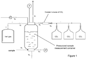
- Figure 1 is a schematic drawing of an apparatus for automatic performance of the method according to the present invention.
- Figure 1 illustrates schematically an embodiment of an automated analyzer of the present invention, and a possible rough automation sequence process will be described hereinafter with reference to figure 2.
- the fluid being measured is typically under pressure, and separated from the analyzer by the valve V2.
- the fluid to be sampled is allowed in at V2, and fills up the measurement container up to 90 % of the total volume of the container.
- the container is typically filled with a gas not containing CO 2 , such as nitrogen, which may have been blown through the measurement container at the end of the preceding measurement. Venting the pre-existing gas (nitrogen) may be done at V1 upon opening V2, or it may be done afterwards.
- a gas not containing CO 2 such as nitrogen
- Venting the pre-existing gas (nitrogen) may be done at V1 upon opening V2, or it may be done afterwards.
- a foaming sample it may be an advantage not to vent at the beginning, let the sample in, let the foam be pressurized and settle for a time, then open V1 to obtain wished pressure.
- An alternative in the case of foam may be to connect V1 to a tube projecting further inside the measurement container so as first to let liquid out when opening V1.
- An alternative is also to fill up the measurement container thanks to vacuum, generated by a vacuum pump and transmitted by V8. Filling may be controlled by pressure, by a timer and/or by for example, filling level control sensors (represented here by a Level Switch High, LSH, and a Level Switch Low, LSL).
- one of the CO 2 removal operations can be performed: bubbling with a non-CO 2 containing gas, heating, resting, or applying vacuum.
- pressure and pH are measured.
- a fixed and known quantity of CO 2 gas is let in, for example by opening V5 after a calibrated buffer volume has been filled by CO 2 under pressure, preferably higher than the sample pressure.
- the calibrated volume is then refilled for next measurement thanks to the sequential control of valves V4 and V5.
- An alternative is to let CO2 in based on a timer controlling opening of an inlet valve. After CO 2 has been let in, a stirrer is run for typically several minutes.
- a new set of measures of pressure P and pH is taken, and alkalinity characteristics derived. Then, the container is emptied and cleaned. For example, V2 is opened and under the pressure of gas, the container expels the liquid when opening V6, and an extra flushing or drying can be performed by flowing a liquid or a gas, for example an inert gas, through V7, blowing away the remaining drops of liquid out at V6. Finally, V6 is shut, then V7.
- a liquid or a gas for example an inert gas
- All sensors, valve actuators and controls are driven by a control system, based on a personal computer, a Programmable Logic Controller (PLC), or any other control system as known in the art.
- PLC Programmable Logic Controller
- C CO 2 , d + C OH ⁇ + C CO 3 2 ⁇ mo 0 ⁇ mo 1 / V V
- C CO2,d is the molar concentration of CO 2 dissolved in liquid
- C OH - is the molar concentration of OH - reacting with CO 2
- C CO3 2- is the molar concentration of CO 3 2- reacting with CO 2
- mo 0 is mole CO 2 added
- mo 1 is mole CO 2 in the gas at equilibrium
- Vv is the sampled amount (volume) of liquid.
- sampled liquid does not contain CO 2 , which is not chemically bonded
- the apparatus should preferably be equipped with suitable means therefore.
- inert gas any gas not interfering with the measurements, typically N 2 , while principally any gas not containing CO 2 could be used as inert gas.
- the amount of liquid sampled should not exceed 90 % of the container volume and neither constitute less than 10 % of the container volume.
- the pressure should be maintained at a level no higher than 55 bar while a pressure in the range between 3 and 10 bar is preferred. Reducing the pressure under 3 bar may result in less precise measurements while increasing the pressure above 10 bar will require inconveniently expensive equipment.
- the apparatus should preferably be approved for a pressure of at least 3 bar and more preferably at least 10 bar to allow versatility of use.
- the apparatus should preferably comprise means for adding defined quantities of alkalinity or acid with known concentration.
- an analyzer according to the present invention would fit in a portable box. This enables a more flexible use by operators, and reduces volume required and costs.
- the present invention as discussed above thus fulfills the above mentioned objects and provides a method and an apparatus offering a highly improved control of the alkalinity conditions in aqueous liquids irrespective of application.
Landscapes
- Life Sciences & Earth Sciences (AREA)
- Health & Medical Sciences (AREA)
- Chemical & Material Sciences (AREA)
- General Physics & Mathematics (AREA)
- Physics & Mathematics (AREA)
- Analytical Chemistry (AREA)
- Biochemistry (AREA)
- General Health & Medical Sciences (AREA)
- Immunology (AREA)
- Pathology (AREA)
- Molecular Biology (AREA)
- Engineering & Computer Science (AREA)
- Food Science & Technology (AREA)
- Medicinal Chemistry (AREA)
- Investigating Or Analyzing Non-Biological Materials By The Use Of Chemical Means (AREA)
- Preventing Corrosion Or Incrustation Of Metals (AREA)
Description
- The present invention concerns a method and apparatus for determining total alkalinity in aqueous solutions and more specifically its relative contribution by the components OH-, CO3 2-, and HCO3 2-. A method for controlling chemistry of a glycol containing liquid in a system for recovery of glycol is also comprised.
- In some connection it is important to control the alkalinity of aqueous solutions. This may be the case in chemical industrial processes where it is important to maintain alkalinity within certain limits to ensure desired reactivity or the opposite, e.g. to prevent corrosion or the like.
- A specific and commercially important application is in relation to recovery of petroleum products, especially offshore, where mixtures of petroleum components, inevitably comprise some water, and in which circulation/ recirculation of a glycol containing liquid is used for hydrate inhibition in the production system for gas and condensate. In such connections, it is important to have control over alkalinity. This includes control of alkalinity in water-lean glycol injected into the production system and in the salt removal systems used for regeneration of water-rich glycol.
- By glycol, we mean here the various forms of glycol compositions, mono-ethylene glycol (MEG) [ethane-1,2-diol], di-ethylene glycol (DEG) [2-hydroxyethoxy)ethan-2-ol], Tri-ethylene glycol (TEG) [2-[2-(2-Hydroxyethoxy)ethoxy]ethanol], and other Poly-ethylene glycols (PEG) as well as propylene glycol (PG) [1,2-propanediol]. However, precise measurement of alkalinity according to the invention provides valuable advantages for the use of a broader range of alcohol-based Thermodynamic Hydrate Inhibitors (THI), such as methanol and ethanol and also for purely aqueous solutions.
- A discussion of glycol regeneration systems is given by C.A: Nazzer: "Advances in Glycol Reclamation Technology" (OTC 18010), presented at the 2006 Offshore Technology Conference, OTC, in Houston, Texas USA, 1-4 May 2006.
- Zhu Jianmin et al. (The Institution of Electrical Engineers, Stevenage, GB "Development of total alkalinity grey control system of boiler water", Journal of Grey System Sci-Tech, Information Services UK, vol 18, No 2, November 12 2009, p 93-102 ISSN; 0957-3720) describes a method for indirect determination of boiler water total alkalinity through measuring online pH, temperature and boiler pressure.
-
US patent No. 4 277 343 A teaches a method for continuously monitoring and controlling the total alkalinity attributable to carbon dioxide, bicarbonate ion and carbonate ion such as found in water and waste water treatment systems and in cooling towers. The method includes the steps of sampling the aqueous solution. Adjusting the pH of the sample, detecting with a pCO2 probe the total carbon dioxide of the sample and adding an alkalinity-controlling chemical to the aqueous solution. A method for continuously monitoring the total alkalinity in a natural body of water is also describes. - Tomson b.m. et al. Measurement of total alkalinity and carboxylic acid and their relation to scaling and corrosion, SPE Journal 2006, vol 11. , describes an analytical process for determining alkalinity and amount of carboxylic acid, particularly useful in connection with oil recovery where the oil is contaminated with saline water. It is shown that addition or removal of gases like CO2 and H2S does not affect the alcalinty while the presence of weak acids will be affected. The method makes use of pH measurements and titration with HCl.
- Japanese publication
JP 2009-264913 A - Other relevant background information in this technical field is found inUS 5 720 884 A, and a publication of S. Brustad, K.-P. Løken, and J.G. Waalmann: "Hydrate Prevention using MEG instead of MeOH: Impact of experience from major Norwegian developments on technology selection for injection and recovery of MEG" (OTC 17355), presented at the OTC in Houston, Texas USA 2-5 May, 2005.
- An example of the importance of controlling the alkalinity of glycol applied for hydrate inhibition is given by O. Hagerup and S. Olsen: "Corrosion Control by pH stabilizer, Materials and Corrosion Monitoring in a 160 km Multiphase Offshore Pipeline", CORROSION/2003, Paper No.03328, NACE, Houston, 2003.
- The commonly used principle for determining the condition of such solutions comprises isolating an amount of the solution to be controlled and titrate with acid and alternative method is to allow CO2 to bubble through the solution until is it saturated therewith, whereafter pH is measured. A disadvantage with the first method is that it fails when the solution contains bases that are weaker than bicarbonate. A disadvantage with the second method is that the amount of CO2 added is not known and the pH value measured therefore does not reveal all information of interest. In addition, bubbles generate foam in the solution, making measurements difficult. Any presence of salts of (weak) organic acids, which commonly occur, will interfere with the measurements based on titration.
- It is thus an object of the present invention to provide a method for determining alkalinity quickly and reliably in aqueous solutions, with high accuracy, using inexpensive means.
- The above mentioned objects are achieved by the present invention which according to a first aspect comprises a method as defined by the appended
claim 1. - According to another aspect the invention comprises an apparatus for performing the method, said apparatus being disclosed by
claim 9. - According to yet another aspect the present invention concerns a method related to controlling chemistry of glycol-containing-liquid in a system for recovery of glycol as defined by claim 13, said method comprising all steps in the method according to the first aspect of the invention. Preferred embodiments of the inventions are disclosed by the dependent claims.
- By "unbonded CO2" as used herein is understood dissolved or dispersed CO2 molecules in the liquid, i.e. not in the form of HCO3 - or CO3 2-.
- While alkalinity analysis is the technical field of this invention, it should be mentioned that a pH measurement in the acidic area (negative alkalinity) does not imply that the method is irrelevant or useless. It simply implies that alkaline addition is required to bring the pH of the liquid back to the desired pH before the method according to the present invention is continued.
- It should be emphasized that the term "comprises/comprising" when used in this specification is taken to specify the presence of stated features, integers, steps or components, but does not preclude the presence or addition of one or more other features, integers, steps, components or groups thereof. In the following description, for purposes of explanation and not limitation, specific details are set forth such as particular architectures, interfaces, techniques, etc. in order to provide a thorough understanding of the invention. However, it will be apparent to those skilled in the art that the invention may be practiced in other embodiments that depart from these specific details. In other instances, detailed descriptions of well-known devices and methods are omitted so as not to obscure the description of the invention with unnecessary detail.
- While the method according to the present invention may be carried out as a fully manual operation, the method may also be automatized and set to run at fixed or programmable intervals.
-
Figure 1 is a schematic drawing of an apparatus for automatic performance of the method according to the present invention. - The present invention, providing a robust, precise and repeatable process is well adapted for automatisation.
Figure 1 illustrates schematically an embodiment of an automated analyzer of the present invention, and a possible rough automation sequence process will be described hereinafter with reference to figure 2. - The fluid being measured is typically under pressure, and separated from the analyzer by the valve V2. The fluid to be sampled is allowed in at V2, and fills up the measurement container up to 90 % of the total volume of the container. Between two measurements, the container is typically filled with a gas not containing CO2, such as nitrogen, which may have been blown through the measurement container at the end of the preceding measurement. Venting the pre-existing gas (nitrogen) may be done at V1 upon opening V2, or it may be done afterwards. For example in the case of a foaming sample, it may be an advantage not to vent at the beginning, let the sample in, let the foam be pressurized and settle for a time, then open V1 to obtain wished pressure. An alternative in the case of foam may be to connect V1 to a tube projecting further inside the measurement container so as first to let liquid out when opening V1. An alternative is also to fill up the measurement container thanks to vacuum, generated by a vacuum pump and transmitted by V8. Filling may be controlled by pressure, by a timer and/or by for example, filling level control sensors (represented here by a Level Switch High, LSH, and a Level Switch Low, LSL).
- At that stage, one of the CO2 removal operations can be performed: bubbling with a non-CO2 containing gas, heating, resting, or applying vacuum.
- Then, pressure and pH are measured. A fixed and known quantity of CO2 gas is let in, for example by opening V5 after a calibrated buffer volume has been filled by CO2 under pressure, preferably higher than the sample pressure. The calibrated volume is then refilled for next measurement thanks to the sequential control of valves V4 and V5. An alternative is to let CO2 in based on a timer controlling opening of an inlet valve. After CO2 has been let in, a stirrer is run for typically several minutes.
- A new set of measures of pressure P and pH is taken, and alkalinity characteristics derived. Then, the container is emptied and cleaned. For example, V2 is opened and under the pressure of gas, the container expels the liquid when opening V6, and an extra flushing or drying can be performed by flowing a liquid or a gas, for example an inert gas, through V7, blowing away the remaining drops of liquid out at V6. Finally, V6 is shut, then V7.
- All sensors, valve actuators and controls are driven by a control system, based on a personal computer, a Programmable Logic Controller (PLC), or any other control system as known in the art.
- Below the basic principles behind the calculations according to the present invention are discussed.
- Total alkalinity is calculated on the basis of measured pH and measured CO2 pressure according to the following equation:


- When



- These formulas allow an accurate calculation of total alkalinity as well as the components thereof when performing the present invention. It is preferred to frequently calibrate the basis for the calculations by determining the constant K and the solubility constant KH of CO2 by addition of known amount of alkalinity.
- In order to ensure that the sampled liquid does not contain CO2, which is not chemically bonded, it is preferred to treat the sampled liquid in one or more of the following manners prior to conducting the measurements:
- bubbling the sampled amount of the aqueous liquid with N2 or other inert gases
- heating the sampled amount of the aqueous liquid,
- allowing the sampled amount of the aqueous liquid to rest before continuing, and
- applying vacuum to the sampled amount of the aqueous liquid.
- For the purpose of said treatment, the apparatus should preferably be equipped with suitable means therefore.
- By "inert gas" as used in this context is contemplated any gas not interfering with the measurements, typically N2, while principally any gas not containing CO2 could be used as inert gas.
- In order to obtain reliable measurements, the amount of liquid sampled should not exceed 90 % of the container volume and neither constitute less than 10 % of the container volume.
- To ensure that the CO2 added in step iii is present in gaseous form only, the pressure should be maintained at a level no higher than 55 bar while a pressure in the range between 3 and 10 bar is preferred. Reducing the pressure under 3 bar may result in less precise measurements while increasing the pressure above 10 bar will require inconveniently expensive equipment.
- All measurements required by the method according to the present invention may be performed by standard equipment therefore.
- The apparatus should preferably be approved for a pressure of at least 3 bar and more preferably at least 10 bar to allow versatility of use.
- For the purpose of its calibration, the apparatus should preferably comprise means for adding defined quantities of alkalinity or acid with known concentration.
- Whereas current glycol reclamation plant engineering allows for a full container skid to host alkalinity analysis, an analyzer according to the present invention would fit in a portable box. This enables a more flexible use by operators, and reduces volume required and costs.
- The following is a conceptual example of conducting the method according to the present invention in an industrial real life application in which alkalinity is determined in e.g. a water lean glycol.
- Total volume, measurement vessel with all attachments: 700 ml
Added liquid: 500 ml
Gas volume: 200 ml
Added CO2 (mo0): 8g (0.189 mol)
Initial pH in liquid: 12.01
Initial pressure: 1.01 bar
After CO2 addition: - pH: 5.33
- Pressure: 7.69 bar; CO2 partial pressure (pCO2): 6.68 bar
- K at 20 °C is 2.23∗10-8

- Number of mole CO2 in the gas phase at equilibrium (mo1): (CO2 partial pressure (bar) times volume (L) divided by gas constant (0.08314 L · bar · K-1 · mol-1) divided by temperature (K): 6.68∗0.2/0.08314/293.15) mol = 0.055 mol.
- Carbonate concentration is:


- The present invention as discussed above thus fulfills the above mentioned objects and provides a method and an apparatus offering a highly improved control of the alkalinity conditions in aqueous liquids irrespective of application.
- It is worth noticing that improved measurements and analysis will lead to reduced use of chemicals and reduced problems in the form of corrosion and scaling, or the "balance" between these problems.
Claims (13)
- Method for calculating total alkalinity in aqueous liquids, characterized in:I. Sampling a known amount of the aqueous liquid and placing it in a closable container of known volume,II. measuring pH in the sampled liquid and the pressure in the container,III. adding a known amount of CO2 to the container,IV. measuring pH in the sampled liquid and the pressure in the container,V. calculating total alkalinity on the basis of measured pH in step IV and measured CO2 pressure (pCO2)wherein measured CO2 pressure is the difference between pressure in the container before and after CO2 addition in step III.
- Method as claimed in claim 1, characterized in that under step v. also calculating the concentration of components OH-, CO3 2- and HCO3 - based on the values from the measurements performed in II and IV, calculating the CO3 2- concentration as:

- Method as claimed in claim 1, characterized in that under step III allowing the container to equilibrate before proceeding to step IV.
- Method as claimed in claim 1, characterized in an additional step prior to step II, in order to eliminate any unbonded CO2 in the solution by performing at least one the following:- bubbling the sample of aqueous liquid with N2, or other inert gases- heating the sampled sample of aqueous liquid,- allowing the sample of aqueous liquid to rest before continuing,- applying vacuum to the sample of aqueous liquid.
- Method as claimed in claim 1, characterized in that the amount of sampled liquid fills between 10 % and 90 % of the container volume.
- Method as claimed in claim 1, characterized in that total alkalinity is calculated on the basis of measured pH in step IV and measured CO2 pressure (pCO2) according to the following equation:

- Method as claimed in claim 2, characterized in that the OH- concentration is calculated as:

- Method as claimed in claim 2 or 6, characterized in that the basis for the calculations is calibrated by determining the constant K and the solubility constant KH of CO2 by addition of known amount of alkalinity.
- Apparatus for analyzing the condition of the aqueous liquid with respect to its alkalinity, comprising:- a closeable container- means to measure pressure in the closeable container,- means to measure pH in the closeable container, characterized in further comprising- means to add a known amount of CO2 to the closeable container,- means to calculate the totalalkalinity based on the measured values as indicated by any ones of claims 1 to 8.
- Apparatus according to claim 9, characterized in that the container is approved for a pressure of at least 3 bar.
- Apparatus according to claim 9, characterized in that it comprises means to add defined concentrations of alkalinity with known composition and concentration.
- Apparatus as claimed in claim 9, characterized in also comprising means for one or more of the following treatments:- bubbling a liquid sample in the container with N2, or other inert gases- heating a liquid sample in the container,- allowing a liquid sample in the container to rest before continuing, and- applying vacuum to sample in the container.
- Method for controlling chemistry of a glycol containing liquid in a system for recovery of glycol used as a hydrate inhibitor in a production system for gas or condensate, characterized in that the method comprises the following steps;A analyzing the liquid with respect to alkalinity as defined by claim 1, calculating the amount of alkalinity or acid injection required to establish an alkalinity target value in water rich or water lean glycol,B based on the analysis in step A, adding either:a calculated amount of alkalinity to replenish the desired alkalinity, ora calculated amount of acid to reduce the alkalinity to desired value.
Applications Claiming Priority (2)
| Application Number | Priority Date | Filing Date | Title |
|---|---|---|---|
| NO20110705A NO333632B1 (en) | 2011-05-11 | 2011-05-11 | Method and apparatus for analyzing alkalinity conditions in aqueous liquids |
| PCT/EP2012/058824 WO2012152935A1 (en) | 2011-05-11 | 2012-05-11 | Method and apparatus for analyzing alkalinity conditions in aqueous liquids |
Publications (2)
| Publication Number | Publication Date |
|---|---|
| EP2707709A1 EP2707709A1 (en) | 2014-03-19 |
| EP2707709B1 true EP2707709B1 (en) | 2021-04-07 |
Family
ID=46062287
Family Applications (1)
| Application Number | Title | Priority Date | Filing Date |
|---|---|---|---|
| EP12720506.0A Active EP2707709B1 (en) | 2011-05-11 | 2012-05-11 | Method and apparatus for analyzing alkalinity conditions in aqueous liquids |
Country Status (5)
| Country | Link |
|---|---|
| US (1) | US9347922B2 (en) |
| EP (1) | EP2707709B1 (en) |
| AU (1) | AU2012252295B2 (en) |
| NO (1) | NO333632B1 (en) |
| WO (1) | WO2012152935A1 (en) |
Families Citing this family (2)
| Publication number | Priority date | Publication date | Assignee | Title |
|---|---|---|---|---|
| US10060891B1 (en) * | 2016-02-19 | 2018-08-28 | University Of South Florida | Continuous acid-free measurements of total alkalinity |
| US10871475B2 (en) | 2017-02-21 | 2020-12-22 | Becs Technology, Inc. | Automated titration in a recirculating fluid system |
Citations (1)
| Publication number | Priority date | Publication date | Assignee | Title |
|---|---|---|---|---|
| US5720884A (en) * | 1996-06-25 | 1998-02-24 | Mg Industries | Method for automatic control of corrosion in a water distribution system |
Family Cites Families (7)
| Publication number | Priority date | Publication date | Assignee | Title |
|---|---|---|---|---|
| US3531252A (en) * | 1966-10-17 | 1970-09-29 | Calgon C0Rp | Methods of analyzing conductive solutions |
| US4277343A (en) * | 1979-03-13 | 1981-07-07 | Paz Jacob D | Method for continuously monitoring and controlling alkalinity for environmental purposes using a pCO2 probe |
| US4227343A (en) * | 1979-05-30 | 1980-10-14 | Calvin Espy | Horticulture device for rotating plants due to transpiration and evaporation of moisture |
| US5747342A (en) * | 1995-10-31 | 1998-05-05 | Calgon Corporation | Methods and apparatus for monitoring and controlling PH phosphate and sodium to phosphate ratio in boiler systems operating with captive alkalinity |
| US7727770B2 (en) * | 2005-04-18 | 2010-06-01 | University Of South Florida | System and method for spectrophotometric measurement of total alkalinity using a liquid core waveguide |
| JP5055195B2 (en) | 2008-04-24 | 2012-10-24 | 紀本電子工業株式会社 | Total alkalinity measurement method in water |
| US8785207B2 (en) * | 2008-09-12 | 2014-07-22 | Sri International | Method and apparatus for measuring multiple parameters in-situ of a sample collected from environmental systems |
-
2011
- 2011-05-11 NO NO20110705A patent/NO333632B1/en unknown
-
2012
- 2012-05-11 WO PCT/EP2012/058824 patent/WO2012152935A1/en not_active Ceased
- 2012-05-11 EP EP12720506.0A patent/EP2707709B1/en active Active
- 2012-05-11 US US14/116,895 patent/US9347922B2/en active Active
- 2012-05-11 AU AU2012252295A patent/AU2012252295B2/en active Active
Patent Citations (1)
| Publication number | Priority date | Publication date | Assignee | Title |
|---|---|---|---|---|
| US5720884A (en) * | 1996-06-25 | 1998-02-24 | Mg Industries | Method for automatic control of corrosion in a water distribution system |
Non-Patent Citations (1)
| Title |
|---|
| TOMSON, B.M. ET AL.: "Measurement of toal alkalinity and carboxylic acid and their relation to scaling and corrosion", SPE JOURNAL, vol. 11, no. 1, 1 March 2006 (2006-03-01), pages 103 - 110 * |
Also Published As
| Publication number | Publication date |
|---|---|
| WO2012152935A1 (en) | 2012-11-15 |
| US9347922B2 (en) | 2016-05-24 |
| EP2707709A1 (en) | 2014-03-19 |
| AU2012252295A1 (en) | 2013-12-19 |
| NO20110705A1 (en) | 2012-11-12 |
| NO333632B1 (en) | 2013-07-29 |
| US20140106464A1 (en) | 2014-04-17 |
| AU2012252295B2 (en) | 2015-11-19 |
Similar Documents
| Publication | Publication Date | Title |
|---|---|---|
| Velázquez et al. | Modeling localized corrosion of pipeline steels in oilfield produced water environments | |
| Englezos et al. | Phase equilibrium data on carbon dioxide hydrate in the presence of electrolytes, water soluble polymers and montmorillonite | |
| Singer | Top-of-the-line corrosion | |
| Smith et al. | Effects of crystal orientation on the dissolution of calcite by chemical and microscopic analysis | |
| AU2012294876B2 (en) | Methods for monitoring fluids within or produced from a subterranean formation using opticoanalytical devices | |
| MX2014001417A (en) | Methods for monitoring bacteria using opticoanalytical devices. | |
| EP2739819A2 (en) | Methods for monitoring fluids within or produced from a subterranean formation during fracturing operations using opticoanalytical devices | |
| EP2739821A2 (en) | Methods for monitoring and modifying a fluid stream using opticoanalytical devices | |
| US9347922B2 (en) | Method and apparatus for analyzing alkalinity conditions in aqueous liquids | |
| US10060891B1 (en) | Continuous acid-free measurements of total alkalinity | |
| Chambers et al. | Laboratory Simulation of Oil and Gas Field Conditions: Important Phase Behavior Considerations and Approaches | |
| Ding | Mechanistic Understanding of CO2 Corrosion Inhibition at Elevated Temperatures | |
| Al Helal et al. | Measurement of mono ethylene glycol volume fraction at varying ionic strengths and temperatures | |
| US10416141B2 (en) | Method and relative system for the detection and quantification of the H2S in drilling mud | |
| Dreher | Developing Methods for Proper Determination of Alkalinity in Oil and Gas Field Brines | |
| RU2379655C1 (en) | Method of monitoring corrosion resistance of carbon- and low-alloyed steel and objects made from said steel | |
| Feng et al. | Effects of hydrogen sulfide on the corrosion behavior of high strength steel in alkaline solutions | |
| Zheng et al. | Guidelines for Using Water Analysis for Corrosion Prediction-Sampling Analysis and Data Interpretation | |
| Iu et al. | Effect of Dissolved Oxygen on Corrosion of Carbon and 13Cr Steel in a Brine Environment | |
| Andreev et al. | Laboratory assessment of corrosion inhibitors effectiveness at oilfield pipelines of West Siberian region. III. Bubble test | |
| CN223742438U (en) | An online drilling fluid chloride ion detector | |
| US20250076248A1 (en) | Systems and methods for evaluation of a target fluid | |
| Ismail | Pipeline Corrosion in CO2 Environment with the Presence of High Amount Organic Acid | |
| Coto et al. | EXPOCODE 29HE20190406 On board BIO Hespérides | |
| Sivokon et al. | Laboratory assessment of corrosion inhibitors efficiency at oilfield pipelines of West Siberia region II. Tests in a U-cell |
Legal Events
| Date | Code | Title | Description |
|---|---|---|---|
| PUAI | Public reference made under article 153(3) epc to a published international application that has entered the european phase |
Free format text: ORIGINAL CODE: 0009012 |
|
| 17P | Request for examination filed |
Effective date: 20131204 |
|
| AK | Designated contracting states |
Kind code of ref document: A1 Designated state(s): AL AT BE BG CH CY CZ DE DK EE ES FI FR GB GR HR HU IE IS IT LI LT LU LV MC MK MT NL NO PL PT RO RS SE SI SK SM TR |
|
| DAX | Request for extension of the european patent (deleted) | ||
| STAA | Information on the status of an ep patent application or granted ep patent |
Free format text: STATUS: EXAMINATION IS IN PROGRESS |
|
| 17Q | First examination report despatched |
Effective date: 20180629 |
|
| REG | Reference to a national code |
Ref country code: DE Ref legal event code: R079 Ref document number: 602012075102 Country of ref document: DE Free format text: PREVIOUS MAIN CLASS: G01N0033180000 Ipc: G01N0031000000 |
|
| GRAP | Despatch of communication of intention to grant a patent |
Free format text: ORIGINAL CODE: EPIDOSNIGR1 |
|
| STAA | Information on the status of an ep patent application or granted ep patent |
Free format text: STATUS: GRANT OF PATENT IS INTENDED |
|
| RIC1 | Information provided on ipc code assigned before grant |
Ipc: G01N 31/00 20060101AFI20200930BHEP Ipc: G01N 33/18 20060101ALI20200930BHEP |
|
| INTG | Intention to grant announced |
Effective date: 20201030 |
|
| GRAS | Grant fee paid |
Free format text: ORIGINAL CODE: EPIDOSNIGR3 |
|
| GRAA | (expected) grant |
Free format text: ORIGINAL CODE: 0009210 |
|
| STAA | Information on the status of an ep patent application or granted ep patent |
Free format text: STATUS: THE PATENT HAS BEEN GRANTED |
|
| AK | Designated contracting states |
Kind code of ref document: B1 Designated state(s): AL AT BE BG CH CY CZ DE DK EE ES FI FR GB GR HR HU IE IS IT LI LT LU LV MC MK MT NL NO PL PT RO RS SE SI SK SM TR |
|
| REG | Reference to a national code |
Ref country code: GB Ref legal event code: FG4D |
|
| REG | Reference to a national code |
Ref country code: CH Ref legal event code: EP Ref country code: AT Ref legal event code: REF Ref document number: 1380333 Country of ref document: AT Kind code of ref document: T Effective date: 20210415 |
|
| REG | Reference to a national code |
Ref country code: DE Ref legal event code: R096 Ref document number: 602012075102 Country of ref document: DE |
|
| REG | Reference to a national code |
Ref country code: IE Ref legal event code: FG4D |
|
| REG | Reference to a national code |
Ref country code: NL Ref legal event code: FP |
|
| REG | Reference to a national code |
Ref country code: LT Ref legal event code: MG9D |
|
| REG | Reference to a national code |
Ref country code: AT Ref legal event code: MK05 Ref document number: 1380333 Country of ref document: AT Kind code of ref document: T Effective date: 20210407 |
|
| PG25 | Lapsed in a contracting state [announced via postgrant information from national office to epo] |
Ref country code: AT Free format text: LAPSE BECAUSE OF FAILURE TO SUBMIT A TRANSLATION OF THE DESCRIPTION OR TO PAY THE FEE WITHIN THE PRESCRIBED TIME-LIMIT Effective date: 20210407 Ref country code: BG Free format text: LAPSE BECAUSE OF FAILURE TO SUBMIT A TRANSLATION OF THE DESCRIPTION OR TO PAY THE FEE WITHIN THE PRESCRIBED TIME-LIMIT Effective date: 20210707 Ref country code: HR Free format text: LAPSE BECAUSE OF FAILURE TO SUBMIT A TRANSLATION OF THE DESCRIPTION OR TO PAY THE FEE WITHIN THE PRESCRIBED TIME-LIMIT Effective date: 20210407 Ref country code: FI Free format text: LAPSE BECAUSE OF FAILURE TO SUBMIT A TRANSLATION OF THE DESCRIPTION OR TO PAY THE FEE WITHIN THE PRESCRIBED TIME-LIMIT Effective date: 20210407 Ref country code: LT Free format text: LAPSE BECAUSE OF FAILURE TO SUBMIT A TRANSLATION OF THE DESCRIPTION OR TO PAY THE FEE WITHIN THE PRESCRIBED TIME-LIMIT Effective date: 20210407 |
|
| PG25 | Lapsed in a contracting state [announced via postgrant information from national office to epo] |
Ref country code: PL Free format text: LAPSE BECAUSE OF FAILURE TO SUBMIT A TRANSLATION OF THE DESCRIPTION OR TO PAY THE FEE WITHIN THE PRESCRIBED TIME-LIMIT Effective date: 20210407 Ref country code: PT Free format text: LAPSE BECAUSE OF FAILURE TO SUBMIT A TRANSLATION OF THE DESCRIPTION OR TO PAY THE FEE WITHIN THE PRESCRIBED TIME-LIMIT Effective date: 20210809 Ref country code: NO Free format text: LAPSE BECAUSE OF FAILURE TO SUBMIT A TRANSLATION OF THE DESCRIPTION OR TO PAY THE FEE WITHIN THE PRESCRIBED TIME-LIMIT Effective date: 20210707 Ref country code: ES Free format text: LAPSE BECAUSE OF FAILURE TO SUBMIT A TRANSLATION OF THE DESCRIPTION OR TO PAY THE FEE WITHIN THE PRESCRIBED TIME-LIMIT Effective date: 20210407 Ref country code: SE Free format text: LAPSE BECAUSE OF FAILURE TO SUBMIT A TRANSLATION OF THE DESCRIPTION OR TO PAY THE FEE WITHIN THE PRESCRIBED TIME-LIMIT Effective date: 20210407 Ref country code: RS Free format text: LAPSE BECAUSE OF FAILURE TO SUBMIT A TRANSLATION OF THE DESCRIPTION OR TO PAY THE FEE WITHIN THE PRESCRIBED TIME-LIMIT Effective date: 20210407 Ref country code: LV Free format text: LAPSE BECAUSE OF FAILURE TO SUBMIT A TRANSLATION OF THE DESCRIPTION OR TO PAY THE FEE WITHIN THE PRESCRIBED TIME-LIMIT Effective date: 20210407 Ref country code: GR Free format text: LAPSE BECAUSE OF FAILURE TO SUBMIT A TRANSLATION OF THE DESCRIPTION OR TO PAY THE FEE WITHIN THE PRESCRIBED TIME-LIMIT Effective date: 20210708 Ref country code: IS Free format text: LAPSE BECAUSE OF FAILURE TO SUBMIT A TRANSLATION OF THE DESCRIPTION OR TO PAY THE FEE WITHIN THE PRESCRIBED TIME-LIMIT Effective date: 20210807 |
|
| REG | Reference to a national code |
Ref country code: DE Ref legal event code: R119 Ref document number: 602012075102 Country of ref document: DE |
|
| REG | Reference to a national code |
Ref country code: CH Ref legal event code: PL |
|
| PG25 | Lapsed in a contracting state [announced via postgrant information from national office to epo] |
Ref country code: CZ Free format text: LAPSE BECAUSE OF FAILURE TO SUBMIT A TRANSLATION OF THE DESCRIPTION OR TO PAY THE FEE WITHIN THE PRESCRIBED TIME-LIMIT Effective date: 20210407 Ref country code: DK Free format text: LAPSE BECAUSE OF FAILURE TO SUBMIT A TRANSLATION OF THE DESCRIPTION OR TO PAY THE FEE WITHIN THE PRESCRIBED TIME-LIMIT Effective date: 20210407 Ref country code: EE Free format text: LAPSE BECAUSE OF FAILURE TO SUBMIT A TRANSLATION OF THE DESCRIPTION OR TO PAY THE FEE WITHIN THE PRESCRIBED TIME-LIMIT Effective date: 20210407 Ref country code: SM Free format text: LAPSE BECAUSE OF FAILURE TO SUBMIT A TRANSLATION OF THE DESCRIPTION OR TO PAY THE FEE WITHIN THE PRESCRIBED TIME-LIMIT Effective date: 20210407 Ref country code: SK Free format text: LAPSE BECAUSE OF FAILURE TO SUBMIT A TRANSLATION OF THE DESCRIPTION OR TO PAY THE FEE WITHIN THE PRESCRIBED TIME-LIMIT Effective date: 20210407 Ref country code: RO Free format text: LAPSE BECAUSE OF FAILURE TO SUBMIT A TRANSLATION OF THE DESCRIPTION OR TO PAY THE FEE WITHIN THE PRESCRIBED TIME-LIMIT Effective date: 20210407 Ref country code: CH Free format text: LAPSE BECAUSE OF NON-PAYMENT OF DUE FEES Effective date: 20210531 Ref country code: LU Free format text: LAPSE BECAUSE OF NON-PAYMENT OF DUE FEES Effective date: 20210511 Ref country code: MC Free format text: LAPSE BECAUSE OF FAILURE TO SUBMIT A TRANSLATION OF THE DESCRIPTION OR TO PAY THE FEE WITHIN THE PRESCRIBED TIME-LIMIT Effective date: 20210407 Ref country code: LI Free format text: LAPSE BECAUSE OF NON-PAYMENT OF DUE FEES Effective date: 20210531 |
|
| REG | Reference to a national code |
Ref country code: BE Ref legal event code: MM Effective date: 20210531 |
|
| PLBE | No opposition filed within time limit |
Free format text: ORIGINAL CODE: 0009261 |
|
| STAA | Information on the status of an ep patent application or granted ep patent |
Free format text: STATUS: NO OPPOSITION FILED WITHIN TIME LIMIT |
|
| 26N | No opposition filed |
Effective date: 20220110 |
|
| PG25 | Lapsed in a contracting state [announced via postgrant information from national office to epo] |
Ref country code: IE Free format text: LAPSE BECAUSE OF NON-PAYMENT OF DUE FEES Effective date: 20210511 Ref country code: DE Free format text: LAPSE BECAUSE OF NON-PAYMENT OF DUE FEES Effective date: 20211201 |
|
| PG25 | Lapsed in a contracting state [announced via postgrant information from national office to epo] |
Ref country code: IS Free format text: LAPSE BECAUSE OF FAILURE TO SUBMIT A TRANSLATION OF THE DESCRIPTION OR TO PAY THE FEE WITHIN THE PRESCRIBED TIME-LIMIT Effective date: 20210807 Ref country code: AL Free format text: LAPSE BECAUSE OF FAILURE TO SUBMIT A TRANSLATION OF THE DESCRIPTION OR TO PAY THE FEE WITHIN THE PRESCRIBED TIME-LIMIT Effective date: 20210407 |
|
| PG25 | Lapsed in a contracting state [announced via postgrant information from national office to epo] |
Ref country code: IT Free format text: LAPSE BECAUSE OF FAILURE TO SUBMIT A TRANSLATION OF THE DESCRIPTION OR TO PAY THE FEE WITHIN THE PRESCRIBED TIME-LIMIT Effective date: 20210407 Ref country code: BE Free format text: LAPSE BECAUSE OF NON-PAYMENT OF DUE FEES Effective date: 20210531 |
|
| PG25 | Lapsed in a contracting state [announced via postgrant information from national office to epo] |
Ref country code: HU Free format text: LAPSE BECAUSE OF FAILURE TO SUBMIT A TRANSLATION OF THE DESCRIPTION OR TO PAY THE FEE WITHIN THE PRESCRIBED TIME-LIMIT; INVALID AB INITIO Effective date: 20120511 Ref country code: CY Free format text: LAPSE BECAUSE OF FAILURE TO SUBMIT A TRANSLATION OF THE DESCRIPTION OR TO PAY THE FEE WITHIN THE PRESCRIBED TIME-LIMIT Effective date: 20210407 |
|
| PG25 | Lapsed in a contracting state [announced via postgrant information from national office to epo] |
Ref country code: MK Free format text: LAPSE BECAUSE OF FAILURE TO SUBMIT A TRANSLATION OF THE DESCRIPTION OR TO PAY THE FEE WITHIN THE PRESCRIBED TIME-LIMIT Effective date: 20210407 |
|
| PG25 | Lapsed in a contracting state [announced via postgrant information from national office to epo] |
Ref country code: MT Free format text: LAPSE BECAUSE OF FAILURE TO SUBMIT A TRANSLATION OF THE DESCRIPTION OR TO PAY THE FEE WITHIN THE PRESCRIBED TIME-LIMIT Effective date: 20210407 |
|
| PGFP | Annual fee paid to national office [announced via postgrant information from national office to epo] |
Ref country code: NL Payment date: 20250522 Year of fee payment: 14 |
|
| PGFP | Annual fee paid to national office [announced via postgrant information from national office to epo] |
Ref country code: FR Payment date: 20250520 Year of fee payment: 14 |
|
| PG25 | Lapsed in a contracting state [announced via postgrant information from national office to epo] |
Ref country code: TR Free format text: LAPSE BECAUSE OF FAILURE TO SUBMIT A TRANSLATION OF THE DESCRIPTION OR TO PAY THE FEE WITHIN THE PRESCRIBED TIME-LIMIT Effective date: 20210407 |
|
| PGFP | Annual fee paid to national office [announced via postgrant information from national office to epo] |
Ref country code: GB Payment date: 20260325 Year of fee payment: 15 |