EP2707599B1 - Electronic control valve having an integral non-contact noise mitigation device - Google Patents
Electronic control valve having an integral non-contact noise mitigation device Download PDFInfo
- Publication number
- EP2707599B1 EP2707599B1 EP12782199.9A EP12782199A EP2707599B1 EP 2707599 B1 EP2707599 B1 EP 2707599B1 EP 12782199 A EP12782199 A EP 12782199A EP 2707599 B1 EP2707599 B1 EP 2707599B1
- Authority
- EP
- European Patent Office
- Prior art keywords
- valve train
- mass
- valve
- biasing means
- electronic control
- Prior art date
- Legal status (The legal status is an assumption and is not a legal conclusion. Google has not performed a legal analysis and makes no representation as to the accuracy of the status listed.)
- Not-in-force
Links
- 230000000116 mitigating effect Effects 0.000 title claims description 9
- 230000033001 locomotion Effects 0.000 claims description 31
- 230000006835 compression Effects 0.000 claims description 5
- 238000007906 compression Methods 0.000 claims description 5
- 230000000717 retained effect Effects 0.000 claims description 4
- CWYNVVGOOAEACU-UHFFFAOYSA-N Fe2+ Chemical compound [Fe+2] CWYNVVGOOAEACU-UHFFFAOYSA-N 0.000 claims description 2
- 238000001228 spectrum Methods 0.000 description 11
- 238000006073 displacement reaction Methods 0.000 description 10
- 230000003213 activating effect Effects 0.000 description 8
- 238000004378 air conditioning Methods 0.000 description 7
- 230000007423 decrease Effects 0.000 description 7
- 238000000034 method Methods 0.000 description 4
- 239000003507 refrigerant Substances 0.000 description 4
- 239000006096 absorbing agent Substances 0.000 description 3
- 230000008901 benefit Effects 0.000 description 3
- 230000000694 effects Effects 0.000 description 3
- 230000003116 impacting effect Effects 0.000 description 3
- 238000004806 packaging method and process Methods 0.000 description 3
- 238000005057 refrigeration Methods 0.000 description 3
- 238000013459 approach Methods 0.000 description 2
- 230000005540 biological transmission Effects 0.000 description 2
- 238000013016 damping Methods 0.000 description 2
- 230000009977 dual effect Effects 0.000 description 2
- 239000012530 fluid Substances 0.000 description 2
- 230000002829 reductive effect Effects 0.000 description 2
- 230000001105 regulatory effect Effects 0.000 description 2
- 208000032580 NMDA receptor encephalitis Diseases 0.000 description 1
- 230000004913 activation Effects 0.000 description 1
- 230000006978 adaptation Effects 0.000 description 1
- 238000006243 chemical reaction Methods 0.000 description 1
- 239000003638 chemical reducing agent Substances 0.000 description 1
- 125000004122 cyclic group Chemical group 0.000 description 1
- 230000001351 cycling effect Effects 0.000 description 1
- 230000003247 decreasing effect Effects 0.000 description 1
- 230000005672 electromagnetic field Effects 0.000 description 1
- 238000005516 engineering process Methods 0.000 description 1
- 239000007789 gas Substances 0.000 description 1
- 230000005484 gravity Effects 0.000 description 1
- 239000004519 grease Substances 0.000 description 1
- 230000010354 integration Effects 0.000 description 1
- 239000007788 liquid Substances 0.000 description 1
- 230000036961 partial effect Effects 0.000 description 1
- 230000003252 repetitive effect Effects 0.000 description 1
- 230000000284 resting effect Effects 0.000 description 1
- 239000007787 solid Substances 0.000 description 1
- 230000001052 transient effect Effects 0.000 description 1
Images




Classifications
-
- F—MECHANICAL ENGINEERING; LIGHTING; HEATING; WEAPONS; BLASTING
- F16—ENGINEERING ELEMENTS AND UNITS; GENERAL MEASURES FOR PRODUCING AND MAINTAINING EFFECTIVE FUNCTIONING OF MACHINES OR INSTALLATIONS; THERMAL INSULATION IN GENERAL
- F16K—VALVES; TAPS; COCKS; ACTUATING-FLOATS; DEVICES FOR VENTING OR AERATING
- F16K31/00—Actuating devices; Operating means; Releasing devices
- F16K31/02—Actuating devices; Operating means; Releasing devices electric; magnetic
- F16K31/06—Actuating devices; Operating means; Releasing devices electric; magnetic using a magnet, e.g. diaphragm valves, cutting off by means of a liquid
- F16K31/0686—Braking, pressure equilibration, shock absorbing
- F16K31/0696—Shock absorbing, e.g. using a dash-pot
-
- F—MECHANICAL ENGINEERING; LIGHTING; HEATING; WEAPONS; BLASTING
- F04—POSITIVE - DISPLACEMENT MACHINES FOR LIQUIDS; PUMPS FOR LIQUIDS OR ELASTIC FLUIDS
- F04B—POSITIVE-DISPLACEMENT MACHINES FOR LIQUIDS; PUMPS
- F04B7/00—Piston machines or pumps characterised by having positively-driven valving
- F04B7/0076—Piston machines or pumps characterised by having positively-driven valving the members being actuated by electro-magnetic means
-
- F—MECHANICAL ENGINEERING; LIGHTING; HEATING; WEAPONS; BLASTING
- F04—POSITIVE - DISPLACEMENT MACHINES FOR LIQUIDS; PUMPS FOR LIQUIDS OR ELASTIC FLUIDS
- F04B—POSITIVE-DISPLACEMENT MACHINES FOR LIQUIDS; PUMPS
- F04B27/00—Multi-cylinder pumps specially adapted for elastic fluids and characterised by number or arrangement of cylinders
- F04B27/08—Multi-cylinder pumps specially adapted for elastic fluids and characterised by number or arrangement of cylinders having cylinders coaxial with, or parallel or inclined to, main shaft axis
- F04B27/14—Control
-
- F—MECHANICAL ENGINEERING; LIGHTING; HEATING; WEAPONS; BLASTING
- F04—POSITIVE - DISPLACEMENT MACHINES FOR LIQUIDS; PUMPS FOR LIQUIDS OR ELASTIC FLUIDS
- F04B—POSITIVE-DISPLACEMENT MACHINES FOR LIQUIDS; PUMPS
- F04B39/00—Component parts, details, or accessories, of pumps or pumping systems specially adapted for elastic fluids, not otherwise provided for in, or of interest apart from, groups F04B25/00 - F04B37/00
- F04B39/0027—Pulsation and noise damping means
-
- F—MECHANICAL ENGINEERING; LIGHTING; HEATING; WEAPONS; BLASTING
- F04—POSITIVE - DISPLACEMENT MACHINES FOR LIQUIDS; PUMPS FOR LIQUIDS OR ELASTIC FLUIDS
- F04B—POSITIVE-DISPLACEMENT MACHINES FOR LIQUIDS; PUMPS
- F04B39/00—Component parts, details, or accessories, of pumps or pumping systems specially adapted for elastic fluids, not otherwise provided for in, or of interest apart from, groups F04B25/00 - F04B37/00
- F04B39/10—Adaptations or arrangements of distribution members
-
- F—MECHANICAL ENGINEERING; LIGHTING; HEATING; WEAPONS; BLASTING
- F04—POSITIVE - DISPLACEMENT MACHINES FOR LIQUIDS; PUMPS FOR LIQUIDS OR ELASTIC FLUIDS
- F04B—POSITIVE-DISPLACEMENT MACHINES FOR LIQUIDS; PUMPS
- F04B49/00—Control, e.g. of pump delivery, or pump pressure of, or safety measures for, machines, pumps, or pumping installations, not otherwise provided for, or of interest apart from, groups F04B1/00 - F04B47/00
- F04B49/22—Control, e.g. of pump delivery, or pump pressure of, or safety measures for, machines, pumps, or pumping installations, not otherwise provided for, or of interest apart from, groups F04B1/00 - F04B47/00 by means of valves
- F04B49/225—Control, e.g. of pump delivery, or pump pressure of, or safety measures for, machines, pumps, or pumping installations, not otherwise provided for, or of interest apart from, groups F04B1/00 - F04B47/00 by means of valves with throttling valves or valves varying the pump inlet opening or the outlet opening
-
- F—MECHANICAL ENGINEERING; LIGHTING; HEATING; WEAPONS; BLASTING
- F04—POSITIVE - DISPLACEMENT MACHINES FOR LIQUIDS; PUMPS FOR LIQUIDS OR ELASTIC FLUIDS
- F04B—POSITIVE-DISPLACEMENT MACHINES FOR LIQUIDS; PUMPS
- F04B53/00—Component parts, details or accessories not provided for in, or of interest apart from, groups F04B1/00 - F04B23/00 or F04B39/00 - F04B47/00
- F04B53/10—Valves; Arrangement of valves
- F04B53/108—Valves characterised by the material
- F04B53/1082—Valves characterised by the material magnetic
-
- F—MECHANICAL ENGINEERING; LIGHTING; HEATING; WEAPONS; BLASTING
- F16—ENGINEERING ELEMENTS AND UNITS; GENERAL MEASURES FOR PRODUCING AND MAINTAINING EFFECTIVE FUNCTIONING OF MACHINES OR INSTALLATIONS; THERMAL INSULATION IN GENERAL
- F16K—VALVES; TAPS; COCKS; ACTUATING-FLOATS; DEVICES FOR VENTING OR AERATING
- F16K31/00—Actuating devices; Operating means; Releasing devices
- F16K31/02—Actuating devices; Operating means; Releasing devices electric; magnetic
- F16K31/06—Actuating devices; Operating means; Releasing devices electric; magnetic using a magnet, e.g. diaphragm valves, cutting off by means of a liquid
- F16K31/0644—One-way valve
- F16K31/0655—Lift valves
Definitions
- the present disclosure relates to electronic control valve having a noise mitigation device according to the preamble of claim 1.
- An electronic control valve of this kind is known from US 6 474 572 B1 .
- the mass is arranged in a bore, which is provided in the valve stationary portion.
- a first biasing means is disposed between said mass and said valve stationary portion, and a second biasing means is disposed between said mass and the valve train movable member.
- US 5 352 101 A another electronic control valve is known, in which all components of the noise mitigation device are arranged separately from the valve train movable member and outside of the valve train movable member.
- An electronic control valve generates an undesirable audible noise over a given supply current range. This noise is caused by the moving portion of the valve, i.e., the valve train, repetitively impacting a stationary portion of the valve, e.g., the valve seat.
- An eCV may be used, for example, in an automotive air conditioning system to control compressor capacity by regulating gas entering the compressor crankcase.
- a prior such eCV is shown in FIG. 1 .
- Higher eCV supply current increases compressor capacity and lower eCV supply current decreases compressor capacity.
- the eCV current can be changed by changing the applied voltage. In the case of today's vehicles, the applied voltage is changed by pulsing battery voltage on and off, typically at 400 Hz. One 400 Hz cycle is 2.5 milliseconds.
- PWM pulse width modulation
- Duty cycle is the time fraction of the PWM cycle that the eCV is energized.
- the duty cycle represents that time fraction of each PWM cycle during which an energizing voltage pulse is present as a percentage, with average voltage and current increasing as a function of an increased duty cycle.
- full voltage is applied for 1.25 milliseconds and no voltage is applied for 1.25 milliseconds.
- Audible eCV noise is greatest near 50% duty cycle because the valve train can be driven at its maximum displacement in both directions.
- the eCV When the actuator is de-energized, the eCV is unactivated and the return spring pushes the valve train back towards its off-mode rest position. At low duty cycle the valve train has less time to accelerate toward the valve seat. At high duty cycle, the valve train has less time to accelerate back towards its rest position. With lower displacement, the valve train velocity is lower and cannot impact the valve seat with such a high contact force.
- the eCV must be a very low friction device to function properly.
- a good eCV design approaches a classic spring mass system which is frictionless and has very low damping.
- the result is relatively high amplitude valve train cyclic motion excited by the supply voltage frequency, also known as the forcing frequency.
- the valve train At around 50% duty cycle the valve train repetitively strikes the valve seat at the frequency of the supply voltage with high velocity. The repetitive impact creates an audible, undesirable buzzing noise.
- This noise is a function of, but not limited to: supply voltage frequency; coil inductance; valve train mass; valve train return spring force; valve train damping; and valve seat geometry.
- Prior efforts to minimize this valve noise in automotive applications include: changing coil inductance by increasing coil size; changing supply voltage frequency; changing supply voltage waveform characteristics; adding friction by direct contact between the valve train and valve body; suppressing noise transmission through air and structure; changing valve seat impact zone compliance; changing valve train mass; and changing valve train return spring force.
- a noise mitigation device that overcomes the shortcomings of the above-discussed prior efforts would be a desirable advancement in the relevant art.
- NMD non-contact noise mitigation device
- the integral, non-contact NMD does not rely on unpredictable friction. Instead it mitigates primary drive frequency effects by dynamically reducing valve train reciprocation motion.
- the NMD serves as a dynamic motion absorber or reducer.
- the NMD opposes the valve train motion with a mass in transient motion approximately 180° out of phase with the valve train motion.
- the NMD includes a mass that is connected to the valve train by biasing means (e.g., a spring or spring system) that transmits forces between the NMD mass and the valve train along the axis of the valve train motion.
- the biasing means may include solid, liquid, or gas components capable of storing and transferring mechanical energy.
- the exemplary embodiments herein illustrated employ one or more coil springs as the biasing means.
- the present invention provides an electronic control valve according to claim 1 a valve stationary portion defining a substantially central bore extending along an axis of the valve, and a valve train including a movable member of the valve.
- the valve train moveable member is disposed in the central bore, and the valve train is adapted for reciprocal movement along the axis.
- a mass is engaged with the valve train and adapted for reciprocal movement along the axis.
- a biasing means is disposed between the valve train and the mass. Reciprocal movements of the mass along the axis induced by forces exerted along the axis by the valve train are transmitted through the biasing means, whereby reciprocal movement of the valve train along the axis is dynamically reduced by the mass.
- FIG. 1 shows a prior eCV 20 of a known, commercially available type that operates in the above-described manner, for use in the air conditioning system (not shown) of an automobile. Although shown horizontally oriented, the prior and inventive eCVs disclosed herein may be oriented otherwise, and the effects of gravity on the valve train and NMD are herein ignored.
- the eCV 20 includes a valve body 22 having stationary portions and a central bore 24 that extends along an axis 26. Inside the valve body 22 is an elongate valve train 28 slidably disposed in the bore 24 and having reciprocating movement along the axis 26 relative to the stationary portions of the valve body 22. Surrounding the central bore 24 and extending along the axis 26 is a cylindrical activation coil 30 that is intermittently energized with battery voltage during eCV operation at the forcing frequency, which is typically 400 Hz.
- valve train 28 Included among the members of the valve train 28 is an elongate shaft 32 fixed to and interconnecting other members of the valve train. Included among the other valve train members is a generally cylindrical, ferrous plunger 34 affixed to one end of the shaft 32. The plunger 34 is driven leftwardly, as viewed in FIG. 1 , along the axis 26 towards a valve seat 36, by the magnetic actuating field generated by the coil 30 when the eCV 20 is electrically activated.
- the valve seat 36 is a stationary portion of the valve body 22 and the site 38 where valve train 28 impacts the valve body 22 in the prior eCV 20.
- the shaft 32 is radially supported by the central bore 40 of a stationary, cylindrical bearing member 42 of the valve body 22.
- the bearing member 42 is a stationary part of the valve body 22.
- the plunger 34 and the bearing member 42 are disposed within a stationary, tubular cage member 44, the rightward end of which has a lateral wall 46.
- a portion of the cage member 44 is surrounded by the coil 30.
- the circumferential outer surface of the plunger 34 slidably engages, or has a slight clearance to, the cylindrical interior surface of the cage member 44.
- the bearing member 42 is provided with a counterbore 50 in which is disposed one end 52 of a return spring 54.
- the return spring 54 is a compression coil spring having axially opposite ends and which surrounds the shaft 32.
- the other end 56 of the return spring 54 abuts the plunger 34, and the return spring 54 thus biases the plunger 34 rightwardly along the axis 26 toward its rest position.
- the magnetic actuating force urges the valve train 28 leftward against the biasing force of the return spring 54 and towards the valve seat 36.
- an eCV 120 structurally differs from the prior eCV 20.
- certain portions of the prior eCV 20 shown in the outlined area 2 of FIG. 1 are replaced with components that define an NMD 122.
- FIGS. 2A and 2B are enlarged views of the outlined area 2, respectively showing the relevant portions of first and second embodiments of eCV 120.
- the first embodiment eCV 120 is also referred to herein as eCV 120A.
- the second embodiment eCV 120 is also referred to herein as eCV 120B.
- Components of the eCV 120 distinguishably configured relative to the first and second embodiments eCV 120A, 120B are respectively indicated with a reference numeral suffix A or B.
- Each NMD 122 includes a mass 124 having reciprocating motion along the axis 26, and at least one biasing means through which the mass 124 and the valve train 128 interact.
- the valve trains 128 of the first and second embodiments of the eCVs 120 are substantially similar to the valve train 28 of the prior eCV 20.
- the valve train plungers 130 affixed to the shaft 32 are provided with a large central bore 132 in which the NMD 122 is disposed.
- the NMD mass 124 may, in some embodiments (not shown), be provided with an axially-extending through hole or channel through which fluid may be vented between opposite axial ends of the mass, which may help to facilitate its axial movement.
- the first embodiment eCV 120A includes an NMD 122A including a mass 124A located between first and second biasing means 134 and 136, respectively.
- the mass 124A is substantially cylindrical and provided with axially opposing faces 138A and 140A that respectively engage the biasing means 134 and 136.
- the plungers 130 of the first and second embodiment eCVs 120 include a surface within the bore 132A that interfaces the mass 124A.
- the plunger 130A of eCV 120A includes a surface 142A, shown in FIG. 3 , that interfaces the mass face 138A.
- the first biasing means 134 is disposed in a first chamber 144 defined between a pair of interfacing surfaces 138A, 142A spaced along the axis 26.
- the first chamber 144 is shown in FIG. 3 .
- the plunger 130A includes a cylindrical cap 146 affixed to the open end of its central bore 132A.
- the plunger cap 146 which may or may not be provided with an axially-extending fluid vent hole (not shown), includes a surface 148 that interfaces the mass face 140A.
- the second biasing means 136 is disposed in a second chamber 150 defined between a pair of interfacing surfaces 140A, 148.
- biasing means 134 and 136 are coil compression springs, but the biasing means 134, 136 may alternatively be fluid-type springs that respectively engage the paired surfaces 138A, 142A, and 140A, 148.
- Various, suitable types of biasing means 134 and/or 136 are represented schematically in FIG. 5 discussed further hereinbelow.
- the springs 134, 136 each have opposite first and second ends 156 and 158, respectively.
- the axial faces 138A, 140A of the cylindrical mass 124A have recessed portions 152, 154 in which the spring first ends 156 are seated.
- a portion of surface 142A is defined by the end 160 of the shaft 32, and the cap surface 148 has a recessed portion 162, about which and in which are disposed the second ends 158 of the springs 134, 136, respectively.
- the second embodiment eCV 120B includes an NMD 122B including a mass 124B that is engaged by a single biasing means.
- the biasing means is the spring 134.
- the first end 156 of the spring 134 is retained about a projecting portion 164 of the first mass face 138B, and the second end 158 of the spring 134 is retained about the shaft end 160 and retained relative to the plunger surface 142B.
- the spring 134 may be in compression or tension.
- the biasing means 134 is disposed in a chamber 144 defined between a pair of interfacing surfaces 138B, 142B spaced along the axis 26.
- the opposing mass second face 140B defines a free end of the mass 124B.
- the NMDs of the first embodiment eCV 120A, the second embodiment eCV 120B, and other embodiments not herein depicted and utilizing other types of biasing means, are tuned to a particular forcing frequency (e.g., 400 Hz) by similar methods.
- a particular forcing frequency e.g. 400 Hz
- the description of a method of tuning and the eCV operation that follows is with reference to the first embodiment eCV 120A.
- the mass of the valve train 128 (M VT ) and its displacement ( ⁇ X VT ) along the axis 26 may be known parameters, and the selected limits of the NMD mass displacement ( ⁇ X NMD ) along the axis 26 may be selected based on packaging constraints.
- the NMD is designed to have a natural frequency (f nNMD ) equal to the known supply voltage frequency (f fvt , e.g., 400 Hz) and to exert a force (F NMD ) on the valve train 128 when the mass displacement ( ⁇ X NMD ) is 180° out of phase with the valve train displacement ( ⁇ X VT ).
- FIGS. 4A-4E show the eCV 120 cycling and the resulting reaction of the NMD mass 124.
- FIG. 4A shows the NMD mass 124 at rest, with the eCV activating voltage off.
- the distance 170 in a direction parallel with the axis 26 between surfaces 138 and 142, and the distance 172 in a direction parallel with the axis 26 between surfaces 140 and 148 are approximately equal, with the mass 124 supported in an equilibrium position by the spring system, which includes springs 134 and 136.
- the valve train 128 is supported by the return spring 54 in its resting position, and the gap 174 between the downward-facing surface 176 of the plunger 130 and the interfacing, upward-facing surface 178 of the bearing member 42 is large.
- FIG. 4B shows the eCV 120 at the beginning of its first cycle, with the eCV activating voltage applied to the coil 30.
- the NMD mass 124 will tend to remain at rest due to its inertia effects.
- the distance 170 increases and the distance 172 decreases, as indicated by the + and - signs, respectively, and the gap 174 is somewhat smaller, as indicated by the - sign.
- the NMD mass 124 will eventually move downwardly due to the force exerted on it by the spring system while at the same time, the NMD mass 124 exerts an equal and opposite upward force, indicated by arrow 182, on the valve train 128 through the spring system.
- FIG. 4C shows the eCV 120 at the middle of its first cycle, with the eCV activating voltage off.
- the return spring 54 forces the valve train 128 in the upward direction (indicated by the arrow 184), while the mass 124 continues its downward movement.
- the distance 170 decreases and the distance 172 increases, as indicated by the - and + signs, respectively, and the gap 174 is somewhat larger, as indicated by the + sign.
- the NMD mass 124 exerts an opposite downward force, indicated by arrow 186, through the spring system opposing the upward motion of the valve train 128.
- FIG. 4D shows the eCV 120 at the end of its first cycle, with the eCV activating voltage still off.
- the valve train 128 has reached a position at the upward end of its travel in this cycle; the mass 124 is near the downward end of its travel in this cycle, and exerts a downward force on the valve train 128, indicated by arrow 188, through the spring system.
- the distance 170 decreases and the distance 172 increases, as indicated by the - and + signs, respectively, and the gap 174 is somewhat larger, as indicated by the + sign.
- the size of the gap 174 in FIG. 4D though large, may differ from the large gap 174 shown in FIG. 4A .
- FIG. 4E shows the eCV 120 at the beginning of its second cycle, as the eCV activating voltage is applied.
- the valve train 128 starts to move downwardly (as indicated by the arrow 190) due to the supply voltage application to the coil 30, the NMD mass 124 approaches the upward end of its movement.
- the distance 170 increases and the distance 172 decreases, as indicated by the + and - signs, respectively, and the gap 174 is somewhat smaller, as indicated by the - sign.
- the mass 124 exerts an upward force through the spring system on the valve train 128, indicated by arrow 192, that tends to oppose the actuating force imparted on the plunger 130 by the electromagnetic field, thereby slowing the downward movement of the valve train 128 towards the valve seat 36 ( FIG. 1 ).
- Impact between the valve train and the valve seat is softened or altogether avoided due to the shorter valve train displacement, slower valve train velocity, reduced valve train momentum at the time of impact, and/or cessation of the activating voltage application to the coil during the longer travel time of the valve train in the direction of the valve seat.
- the undesirable, audible noise associated with moving members of the valve train repeatedly impacting stationary portions of the valve body is mitigated by the NMD.
- valve train displacement and/or velocity significantly reduces the impact of the valve member on the valve seat, dramatically mitigating the audible noise level during normal operation.
- the NMD 122 can be installed anywhere in a eCV 120 as long as it is constrained by the eCV along the axis 26 of valve train 128 travel.
- FIG. 5 shows six such positions, some of which are internal to the valve body central bore 24, some of which are external to the bore 24.
- Embodiments of the NMD 122 located outside of the valve body bore may be disposed externally of the valve body 22, and coupled to the valve train 128 via an axially moveable valve train portion extending axially from the valve body and engaging the biasing means of the NMD 120.
- the biasing means shown schematically in FIG.
- each NMD 122 of FIG. 5 may be any of various, suitable types such as, for example, compression or tension springs, such as above-discussed springs 134 and/or 136, or fluid-type springs.
- dual biasing means are shown in each NMD 122 of FIG. 5 , it is to be understood that any of them may include only a single biasing means.
- the effectiveness of the NMD 122 at mitigating noise in an eCV 120 when tuned to its forcing frequency has been demonstrated.
- Samples of the NMD have been built, existing eCVs modified therewith, and the prototype eCVs tested.
- the NMDs were designed with a resonant frequency of 400 Hz. They were intended to function optimally at 400 Hz, which is the most common eCV supply voltage forcing frequency.
- a known phenomena of prior eCVs such as eCV 20 of FIG. 1 which typically operate under 400 Hz PWM cycles, is that the valve train fails to obey the PWM control signals within a narrow duty cycle range.
- the preferred 400 Hz PWM schema is a compromise between lower frequency systems which result in greater valve train travel and higher noise levels, and higher frequency systems which generate relatively less valve train travel and noise, but often cause the valve to stick, resulting in performance and reliability issues. Consequently, OEM customers have adopted and continue to specify 400 Hz PWM systems for actuating refrigerant system eCVs.
- prior eCVs typically experience operating points at which the valve train fails to obey the activating PWM signals; at such points, which may be a relatively narrow subrange of control current values, there is a control response discontinuity.
- the operating points at which the control response discontinuities occur may actually be narrow subranges of control current values in the much larger range between the minimum and maximum control current values.
- the control response discontinuity issue is not as pronounced as lower and higher PWM cycle frequencies. Those frequencies, however, have attendant noise and valve sticking issues, as discussed above.
- the control discontinuity results from the valve train 28 impacting the valve seat 36 such that it bounces off of the seat at these operating points or narrow duty cycle ranges, the bouncing of the valve train 28 overriding the desired control response at the duty cycle(s) corresponding to the time-averaged activating current level(s).
- the inadvertent bouncing of the valve train affects the control properties of the eCV 20, impairing performance and generating additional noise. It has been discovered that, in addition to the above-identified objectives and advantages of the present invention, the eCV 120 addresses the control response discontinuity issue.
- FIG. 10 shows Graph 5, which depicts plots of various air pressures simulating refrigerant pressures in an air conditioning system having a prior 400 Hz PWM eCV, such as eCV 20 of FIG. 1 , located on the suction side of the refrigeration compressor.
- the plots are over a 450 second period during which the time-averaged control current, represented by curve 200, is linearly increased from a minimum or zero amps (A) corresponding to a zero percent duty cycle, to a maximum of 0.9 A corresponding to a 100 percent duty cycle, and back again to zero.
- Air pressures simulating refrigerant at compressor discharge, crankcase, and suction pressures are plotted as curves 202, 204, and 206, respectively.
- Within encircled areas 208 of FIG. 10 are clear areas of suction and crankcase pressure fluctuations in curves 204 and 206 at control current levels in the range of about 0.35 to 0.40 A indicative of valve train control response discontinuities.
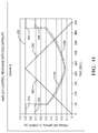
- FIG. 11 shows Graph 6, which depicts plots of air simulating refrigerant at compressor discharge, crankcase, and suction pressures 202, 204, 206, respectively, in an air conditioning system utilizing a eCV 120 under the same operating conditions experienced in generating the plotted data of FIG. 10 , as the control current is increased from zero to 0.9 A, and back again to zero.
- the valve train control response to the PWM signals demonstrated by crankcase and suction pressure curves 204 and 206 is substantially devoid of discontinuities.
- the NMD 122 precludes bouncing of the valve train 128 off of the valve seat in a eCV 120 at control current levels between the range of zero and 0.9 A, and provides a smooth, predictable control response between these minimum and maximum control current levels, thereby improving performance and reliability relative to the prior eCV 20.
Landscapes
- Engineering & Computer Science (AREA)
- General Engineering & Computer Science (AREA)
- Mechanical Engineering (AREA)
- Magnetically Actuated Valves (AREA)
Description
- This application claims the benefit under Title 35, U.S.C. § 119(e) of
U.S. Provisional Patent Application Serial No. 61/484,250 - The present disclosure relates to electronic control valve having a noise mitigation device according to the preamble of
claim 1. An electronic control valve of this kind is known fromUS 6 474 572 B1 . In this known electronic valve the mass is arranged in a bore, which is provided in the valve stationary portion. A first biasing means is disposed between said mass and said valve stationary portion, and a second biasing means is disposed between said mass and the valve train movable member. FromUS 5 352 101 A another electronic control valve is known, in which all components of the noise mitigation device are arranged separately from the valve train movable member and outside of the valve train movable member. - An electronic control valve (eCV) generates an undesirable audible noise over a given supply current range. This noise is caused by the moving portion of the valve, i.e., the valve train, repetitively impacting a stationary portion of the valve, e.g., the valve seat.
- An eCV may be used, for example, in an automotive air conditioning system to control compressor capacity by regulating gas entering the compressor crankcase. A prior such eCV is shown in
FIG. 1 . Higher eCV supply current increases compressor capacity and lower eCV supply current decreases compressor capacity. The eCV current can be changed by changing the applied voltage. In the case of today's vehicles, the applied voltage is changed by pulsing battery voltage on and off, typically at 400 Hz. One 400 Hz cycle is 2.5 milliseconds. Thus, a 400 Hz eCV is regulated through pulse width modulation (PWM), i.e., by altering the portion of each 2.5 millisecond period (the PWM cycle) that a voltage pulse is present. Duty cycle is the time fraction of the PWM cycle that the eCV is energized. The duty cycle represents that time fraction of each PWM cycle during which an energizing voltage pulse is present as a percentage, with average voltage and current increasing as a function of an increased duty cycle. At 50% duty cycle, full voltage is applied for 1.25 milliseconds and no voltage is applied for 1.25 milliseconds. Audible eCV noise is greatest near 50% duty cycle because the valve train can be driven at its maximum displacement in both directions. When energized, the eCV is activated and the actuating magnetic field of the valve pushes against the valve train inertia and a return spring. When the actuator is de-energized, the eCV is unactivated and the return spring pushes the valve train back towards its off-mode rest position. At low duty cycle the valve train has less time to accelerate toward the valve seat. At high duty cycle, the valve train has less time to accelerate back towards its rest position. With lower displacement, the valve train velocity is lower and cannot impact the valve seat with such a high contact force. - The eCV must be a very low friction device to function properly. Conceptually, a good eCV design approaches a classic spring mass system which is frictionless and has very low damping. The result is relatively high amplitude valve train cyclic motion excited by the supply voltage frequency, also known as the forcing frequency. At around 50% duty cycle the valve train repetitively strikes the valve seat at the frequency of the supply voltage with high velocity. The repetitive impact creates an audible, undesirable buzzing noise.
- This noise is a function of, but not limited to: supply voltage frequency; coil inductance; valve train mass; valve train return spring force; valve train damping; and valve seat geometry. Prior efforts to minimize this valve noise in automotive applications include: changing coil inductance by increasing coil size; changing supply voltage frequency; changing supply voltage waveform characteristics; adding friction by direct contact between the valve train and valve body; suppressing noise transmission through air and structure; changing valve seat impact zone compliance; changing valve train mass; and changing valve train return spring force.
- Some such efforts have proven somewhat effective, but have not been successful in satisfactorily resolving the problem for various reasons. Changing coil inductance by increasing coil size is effective, but increases cost and packaging. Changing supply voltage frequency or waveform characteristics is effective, but is not acceptable to most customers. Adding friction by direct contact between the valve train and valve body is effective, but negatively impacts valve performance and has proven unpredictable during valve operation. Suppressing noise transmission through air and structure is partially effective, but increases cost and negatively impacts durability and packaging. Changing valve seat impact zone compliance is effective, but negatively impacts performance and durability. Changing valve train mass or return spring force has not been effective within reasonable limits.
- In practice, prior attempts to solve this problem by eCV suppliers have primarily involved adding direct contact friction between the valve train and valve body via various methods such as: adding grease between the valve train and valve body; utilizing an O-ring to provide friction between valve train and valve body; and configuring the actuating magnetic field to be non-symmetrical, whereby the field induces a friction-generating side load between valve train and valve body. As noted above, however, introducing friction directly between the valve train and the valve body impairs valve performance and introduces performance unpredictably.
- A noise mitigation device that overcomes the shortcomings of the above-discussed prior efforts would be a desirable advancement in the relevant art.
- The integration of a non-contact noise mitigation device (NMD) eliminates undesirable eCV noise by reducing the supply voltage frequency induced valve train reciprocating motion. This device is directly coupled to the noise source.
- The integral, non-contact NMD does not rely on unpredictable friction. Instead it mitigates primary drive frequency effects by dynamically reducing valve train reciprocation motion. In other words, the NMD serves as a dynamic motion absorber or reducer. The NMD opposes the valve train motion with a mass in transient motion approximately 180° out of phase with the valve train motion. The NMD includes a mass that is connected to the valve train by biasing means (e.g., a spring or spring system) that transmits forces between the NMD mass and the valve train along the axis of the valve train motion. The biasing means may include solid, liquid, or gas components capable of storing and transferring mechanical energy. The exemplary embodiments herein illustrated employ one or more coil springs as the biasing means.
- The present invention provides an electronic control valve according to claim 1 a valve stationary portion defining a substantially central bore extending along an axis of the valve, and a valve train including a movable member of the valve. The valve train moveable member is disposed in the central bore, and the valve train is adapted for reciprocal movement along the axis. A mass is engaged with the valve train and adapted for reciprocal movement along the axis. A biasing means is disposed between the valve train and the mass. Reciprocal movements of the mass along the axis induced by forces exerted along the axis by the valve train are transmitted through the biasing means, whereby reciprocal movement of the valve train along the axis is dynamically reduced by the mass.
- The above-mentioned and other features and objects of the invention, and the manner of attaining them, will become more apparent, and the invention itself will be better understood, by reference to the following description of an exemplary embodiment of the invention representing its best mode, taken in conjunction with the accompanying drawings, wherein:
-
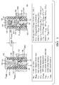
FIG. 1 is a cross-sectioned horizontal view of a prior eCV; -
FIG. 2A is an enlarged, vertical view of outlinedarea 2 ofFIG. 1 , showing an eCV according to a first embodiment of the present invention having an NMD with dual biasing means; -
FIG. 2B is similar toFIG 2A , showing an eCV according to a second embodiment of the present invention having an NMD with a single biasing means; -
FIG. 3 provides partial views of the first embodiment eCV ofFIG. 2A , showing the mass at its limits of travel, and indicating parameters used in tuning the NMD to a particular valve forcing frequency; -
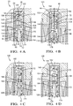
FIG. 4A is a fragmented, cross-sectional view of a vertically-oriented eCV according to the first embodiment showing the eCV (and its containing, unshown air conditioning system) off, with its valve train and NMD at rest; the views ofFIGS. 4B-4E are similar toFIG. 4A but at different stages of valve operation; -
FIG. 4B is a view of the activated eCV at the beginning of its first cycle of operation, during the energized portion of the PWM cycle, showing the valve train moving downwardly relative to the valve body and the mass still at rest, the mass inertia exerting an upward force on the valve train through the upper biasing means; -
FIG. 4C is a view of the unactivated eCV at the middle of its first cycle of operation, during the de-energized portion of the PWM cycle, showing the valve train moving upwardly under the influence of its return spring and the mass continuing downward movement against the force of the lower biasing means; -
FIG.4D is a view of the unactivated eCV at the end of its first cycle of operation, showing the valve train at the upward end of its reciprocating movement, with the mass inertia exerting a downward force on the valve train through the lower biasing means; -
FIG. 4E is a view of the activated eCV at the beginning of its second cycle of operation, showing the valve train moving downwardly and the mass at the upward end of its reciprocating movement, with the mass inertia exerting an upward force on the valve train through the upper biasing means; -
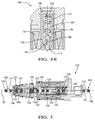
FIG. 5 is a cross-sectioned horizontal view of an eCV according to the present invention schematically indicating alternative locations for an NMD, which is shown according to the first embodiment; -
FIG. 6 showsGraph 1, which shows the sound pressure spectra of the prior eCV ofFIG. 1 installed in the air conditioning system of a test vehicle and operated at a forcing frequency of 400 Hz; -
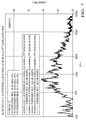
FIG. 7 showsGraph 2, which shows the sound spectra of three eCVs according to the first embodiment of present invention, each nominally tuned to a forcing frequency of 400Hz and tested at conditions identical to those which produced the prior eCV results shown in Graph 1 (FIG. 6 ); -
FIG. 8 showsGraph 3, which shows the sound spectra of the prior eCV when tested at an eCV forcing frequency of 458Hz; -
FIG. 9 showsGraph 4, which shows the sound spectra of the three eCVs according to the first embodiment nominally tuned to 400 Hz when tested at an off-design forcing frequency of 458Hz; -
FIG 10 showsGraph 5, which indicates various simulated refrigeration system pressures over time when equipped with a prior PWM-controlled eCV operating at 400 Hz, as the prior eCV's average control current level increases and decreases between minimum and maximum values, indicating discontinuities in the valve train control response; and -
FIG. 11 showsGraph 6, which is similar to Graph 5 (FIG. 10 ) but indicating various simulated refrigeration system pressures over time when equipped with an eCV according to the present invention operating under the conditions that produced the results shown inGraph 5, as the inventive eCV's average control current level increases and decreases between minimum and maximum values, demonstrating the valve train control response being substantially devoid of the discontinuities exhibited with the prior eCV. - Corresponding reference characters indicated corresponding parts throughout the several views. Although the drawings represent an embodiment of the present invention, the drawing are not necessarily to scale or to the same scale and certain features may be exaggerated in order to better illustrate and explain the present invention.
-
FIG. 1 shows aprior eCV 20 of a known, commercially available type that operates in the above-described manner, for use in the air conditioning system (not shown) of an automobile. Although shown horizontally oriented, the prior and inventive eCVs disclosed herein may be oriented otherwise, and the effects of gravity on the valve train and NMD are herein ignored. TheeCV 20 includes avalve body 22 having stationary portions and acentral bore 24 that extends along anaxis 26. Inside thevalve body 22 is anelongate valve train 28 slidably disposed in thebore 24 and having reciprocating movement along theaxis 26 relative to the stationary portions of thevalve body 22. Surrounding thecentral bore 24 and extending along theaxis 26 is acylindrical activation coil 30 that is intermittently energized with battery voltage during eCV operation at the forcing frequency, which is typically 400 Hz. - Included among the members of the
valve train 28 is anelongate shaft 32 fixed to and interconnecting other members of the valve train. Included among the other valve train members is a generally cylindrical,ferrous plunger 34 affixed to one end of theshaft 32. Theplunger 34 is driven leftwardly, as viewed inFIG. 1 , along theaxis 26 towards avalve seat 36, by the magnetic actuating field generated by thecoil 30 when theeCV 20 is electrically activated. Thevalve seat 36 is a stationary portion of thevalve body 22 and thesite 38 wherevalve train 28 impacts thevalve body 22 in theprior eCV 20. - Referring still to
FIG. 1 , theshaft 32 is radially supported by thecentral bore 40 of a stationary, cylindrical bearingmember 42 of thevalve body 22. The bearingmember 42 is a stationary part of thevalve body 22. Theplunger 34 and the bearingmember 42 are disposed within a stationary,tubular cage member 44, the rightward end of which has alateral wall 46. A portion of thecage member 44 is surrounded by thecoil 30. The circumferential outer surface of theplunger 34 slidably engages, or has a slight clearance to, the cylindrical interior surface of thecage member 44. - Referring still to
FIG. 1 , the bearingmember 42 is provided with acounterbore 50 in which is disposed oneend 52 of areturn spring 54. Thereturn spring 54 is a compression coil spring having axially opposite ends and which surrounds theshaft 32. Theother end 56 of thereturn spring 54 abuts theplunger 34, and thereturn spring 54 thus biases theplunger 34 rightwardly along theaxis 26 toward its rest position. The magnetic actuating force urges thevalve train 28 leftward against the biasing force of thereturn spring 54 and towards thevalve seat 36. - As herein described and/or shown in accompany
FIGS. 2A-5 , aneCV 120 according to the present invention structurally differs from theprior eCV 20. In the first and second embodiments discussed in detail herein, certain portions of theprior eCV 20 shown in the outlinedarea 2 ofFIG. 1 are replaced with components that define anNMD 122.FIGS. 2A and 2B are enlarged views of the outlinedarea 2, respectively showing the relevant portions of first and second embodiments ofeCV 120. Thefirst embodiment eCV 120 is also referred to herein aseCV 120A. Thesecond embodiment eCV 120 is also referred to herein aseCV 120B. Components of theeCV 120 distinguishably configured relative to the first andsecond embodiments eCV - Each
NMD 122 includes amass 124 having reciprocating motion along theaxis 26, and at least one biasing means through which themass 124 and thevalve train 128 interact. Other than as discussed herein or shown in the accompanying drawings, the valve trains 128 of the first and second embodiments of theeCVs 120 are substantially similar to thevalve train 28 of theprior eCV 20. In the first and second embodiments of theeCV 120, thevalve train plungers 130 affixed to theshaft 32 are provided with a largecentral bore 132 in which theNMD 122 is disposed. TheNMD mass 124 may, in some embodiments (not shown), be provided with an axially-extending through hole or channel through which fluid may be vented between opposite axial ends of the mass, which may help to facilitate its axial movement. - Referring to
FIG. 2A , thefirst embodiment eCV 120A includes anNMD 122A including amass 124A located between first and second biasing means 134 and 136, respectively. Themass 124A is substantially cylindrical and provided with axially opposingfaces plungers 130 of the first andsecond embodiment eCVs 120 include a surface within thebore 132A that interfaces themass 124A. Theplunger 130A ofeCV 120A includes asurface 142A, shown inFIG. 3 , that interfaces themass face 138A. Thus, the first biasing means 134 is disposed in afirst chamber 144 defined between a pair of interfacingsurfaces axis 26. Thefirst chamber 144 is shown inFIG. 3 . With continued reference toFIG. 3 , theplunger 130A includes acylindrical cap 146 affixed to the open end of itscentral bore 132A. Theplunger cap 146, which may or may not be provided with an axially-extending fluid vent hole (not shown), includes asurface 148 that interfaces themass face 140A. Thus, the second biasing means 136 is disposed in asecond chamber 150 defined between a pair of interfacingsurfaces - In the shown
first embodiment eCV 120A, the biasing means 134 and 136 are coil compression springs, but the biasing means 134, 136 may alternatively be fluid-type springs that respectively engage the paired surfaces 138A, 142A, and 140A, 148. Various, suitable types of biasing means 134 and/or 136 are represented schematically inFIG. 5 discussed further hereinbelow. - With continued reference to
FIG. 3 , in the depictedfirst embodiment eVC 120A, thesprings cylindrical mass 124A have recessedportions surface 142A is defined by theend 160 of theshaft 32, and thecap surface 148 has a recessedportion 162, about which and in which are disposed the second ends 158 of thesprings - Referring to
FIG. 2B , thesecond embodiment eCV 120B includes anNMD 122B including a mass 124B that is engaged by a single biasing means. As shown inFIG. 2B , the biasing means is thespring 134. Thefirst end 156 of thespring 134 is retained about a projectingportion 164 of the firstmass face 138B, and thesecond end 158 of thespring 134 is retained about theshaft end 160 and retained relative to theplunger surface 142B. In thesecond embodiment eCV 120B, thespring 134 may be in compression or tension. Thus, in theeCV 120B, the biasing means 134 is disposed in achamber 144 defined between a pair of interfacingsurfaces axis 26. The opposing masssecond face 140B defines a free end of the mass 124B. - The NMDs of the
first embodiment eCV 120A, thesecond embodiment eCV 120B, and other embodiments not herein depicted and utilizing other types of biasing means, are tuned to a particular forcing frequency (e.g., 400 Hz) by similar methods. For the purposes of illustration, however, the description of a method of tuning and the eCV operation that follows is with reference to thefirst embodiment eCV 120A. - The mass of the valve train 128 (MVT) and its displacement (ΔXVT) along the
axis 26 may be known parameters, and the selected limits of the NMD mass displacement (ΔXNMD) along theaxis 26 may be selected based on packaging constraints. The NMD is designed to have a natural frequency (fnNMD) equal to the known supply voltage frequency (ffvt, e.g., 400 Hz) and to exert a force (FNMD) on thevalve train 128 when the mass displacement (ΔXNMD) is 180° out of phase with the valve train displacement (ΔXVT). With reference toFIG. 3 , which shows only a portion of thevalve train 128 and its mass (MVT), to tune theNMD 120 for a typical eCV application, the parameters of the NMD mass (MNMD) and spring system stiffness (KNMD) must be determined; they may be calculated by the following method: - MNMD =
mass 124 of theNMD 122 - MVT = mass of valve train 128 (known, and excludes the NMD mass 124)
- KNMD = spring system stiffness (e.g., springs 134, 136) of the
NMD 122 - ΔXVT = displacement of the
valve train 128 along the axis 26 (known) - ΔXNMD = displacement of the
NMD mass 124 along the axis 26 (selected) - FNMD = force exerted by the
NMD 122 on thevalve train 128 - ffvt = supply voltage frequency (forcing frequency, known)
- fnNMD = natural frequency of the
NMD 122 -
-


-
FIGS. 4A-4E show theeCV 120 cycling and the resulting reaction of theNMD mass 124.FIG. 4A shows theNMD mass 124 at rest, with the eCV activating voltage off. InFIG. 4A , thedistance 170 in a direction parallel with theaxis 26 betweensurfaces distance 172 in a direction parallel with theaxis 26 betweensurfaces mass 124 supported in an equilibrium position by the spring system, which includessprings FIG. 4A , thevalve train 128 is supported by thereturn spring 54 in its resting position, and thegap 174 between the downward-facingsurface 176 of theplunger 130 and the interfacing, upward-facingsurface 178 of the bearingmember 42 is large. -
FIG. 4B shows theeCV 120 at the beginning of its first cycle, with the eCV activating voltage applied to thecoil 30. As thevalve train 128 starts to move downwardly (as indicated by the arrow 180) due to the supply voltage application to thecoil 30, theNMD mass 124 will tend to remain at rest due to its inertia effects. Thus, relative toFIG. 4A , thedistance 170 increases and thedistance 172 decreases, as indicated by the + and - signs, respectively, and thegap 174 is somewhat smaller, as indicated by the - sign. TheNMD mass 124 will eventually move downwardly due to the force exerted on it by the spring system while at the same time, theNMD mass 124 exerts an equal and opposite upward force, indicated byarrow 182, on thevalve train 128 through the spring system. -
FIG. 4C shows theeCV 120 at the middle of its first cycle, with the eCV activating voltage off. Thereturn spring 54 forces thevalve train 128 in the upward direction (indicated by the arrow 184), while themass 124 continues its downward movement. Thus, relative toFIG. 4B , thedistance 170 decreases and thedistance 172 increases, as indicated by the - and + signs, respectively, and thegap 174 is somewhat larger, as indicated by the + sign. TheNMD mass 124 exerts an opposite downward force, indicated byarrow 186, through the spring system opposing the upward motion of thevalve train 128. -
FIG. 4D shows theeCV 120 at the end of its first cycle, with the eCV activating voltage still off. Thevalve train 128 has reached a position at the upward end of its travel in this cycle; themass 124 is near the downward end of its travel in this cycle, and exerts a downward force on thevalve train 128, indicated byarrow 188, through the spring system. Relative toFIG. 4C , thedistance 170 decreases and thedistance 172 increases, as indicated by the - and + signs, respectively, and thegap 174 is somewhat larger, as indicated by the + sign. The size of thegap 174 inFIG. 4D , though large, may differ from thelarge gap 174 shown inFIG. 4A . -
FIG. 4E shows theeCV 120 at the beginning of its second cycle, as the eCV activating voltage is applied. As thevalve train 128 starts to move downwardly (as indicated by the arrow 190) due to the supply voltage application to thecoil 30, theNMD mass 124 approaches the upward end of its movement. Thus, relative toFIG. 4D , thedistance 170 increases and thedistance 172 decreases, as indicated by the + and - signs, respectively, and thegap 174 is somewhat smaller, as indicated by the - sign. InFIG. 4E , themass 124 exerts an upward force through the spring system on thevalve train 128, indicated byarrow 192, that tends to oppose the actuating force imparted on theplunger 130 by the electromagnetic field, thereby slowing the downward movement of thevalve train 128 towards the valve seat 36 (FIG. 1 ). Impact between the valve train and the valve seat is softened or altogether avoided due to the shorter valve train displacement, slower valve train velocity, reduced valve train momentum at the time of impact, and/or cessation of the activating voltage application to the coil during the longer travel time of the valve train in the direction of the valve seat. Thus, the undesirable, audible noise associated with moving members of the valve train repeatedly impacting stationary portions of the valve body is mitigated by the NMD. - It is to be understood that, for a cyclically applied forcing function, the result is to reduce, but not eliminate, the overall reciprocating motion of the
valve train 128 necessary for operation of theeCV 120. The resultant decreased valve train displacement and/or velocity significantly reduces the impact of the valve member on the valve seat, dramatically mitigating the audible noise level during normal operation. - The
NMD 122 can be installed anywhere in aeCV 120 as long as it is constrained by the eCV along theaxis 26 ofvalve train 128 travel.FIG. 5 shows six such positions, some of which are internal to the valve body central bore 24, some of which are external to thebore 24. Embodiments of theNMD 122 located outside of the valve body bore may be disposed externally of thevalve body 22, and coupled to thevalve train 128 via an axially moveable valve train portion extending axially from the valve body and engaging the biasing means of theNMD 120. As noted above, the biasing means shown schematically inFIG. 5 may be any of various, suitable types such as, for example, compression or tension springs, such as above-discussedsprings 134 and/or 136, or fluid-type springs. Moreover, though dual biasing means are shown in eachNMD 122 ofFIG. 5 , it is to be understood that any of them may include only a single biasing means. - The effectiveness of the
NMD 122 at mitigating noise in aneCV 120 when tuned to its forcing frequency has been demonstrated. Samples of the NMD have been built, existing eCVs modified therewith, and the prototype eCVs tested. The NMDs were designed with a resonant frequency of 400 Hz. They were intended to function optimally at 400 Hz, which is the most common eCV supply voltage forcing frequency. -
Graph 1, shown inFIG. 6 , shows the sound pressure spectra of a prior eCV representative of current eCV technology (shown inFIG. 1 ) installed in the air conditioning system of a test vehicle and operated at a forcing frequency of 400 Hz. The sound pressure was measured outside of the test vehicle. There are multiple discrete peaks in the amplitude of the noise spectra at multiples of the 400Hz forcing frequency, which is a characteristic of audible buzz noise. -
Graph 2, shown inFIG. 7 , shows the sound spectra of three eCVs according to the first embodiment, each equipped with a prototype dynamic absorber (i.e., the NMD) nominally tuned to a forcing frequency of 400Hz. These three eCVs were tested at conditions identical to those of the prior eCV that produced the results shown in Graph 1 (FIG. 6 ). These three eCVs were subjectively quieter than the prior eCV whose test results are shown inGraph 1. Those of ordinary skill in the art will appreciate that these three eCVs did not exhibit the characteristic spectra of audible buzz noise reflected inGraph 1. -
Graph 3, shown inFIG. 8 , shows the sound spectra of the prior eCV (previously tested at a 400 Hz forcing frequency, seeGraph 1,FIG. 6 ) when tested at a forcing frequency of 458Hz. Those of ordinary skill in the art will notice that the multiple discrete peaks in the amplitude of the noise spectra are now at multiples of the 458Hz forcing frequency, which is another characteristic of audible buzz noise. -
Graph 4, shown inFIG. 9 , shows the sound spectra of the three eCVs according to the first embodiment nominally tuned to 400 Hz (previously tested at a 400 Hz forcing frequency, seeGraph 2,FIG. 7 ) when tested at a forcing frequency of 458Hz. As expected, compared to its performance when activated at the 400 Hz forcing frequency, the dynamic valve train motion absorber (i.e., the NMD) is not as effective at reducing the audible buzz noise when activated at off-design forcing frequency conditions. - A known phenomena of prior eCVs such as
eCV 20 ofFIG. 1 , which typically operate under 400 Hz PWM cycles, is that the valve train fails to obey the PWM control signals within a narrow duty cycle range. The preferred 400 Hz PWM schema is a compromise between lower frequency systems which result in greater valve train travel and higher noise levels, and higher frequency systems which generate relatively less valve train travel and noise, but often cause the valve to stick, resulting in performance and reliability issues. Consequently, OEM customers have adopted and continue to specify 400 Hz PWM systems for actuating refrigerant system eCVs. - At 400 Hz, however, prior eCVs typically experience operating points at which the valve train fails to obey the activating PWM signals; at such points, which may be a relatively narrow subrange of control current values, there is a control response discontinuity. The operating points at which the control response discontinuities occur may actually be narrow subranges of control current values in the much larger range between the minimum and maximum control current values. In other words, at such operating points, there is a discontinuity between the electrical control signals received at the
coil 30 of theprior eCV 20, and the mechanical response by itsvalve train 28. Notably, the control response discontinuity issue is not as pronounced as lower and higher PWM cycle frequencies. Those frequencies, however, have attendant noise and valve sticking issues, as discussed above. It is believed that, in a 400 Hz PWM system, the control discontinuity results from thevalve train 28 impacting thevalve seat 36 such that it bounces off of the seat at these operating points or narrow duty cycle ranges, the bouncing of thevalve train 28 overriding the desired control response at the duty cycle(s) corresponding to the time-averaged activating current level(s). The inadvertent bouncing of the valve train affects the control properties of theeCV 20, impairing performance and generating additional noise. It has been discovered that, in addition to the above-identified objectives and advantages of the present invention, theeCV 120 addresses the control response discontinuity issue. -
FIG. 10 showsGraph 5, which depicts plots of various air pressures simulating refrigerant pressures in an air conditioning system having a prior 400 Hz PWM eCV, such aseCV 20 ofFIG. 1 , located on the suction side of the refrigeration compressor. The plots are over a 450 second period during which the time-averaged control current, represented bycurve 200, is linearly increased from a minimum or zero amps (A) corresponding to a zero percent duty cycle, to a maximum of 0.9 A corresponding to a 100 percent duty cycle, and back again to zero. Air pressures simulating refrigerant at compressor discharge, crankcase, and suction pressures are plotted ascurves areas 208 ofFIG. 10 are clear areas of suction and crankcase pressure fluctuations incurves -
FIG. 11 showsGraph 6, which depicts plots of air simulating refrigerant at compressor discharge, crankcase, andsuction pressures eCV 120 under the same operating conditions experienced in generating the plotted data ofFIG. 10 , as the control current is increased from zero to 0.9 A, and back again to zero. The valve train control response to the PWM signals demonstrated by crankcase and suction pressure curves 204 and 206 is substantially devoid of discontinuities. These results demonstrate that aneCV 120 provides the additional advantage of solving the prior known issue of valve train control response discontinuities in 400 Hz PWM systems. It is believed that theNMD 122 precludes bouncing of thevalve train 128 off of the valve seat in aeCV 120 at control current levels between the range of zero and 0.9 A, and provides a smooth, predictable control response between these minimum and maximum control current levels, thereby improving performance and reliability relative to theprior eCV 20. - While this invention has been described in terms of a preferred, exemplary embodiment thereof, it may be further modified within the scope of its disclosure to the extent set forth in the claims that follow. This application is therefore intended to cover any variations, uses, or adaptations of the invention using its general principles. Further, this application is intended to cover such departures from the present disclosure as come within know or customary practice in the art to which this invention pertains.
Claims (15)
- An electronic control valve (120), comprising:a valve stationary portion defining a substantially central bore (40) extending along an axis (26) of said valve (120);a coil (30) adapted when energized to generate a magnetic field,a valve train (128) including a valve train movable member comprising a shaft (32) disposed in said central bore (40) and a ferrous plunger (130) affixed to an end of the shaft (32), the plunger (130) being driven by said magnetic field, so that said valve train (128) is adapted for reciprocal movement along said axis (26),a noise mitigation device (122) includinga mass (124) arranged in said central bore (132) and having reciprocating motion along the axis (26), andat least one biasing means (134, 136) through which the mass (124) and the valve train (128) interact, said at least one biasing means (134, 136) being disposed between said valve train (128) and said mass (124), so that reciprocal movements of said mass (124) along said axis (26) induced by forces exerted along said axis (26) by said valve train (128) and transmitted through said at least one biasing means (134, 136) dynamically reduce the reciprocal movement of said valve train (128) along said axis (26),characterized in that
said mass (124) and said at least one biasing means (134, 136) are carried by said valve train movable member (130), and said at least one biasing means (134, 136) is retained about said mass (124) and said valve train movable member (130). - The electronic control valve (120) of claim 1, wherein said biasing means comprises a spring (134, 136) disposed between interfacing surfaces (138, 140, 142, 148) of said mass (124) and said valve train (128).
- The electronic control valve (120) of claim 2, wherein said spring (134, 136) has opposite first and second ends (156, 158) spaced along said axis (26), said spring first end (156) engaged with a first surface (138, 140) located on said mass (124), said spring second end (158) engaged with a second surface (142, 148) located on said valve train (128).
- The electronic control valve (120) of claim 1, wherein said at least one biasing means comprising a first biasing means (134) disposed between a first pair of interfacing surfaces (138, 142) of said mass (124) and said valve train (128), and further comprising a second biasing means (136) disposed between said valve train (128) and said mass (124), reciprocal axial movements of said mass (124) induced by axial forces exerted by said valve train (128) transmitted through said second biasing means (136).
- The electronic control valve (120) of claim 4, wherein said first biasing means comprises a first spring (134) having a pair of opposite ends (156, 158) spaced along a direction parallel with said axis (26), and said second biasing means comprises a second spring (136) having a pair of opposite ends (156, 158) spaced along a direction parallel with said axis (26), said second spring (136) disposed between interfacing surfaces (140, 148) of said mass (124) and said valve train (128).
- The electronic control valve (120) of claim 5, wherein said second spring (136) is disposed between a second pair of interfacing surfaces (140, 148) of said mass (124) and said valve train (128).
- The electronic control valve (120) of claim 5, wherein said second spring (136) has a pair of opposite ends (156, 158) spaced along said axis (26), one of said second spring ends (156) engaged with a third surface (140) located on said mass (124), the other of said second spring ends (158) engaged with a fourth surface (148) located on said valve train (128).
- The electronic control valve (120) of claim 7, wherein said mass first and third surfaces (138, 140) are spaced along said axis (26), and said first and second springs are compression coil springs (134, 136).
- The electronic control valve (120) of claim 4, wherein said second biasing means (136) is disposed between a second pair of interfacing surfaces (140, 148) of said mass (124) and said valve train (128).
- The electronic control valve (120) of claim 1, wherein said mass (124) and said valve train (128) define a chamber (144, 150) of variable volume containing said biasing means (134, 136).
- The electronic control valve (120) of claim 1, wherein said mass (124) is located outside of said central bore (40).
- The electronic control valve (120) of claim 11, wherein said at least one biasing means (134, 136) is located outside of said central bore (40).
- The electronic control valve (120) of claim 1, wherein reciprocal movement of said valve train (128) along said axis (26) is opposed by inertia-induced forces transmitted between said mass (124) and said valve train (128) through said biasing means (134, 136).
- The electronic control valve (120) of claim 1, wherein reciprocal movement of said valve train (128) along said axis (26) is partially a mechanical response to electromagnetic forces exerted on said valve train (128), said electromagnetic forces generated by pulsed electrical signals of variable duration having a range of time-averaged control current levels (200) corresponding to electrical signal pulse lengths over a cycle, whereby said valve train (128) has a control response (204, 206) to changes in control current levels (200) within said range, said control response (204, 206) substantially devoid of discontinuities (208) over said range.
- The electronic control valve (120) of claim 14, wherein said range of control current levels (200) extends from a minimum value corresponding to a pulse duration of zero percent of said cycle and a maximum value corresponding to a pulse duration of 100 percent of said cycle.
Applications Claiming Priority (3)
| Application Number | Priority Date | Filing Date | Title |
|---|---|---|---|
| US201161484250P | 2011-05-10 | 2011-05-10 | |
| US13/467,511 US20120305822A1 (en) | 2011-05-10 | 2012-05-09 | Electronic control valve having an integral non-contact noise mitigation device |
| PCT/US2012/037256 WO2012154924A1 (en) | 2011-05-10 | 2012-05-10 | Electronic control valve having an integral non-contact noise mitigation device |
Publications (3)
| Publication Number | Publication Date |
|---|---|
| EP2707599A1 EP2707599A1 (en) | 2014-03-19 |
| EP2707599A4 EP2707599A4 (en) | 2014-12-31 |
| EP2707599B1 true EP2707599B1 (en) | 2016-09-14 |
Family
ID=47139652
Family Applications (1)
| Application Number | Title | Priority Date | Filing Date |
|---|---|---|---|
| EP12782199.9A Not-in-force EP2707599B1 (en) | 2011-05-10 | 2012-05-10 | Electronic control valve having an integral non-contact noise mitigation device |
Country Status (4)
| Country | Link |
|---|---|
| US (2) | US20120305822A1 (en) |
| EP (1) | EP2707599B1 (en) |
| CN (1) | CN103547799B (en) |
| WO (1) | WO2012154924A1 (en) |
Families Citing this family (3)
| Publication number | Priority date | Publication date | Assignee | Title |
|---|---|---|---|---|
| JP2016125376A (en) * | 2014-12-26 | 2016-07-11 | 株式会社テージーケー | Control valve for variable displacement compressor |
| AT517391B1 (en) * | 2015-07-03 | 2018-11-15 | Sonderhoff Eng Gmbh | valve means |
| CN107606235B (en) * | 2017-09-25 | 2023-10-03 | 珠海格力节能环保制冷技术研究中心有限公司 | Control valve structure and compressor with same |
Citations (1)
| Publication number | Priority date | Publication date | Assignee | Title |
|---|---|---|---|---|
| US6474572B1 (en) * | 1999-04-13 | 2002-11-05 | Hitachi, Ltd. | Fuel-injection valve |
Family Cites Families (14)
| Publication number | Priority date | Publication date | Assignee | Title |
|---|---|---|---|---|
| US3446473A (en) * | 1964-11-23 | 1969-05-27 | Monsanto Co | Pulsed solenoid control valves |
| US5352101A (en) * | 1992-10-05 | 1994-10-04 | Aura Systems, Inc. | Electromagnetically actuated compressor valve |
| US7063511B2 (en) * | 2003-07-28 | 2006-06-20 | Delphi Technologies, Inc. | Integrated control valve for a variable capacity compressor |
| CN101503996A (en) * | 2005-02-28 | 2009-08-12 | 株式会社不二工机 | Control valve for variable capacity compressor |
| JP4865703B2 (en) * | 2005-04-08 | 2012-02-01 | イーグル工業株式会社 | Capacity control valve |
| US7422193B2 (en) * | 2005-08-31 | 2008-09-09 | Emerson Electric Co. | Solenoid valve |
| CN101410620B (en) * | 2006-03-15 | 2011-03-23 | 伊格尔工业股份有限公司 | Capacity control valve |
| EP2000670B1 (en) * | 2006-03-29 | 2018-07-25 | Eagle Industry Co., Ltd. | Control valve for variable displacement compressor |
| JP4695032B2 (en) * | 2006-07-19 | 2011-06-08 | サンデン株式会社 | Volume control valve for variable capacity compressor |
| DE102006038920B4 (en) * | 2006-08-18 | 2013-01-31 | Pierburg Gmbh | Vibration and pulsation damped electro-pneumatic converter |
| US8720213B2 (en) * | 2008-02-19 | 2014-05-13 | Delphi Technologies, Inc. | Variable displacement compressor with a compensated suction shufoff valve |
| US20100143162A1 (en) * | 2008-12-10 | 2010-06-10 | Delphi Technologies, Inc. | Suction shutoff valve |
| DE102009041188A1 (en) * | 2009-09-14 | 2011-03-24 | Svm Schultz Verwaltungs-Gmbh & Co. Kg | Electromagnet with an anchor |
| DE102009046822A1 (en) * | 2009-11-18 | 2011-05-19 | Robert Bosch Gmbh | Switching valve with a valve element movable in a housing |
-
2012
- 2012-05-09 US US13/467,511 patent/US20120305822A1/en not_active Abandoned
- 2012-05-10 EP EP12782199.9A patent/EP2707599B1/en not_active Not-in-force
- 2012-05-10 WO PCT/US2012/037256 patent/WO2012154924A1/en not_active Ceased
- 2012-05-10 CN CN201280022409.2A patent/CN103547799B/en not_active Expired - Fee Related
-
2015
- 2015-02-23 US US14/628,634 patent/US9309987B2/en not_active Expired - Fee Related
Patent Citations (1)
| Publication number | Priority date | Publication date | Assignee | Title |
|---|---|---|---|---|
| US6474572B1 (en) * | 1999-04-13 | 2002-11-05 | Hitachi, Ltd. | Fuel-injection valve |
Also Published As
| Publication number | Publication date |
|---|---|
| US20120305822A1 (en) | 2012-12-06 |
| WO2012154924A1 (en) | 2012-11-15 |
| CN103547799A (en) | 2014-01-29 |
| CN103547799B (en) | 2017-08-04 |
| EP2707599A4 (en) | 2014-12-31 |
| US9309987B2 (en) | 2016-04-12 |
| US20150167859A1 (en) | 2015-06-18 |
| EP2707599A1 (en) | 2014-03-19 |
Similar Documents
| Publication | Publication Date | Title |
|---|---|---|
| US7828265B2 (en) | Solenoid valve | |
| US9309987B2 (en) | Electronic control valve having an integral non-contact noise mitigation device | |
| EP0055518A1 (en) | Solenoid valve | |
| EP3088726B1 (en) | High-pressure fuel supply pump | |
| EP1985857A2 (en) | Solenoid pump | |
| CN105684121B (en) | Electromagnetic switch with damping interface | |
| US20090013944A1 (en) | Device for controlling the movement of a valve, in particular of an intake valve, of an internal combustion engine | |
| EP3358175A1 (en) | High-pressure fuel pump and control device | |
| JP2019203589A (en) | Electromagnetic valve and refrigeration cycle | |
| US20190072148A1 (en) | Damping force variable valve | |
| JP7012465B2 (en) | Configuration with a valve to regulate the fluid | |
| US20070138719A1 (en) | Fluid-filled type active vibration damping device | |
| CN109996983B (en) | Multi-way valve and actuator comprising such a multi-way valve | |
| EP2783114B1 (en) | Linear driving unit with a resonant spring and a deformation control device | |
| EP3059445B1 (en) | Electromagnetic control valve of a variable displacement compressor | |
| KR101504285B1 (en) | Solenoid valve | |
| JP4078321B2 (en) | Active anti-vibration support device | |
| JP2004036754A (en) | Actuator drive control method for active vibration isolation support device | |
| KR100273432B1 (en) | Collision impact reduction structure of linear compressor | |
| CN111749802A (en) | Method for controlling opening of fuel injector and fuel injector | |
| JPH09324750A (en) | Vibratory compressor | |
| JP2005282414A (en) | Control valve | |
| JP2000065232A (en) | Engine valve electromagnetic drive | |
| JP2002250462A (en) | solenoid valve | |
| CN117869131A (en) | Gas injector, control method and control system |
Legal Events
| Date | Code | Title | Description |
|---|---|---|---|
| PUAI | Public reference made under article 153(3) epc to a published international application that has entered the european phase |
Free format text: ORIGINAL CODE: 0009012 |
|
| 17P | Request for examination filed |
Effective date: 20131210 |
|
| AK | Designated contracting states |
Kind code of ref document: A1 Designated state(s): AL AT BE BG CH CY CZ DE DK EE ES FI FR GB GR HR HU IE IS IT LI LT LU LV MC MK MT NL NO PL PT RO RS SE SI SK SM TR |
|
| TPAC | Observations filed by third parties |
Free format text: ORIGINAL CODE: EPIDOSNTIPA |
|
| DAX | Request for extension of the european patent (deleted) | ||
| A4 | Supplementary search report drawn up and despatched |
Effective date: 20141203 |
|
| RIC1 | Information provided on ipc code assigned before grant |
Ipc: F04B 27/14 20060101ALI20141127BHEP Ipc: F04B 49/22 20060101ALI20141127BHEP Ipc: F04B 1/26 20060101AFI20141127BHEP |
|
| TPAC | Observations filed by third parties |
Free format text: ORIGINAL CODE: EPIDOSNTIPA |
|
| RAP1 | Party data changed (applicant data changed or rights of an application transferred) |
Owner name: MAHLE INTERNATIONAL GMBH |
|
| GRAP | Despatch of communication of intention to grant a patent |
Free format text: ORIGINAL CODE: EPIDOSNIGR1 |
|
| INTG | Intention to grant announced |
Effective date: 20160408 |
|
| GRAS | Grant fee paid |
Free format text: ORIGINAL CODE: EPIDOSNIGR3 |
|
| GRAA | (expected) grant |
Free format text: ORIGINAL CODE: 0009210 |
|
| AK | Designated contracting states |
Kind code of ref document: B1 Designated state(s): AL AT BE BG CH CY CZ DE DK EE ES FI FR GB GR HR HU IE IS IT LI LT LU LV MC MK MT NL NO PL PT RO RS SE SI SK SM TR |
|
| REG | Reference to a national code |
Ref country code: GB Ref legal event code: FG4D |
|
| REG | Reference to a national code |
Ref country code: CH Ref legal event code: EP |
|
| REG | Reference to a national code |
Ref country code: IE Ref legal event code: FG4D |
|
| REG | Reference to a national code |
Ref country code: AT Ref legal event code: REF Ref document number: 829308 Country of ref document: AT Kind code of ref document: T Effective date: 20161015 |
|
| REG | Reference to a national code |
Ref country code: DE Ref legal event code: R096 Ref document number: 602012022980 Country of ref document: DE |
|
| REG | Reference to a national code |
Ref country code: LT Ref legal event code: MG4D |
|
| REG | Reference to a national code |
Ref country code: NL Ref legal event code: MP Effective date: 20160914 |
|
| PG25 | Lapsed in a contracting state [announced via postgrant information from national office to epo] |
Ref country code: LT Free format text: LAPSE BECAUSE OF FAILURE TO SUBMIT A TRANSLATION OF THE DESCRIPTION OR TO PAY THE FEE WITHIN THE PRESCRIBED TIME-LIMIT Effective date: 20160914 Ref country code: HR Free format text: LAPSE BECAUSE OF FAILURE TO SUBMIT A TRANSLATION OF THE DESCRIPTION OR TO PAY THE FEE WITHIN THE PRESCRIBED TIME-LIMIT Effective date: 20160914 Ref country code: RS Free format text: LAPSE BECAUSE OF FAILURE TO SUBMIT A TRANSLATION OF THE DESCRIPTION OR TO PAY THE FEE WITHIN THE PRESCRIBED TIME-LIMIT Effective date: 20160914 Ref country code: FI Free format text: LAPSE BECAUSE OF FAILURE TO SUBMIT A TRANSLATION OF THE DESCRIPTION OR TO PAY THE FEE WITHIN THE PRESCRIBED TIME-LIMIT Effective date: 20160914 Ref country code: NO Free format text: LAPSE BECAUSE OF FAILURE TO SUBMIT A TRANSLATION OF THE DESCRIPTION OR TO PAY THE FEE WITHIN THE PRESCRIBED TIME-LIMIT Effective date: 20161214 |
|
| REG | Reference to a national code |
Ref country code: AT Ref legal event code: MK05 Ref document number: 829308 Country of ref document: AT Kind code of ref document: T Effective date: 20160914 |
|
| PG25 | Lapsed in a contracting state [announced via postgrant information from national office to epo] |
Ref country code: GR Free format text: LAPSE BECAUSE OF FAILURE TO SUBMIT A TRANSLATION OF THE DESCRIPTION OR TO PAY THE FEE WITHIN THE PRESCRIBED TIME-LIMIT Effective date: 20161215 Ref country code: SE Free format text: LAPSE BECAUSE OF FAILURE TO SUBMIT A TRANSLATION OF THE DESCRIPTION OR TO PAY THE FEE WITHIN THE PRESCRIBED TIME-LIMIT Effective date: 20160914 Ref country code: LV Free format text: LAPSE BECAUSE OF FAILURE TO SUBMIT A TRANSLATION OF THE DESCRIPTION OR TO PAY THE FEE WITHIN THE PRESCRIBED TIME-LIMIT Effective date: 20160914 Ref country code: NL Free format text: LAPSE BECAUSE OF FAILURE TO SUBMIT A TRANSLATION OF THE DESCRIPTION OR TO PAY THE FEE WITHIN THE PRESCRIBED TIME-LIMIT Effective date: 20160914 |
|
| PG25 | Lapsed in a contracting state [announced via postgrant information from national office to epo] |
Ref country code: RO Free format text: LAPSE BECAUSE OF FAILURE TO SUBMIT A TRANSLATION OF THE DESCRIPTION OR TO PAY THE FEE WITHIN THE PRESCRIBED TIME-LIMIT Effective date: 20160914 Ref country code: EE Free format text: LAPSE BECAUSE OF FAILURE TO SUBMIT A TRANSLATION OF THE DESCRIPTION OR TO PAY THE FEE WITHIN THE PRESCRIBED TIME-LIMIT Effective date: 20160914 |
|
| REG | Reference to a national code |
Ref country code: FR Ref legal event code: PLFP Year of fee payment: 6 |
|
| PG25 | Lapsed in a contracting state [announced via postgrant information from national office to epo] |
Ref country code: CZ Free format text: LAPSE BECAUSE OF FAILURE TO SUBMIT A TRANSLATION OF THE DESCRIPTION OR TO PAY THE FEE WITHIN THE PRESCRIBED TIME-LIMIT Effective date: 20160914 Ref country code: BE Free format text: LAPSE BECAUSE OF FAILURE TO SUBMIT A TRANSLATION OF THE DESCRIPTION OR TO PAY THE FEE WITHIN THE PRESCRIBED TIME-LIMIT Effective date: 20160914 Ref country code: ES Free format text: LAPSE BECAUSE OF FAILURE TO SUBMIT A TRANSLATION OF THE DESCRIPTION OR TO PAY THE FEE WITHIN THE PRESCRIBED TIME-LIMIT Effective date: 20160914 Ref country code: BG Free format text: LAPSE BECAUSE OF FAILURE TO SUBMIT A TRANSLATION OF THE DESCRIPTION OR TO PAY THE FEE WITHIN THE PRESCRIBED TIME-LIMIT Effective date: 20161214 Ref country code: PL Free format text: LAPSE BECAUSE OF FAILURE TO SUBMIT A TRANSLATION OF THE DESCRIPTION OR TO PAY THE FEE WITHIN THE PRESCRIBED TIME-LIMIT Effective date: 20160914 Ref country code: IS Free format text: LAPSE BECAUSE OF FAILURE TO SUBMIT A TRANSLATION OF THE DESCRIPTION OR TO PAY THE FEE WITHIN THE PRESCRIBED TIME-LIMIT Effective date: 20170114 Ref country code: SM Free format text: LAPSE BECAUSE OF FAILURE TO SUBMIT A TRANSLATION OF THE DESCRIPTION OR TO PAY THE FEE WITHIN THE PRESCRIBED TIME-LIMIT Effective date: 20160914 Ref country code: SK Free format text: LAPSE BECAUSE OF FAILURE TO SUBMIT A TRANSLATION OF THE DESCRIPTION OR TO PAY THE FEE WITHIN THE PRESCRIBED TIME-LIMIT Effective date: 20160914 Ref country code: AT Free format text: LAPSE BECAUSE OF FAILURE TO SUBMIT A TRANSLATION OF THE DESCRIPTION OR TO PAY THE FEE WITHIN THE PRESCRIBED TIME-LIMIT Effective date: 20160914 Ref country code: PT Free format text: LAPSE BECAUSE OF FAILURE TO SUBMIT A TRANSLATION OF THE DESCRIPTION OR TO PAY THE FEE WITHIN THE PRESCRIBED TIME-LIMIT Effective date: 20170116 |
|
| REG | Reference to a national code |
Ref country code: DE Ref legal event code: R097 Ref document number: 602012022980 Country of ref document: DE |
|
| PG25 | Lapsed in a contracting state [announced via postgrant information from national office to epo] |
Ref country code: IT Free format text: LAPSE BECAUSE OF FAILURE TO SUBMIT A TRANSLATION OF THE DESCRIPTION OR TO PAY THE FEE WITHIN THE PRESCRIBED TIME-LIMIT Effective date: 20160914 |
|
| PLBE | No opposition filed within time limit |
Free format text: ORIGINAL CODE: 0009261 |
|
| STAA | Information on the status of an ep patent application or granted ep patent |
Free format text: STATUS: NO OPPOSITION FILED WITHIN TIME LIMIT |
|
| PG25 | Lapsed in a contracting state [announced via postgrant information from national office to epo] |
Ref country code: DK Free format text: LAPSE BECAUSE OF FAILURE TO SUBMIT A TRANSLATION OF THE DESCRIPTION OR TO PAY THE FEE WITHIN THE PRESCRIBED TIME-LIMIT Effective date: 20160914 |
|
| 26N | No opposition filed |
Effective date: 20170615 |
|
| PG25 | Lapsed in a contracting state [announced via postgrant information from national office to epo] |
Ref country code: LU Free format text: LAPSE BECAUSE OF NON-PAYMENT OF DUE FEES Effective date: 20170531 |
|
| PG25 | Lapsed in a contracting state [announced via postgrant information from national office to epo] |
Ref country code: SI Free format text: LAPSE BECAUSE OF FAILURE TO SUBMIT A TRANSLATION OF THE DESCRIPTION OR TO PAY THE FEE WITHIN THE PRESCRIBED TIME-LIMIT Effective date: 20160914 |
|
| REG | Reference to a national code |
Ref country code: CH Ref legal event code: PL |
|
| GBPC | Gb: european patent ceased through non-payment of renewal fee |
Effective date: 20170510 |
|
| PG25 | Lapsed in a contracting state [announced via postgrant information from national office to epo] |
Ref country code: MC Free format text: LAPSE BECAUSE OF FAILURE TO SUBMIT A TRANSLATION OF THE DESCRIPTION OR TO PAY THE FEE WITHIN THE PRESCRIBED TIME-LIMIT Effective date: 20160914 |
|
| REG | Reference to a national code |
Ref country code: IE Ref legal event code: MM4A |
|
| PG25 | Lapsed in a contracting state [announced via postgrant information from national office to epo] |
Ref country code: CH Free format text: LAPSE BECAUSE OF NON-PAYMENT OF DUE FEES Effective date: 20170531 Ref country code: LI Free format text: LAPSE BECAUSE OF NON-PAYMENT OF DUE FEES Effective date: 20170531 |
|
| PG25 | Lapsed in a contracting state [announced via postgrant information from national office to epo] |
Ref country code: LU Free format text: LAPSE BECAUSE OF NON-PAYMENT OF DUE FEES Effective date: 20170510 |
|
| PG25 | Lapsed in a contracting state [announced via postgrant information from national office to epo] |
Ref country code: IE Free format text: LAPSE BECAUSE OF NON-PAYMENT OF DUE FEES Effective date: 20170510 Ref country code: GB Free format text: LAPSE BECAUSE OF NON-PAYMENT OF DUE FEES Effective date: 20170510 |
|
| REG | Reference to a national code |
Ref country code: FR Ref legal event code: PLFP Year of fee payment: 7 |
|
| PG25 | Lapsed in a contracting state [announced via postgrant information from national office to epo] |
Ref country code: MT Free format text: LAPSE BECAUSE OF NON-PAYMENT OF DUE FEES Effective date: 20170510 |
|
| PG25 | Lapsed in a contracting state [announced via postgrant information from national office to epo] |
Ref country code: AL Free format text: LAPSE BECAUSE OF FAILURE TO SUBMIT A TRANSLATION OF THE DESCRIPTION OR TO PAY THE FEE WITHIN THE PRESCRIBED TIME-LIMIT Effective date: 20160914 |
|
| PG25 | Lapsed in a contracting state [announced via postgrant information from national office to epo] |
Ref country code: HU Free format text: LAPSE BECAUSE OF FAILURE TO SUBMIT A TRANSLATION OF THE DESCRIPTION OR TO PAY THE FEE WITHIN THE PRESCRIBED TIME-LIMIT; INVALID AB INITIO Effective date: 20120510 |
|
| PG25 | Lapsed in a contracting state [announced via postgrant information from national office to epo] |
Ref country code: CY Free format text: LAPSE BECAUSE OF NON-PAYMENT OF DUE FEES Effective date: 20160914 |
|
| PG25 | Lapsed in a contracting state [announced via postgrant information from national office to epo] |
Ref country code: MK Free format text: LAPSE BECAUSE OF FAILURE TO SUBMIT A TRANSLATION OF THE DESCRIPTION OR TO PAY THE FEE WITHIN THE PRESCRIBED TIME-LIMIT Effective date: 20160914 |
|
| PG25 | Lapsed in a contracting state [announced via postgrant information from national office to epo] |
Ref country code: TR Free format text: LAPSE BECAUSE OF FAILURE TO SUBMIT A TRANSLATION OF THE DESCRIPTION OR TO PAY THE FEE WITHIN THE PRESCRIBED TIME-LIMIT Effective date: 20160914 |
|
| PGFP | Annual fee paid to national office [announced via postgrant information from national office to epo] |
Ref country code: FR Payment date: 20220526 Year of fee payment: 11 Ref country code: DE Payment date: 20220527 Year of fee payment: 11 |
|
| REG | Reference to a national code |
Ref country code: DE Ref legal event code: R119 Ref document number: 602012022980 Country of ref document: DE |
|
| PG25 | Lapsed in a contracting state [announced via postgrant information from national office to epo] |
Ref country code: DE Free format text: LAPSE BECAUSE OF NON-PAYMENT OF DUE FEES Effective date: 20231201 |
|
| PG25 | Lapsed in a contracting state [announced via postgrant information from national office to epo] |
Ref country code: FR Free format text: LAPSE BECAUSE OF NON-PAYMENT OF DUE FEES Effective date: 20230531 |