EP2707311B1 - Lockable dispensing package and actuator - Google Patents
Lockable dispensing package and actuator Download PDFInfo
- Publication number
- EP2707311B1 EP2707311B1 EP11870539.1A EP11870539A EP2707311B1 EP 2707311 B1 EP2707311 B1 EP 2707311B1 EP 11870539 A EP11870539 A EP 11870539A EP 2707311 B1 EP2707311 B1 EP 2707311B1
- Authority
- EP
- European Patent Office
- Prior art keywords
- actuator
- rotatable member
- actuated
- valve
- button
- Prior art date
- Legal status (The legal status is an assumption and is not a legal conclusion. Google has not performed a legal analysis and makes no representation as to the accuracy of the status listed.)
- Active
Links
- 230000007935 neutral effect Effects 0.000 claims description 11
- 210000003811 finger Anatomy 0.000 description 13
- 239000011324 bead Substances 0.000 description 9
- 239000007921 spray Substances 0.000 description 9
- 239000000443 aerosol Substances 0.000 description 5
- 238000010276 construction Methods 0.000 description 5
- 239000000463 material Substances 0.000 description 5
- 239000006260 foam Substances 0.000 description 4
- 230000002093 peripheral effect Effects 0.000 description 4
- 230000004048 modification Effects 0.000 description 3
- 238000012986 modification Methods 0.000 description 3
- 238000003860 storage Methods 0.000 description 3
- 210000003813 thumb Anatomy 0.000 description 3
- 241000195940 Bryophyta Species 0.000 description 2
- 230000008901 benefit Effects 0.000 description 2
- 238000013461 design Methods 0.000 description 2
- 239000002184 metal Substances 0.000 description 2
- 235000011929 mousse Nutrition 0.000 description 2
- -1 polypropylene Polymers 0.000 description 2
- 230000035807 sensation Effects 0.000 description 2
- 239000004677 Nylon Substances 0.000 description 1
- 239000004698 Polyethylene Substances 0.000 description 1
- 239000004743 Polypropylene Substances 0.000 description 1
- 125000000218 acetic acid group Chemical group C(C)(=O)* 0.000 description 1
- 239000004479 aerosol dispenser Substances 0.000 description 1
- 150000001336 alkenes Chemical class 0.000 description 1
- 238000004140 cleaning Methods 0.000 description 1
- 238000004891 communication Methods 0.000 description 1
- 239000002537 cosmetic Substances 0.000 description 1
- 230000007423 decrease Effects 0.000 description 1
- 230000005489 elastic deformation Effects 0.000 description 1
- 239000012530 fluid Substances 0.000 description 1
- 230000006872 improvement Effects 0.000 description 1
- 239000002917 insecticide Substances 0.000 description 1
- 230000003993 interaction Effects 0.000 description 1
- 239000007788 liquid Substances 0.000 description 1
- 238000004519 manufacturing process Methods 0.000 description 1
- 230000007246 mechanism Effects 0.000 description 1
- 238000000034 method Methods 0.000 description 1
- 229920001778 nylon Polymers 0.000 description 1
- JRZJOMJEPLMPRA-UHFFFAOYSA-N olefin Natural products CCCCCCCC=C JRZJOMJEPLMPRA-UHFFFAOYSA-N 0.000 description 1
- 239000004033 plastic Substances 0.000 description 1
- 229920003023 plastic Polymers 0.000 description 1
- 229920000573 polyethylene Polymers 0.000 description 1
- 229920001155 polypropylene Polymers 0.000 description 1
- 239000003380 propellant Substances 0.000 description 1
- 230000000717 retained effect Effects 0.000 description 1
- 238000012552 review Methods 0.000 description 1
- 239000008257 shaving cream Substances 0.000 description 1
- 229920001169 thermoplastic Polymers 0.000 description 1
- 239000004416 thermosoftening plastic Substances 0.000 description 1
Images


Classifications
-
- B—PERFORMING OPERATIONS; TRANSPORTING
- B65—CONVEYING; PACKING; STORING; HANDLING THIN OR FILAMENTARY MATERIAL
- B65D—CONTAINERS FOR STORAGE OR TRANSPORT OF ARTICLES OR MATERIALS, e.g. BAGS, BARRELS, BOTTLES, BOXES, CANS, CARTONS, CRATES, DRUMS, JARS, TANKS, HOPPERS, FORWARDING CONTAINERS; ACCESSORIES, CLOSURES, OR FITTINGS THEREFOR; PACKAGING ELEMENTS; PACKAGES
- B65D83/00—Containers or packages with special means for dispensing contents
- B65D83/14—Containers or packages with special means for dispensing contents for delivery of liquid or semi-liquid contents by internal gaseous pressure, i.e. aerosol containers comprising propellant for a product delivered by a propellant
- B65D83/16—Containers or packages with special means for dispensing contents for delivery of liquid or semi-liquid contents by internal gaseous pressure, i.e. aerosol containers comprising propellant for a product delivered by a propellant characterised by the actuating means
- B65D83/22—Containers or packages with special means for dispensing contents for delivery of liquid or semi-liquid contents by internal gaseous pressure, i.e. aerosol containers comprising propellant for a product delivered by a propellant characterised by the actuating means with a mechanical means to disable actuation
-
- B—PERFORMING OPERATIONS; TRANSPORTING
- B65—CONVEYING; PACKING; STORING; HANDLING THIN OR FILAMENTARY MATERIAL
- B65D—CONTAINERS FOR STORAGE OR TRANSPORT OF ARTICLES OR MATERIALS, e.g. BAGS, BARRELS, BOTTLES, BOXES, CANS, CARTONS, CRATES, DRUMS, JARS, TANKS, HOPPERS, FORWARDING CONTAINERS; ACCESSORIES, CLOSURES, OR FITTINGS THEREFOR; PACKAGING ELEMENTS; PACKAGES
- B65D83/00—Containers or packages with special means for dispensing contents
- B65D83/14—Containers or packages with special means for dispensing contents for delivery of liquid or semi-liquid contents by internal gaseous pressure, i.e. aerosol containers comprising propellant for a product delivered by a propellant
- B65D83/16—Containers or packages with special means for dispensing contents for delivery of liquid or semi-liquid contents by internal gaseous pressure, i.e. aerosol containers comprising propellant for a product delivered by a propellant characterised by the actuating means
- B65D83/20—Containers or packages with special means for dispensing contents for delivery of liquid or semi-liquid contents by internal gaseous pressure, i.e. aerosol containers comprising propellant for a product delivered by a propellant characterised by the actuating means operated by manual action, e.g. button-type actuator or actuator caps
- B65D83/205—Actuator caps, or peripheral actuator skirts, attachable to the aerosol container
- B65D83/206—Actuator caps, or peripheral actuator skirts, attachable to the aerosol container comprising a cantilevered actuator element, e.g. a lever pivoting about a living hinge
Landscapes
- Chemical & Material Sciences (AREA)
- Dispersion Chemistry (AREA)
- Engineering & Computer Science (AREA)
- Mechanical Engineering (AREA)
- Containers And Packaging Bodies Having A Special Means To Remove Contents (AREA)
- Devices For Dispensing Beverages (AREA)
Description
- The present invention relates generally to hand-held dispensing packages for dispensing fluent material, typically a spray or foam, from a pressurized container and to finger-operable actuators used in such dispensing packages. The invention more particularly relates to dispensing packages having an actuator that can be adjusted to selectively permit or prevent actuation of the dispensing package.
- Finger-operable actuators are typically adapted to be incorporated in dispensing systems mounted on hand-held containers that are commonly used for fluent products. Some actuators are designed for use with a valve assembly and have a suitable discharge structure to produce a foam, mousse, or atomized spray. A dispensing system comprising such a valve assembly and cooperating actuator is typically used for dispensing household products, such as cleaning products, deodorizers, insecticide; and other fluent products, such as cosmetic products or other personal care products such as shaving cream or shaving foam, hair mousse, sun care products, etc., as well as other institutional and industrial products.
- Dispensing systems comprising a valve assembly and cooperating actuator are typically mounted at the top of the container, such as a metal can containing the pressurized product. The container, the product and any propellant in the container, the valve assembly, and the actuator all together make up a dispensing package. The actuator typically includes a component that is connected to the valve assembly external of the container and that provides a dispensing flow path or passage from the valve assembly and through which the product can be dispensed to a target area.
- For some of these types of fluent products, the dispensing systems may be provided with a mechanism to render the actuator inoperable when the actuator is locked in a particular position which must be released by the user. This insures that the product is not dispensed accidentally during shipping or storage when the actuator might be subjected to inadvertent impact. Some dispensing systems can include a hood, overcap, or other cover that prevents the actuator from being actuated unintentionally during shipping or storage until the hood is subsequently removed from the package by the user.
- While conventional dispenser systems such as described above may work well for their intended purpose, there is always room for improvement.
- Document
WO 2010/042431 A1 discloses an actuator apparatus for spray containers and methods of manufacturing actuator apparatus for spray containers. The actuator apparatus includes a cover located below an aperture portion of a push button of a base, to restrict the push button from depression by a user when the actuator apparatus is in a locked position. - Document
US 2004/0140324 A1 discloses an actuator including a spray nozzle and a downwardly extending projection, in fluid communication with the spray nozzle, to sealingly engage an upwardly projecting stem of an aerosol valve when the actuator is in a dispensing position. - Document
US 2007/0235474 A1 discloses a locking aerosol dispenser with a dome, a top thermoplastic elastomeric button member molded over a dome opening, and a base lock member. The rotatable base lock rotates from locked to unlocked position with respect to the essentially non-rotatable dome. A product channel member in the dome is held by the elastomeric button, and not otherwise attached to the dome. The base lock has an upstanding bridge with unlocking slots within which extend fingers on the product channel member when the dispenser is unlocked and actuated. The base lock is not attached to the aerosol valve mounting cup. The dome is attached to the base lock member and the aerosol valve mounting cup, the dome capturing the base lock member between the dome and aerosol container. - In accordance with one feature of the invention, an actuator is provided for actuating a valve on a container for dispensing a fluent product. The actuator includes an exterior housing and a rotatable member. The exterior housing has a base to secure the actuator to the container, and further has a shell defining an interior chamber, a circumferentially extending window extending between the interior chamber and an exterior of the shell, and an actuator button movable between an un-actuated position and an actuated position. The rotatable member is located in the interior chamber to rotate relative to the exterior housing between a locked position wherein movement of the actuator button from the un-actuated position to the actuated position is prevented, and an unlocked position wherein movement of the actuator button from the un-actuated position to the actuated position is allowed to actuate the valve. The rotatable member has an engageable surface located in the circumferentially extending window to be engaged by a user for movement of the engageable surface within said window between a first position corresponding to the locked position and a second position corresponding to the unlocked position.
- As one feature, the rotatable member includes a stem pocket to receive an outwardly projecting, movable, fluent product-dispensing stem of the valve, and a flow path to direct fluent product from the stem pocket to an exterior of the actuator.
- In one feature, the shell has a dispensing port and the flow path has an exit port that is (1) aligned with the dispensing port when the rotatable member is in the unlocked position and (2) circumferentially spaced from the dispensing port when the rotatable member is in the locked position.
- According to one feature, the rotatable member further includes a cantilevered arm with the stem pocket and the flow path defined therein. The arm is movable between (1) a neutral position wherein the stem pocket is located so as not to actuate the valve and (2) an actuating position wherein the stem pocket is located to actuate the valve to dispense a fluent product.
- As one feature, the arm is biased toward the neutral position.
- According to one feature, the actuator button overlies at least part of the cantilevered arm and engages the arm to move the arm from the neutral position to the actuating position when the rotatable member is in the unlocked position and the actuating button moves from the un-actuated position to the actuated position.
- As one feature, the actuator button is cantilevered on the shell for movement between the un-actuated and actuated positions.
- In one feature, the actuator button is biased toward the un-actuated position.
- According to one feature, the rotatable member includes a first stop surface that abuts the actuator button to prevent movement of the actuator button from the un-actuated position to the actuated position when the rotatable member is in the locked position. In a further feature, the rotatable member further includes a second stop surface that abuts the actuator button to prevent movement of the actuator button from the un-actuated position to the actuated position when the rotatable member is in the locked position.
- In one feature, the actuator button includes a stop surface, and the rotatable member is situated wherein (1) the first stop surface of the rotatable member underlies the stop surface of the actuator button when the rotatable member is in the locked position and (2) the first stop surface of the rotatable member does not underlie the stop surface of the actuator button when the rotatable member is in the unlocked position.
- As one feature, the exterior housing is a one-piece molded component, and the rotatable member is a one-piece molded component.
- According to one feature, the rotatable member has a snap fit engagement with the exterior housing.
- In one feature, the rotatable member further includes a surface located to contact a surface of at least one of said valve and container in at least the locked position of the rotatable member.
- According to one feature of the invention, the actuator is combined with the valve and container.
- Other objects, features, and advantages of the invention will become apparent from a review of the entire specification, including the appended claims and drawings.
-
-
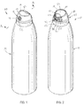
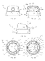
Fig. 1 is an isometric view from the front and above of a hand-held, finger-operable dispensing package that incorporates a dispensing system that includes a valve assembly (not visible inFig. 1 ) and a cooperating finger-operable locking actuator installed on a container of pressurized product, with the actuator shown in a locked and un-actuated condition; -
Fig. 2 is an isometric view from the rear and above of the dispensing package and actuator ofFig. 1 , again with the actuator shown in the locked and un-actuated condition; -
Fig. 3 is a view similar toFig. 1 but showing the actuator in an unlocked and un-actuated condition; -
Fig. 4 is a view similar toFig. 2 but showing the actuator in an unlocked and un-actuated condition; -
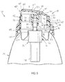
Fig. 5 is an enlarged, fragmentary, cross-sectional view taken along line A-A inFig. 1 , with a diagrammatic representation of a valve body of the dispensing system, and showing the dispensing system in the locked condition preventing actuation; -
Fig. 6 is an enlarged, fragmentary, cross-sectional view taken along line A-A inFig. 3 , again with the diagrammatic representation of the valve body, and showing the dispensing system in the unlocked condition permitting actuation; -
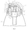
Fig. 7 is a view similar toFig. 6 , but showing the actuator in an unlocked and actuated condition and the valve body in an actuated condition; -
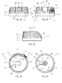
Fig. 8 is an enlarged, exploded isometric view from the front and above showing a shell component and a rotatable member component of the actuator ofFig. 1 ; -
Fig. 9 is an enlarged, exploded isometric view from the rear and below showing the actuator components ofFig. 5 ; -
Fig. 10 is a further enlarged, partial cross-sectional view showing a snap fit connection between the shell and the rotatable member components, with the container not shown for ease of illustration; -
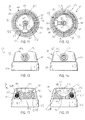
Fig. 11 is a bottom view of the actuator ofFigs. 1-10 , with the actuator shown in the locked and un-actuated condition; -
Fig. 12 is a view similar toFig. 11 , but showing the actuator in the unlocked and un-actuated condition; -
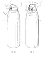
Fig. 13 is a front elevational view of the actuator ofFigs. 1-10 , with the actuator shown in the locked and un-actuated condition; -
Fig. 14 is a view similar toFig. 13 , but showing the actuator in the unlocked and un-actuated condition; -
Fig. 15 is a rear elevational view of the actuator ofFigs. 1-10 , with the actuator shown in the locked and un-actuated condition; -
Fig. 16 is a view similar toFig. 15 , but showing the actuator in the unlocked and un-actuated condition; -
Fig. 17 is a left-side elevational view of the actuator ofFigs. 1-10 (relative to the rear), with the actuator shown in the locked and un-actuated condition; -
Fig. 18 is a view similar toFig. 17 , but showing the actuator in the unlocked and un-actuated condition; -
Fig. 19 is a top plan view of the actuator ofFigs. 1-10 , with the actuator shown in the locked and un-actuated condition; -
Fig. 20 is a view similar toFig. 19 , but showing the actuator in the unlocked and un-actuated condition; -
Fig. 21 is a front elevational view of the shell component of the actuator ofFigs. 1-20 ; -
Fig. 22 is a rear elevational view of the shell component; -
Fig. 23 is a left-side elevational view of the shell component (relative to the rear); -
Fig. 24 is a top plan view of the shell component; -
Fig. 25 is a bottom view of the shell component; -
Fig. 26 is a front elevational view of the rotatable member component of the actuator ofFigs. 1-20 ; -
Fig. 27 is a rear elevational view of the rotatable member component; -
Fig. 28 is a left-side elevational view of the rotatable member component (relative to the rear); -
Fig. 29 is a top, plan view of the rotatable member component; -
Fig. 30 is a bottom view of the rotatable member component; -
Fig. 31 is an isometric view from the front and above of a hand-held, finger-operable dispensing package similar toFig. 1 but showing a second embodiment of a cooperating finger-operable locking actuator installed on a container of pressurized product, with the actuator shown in a locked and un-actuated condition; -
Fig. 32 is an isometric view from the rear and above of the dispensing package and actuator ofFig. 31 , again with the actuator shown in the locked and un-actuated condition; -
Fig. 33 is a view similar toFig. 31 but showing the actuator in an unlocked and un-actuated condition; -
Fig. 34 is a view similar toFig. 32 but showing the actuator in an unlocked and un-actuated condition; -
Fig. 35 is an enlarged, exploded isometric view from the front and above showing a shell component and a rotatable member component of the actuator ofFigs. 31-34 ; -
Fig. 36 is an enlarged, exploded isometric view from the rear and below showing the actuator components ofFig. 35 ; -
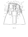
Fig. 37 is an enlarged, fragmentary, cross-sectional view taken along line A-A inFig. 31 , with a diagrammatic representation of a valve body of the dispensing system, and showing the dispensing system in the locked condition preventing actuation; -
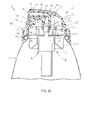
Fig. 38 is an enlarged, fragmentary, cross-sectional view taken along line A-A inFig. 32 , again with the diagrammatic representation of the valve body, and showing the dispensing system in the unlocked condition permitting actuation; -
Fig. 39 is a further enlarged, partial cross-sectional view showing a snap fit connection between the shell and the rotatable member components, with the container not shown for ease of illustration; -
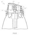
Fig. 40 is an enlarged cross-sectional view taken along line B-B inFig. 31 showing the actuator in the locked and un-actuated condition; -
Fig. 41 is a view similar toFig. 40 , but taken along line B-B inFig. 33 to show the actuator in the unlocked and un-actuated condition; -
Fig. 42 is a front elevational view of the actuator ofFigs. 31-41 , with the actuator shown in the locked and un-actuated condition; -
Fig. 43 is a rear elevational view of the actuator ofFigs. 31-41 , with the actuator shown in the locked and un-actuated condition; -
Fig. 44 is a left-side elevational view of the actuator ofFigs. 31-41 (relative to the rear), with the actuator shown in the locked and un-actuated condition; -
Fig. 45 is a top plan view of the actuator ofFigs. 31-41 , with the actuator shown in the locked and un-actuated condition; -
Fig. 46 is a bottom view of the actuator ofFigs. 31-41 , with the actuator shown in the locked and un-actuated condition; -
Fig. 47 is a front elevational view of the rotatable member component of the actuator ofFigs. 31-46 ; -
Fig. 48 is a rear elevational view of the rotatable member component ofFig. 47 ; -
Fig. 49 is a left-side elevational view of the rotatable member component ofFig. 47 (relative to the rear); -
Fig. 50 is a top, plan view of the rotatable member component ofFig. 47 ; -
Fig. 51 is a bottom view of the rotatable member component ofFig. 47 ; and -
Fig. 52 is a bottom view of the exterior housing component of the actuator ofFigs. 31-46 . - While this invention is susceptible of embodiment in many different forms, this specification and the accompanying drawings disclose only some specific forms as examples of the invention. The invention is not intended to be limited to the embodiments so described, however. The scope of the invention is pointed out in the appended claims.
- For ease of description, the components of this invention are described, along with the container and valve, in a typical (upright) position, and terms such as upper, lower, horizontal, etc., are used with reference to this position. It will be understood, however, that the components embodying this invention may be manufactured, stored, transported, used, and sold in an orientation other than the position described.
- Figures illustrating the components of this invention and the container show some conventional mechanical elements that are known and that will be recognized by one skilled in the art. The detailed descriptions of such elements are not necessary to an understanding of the invention, and accordingly, are herein presented only to the degree necessary to facilitate an understanding of the novel features of the present invention.
- As will be further described in detail, the present invention is directed to a lockable, finger-operable actuator used in dispensing fluent material or product from a container of a dispensing package, such as for dispensing pressurized fluent product from the associated container.
-
Figs. 1-6 illustrate a hand-helddispensing package 10 including apressurized container 14 containing a fluent product, a dispensing valve 16 (shown diagrammatically inFigs. 5 and6 ) in the form of an aerosol dispensing valve or a bag-on-valve dispensing valve (bag not shown), and a finger-operable, lockingactuator 18. As will be described more fully below, a user can selectively manipulate theactuator 18 between a locked position (Figs. 1, 2 , and5 ) wherein thevalve 16 cannot be actuated and an unlocked position (Figs. 3, 4 , and6 ) wherein thevalve 16 can be actuated (Fig. 7 ) to dispense the fluent product. In the preferred embodiments illustrated herein, this manipulation can be performed with a single finger, such as with a thumb, of the user while the user is holding thecontainer 14 in the same hand as the single finger used in the manipulation. - It should be understood that the
container 14 andvalve 16 can be of any conventional, known construction, and accordingly will only be briefly described herein. Thecontainer 14 is typically a metal can having an upper edge rolled into a mountingbead 22 surrounding acontainer opening 24, as best seen inFigs. 5 and6 . Thecontainer 14 is adapted to hold the fluent product (e.g., a liquid (not shown)) and pressurized gas (not shown) below the dispensingvalve 16. - The dispensing
valve 16 may be of any suitable conventional or special type. With reference toFigs. 5 and6 , the dispensingvalve 16 will typically include abody 26 containing the working components of thevalve 16, with thebottom end 28 of thebody 26 being attached to a conventional dip tube (not shown) that directs the fluent product from thecontainer 14 and into thebody 26 to be dispensed from thecontainer 14. The upper end of thebody 26 is typically avalve stem 30 that projects above the top of thecontainer 14 to be actuated from a closed position (Figs. 5 and6 ) wherein fluent product is not dispensed through thevalve 16 and to an open position (Fig. 7 ) wherein the fluent product is dispensed through thevalve 16 via thevalve stem 30. Typically, thevalve stem 30 is biased to the closed position, such as by a spring (not visible) contained in thevalve body 26, so that thevalve 16 is normally closed unless forced to the open position by theactuator 18 as it is actuated by a user. After the dispensingvalve 16 is actuated to dispense product as atomized spray or foam, the user terminates the actuation operation so that thevalve stem 30 is returned by the spring (not visible) to the closed position condition (Figs. 5 and6 ) wherein thevalve 16 is closed. - The dispensing
valve 16 is mounted to thecontainer 14 by any suitable means. As shown inFigs. 5 and6 , one such suitable means is a conventionalvalve mounting cup 32 which has a mountingflange 34 with an outerperipheral portion 36 that can be crimped about thecontainer mounting bead 22 to provide a secure and sealed attachment of the mountingcup 32 to thecontainer 14 at thecontainer opening 24. - The mounting
cup 32 includes an annularinner wall 38 which defines an opening through which a portion of thevalve body 26 projects, with a portion of the annularinner wall 38 crimped to the exterior of thevalve body 26 to provide a secure and sealed attachment of thevalve body 26 to the mountingcup 32. -
U.S. Published Application Number 2008/0210710 A1 , andU.S. Patent Numbers 7,249,692 and7,861,894 each show and describe in further detail other suitable forms ofvalves 16 that can be employed in connection with the present invention. - It will be appreciated that the particular type of the
dispenser valve 16 may be of any suitable design for dispensing a product from the container 14 (with or without a dip tube) out through thevalve stem 30. The detailed design and construction of the dispensingvalve 16 per se forms no part of the present invention. It should further be understood that while the preferred embodiments of the lockingactuator 18 are shown herein in connection with an dispensingvalve 16, in some applications it may be desirable to utilize anactuator 18 according to the invention with other types of dispensing devices. - As best seen in
Figs. 5-9 , the lockingactuator 18 includes anexterior housing 40 and arotatable member 42. Theexterior housing 40 includes a downwardly extending skirt orbase 44 to secure theactuator 18 to thecontainer 14. Theexterior housing 40 also includes ashell 46 defining an interior chamber 48 (Figs. 5-7 and9 ), acircumferentially extending window 50 extending radially between theinterior chamber 48 and an exterior of theshell 46 and circumferentially betweenside edges Fig. 22 ) of theshell 46, and anactuator button 52 movable between an un-actuated position (shown inFigs. 5 ,6 ,8, 9 ) and an actuated position (shown inFig. 7 ). Therotatable member 42 is located in theinterior chamber 48 to rotate relative to the exterior housing between a locked position (Figs. 1, 2 ,5 ) wherein movement of theactuator button 52 from the un-actuated position to the actuated position is prevented to an unlocked position (Figs. 3, 4 ,6 ,7 ) wherein movement of theactuator button 52 from the un-actuated position (Figs. 3, 4 ,6 ) to the actuated position (Fig. 7 ) is allowed to actuate thevalve 16. To enable the above rotation of therotatable member 42 by a user, therotatable member 42 has anengagable surface 54 located in thecircumferentially extending window 50 to be engaged by a user for movement between a first position (best seen inFigs. 2 ,15 ,19 ) corresponding to the locked position and a second position (best seen inFigs. 4 ,16 ,20 ) corresponding to the unlocked position. In the illustrated embodiments, theengagable surface 54 is especially adapted for engagement by the finger of a user, such as a thumb or index finger, and has a concave shape with a textured pattern formed on thesurface 54 as a series of raised, concentric,circular beads 55. It will be appreciated that there are many possible configurations for theengagable surface 54 and that in some applications a concave shape and/or a textured pattern may not be desired. Preferably, therotatable member 42 is mounted to rotate about a vertical axis centered on thevalve body 26 andstem 30. - As best seen in
Figs. 6 and7 , therotatable member 42 preferably includes astem pocket 56 to receive thevalve stem 30, and aflow path 58 to direct fluent product from thevalve stem 30 and thestem pocket 56 to an exterior of theactuator 18. In this regard, theflow path 58 extends laterally to anexit port 60, which in the illustrated embodiment has an annular configuration into which can be press-fit a conventional mechanical breakup unit (MBU) orspray insert 62 having an exit orifice 64 (shown inFigs. 6 and7 , but not shown inFig. 8 ). Therotatable member 42 also preferably includes a cantileveredarm 66 with thestem pocket 56 and flowpath 58 defined therein, as best seen inFigs. 6-8 . Thearm 66 is movable between a neutral position (Figs. 5 ,6 ,8 and 9 ) wherein thestem pocket 56 is located so as not to actuate thevalve 16 and an actuating position (Fig. 7 ) wherein thestem pocket 56 is located to actuate thevalve 16 to dispense a fluent product. Thearm 66 is biased to the neutral position, which in the illustrated embodiment is the as-molded condition or as-formed condition of therotatable member 42 including thearm 66. - As best seen in
Figs. 6 and7 , theactuator button 52 overlies at least part of thearm 66 and engages thearm 66 to move thearm 66 from the neutral position (Fig. 6 ) to the actuating position (Fig. 7 ) when therotatable member 42 is in the unlocked position and theactuating button 52 is moved from the un-actuated position (Fig. 6 ) to the actuated position (Fig. 7 ) by a finger, such as a thumb or index finger, of a user. In this regard, as best seen inFigs. 6 ,7 , and25 , the underside of theactuator button 52 preferably includes anelongate bead 68 that engages thearm 66 for the above-described movement. Further in this regard, thearm 66 preferably includes a relief or notch 70 (best seen inFig. 29 ) that underlies thebead 68 with therotatable member 42 in the locked position, as shown inFig. 5 , to prevent contact between thebead 68 and thearm 66. As shown in the illustrated embodiment, theactuator button 52 is preferably cantilevered on theshell 46 for movement between the un-actuated and actuated positions, with theactuator button 52 being biased toward the un-actuated position, which in the illustrated embodiment is the as-molded condition or as-formed condition of theexterior housing 40 including theactuator button 52. - As best seen in
Figs. 5-8 , theshell 46 of theexterior housing 40 preferably has a dispensingport 72 formed therein. Theexit port 60 of theflow path 58 is aligned with the dispensingport 72 when therotatable member 42 is in the un-locked position (Figs. 3, 4 ,6 ,7 ), and circumferentially spaced from the dispensingport 72 when therotatable member 42 is in the locked position (Figs. 1, 2 ,5 ). This has the advantage of covering the exit port 60 (andexit orifice 64 if aspray insert 62 is included) when theactuator 18 is in the locked condition, thereby protecting the port 60 (andorifice 64 if included) from debris. - As best seen in
Fig. 5 , therotatable member 42 preferably includes first and second upwardly facing, stop surfaces 74 (only one shown inFig. 5 ) that abut a downwardly facingstop surface 76 of theactuator button 52 to prevent movement of theactuator button 52 from the un-actuated position to the actuated position when the rotatable member is in the locked position. Each of the stop surfaces 74 is preferably provided on a corresponding, radially inwardly extending tab or rib 78 (both shown inFigs. 6 ,9 and29 ) of therotatable member 42. The stop surfaces 74 are located on therotatable member 42 so that they abut thestop surface 76 of theactuator button 52 when therotatable member 42 is in the locked position (Fig. 5 ) and so that they do not abut thestop surface 76 when therotatable member 42 is in the un-locked position (Figs. 6 and7 ). In this regard, the stop surfaces 74 andcorresponding ribs 78 of therotatable member 42 underlie thestop surface 76 of theactuator button 52 when therotatable member 42 is in the locked position (Figs. 5 and11 ) and are circumferentially spaced from and do not underlie thestop surface 76 when the rotatable member is in the unlocked position (Figs. 6 ,7 , and12 ). - As best seen in
Figs. 9, 10 ,11, 12 , and25 , theexterior housing 40 preferably includes a plurality of circumferentially spaced, radially inwardly extending tabs orribs 80, with eachrib 80 having radially inwardly pointedtip 82 that, as shown inFig. 9 , provides a snap fit engagement with a downwardly facing,annular surface 84 of therotatable member 42. This arrangement allows for therotatable member 42 to be retained in theinterior chamber 48 while also being rotatable relative to theexterior housing 40. - As best seen in
Figs. 26-30 , therotatable member 42 includes anannular wall 86 having lowercylindrical portion 88 and anupper portion 90 that, in the illustrated embodiment, is gently curved radially inwardly as thewall 86 extends upwardly from thecylindrical portion 88. The engageable surface 54 (Figs. 27 and 29 ) is provided on aprojection 91 extending radially outwardly from an outer surface of theupper portion 90. In the illustrated embodiment, circumferentially spaced,vertical serrations 92 are provided on the outer surface of theupper portion 90. As best seen inFig. 2 , in the illustrated embodiment, a directional indicium in the form of a relieved, swoopingarrow 94 is also provided on the outer surface of theupper portion 90 to provide instructional information to a user for movement of therotatable member 42 from the locked position to the unlocked position. As best seen inFigs. 26, 27, and 29 , in the illustrated embodiment, a pair ofvertical slots 96 are provided in theupper portion 90 on either side ofcantilevered arm 66 to reduce the force required to move the cantileveredarm 66 from the neutral position (Figs. 5 ,6 ) to the actuating position (Fig. 7 ). As best seen inFig. 4 , acurved relief 98 is also provided in theupper portion 90 to provide better user access for movement of theactuator button 52 from the un-actuated position to the actuated position. As best seen inFig. 2 , anothercurved relief 100, smaller than thecurved relief 98, is provided in theupper portion 90 to generally conform the shape of theupper portion 90 to the adjacent portion of theactuator button 52 when the rotatable member is in the locked position. - As best seen in
Figs. 4-7 and22-24 , theactuator button 52 includes anupper wall 110 that is generally circular when viewed from above and a vertical extendingwall 112 that extends downwardly from theupper wall 110 into theinterior chamber 48 and terminates at thestop surface 76. In the illustrated embodiment, thewall 112 has a curved shape extending between circumferentially spaced, generally vertical side edges 114, as best seen inFig. 22 . As best seen inFigs 24 and 25 , the majority of theactuator button 52 is spaced from the remainder of theshell 46 by agap 116, with a forward portion of theactuator button 52 being joined to theshell 46 by an arcuate shapedbridge 118 that extends radially across thegap 116 and circumferentially between spaced side edges 120. Thegap 116 widens to aslot 122 that is partially defined by thewindow 50, partially defined by thewall 112, and partially defined by anedge surface 124 of a radially inwardly extendinghorizontal lip 126 of theexterior housing 40. Preferably, theedge surface 124 has a shape that generally conforms to the outermost peripheral shape of theengagable surface 54 and theupper portion 90 of thewall 86 on therotatable member 42. However, depending upon the resiliency of theexterior housing 40 adjacent theslot 122, in some embodiments it may not be necessary to conform the shape of theedge surface 124 to the outermost peripheral shape of theengageable surface 54. The shape of theslot 122 allows theupper portion 90 of thewall 86, including theengageable surface 54, to be inserted between thewall 112 of theactuator button 52 and theedge surface 124 of thelip 126 during assembly of therotatable member 42 into theinterior chamber 48 so that theengageable surface 54 and a circumferential length of theupper portion 90 of thewall 86 are located in thecircumferentially extending window 50 of theshell 46, as best seen inFigs. 5-7 and15-20 . - As best seen in
Figs. 5-7 and9 , thebase 44 of theexterior housing 40 includes an annularsnap locking feature 130 that secures thebase 44 and the rest of theactuator 18 to thecontainer 14 andvalve 16 combination so as to prevent, or at least inhibit, (1) removal of the actuator 18 from thecontainer 14 andvalve 16 combination, and (2) rotation of theexterior housing 40 relative to thecontainer 14 andvalve 16 combination during normal use, handling, storage, and shipping.Figs. 10 and39 show thesnap locking feature 130 in connection with acup 32 having its outerperipheral portion 36 shown in an alternate configuration after attachment to a container 14 (container 14 not shown inFigs. 10 and39 ). It will be appreciated that there are many suitable constructions for securing the base 44 to thecontainer 14 andvalve 16 combination, and that any such construction may be used for theactuator 18. - In the illustrated embodiment of the
actuator 18, a user will hear a pair of sequenced, audible snapping or clicking sounds as an indication that the unlocked (or locked) position has been reached. A tactile sensation of a pair of sequenced increases and decreases in resistance to the rotation of therotatable member 42 is also sensed by the user. The pair of sequenced audible clicks or snaps, along with the pair of resistance changes, are produced by a cantilevered, resilient tang 131 (best seen inFig. 5 ) extending downwardly from thewall 112 of theactuator button 52. The tworibs 78 on therotatable member 42 contact thetang 131 in sequence as therotatable member 42 is rotated between the locked and unlocked positions and the resulting deflections of thetang 131 produce the audible clicks or snaps and the tactile sensation. -
Figs. 31-51 illustrate another embodiment or modification of theactuator 18, with like reference numbers indicating like features or components and with 18', 40', and 42' indicating the modified actuator 18', exterior housing 40', and rotatable member 42' ofFigs. 31-51 rather than theactuator 18,exterior housing 40, androtatable member 42 ofFigs. 1-30 , respectively. As best seen inFigs. 32 ,34 ,43-45 , and48-50 , the actuator 18' differs cosmetically from theactuator 18 in that thevertical serrations 92 have been removed from theupper portion 90 of thewall 86 of the rotatable member 42', and thecircular beads 55 on theengagable surface 54 have been replaced with a series of vertically extendingbeads 132. - As best seen in
Figs. 36-41 , the actuator 18' differs functionally from theactuator 18 ofFigs. 1-30 in that thelower portion 88 of thewall 86 of the rotatable member 42' has been extended downward and provided with a anannular shoulder 134 having a downwardly facing,annular surface 136 than abuts an upwardly facing,annular surface 138 of thecontainer 14 andvalve 16 combination. This structure allows for the rotatable member 42' to rotate relative to the exterior housing 40' while providing an additional load path from theactuator 18 to thecontainer 14 andvalve 16 combination by transmitting loads through the rotatable member 42' directly to thecontainer 14 andvalve 16 combination rather than from therotatable member 42 through theexterior housing 40 and then to thecontainer 14 andvalve 16 combination as in theactuator 18 ofFigs. 1-30 . This feature provides a robust structure for the actuator 18'. - As best seen in
Figs. 36 and39 , the snap fit connection between the exterior housing 40' and the rotatable member 42' of the actuator 18' also differs from the snap fit connection provided by the radially inwardly pointedtips 82 and downwardly facing,annular surface 84 of theexterior housing 40 androtatable member 42, respectively, in theactuator 18 ofFigs. 1-30 . In this regard each of theribs 80 of the exterior housing 40' is provided with a curved,concave relief 140 that provides a snap fit engagement with a curved, convex,annular bead 142 on thelower portion 88 of thewall 86 of the rotatable member 42'. As seen inFig. 52 , rather than the sevenribs 80 of theexterior housing 40 of the embodiment ofFigs. 1-30 , the exterior housing 40' is provided with sixribs 80 with circumferential locations that differ from the circumferential locations of theribs 80 of thehousing 40 offigs. 1-30 . This snap fit connection accommodates the previously described engagement between theannular shoulder 134 andsurface 136 of the rotatable member 42' while allowing the rotatable member 42' to rotate relative to the exterior housing 40'. It should be noted that this modification to theribs 80 is the only difference between the exterior housing 40' ofFigs. 31-51 and the exterior housing 40' ofFigs. 1-30 . - The interaction between the stop surfaces 74 and 76 is further illustrated in
Figs. 40 and41 , which are section views taken along a line B-B (Figs. 31 ,33 ,46 ) that sections one of theribs 78 with the rotatable member 42' in the locked position.Fig. 40 shows how the stop surfaces 74 and 76 engage each other when theribs 78 underlying thestop surface 76 with the rotatable member 40' in the locked position.Fig. 41 shows how the stop surfaces 74 and 76 do not engage each other when theribs 78 do not underlie thestop surface 76 with the rotatable member 40' in the un-locked position. - Preferably, each of the
components actuators 18, 18', and further that constructions other than a one-piece molded component are possible for each of thecomponents actuator button 52 could be a separate piece that is assembled to the remainder of theexterior housing 40, 40', or that the base 44 could be a separate piece that is assembled to the rest of theexterior housing 40, 40', or that thearm 66 is a separate piece that may or may not rotate with the remainder of therotatable housing 42, 42', or that theengagable surface 54 is part of a separate piece that is assembled to the remainder of therotatable housing 42, 42'. It should be understood that other examples are possible and the foregoing list is not intended to be exhaustive. - It should further be understood that other possible modifications to the
exterior housing 40, 40' androtatable member 42, 42' are contemplated. For example, in some embodiments, it may be desirable to forego any snap fit connection between theexterior housing 40, 40' androtatable member 42, 42' and simply trap therotatable member 42, 42' between theexterior housing 40, 40' and thecontainer 14 andvalve 16 combination. As a further example in this regard, it may be desirable to extend thelower portion 88 of thewall 86 of therotatable member 42, 42' downwardly into the annular channel defined between the mountingflange 34 and theinner wall 38 of thevalve mounting cup 32, with a snap fit connection provided between thecup 32 and thelower portion 88 of therotatable member 40, 40'. - In operation, a user can grasp the dispensing
package 10 in their hand and using a single finger, or more than a single finger if desired, to engage theengageable surface 54 and rotate therotatable member 42, 42' in a counterclockwise direction from the locked position to the unlocked position. The user may then use the same finger or fingers, or a different finger or fingers, to actuate theactuator button 52 in the downward direction, which in turn deflects thearm 66 in the downward direction to initiate a dispensing of the fluent product from thevalve 16. After the desired amount of fluent product is dispensed, the user can release theactuator button 52 which returns to its un-actuated position allowing thearm 66 to return to its neutral position to terminate the dispensing of the fluent product from thevalve 16. The user can then engage theengageable surface 54 and rotate therotatable member 42, 42' in a clockwise direction from the un-locked position to the locked position. It should be appreciated that theactuator 18, 18' could be easily modified so that therotatable member 42, 42' is rotated in a clockwise direction from the locked position to the unlocked position, rather than counterclockwise as in the illustrated embodiments.
Claims (15)
- An actuator (18, 18') for actuating a valve (16) on a container (14) for dispensing a fluent product, the actuator (18, 18) comprising:an exterior housing (40, 40') havinga base (44) to secure the actuator (18, 18') to the container, anda shell (46) definingan interior chamber (48) anda circumferentially extending window (50) extending between the interior chamber (48) and an exterior of the shell (46), characterized in that the shell (46) further definesan actuator button (52) movable between an un-actuatedposition and an actuated position; anda rotatable member (42, 42') located in the interior chamber (48) to rotate relative to the exterior housing (40, 40') betweenthe rotatable member (42, 42') having an engageable surface (54) located in the circumferentially extending window (50) to be engaged by a user for movement of the engageable surface (54) within said window (50) between a first position corresponding to the locked position and a second position corresponding to the unlocked position.a locked position wherein movement of the actuator button (52) from the un-actuated position to the actuated position is prevented andan unlocked position wherein movement of the actuator button (52) from the un-actuated position to the actuated position is allowed to actuate the valve,
- The actuator (18, 18') of claim 1 wherein the rotatable member (42, 42') includes:a stem pocket (56) to receive an outwardly projecting, movable, fluent product-dispensing stem (30) of the valve (16); anda flow path (58) to direct fluent product from the stem pocket (56) to an exterior of the actuator (18, 18').
- The actuator (18, 18') of claim 2 wherein the shell (46) has a dispensing port (72) and the flow path (58) has an exit port (60) that is
aligned with the dispensing port (72) when the rotatable member (42, 42') is in the unlocked position and
circumferentially spaced from the dispensing port (72) when the rotatable member (42, 42') is in the locked position. - The actuator (18, 18') of claim 2 wherein the rotatable member (42, 42') further includes a cantilevered arm (66) with the stem pocket (56) and the flow path (58) defined therein, the arm (66) movable between
a neutral position wherein the stem pocket (56) is located so as not to actuate the valve (16) and
an actuating position wherein the stem pocket (56) is located to actuate the valve (16) to dispense a fluent product. - The actuator (18, 18') of claim 4 wherein the arm (66) is biased toward the neutral position.
- The actuator (18, 18') of claim 4 wherein the actuator button (52) overlies at least part of the cantilevered arm (66) and engages the arm (66) to move the arm (66) from the neutral position to the actuating position when the rotatable member (42, 42') is in the unlocked position and the actuating button (52) moves from the un-actuated position to the actuated position.
- The actuator (18, 18') of claim 1 wherein the actuator button (52) is cantilevered on the shell (46) for movement between the un-actuated and actuated positions.
- The actuator (18, 18') of claim 6 wherein the actuator button (52) is biased toward the un-actuated position.
- The actuator (18, 18') of claim 1 wherein the rotatable member (42, 42') includes a first stop surface (74) that abuts the actuator button (52) to prevent movement of the actuator button (52) from the un-actuated position to the actuated position when the rotatable member (42, 42') is in the locked position.
- The actuator (18, 18') of claim 9 wherein the rotatable member (42, 42') further includes a second stop surface (74) that abuts the actuator button (52) to prevent movement of the actuator button (52) from the un-actuated position to the actuated position when the rotatable member (42, 42') is in the locked position.
- The actuator (18, 18') of claim 9 wherein the actuator button (52) includes a stop surface (76) and wherein
the first stop surface (74) of the rotatable member (42, 42') underlies the stop surface (76) of the actuator button (52) when the rotatable member (42, 42') is in the locked position, and
the first stop surface (74) of the rotatable member (42, 42') does not underlie the stop surface (76) of the actuator button (52) when the rotatable member (42, 42') is in the unlocked position. - The actuator (18, 18') of claim 1 wherein the exterior housing (40, 40') is a one-piece molded component, and wherein the rotatable member (42, 42') is a one-piece molded component.
- The actuator (18, 18') of claim 1 wherein the rotatable member (42, 42') has a snap fit engagement with the exterior housing (40, 40').
- The actuator (18, 18') of claim 1 wherein the rotatable member (42, 42') further comprises a surface (136) located to contact a surface (138) of at least one of said valve (16) and container (14) in at least the locked position of the rotatable member (42, 42').
- The actuator (18, 18') of claim 1 in further combination with said valve (16) and container (14).
Applications Claiming Priority (1)
| Application Number | Priority Date | Filing Date | Title |
|---|---|---|---|
| PCT/US2011/047440 WO2013022452A1 (en) | 2011-08-11 | 2011-08-11 | Lockable dispensing package and actuator |
Publications (3)
| Publication Number | Publication Date |
|---|---|
| EP2707311A1 EP2707311A1 (en) | 2014-03-19 |
| EP2707311A4 EP2707311A4 (en) | 2015-04-08 |
| EP2707311B1 true EP2707311B1 (en) | 2016-12-07 |
Family
ID=47668745
Family Applications (1)
| Application Number | Title | Priority Date | Filing Date |
|---|---|---|---|
| EP11870539.1A Active EP2707311B1 (en) | 2011-08-11 | 2011-08-11 | Lockable dispensing package and actuator |
Country Status (6)
| Country | Link |
|---|---|
| US (1) | US9216852B2 (en) |
| EP (1) | EP2707311B1 (en) |
| CN (1) | CN103717511B (en) |
| AR (1) | AR084746A1 (en) |
| BR (1) | BR112014000900B1 (en) |
| WO (1) | WO2013022452A1 (en) |
Cited By (1)
| Publication number | Priority date | Publication date | Assignee | Title |
|---|---|---|---|---|
| EP3974345A1 (en) | 2020-09-28 | 2022-03-30 | Aptar Radolfzell GmbH | Spray head and dispenser with such a spray head |
Families Citing this family (11)
| Publication number | Priority date | Publication date | Assignee | Title |
|---|---|---|---|---|
| EP3237302A1 (en) * | 2014-12-23 | 2017-11-01 | PZ Cussons (International) Limited | A cap for a container for a post-foaming gel cleansing composition |
| USD821201S1 (en) | 2015-09-21 | 2018-06-26 | S. C. Johnson & Son, Inc. | Container with base |
| USD830827S1 (en) | 2015-09-21 | 2018-10-16 | S. C. Johnson & Son, Inc. | Container with base |
| USD821203S1 (en) | 2015-09-21 | 2018-06-26 | S. C. Johnson & Son, Inc. | Container with cap and base |
| USD821202S1 (en) | 2015-09-21 | 2018-06-26 | S. C. Johnson & Son, Inc. | Container with cap and base |
| USD858288S1 (en) | 2015-09-21 | 2019-09-03 | S. C. Johnson & Son, Inc. | Container with base |
| US10589920B2 (en) | 2016-09-15 | 2020-03-17 | Precision Valve Corporation | System and method for a dispenser to generate different sprays |
| US11130143B2 (en) | 2016-09-15 | 2021-09-28 | Precision Valve Corporation | System and method for dispensing different sprays |
| US10940493B2 (en) | 2018-07-26 | 2021-03-09 | S. C. Johnson & Son, Inc. | Actuator and nozzle insert for dispensing systems |
| IT202000023515A1 (en) * | 2020-10-06 | 2022-04-06 | Coster Tecnologie Speciali Spa | FLUID SUBSTANCE DELIVERY DEVICE |
| WO2024039632A1 (en) * | 2022-08-15 | 2024-02-22 | Aptargroup Inc. | Aerosol actuator |
Family Cites Families (33)
| Publication number | Priority date | Publication date | Assignee | Title |
|---|---|---|---|---|
| US3426948A (en) | 1967-03-01 | 1969-02-11 | Pittsburgh Railways Co | Foam actuator |
| US3601290A (en) | 1969-07-11 | 1971-08-24 | Gillette Co | Aerosol dispenser actuator |
| US3933283A (en) | 1972-07-24 | 1976-01-20 | Elmer Hoagland | Actuator nozzle assembly for aerosol containers |
| US3848778A (en) | 1972-08-14 | 1974-11-19 | P Meshberg | Childproof actuator assembly |
| US3860149A (en) | 1972-12-26 | 1975-01-14 | Scovill Manufacturing Co | Childproof actuator |
| US3937368A (en) * | 1974-03-10 | 1976-02-10 | Elmer Hoagland | Aerosol actuator nozzle |
| US4354621A (en) | 1980-07-23 | 1982-10-19 | Seaquist Valve Co., Div. Of Pittway Corp. | Child resistant assembly for aerosol dispensers |
| US4418842A (en) | 1981-03-31 | 1983-12-06 | Precision Valve Corporation | Child resistant closure |
| GB8306856D0 (en) | 1983-03-12 | 1983-04-20 | Metal Box Plc | Aerosol actuator |
| CA2020223C (en) | 1989-07-19 | 1996-02-27 | Shinya Kobayashi | Aerosol container cap |
| FR2695379B1 (en) | 1992-09-09 | 1994-11-10 | Aerosol Inventions Dev | Lockable valve dispenser for aerosol valve. |
| US5388730A (en) | 1993-11-10 | 1995-02-14 | Enviro Pac International L.L.C. | Lockable actuator for a dispensing canister |
| GB9727366D0 (en) | 1997-12-24 | 1998-02-25 | Unilever Plc | Sprayhead |
| FR2789981B1 (en) | 1999-02-19 | 2001-05-04 | Oreal | LOCKABLE DISTRIBUTION HEAD AND DISTRIBUTOR THUS EQUIPPED |
| GB0003343D0 (en) * | 2000-02-14 | 2000-04-05 | Unilever Plc | Actuator mechanism |
| US6971552B2 (en) * | 2001-08-21 | 2005-12-06 | Dispensing Patents International, Llc | Aerosol dispenser |
| US6695171B2 (en) | 2002-02-12 | 2004-02-24 | Seaquistperfect Dispensing Foreign, Inc. | Pump dispenser |
| US7070069B2 (en) * | 2002-03-07 | 2006-07-04 | Connetics Corporation | Aerosol system having lockable cap |
| US6758373B2 (en) * | 2002-05-13 | 2004-07-06 | Precision Valve Corporation | Aerosol valve actuator |
| EP1537027B1 (en) | 2002-07-22 | 2012-06-27 | Seaquist Perfect Dispensing Foreign, Inc. | Locking aerosol dispenser |
| US7104427B2 (en) * | 2003-01-21 | 2006-09-12 | Precision Valve Corporation | Gapless aerosol valve actuator |
| CN1756715B (en) * | 2003-03-03 | 2012-05-30 | 西奎斯特完美分配器外国公司 | Aerosol actuator |
| US8100298B2 (en) | 2003-03-03 | 2012-01-24 | Aptargroup, Inc. | Aerosol actuator |
| CN101218166B (en) * | 2004-11-29 | 2011-08-17 | 西奎斯特完美分配器外国公司 | Dispenser with lock |
| US20060201970A1 (en) * | 2005-03-11 | 2006-09-14 | Jasek Sidney J | Safety nozzle for aerosol can |
| US7757905B2 (en) * | 2005-08-18 | 2010-07-20 | Summit Packaging Systems, Inc. | Spray actuator |
| US7922041B2 (en) * | 2005-12-29 | 2011-04-12 | The Procter & Gamble Company | Spray dispensers |
| US7530476B2 (en) * | 2006-04-10 | 2009-05-12 | Precision Valve Corporation | Locking aerosol dispenser |
| US7699190B2 (en) * | 2007-01-04 | 2010-04-20 | Precision Valve Corporation | Locking aerosol dispenser |
| DE102007049614B4 (en) * | 2007-03-15 | 2015-03-05 | Aptar Dortmund Gmbh | dispenser |
| US7861894B2 (en) * | 2007-08-22 | 2011-01-04 | Seaquistperfect Dispensing L.L.C. | Lockable dispenser |
| BRPI0920849A2 (en) * | 2008-10-06 | 2015-12-22 | Valspar Sourcing Inc | actuator apparatus for a sprayer container, and method for manufacturing a cover for an actuator apparatus |
| US8540121B2 (en) * | 2009-07-07 | 2013-09-24 | Aptargroup, Inc. | Dispensing actuator with flip-open lid |
-
2011
- 2011-08-11 CN CN201180072814.0A patent/CN103717511B/en active Active
- 2011-08-11 US US14/123,293 patent/US9216852B2/en active Active
- 2011-08-11 EP EP11870539.1A patent/EP2707311B1/en active Active
- 2011-08-11 WO PCT/US2011/047440 patent/WO2013022452A1/en active Application Filing
- 2011-08-11 BR BR112014000900-7A patent/BR112014000900B1/en active IP Right Grant
- 2011-12-29 AR ARP110105023A patent/AR084746A1/en active IP Right Grant
Non-Patent Citations (1)
| Title |
|---|
| None * |
Cited By (1)
| Publication number | Priority date | Publication date | Assignee | Title |
|---|---|---|---|---|
| EP3974345A1 (en) | 2020-09-28 | 2022-03-30 | Aptar Radolfzell GmbH | Spray head and dispenser with such a spray head |
Also Published As
| Publication number | Publication date |
|---|---|
| BR112014000900B1 (en) | 2020-06-02 |
| EP2707311A4 (en) | 2015-04-08 |
| CN103717511A (en) | 2014-04-09 |
| AR084746A1 (en) | 2013-06-05 |
| BR112014000900A2 (en) | 2017-02-21 |
| US9216852B2 (en) | 2015-12-22 |
| CN103717511B (en) | 2016-02-17 |
| US20140124539A1 (en) | 2014-05-08 |
| WO2013022452A1 (en) | 2013-02-14 |
| EP2707311A1 (en) | 2014-03-19 |
Similar Documents
| Publication | Publication Date | Title |
|---|---|---|
| EP2707311B1 (en) | Lockable dispensing package and actuator | |
| EP2181062B1 (en) | Lockable dispenser | |
| US3848778A (en) | Childproof actuator assembly | |
| EP2004538B1 (en) | Locking aerosol dispenser | |
| EP1219547B1 (en) | Sprayhead | |
| EP2607266B1 (en) | Sprayhead for a spray device | |
| EP2451725B1 (en) | Dispensing actuator with flip-open lid | |
| EP1915299B1 (en) | Spray actuator | |
| EP0952892B1 (en) | Combined lock and anti-clog feature for spray package | |
| US6302302B1 (en) | Lockable dispensing head and dispenser equipped therewith | |
| US7611032B2 (en) | Lockable dispensing head | |
| US8622256B2 (en) | Actuator for spray container with restraint structure | |
| US8201710B2 (en) | Attachment mechanism for a dispenser | |
| EP2143661A2 (en) | Aerosol actuator | |
| HU226741B1 (en) | Actuator mechanism for valve | |
| US4171758A (en) | Child-safe actuator for pressurized container | |
| EP1726537B1 (en) | Tamper-indicating spray cap |
Legal Events
| Date | Code | Title | Description |
|---|---|---|---|
| PUAI | Public reference made under article 153(3) epc to a published international application that has entered the european phase |
Free format text: ORIGINAL CODE: 0009012 |
|
| 17P | Request for examination filed |
Effective date: 20131209 |
|
| AK | Designated contracting states |
Kind code of ref document: A1 Designated state(s): AL AT BE BG CH CY CZ DE DK EE ES FI FR GB GR HR HU IE IS IT LI LT LU LV MC MK MT NL NO PL PT RO RS SE SI SK SM TR |
|
| DAX | Request for extension of the european patent (deleted) | ||
| RA4 | Supplementary search report drawn up and despatched (corrected) |
Effective date: 20150310 |
|
| RIC1 | Information provided on ipc code assigned before grant |
Ipc: B65D 83/20 20060101ALI20150304BHEP Ipc: B65D 83/22 20060101AFI20150304BHEP |
|
| GRAP | Despatch of communication of intention to grant a patent |
Free format text: ORIGINAL CODE: EPIDOSNIGR1 |
|
| INTG | Intention to grant announced |
Effective date: 20160715 |
|
| GRAS | Grant fee paid |
Free format text: ORIGINAL CODE: EPIDOSNIGR3 |
|
| GRAA | (expected) grant |
Free format text: ORIGINAL CODE: 0009210 |
|
| AK | Designated contracting states |
Kind code of ref document: B1 Designated state(s): AL AT BE BG CH CY CZ DE DK EE ES FI FR GB GR HR HU IE IS IT LI LT LU LV MC MK MT NL NO PL PT RO RS SE SI SK SM TR |
|
| REG | Reference to a national code |
Ref country code: GB Ref legal event code: FG4D |
|
| REG | Reference to a national code |
Ref country code: CH Ref legal event code: EP Ref country code: AT Ref legal event code: REF Ref document number: 851483 Country of ref document: AT Kind code of ref document: T Effective date: 20161215 |
|
| REG | Reference to a national code |
Ref country code: IE Ref legal event code: FG4D |
|
| REG | Reference to a national code |
Ref country code: DE Ref legal event code: R096 Ref document number: 602011033276 Country of ref document: DE |
|
| PG25 | Lapsed in a contracting state [announced via postgrant information from national office to epo] |
Ref country code: LV Free format text: LAPSE BECAUSE OF FAILURE TO SUBMIT A TRANSLATION OF THE DESCRIPTION OR TO PAY THE FEE WITHIN THE PRESCRIBED TIME-LIMIT Effective date: 20161207 |
|
| REG | Reference to a national code |
Ref country code: LT Ref legal event code: MG4D |
|
| REG | Reference to a national code |
Ref country code: NL Ref legal event code: MP Effective date: 20161207 |
|
| PG25 | Lapsed in a contracting state [announced via postgrant information from national office to epo] |
Ref country code: LT Free format text: LAPSE BECAUSE OF FAILURE TO SUBMIT A TRANSLATION OF THE DESCRIPTION OR TO PAY THE FEE WITHIN THE PRESCRIBED TIME-LIMIT Effective date: 20161207 Ref country code: NO Free format text: LAPSE BECAUSE OF FAILURE TO SUBMIT A TRANSLATION OF THE DESCRIPTION OR TO PAY THE FEE WITHIN THE PRESCRIBED TIME-LIMIT Effective date: 20170307 Ref country code: GR Free format text: LAPSE BECAUSE OF FAILURE TO SUBMIT A TRANSLATION OF THE DESCRIPTION OR TO PAY THE FEE WITHIN THE PRESCRIBED TIME-LIMIT Effective date: 20170308 Ref country code: SE Free format text: LAPSE BECAUSE OF FAILURE TO SUBMIT A TRANSLATION OF THE DESCRIPTION OR TO PAY THE FEE WITHIN THE PRESCRIBED TIME-LIMIT Effective date: 20161207 |
|
| REG | Reference to a national code |
Ref country code: AT Ref legal event code: MK05 Ref document number: 851483 Country of ref document: AT Kind code of ref document: T Effective date: 20161207 |
|
| PG25 | Lapsed in a contracting state [announced via postgrant information from national office to epo] |
Ref country code: FI Free format text: LAPSE BECAUSE OF FAILURE TO SUBMIT A TRANSLATION OF THE DESCRIPTION OR TO PAY THE FEE WITHIN THE PRESCRIBED TIME-LIMIT Effective date: 20161207 Ref country code: RS Free format text: LAPSE BECAUSE OF FAILURE TO SUBMIT A TRANSLATION OF THE DESCRIPTION OR TO PAY THE FEE WITHIN THE PRESCRIBED TIME-LIMIT Effective date: 20161207 Ref country code: ES Free format text: LAPSE BECAUSE OF FAILURE TO SUBMIT A TRANSLATION OF THE DESCRIPTION OR TO PAY THE FEE WITHIN THE PRESCRIBED TIME-LIMIT Effective date: 20161207 Ref country code: HR Free format text: LAPSE BECAUSE OF FAILURE TO SUBMIT A TRANSLATION OF THE DESCRIPTION OR TO PAY THE FEE WITHIN THE PRESCRIBED TIME-LIMIT Effective date: 20161207 |
|
| PG25 | Lapsed in a contracting state [announced via postgrant information from national office to epo] |
Ref country code: NL Free format text: LAPSE BECAUSE OF FAILURE TO SUBMIT A TRANSLATION OF THE DESCRIPTION OR TO PAY THE FEE WITHIN THE PRESCRIBED TIME-LIMIT Effective date: 20161207 |
|
| PG25 | Lapsed in a contracting state [announced via postgrant information from national office to epo] |
Ref country code: RO Free format text: LAPSE BECAUSE OF FAILURE TO SUBMIT A TRANSLATION OF THE DESCRIPTION OR TO PAY THE FEE WITHIN THE PRESCRIBED TIME-LIMIT Effective date: 20161207 Ref country code: IS Free format text: LAPSE BECAUSE OF FAILURE TO SUBMIT A TRANSLATION OF THE DESCRIPTION OR TO PAY THE FEE WITHIN THE PRESCRIBED TIME-LIMIT Effective date: 20170407 Ref country code: CZ Free format text: LAPSE BECAUSE OF FAILURE TO SUBMIT A TRANSLATION OF THE DESCRIPTION OR TO PAY THE FEE WITHIN THE PRESCRIBED TIME-LIMIT Effective date: 20161207 Ref country code: EE Free format text: LAPSE BECAUSE OF FAILURE TO SUBMIT A TRANSLATION OF THE DESCRIPTION OR TO PAY THE FEE WITHIN THE PRESCRIBED TIME-LIMIT Effective date: 20161207 Ref country code: SK Free format text: LAPSE BECAUSE OF FAILURE TO SUBMIT A TRANSLATION OF THE DESCRIPTION OR TO PAY THE FEE WITHIN THE PRESCRIBED TIME-LIMIT Effective date: 20161207 |
|
| REG | Reference to a national code |
Ref country code: FR Ref legal event code: PLFP Year of fee payment: 7 |
|
| PG25 | Lapsed in a contracting state [announced via postgrant information from national office to epo] |
Ref country code: SM Free format text: LAPSE BECAUSE OF FAILURE TO SUBMIT A TRANSLATION OF THE DESCRIPTION OR TO PAY THE FEE WITHIN THE PRESCRIBED TIME-LIMIT Effective date: 20161207 Ref country code: PL Free format text: LAPSE BECAUSE OF FAILURE TO SUBMIT A TRANSLATION OF THE DESCRIPTION OR TO PAY THE FEE WITHIN THE PRESCRIBED TIME-LIMIT Effective date: 20161207 Ref country code: BE Free format text: LAPSE BECAUSE OF FAILURE TO SUBMIT A TRANSLATION OF THE DESCRIPTION OR TO PAY THE FEE WITHIN THE PRESCRIBED TIME-LIMIT Effective date: 20161207 Ref country code: PT Free format text: LAPSE BECAUSE OF FAILURE TO SUBMIT A TRANSLATION OF THE DESCRIPTION OR TO PAY THE FEE WITHIN THE PRESCRIBED TIME-LIMIT Effective date: 20170407 Ref country code: BG Free format text: LAPSE BECAUSE OF FAILURE TO SUBMIT A TRANSLATION OF THE DESCRIPTION OR TO PAY THE FEE WITHIN THE PRESCRIBED TIME-LIMIT Effective date: 20170307 Ref country code: AT Free format text: LAPSE BECAUSE OF FAILURE TO SUBMIT A TRANSLATION OF THE DESCRIPTION OR TO PAY THE FEE WITHIN THE PRESCRIBED TIME-LIMIT Effective date: 20161207 |
|
| REG | Reference to a national code |
Ref country code: DE Ref legal event code: R097 Ref document number: 602011033276 Country of ref document: DE |
|
| PLBE | No opposition filed within time limit |
Free format text: ORIGINAL CODE: 0009261 |
|
| STAA | Information on the status of an ep patent application or granted ep patent |
Free format text: STATUS: NO OPPOSITION FILED WITHIN TIME LIMIT |
|
| 26N | No opposition filed |
Effective date: 20170908 |
|
| PG25 | Lapsed in a contracting state [announced via postgrant information from national office to epo] |
Ref country code: DK Free format text: LAPSE BECAUSE OF FAILURE TO SUBMIT A TRANSLATION OF THE DESCRIPTION OR TO PAY THE FEE WITHIN THE PRESCRIBED TIME-LIMIT Effective date: 20161207 Ref country code: SI Free format text: LAPSE BECAUSE OF FAILURE TO SUBMIT A TRANSLATION OF THE DESCRIPTION OR TO PAY THE FEE WITHIN THE PRESCRIBED TIME-LIMIT Effective date: 20161207 |
|
| REG | Reference to a national code |
Ref country code: CH Ref legal event code: PL |
|
| PG25 | Lapsed in a contracting state [announced via postgrant information from national office to epo] |
Ref country code: MC Free format text: LAPSE BECAUSE OF FAILURE TO SUBMIT A TRANSLATION OF THE DESCRIPTION OR TO PAY THE FEE WITHIN THE PRESCRIBED TIME-LIMIT Effective date: 20161207 |
|
| PG25 | Lapsed in a contracting state [announced via postgrant information from national office to epo] |
Ref country code: CH Free format text: LAPSE BECAUSE OF NON-PAYMENT OF DUE FEES Effective date: 20170831 Ref country code: LI Free format text: LAPSE BECAUSE OF NON-PAYMENT OF DUE FEES Effective date: 20170831 |
|
| REG | Reference to a national code |
Ref country code: IE Ref legal event code: MM4A |
|
| PG25 | Lapsed in a contracting state [announced via postgrant information from national office to epo] |
Ref country code: LU Free format text: LAPSE BECAUSE OF NON-PAYMENT OF DUE FEES Effective date: 20170811 |
|
| PG25 | Lapsed in a contracting state [announced via postgrant information from national office to epo] |
Ref country code: IE Free format text: LAPSE BECAUSE OF NON-PAYMENT OF DUE FEES Effective date: 20170811 |
|
| REG | Reference to a national code |
Ref country code: FR Ref legal event code: PLFP Year of fee payment: 8 |
|
| PG25 | Lapsed in a contracting state [announced via postgrant information from national office to epo] |
Ref country code: MT Free format text: LAPSE BECAUSE OF NON-PAYMENT OF DUE FEES Effective date: 20170811 |
|
| PG25 | Lapsed in a contracting state [announced via postgrant information from national office to epo] |
Ref country code: HU Free format text: LAPSE BECAUSE OF FAILURE TO SUBMIT A TRANSLATION OF THE DESCRIPTION OR TO PAY THE FEE WITHIN THE PRESCRIBED TIME-LIMIT; INVALID AB INITIO Effective date: 20110811 |
|
| PG25 | Lapsed in a contracting state [announced via postgrant information from national office to epo] |
Ref country code: CY Free format text: LAPSE BECAUSE OF NON-PAYMENT OF DUE FEES Effective date: 20161207 |
|
| PG25 | Lapsed in a contracting state [announced via postgrant information from national office to epo] |
Ref country code: MK Free format text: LAPSE BECAUSE OF FAILURE TO SUBMIT A TRANSLATION OF THE DESCRIPTION OR TO PAY THE FEE WITHIN THE PRESCRIBED TIME-LIMIT Effective date: 20161207 |
|
| PG25 | Lapsed in a contracting state [announced via postgrant information from national office to epo] |
Ref country code: TR Free format text: LAPSE BECAUSE OF FAILURE TO SUBMIT A TRANSLATION OF THE DESCRIPTION OR TO PAY THE FEE WITHIN THE PRESCRIBED TIME-LIMIT Effective date: 20161207 |
|
| PG25 | Lapsed in a contracting state [announced via postgrant information from national office to epo] |
Ref country code: AL Free format text: LAPSE BECAUSE OF FAILURE TO SUBMIT A TRANSLATION OF THE DESCRIPTION OR TO PAY THE FEE WITHIN THE PRESCRIBED TIME-LIMIT Effective date: 20161207 |
|
| P01 | Opt-out of the competence of the unified patent court (upc) registered |
Effective date: 20230503 |
|
| PGFP | Annual fee paid to national office [announced via postgrant information from national office to epo] |
Ref country code: IT Payment date: 20230921 Year of fee payment: 13 Ref country code: GB Payment date: 20230927 Year of fee payment: 13 |
|
| PGFP | Annual fee paid to national office [announced via postgrant information from national office to epo] |
Ref country code: FR Payment date: 20230925 Year of fee payment: 13 Ref country code: DE Payment date: 20230927 Year of fee payment: 13 |