EP2706933B1 - Facet interference cage - Google Patents
Facet interference cage Download PDFInfo
- Publication number
- EP2706933B1 EP2706933B1 EP12722019.2A EP12722019A EP2706933B1 EP 2706933 B1 EP2706933 B1 EP 2706933B1 EP 12722019 A EP12722019 A EP 12722019A EP 2706933 B1 EP2706933 B1 EP 2706933B1
- Authority
- EP
- European Patent Office
- Prior art keywords
- implant
- bone fixation
- fixation element
- facet joint
- guide
- Prior art date
- Legal status (The legal status is an assumption and is not a legal conclusion. Google has not performed a legal analysis and makes no representation as to the accuracy of the status listed.)
- Active
Links
Images


Classifications
-
- A—HUMAN NECESSITIES
- A61—MEDICAL OR VETERINARY SCIENCE; HYGIENE
- A61B—DIAGNOSIS; SURGERY; IDENTIFICATION
- A61B17/00—Surgical instruments, devices or methods
- A61B17/16—Instruments for performing osteoclasis; Drills or chisels for bones; Trepans
- A61B17/1662—Instruments for performing osteoclasis; Drills or chisels for bones; Trepans for particular parts of the body
- A61B17/1671—Instruments for performing osteoclasis; Drills or chisels for bones; Trepans for particular parts of the body for the spine
-
- A—HUMAN NECESSITIES
- A61—MEDICAL OR VETERINARY SCIENCE; HYGIENE
- A61B—DIAGNOSIS; SURGERY; IDENTIFICATION
- A61B17/00—Surgical instruments, devices or methods
- A61B17/02—Surgical instruments, devices or methods for holding wounds open, e.g. retractors; Tractors
- A61B17/0206—Surgical instruments, devices or methods for holding wounds open, e.g. retractors; Tractors with antagonistic arms as supports for retractor elements
-
- A—HUMAN NECESSITIES
- A61—MEDICAL OR VETERINARY SCIENCE; HYGIENE
- A61B—DIAGNOSIS; SURGERY; IDENTIFICATION
- A61B17/00—Surgical instruments, devices or methods
- A61B17/16—Instruments for performing osteoclasis; Drills or chisels for bones; Trepans
- A61B17/1697—Instruments for performing osteoclasis; Drills or chisels for bones; Trepans specially adapted for wire insertion
-
- A—HUMAN NECESSITIES
- A61—MEDICAL OR VETERINARY SCIENCE; HYGIENE
- A61B—DIAGNOSIS; SURGERY; IDENTIFICATION
- A61B17/00—Surgical instruments, devices or methods
- A61B17/56—Surgical instruments or methods for treatment of bones or joints; Devices specially adapted therefor
- A61B17/58—Surgical instruments or methods for treatment of bones or joints; Devices specially adapted therefor for osteosynthesis, e.g. bone plates, screws or setting implements
- A61B17/68—Internal fixation devices, including fasteners and spinal fixators, even if a part thereof projects from the skin
- A61B17/70—Spinal positioners or stabilisers, e.g. stabilisers comprising fluid filler in an implant
- A61B17/7062—Devices acting on, attached to, or simulating the effect of, vertebral processes, vertebral facets or ribs ; Tools for such devices
- A61B17/7064—Devices acting on, attached to, or simulating the effect of, vertebral facets; Tools therefor
-
- A—HUMAN NECESSITIES
- A61—MEDICAL OR VETERINARY SCIENCE; HYGIENE
- A61F—FILTERS IMPLANTABLE INTO BLOOD VESSELS; PROSTHESES; DEVICES PROVIDING PATENCY TO, OR PREVENTING COLLAPSING OF, TUBULAR STRUCTURES OF THE BODY, e.g. STENTS; ORTHOPAEDIC, NURSING OR CONTRACEPTIVE DEVICES; FOMENTATION; TREATMENT OR PROTECTION OF EYES OR EARS; BANDAGES, DRESSINGS OR ABSORBENT PADS; FIRST-AID KITS
- A61F2/00—Filters implantable into blood vessels; Prostheses, i.e. artificial substitutes or replacements for parts of the body; Appliances for connecting them with the body; Devices providing patency to, or preventing collapsing of, tubular structures of the body, e.g. stents
- A61F2/02—Prostheses implantable into the body
- A61F2/30—Joints
- A61F2/30767—Special external or bone-contacting surface, e.g. coating for improving bone ingrowth
-
- A—HUMAN NECESSITIES
- A61—MEDICAL OR VETERINARY SCIENCE; HYGIENE
- A61F—FILTERS IMPLANTABLE INTO BLOOD VESSELS; PROSTHESES; DEVICES PROVIDING PATENCY TO, OR PREVENTING COLLAPSING OF, TUBULAR STRUCTURES OF THE BODY, e.g. STENTS; ORTHOPAEDIC, NURSING OR CONTRACEPTIVE DEVICES; FOMENTATION; TREATMENT OR PROTECTION OF EYES OR EARS; BANDAGES, DRESSINGS OR ABSORBENT PADS; FIRST-AID KITS
- A61F2/00—Filters implantable into blood vessels; Prostheses, i.e. artificial substitutes or replacements for parts of the body; Appliances for connecting them with the body; Devices providing patency to, or preventing collapsing of, tubular structures of the body, e.g. stents
- A61F2/02—Prostheses implantable into the body
- A61F2/30—Joints
- A61F2/44—Joints for the spine, e.g. vertebrae, spinal discs
- A61F2/4405—Joints for the spine, e.g. vertebrae, spinal discs for apophyseal or facet joints, i.e. between adjacent spinous or transverse processes
-
- A—HUMAN NECESSITIES
- A61—MEDICAL OR VETERINARY SCIENCE; HYGIENE
- A61F—FILTERS IMPLANTABLE INTO BLOOD VESSELS; PROSTHESES; DEVICES PROVIDING PATENCY TO, OR PREVENTING COLLAPSING OF, TUBULAR STRUCTURES OF THE BODY, e.g. STENTS; ORTHOPAEDIC, NURSING OR CONTRACEPTIVE DEVICES; FOMENTATION; TREATMENT OR PROTECTION OF EYES OR EARS; BANDAGES, DRESSINGS OR ABSORBENT PADS; FIRST-AID KITS
- A61F2/00—Filters implantable into blood vessels; Prostheses, i.e. artificial substitutes or replacements for parts of the body; Appliances for connecting them with the body; Devices providing patency to, or preventing collapsing of, tubular structures of the body, e.g. stents
- A61F2/02—Prostheses implantable into the body
- A61F2/30—Joints
- A61F2/44—Joints for the spine, e.g. vertebrae, spinal discs
- A61F2/442—Intervertebral or spinal discs, e.g. resilient
-
- A—HUMAN NECESSITIES
- A61—MEDICAL OR VETERINARY SCIENCE; HYGIENE
- A61F—FILTERS IMPLANTABLE INTO BLOOD VESSELS; PROSTHESES; DEVICES PROVIDING PATENCY TO, OR PREVENTING COLLAPSING OF, TUBULAR STRUCTURES OF THE BODY, e.g. STENTS; ORTHOPAEDIC, NURSING OR CONTRACEPTIVE DEVICES; FOMENTATION; TREATMENT OR PROTECTION OF EYES OR EARS; BANDAGES, DRESSINGS OR ABSORBENT PADS; FIRST-AID KITS
- A61F2/00—Filters implantable into blood vessels; Prostheses, i.e. artificial substitutes or replacements for parts of the body; Appliances for connecting them with the body; Devices providing patency to, or preventing collapsing of, tubular structures of the body, e.g. stents
- A61F2/02—Prostheses implantable into the body
- A61F2/30—Joints
- A61F2/44—Joints for the spine, e.g. vertebrae, spinal discs
- A61F2/4455—Joints for the spine, e.g. vertebrae, spinal discs for the fusion of spinal bodies, e.g. intervertebral fusion of adjacent spinal bodies, e.g. fusion cages
-
- A—HUMAN NECESSITIES
- A61—MEDICAL OR VETERINARY SCIENCE; HYGIENE
- A61F—FILTERS IMPLANTABLE INTO BLOOD VESSELS; PROSTHESES; DEVICES PROVIDING PATENCY TO, OR PREVENTING COLLAPSING OF, TUBULAR STRUCTURES OF THE BODY, e.g. STENTS; ORTHOPAEDIC, NURSING OR CONTRACEPTIVE DEVICES; FOMENTATION; TREATMENT OR PROTECTION OF EYES OR EARS; BANDAGES, DRESSINGS OR ABSORBENT PADS; FIRST-AID KITS
- A61F2/00—Filters implantable into blood vessels; Prostheses, i.e. artificial substitutes or replacements for parts of the body; Appliances for connecting them with the body; Devices providing patency to, or preventing collapsing of, tubular structures of the body, e.g. stents
- A61F2/02—Prostheses implantable into the body
- A61F2/30—Joints
- A61F2/46—Special tools for implanting artificial joints
- A61F2/4603—Special tools for implanting artificial joints for insertion or extraction of endoprosthetic joints or of accessories thereof
- A61F2/4611—Special tools for implanting artificial joints for insertion or extraction of endoprosthetic joints or of accessories thereof of spinal prostheses
-
- A—HUMAN NECESSITIES
- A61—MEDICAL OR VETERINARY SCIENCE; HYGIENE
- A61B—DIAGNOSIS; SURGERY; IDENTIFICATION
- A61B90/00—Instruments, implements or accessories specially adapted for surgery or diagnosis and not covered by any of the groups A61B1/00 - A61B50/00, e.g. for luxation treatment or for protecting wound edges
- A61B90/03—Automatic limiting or abutting means, e.g. for safety
- A61B2090/033—Abutting means, stops, e.g. abutting on tissue or skin
- A61B2090/034—Abutting means, stops, e.g. abutting on tissue or skin abutting on parts of the device itself
-
- A—HUMAN NECESSITIES
- A61—MEDICAL OR VETERINARY SCIENCE; HYGIENE
- A61F—FILTERS IMPLANTABLE INTO BLOOD VESSELS; PROSTHESES; DEVICES PROVIDING PATENCY TO, OR PREVENTING COLLAPSING OF, TUBULAR STRUCTURES OF THE BODY, e.g. STENTS; ORTHOPAEDIC, NURSING OR CONTRACEPTIVE DEVICES; FOMENTATION; TREATMENT OR PROTECTION OF EYES OR EARS; BANDAGES, DRESSINGS OR ABSORBENT PADS; FIRST-AID KITS
- A61F2/00—Filters implantable into blood vessels; Prostheses, i.e. artificial substitutes or replacements for parts of the body; Appliances for connecting them with the body; Devices providing patency to, or preventing collapsing of, tubular structures of the body, e.g. stents
- A61F2/02—Prostheses implantable into the body
- A61F2/30—Joints
- A61F2002/30001—Additional features of subject-matter classified in A61F2/28, A61F2/30 and subgroups thereof
- A61F2002/30003—Material related properties of the prosthesis or of a coating on the prosthesis
- A61F2002/30004—Material related properties of the prosthesis or of a coating on the prosthesis the prosthesis being made from materials having different values of a given property at different locations within the same prosthesis
- A61F2002/30028—Material related properties of the prosthesis or of a coating on the prosthesis the prosthesis being made from materials having different values of a given property at different locations within the same prosthesis differing in tissue ingrowth capacity, e.g. made from both ingrowth-promoting and ingrowth-preventing parts
-
- A—HUMAN NECESSITIES
- A61—MEDICAL OR VETERINARY SCIENCE; HYGIENE
- A61F—FILTERS IMPLANTABLE INTO BLOOD VESSELS; PROSTHESES; DEVICES PROVIDING PATENCY TO, OR PREVENTING COLLAPSING OF, TUBULAR STRUCTURES OF THE BODY, e.g. STENTS; ORTHOPAEDIC, NURSING OR CONTRACEPTIVE DEVICES; FOMENTATION; TREATMENT OR PROTECTION OF EYES OR EARS; BANDAGES, DRESSINGS OR ABSORBENT PADS; FIRST-AID KITS
- A61F2/00—Filters implantable into blood vessels; Prostheses, i.e. artificial substitutes or replacements for parts of the body; Appliances for connecting them with the body; Devices providing patency to, or preventing collapsing of, tubular structures of the body, e.g. stents
- A61F2/02—Prostheses implantable into the body
- A61F2/30—Joints
- A61F2002/30001—Additional features of subject-matter classified in A61F2/28, A61F2/30 and subgroups thereof
- A61F2002/30108—Shapes
- A61F2002/30199—Three-dimensional shapes
- A61F2002/30306—Three-dimensional shapes harpoon-shaped
-
- A—HUMAN NECESSITIES
- A61—MEDICAL OR VETERINARY SCIENCE; HYGIENE
- A61F—FILTERS IMPLANTABLE INTO BLOOD VESSELS; PROSTHESES; DEVICES PROVIDING PATENCY TO, OR PREVENTING COLLAPSING OF, TUBULAR STRUCTURES OF THE BODY, e.g. STENTS; ORTHOPAEDIC, NURSING OR CONTRACEPTIVE DEVICES; FOMENTATION; TREATMENT OR PROTECTION OF EYES OR EARS; BANDAGES, DRESSINGS OR ABSORBENT PADS; FIRST-AID KITS
- A61F2/00—Filters implantable into blood vessels; Prostheses, i.e. artificial substitutes or replacements for parts of the body; Appliances for connecting them with the body; Devices providing patency to, or preventing collapsing of, tubular structures of the body, e.g. stents
- A61F2/02—Prostheses implantable into the body
- A61F2/30—Joints
- A61F2002/30001—Additional features of subject-matter classified in A61F2/28, A61F2/30 and subgroups thereof
- A61F2002/30316—The prosthesis having different structural features at different locations within the same prosthesis; Connections between prosthetic parts; Special structural features of bone or joint prostheses not otherwise provided for
- A61F2002/30329—Connections or couplings between prosthetic parts, e.g. between modular parts; Connecting elements
- A61F2002/30471—Connections or couplings between prosthetic parts, e.g. between modular parts; Connecting elements connected by a hinged linkage mechanism, e.g. of the single-bar or multi-bar linkage type
-
- A—HUMAN NECESSITIES
- A61—MEDICAL OR VETERINARY SCIENCE; HYGIENE
- A61F—FILTERS IMPLANTABLE INTO BLOOD VESSELS; PROSTHESES; DEVICES PROVIDING PATENCY TO, OR PREVENTING COLLAPSING OF, TUBULAR STRUCTURES OF THE BODY, e.g. STENTS; ORTHOPAEDIC, NURSING OR CONTRACEPTIVE DEVICES; FOMENTATION; TREATMENT OR PROTECTION OF EYES OR EARS; BANDAGES, DRESSINGS OR ABSORBENT PADS; FIRST-AID KITS
- A61F2/00—Filters implantable into blood vessels; Prostheses, i.e. artificial substitutes or replacements for parts of the body; Appliances for connecting them with the body; Devices providing patency to, or preventing collapsing of, tubular structures of the body, e.g. stents
- A61F2/02—Prostheses implantable into the body
- A61F2/30—Joints
- A61F2002/30001—Additional features of subject-matter classified in A61F2/28, A61F2/30 and subgroups thereof
- A61F2002/30316—The prosthesis having different structural features at different locations within the same prosthesis; Connections between prosthetic parts; Special structural features of bone or joint prostheses not otherwise provided for
- A61F2002/30535—Special structural features of bone or joint prostheses not otherwise provided for
- A61F2002/30537—Special structural features of bone or joint prostheses not otherwise provided for adjustable
- A61F2002/30538—Special structural features of bone or joint prostheses not otherwise provided for adjustable for adjusting angular orientation
- A61F2002/3054—Special structural features of bone or joint prostheses not otherwise provided for adjustable for adjusting angular orientation about a connection axis or implantation axis for selecting any one of a plurality of radial orientations between two modular parts, e.g. Morse taper connections, at discrete positions, angular positions or continuous positions
-
- A—HUMAN NECESSITIES
- A61—MEDICAL OR VETERINARY SCIENCE; HYGIENE
- A61F—FILTERS IMPLANTABLE INTO BLOOD VESSELS; PROSTHESES; DEVICES PROVIDING PATENCY TO, OR PREVENTING COLLAPSING OF, TUBULAR STRUCTURES OF THE BODY, e.g. STENTS; ORTHOPAEDIC, NURSING OR CONTRACEPTIVE DEVICES; FOMENTATION; TREATMENT OR PROTECTION OF EYES OR EARS; BANDAGES, DRESSINGS OR ABSORBENT PADS; FIRST-AID KITS
- A61F2/00—Filters implantable into blood vessels; Prostheses, i.e. artificial substitutes or replacements for parts of the body; Appliances for connecting them with the body; Devices providing patency to, or preventing collapsing of, tubular structures of the body, e.g. stents
- A61F2/02—Prostheses implantable into the body
- A61F2/30—Joints
- A61F2002/30001—Additional features of subject-matter classified in A61F2/28, A61F2/30 and subgroups thereof
- A61F2002/30316—The prosthesis having different structural features at different locations within the same prosthesis; Connections between prosthetic parts; Special structural features of bone or joint prostheses not otherwise provided for
- A61F2002/30535—Special structural features of bone or joint prostheses not otherwise provided for
- A61F2002/30576—Special structural features of bone or joint prostheses not otherwise provided for with extending fixation tabs
- A61F2002/30578—Special structural features of bone or joint prostheses not otherwise provided for with extending fixation tabs having apertures, e.g. for receiving fixation screws
-
- A—HUMAN NECESSITIES
- A61—MEDICAL OR VETERINARY SCIENCE; HYGIENE
- A61F—FILTERS IMPLANTABLE INTO BLOOD VESSELS; PROSTHESES; DEVICES PROVIDING PATENCY TO, OR PREVENTING COLLAPSING OF, TUBULAR STRUCTURES OF THE BODY, e.g. STENTS; ORTHOPAEDIC, NURSING OR CONTRACEPTIVE DEVICES; FOMENTATION; TREATMENT OR PROTECTION OF EYES OR EARS; BANDAGES, DRESSINGS OR ABSORBENT PADS; FIRST-AID KITS
- A61F2/00—Filters implantable into blood vessels; Prostheses, i.e. artificial substitutes or replacements for parts of the body; Appliances for connecting them with the body; Devices providing patency to, or preventing collapsing of, tubular structures of the body, e.g. stents
- A61F2/02—Prostheses implantable into the body
- A61F2/30—Joints
- A61F2/30767—Special external or bone-contacting surface, e.g. coating for improving bone ingrowth
- A61F2/30771—Special external or bone-contacting surface, e.g. coating for improving bone ingrowth applied in original prostheses, e.g. holes or grooves
- A61F2002/30772—Apertures or holes, e.g. of circular cross section
- A61F2002/30784—Plurality of holes
- A61F2002/30785—Plurality of holes parallel
-
- A—HUMAN NECESSITIES
- A61—MEDICAL OR VETERINARY SCIENCE; HYGIENE
- A61F—FILTERS IMPLANTABLE INTO BLOOD VESSELS; PROSTHESES; DEVICES PROVIDING PATENCY TO, OR PREVENTING COLLAPSING OF, TUBULAR STRUCTURES OF THE BODY, e.g. STENTS; ORTHOPAEDIC, NURSING OR CONTRACEPTIVE DEVICES; FOMENTATION; TREATMENT OR PROTECTION OF EYES OR EARS; BANDAGES, DRESSINGS OR ABSORBENT PADS; FIRST-AID KITS
- A61F2/00—Filters implantable into blood vessels; Prostheses, i.e. artificial substitutes or replacements for parts of the body; Appliances for connecting them with the body; Devices providing patency to, or preventing collapsing of, tubular structures of the body, e.g. stents
- A61F2/02—Prostheses implantable into the body
- A61F2/30—Joints
- A61F2/30767—Special external or bone-contacting surface, e.g. coating for improving bone ingrowth
- A61F2/30771—Special external or bone-contacting surface, e.g. coating for improving bone ingrowth applied in original prostheses, e.g. holes or grooves
- A61F2002/30772—Apertures or holes, e.g. of circular cross section
- A61F2002/30784—Plurality of holes
- A61F2002/30787—Plurality of holes inclined obliquely with respect to each other
-
- A—HUMAN NECESSITIES
- A61—MEDICAL OR VETERINARY SCIENCE; HYGIENE
- A61F—FILTERS IMPLANTABLE INTO BLOOD VESSELS; PROSTHESES; DEVICES PROVIDING PATENCY TO, OR PREVENTING COLLAPSING OF, TUBULAR STRUCTURES OF THE BODY, e.g. STENTS; ORTHOPAEDIC, NURSING OR CONTRACEPTIVE DEVICES; FOMENTATION; TREATMENT OR PROTECTION OF EYES OR EARS; BANDAGES, DRESSINGS OR ABSORBENT PADS; FIRST-AID KITS
- A61F2/00—Filters implantable into blood vessels; Prostheses, i.e. artificial substitutes or replacements for parts of the body; Appliances for connecting them with the body; Devices providing patency to, or preventing collapsing of, tubular structures of the body, e.g. stents
- A61F2/02—Prostheses implantable into the body
- A61F2/30—Joints
- A61F2/30767—Special external or bone-contacting surface, e.g. coating for improving bone ingrowth
- A61F2/30771—Special external or bone-contacting surface, e.g. coating for improving bone ingrowth applied in original prostheses, e.g. holes or grooves
- A61F2002/3082—Grooves
- A61F2002/30827—Plurality of grooves
- A61F2002/30828—Plurality of grooves parallel
-
- A—HUMAN NECESSITIES
- A61—MEDICAL OR VETERINARY SCIENCE; HYGIENE
- A61F—FILTERS IMPLANTABLE INTO BLOOD VESSELS; PROSTHESES; DEVICES PROVIDING PATENCY TO, OR PREVENTING COLLAPSING OF, TUBULAR STRUCTURES OF THE BODY, e.g. STENTS; ORTHOPAEDIC, NURSING OR CONTRACEPTIVE DEVICES; FOMENTATION; TREATMENT OR PROTECTION OF EYES OR EARS; BANDAGES, DRESSINGS OR ABSORBENT PADS; FIRST-AID KITS
- A61F2/00—Filters implantable into blood vessels; Prostheses, i.e. artificial substitutes or replacements for parts of the body; Appliances for connecting them with the body; Devices providing patency to, or preventing collapsing of, tubular structures of the body, e.g. stents
- A61F2/02—Prostheses implantable into the body
- A61F2/30—Joints
- A61F2/30767—Special external or bone-contacting surface, e.g. coating for improving bone ingrowth
- A61F2/30771—Special external or bone-contacting surface, e.g. coating for improving bone ingrowth applied in original prostheses, e.g. holes or grooves
- A61F2002/30878—Special external or bone-contacting surface, e.g. coating for improving bone ingrowth applied in original prostheses, e.g. holes or grooves with non-sharp protrusions, for instance contacting the bone for anchoring, e.g. keels, pegs, pins, posts, shanks, stems, struts
- A61F2002/30879—Ribs
-
- A—HUMAN NECESSITIES
- A61—MEDICAL OR VETERINARY SCIENCE; HYGIENE
- A61F—FILTERS IMPLANTABLE INTO BLOOD VESSELS; PROSTHESES; DEVICES PROVIDING PATENCY TO, OR PREVENTING COLLAPSING OF, TUBULAR STRUCTURES OF THE BODY, e.g. STENTS; ORTHOPAEDIC, NURSING OR CONTRACEPTIVE DEVICES; FOMENTATION; TREATMENT OR PROTECTION OF EYES OR EARS; BANDAGES, DRESSINGS OR ABSORBENT PADS; FIRST-AID KITS
- A61F2/00—Filters implantable into blood vessels; Prostheses, i.e. artificial substitutes or replacements for parts of the body; Appliances for connecting them with the body; Devices providing patency to, or preventing collapsing of, tubular structures of the body, e.g. stents
- A61F2/02—Prostheses implantable into the body
- A61F2/30—Joints
- A61F2/30767—Special external or bone-contacting surface, e.g. coating for improving bone ingrowth
- A61F2/30771—Special external or bone-contacting surface, e.g. coating for improving bone ingrowth applied in original prostheses, e.g. holes or grooves
- A61F2002/30904—Special external or bone-contacting surface, e.g. coating for improving bone ingrowth applied in original prostheses, e.g. holes or grooves serrated profile, i.e. saw-toothed
-
- A—HUMAN NECESSITIES
- A61—MEDICAL OR VETERINARY SCIENCE; HYGIENE
- A61F—FILTERS IMPLANTABLE INTO BLOOD VESSELS; PROSTHESES; DEVICES PROVIDING PATENCY TO, OR PREVENTING COLLAPSING OF, TUBULAR STRUCTURES OF THE BODY, e.g. STENTS; ORTHOPAEDIC, NURSING OR CONTRACEPTIVE DEVICES; FOMENTATION; TREATMENT OR PROTECTION OF EYES OR EARS; BANDAGES, DRESSINGS OR ABSORBENT PADS; FIRST-AID KITS
- A61F2/00—Filters implantable into blood vessels; Prostheses, i.e. artificial substitutes or replacements for parts of the body; Appliances for connecting them with the body; Devices providing patency to, or preventing collapsing of, tubular structures of the body, e.g. stents
- A61F2/02—Prostheses implantable into the body
- A61F2/30—Joints
- A61F2/30767—Special external or bone-contacting surface, e.g. coating for improving bone ingrowth
- A61F2002/3093—Special external or bone-contacting surface, e.g. coating for improving bone ingrowth for promoting ingrowth of bone tissue
-
- A—HUMAN NECESSITIES
- A61—MEDICAL OR VETERINARY SCIENCE; HYGIENE
- A61F—FILTERS IMPLANTABLE INTO BLOOD VESSELS; PROSTHESES; DEVICES PROVIDING PATENCY TO, OR PREVENTING COLLAPSING OF, TUBULAR STRUCTURES OF THE BODY, e.g. STENTS; ORTHOPAEDIC, NURSING OR CONTRACEPTIVE DEVICES; FOMENTATION; TREATMENT OR PROTECTION OF EYES OR EARS; BANDAGES, DRESSINGS OR ABSORBENT PADS; FIRST-AID KITS
- A61F2/00—Filters implantable into blood vessels; Prostheses, i.e. artificial substitutes or replacements for parts of the body; Appliances for connecting them with the body; Devices providing patency to, or preventing collapsing of, tubular structures of the body, e.g. stents
- A61F2/02—Prostheses implantable into the body
- A61F2/30—Joints
- A61F2/46—Special tools for implanting artificial joints
- A61F2002/4687—Mechanical guides for implantation instruments
Definitions
- Posterior spinal fusion may be achieved using, for example, screws, rods and/or plates to fix two or more adjacent vertebrae relative to one another and facilitate fusion.
- Pedicle screws are used to add extra support to prevent the vertebrae from moving while fusing.
- These implants and/or fixation devices may be bulky, causing patient-discomfort and requiring time-consuming, invasive procedures.
- US2007/016195 discloses an implant for positioning within a cervical facet joint for distracting the cervical spine, thereby increasing the area of the canals and openings through which the spinal cord and nerves must pass, and decreasing pressure on the spinal cord and/or nerve roots.
- the implant can be inserted laterally or posteriorly.
- US2010/076493 discloses a facet joint replacement system which includes an inferior implant with an inferior articular surface, a superior implant with a superior articular surface, and an optional crossbar.
- the inferior implant and the superior implant are each polyaxially adjustably connected to fixation elements which anchor the implants to adjacent vertebrae.
- the optional crossbar may be polyaxially adjustably connected to bilateral implants.
- US2006/004448 discloses methods and devices for repairing or replacing damaged, injured, diseased, or otherwise unhealthy posterior elements, such as the facet joints, the lamina, the posterior ligaments, and/or other features of a patient's spinal column.
- An implant is provided having an anterior portion that is adapted to be positioned between adjacent vertebrae and a posterior portion that is adapted to be positioned around a spinal cord and to couple to a posterior surface of at least one adjacent vertebra.
- US2009/024166 discloses a spinal implant comprising a facet prosthesis including an insert to be positioned within a joint capsule between facets of a zygapophyseal joint.
- the insert may comprise a member having two opposing facet interfacing portions.
- a facet prosthesis exerts a distraction force between facets of a facet joint and may comprise a curable material to be injected into the facet joint.
- a facet prosthesis may also comprise a pair of magnets, each magnet coupled to a facet and oriented with like poles facing each other to provide a distracting force away from each other.
- a spine implant may also include an insert to be positioned within the joint capsule, a securing member comprising an elongate portion extending through part of a facet, and an anchor to anchor the securing member to the facet.
- WO2007/098288 discloses an intervertebral spacer implant with a retention mechanism to help alleviate expulsion and movement of the implant when placed in the spine while providing an implant that is easier to insert in the spine.
- the retention mechanism comprises a keel on at least one of the inferior or superior faces of the spacer implant preferably extending in an anterior-posterior direction.
- the implant comprises a spacer and a plate, the plate comprising a supplemental or alternative retention mechanism.
- the retention mechanism comprises one or more holes in the anterior end of the plate that are directed toward the superior, inferior or both endplates of adjacent vertebrae.
- the retention mechanism comprises one or more blades that are in a first position when inserted and are preferably rotated to a second position that engages the superior and inferior vertebrae.
- WO-A-2006/101837 discloses an interbody fusion device which consists of a fixation plate and a spacer.
- the spacer can be fitted between two vertebral bodies and held in place by means of fixation screws extending through holes in the fixation plate.
- the superior and inferior surfaces of the spacer can be provided with angled projections which extend outwardly from the surfaces, towards the fixation plate. The projections allow insertion of the spacer into the space between adjacent vertebrae but resist movement in the opposite direction.
- the present invention is directed to an implant comprising a body sized and shaped for insertion into a facet joint, the implant including a first bone fixation element receiving opening extending through a portion thereof along a first axis oriented so that, when the implant is received within a facet joint in a desired configuration, a bone fixation element inserted into the first bone fixation element receiving opening will extend into a first one of the vertebra forming the facet joint.
- a system for posterior spinal fusion includes an implant shaped for insertion into a facet joint of adjacent vertebra along with an insertion tool to facilitate proper insertion and fixation thereof.
- the system of the present invention uses a faster, less invasive technique which requires less muscle stripping and does not require the usage of pedicle screws for stabilization.
- proximal and distal as used herein, are intended to refer to a direction toward (proximal) and away from (distal) a surgeon or other user of the device.
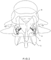
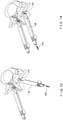
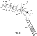
- a system 100 for posterior fusion comprises an implant 102 sized and shaped for insertion into a facet joint to facilitate fusion of first and second vertebrae 10, 12.
- the system 100 further comprises an insertion tool 104 including an impactor 146 for facilitating impaction of the implant 102 into the facet joint (i.e., the joint between a superior articular process 14 of the second vertebra 12 and an inferior articular process 16 of the first vertebra 10 directly above it) and an aiming guide 106 for guiding first and second bone fixation elements 108, 109 through first and second holes 110, 112, respectively, of the implant 102 to fix the implant 102 to the vertebrae 10, 12.
- Each spinal motion segment (e.g., vertebra 10, 12) includes two facet joints (i.e., a right side and a left side) such that the system 100 may include a second implant 102'.
- the implant 102 as described below, may be configured to be implanted into one of the two facet joints (e.g., the right facet joint) while the second implant 102' may be configured to be implanted into the other of the two facet joints (e.g., the left facet joint).
- the second implant 102' is not described in detail, the second implant 102' may be substantially similar to the implant 102 and, in particular, may be a mirror image of the implant 102.
- the first and second implants 102, 102' may be colour-coded and/or labelled to indicate whether the implants 102, 102' are configured for the right or left facet joint.
- the implant 102 is substantially wedge-shaped extending along a longitudinal axis L and tapering from a first end 114 which, when implanted into the facet joint in a desired configuration, faces a posterior side of the spine, to a second end 116 which, when implanted into the facet joint faces a ventral side of the spine.
- the tapered second end 116 facilitates insertion of the implant 102 into the facet joint.
- the implant 102 is defined by first and second substantially planar surfaces 118, 120 which extend from the first end 114 to the second end 116 at an angle with respect to the longitudinal axis L to form the tapered wedge-shape, and third and fourth lateral surfaces 130, 132 which connect the first and second surfaces 118, 120.
- first surface 118 engages the inferior articular process 16 of the first vertebra 10 while the second surface 120 engages the superior articular process 14 of the second vertebra 12.
- the first and second surfaces 118, 120 each include a plurality of ribs 122 projecting therefrom and extending from the first end 114 to the second end 116 to guide the implant 102 into the joint and facilitate engagement with the first and second vertebra 10, 12.
- the implant 102 also includes a plurality of openings 180 extending through it from the first surface 118 to the second surface 120 to promote bony growth through the implant, increasing stability after fusion.
- the implant 102 includes a cut out 182 extending proximally from the second end 116 (i.e., toward the first end 114) and extending through the implant from the first surface 118 to the second surface 120. The cut out 182 minimizes sharp edges that may be present to accommodate a central opening 124 through which a K-wire or similar device may be positioned.
- the implant 102 also includes a central opening 124 extending through it from the first end 114 to the second end 116 along the longitudinal axis L.
- the central opening 124 is sized and shaped to accommodate a guide wire such that the implant 102 may be slid along a guide wire inserted into the facet joint.
- the first and second holes 110, 112 of this construction extend through the implant 102 on opposing sides of the central opening 124.
- the first hole 110 extends through it from the first end 114 to the first surface 118 such that a first hole axis of the first hole 110 is angled with respect to the longitudinal axis L.
- the first hole 110 may include a threading 126 along all or a portion of an inner surface thereof for engaging a threading on a head of a first bone fixation element 108 inserted through it.
- the first bone fixation element 108 may be received in the first hole 110 along the first hole axis A such that a shaft thereof is inserted into the inferior articular process of the first vertebra 10.
- the second hole 112 extends through it from the first end 114 to the second surface 120 along a second hole axis B of the second hole 112 angled with respect to the longitudinal axis L in a direction opposite the first hole axis A.
- first axis A may be angled with respect to the longitudinal axis L at an angle between approximately 10° and 45° and, more particularly, between 25° and 30° while the second axis B may be angled with respect to the longitudinal axis L at an angle between approximately -10° and -45° and, more particularly, between -25° and -30°.
- the second hole 112 may include threading 128 along all or a portion of an inner surface thereof for engaging a threading on a head of a second bone fixation element 109 inserted through it.
- the second bone fixation element 109 may be received within the second hole 112 along the second hole axis B such that a shaft thereof is inserted into the inferior articular process of the second vertebra 12.
- first and second holes 110, 112 at the first end 114 may be open to and overlap with the central opening 124, as shown.
- a guide wire inserted through the central opening 124 prevents bone fixation elements 108, 109 from being inserted through the first and second openings 110, 112.
- one or both of the first and second holes 110, 112 may be formed as a distinct hole, separated from the central opening 124.
- the first end 114 is configured for attachment to the aiming guide 106.
- third and fourth surfaces 130, 132 of this construction include recesses 134, 136, respectively, at the first end 114 which permit a portion of the aiming guide 106 to be received therein.
- the recesses 134, 136 may also include protrusions 138, 140, respectively, which extend therefrom to engage a portion of the aiming guide 106 received therein.
- the protrusions 138, 140 may, for example, be dome shaped to facilitate engagement with the aiming guide 106 while also permitting the aiming guide 106 to pivot with respect to the implant 102 about an axis of rotation R.
- the protrusions 138, 140 may be coaxial with the axis of rotation R.
- the axis R may be substantially perpendicular to the third and fourth lateral surfaces 130, 132.
- the protrusions 138, 140 are described as dome-shaped, the protrusions 138, 140 may be any of a variety of shapes so long as the protrusions 138, 140 permit engagement with the aiming guide 106 and pivoting of the implant 102 relative thereto.
- the first end 114 also includes first and second abutting surfaces 142, 144, respectively, extending substantially parallel to the rotation axis R and at an angle with respect to the longitudinal axis L to define a maximum angle of pivot of the implant 102 relative to the aiming guide 106.
- the angles of the first and second abutting surfaces 142, 144 correspond to the angle of the first and second axes A, B of the first and second openings 110, 112, respectively.
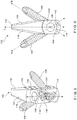
- the impactor 146 and the aiming guide 106 of the insertion tool 104 are releasibly coupled to one another via, for example, a friction fit.
- the impactor 146 includes a head 148 and a shaft 150 extending distally therefrom to a distal end 152 configured to be attached to the aiming guide 106.
- the distal end 152 may, for example, receive a portion of the aiming guide 106 therein.
- the impactor 146 also includes a channel 170 extending through it along a longitudinal axis for receiving a guide wire through it.
- the head 148 may have a larger cross-sectional area than the shaft 150, providing a surface on which a force may be exerted to impact the implant 102 into the facet joint.
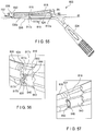
- the aiming guide 106 includes a body 154 extending along a longitudinal axis L' from a proximal end 156 configured to be attached to the distal end 152 of the impactor 146 to a distal end 158 configured to be coupled to the implant 102.
- the body 154 further includes a central channel 168 extending longitudinally through it from the proximal end 156 to the distal end 158 such that when the aiming guide 106 and/or impactor 146 is coupled to the implant 102, the central opening 124 of the implant 102 is aligned with the central channel 168 of the aiming guide 106 and the channel 170 of the impactor 146 to receive a guide wire through it.
- the body 154 also includes a first guide channel 172 and a second guide channel 174, each of which extend longitudinally through it from the proximal end 156 to the distal end 158 in a position corresponding to the first and second openings 110, 112, respectively, of the implant 102 such that when coupled thereto, drills and/or bone fixation elements 108, 109 may be guided through the guide channels into the first and second openings 110, 112.
- the first and second guide channels 172, 174 may overlap with the central channel 168 depending on a configuration of the first and second openings 110, 112 of the implant 102.
- the proximal end 156 may, for example, have a reduced cross-section area sized and shaped to be received within the distal end 152 of the impactor 146 via a friction fit.
- the aiming guide 106 and the impactor 146 are coupled such that the longitudinal axes thereof are substantially coaxial with one another.
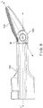
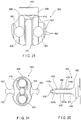
- the distal end 158 of the aiming guide 106 may include jaws 160 including first and second jaw members 160a, 160b extending distally therefrom on opposing sides of the longitudinal axis L'. The jaws 160 receive a portion of the first end 114 between the first and second jaw members 160a, 160b seated within the recesses 134, 136 of the implant 102.
- the jaw members 160a, 160b also include recesses along inner surfaces thereof sized and shaped to receive the protrusions 138, 140 therein to engage the implant 102.
- the body 154 may be at least partially formed of a compliant material and include a slot 166 extending along a portion thereof from an exterior surface to an interior surface of the body 154 to permit the jaw members 160a, 160b to be flexed apart from one another such that the first end 114 of the implant 102 may be received between the jaw members and the arms 160 extended over the protrusions 138, 140 to be "snapped" over the jaw members.
- the slot 166 may, for example, be substantially Z-shaped including first and second portion 166a, 166b extending substantially parallel to the longitudinal axis L' and a third portion 166c connecting the first and second portions 166a, 166b to form a continuous slot 166.
- the aiming guide 106 further includes a locking rod 162 which may be inserted into a locking channel 164 extending along an exterior of the body 154 to lock the arms 160 in the undeformed configuration, preventing the implant 102 from being inadvertently disengaged therefrom.
- the locking channel 164 extends along the body 154 and intersects with the slot 166 such that the when the locking rod 162 is inserted through it, the jaws 160 are prevented from moving apart from one another, thus locking the aiming guide 106 and the implant 102 together.
- the locking channel 164 may, for example, extend longitudinally along the body 154 to intersect with the third portion 166c of the slot 166.
- the system 100 may be used in a minimally invasive procedure via a small incision along a portion of the spine corresponding to a position of the vertebrae 10, 12.
- the implant 102 would be difficult to locate via the small incision.
- the locking rod 162 may be removed from the locking channel 162 such that the jaws 160 may be flexed apart from one another by the slot 166.
- the aiming guide 106 is pivotable with respect to the implant 102 about the rotation axis R such that the longitudinal axis L of the implant 102 may be angled with respect to the longitudinal axis L' of the aiming guide 106.
- the aiming guide 106 may be pivoted between a neutral position in which the central channel 168 is aligned with the central opening 124 of the implant 102 (i.e., the longitudinal axes L, L' are coaxial), a first position in which the first guide channel 172 is substantially coaxial and aligned with the first opening 110 and a second position in which the second guide channel 174 is substantially coaxial and aligned with the second opening 112.
- the first and second positions are defined by the first and second abutting surfaces 142, 144 of the implant 102.
- the first abutting surface 142 abuts a portion of the distal end 158 of the body 154 of the aiming guide 106, preventing the aiming guide 106 from moving beyond a desired maximum angle of pivot relative to the implant 102 in a first direction.
- the second abutting surface 144 abuts a portion of the distal end 158, preventing the aiming guide 106 from moving beyond a desired maximum angle of pivot relative to the implant 102 in a second direction.
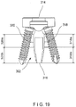
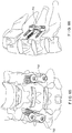
- Figs. 10 to 16 show a surgical method using the system 100.
- the method comprises inserting a first guide wire 176 into a facet joint between the first and second vertebrae 10, 12.
- the first guide wire 176 may be inserted into a right facet joint.
- a second guide wire 178 may be inserted into the other facet joint (e.g., left facet joint).
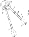
- the insertion tool 104 may be coupled to the implant 102, as described above, such that longitudinal axes of the impactor 146, the aiming guide 106 and the implant 102 are substantially coaxial with one another.
- the locking rod 162 may be inserted into the locking channel 164 to ensure that the aiming guide 106 and the implant 102 remain coupled during the entire surgical process.
- the coupled insertion tool 104 and the implant 102 may then be slid over the first guide wire 176, as shown in Fig. 11 , such that the first guide wire 176 is received within the central openings 124 of the implant 102 and the central channels 170, 168 of the impactor 146 and the aiming guide 106 such that the implant 102 is in the neutral position relative to the aiming guide 106.
- the guide wire 176 ensures that the impactor 146 and the implant 102 are aligned such that an impacting tool may be used to impact the implant 102 by applying a force to the head 148 of the impactor 146 such that the implant 102 penetrates a capsule covering the facet joint and is inserted into the facet joint.
- the tapered second end 116 of the implant 102 facilitates penetration of the capsule.
- a second insertion tool 104' which is substantially similar to the insertion tool 104, may be coupled to the second implant 102' and similarly slid over the second guide wire 178. Although not discussed in detail, all of the steps described in relation to the insertion tool 104 and the implant 102 may be repeated for the second insertion tool 104' and the second implant 102'.
- the figures show the implant 102' and the insertion tool 104', it may be desired to implant only a single implant 102 in either the right or left facet joint.
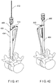
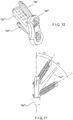
- the impactor 146 may be disengaged from the aiming guide 106 such that only the aiming guide 106 and the implant 102 remain mounted over the first guide wire 176, as shown in Fig. 12 .
- the first guide wire 176 may then be removed such that the aiming guide 106 may be pivoted with respect to the implant 102.
- the aiming guide 106 is pivoted about the rotation axis R of the implant 102 until the aiming guide 106 is in the first position (i.e., the first abutting surface 142 of the implant 102 abuts a portion of the distal end 158 of the aiming guide 106), as shown in Fig.
- first guide channel 172 is aligned with the first opening 110.
- a drill or awl may be inserted through the first guide channel 172 to drill a hole into inferior process 16 of the first vertebra 10 in alignment with the first axis A of the first opening 110.
- the bone fixation element 108 may be inserted through the first guide channel 172 and into the first opening 110 such that a head of the fixation element 108 engages the first opening 110 while a shaft extends into the inferior process 16 fixing the implant 102 to the first vertebra 10.
- the aiming guide 106 may then be pivoted to the second position relative to the implant 102 (i.e., the second abutting surface 144 of the implant 102 abuts a portion of the distal end 158 of the aiming guide 106) such that the second guide channel 174 is aligned with the second opening 112 of the implant 102.
- a hole may be drilled in the superior articular process 14 of the second vertebra 12 via the second guide channel 174 and the bone fixation element 109 inserted through it to engage the second opening 112.
- a head of the bone fixation element 109 engages the second opening while a shaft of the bone fixation element 109 extends into the superior articular process 14 such that the implant 102 is fixed to the second vertebra 12.
- the second bone fixation element 109 may be inserted into the second opening 112 prior to insertion of the first bone fixation element 108 into the first opening 110.
- the aiming guide 106 is moved to the neutral position and the locking rod 162 removed therefrom so that the aiming guide 106 may be decoupled from the implanted implant 102, as shown in Fig. 15 .
- the above- described steps may be similarly repeated for the implant 102' using an aiming guide 106' of the insertion tool 104', until the implant 102' is fixed within the second facet joint, as shown in Fig. 16 .
- the implantation of both implants 102, 102' is not required. It may be desired to implant a single implant 102 in either of the right or left facet joint.
- an implant 202 may be substantially similar to the implant 102, described above in relation to the system 100.
- the implant 202 may have a body 203 that is substantially wedge-shaped, tapering from a first end 214 to a second end 216 along a longitudinal axis 2L.
- the implant 202 is defined by first and second substantially planar surfaces 218, 220 which extend from the first end 214 to the second end 216 at an angle with respect to the longitudinal axis 2L to form the tapered wedge shape, and third and fourth lateral surfaces 230, 232 which connect the first and second surfaces 218, 220.
- the implant 202 further includes a head portion 290 attached to the first end 214 of the body 203 and having a width (i.e., a distance of the head portion 290 extending across the longitudinal axis 2L) greater than a width W of the first end 214 of the body 203 (i.e., a distance between the first and second surfaces 218, 220 at the first end 214).
- the width may be approximately 10 mm.
- the head portion 290 may be substantially circular such that width corresponds to a diameter of the head portion 290.
- the head portion 290 may be any of a variety of shapes and sizes so long as the head portion 290 is wider than the first end 214 of the body 203.
- the larger width of the head portion 290 acts as a stop to prevent the head portion 290 from being inserted into the facet joint. Thus, the implant 202 may be easily removed, if so desired.
- the head portion 290 may also include a coupling feature configured for attachment to an insertion and/or removal instrument.
- the implant 202 includes a central opening 224 extending through the head portion 290 and the body 203 along the longitudinal axis 2L to accommodate a guide wire through it along with first and second openings 210, 212 extending through it to accommodate bone fixation elements 208, 209.
- the first and second openings 210, 212 extend only through the head portion 290.
- the first opening 210 extends through the head portion 290 along a first axis 2A, which is angled with respect to the longitudinal axis 2L in a first direction such that the bone fixation element 208 may be inserted through the first opening 210 along the first axis 2A and into a first vertebra of the facet joint.
- the second opening 212 extends through the head portion 290 along a first axis 2B, which is angled with respect to the longitudinal axis 2L in a second direction opposite the first direction such that the bone fixation element 209 may be inserted through the second opening 212 along the first axis 2B and into a second vertebra of the facet joint.
- the central axis, the first axis 2A may be angled with respect to the longitudinal axis 2L at an angle of between approximately 5° and 45° and, more particularly, between 10° and 20° while the second axis 2B may be angled with respect to the longitudinal axis 2L at an angle of between approximately 10° and 20°.
- first and second axes 2A, 2B may be at any of a variety of angles with respect to the longitudinal axis 2L so long as the bone fixation elements 208, 209 received within the openings 210, 212 are inserted into first and second vertebrae of the facet joint.
- a depth D of the head portion 290 (i.e., a distance of the head portion 290 along the longitudinal axis 2L) may be between approximately 2.0 to 3.0 mm such that the first and second holes 210, 212 may receive heads of the first and second bone fixation elements 208, 209, respectively, therein. Inner surfaces of the holes 210, 212 may include threading to engage threads along the heads of the first and second bone fixation elements 208, 209 so that shafts thereof extend into the first and second vertebrae of the facet joint to fix the implant 202 thereto.
- the implant 202 may also be substantially symmetrical about the longitudinal axis 2L such that the implant 202 may be utilized for either facet joint - i.e., a left side or a right side - and would not require a "left" and "right” side configuration.
- the body 203 may have a substantially symmetrical wedge shape, and the first and second axes 2A, 2B of the first and second openings 210, 212 may also be symmetrical about the longitudinal axis 2L.
- the implant 202 may be implanted into the facet joint by sliding the implant 202 over a guide wire received within the central opening 224 until the head portion 290 prevents further movement thereof. The guide wire may then be removed so that bone fixation elements 208, 209 may be inserted through the first and second openings 210, 212, respectively, and into the first and second vertebrae to fix the implant 202 thereto.
- the implants 102, 202 have been described as wedge-shaped. However, other implant shapes are possible.
- an implant 302 is similar to the implants 102, 202, with a first end 314 and a second end 316 along a longitudinal axis, and first and second surfaces 318, 320, respectively.
- the implant 302 is used substantially the same the manner described for implant 202.
- the surfaces 318, 320 define a more pronounced transition from a second end 316 to a first end 314 along the longitudinal axis.
- the opening of the facet joint with the implant 302 is more abrupt.
- the relatively abrupt transition is provided by a shape of the implant 302 defined by the first and second surfaces 318, 320 and an insertion surface at the second end 316 that connects the first and second surfaces 318, 320.
- Each of the first and second surfaces 318, 320 has first regions 318a, 320a, respectively, and second regions 318b, 320b, respectively.
- the portions of the surfaces 318, 320 in the first regions 318a, 320a are substantially planar and substantially parallel to each other.
- the first and second surfaces 318, 320 are shaped to provide a smooth insertion transition in an insertion direction from the second end 316 to the first end 314.
- the smooth transition may be provided by portions of the surfaces 318, 320 in the second regions 318b, 320b defining curved or planar surfaces that widen from the second end 316 in a direction toward the first regions 318a, 320a.
- the insertion surface defined at the second end 316 is, in normal use, the first part of the implant 302 that contacts the facet joint during insertion.
- the insertion surface provides the initial opening of the facet joint.
- the insertion surface could be described as having a blunt profile.
- the blunt profile may be defined by an insertion surface which is planar, arced, bullet-shaped, and other surface shapes.
- the insertion surface of the second end 316 is relatively wider to provide a more abrupt opening. Since the inferior and superior surfaces of facet joint are substantially parallel to one another the parallel planar portions 318a, 320b of the surfaces 318, 320 fit well anatomically to the facet joint.
- system 400 can comprise an implant 402 and an implant holder 406.
- the implant 402 may be substantially similar to the implant 302, described above, comprising a body 403 sized and shaped for insertion into a facet joint and extending from a first end 414 to a second end 416, and a head portion 490 attached to the first end 414.
- the system 400 may further comprise a facet joint finder 530, as shown in Figs. 31 and 32 , for locating the facet joint, a reamer 550, as shown in Figs. 31 and 33 , for removing soft tissue and creating a seating surface for the implant 402 and a curette 560, as shown in Figs. 34 and 35 , for removing cartilage from the facet joint to facilitate insertion of the implant 402 therein, as will be described in further detail below.
- the implant 402 includes a central opening 424 extending through the head portion 490 and the body 403 along a longitudinal axis 4L to accommodate a guide wire through it along with first and second openings 410, 412 extending through the head portion 490 to receive bone fixation elements 408, 409 through the guide channels.
- the first opening 410 extends along a first axis 4A, which is angled with respect to the longitudinal axis 4L, such that a first bone fixation element 408 be inserted through the first opening 410 extends along the first axis 4A which, when the implant 402 is in a desired position will aim the first bone fixation element 408 along a desired path into a first vertebra of a facet joint.
- the second opening 412 extends along a second axis 4B angled with respect to the longitudinal axis 4L in a second direction opposite the first axis 4A such that, when the implant 402 is in the desired position, a second bone fixation element 409 inserted through the second opening 412 extends along the second axis 4B into a second vertebra along a desired path.
- the angle between the first axis 4A and the longitudinal axis 4L and the angle between the second axis 4B and the longitudinal axis 4L in this construction are substantially equal to one another such that the implant 402 is substantially symmetrical with respect to the longitudinal axis 4L.
- the implant holder 406 is used to insert the implant 402 into the facet joint and guide the bone fixation elements 408, 409 into the first and second openings 410, 412, respectively.
- the head portion 490 of the implant 402 according to this construction also includes a recess 496 along opposing portions of a periphery thereof for engaging a portion of the implant holder 406.
- a shape of the body 403 transitions from the first end 414 to the second end 416 and is defined by first and second surfaces 418, 420 thereof.
- each of the first and second surfaces 418, 420 has first regions 418a, 418b, respectively, and second regions 420a, 420b, respectively.
- the first regions 418a, 420a are substantially planar and parallel to one another while the second regions 418b, 420b taper toward the second end 416 to provide a smooth insertion transition.
- the body 403 also includes a plurality of ribs 422 projecting from each of the first and second surfaces 418, 420 to guide the implant 402 into the facet joint and facilitate engagement with the first and second vertebra.
- the ribs 422 extend along the surfaces 418, 420 from the first end 414 to the second end 416.
- the ribs 422, however, further include teeth 492 or a jagged edge extending along them to enhance a grip between the implant and the surrounding tissue to prevent the implant 402 from being inadvertently pulled out of a facet joint into which it has been inserted.
- the teeth 492 are angled with peaks 494 thereof pointing toward the first end 414 to increase a pull-out resistance of the implant 402.
- the implant 402 includes larger first and second holes 480, 481 extending through the body 403.
- the first hole 480 extends through a first portion of the body 403 from the first surface 418 to the second surface 420 on a first side of the central opening 424.
- the second hole 481 extends through a second portion of the body 403 from the first surface 418 to the second surface 420 on a second side of the central opening 424 opposite the first side.
- the first and second holes 480, 481 are sized and shaped to permit the holes 480, 481 to be filled with bone graft material to promote bone growth during the implantation process.
- the implant holder 406 includes a guide body 454 including a central channel 472 extending from a proximal end 456 to a distal end 458 and a shaft 498 slidably received within the central channel 472.
- the shaft 498 extends along a longitudinal axis to a distal end 500 which is configured to engage the head portion 490 of the implant 402.
- the distal end 500 includes jaw members 460a, 460b extending distally therefrom on opposing sides of the shaft 498.
- the jaw members 460a, 460b are biassed away from one another such that the head portion 490 may be received between them.
- the guide body 454 is slidable over the shaft 498 between an implant receiving configuration, as shown in Figs. 26 and 27 , in which the jaw members 460a, 460b receive the head portion 490 between them and a closed configuration, as shown in Figs. 28 and 29 , in which the jaw members 460a, 460b are moved toward one another to engage the recesses 496 to hold the implant 402 between them.
- the guide body 454 includes a central channel 472 sized and shaped to slidably house the shaft 498 therein and a guide channel 474 extending through the guide body 454 at an angle relative to the central channel 472.
- the central channel 472 extends through the guide body 454 along a path oriented so that, when the shaft 498 engages the implant 402, the central channel 472 is aligned with the longitudinal axis 4L of central opening 424.
- the guide channel 474 extends through the guide body 472 such that when the shaft 498 engages the implant 402, the guide channel 474 is aligned with one of the first and second axes 4A, 4B of the first and second openings 410, 412, respectively.
- the guide body 454 is thus rotatable about the shaft 498 so that, when coupled to the implant 402, the guide channel 474 may be moved between a first hole configuration in which the guide channel 474 is aligned with the first opening 410 and a second hole configuration in which the guide channel 474 is aligned with the second opening 412.
- the guide body 454 also includes a locking mechanism 508 including a locking tab 502 biassed toward a centre of the central channel 472 to engage portions of the shaft 498 to fix the guide body 454 relative to the shaft 498 in one of the implant receiving or closed configuration and/or the first hole and second hole configurations.
- the locking mechanism 508 also includes a release lever 510 which may be used to draw the locking tab 502 out of engagement with the portions of the shaft 498 as will be described in further detail below.
- the shaft 498 extends longitudinally from a proximal end 512 to the distal end 500 and includes a lumen 514 extending through it.
- the lumen 514 is sized and shaped to permit the implant holder 406 to be slid over a guide wire to insert the implant 402 into the facet joint.
- the proximal end 512 is configured to be coupled to an end cap 516 which may be used to hold the shaft 498 while the body 454 is moved between the implant receiving and closed configurations.
- the end cap 516 also includes a corresponding lumen 520 such that the guidewire may extend through both the end cap 516 and the shaft 498.
- the distal end 500 includes jaw members 460a, 460b for engaging the head portion 490 of the implant.
- the jaw members 460a, 460b may be formed via, for example, a slot 466 extending along a length of a distal portion of the shaft 498.
- the jaw members 460a, 460b may further include protrusions 518 extending radially inward from a portion thereof, the protrusions 518 sized and shaped to correspond to the recesses 496 in the head portion 490 of the implant 402.
- the shaft 498 includes first and second locking recesses 504a, 504b extending along a proximal portion of the shaft 498 for engaging the locking tab 502 to lock the implant holder 406 in the implant receiving configuration.
- the first and second locking recesses 504a, 504b in this construction are substantially diametrically opposed from one another.
- the locking tab 502 may be received in either of the first and second locking recesses 504a, 504b to lock the implant holder in the implant receiving configuration.
- the shaft 498 also includes a locking hole 506 extending laterally through it distally of the first and second locking recesses 504a, 504b.
- the locking hole 506 is sized and shaped to engage the locking tab 502 to lock the implant holder 406 in the closed configuration and one of the first and second hole receiving configurations.
- the locking hole 506 extends entirely through the shaft 498 from a first opening 507a to a second opening 507b substantially opposing the first opening 507a.
- the first opening 507a may be longitudinally aligned with the first locking recess 504a while the second opening 507b is longitudinally aligned with the second locking recess 504b.
- the locking hole 506 is positioned distally of the first and second locking recesses 504a, 504b such that when the locking tab 502 engages the second locking hole 506, the implant holder 406 is locked in the closed configuration.
- the distal end 500 of the shaft 498 may be positioned over the head portion 490 of the implant 402.
- a user moves the release lever 510 to disengage the locking tab 502 from the first locking hole 504 and slides the guide body 454 distally over the jaw members 460a, 460b until the implant holder 406 is in the closed configuration and the locking tab 502 engages the second locking hole 506.
- the guide body 454 is moved longitudinally over the jaw members 460a, 460b such that the protrusions 518 engage the recesses 496 of the head portion 490.
- the distal portion of the shaft 498 also includes a first guide channel 522 and a second guide channel 524 extending through it.
- the first guide channel 522 extends through the distal portion of the shaft 498 at an angle relative to the longitudinal axis of the shaft 498 corresponding to an angle between the first axis 4A of the first opening 410 and the longitudinal axis 4L of the implant 402.
- the second guide channel 524 extends through the distal portion of the shaft 498 at an angle relative to the longitudinal axis of the shaft 498 corresponding to an angle between the second axis 4B of the second opening 412 and the longitudinal axis 4L of the implant 402.
- the guide channel 474 of the body 454 is aligned with one of the first and second guide channels 522, 524 of the shaft 498 such that one of the bone fixation elements 408, 409 may be guided through it into one of the first and second openings 410, 412 of the implant 402.
- the locking tab 502 engages the first opening 507a of the locking hole 506
- the implant holder 406 is locked in the first hole configuration such that the guide channel 474 is aligned with the first guide channel 522 of the shaft 498.
- the implant holder 406 When the locking tab 502 engaging the second opening 507b of the locking hole 506, the implant holder 406 is locked in the second hole configuration such that the guide channel 474 is aligned with the second guide channel 524 of the shaft 498. As discussed above, the implant holder 406 may be moved between the first and second hole configurations by pulling the release lever 510 to disengage the locking tab 502 from one of the first and second openings 507a, 507b of the locking hole 506 and rotating the guide body 454 about the shaft 498 until the locking tab 502 engages the other of the first and second openings 507a, 507b.
- the facet joint finder 530 includes a shaft 532 extending longitudinally from a proximal end 534 to a distal end 536 attached to a joint finding tip 538 and a lumen extending through it to receive a guidewire therein.
- the joint finding tip 538 is sized and shaped to be inserted into a facet joint of a patient and includes first and second planar surfaces 542, 544 which taper toward one another to a distal end 546 thereof to facilitate insertion into the facet joint.
- a length of the joint finding tip 538 is selected to correspond to a length of the implant 402.
- the joint finding tip may also include a longitudinal slot 540 extending along them to accommodate a guidewire that is wider than a distance between the first and second planar surfaces 542, 544.
- the facet joint finder 530 may also include a stop 548 extending radially outward from a portion of the shaft 532 immediately proximal the joint finding tip 538. The stop 548 prevents a reamer 550 which may be used in conjunction with the facet joint finder 530 from extending distally past the stop 548.
- the reamer 550 extends longitudinally from a proximal end 552 to a distal end 554 and includes extending through it a lumen sized and shaped to receive the shaft 532 of the facet joint finder 530.
- the distal end 554 of the reamer 550 has, for example, a substantially circular distal face 556 including blades 558 extending along them for removing soft tissue and creating a seating surface for receiving the head portion 490 of the implant 402.
- the curette 560 includes a shaft 562 extending longitudinally from a proximal end 564 to a distal end 566 attached to an implant-shaped tip 568 and a lumen extending through it to accommodate a guidewire within it. As shown, the curette 560 may also be used in conjunction with the reamer 550 described above. Thus, the shaft 562 is sized and shaped to be slidably received within the lumen of the reamer 550.
- the implant-shaped tip 568 has a size and shape corresponding to the body 403 of the implant 402 to be inserted into the facet joint such that the tip 568, when inserted into the facet joint, removes cartilage therefrom to accommodate insertion of the implant 402 therein.
- the curette 560 may also include a stop (not shown) extending radially outward from a portion of the shaft 562 proximal of the implant-shaped tip 568 such that when the curette is coupled with the reamer 550, the reamer 550 is prevented from moving distally past the stop.
- Figs. 36 to 43 show a surgical technique using the system 400.
- the surgical technique comprises inserting a guide wire 570 into the facet joint so that it extends longitudinally to a distal end including a flat tip 572 and threads 574, as shown in Fig. 32 , or teeth, as shown in Fig. 35 , extending along a length of the guide wire 570 distally of the flat tip 572 to facilitate holding within the bone.
- the guide wire 570 can be inserted into the joint using an aiming guide 576 including x-ray markers enabling visualization of the implant placement within the facet joint.
- the x-ray markers may include, for example, pins to indicate a width of the implant 402 to be inserted and a ring to show a size of the head portion 490.
- a soft-tissue retractor 582 is then slid over the guide wire 570 and/or aiming shaft 578 to remove soft tissue surrounding the area in which the implant 402 is to be inserted.
- the guide wire 570 is placed within the facet joint via the facet joint finder 530, as shown in Fig. 39 .
- the joint finding tip 538 is inserted into the facet joint in which the implant 402 is to be inserted.
- the guide wire 570 is inserted through the shaft 532 of the facet joint finder 530 until the distal end 572 of the guide wire 570 is inserted into the facet joint.
- the distal end 572 should not be inserted more than a desired distance (e.g., 15mm) into the joint to prevent damage to the neural structures.
- the reamer 550 is slid over the shaft 532 of the facet joint finder 530 until a distal end of the reamer 550 contacts the stop 548.
- the distal face 556 of the reamer 550 is used to create a surface for implant seating.
- the reamer 550 and the facet joint finder 530 may then be removed, leaving the guide wire 570 inserted in the facet joint.
- the soft tissue retractor 582 is then slid over the guide wire 570 to remove the soft tissue surrounding the implant area.
- the curette 560 is slid over the guide wire 570 until the implant-shaped tip 568 is inserted into the facet joint to remove the cartilage in the facet joint, creating optimal conditions for bony fusion. If the surrounding bone has not been reamed already during the guide wire 570 placement, the reamer 550 may be slid over the shaft 562 of the curette 560 so that the distal face 556 may create a surface for implant seating. Once the cartilage has been removed, the curette 560 and/or the reamer 550 may be removed, leaving the guide-wire 570 inserted in the facet joint.
- the implant 402 may be coupled to the implant holder 406.
- the implant holder 406 in the implant receiving configuration, is positioned over the implant 402 such that the head portion 490 of the implant 402 is received between jaw members 460a, 460b of the shaft 498.
- the implant holder 406 may be locked in the implant receiving configuration via the locking mechanism 508.
- the user pulls the release lever 510 of the locking mechanism 508, to slide the body 454 of the implant holder 406 distally over the shaft 498 until the implant holder is locked in the closed configuration and the head portion 490 of the implant 402 is gripped between the jaw members 460a, 460b, as shown in Fig. 41 .
- the implant 402 is then inserted into the facet joint by sliding the implant holder 406 over the guide wire 507. Upon insertion of the implant 402 into the facet joint, the guide wire may be removed.
- the central channel 472 of the body 454 and the shaft 498 received therein are aligned with the longitudinal axis 4L of the central opening 424 of the implant 402 while the guide channel 474 of the implant holder 406 is aligned with one of the first and second axes 4A, 4B of the first and second openings 410, 412.
- an awl may be inserted through the guide channel 474 and into the first opening 410 along the first axis 4A to create a hole in the first vertebra of the facet joint.
- the bone fixation element 408 may then be inserted through the guide channel 474 and into the first opening 410 such that a shaft thereof extends into the hole formed in the first vertebra and a head thereof engages a threading extending along an interior of the first opening 410.
- an awl may be used to form a hole in the second vertebra of the facet joint via the guide channel 474 and the second bone fixation element 409 may be inserted through it such that a shaft thereof extends into the second vertebra and a head thereof engages a threading extending along an interior of the second opening 412.
- the guide channel 474 is shown aligned initially with the first opening 410 of the implant 402, the guide channel 474 may initially be aligned with the second opening 412 such that the bone fixation element 409 is inserted through the second opening 412 and into the second vertebra prior to insertion of the bone fixation element 408 through the first opening 410 and the first vertebra.
- the implant holder 406 may be disengaged from the implant 402 and removed from the body, as shown in Fig. 43 .
- the implant holder 406 may be removed by pulling the release lever 510 to move the implant holder to the implant receiving configuration to disengage the implant 402.
- the implant holder 406 may be disassembled by removing the end cap 516 from the proximal end 512 of the shaft 498 so that the body 454 may be slidably removed from the shaft 498.
- the jaw members 460a, 460b of the shaft 498 revert to their biassed, open configuration such that the implant 402 is released from between them.
- Proper positioning of the implant 402 and the bone fixation elements 408, 409 may be ensured by visually inspecting the implant 402 and/or viewing x-ray images showing the positioning of the implant 402 in the facet joint.
- an implant 602 may be substantially similar to the implants 202, 302 and 402, described above, comprising a body 603 extending distally from a head portion 690.
- the body 603 may be wedge-shaped, similarly to the implant 202.
- the body 603 may be substantially similar to the bodies 303, 403 including first and second planar surfaces 618, 620 having first portions 618a, 620a substantially parallel to one another and second portions 618b, 620b tapering toward one another to a distal end 616 thereof to facilitate insertion into a facet joint.
- the implant 602 includes a central opening 624 extending longitudinally through the head portion 690 and the body 603 along a longitudinal axis 6L.
- the implant 602 does not include first and second openings extending through it at an angle relative to the longitudinal axis 6L. Rather, a proximal portion of the central opening 624 is sized and shaped to receive a bone fixation element 608 therein.
- the proximal portion of the central opening 624 may include a threading 626 extending along them to engage a threading 627 along a shaft 609 of the bone fixation element 608.
- a diameter of a shaft is larger than a distance between the first and second planar surfaces 618, 620 of the implant 602 such that the proximal portion of the central opening 624 is laterally open to an exterior thereof.
- the bone fixation element 608 may be inserted into along the longitudinal axis 6L into the central opening 624 to fix the implant 602 within the facet joint.
- the threads 627 along the shaft 609 will engage the surrounding bone to fix the implant 602 therein.
- the head 690 is of a larger width and may act as a stop for preventing the head portion 690 from being inserted into the facet joint.
- the body 603 also comprises a plurality of openings 680 extending through it from the first surface 618 to the second surface 620.
- Figures 45 to 64 depict a system which includes an implant 702 configured for use with an insertion instrument 802.
- an insertion instrument 802. As will be described in greater detail hereinafter, the exemplary system described hereafter is configured for use in cervical spine fixation procedures.
- the exemplary implant 702 may be substantially similar to the implants 102, 202, described above. Similarly to the implant 102, the implant 702 has a body 703 extending distally from a head portion 790.
- the body 703 may be substantially wedge-shaped, tapering from a first end 714 to a second end 716 along a longitudinal axis 7L.
- the longitudinal axis 7L of the body 703 extends at a non-perpendicular angle from a plane housing the head portion 790.
- an angle ⁇ 1 between the head portion 790 and the longitudinal axis 7L is approximately 45°, although any other angle may be employed.
- the angle ⁇ 1 could be any angle between 30° to 90°.
- the body 703 may further comprise a plurality of ribs 722 projecting from each of first and second surfaces 718, 720 of the body 703 to facilitate engagement with first and second adjoining vertebra.
- the ribs 722 extend along the surfaces 718, 720 from the first end 714 to the second end 716.
- the ribs 422 further include teeth 792 or a jagged edge extending along them to enhance a grip between the implant 702 and the surrounding tissue to prevent the implant 702 from being inadvertently pulled out of a cervical joint into which it has been inserted.
- the teeth 792 are angled with peaks 794 thereof pointing toward the first end 714 to increase a pull-out resistance of the implant 702.
- a width of the head portion 790 may be approximately 8 mm
- a height may be approximately 17.5 mm
- a thickness may be approximately 2.2 mm, although any other measurements may be used.
- the second end 716 of the body 703 may be approximately 0.7 mm in thickness although any other measurement may be used.
- the implant 702 further includes first and second openings 710, 712 extending through the head portion 790 to receive bone fixation elements (e.g., bone screws) 708, 709.
- the first opening 710 extends along a first axis 7A, which is substantially parallel to the longitudinal axis 4L, such that the first bone screw 708 inserted through the first opening 710 extends along the first axis 7A which, when the implant 702 is in a desired position aims the first bone screw 708 along a desired path into a first vertebra of a facet joint.
- the second opening 712 extends along a second axis 7B angled with respect to the plane housing the body 703 at an angle ⁇ 2 greater than the angle ⁇ 1 .
- the angle ⁇ 2 may be approximately 55°, although any other angle may be used.
- the angular orientation of the longitudinal axes 7A and 7B are selected such that, when the implant 702 is in the desired position, first and second bone screws 708, 709 extend into first and second adjoining vertebrae along desired paths.
- the head portion 790 of the implant 702 may also include recesses 796 each having a slot 796a, 796b along opposing portions of a periphery thereof for engaging a portion of an implant holder 802, as described above in relation to other constructions.
- Figs. 52 to 64 depict an exemplary implant holder 802 used to insert the implant 702 into the facet joint and guide the bone screws 708, 709 into the first and second openings 710, 712, respectively.
- the implant holder 802 is formed substantially similarly to the implant holder 406 but comprises a handle 804 on a proximal portion thereof to aid in handling and manipulation thereof.
- the implant holder 802 includes a guide body 806 extending along a longitudinal axis 8L from a proximal end 808 to a distal end 810.
- the guide body comprises a locking channel 812 extending longitudinally through it substantially aligned with the longitudinal axis 8L from a proximal end 814 to a distal end 816, which is proximate to the distal end 810 of the guide body 806.
- the body 806 further comprises the first screw channel 818 and a second screw channel 824 extending through it from respective proximal ends 820, 826 to respective distal ends 822, 828.
- the first screw channel 818 extends at an angle to the longitudinal axis 8L such that a longitudinal axis 8A of the first screw channel 818 intersects a longitudinal axis 8B of the second screw channel 824.
- an upper surface of the body 806 comprises a longitudinal slot 830 extending from a proximal end having an increased width portion 832 to a distal end 834 open to the distal end 810 of the body 806.
- the slot 830 defines compliant arms 836 positioned on either side of the slot 830.
- First and second compliant arms 836a, 836b are pivotally moveable relative to each other about an axis 8P defined by the increased width portion 832.
- the first and second compliant arms 836a, 836b combine to form a jaw 837 at the distal end 834.
- the jaw 837 has a first jaw member 837a and a second jaw member 837b.
- the slot 830 is compressed to move the arms 836a, 836b toward one another and thereby move the jaw members 837a, 837b from a first size and dimension for insertion of the implant 702 into the jaw 837 to a second size and dimension for grasping and holding the implant 702 in the jaw 837.
- the locking channel 812 extends parallel to the second screw channel 824 and parallel to the longitudinal axis 8L. As shown in Fig. 54 , the proximal end 814 includes a threaded opening 814a extending into the locking channel 812.
- the locking channel 812 extends along a longitudinal axis 8L and is substantially cylindrical between the proximal end 814 and the increased width portion 832. From the increased width portion 832 to the distal end 816, the cylindrical shape of the locking channel 812 is divided into first and second channel portions 812a, 812b by the slot 830.
- the first and second channel portions 812a, 812b are half cylinders formed in the first and second compliant arms 836a, 836b, respectively.
- the distal end 816 of the locking channel 812 has a locking bolt receiver 817 for receiving a locking bolt 840.
- the locking bolt receiver 817 has a cone-shape that tapers from a side wall 819 in a direction from its widest point at the distal end 816 to a proximally located narrowest point. That is, the locking bolt receiver 817 extends from the side wall 819 defining the locking channel 812 in a direction from the distal end 816 towards the proximal end 814 of the locking channel 812.
- the locking bolt receiver 817 is divided into first and second portions 817a, 817b by the slot 830.
- the first portion 817a of the locking bolt receiver 817 is formed in the first compliant arm 836a.
- the second portion 817b of the locking bolt receiver 817 is formed in the second compliant arm 836b.
- Figs. 56 to 60 show the locking bolt 840.
- the locking bolt 840 has a handle 842 in a proximal region from which a shaft 844 extends to a distal end 846 of the locking bolt 840.
- the handle 842 is knurled, grooved, etc., for ease of gripping by a user.
- the shaft narrows and then widens again to a constant diameter section for the remainder of its length.
- a threading 848 is formed in the narrow section.
- the threading 848 is configured to threadingly engage the thread formed in the threaded opening 814a for releasibly coupling the locking bolt 840 to the locking channel 812.
- Fig. 57 shows a cone-shaped recess 850 formed in the distal end 846.
- the cone- shaped recess 850 is defined by an internal surface shaped to complement the outer surface of the cone-shaped locking bolt receiver 817.
- Fig. 52 shows an implant 702 being aligned with the instrument 802.
- the instrument 802 is in an open configuration.
- the jaw 837 is first engaged with the recesses 796. Due to compliant nature of the arms 836a, 836b and the distance between the jaw members 837a, 837b, the jaw members 837a, 837b partially engage with the slots 796a, 796b to temporarily hold the implant 702 in the instrument.
- Figs 56 to 60 show how the locking bolt 840 is engaged with the locking bolt receiver 817 to transition the instrument 802 from the open configuration to the locked or gripping configuration in which the implant 702 is firmly held by the instrument 802 by the jaw 837.
- the locking bolt 840 is positioned through the locking channel 812 by inserting the shaft 844 into the threaded opening 814a and pushing the handle 842 until the threading 848 abuts the threaded opening 814a.
- the handle 842 is then rotated to engage the threading 848 with the thread of the threaded opening 814a.
- the distal end 846 of shaft 844 has advanced towards the distal end 816 and locking bolt receiver 817 of the locking channel 812. Figs.
- the handle 842 continues to be rotated by a user until a point is reached where it can no longer be rotated, indicating that the implant 702 is firmly held.
- the inner cone 850 has engaged and slid over the outer cone of the locking bolt receiver 817 causing the distance between the planar surfaces 817c, 817d of the portions 817a, 817b to decrease. Since the portions 817a and 817b are part of the compliant arms 836a and 836b, this has the effect of narrowing the slot 830 and thereby reducing the distance between the jaw members 837a, 837b.
- the jaw members 837a, 837b have been moved to a holding configuration where they have become firmly engaged in their respective slots 796a, 796b to firmly grip the implant 702 for guiding the implant 702 into a target position.
- the implant 702 is secured to the insertion instrument 802 prior to insertion thereof into the body.
- the insertion instrument 802 and implant 702 are guided to a target position adjacent target cervical vertebrae. As shown in Figures 61 and 62 , an awl 850 known in the art is then inserted through each of the first and second channels 818, 824 and through each of the first and second openings 710, 712 to break the bone cortex and prepare the bone hole for the bone screws 708, 709.
- the awl 850 extends from a proximal end comprising a handle 852 and along a shaft 854 to a sharpened portion 856 at a distal end, in which a diameter of the shaft 854 substantially conforms to a diameter of the first and second channels 818, 824 and a diameter of the sharpened portion 856 substantially conforms to dimensions of the first and second bone screws 708, 709.
- a guide sleeve 860 is inserted into the first channel 818 to bridge an area where the first and second channels 818, 824 intersect.
- the guide sleeve 860 eliminates the risk of a bone screw inserted through the first channel 818 irretrievably falling off a screwdriver into the second channel 824 and vice versa.
- the guide sleeve 860 is inserted into the first channel 818 to guide the insertion of the second bone screw 709 through the second opening 712 of the implant 702.
- the guide sleeve 860 is removed and inserted into the second channel 824 to guide insertion of the first bone screw 708 into the first opening 710 of the implant 702.
- the first and second bone screws 708, 709 are then inserted into the implant 702 using a driving mechanism (not shown) known in the art.
- the locking bolt 840 is unscrewed from the locking channel 812 and withdrawn proximally.
- the locking channel 812 returns to its original configuration due to the compliant nature of the arms 836a, 836b and thereby the slot 830 expands and the jaw transitions to the open configuration in which the implant 702 is loosely held.
- the implant 702 is then released and the insertion instrument 802 removed from the body leaving the implant 702 in position in the cervical spine as shown by Figs. 65 and 66 .
- Figs. 67 and 68 show a an implant 702' which is substantially the same as the implant 702 with the exception of a hole 780 formed therein.
- Fig. 69 shows an implant 702" which has a plurality of holes 780' formed therein.
- Fig. 69 shows the implant 702" without the friction enhancing elements 792 of the implant 702, which can of course be provided.
- the hole 780 and plurality of holes 780' have the same purpose and function as the holes 480, 481.
- Figs. 70 and 71 show an implant 702''' which is substantially the same as the implants 702, 702', 702" with the exception that a head portion 790''' thereof is smaller in comparison to the head section 790 described for the implant 702.
- screw holes of the implant 702''' are angled such that screws 708''', 709''' inserted through it enter into the respective parts of the facet joints.
- the first screw 708''' is angled at ⁇ 4 and the second screw 709''' is angled at ⁇ 5 relative to the head portion 790'''.
- the angle ⁇ 4 has a range of 20° to 90° and the angle ⁇ 5 has a range of 40° to 120°.
Landscapes
- Health & Medical Sciences (AREA)
- Orthopedic Medicine & Surgery (AREA)
- Engineering & Computer Science (AREA)
- Biomedical Technology (AREA)
- Life Sciences & Earth Sciences (AREA)
- Neurology (AREA)
- General Health & Medical Sciences (AREA)
- Animal Behavior & Ethology (AREA)
- Heart & Thoracic Surgery (AREA)
- Public Health (AREA)
- Veterinary Medicine (AREA)
- Surgery (AREA)
- Oral & Maxillofacial Surgery (AREA)
- Transplantation (AREA)
- Vascular Medicine (AREA)
- Cardiology (AREA)
- Nuclear Medicine, Radiotherapy & Molecular Imaging (AREA)
- Molecular Biology (AREA)
- Medical Informatics (AREA)
- Dentistry (AREA)
- Physical Education & Sports Medicine (AREA)
- Prostheses (AREA)
- Surgical Instruments (AREA)
Applications Claiming Priority (4)
| Application Number | Priority Date | Filing Date | Title |
|---|---|---|---|
| US201161484441P | 2011-05-10 | 2011-05-10 | |
| US201161527878P | 2011-08-26 | 2011-08-26 | |
| US201261602927P | 2012-02-24 | 2012-02-24 | |
| PCT/US2012/036748 WO2012154653A1 (en) | 2011-05-10 | 2012-05-07 | Facet interference cage |
Publications (2)
| Publication Number | Publication Date |
|---|---|
| EP2706933A1 EP2706933A1 (en) | 2014-03-19 |
| EP2706933B1 true EP2706933B1 (en) | 2021-10-20 |
Family
ID=46124746
Family Applications (1)
| Application Number | Title | Priority Date | Filing Date |
|---|---|---|---|
| EP12722019.2A Active EP2706933B1 (en) | 2011-05-10 | 2012-05-07 | Facet interference cage |
Country Status (7)
| Country | Link |
|---|---|
| US (1) | US9918743B2 (https=) |
| EP (1) | EP2706933B1 (https=) |
| JP (1) | JP6158173B2 (https=) |
| CN (1) | CN103517681B (https=) |
| AU (1) | AU2012253734B2 (https=) |
| TW (1) | TWI532473B (https=) |
| WO (1) | WO2012154653A1 (https=) |
Families Citing this family (81)
| Publication number | Priority date | Publication date | Assignee | Title |
|---|---|---|---|---|
| US7846183B2 (en) | 2004-02-06 | 2010-12-07 | Spinal Elements, Inc. | Vertebral facet joint prosthesis and method of fixation |
| US9504583B2 (en) | 2004-06-10 | 2016-11-29 | Spinal Elements, Inc. | Implant and method for facet immobilization |
| US8496708B2 (en) | 2005-03-17 | 2013-07-30 | Spinal Elements, Inc. | Flanged interbody fusion device with hinge |
| EP2813190B1 (en) | 2007-02-22 | 2017-04-26 | Spinal Elements, Inc. | Vertebral facet joint drill |
| US9149108B2 (en) | 2011-02-24 | 2015-10-06 | SureTint Technologies, LLC | System and method for batch sizing hair dye mixtures |
| US11235298B2 (en) | 2008-03-03 | 2022-02-01 | SureTint Technologies, LLC | Blending station apparatus and method for using the same |
| US11246395B2 (en) | 2008-03-03 | 2022-02-15 | SureTint Technologies, LLC | Color conversion system and method |
| US8361152B2 (en) | 2008-06-06 | 2013-01-29 | Providence Medical Technology, Inc. | Facet joint implants and delivery tools |
| CA2725811A1 (en) | 2008-06-06 | 2009-12-10 | Providence Medical Technology, Inc. | Facet joint implants and delivery tools |
| US11224521B2 (en) | 2008-06-06 | 2022-01-18 | Providence Medical Technology, Inc. | Cervical distraction/implant delivery device |
| US9220547B2 (en) | 2009-03-27 | 2015-12-29 | Spinal Elements, Inc. | Flanged interbody fusion device |
| US8287597B1 (en) | 2009-04-16 | 2012-10-16 | Nuvasive, Inc. | Method and apparatus for performing spine surgery |
| AU2011205597B2 (en) | 2010-01-13 | 2014-04-17 | Jcbd, Llc | Sacroiliac joint fixation fusion system |
| US9421109B2 (en) | 2010-01-13 | 2016-08-23 | Jcbd, Llc | Systems and methods of fusing a sacroiliac joint |
| US9757154B2 (en) | 2010-01-13 | 2017-09-12 | Jcbd, Llc | Systems and methods for fusing a sacroiliac joint and anchoring an orthopedic appliance |
| WO2012174485A1 (en) | 2011-06-17 | 2012-12-20 | Jcbd, Llc | Sacroiliac joint implant system |
| US9554909B2 (en) | 2012-07-20 | 2017-01-31 | Jcbd, Llc | Orthopedic anchoring system and methods |
| US9333090B2 (en) | 2010-01-13 | 2016-05-10 | Jcbd, Llc | Systems for and methods of fusing a sacroiliac joint |
| US9381045B2 (en) | 2010-01-13 | 2016-07-05 | Jcbd, Llc | Sacroiliac joint implant and sacroiliac joint instrument for fusing a sacroiliac joint |
| CA2793185C (en) | 2010-03-16 | 2019-02-12 | Pinnacle Spine Group, Llc | Intervertebral implants and graft delivery systems and methods |
| US8496689B2 (en) * | 2011-02-23 | 2013-07-30 | Farzad Massoudi | Spinal implant device with fusion cage and fixation plates and method of implanting |
| US9271765B2 (en) | 2011-02-24 | 2016-03-01 | Spinal Elements, Inc. | Vertebral facet joint fusion implant and method for fusion |
| US8740949B2 (en) | 2011-02-24 | 2014-06-03 | Spinal Elements, Inc. | Methods and apparatus for stabilizing bone |
| WO2012135860A2 (en) | 2011-04-01 | 2012-10-04 | Synthes Usa, Llc | Posterior vertebral plating system |
| US9668783B2 (en) | 2011-09-06 | 2017-06-06 | Atul Goel | Devices and method for treatment of spondylotic disease |
| USD739935S1 (en) | 2011-10-26 | 2015-09-29 | Spinal Elements, Inc. | Interbody bone implant |
| US9380932B1 (en) | 2011-11-02 | 2016-07-05 | Pinnacle Spine Group, Llc | Retractor devices for minimally invasive access to the spine |
| JP6215339B2 (ja) | 2012-11-12 | 2017-10-18 | デピュイ・シンセス・プロダクツ・インコーポレイテッド | 椎体間干渉インプラント及び器具 |
| US9421044B2 (en) | 2013-03-14 | 2016-08-23 | Spinal Elements, Inc. | Apparatus for bone stabilization and distraction and methods of use |
| WO2014159739A1 (en) | 2013-03-14 | 2014-10-02 | Pinnacle Spine Group, Llc | Interbody implants and graft delivery systems |
| USD765853S1 (en) | 2013-03-14 | 2016-09-06 | Spinal Elements, Inc. | Flexible elongate member with a portion configured to receive a bone anchor |
| US9820784B2 (en) | 2013-03-14 | 2017-11-21 | Spinal Elements, Inc. | Apparatus for spinal fixation and methods of use |
| US9826986B2 (en) | 2013-07-30 | 2017-11-28 | Jcbd, Llc | Systems for and methods of preparing a sacroiliac joint for fusion |
| US9700356B2 (en) | 2013-07-30 | 2017-07-11 | Jcbd, Llc | Systems for and methods of fusing a sacroiliac joint |
| US9717539B2 (en) | 2013-07-30 | 2017-08-01 | Jcbd, Llc | Implants, systems, and methods for fusing a sacroiliac joint |
| US10245087B2 (en) | 2013-03-15 | 2019-04-02 | Jcbd, Llc | Systems and methods for fusing a sacroiliac joint and anchoring an orthopedic appliance |
| EP2996595B1 (en) * | 2013-05-14 | 2025-02-26 | Expanding Innovations, Inc. | Intervertebral devices |
| US9839450B2 (en) | 2013-09-27 | 2017-12-12 | Spinal Elements, Inc. | Device and method for reinforcement of a facet |
| US9456855B2 (en) | 2013-09-27 | 2016-10-04 | Spinal Elements, Inc. | Method of placing an implant between bone portions |
| US9918848B2 (en) * | 2013-10-07 | 2018-03-20 | Warsaw Orthopedic, Inc. | Spinal implant system and method |
| WO2015061917A1 (en) | 2013-11-03 | 2015-05-07 | RIOS Medical AG | Osteotomy implant |
| US20170007418A1 (en) * | 2014-01-26 | 2017-01-12 | IGNITE-concepts GmbH | Facet joint prosthesis |
| US9801546B2 (en) | 2014-05-27 | 2017-10-31 | Jcbd, Llc | Systems for and methods of diagnosing and treating a sacroiliac joint disorder |
| JP2017516627A (ja) | 2014-05-27 | 2017-06-22 | プロビデンス メディカル テクノロジー インコーポレイテッド | 外側塊固定インプラント |
| WO2015184018A1 (en) * | 2014-05-28 | 2015-12-03 | Providence Medical Technology, Inc. | Lateral mass fixation system |
| US11478275B2 (en) | 2014-09-17 | 2022-10-25 | Spinal Elements, Inc. | Flexible fastening band connector |
| AU2016212009C1 (en) * | 2015-01-27 | 2021-02-25 | Spinal Elements, Inc. | Facet joint implant |
| FR3048176A1 (fr) | 2016-02-26 | 2017-09-01 | Ldr Medical | Systeme d'implants d'arthrodese rachidienne |
| US11491025B2 (en) | 2016-10-25 | 2022-11-08 | Elevation Spine, Inc. | Intervertebral implant and method of use |
| US11490933B2 (en) * | 2017-02-17 | 2022-11-08 | Warsaw Orthopedic, Inc. | Surgical system |
| WO2018213779A1 (en) | 2017-05-19 | 2018-11-22 | Providence Medical Technology, Inc. | Spinal fixation access and delivery system |
| EP3644907B1 (en) | 2017-06-30 | 2024-10-23 | Elevation Spine, Inc. | Interbody spacer and bone plate assembly and instrumentation |
| FR3068877B1 (fr) * | 2017-07-17 | 2021-07-09 | Sc Medica | Dispositif d'implant pour la realisation d'une arthrodese rachidienne par voie posterieure au niveau d'une articulation facettaire |
| US10603055B2 (en) | 2017-09-15 | 2020-03-31 | Jcbd, Llc | Systems for and methods of preparing and fusing a sacroiliac joint |
| US10507045B2 (en) * | 2017-12-06 | 2019-12-17 | Zygofix Ltd. | Facet distraction and fusion prosthesis |
| US11273043B1 (en) * | 2018-06-15 | 2022-03-15 | Advance Research System, Llc | System and method for fusion of sacroiliac joint |
| US11540863B2 (en) | 2018-07-31 | 2023-01-03 | GetSet Surgical SA | Spinal surgery systems and methods |
| CA3111008A1 (en) | 2018-09-20 | 2020-03-26 | Spinal Elements, Inc. | Spinal implant device |
| US12144513B2 (en) | 2018-09-21 | 2024-11-19 | Providence Medical Technology, Inc. | Vertebral joint access and decortication devices and methods of using |
| US11457959B2 (en) | 2019-05-22 | 2022-10-04 | Spinal Elements, Inc. | Bone tie and bone tie inserter |
| WO2020236229A1 (en) | 2019-05-22 | 2020-11-26 | Spinal Elements, Inc. | Bone tie and bone tie inserter |
| USD926978S1 (en) | 2019-06-07 | 2021-08-03 | GetSet Surgical SA | Surgical instrument handle |
| USD896384S1 (en) | 2019-06-07 | 2020-09-15 | GetSet Surgical SA | Spinal fusion cage |
| USD927687S1 (en) | 2019-06-07 | 2021-08-10 | GetSet Surgical SA | Surgical instrument handle |
| USD926312S1 (en) | 2019-06-07 | 2021-07-27 | GetSet Surgical SA | Surgical instrument handle |
| US11389209B2 (en) | 2019-07-19 | 2022-07-19 | Medos International Sarl | Surgical plating systems, devices, and related methods |
| WO2021030645A1 (en) * | 2019-08-15 | 2021-02-18 | Spineex, Inc. | Dual-axis adjustable spinal systems and interbody fusion devices with fixation |
| US10897979B1 (en) | 2019-09-12 | 2021-01-26 | SureTint Technologies, LLC | System and method for hair dye color conversion |
| DE102019130938A1 (de) * | 2019-11-15 | 2021-05-20 | Aesculap Ag | Implantatsystem |
| US11304733B2 (en) | 2020-02-14 | 2022-04-19 | Spinal Elements, Inc. | Bone tie methods |
| US20210282823A1 (en) * | 2020-03-10 | 2021-09-16 | Arthrex, Inc. | Internal beam plates and associated instrumentation for performing surgical methods |
| US11911284B2 (en) | 2020-11-19 | 2024-02-27 | Spinal Elements, Inc. | Curved expandable interbody devices and deployment tools |
| US12279969B2 (en) | 2020-12-17 | 2025-04-22 | Spinal Elements, Inc. | Spinal implant device |
| EP4329650A4 (en) * | 2021-04-29 | 2025-06-04 | Providence Medical Technology, Inc. | System and method for lumbar fusion |
| WO2023282998A1 (en) * | 2021-07-09 | 2023-01-12 | University Of Florida Research Foundation, Incorporated | Method, apparatus, and system for facet fusion |
| US12369952B2 (en) | 2021-12-10 | 2025-07-29 | Spinal Elements, Inc. | Bone tie and portal |
| FR3132625B1 (fr) | 2022-02-17 | 2024-04-12 | Sc Medica | Dispositif implant pour la realisation d’une arthrodese rachidienne par voie posterieure au niveau d’une articulation facettaire, et systeme comprenant ledit implant et son outil de pose. |
| USD1098431S1 (en) | 2023-02-27 | 2025-10-14 | Providence Medical Technology, Inc. | Spinal cage |
| FR3151969B1 (fr) | 2023-08-10 | 2025-07-25 | Sc Medica | Système pour la réalisation d’une arthrodèse rachidienne par voie postérieure au niveau d’une articulation facettaire |
| USD1098433S1 (en) | 2023-12-28 | 2025-10-14 | Providence Medical Technology, Inc. | Spinal cage |
| TWI890641B (zh) * | 2024-12-26 | 2025-07-11 | 中山醫學大學 | 微創手術牽引器 |
Citations (1)
| Publication number | Priority date | Publication date | Assignee | Title |
|---|---|---|---|---|
| WO2006101837A2 (en) * | 2005-03-17 | 2006-09-28 | Spinal Elements, Inc. | Flanged interbody fusion device |
Family Cites Families (51)
| Publication number | Priority date | Publication date | Assignee | Title |
|---|---|---|---|---|
| CN1156255C (zh) * | 1993-10-01 | 2004-07-07 | 美商-艾克罗米德公司 | 脊椎植入物 |
| ES2280106T3 (es) | 1998-10-22 | 2007-09-01 | Warsaw Orthopedic, Inc. | Articulacion intervertebral artificial que permite movimientos de traslacion y de rotacion. |
| DE29904271U1 (de) | 1999-03-10 | 1999-07-29 | Aesculap AG & Co. KG, 78532 Tuttlingen | Implantat zur Festlegung des Facettengelenkes |
| JP2003534849A (ja) * | 2000-05-30 | 2003-11-25 | リン,ポール・エス | 頸椎間に置くインプラント |
| US20020169507A1 (en) | 2000-12-14 | 2002-11-14 | David Malone | Interbody spine fusion cage |
| US6972019B2 (en) * | 2001-01-23 | 2005-12-06 | Michelson Gary K | Interbody spinal implant with trailing end adapted to receive bone screws |
| US6849093B2 (en) * | 2001-03-09 | 2005-02-01 | Gary K. Michelson | Expansion constraining member adapted for use with an expandable interbody spinal fusion implant and method for use thereof |
| DE20112123U1 (de) | 2001-07-23 | 2001-09-27 | Aesculap AG & Co. KG, 78532 Tuttlingen | Facettengelenkimplantat |
| US6547795B2 (en) | 2001-08-13 | 2003-04-15 | Depuy Acromed, Inc. | Surgical guide system for stabilization of the spine |
| WO2003057054A2 (en) | 2001-12-27 | 2003-07-17 | Osteotech Inc. | Bone fasteners and method for stabilizing vertebral bone facets using the bone fasteners |
| CA2505850C (en) | 2002-11-13 | 2011-01-04 | Synthes (U.S.A.) | Articular facet interference screw |
| WO2004047689A1 (en) * | 2002-11-21 | 2004-06-10 | Sdgi Holdings, Inc. | Systems and techniques for intravertebral spinal stablization with expandable devices |
| US7101398B2 (en) | 2002-12-31 | 2006-09-05 | Depuy Acromed, Inc. | Prosthetic facet joint ligament |
| US20050055096A1 (en) | 2002-12-31 | 2005-03-10 | Depuy Spine, Inc. | Functional spinal unit prosthetic |
| US20050159746A1 (en) * | 2004-01-21 | 2005-07-21 | Dieter Grob | Cervical facet resurfacing implant |
| US8998952B2 (en) * | 2004-02-17 | 2015-04-07 | Globus Medical, Inc. | Facet joint replacement instruments and methods |
| US7351261B2 (en) | 2004-06-30 | 2008-04-01 | Depuy Spine, Inc. | Multi-joint implant |
| US20060036323A1 (en) * | 2004-08-03 | 2006-02-16 | Carl Alan L | Facet device and method |
| US8114158B2 (en) * | 2004-08-03 | 2012-02-14 | Kspine, Inc. | Facet device and method |
| US7896906B2 (en) | 2004-12-30 | 2011-03-01 | Depuy Spine, Inc. | Artificial facet joint |
| US20060085076A1 (en) | 2004-10-15 | 2006-04-20 | Manoj Krishna | Posterior spinal arthroplasty-development of a new posteriorly inserted artificial disc and an artificial facet joint |
| US7369360B2 (en) | 2004-11-05 | 2008-05-06 | Seagate Technology Llc | Perpendicular recording head having controlled permeability and saturation moment |
| KR20070108151A (ko) | 2004-12-13 | 2007-11-08 | 세인트 프랜시스 메디컬 테크놀로지스, 인코포레이티드 | 각면간 임플란트 |
| US8029540B2 (en) * | 2005-05-10 | 2011-10-04 | Kyphon Sarl | Inter-cervical facet implant with implantation tool |
| US7655044B2 (en) | 2004-12-13 | 2010-02-02 | Depuy Spine, Inc. | Artificial facet joint device having a compression spring |
| US20070016218A1 (en) * | 2005-05-10 | 2007-01-18 | Winslow Charles J | Inter-cervical facet implant with implantation tool |
| US8262737B2 (en) * | 2005-05-06 | 2012-09-11 | Titan Spine, Llc | Composite interbody spinal implant having openings of predetermined size and shape |
| US7601172B2 (en) * | 2005-06-15 | 2009-10-13 | Ouroboros Medical, Inc. | Mechanical apparatus and method for artificial disc replacement |
| US7744630B2 (en) | 2005-11-15 | 2010-06-29 | Zimmer Spine, Inc. | Facet repair and stabilization |
| US20070135814A1 (en) * | 2005-12-12 | 2007-06-14 | Sdgi Holdings, Inc. | Facet spacer |
| US7695514B2 (en) | 2005-12-29 | 2010-04-13 | Depuy Spine, Inc. | Facet joint and spinal ligament replacement |
| WO2007098288A2 (en) * | 2006-02-27 | 2007-08-30 | Synthes (U.S.A.) | Intervertebral implant with fixation geometry |
| US20080161810A1 (en) | 2006-10-18 | 2008-07-03 | Warsaw Orthopedic, Inc. | Guide and Cutter for Contouring Facet Joints and Methods of Use |
| US20080140085A1 (en) * | 2006-12-11 | 2008-06-12 | G&L Consulting, Llc | Steerable spine implant insertion device and method |
| US7828824B2 (en) | 2006-12-15 | 2010-11-09 | Depuy Spine, Inc. | Facet joint prosthesis |
| US8133261B2 (en) | 2007-02-26 | 2012-03-13 | Depuy Spine, Inc. | Intra-facet fixation device and method of use |
| US20080249569A1 (en) * | 2007-04-03 | 2008-10-09 | Warsaw Orthopedic, Inc. | Implant Face Plates |
| US8894685B2 (en) | 2007-04-13 | 2014-11-25 | DePuy Synthes Products, LLC | Facet fixation and fusion screw and washer assembly and method of use |
| US8197513B2 (en) | 2007-04-13 | 2012-06-12 | Depuy Spine, Inc. | Facet fixation and fusion wedge and method of use |
| US8043334B2 (en) | 2007-04-13 | 2011-10-25 | Depuy Spine, Inc. | Articulating facet fusion screw |
| US8377132B2 (en) * | 2008-01-16 | 2013-02-19 | Aesculap Implant Systems, Llc | Standalone dynamic interbody |
| EP2249730A1 (en) | 2008-03-06 | 2010-11-17 | Synthes GmbH | Facet interference screw |
| FR2931657B1 (fr) * | 2008-05-27 | 2011-12-16 | Medicrea International | Implant intervertebral destine a permettre d'immobiliser une vertebre par rapport a une autre |
| US8267966B2 (en) | 2008-06-06 | 2012-09-18 | Providence Medical Technology, Inc. | Facet joint implants and delivery tools |
| TW201018449A (en) * | 2008-11-14 | 2010-05-16 | Paonan Biotech Co Ltd | Interface stabilising device for facies articularis of centrum |
| KR101709357B1 (ko) | 2008-12-05 | 2017-02-22 | 신세스 게엠바하 | 골 고정용 앵커-인-앵커 시스템 |
| US8287597B1 (en) * | 2009-04-16 | 2012-10-16 | Nuvasive, Inc. | Method and apparatus for performing spine surgery |
| US8613746B2 (en) | 2009-10-27 | 2013-12-24 | DePuy Synthes Products, LLC. | Preparatory reamers for orthopedic implants |
| US9089372B2 (en) | 2010-07-12 | 2015-07-28 | DePuy Synthes Products, Inc. | Pedicular facet fusion screw with plate |
| US8834484B2 (en) * | 2011-11-14 | 2014-09-16 | Biomet Manufacturing, Llc | Surgical instrument including angle adjustment mechanism and quick-connect mechanism |
| US9486327B2 (en) * | 2014-05-15 | 2016-11-08 | Globus Medical, Inc. | Standalone interbody implants |
-
2012
- 2012-05-07 CN CN201280022373.8A patent/CN103517681B/zh active Active
- 2012-05-07 AU AU2012253734A patent/AU2012253734B2/en active Active
- 2012-05-07 JP JP2014510393A patent/JP6158173B2/ja active Active
- 2012-05-07 WO PCT/US2012/036748 patent/WO2012154653A1/en not_active Ceased
- 2012-05-07 US US13/465,508 patent/US9918743B2/en active Active
- 2012-05-07 EP EP12722019.2A patent/EP2706933B1/en active Active
- 2012-05-10 TW TW101116619A patent/TWI532473B/zh not_active IP Right Cessation
Patent Citations (1)
| Publication number | Priority date | Publication date | Assignee | Title |
|---|---|---|---|---|
| WO2006101837A2 (en) * | 2005-03-17 | 2006-09-28 | Spinal Elements, Inc. | Flanged interbody fusion device |
Also Published As
| Publication number | Publication date |
|---|---|
| JP6158173B2 (ja) | 2017-07-05 |
| AU2012253734A1 (en) | 2014-01-09 |
| JP2014519881A (ja) | 2014-08-21 |
| CN103517681B (zh) | 2017-02-01 |
| AU2012253734A8 (en) | 2014-01-30 |
| TWI532473B (zh) | 2016-05-11 |
| US20130123923A1 (en) | 2013-05-16 |
| AU2012253734B2 (en) | 2016-07-14 |
| WO2012154653A1 (en) | 2012-11-15 |
| EP2706933A1 (en) | 2014-03-19 |
| TW201249414A (en) | 2012-12-16 |
| US9918743B2 (en) | 2018-03-20 |
| CN103517681A (zh) | 2014-01-15 |
Similar Documents
| Publication | Publication Date | Title |
|---|---|---|
| EP2706933B1 (en) | Facet interference cage | |
| US10278742B2 (en) | Interbody interference implant and instrumentation | |
| US12109127B2 (en) | Implant inserter having a laterally-extending dovetail engagement feature | |
| US20230089601A1 (en) | Method of placing an implant between bone portions | |
| US11484420B2 (en) | Method and apparatus for minimally invasive insertion of intervertebral implants | |
| US9717538B2 (en) | System and method for bone fusing implants and implant insertion tools | |
| US20160135852A1 (en) | Facet screw and method for spinal stabilization | |
| JP6767967B2 (ja) | 椎間インプラント及び関連する使用方法 | |
| US10390967B2 (en) | Inserter guide and driver system |
Legal Events
| Date | Code | Title | Description |
|---|---|---|---|
| PUAI | Public reference made under article 153(3) epc to a published international application that has entered the european phase |
Free format text: ORIGINAL CODE: 0009012 |
|
| 17P | Request for examination filed |
Effective date: 20131008 |
|
| AK | Designated contracting states |
Kind code of ref document: A1 Designated state(s): AL AT BE BG CH CY CZ DE DK EE ES FI FR GB GR HR HU IE IS IT LI LT LU LV MC MK MT NL NO PL PT RO RS SE SI SK SM TR |
|
| DAX | Request for extension of the european patent (deleted) | ||
| RAP1 | Party data changed (applicant data changed or rights of an application transferred) |
Owner name: SYNTHES GMBH |
|
| 17Q | First examination report despatched |
Effective date: 20140825 |
|
| STAA | Information on the status of an ep patent application or granted ep patent |
Free format text: STATUS: EXAMINATION IS IN PROGRESS |
|
| REG | Reference to a national code |
Ref country code: DE Ref legal event code: R079 Ref document number: 602012076947 Country of ref document: DE Free format text: PREVIOUS MAIN CLASS: A61B0017700000 Ipc: A61F0002440000 |
|
| GRAP | Despatch of communication of intention to grant a patent |
Free format text: ORIGINAL CODE: EPIDOSNIGR1 |
|
| STAA | Information on the status of an ep patent application or granted ep patent |
Free format text: STATUS: GRANT OF PATENT IS INTENDED |
|
| RIC1 | Information provided on ipc code assigned before grant |
Ipc: A61F 2/44 20060101AFI20201126BHEP |
|
| INTG | Intention to grant announced |
Effective date: 20201217 |
|
| GRAJ | Information related to disapproval of communication of intention to grant by the applicant or resumption of examination proceedings by the epo deleted |
Free format text: ORIGINAL CODE: EPIDOSDIGR1 |
|
| STAA | Information on the status of an ep patent application or granted ep patent |
Free format text: STATUS: EXAMINATION IS IN PROGRESS |
|
| INTC | Intention to grant announced (deleted) | ||
| GRAP | Despatch of communication of intention to grant a patent |
Free format text: ORIGINAL CODE: EPIDOSNIGR1 |
|
| STAA | Information on the status of an ep patent application or granted ep patent |
Free format text: STATUS: GRANT OF PATENT IS INTENDED |
|
| INTG | Intention to grant announced |
Effective date: 20210604 |
|
| GRAS | Grant fee paid |
Free format text: ORIGINAL CODE: EPIDOSNIGR3 |
|
| GRAA | (expected) grant |
Free format text: ORIGINAL CODE: 0009210 |
|
| STAA | Information on the status of an ep patent application or granted ep patent |
Free format text: STATUS: THE PATENT HAS BEEN GRANTED |
|
| AK | Designated contracting states |
Kind code of ref document: B1 Designated state(s): AL AT BE BG CH CY CZ DE DK EE ES FI FR GB GR HR HU IE IS IT LI LT LU LV MC MK MT NL NO PL PT RO RS SE SI SK SM TR |
|
| REG | Reference to a national code |
Ref country code: GB Ref legal event code: FG4D |
|
| REG | Reference to a national code |
Ref country code: CH Ref legal event code: EP |
|
| REG | Reference to a national code |
Ref country code: DE Ref legal event code: R096 Ref document number: 602012076947 Country of ref document: DE |
|
| REG | Reference to a national code |
Ref country code: IE Ref legal event code: FG4D |
|
| REG | Reference to a national code |
Ref country code: AT Ref legal event code: REF Ref document number: 1439296 Country of ref document: AT Kind code of ref document: T Effective date: 20211115 |
|
| REG | Reference to a national code |
Ref country code: LT Ref legal event code: MG9D |
|
| REG | Reference to a national code |
Ref country code: NL Ref legal event code: MP Effective date: 20211020 |
|
| REG | Reference to a national code |
Ref country code: AT Ref legal event code: MK05 Ref document number: 1439296 Country of ref document: AT Kind code of ref document: T Effective date: 20211020 |
|
| PG25 | Lapsed in a contracting state [announced via postgrant information from national office to epo] |
Ref country code: RS Free format text: LAPSE BECAUSE OF FAILURE TO SUBMIT A TRANSLATION OF THE DESCRIPTION OR TO PAY THE FEE WITHIN THE PRESCRIBED TIME-LIMIT Effective date: 20211020 Ref country code: LT Free format text: LAPSE BECAUSE OF FAILURE TO SUBMIT A TRANSLATION OF THE DESCRIPTION OR TO PAY THE FEE WITHIN THE PRESCRIBED TIME-LIMIT Effective date: 20211020 Ref country code: FI Free format text: LAPSE BECAUSE OF FAILURE TO SUBMIT A TRANSLATION OF THE DESCRIPTION OR TO PAY THE FEE WITHIN THE PRESCRIBED TIME-LIMIT Effective date: 20211020 Ref country code: BG Free format text: LAPSE BECAUSE OF FAILURE TO SUBMIT A TRANSLATION OF THE DESCRIPTION OR TO PAY THE FEE WITHIN THE PRESCRIBED TIME-LIMIT Effective date: 20220120 Ref country code: AT Free format text: LAPSE BECAUSE OF FAILURE TO SUBMIT A TRANSLATION OF THE DESCRIPTION OR TO PAY THE FEE WITHIN THE PRESCRIBED TIME-LIMIT Effective date: 20211020 |
|
| PG25 | Lapsed in a contracting state [announced via postgrant information from national office to epo] |
Ref country code: IS Free format text: LAPSE BECAUSE OF FAILURE TO SUBMIT A TRANSLATION OF THE DESCRIPTION OR TO PAY THE FEE WITHIN THE PRESCRIBED TIME-LIMIT Effective date: 20220220 Ref country code: SE Free format text: LAPSE BECAUSE OF FAILURE TO SUBMIT A TRANSLATION OF THE DESCRIPTION OR TO PAY THE FEE WITHIN THE PRESCRIBED TIME-LIMIT Effective date: 20211020 Ref country code: PT Free format text: LAPSE BECAUSE OF FAILURE TO SUBMIT A TRANSLATION OF THE DESCRIPTION OR TO PAY THE FEE WITHIN THE PRESCRIBED TIME-LIMIT Effective date: 20220221 Ref country code: PL Free format text: LAPSE BECAUSE OF FAILURE TO SUBMIT A TRANSLATION OF THE DESCRIPTION OR TO PAY THE FEE WITHIN THE PRESCRIBED TIME-LIMIT Effective date: 20211020 Ref country code: NO Free format text: LAPSE BECAUSE OF FAILURE TO SUBMIT A TRANSLATION OF THE DESCRIPTION OR TO PAY THE FEE WITHIN THE PRESCRIBED TIME-LIMIT Effective date: 20220120 Ref country code: NL Free format text: LAPSE BECAUSE OF FAILURE TO SUBMIT A TRANSLATION OF THE DESCRIPTION OR TO PAY THE FEE WITHIN THE PRESCRIBED TIME-LIMIT Effective date: 20211020 Ref country code: LV Free format text: LAPSE BECAUSE OF FAILURE TO SUBMIT A TRANSLATION OF THE DESCRIPTION OR TO PAY THE FEE WITHIN THE PRESCRIBED TIME-LIMIT Effective date: 20211020 Ref country code: HR Free format text: LAPSE BECAUSE OF FAILURE TO SUBMIT A TRANSLATION OF THE DESCRIPTION OR TO PAY THE FEE WITHIN THE PRESCRIBED TIME-LIMIT Effective date: 20211020 Ref country code: GR Free format text: LAPSE BECAUSE OF FAILURE TO SUBMIT A TRANSLATION OF THE DESCRIPTION OR TO PAY THE FEE WITHIN THE PRESCRIBED TIME-LIMIT Effective date: 20220121 Ref country code: ES Free format text: LAPSE BECAUSE OF FAILURE TO SUBMIT A TRANSLATION OF THE DESCRIPTION OR TO PAY THE FEE WITHIN THE PRESCRIBED TIME-LIMIT Effective date: 20211020 |
|
| REG | Reference to a national code |
Ref country code: DE Ref legal event code: R097 Ref document number: 602012076947 Country of ref document: DE |
|
| PG25 | Lapsed in a contracting state [announced via postgrant information from national office to epo] |
Ref country code: SM Free format text: LAPSE BECAUSE OF FAILURE TO SUBMIT A TRANSLATION OF THE DESCRIPTION OR TO PAY THE FEE WITHIN THE PRESCRIBED TIME-LIMIT Effective date: 20211020 Ref country code: SK Free format text: LAPSE BECAUSE OF FAILURE TO SUBMIT A TRANSLATION OF THE DESCRIPTION OR TO PAY THE FEE WITHIN THE PRESCRIBED TIME-LIMIT Effective date: 20211020 Ref country code: RO Free format text: LAPSE BECAUSE OF FAILURE TO SUBMIT A TRANSLATION OF THE DESCRIPTION OR TO PAY THE FEE WITHIN THE PRESCRIBED TIME-LIMIT Effective date: 20211020 Ref country code: EE Free format text: LAPSE BECAUSE OF FAILURE TO SUBMIT A TRANSLATION OF THE DESCRIPTION OR TO PAY THE FEE WITHIN THE PRESCRIBED TIME-LIMIT Effective date: 20211020 Ref country code: DK Free format text: LAPSE BECAUSE OF FAILURE TO SUBMIT A TRANSLATION OF THE DESCRIPTION OR TO PAY THE FEE WITHIN THE PRESCRIBED TIME-LIMIT Effective date: 20211020 Ref country code: CZ Free format text: LAPSE BECAUSE OF FAILURE TO SUBMIT A TRANSLATION OF THE DESCRIPTION OR TO PAY THE FEE WITHIN THE PRESCRIBED TIME-LIMIT Effective date: 20211020 |
|
| PLBE | No opposition filed within time limit |
Free format text: ORIGINAL CODE: 0009261 |
|
| STAA | Information on the status of an ep patent application or granted ep patent |
Free format text: STATUS: NO OPPOSITION FILED WITHIN TIME LIMIT |
|
| 26N | No opposition filed |
Effective date: 20220721 |
|
| PG25 | Lapsed in a contracting state [announced via postgrant information from national office to epo] |
Ref country code: AL Free format text: LAPSE BECAUSE OF FAILURE TO SUBMIT A TRANSLATION OF THE DESCRIPTION OR TO PAY THE FEE WITHIN THE PRESCRIBED TIME-LIMIT Effective date: 20211020 |
|
| PG25 | Lapsed in a contracting state [announced via postgrant information from national office to epo] |
Ref country code: SI Free format text: LAPSE BECAUSE OF FAILURE TO SUBMIT A TRANSLATION OF THE DESCRIPTION OR TO PAY THE FEE WITHIN THE PRESCRIBED TIME-LIMIT Effective date: 20211020 |
|
| REG | Reference to a national code |
Ref country code: BE Ref legal event code: MM Effective date: 20220531 |
|
| PG25 | Lapsed in a contracting state [announced via postgrant information from national office to epo] |
Ref country code: MC Free format text: LAPSE BECAUSE OF FAILURE TO SUBMIT A TRANSLATION OF THE DESCRIPTION OR TO PAY THE FEE WITHIN THE PRESCRIBED TIME-LIMIT Effective date: 20211020 Ref country code: LU Free format text: LAPSE BECAUSE OF NON-PAYMENT OF DUE FEES Effective date: 20220507 |
|
| PG25 | Lapsed in a contracting state [announced via postgrant information from national office to epo] |
Ref country code: IE Free format text: LAPSE BECAUSE OF NON-PAYMENT OF DUE FEES Effective date: 20220507 Ref country code: FR Free format text: LAPSE BECAUSE OF NON-PAYMENT OF DUE FEES Effective date: 20220531 |
|
| PG25 | Lapsed in a contracting state [announced via postgrant information from national office to epo] |
Ref country code: IT Free format text: LAPSE BECAUSE OF FAILURE TO SUBMIT A TRANSLATION OF THE DESCRIPTION OR TO PAY THE FEE WITHIN THE PRESCRIBED TIME-LIMIT Effective date: 20211020 Ref country code: BE Free format text: LAPSE BECAUSE OF NON-PAYMENT OF DUE FEES Effective date: 20220531 |
|
| PG25 | Lapsed in a contracting state [announced via postgrant information from national office to epo] |
Ref country code: HU Free format text: LAPSE BECAUSE OF FAILURE TO SUBMIT A TRANSLATION OF THE DESCRIPTION OR TO PAY THE FEE WITHIN THE PRESCRIBED TIME-LIMIT; INVALID AB INITIO Effective date: 20120507 |
|
| PG25 | Lapsed in a contracting state [announced via postgrant information from national office to epo] |
Ref country code: MK Free format text: LAPSE BECAUSE OF FAILURE TO SUBMIT A TRANSLATION OF THE DESCRIPTION OR TO PAY THE FEE WITHIN THE PRESCRIBED TIME-LIMIT Effective date: 20211020 Ref country code: CY Free format text: LAPSE BECAUSE OF FAILURE TO SUBMIT A TRANSLATION OF THE DESCRIPTION OR TO PAY THE FEE WITHIN THE PRESCRIBED TIME-LIMIT Effective date: 20211020 |
|
| PG25 | Lapsed in a contracting state [announced via postgrant information from national office to epo] |
Ref country code: MT Free format text: LAPSE BECAUSE OF FAILURE TO SUBMIT A TRANSLATION OF THE DESCRIPTION OR TO PAY THE FEE WITHIN THE PRESCRIBED TIME-LIMIT Effective date: 20211020 |
|
| PGFP | Annual fee paid to national office [announced via postgrant information from national office to epo] |
Ref country code: DE Payment date: 20250402 Year of fee payment: 14 |
|
| PGFP | Annual fee paid to national office [announced via postgrant information from national office to epo] |
Ref country code: CH Payment date: 20250601 Year of fee payment: 14 |
|
| PG25 | Lapsed in a contracting state [announced via postgrant information from national office to epo] |
Ref country code: TR Free format text: LAPSE BECAUSE OF FAILURE TO SUBMIT A TRANSLATION OF THE DESCRIPTION OR TO PAY THE FEE WITHIN THE PRESCRIBED TIME-LIMIT Effective date: 20211020 |
|
| PGFP | Annual fee paid to national office [announced via postgrant information from national office to epo] |
Ref country code: GB Payment date: 20260324 Year of fee payment: 15 |