EP2706541A2 - Liquid MEMS magnetic component - Google Patents
Liquid MEMS magnetic component Download PDFInfo
- Publication number
- EP2706541A2 EP2706541A2 EP13004225.2A EP13004225A EP2706541A2 EP 2706541 A2 EP2706541 A2 EP 2706541A2 EP 13004225 A EP13004225 A EP 13004225A EP 2706541 A2 EP2706541 A2 EP 2706541A2
- Authority
- EP
- European Patent Office
- Prior art keywords
- droplet
- magnetic component
- liquid
- channel
- magnetizing
- Prior art date
- Legal status (The legal status is an assumption and is not a legal conclusion. Google has not performed a legal analysis and makes no representation as to the accuracy of the status listed.)
- Withdrawn
Links
Images






Classifications
-
- H—ELECTRICITY
- H01—ELECTRIC ELEMENTS
- H01F—MAGNETS; INDUCTANCES; TRANSFORMERS; SELECTION OF MATERIALS FOR THEIR MAGNETIC PROPERTIES
- H01F21/00—Variable inductances or transformers of the signal type
- H01F21/02—Variable inductances or transformers of the signal type continuously variable, e.g. variometers
- H01F21/06—Variable inductances or transformers of the signal type continuously variable, e.g. variometers by movement of core or part of core relative to the windings as a whole
Definitions
- This invention relates generally to radio communications and more particularly to liquid MEMS magnetic components that may be used in wireless communication devices.
- Radio frequency (RF) communication devices are known to facilitate wireless communications in one or more frequency bands in accordance with one or more wireless communication protocols or standards.
- an RF communication device includes multiple versions (one for each protocol) of each section of the RF communication device (e.g., baseband processing, RF receiver, RF transmitter, antenna interface) and/or includes programmable sections.
- an RF communication device may include a programmable baseband section, multiple RF receiver sections, multiple RF transmitter sections, and a programmable antenna interface.
- the section includes one or more programmable circuits, wherein the programmability is achieved via a switch-based bank of circuit elements (e.g., capacitors, inductors, resistors).
- a switch-based bank of circuit elements e.g., capacitors, inductors, resistors.
- selecting various combinations of a switch-based bank of capacitors and switch-based bank of inductors yields various resonant tank circuits that can be used in filters, as loads in amplifiers, etc.
- a recent advance in RF technology is to use integrated circuit (IC) micro-electro-mechanical system (MEMS) switches to provide the switches of a switch-based bank of circuit elements.
- IC integrated circuit
- MEMS micro-electro-mechanical system
- IC MEMS switches include minimal contact areas (which creates heat spots), bouncing of electrical contact (which limits use to cold switching), and a limited life cycle.
- IC implemented liquid RF MEMS switches which may also be referred to as electrochemical wetting switches.
- electrochemical wetting switches As IC fabrication technologies continue to evolve and reduce the size of IC dies and components fabricated thereon, IC implemented liquid RF MEMS switches may have limited applications.
- a liquid micro-electro-mechanical system (MEMS) magnetic component comprises:
- the liquid MEMS magnetic component further comprises:
- the liquid MEMS magnetic component further comprises:
- the magnetizing-doped droplet comprises:
- the magnetizing-doped droplet comprises:
- the liquid MEMS magnetic component further comprises:
- the channel comprises one of:
- the droplet activating module comprises at least one of:
- the liquid MEMS magnetic component further comprises:
- the board comprises at least one of:
- a liquid micro-electro-mechanical system (MEMS) magnetic component comprises:
- the liquid MEMS magnetic component further comprises:
- the liquid MEMS magnetic component further comprises:
- the magnetizing-doped solution comprises:
- the activating module comprises one or more actuators.
- a programmable magnetic component comprises:
- the programmable magnetic component further comprises:
- the programmable magnetic component further comprises:
- the programmable magnetic component further comprises:
- the programmable magnetic component further comprises:
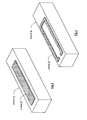
- FIGS 1 and 2 are schematic block diagrams of an embodiment of a liquid micro-electro-mechanical system (MEMS) magnetic component 10 that may be an inductor, a transformer, or a winding of a transformer and that may be used in a wireless communication device.
- a wireless communication device may be a portable computing communication device may be any device that can be carried by a person, can be at least partially powered by a battery, includes a radio transceiver (e.g., radio frequency (RF) and/or millimeter wave (MMW)) and performs one or more software applications.
- the portable computing communication device may be a cellular telephone, a laptop computer, a personal digital assistant, a video game console, a video game player, a personal entertainment unit, a tablet computer, etc.
- the liquid MEMS magnetic component 10 includes a board 12, a channel 14, one or more windings 16, a magnetizing doped droplet 18, and a droplet activating module 20.
- the board 12 may be a printed circuit board (PCB), an integrated circuit (IC) package substrate, or a redistribution layer (RDL) of a PCB or of an IC package substrate and it supports the channel 14 in one or more layers.
- the channel 14 is fabricated in one or more layers of the board 12.
- the channel 14 is embedded into one or more layers of the board 12. Note that the channel 14 may have a variety of shapes.
- the channel 14 may have a square-tubular shape, a cylinder shape, a non-linear square-tubular shape, or a non-linear cylinder shape, where non-linear refers to the axial shape of the channel being something other than a straight line (e.g., a meandering line, an arc, a circle, an ellipse, a polygon, or a portion thereof).
- the channel 14 may have its internal and/or external walls coated with an insulating layer, dielectric layer, a semiconductor layer, and/or a conductive layer.
- the magnetizing-doped droplet 18 is contained in the channel 14 and the one or more windings 16 are proximally positioned to the channel 16 (e.g., on one or more surfaces of the channel).
- the droplet activating module 20 applies a first level of force 22 upon the magnetizing-doped droplet 18 such that the droplet 18 has a first size and/or shape within the channel 14 and/or a first positioning with respect to the one or more windings 16.
- the droplet activating module 20 applies a second level of force 22 upon the magnetizing-doped droplet 18 such that the droplet 18 has a second size and/or shape within the channel 14 and/or a second positioning with respect to the one or more windings 16.
- Modifying the magnetizing-doped droplet 18 with respect to the one or more windings 16 causes a change in an electromagnetic property (e.g., permeability, magnetic coupling, inductance, etc.) of the liquid MEMS magnetic component 10.
- magnetizing-doped droplet 18 is a solution that includes suspending ferrite particles (or magnetic particles) and its shape, size, and/or position changes in the presence of a force 22 (e.g., electric field, magnetic field, compression, actuation, heat, etc.).
- a force 22 e.g., electric field, magnetic field, compression, actuation, heat, etc.
- the droplet 18 is in a contracted shape, which provides a first core property for a liquid MEMS inductor or transformer (i.e., the droplet 18 has the first shape, size, and/or positioning with respect to the winding(s) 16).
- core properties of the magnetic component e.g., changing the relative permeability within a range of an air core to an iron core by modifying the size, shape, and/or position of the droplet 18
- Figure 3 is a schematic block diagram of an embodiment of a liquid MEMS tunable inductor having one or more strip line windings 16 proximally positioned to the channel 14.
- the channel 14 has a square-tubular shape and may be of a size ranging from a few micrometers in height, width, and/or length to several centimeters in in height, width, and/or length.
- the strip line winding 16 is of an electrically conductive material (e.g., copper, gold, aluminum, etc.) and may be deposited on the surface of the channel 14, may be embedded in a side of the channel 14, or may be on an inner surface of the channel 14 separated from the droplet 18 by an insulating layer.
- the inductor may have two or more strip line windings 16 proximal to the channel 14 that are coupled in series and/or in parallel.
- the inductor may include two strip line windings 16 with one winding on one surface of the channel 14 and the other strip line winding on another surface of the channel.
- Figure 4 is a schematic block diagram of an embodiment of a liquid MEMS tunable inductor having one or more coil windings 16 proximally positioned to the channel 14.
- the channel 14 has a square-tubular shape and may be of a size ranging from a few micrometers in height, width, and/or length to several centimeters in in height, width, and/or length.
- the coil winding 16 is of an electrically conductive material (e.g., copper, gold, aluminum, etc.), may include a partial turn, one turn, or many turns, may be deposited on the surface of the channel 14, may be embedded in a side of the channel 14, or may be on an inner surface of the channel 14 separated from the droplet 18 by an insulating layer.
- the inductor may have two or more coil windings 16 proximal to the channel 14 that are coupled in series and/or in parallel.
- the inductor may include two coil windings 16 with one winding on one surface of the channel 14 and the other winding on another surface of the channel.
- Figure 5 is a schematic block diagram of an embodiment of a liquid MEMS tunable inductor having a solenoid winding 16 proximally positioned to the channel 14.
- the channel 14 has a square-tubular shape and may be of a size ranging from a few micrometers in height, width, and/or length to several centimeters in in height, width, and/or length.
- the solenoid winding 16 is of an electrically conductive material (e.g., copper, gold, aluminum, etc.), may include one turn or many turns, may be deposited on the surface of the channel 14, may be embedded in a side of the channel 14, or may be on an inner surface of the channel 14 separated from the droplet 18 by an insulating layer.
- FIG 6 is a schematic block diagram of an embodiment of a liquid MEMS tunable transformer that includes the channel 14, the magnetizing doped droplet 18, a primary winding 16P, and a secondary winding 165.
- Each of the primary and secondary windings 16P and 16S may be a strip winding (as shown in Figure 3 ), a coil winding (as shown in Figure 4 ), or a solenoid winding as will be discussed with reference to Figures 7 and 8 .
- the magnetizing-doped droplet 18 is contained in the channel and is modified by the droplet activating module 20 based on the control signal. By modifying the magnetizing-doped droplet 18 with respect to the primary and secondary windings 16P and 16S changes an electromagnetic property of the liquid MEMS tunable transformer thereby facilitating tuning of the transformer.
- Figure 7 is a schematic block diagram of an embodiment of a liquid MEMS transformer that includes the channel 14, the magnetizing doped droplet 18, a solenoid primary winding 16P, and a solenoid secondary winding 16S.
- the primary and secondary windings 16P and 16S are aligned along the channel 14. While the channel 14 is shown to have a linear square tubular shape, it may, in the alternative, have a non-linear U-shaped square tubular (or cylinder) shape, a non-linear O-shaped, with an air gap, square tubular (or cylinder) shape, etc.
- Figure 8 is a schematic block diagram of another embodiment of a liquid MEMS transformer that includes the channel 14, the magnetizing doped droplet 18, a solenoid primary winding 16P, and a solenoid secondary winding 165.
- the primary and secondary windings 16P and 16S are interwoven along the channel 14. While the channel 14 is shown to have a linear square tubular shape, it may, in the alternative, have a non-linear U-shaped square tubular (or cylinder) shape, a non-linear O-shaped, with an air gap, square tubular (or cylinder) shape, etc.
- FIG 9 is a schematic block diagram of an embodiment of a magnetized doped droplet 18 of a liquid MEMS magnetic component 10.
- the magnetized doped droplet 18 includes a non-magnetic liquid solution (e.g., magnetically and/or electrically inert liquid, gel, oil, etc.) and a plurality of particles 30 suspending in the liquid solution.
- the particles 30 may be ferrite particles and/or permanent magnetic particles. Magnetic particles may be used for a motor stator application and the ferrite particles may be used for inductors and/or transformers.
- the non-magnetic liquid solution has a density that enables suspension of the particles. Further note that the particles may be coated with a material to reduce their individual densities.
- the magnetized doped droplet 18 may be a liquid colloid of the non-magnetic liquid solution and the particles 30 or a hydrocolloid that includes the particles 30 (e.g., ferrite or magnet).
- Figure 10 is a schematic block diagram of an embodiment of a liquid MEMS magnetic component 10 that includes the board 12, the channel 14, one or more windings 16, a plurality of magnetized doped droplets 18-1 18-2, and the droplet activating module 20.
- the magnetizing-doped droplet 18-1 has first magnetic properties (e.g., a first variable relative permeability based on a first concentration, size, material, etc. of the particles in the droplet 18-1) and the second magnetizing-doped droplet 18-2 has second magnetic properties (e.g., a second variable relative permeability based on a second concentration, size, material, etc. of the particles in the droplet 18-2). Since each droplet has a different permeability, they affect the core properties of the magnetic component differently as the force 22 is changed.
- the liquid solution of each droplet may be different such that they react differently to the force.
- the liquid solution of droplet 18-1 has a first density and the liquid solution of droplet 18-2 has a second density such that each reacts differently to an applied force (e.g., compression, heat, actuator, etc.).
- droplets 18-1 and 18-2 are shown to be side-by-side in the channel, they may have a different orientation with respect to one another.
- the droplets 18-1 and 18-2 may be stacked as opposed to side-by-side.
- a barrier physically separates the droplets 18-1 and 18-2 such that the droplets remain side-by-side or stacked.
- the densities of the droplets are different to maintain a physical separation.
- FIGS 11 and 12 are schematic block diagrams of an embodiment of a tunable liquid MEMS magnetic component 10 (e.g., an inductor or a transformer) that includes a channel 14, a droplet 18, a first winding 16, a second winding 17, and a droplet activating module 20.
- the droplet activating module 20 may generate an electric field force, a magnetic field force, a pressure force, an actuator force, or a heat force 22 to move the position of the droplet 18 with respect to the windings 16 and 17.
- the relative permeability of the inductor and/or transformer changes, which changes one or more properties of the inductor and/or transformer (e.g., changes inductance, magnetic coupling, saturation level, etc.).
- one of the windings 16 or 17 is the primary winding and the other is the secondary winding.
- the windings 16 and 17 may be coupled in series or in parallel.
- the second winding 17 may be omitted.
- the windings 16 and 17 may be one or more of a strip line winding, a coil winding, or a solenoid winding.
- the position of the droplet 18 is substantially outside the area in the channel 14 between the winding 16 and 17.
- the permeability of the magnetic component corresponds to the permeability of air or the permeability of a gas that is contained in the channel 14.
- the position of the droplet 18 is substantially within the area in the channel 14 between the windings 16 and 17.
- the permeability of the magnetic component substantially corresponds to the permeability of the droplet 18.
- the position of the droplet 18 may range between its positions of Figures 11 and 12 .
- FIGS 13 and 14 are schematic block diagrams of an embodiment of a tunable liquid MEMS magnetic component 10 (e.g., an inductor or a transformer) that includes a channel 14, a droplet 18, a winding 16, and a droplet activating module 20.
- the droplet activating module 20 generates an electric field force, a magnetic field force, a pressure force, an actuator force, or a heat force 22 that expands or pushes the droplet 18 into the channel 14, which includes a reservoir for holding the droplet 18.
- the droplet 18 As the droplet 18 extends into the channel, it changes the relative permeability of the magnetic component, which changes one or more properties of the magnetic component (e.g., changes inductance, magnetic coupling, saturation level, etc.).
- the winding 16 may be one or more of a strip line winding, a coil winding, or a solenoid winding.
- Figures 15 and 16 are schematic block diagrams of another embodiment of a tunable liquid MEMS magnetic component 10 (e.g., an inductor or a transformer) that includes a channel 14 (which includes a flexible lid 15), a droplet 18, a first winding 16, and a droplet activating module 20.
- the droplet activating module 20 generates a pressure force 22 or an actuator force 22 that presses on the flexible lid 15 of the channel 14, which changes the shape of the droplet 18.
- the relative permeability of the magnetic component which changes one or more properties of the magnetic component (e.g., changes inductance, magnetic coupling, saturation level, etc.).
- the winding 16 may be one or more of a strip line winding, a coil winding, or a solenoid winding.
- Figure 17 is a schematic block diagram of another embodiment of a liquid MEMS magnetic component 40 that includes a board 12, a winding 16, an activating module 42, a droplet reservoir 44, a magnetizing doped solution 46, and a plurality of channels 48.
- the magnetizing-doped solution 46 which is contained in the reservoir 44, includes a colloid of a plurality of ferrite particles and a non-magnetic liquid solution and/or a plurality of ferrite particles suspended in a non-magnetic liquid solution.
- the magnetic component 40 may be a tunable inductor.
- the magnetic component 40 may include a secondary winding to function as a tunable transformer.
- the winding 16 may be one or more of a strip line winding, a coil winding, or a solenoid winding.
- the activating module 42 which may be an actuator or pump, injects the magnetizing-doped solution 46 from the reservoir 44 into a least a portion of one or more channels 48.
- the activating module 42 may inject, or pump, the magnetizing-doped solution 46 into one channel 48 to partially fill it or to fully fill it.
- the activating module 42 may inject, or pump, the magnetizing-doped solution 46 into two channels 48 to partially fill each, to fully fill each, or to partially fill one and fully fill the other.
- the droplet 18 fills one or more channels, it changes the relative permeability of the magnetic component, which changes one or more properties of the magnetic component (e.g., changes inductance, magnetic coupling, saturation level, etc.).
- Figure 18 is a schematic block diagram of an embodiment of a programmable magnetic component 50 that includes a plurality of winding segments 54 and a plurality of liquid MEMS switches 52.
- one or more of the winding segments 54 may be implemented on the board 12 with the liquid MEMS switches 52 and remaining winding segments may be implemented on-chip.
- An example of the liquid MEMS switch 52 is further discussed with reference to Figures 20 and 21 .
- one or more of the liquid MEMS switches 52 is activated to couple one or more of the winding segments 54 in series with one or more other winding segments 54 to produce a winding.
- the winding may be a winding of an inductor or a winding of a transformer.
- One or more of the winding segments 54 may be implemented as previously discussed to provide further programming capabilities or tuning of the magnetic component.
- Figure 19 is a schematic block diagram of another embodiment of a programmable magnetic component 50 that includes a plurality of winding segments 54 and a plurality of liquid MEMS switches 52.
- a programmable magnetic component 50 that includes a plurality of winding segments 54 and a plurality of liquid MEMS switches 52.
- one or more of the winding segments 54 may be implemented on the board 12 with the liquid MEMS switches 52 and remaining winding segments may be implemented on-chip.
- one or more of the liquid MEMS switches 52 is activated to couple one or more of the winding segments 54 in series and/or in parallel with one or more other winding segments 54 to produce a winding.
- the winding elements 54 are coupled together to produce a desired shape, a desired thickness, a desired number of turns, and/or a desired length of a winding.
- the winding may be a winding of an inductor or a winding of a transformer.
- One or more of the winding segments 54 may be implemented as previously discussed to provide further programming capabilities or tuning of the magnetic component.
- the liquid MEMS switches 52 are activated to couple the winding segments 54 in series and/or in parallel to produce two windings.
- the winding elements 54 are coupled together to produce a desired shape, a desired thickness, a desired number of turns, and/or a desired length for each of the windings.
- FIGS 20 and 21 are schematic block diagrams of an embodiment of a liquid MEMS single pole double throw switch 52 for the switch of Figure 18 .
- the switch 52 includes a channel 14, a droplet 60, electrical contacts 62, and a droplet activating module 20.
- the droplet 60 is eclectically conductive (e.g., a liquid metal, a liquid with conductive particles, etc.) and its position changes in the presence of a force 22 (electric and/or magnetic field, pressure, actuator, etc.). With a minimal (or inactive) force 22 applied, the droplet 60 is in a first, which provides a first connection of the switch 52. When a sufficiently large (or active) force 22 is applied, the droplet 60 changes its position, which provides a second connection of the switch 52.
- a force 22 electrical and/or magnetic field, pressure, actuator, etc.
- the switch 52 is a single pole single throw switch, which may be used for the switches of Figure 19 .
- the switch includes two electrical contacts 62. With a minimal (or inactive) force 22 applied, the droplet 60 is not in contact with one of the electrical contacts, as such, the switch 52 is open. When a sufficiently large (or active) force 22 is applied, the droplet is in contact with the electrical contacts, as such, the switch 52 is closed.
- liquid MEMS magnetic component 10 has been discussed as being implemented on a board 16, it could be implemented on an integrated circuit (IC) die.
- a liquid MEMS magnetic component 10 implemented on a board versus an IC die may be tens, hundreds, or thousands of times larger allowing for larger inductors and/or transformers to be implemented on a board versus the IC die.
- IC integrated circuit
- the terms “substantially” and “approximately” provides an industry-accepted tolerance for its corresponding term and/or relativity between items. Such an industry-accepted tolerance ranges from less than one percent to fifty percent and corresponds to, but is not limited to, component values, integrated circuit process variations, temperature variations, rise and fall times, and/or thermal noise. Such relativity between items ranges from a difference of a few percent to magnitude differences.
- the term(s) "operably coupled to”, “coupled to”, and/or “coupling” includes direct coupling between items and/or indirect coupling between items via an intervening item (e.g., an item includes, but is not limited to, a component, an element, a circuit, and/or a module) where, for indirect coupling, the intervening item does not modify the information of a signal but may adjust its current level, voltage level, and/or power level.
- inferred coupling i.e., where one element is coupled to another element by inference
- the term "operable to” or “operably coupled to” indicates that an item includes one or more of power connections, input(s), output(s), etc., to perform, when activated, one or more its corresponding functions and may further include inferred coupling to one or more other items.
- the term “associated with”, includes direct and/or indirect coupling of separate items and/or one item being embedded within another item.
- the term “compares favorably”, indicates that a comparison between two or more items, signals, etc., provides a desired relationship. For example, when the desired relationship is that signal 1 has a greater magnitude than signal 2, a favorable comparison may be achieved when the magnitude of signal 1 is greater than that of signal 2 or when the magnitude of signal 2 is less than that of signal 1.
- processing module may be a single processing device or a plurality of processing devices.
- a processing device may be a microprocessor, micro-controller, digital signal processor, microcomputer, central processing unit, field programmable gate array, programmable logic device, state machine, logic circuitry, analog circuitry, digital circuitry, and/or any device that manipulates signals (analog and/or digital) based on hard coding of the circuitry and/or operational instructions.
- the processing module, module, processing circuit, and/or processing unit may be, or further include, memory and/or an integrated memory element, which may be a single memory device, a plurality of memory devices, and/or embedded circuitry of another processing module, module, processing circuit, and/or processing unit.
- a memory device may be a read-only memory, random access memory, volatile memory, non-volatile memory, static memory, dynamic memory, flash memory, cache memory, and/or any device that stores digital information.
- processing module, module, processing circuit, and/or processing unit includes more than one processing device, the processing devices may be centrally located (e.g., directly coupled together via a wired and/or wireless bus structure) or may be distributedly located (e.g., cloud computing via indirect coupling via a local area network and/or a wide area network). Further note that if the processing module, module, processing circuit, and/or processing unit implements one or more of its functions via a state machine, analog circuitry, digital circuitry, and/or logic circuitry, the memory and/or memory element storing the corresponding operational instructions may be embedded within, or external to, the circuitry comprising the state machine, analog circuitry, digital circuitry, and/or logic circuitry.
- the memory element may store, and the processing module, module, processing circuit, and/or processing unit executes, hard coded and/or operational instructions corresponding to at least some of the steps and/or functions illustrated in one or more of the Figures.
- Such a memory device or memory element can be included in an article of manufacture.
- the present invention may have also been described, at least in part, in terms of one or more embodiments.
- An embodiment of the present invention is used herein to illustrate the present invention, an aspect thereof, a feature thereof, a concept thereof, and/or an example thereof.
- a physical embodiment of an apparatus, an article of manufacture, a machine, and/or of a process that embodies the present invention may include one or more of the aspects, features, concepts, examples, etc. described with reference to one or more of the embodiments discussed herein.
- the embodiments may incorporate the same or similarly named functions, steps, modules, etc. that may use the same or different reference numbers and, as such, the functions, steps, modules, etc. may be the same or similar functions, steps, modules, etc. or different ones.
- transistors in the above described figure(s) is/are shown as field effect transistors (FETs), as one of ordinary skill in the art will appreciate, the transistors may be implemented using any type of transistor structure including, but not limited to, bipolar, metal oxide semiconductor field effect transistors (MOSFET), N-well transistors, P-well transistors, enhancement mode, depletion mode, and zero voltage threshold (VT) transistors.
- FETs field effect transistors
- MOSFET metal oxide semiconductor field effect transistors
- N-well transistors N-well transistors
- P-well transistors P-well transistors
- enhancement mode enhancement mode
- depletion mode depletion mode
- VT zero voltage threshold
- signals to, from, and/or between elements in a figure of any of the figures presented herein may be analog or digital, continuous time or discrete time, and single-ended or differential.
- signals to, from, and/or between elements in a figure of any of the figures presented herein may be analog or digital, continuous time or discrete time, and single-ended or differential.
- a signal path is shown as a single-ended path, it also represents a differential signal path.
- a signal path is shown as a differential path, it also represents a single-ended signal path.
- module is used in the description of the various embodiments of the present invention.
- a module includes a processing module, a functional block, hardware, and/or software stored on memory for performing one or more functions as may be described herein. Note that, if the module is implemented via hardware, the hardware may operate independently and/or in conjunction software and/or firmware.
- a module may contain one or more sub-modules, each of which may be one or more modules.
Landscapes
- Engineering & Computer Science (AREA)
- Power Engineering (AREA)
- Micromachines (AREA)
Abstract
Description
- The present U.S. Utility Patent Application claims priority pursuant to 35 U.S.C. § 119(e) to
U.S. Provisional Application No. 61/699,183 - This invention relates generally to radio communications and more particularly to liquid MEMS magnetic components that may be used in wireless communication devices.
- Radio frequency (RF) communication devices are known to facilitate wireless communications in one or more frequency bands in accordance with one or more wireless communication protocols or standards. To accommodate multiple communication protocols, or standards, an RF communication device includes multiple versions (one for each protocol) of each section of the RF communication device (e.g., baseband processing, RF receiver, RF transmitter, antenna interface) and/or includes programmable sections. For example, an RF communication device may include a programmable baseband section, multiple RF receiver sections, multiple RF transmitter sections, and a programmable antenna interface.
- To provide at least some of the programmable capabilities of a programmable section of an RF communication device, the section includes one or more programmable circuits, wherein the programmability is achieved via a switch-based bank of circuit elements (e.g., capacitors, inductors, resistors). For instance, selecting various combinations of a switch-based bank of capacitors and switch-based bank of inductors yields various resonant tank circuits that can be used in filters, as loads in amplifiers, etc. A recent advance in RF technology is to use integrated circuit (IC) micro-electro-mechanical system (MEMS) switches to provide the switches of a switch-based bank of circuit elements.
- Issues with IC MEMS switches include minimal contact areas (which creates heat spots), bouncing of electrical contact (which limits use to cold switching), and a limited life cycle. In response to these issues, more recent advances in RF technology employ IC implemented liquid RF MEMS switches (which may also be referred to as electrochemical wetting switches). As IC fabrication technologies continue to evolve and reduce the size of IC dies and components fabricated thereon, IC implemented liquid RF MEMS switches may have limited applications.
- According to an aspect, a liquid micro-electro-mechanical system (MEMS) magnetic component comprises:
- a board;
- a channel in one or more layers of the board;
- one or more windings proximally positioned to the channel;
- a magnetizing-doped droplet contained in the channel; and
- a droplet activating module operable, based on the control signal, to modify the magnetizing-doped droplet with respect to the one or more windings thereby changing an electromagnetic property of the liquid MEMS magnetic component.
- Advantageously, the liquid MEMS magnetic component further comprises:
- the one or more windings including a winding such that the liquid MEMS magnetic component is a tunable inductor.
- Advantageously, the liquid MEMS magnetic component further comprises:
- the one or more windings including a primary winding and a secondary winding such that the liquid MEMS magnetic component is a tunable transformer.
- Advantageously, the magnetizing-doped droplet comprises:
- a plurality of ferrite particles suspended in a non- magnetic liquid solution.
- Advantageously, the magnetizing-doped droplet comprises:
- a plurality of permanent magnetics particles suspended in a non- magnetic liquid solution.
- Advantageously, the liquid MEMS magnetic component further comprises:
- a second magnetizing-doped droplet, wherein the magnetizing-doped droplet has first magnetic properties and the second magnetizing-doped droplet has second magnetic properties.
- Advantageously, the channel comprises one of:
- a square-tubular shape;
- a cylinder shape;
- a non-linear square-tubular shape; and
- a non-linear cylinder shape.
- Advantageously, the droplet activating module comprises at least one of:
- an actuator;
- an electric field source;
- a magnetic field source;
- a heat source;
- a compression source; and
- an expansion source.
- Advantageously, the liquid MEMS magnetic component further comprises:
- an activation droplet that provides a force on the magnetizing-doped droplet such that the magnetizing-doped droplet moves within the channel, wherein the activation droplet is responsive to at least one of:
- an electric field from the electric field source;
- a magnetic field from the magnetic field source;
- heat from the heat source;
- compression from the compression source; and
- expansion from the expansion source.
- Advantageously, the board comprises at least one of:
- a printed circuit board (PCB);
- an integrated circuit (IC) package substrate;
- a redistribution layer (RDL) of a PCB or of an IC package substrate.
- According to an aspect, a liquid micro-electro-mechanical system (MEMS) magnetic component comprises:
- a board;
- a plurality of channels in multiple layers of the board;
- one or more windings proximally positioned to the plurality of channels; and
- an activating module operable to inject a magnetizing-doped solution into a least a portion of one or more channels of the plurality of channels to change an electromagnetic property of the liquid MEMS magnetic component.
- Advantageously, the liquid MEMS magnetic component further comprises:
- the one or more windings including a winding such that the liquid MEMS magnetic component is a tunable inductor.
- Advantageously, the liquid MEMS magnetic component further comprises:
- the one or more windings including a primary winding and a secondary winding such that the liquid MEMS magnetic component is a tunable transformer.
- Advantageously, the magnetizing-doped solution comprises:
- a plurality of ferrite particles suspended in a non- magnetic liquid solution.
- Advantageously, the activating module comprises one or more actuators.
- According to an aspect, a programmable magnetic component comprises:
- a plurality of winding segments on substrate;
- a plurality of liquid micro-electro-mechanical system (MEMS) switches, wherein a liquid MEMS switch of the plurality of liquid MEMS switches includes:
- a board;
- a channel in one or more layers of the board;
- electric contacts proximal to the channel;
- a conductive droplet contained in the channel; and
- a droplet activating module operable:
- in a first state, to cause the conductive droplet to electrically connect to the electric contacts; and
- in a second state, to cause the conductive droplet to not be electrically connected to at least one of the electrical contacts;
- a control module operable to place one or more of the plurality of liquid MEMS switches in the first state to couple two or more of the plurality of winding segments together to form a winding of the programmable magnetic component.
- Advantageously, the programmable magnetic component further comprises:
- a second channel in another one or more layers of the board, wherein the plurality of winding segments are proximally positioned to the second channel;
- a magnetizing-doped droplet contained in the second channel; and
- a droplet activating module operable, based on the control signal from the control module, to modify the magnetizing-doped droplet with respect to the plurality of winding segments thereby changing an electromagnetic property of the programmable magnetic component.
- Advantageously, the programmable magnetic component further comprises:
- a plurality of channels in multiple layers of the board, wherein the plurality of winding segments are proximally positioned to the plurality of channels; and
- an activating module operable to inject a magnetizing-doped solution into a least a portion of one or more channels of the plurality of channels to change an electromagnetic property of the programmable magnetic component.
- Advantageously, the programmable magnetic component further comprises:
- the board including the substrate.
- Advantageously, the programmable magnetic component further comprises:
- the substrate including an integrated circuit die, which further supports the control module.
-
-
Figures 1 and 2 are schematic block diagrams of an embodiment of a liquid MEMS magnetic component in accordance with the present invention; -
Figure 3 is a schematic block diagram of an embodiment of a liquid MEMS inductor having one or more strip line windings in accordance with the present invention; -
Figure 4 is a schematic block diagram of an embodiment of a liquid MEMS inductor having one or more coil windings in accordance with the present invention; -
Figure 5 is a schematic block diagram of an embodiment of a liquid MEMS inductor having a solenoid winding in accordance with the present invention; -
Figure 6 is a schematic block diagram of an embodiment of a liquid MEMS transformer having a primary winding and a secondary winding in accordance with the present invention; -
Figure 7 is a schematic block diagram of an embodiment of a liquid MEMS transformer having a solenoid primary winding and a solenoid secondary winding in accordance with the present invention; -
Figure 8 is a schematic block diagram of another embodiment of a liquid MEMS transformer having a solenoid primary winding and a solenoid secondary winding in accordance with the present invention; -
Figure 9 is a schematic block diagram of an embodiment of a magnetized doped droplet of a liquid MEMS magnetic component in accordance with the present invention; -
Figure 10 is a schematic block diagram of an embodiment of a liquid MEMS magnetic component having multiple droplets in accordance with the present invention; -
Figures 11 and 12 are schematic block diagrams of another embodiment of a liquid MEMS magnetic component in accordance with the present invention; -
Figures 13 and 14 are schematic block diagrams of an embodiment of a droplet activating module of a liquid MEMS magnetic component in accordance with the present invention; -
Figures 15 and 16 are schematic block diagrams of another embodiment of a droplet activating module of a liquid MEMS magnetic component in accordance with the present invention; -
Figure 17 is a schematic block diagram of another embodiment of a liquid MEMS magnetic component in accordance with the present invention; -
Figure 18 is a schematic block diagram of an embodiment of a programmable magnetic component including liquid MEMS switches in accordance with the present invention; -
Figure 19 is a schematic block diagram of another embodiment of a programmable magnetic component including liquid MEMS switches in accordance with the present invention; and -
Figures 20 and 21 are schematic block diagrams of an embodiment of a liquid MEMS switch in accordance with the present invention. -
Figures 1 and 2 are schematic block diagrams of an embodiment of a liquid micro-electro-mechanical system (MEMS)magnetic component 10 that may be an inductor, a transformer, or a winding of a transformer and that may be used in a wireless communication device. A wireless communication device may be a portable computing communication device may be any device that can be carried by a person, can be at least partially powered by a battery, includes a radio transceiver (e.g., radio frequency (RF) and/or millimeter wave (MMW)) and performs one or more software applications. For example, the portable computing communication device may be a cellular telephone, a laptop computer, a personal digital assistant, a video game console, a video game player, a personal entertainment unit, a tablet computer, etc. - As shown, the liquid MEMS
magnetic component 10 includes aboard 12, achannel 14, one ormore windings 16, a magnetizing dopeddroplet 18, and adroplet activating module 20. Theboard 12 may be a printed circuit board (PCB), an integrated circuit (IC) package substrate, or a redistribution layer (RDL) of a PCB or of an IC package substrate and it supports thechannel 14 in one or more layers. For example, thechannel 14 is fabricated in one or more layers of theboard 12. As another example, thechannel 14 is embedded into one or more layers of theboard 12. Note that thechannel 14 may have a variety of shapes. For example, thechannel 14 may have a square-tubular shape, a cylinder shape, a non-linear square-tubular shape, or a non-linear cylinder shape, where non-linear refers to the axial shape of the channel being something other than a straight line (e.g., a meandering line, an arc, a circle, an ellipse, a polygon, or a portion thereof). In addition, thechannel 14 may have its internal and/or external walls coated with an insulating layer, dielectric layer, a semiconductor layer, and/or a conductive layer. - The magnetizing-doped
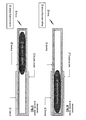
droplet 18 is contained in thechannel 14 and the one ormore windings 16 are proximally positioned to the channel 16 (e.g., on one or more surfaces of the channel). As shown inFigure 1 , thedroplet activating module 20 applies a first level offorce 22 upon the magnetizing-dopeddroplet 18 such that thedroplet 18 has a first size and/or shape within thechannel 14 and/or a first positioning with respect to the one ormore windings 16. As shown inFigure 2 , thedroplet activating module 20 applies a second level offorce 22 upon the magnetizing-dopeddroplet 18 such that thedroplet 18 has a second size and/or shape within thechannel 14 and/or a second positioning with respect to the one ormore windings 16. Modifying the magnetizing-dopeddroplet 18 with respect to the one ormore windings 16 causes a change in an electromagnetic property (e.g., permeability, magnetic coupling, inductance, etc.) of the liquid MEMSmagnetic component 10. - As an example, magnetizing-doped
droplet 18 is a solution that includes suspending ferrite particles (or magnetic particles) and its shape, size, and/or position changes in the presence of a force 22 (e.g., electric field, magnetic field, compression, actuation, heat, etc.). For example, with a minimal (or inactive) force applied, thedroplet 18 is in a contracted shape, which provides a first core property for a liquid MEMS inductor or transformer (i.e., thedroplet 18 has the first shape, size, and/or positioning with respect to the winding(s) 16). When a sufficiently large (or active)force 22 is applied, the shape, size, and/or position of thedroplet 18 change, which changes the core properties of the inductor or transformer (e.g., changes an electromagnetic property of the liquid MEMS magnetic component). Note that for a solenoid inductor, inductance is L = µ0µrN2(A/l), where L is inductance, µ0 is the magnetic constant, µr is the relative permeability of the material within the solenoid, N is the number of turns, A is the cross-sectional area of the solenoid, and 1 is the length of the winding. As such, by changing the core properties of the magnetic component (e.g., changing the relative permeability within a range of an air core to an iron core by modifying the size, shape, and/or position of the droplet 18), its inductance is changed. -
Figure 3 is a schematic block diagram of an embodiment of a liquid MEMS tunable inductor having one or morestrip line windings 16 proximally positioned to thechannel 14. In this instance, thechannel 14 has a square-tubular shape and may be of a size ranging from a few micrometers in height, width, and/or length to several centimeters in in height, width, and/or length. The strip line winding 16 is of an electrically conductive material (e.g., copper, gold, aluminum, etc.) and may be deposited on the surface of thechannel 14, may be embedded in a side of thechannel 14, or may be on an inner surface of thechannel 14 separated from thedroplet 18 by an insulating layer. Note that the inductor may have two or morestrip line windings 16 proximal to thechannel 14 that are coupled in series and/or in parallel. For example, the inductor may include twostrip line windings 16 with one winding on one surface of thechannel 14 and the other strip line winding on another surface of the channel. -
Figure 4 is a schematic block diagram of an embodiment of a liquid MEMS tunable inductor having one ormore coil windings 16 proximally positioned to thechannel 14. In this instance, thechannel 14 has a square-tubular shape and may be of a size ranging from a few micrometers in height, width, and/or length to several centimeters in in height, width, and/or length. The coil winding 16 is of an electrically conductive material (e.g., copper, gold, aluminum, etc.), may include a partial turn, one turn, or many turns, may be deposited on the surface of thechannel 14, may be embedded in a side of thechannel 14, or may be on an inner surface of thechannel 14 separated from thedroplet 18 by an insulating layer. Note that the inductor may have two ormore coil windings 16 proximal to thechannel 14 that are coupled in series and/or in parallel. For example, the inductor may include twocoil windings 16 with one winding on one surface of thechannel 14 and the other winding on another surface of the channel. -
Figure 5 is a schematic block diagram of an embodiment of a liquid MEMS tunable inductor having a solenoid winding 16 proximally positioned to thechannel 14. In this instance, thechannel 14 has a square-tubular shape and may be of a size ranging from a few micrometers in height, width, and/or length to several centimeters in in height, width, and/or length. The solenoid winding 16 is of an electrically conductive material (e.g., copper, gold, aluminum, etc.), may include one turn or many turns, may be deposited on the surface of thechannel 14, may be embedded in a side of thechannel 14, or may be on an inner surface of thechannel 14 separated from thedroplet 18 by an insulating layer. -
Figure 6 is a schematic block diagram of an embodiment of a liquid MEMS tunable transformer that includes thechannel 14, the magnetizing dopeddroplet 18, a primary winding 16P, and a secondary winding 165. Each of the primary andsecondary windings Figure 3 ), a coil winding (as shown inFigure 4 ), or a solenoid winding as will be discussed with reference toFigures 7 and 8 . In general, the magnetizing-dopeddroplet 18 is contained in the channel and is modified by thedroplet activating module 20 based on the control signal. By modifying the magnetizing-dopeddroplet 18 with respect to the primary andsecondary windings -
Figure 7 is a schematic block diagram of an embodiment of a liquid MEMS transformer that includes thechannel 14, the magnetizing dopeddroplet 18, a solenoid primary winding 16P, and a solenoid secondary winding 16S. In this embodiment, the primary andsecondary windings channel 14. While thechannel 14 is shown to have a linear square tubular shape, it may, in the alternative, have a non-linear U-shaped square tubular (or cylinder) shape, a non-linear O-shaped, with an air gap, square tubular (or cylinder) shape, etc. -
Figure 8 is a schematic block diagram of another embodiment of a liquid MEMS transformer that includes thechannel 14, the magnetizing dopeddroplet 18, a solenoid primary winding 16P, and a solenoid secondary winding 165. In this embodiment, the primary andsecondary windings channel 14. While thechannel 14 is shown to have a linear square tubular shape, it may, in the alternative, have a non-linear U-shaped square tubular (or cylinder) shape, a non-linear O-shaped, with an air gap, square tubular (or cylinder) shape, etc. -
Figure 9 is a schematic block diagram of an embodiment of a magnetized dopeddroplet 18 of a liquid MEMSmagnetic component 10. The magnetized dopeddroplet 18 includes a non-magnetic liquid solution (e.g., magnetically and/or electrically inert liquid, gel, oil, etc.) and a plurality of particles 30 suspending in the liquid solution. The particles 30 may be ferrite particles and/or permanent magnetic particles. Magnetic particles may be used for a motor stator application and the ferrite particles may be used for inductors and/or transformers. Note that the non-magnetic liquid solution has a density that enables suspension of the particles. Further note that the particles may be coated with a material to reduce their individual densities. Alternatively, the magnetized dopeddroplet 18 may be a liquid colloid of the non-magnetic liquid solution and the particles 30 or a hydrocolloid that includes the particles 30 (e.g., ferrite or magnet). -
Figure 10 is a schematic block diagram of an embodiment of a liquid MEMSmagnetic component 10 that includes theboard 12, thechannel 14, one ormore windings 16, a plurality of magnetized doped droplets 18-1 18-2, and thedroplet activating module 20. In this embodiment, the magnetizing-doped droplet 18-1 has first magnetic properties (e.g., a first variable relative permeability based on a first concentration, size, material, etc. of the particles in the droplet 18-1) and the second magnetizing-doped droplet 18-2 has second magnetic properties (e.g., a second variable relative permeability based on a second concentration, size, material, etc. of the particles in the droplet 18-2). Since each droplet has a different permeability, they affect the core properties of the magnetic component differently as theforce 22 is changed. - To further enhance the difference between the droplets, the liquid solution of each droplet may be different such that they react differently to the force. For example, the liquid solution of droplet 18-1 has a first density and the liquid solution of droplet 18-2 has a second density such that each reacts differently to an applied force (e.g., compression, heat, actuator, etc.).
- While the droplets 18-1 and 18-2 are shown to be side-by-side in the channel, they may have a different orientation with respect to one another. For example, the droplets 18-1 and 18-2 may be stacked as opposed to side-by-side. As another example, a barrier physically separates the droplets 18-1 and 18-2 such that the droplets remain side-by-side or stacked. As yet another example, the densities of the droplets are different to maintain a physical separation.
-
Figures 11 and 12 are schematic block diagrams of an embodiment of a tunable liquid MEMS magnetic component 10 (e.g., an inductor or a transformer) that includes achannel 14, adroplet 18, a first winding 16, a second winding 17, and adroplet activating module 20. Thedroplet activating module 20 may generate an electric field force, a magnetic field force, a pressure force, an actuator force, or aheat force 22 to move the position of thedroplet 18 with respect to thewindings droplet 18 changes with respect to thewindings windings windings windings - As shown in
Figure 11 , the position of thedroplet 18 is substantially outside the area in thechannel 14 between the winding 16 and 17. In this instance, the permeability of the magnetic component corresponds to the permeability of air or the permeability of a gas that is contained in thechannel 14. As shown in theFigure 12 , the position of thedroplet 18 is substantially within the area in thechannel 14 between thewindings droplet 18. As theforce 22 is varied, the position of thedroplet 18 may range between its positions ofFigures 11 and 12 . -
Figures 13 and 14 are schematic block diagrams of an embodiment of a tunable liquid MEMS magnetic component 10 (e.g., an inductor or a transformer) that includes achannel 14, adroplet 18, a winding 16, and adroplet activating module 20. Thedroplet activating module 20 generates an electric field force, a magnetic field force, a pressure force, an actuator force, or aheat force 22 that expands or pushes thedroplet 18 into thechannel 14, which includes a reservoir for holding thedroplet 18. As thedroplet 18 extends into the channel, it changes the relative permeability of the magnetic component, which changes one or more properties of the magnetic component (e.g., changes inductance, magnetic coupling, saturation level, etc.). Note that, for a transformer, another winding would be present. Further note the winding 16 may be one or more of a strip line winding, a coil winding, or a solenoid winding. -
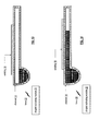
Figures 15 and 16 are schematic block diagrams of another embodiment of a tunable liquid MEMS magnetic component 10 (e.g., an inductor or a transformer) that includes a channel 14 (which includes a flexible lid 15), adroplet 18, a first winding 16, and adroplet activating module 20. Thedroplet activating module 20 generates apressure force 22 or anactuator force 22 that presses on theflexible lid 15 of thechannel 14, which changes the shape of thedroplet 18. As thedroplet 18 changes shape in response to the force, the relative permeability of the magnetic component, which changes one or more properties of the magnetic component (e.g., changes inductance, magnetic coupling, saturation level, etc.). Note that, for a transformer, another winding would be present. Further note the winding 16 may be one or more of a strip line winding, a coil winding, or a solenoid winding. -
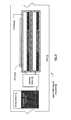
Figure 17 is a schematic block diagram of another embodiment of a liquid MEMSmagnetic component 40 that includes aboard 12, a winding 16, an activatingmodule 42, adroplet reservoir 44, a magnetizing dopedsolution 46, and a plurality ofchannels 48. The magnetizing-dopedsolution 46, which is contained in thereservoir 44, includes a colloid of a plurality of ferrite particles and a non-magnetic liquid solution and/or a plurality of ferrite particles suspended in a non-magnetic liquid solution. Note that themagnetic component 40 may be a tunable inductor. Further note that themagnetic component 40 may include a secondary winding to function as a tunable transformer. Still further note that the winding 16 may be one or more of a strip line winding, a coil winding, or a solenoid winding. - In an example of operation, the activating
module 42, which may be an actuator or pump, injects the magnetizing-dopedsolution 46 from thereservoir 44 into a least a portion of one ormore channels 48. For example, the activatingmodule 42 may inject, or pump, the magnetizing-dopedsolution 46 into onechannel 48 to partially fill it or to fully fill it. As another example, the activatingmodule 42 may inject, or pump, the magnetizing-dopedsolution 46 into twochannels 48 to partially fill each, to fully fill each, or to partially fill one and fully fill the other. As thedroplet 18 fills one or more channels, it changes the relative permeability of the magnetic component, which changes one or more properties of the magnetic component (e.g., changes inductance, magnetic coupling, saturation level, etc.). -
Figure 18 is a schematic block diagram of an embodiment of a programmablemagnetic component 50 that includes a plurality of windingsegments 54 and a plurality of liquid MEMS switches 52. In an implementation, one or more of the windingsegments 54 may be implemented on theboard 12 with the liquid MEMS switches 52 and remaining winding segments may be implemented on-chip. An example of theliquid MEMS switch 52 is further discussed with reference toFigures 20 and 21 . - In an example of operation, one or more of the liquid MEMS switches 52 is activated to couple one or more of the winding
segments 54 in series with one or more other windingsegments 54 to produce a winding. The winding may be a winding of an inductor or a winding of a transformer. One or more of the windingsegments 54 may be implemented as previously discussed to provide further programming capabilities or tuning of the magnetic component. -
Figure 19 is a schematic block diagram of another embodiment of a programmablemagnetic component 50 that includes a plurality of windingsegments 54 and a plurality of liquid MEMS switches 52. In an implementation, one or more of the windingsegments 54 may be implemented on theboard 12 with the liquid MEMS switches 52 and remaining winding segments may be implemented on-chip. - In an example of operation, one or more of the liquid MEMS switches 52 is activated to couple one or more of the winding
segments 54 in series and/or in parallel with one or more other windingsegments 54 to produce a winding. In this manner, the windingelements 54 are coupled together to produce a desired shape, a desired thickness, a desired number of turns, and/or a desired length of a winding. The winding may be a winding of an inductor or a winding of a transformer. One or more of the windingsegments 54 may be implemented as previously discussed to provide further programming capabilities or tuning of the magnetic component. - In another example of operation, the liquid MEMS switches 52 are activated to couple the winding
segments 54 in series and/or in parallel to produce two windings. In this manner, the windingelements 54 are coupled together to produce a desired shape, a desired thickness, a desired number of turns, and/or a desired length for each of the windings. -
Figures 20 and 21 are schematic block diagrams of an embodiment of a liquid MEMS single poledouble throw switch 52 for the switch ofFigure 18 . Theswitch 52 includes achannel 14, adroplet 60,electrical contacts 62, and adroplet activating module 20. Thedroplet 60 is eclectically conductive (e.g., a liquid metal, a liquid with conductive particles, etc.) and its position changes in the presence of a force 22 (electric and/or magnetic field, pressure, actuator, etc.). With a minimal (or inactive)force 22 applied, thedroplet 60 is in a first, which provides a first connection of theswitch 52. When a sufficiently large (or active)force 22 is applied, thedroplet 60 changes its position, which provides a second connection of theswitch 52. - In an alternate embodiment, the
switch 52 is a single pole single throw switch, which may be used for the switches ofFigure 19 . In this embodiment, the switch includes twoelectrical contacts 62. With a minimal (or inactive)force 22 applied, thedroplet 60 is not in contact with one of the electrical contacts, as such, theswitch 52 is open. When a sufficiently large (or active)force 22 is applied, the droplet is in contact with the electrical contacts, as such, theswitch 52 is closed. - While the liquid MEMS
magnetic component 10 has been discussed as being implemented on aboard 16, it could be implemented on an integrated circuit (IC) die. A liquid MEMSmagnetic component 10 implemented on a board versus an IC die may be tens, hundreds, or thousands of times larger allowing for larger inductors and/or transformers to be implemented on a board versus the IC die. Nevertheless, there may certain applications where implementing the liquid MEMS magnetic component on one or more IC dies is more desirable than implementing the magnetic component on a board. In other applications, it may be desirable to implement a primary winding of transformer on a board and one or more secondary windings on one or more IC dies. - As may be used herein, the terms "substantially" and "approximately" provides an industry-accepted tolerance for its corresponding term and/or relativity between items. Such an industry-accepted tolerance ranges from less than one percent to fifty percent and corresponds to, but is not limited to, component values, integrated circuit process variations, temperature variations, rise and fall times, and/or thermal noise. Such relativity between items ranges from a difference of a few percent to magnitude differences. As may also be used herein, the term(s) "operably coupled to", "coupled to", and/or "coupling" includes direct coupling between items and/or indirect coupling between items via an intervening item (e.g., an item includes, but is not limited to, a component, an element, a circuit, and/or a module) where, for indirect coupling, the intervening item does not modify the information of a signal but may adjust its current level, voltage level, and/or power level. As may further be used herein, inferred coupling (i.e., where one element is coupled to another element by inference) includes direct and indirect coupling between two items in the same manner as "coupled to". As may even further be used herein, the term "operable to" or "operably coupled to" indicates that an item includes one or more of power connections, input(s), output(s), etc., to perform, when activated, one or more its corresponding functions and may further include inferred coupling to one or more other items. As may still further be used herein, the term "associated with", includes direct and/or indirect coupling of separate items and/or one item being embedded within another item. As may be used herein, the term "compares favorably", indicates that a comparison between two or more items, signals, etc., provides a desired relationship. For example, when the desired relationship is that signal 1 has a greater magnitude than signal 2, a favorable comparison may be achieved when the magnitude of signal 1 is greater than that of signal 2 or when the magnitude of signal 2 is less than that of signal 1.
- As may also be used herein, the terms "processing module", "processing circuit", and/or "processing unit" may be a single processing device or a plurality of processing devices. Such a processing device may be a microprocessor, micro-controller, digital signal processor, microcomputer, central processing unit, field programmable gate array, programmable logic device, state machine, logic circuitry, analog circuitry, digital circuitry, and/or any device that manipulates signals (analog and/or digital) based on hard coding of the circuitry and/or operational instructions. The processing module, module, processing circuit, and/or processing unit may be, or further include, memory and/or an integrated memory element, which may be a single memory device, a plurality of memory devices, and/or embedded circuitry of another processing module, module, processing circuit, and/or processing unit. Such a memory device may be a read-only memory, random access memory, volatile memory, non-volatile memory, static memory, dynamic memory, flash memory, cache memory, and/or any device that stores digital information. Note that if the processing module, module, processing circuit, and/or processing unit includes more than one processing device, the processing devices may be centrally located (e.g., directly coupled together via a wired and/or wireless bus structure) or may be distributedly located (e.g., cloud computing via indirect coupling via a local area network and/or a wide area network). Further note that if the processing module, module, processing circuit, and/or processing unit implements one or more of its functions via a state machine, analog circuitry, digital circuitry, and/or logic circuitry, the memory and/or memory element storing the corresponding operational instructions may be embedded within, or external to, the circuitry comprising the state machine, analog circuitry, digital circuitry, and/or logic circuitry. Still further note that, the memory element may store, and the processing module, module, processing circuit, and/or processing unit executes, hard coded and/or operational instructions corresponding to at least some of the steps and/or functions illustrated in one or more of the Figures. Such a memory device or memory element can be included in an article of manufacture.
- The present invention has been described above with the aid of method steps illustrating the performance of specified functions and relationships thereof. The boundaries and sequence of these functional building blocks and method steps have been arbitrarily defined herein for convenience of description. Alternate boundaries and sequences can be defined so long as the specified functions and relationships are appropriately performed. Any such alternate boundaries or sequences are thus within the scope and spirit of the claimed invention. Further, the boundaries of these functional building blocks have been arbitrarily defined for convenience of description. Alternate boundaries could be defined as long as the certain significant functions are appropriately performed. Similarly, flow diagram blocks may also have been arbitrarily defined herein to illustrate certain significant functionality. To the extent used, the flow diagram block boundaries and sequence could have been defined otherwise and still perform the certain significant functionality. Such alternate definitions of both functional building blocks and flow diagram blocks and sequences are thus within the scope and spirit of the claimed invention. One of average skill in the art will also recognize that the functional building blocks, and other illustrative blocks, modules and components herein, can be implemented as illustrated or by discrete components, application specific integrated circuits, processors executing appropriate software and the like or any combination thereof.
- The present invention may have also been described, at least in part, in terms of one or more embodiments. An embodiment of the present invention is used herein to illustrate the present invention, an aspect thereof, a feature thereof, a concept thereof, and/or an example thereof. A physical embodiment of an apparatus, an article of manufacture, a machine, and/or of a process that embodies the present invention may include one or more of the aspects, features, concepts, examples, etc. described with reference to one or more of the embodiments discussed herein. Further, from figure to figure, the embodiments may incorporate the same or similarly named functions, steps, modules, etc. that may use the same or different reference numbers and, as such, the functions, steps, modules, etc. may be the same or similar functions, steps, modules, etc. or different ones.
- While the transistors in the above described figure(s) is/are shown as field effect transistors (FETs), as one of ordinary skill in the art will appreciate, the transistors may be implemented using any type of transistor structure including, but not limited to, bipolar, metal oxide semiconductor field effect transistors (MOSFET), N-well transistors, P-well transistors, enhancement mode, depletion mode, and zero voltage threshold (VT) transistors.
- Unless specifically stated to the contra, signals to, from, and/or between elements in a figure of any of the figures presented herein may be analog or digital, continuous time or discrete time, and single-ended or differential. For instance, if a signal path is shown as a single-ended path, it also represents a differential signal path. Similarly, if a signal path is shown as a differential path, it also represents a single-ended signal path. While one or more particular architectures are described herein, other architectures can likewise be implemented that use one or more data buses not expressly shown, direct connectivity between elements, and/or indirect coupling between other elements as recognized by one of average skill in the art.
- The term "module" is used in the description of the various embodiments of the present invention. A module includes a processing module, a functional block, hardware, and/or software stored on memory for performing one or more functions as may be described herein. Note that, if the module is implemented via hardware, the hardware may operate independently and/or in conjunction software and/or firmware. As used herein, a module may contain one or more sub-modules, each of which may be one or more modules.
- While particular combinations of various functions and features of the present invention have been expressly described herein, other combinations of these features and functions are likewise possible. The present invention is not limited by the particular examples disclosed herein and expressly incorporates these other combinations.
Claims (15)
- A liquid micro-electro-mechanical system (MEMS) magnetic component comprises:a board;a channel in one or more layers of the board;one or more windings proximally positioned to the channel;a magnetizing-doped droplet contained in the channel; anda droplet activating module operable, based on the control signal, to modify the magnetizing-doped droplet with respect to the one or more windings thereby changing an electromagnetic property of the liquid MEMS magnetic component.
- The liquid MEMS magnetic component of claim 1 further comprises:the one or more windings including a winding such that the liquid MEMS magnetic component is a tunable inductor.
- The liquid MEMS magnetic component of claim 1 or 2 further comprises:the one or more windings including a primary winding and a secondary winding such that the liquid MEMS magnetic component is a tunable transformer.
- The liquid MEMS magnetic component of any preceding claim, wherein the magnetizing-doped droplet comprises:a plurality of ferrite particles suspended in a non- magnetic liquid solution.
- The liquid MEMS magnetic component of any preceding claim, wherein the magnetizing-doped droplet comprises:a plurality of permanent magnetics particles suspended in a non- magnetic liquid solution.
- The liquid MEMS magnetic component of any preceding claim further comprises:a second magnetizing-doped droplet, wherein the magnetizing-doped droplet has first magnetic properties and the second magnetizing-doped droplet has second magnetic properties.
- The liquid MEMS magnetic component of any preceding claim, wherein the channel comprises one of:a square-tubular shape;a cylinder shape;a non-linear square-tubular shape; anda non-linear cylinder shape.
- The liquid MEMS magnetic component of any preceding claim, wherein the droplet activating module comprises at least one of:an actuator;an electric field source;a magnetic field source;a heat source;a compression source; andan expansion source.
- The liquid MEMS magnetic component of claim 8 further comprises:an activation droplet that provides a force on the magnetizing-doped droplet such that the magnetizing-doped droplet moves within the channel, wherein the activation droplet is responsive to at least one of:an electric field from the electric field source;a magnetic field from the magnetic field source;heat from the heat source;compression from the compression source; andexpansion from the expansion source.
- The liquid MEMS magnetic component of any preceding claim, wherein the board comprises at least one of:a printed circuit board (PCB);an integrated circuit (IC) package substrate;a redistribution layer (RDL) of a PCB or of an IC package substrate.
- A liquid micro-electro-mechanical system (MEMS) magnetic component comprises:a board;a plurality of channels in multiple layers of the board;one or more windings proximally positioned to the plurality of channels; andan activating module operable to inject a magnetizing-doped solution into a least a portion of one or more channels of the plurality of channels to change an electromagnetic property of the liquid MEMS magnetic component.
- The liquid MEMS magnetic component of claim 11 further comprises:the one or more windings including a winding such that the liquid MEMS magnetic component is a tunable inductor.
- The liquid MEMS magnetic component of claim 11 or 12 further comprises:the one or more windings including a primary winding and a secondary winding such that the liquid MEMS magnetic component is a tunable transformer.
- The liquid MEMS magnetic component of any of claims 11 to 13, wherein the magnetizing-doped solution comprises:a plurality of ferrite particles suspended in a non- magnetic liquid solution.
- A programmable magnetic component comprises:a plurality of winding segments on substrate;a plurality of liquid micro-electro-mechanical system (MEMS) switches, wherein a liquid MEMS switch of the plurality of liquid MEMS switches includes:a board;a channel in one or more layers of the board;electric contacts proximal to the channel;a conductive droplet contained in the channel; anda droplet activating module operable:in a first state, to cause the conductive droplet to electrically connect to the electric contacts; andin a second state, to cause the conductive droplet to not be electrically connected to at least one of the electrical contacts;a control module operable to place one or more of the plurality of liquid MEMS switches in the first state to couple two or more of the plurality of winding segments together to form a winding of the programmable magnetic component.
Applications Claiming Priority (2)
| Application Number | Priority Date | Filing Date | Title |
|---|---|---|---|
| US201261699183P | 2012-09-10 | 2012-09-10 | |
| US13/665,666 US8830016B2 (en) | 2012-09-10 | 2012-10-31 | Liquid MEMS magnetic component |
Publications (1)
| Publication Number | Publication Date |
|---|---|
| EP2706541A2 true EP2706541A2 (en) | 2014-03-12 |
Family
ID=49036419
Family Applications (1)
| Application Number | Title | Priority Date | Filing Date |
|---|---|---|---|
| EP13004225.2A Withdrawn EP2706541A2 (en) | 2012-09-10 | 2013-08-27 | Liquid MEMS magnetic component |
Country Status (4)
| Country | Link |
|---|---|
| US (1) | US8830016B2 (en) |
| EP (1) | EP2706541A2 (en) |
| CN (1) | CN103663349A (en) |
| TW (1) | TW201418145A (en) |
Cited By (3)
| Publication number | Priority date | Publication date | Assignee | Title |
|---|---|---|---|---|
| WO2016009114A1 (en) * | 2014-07-18 | 2016-01-21 | Nokia Technologies Oy | Microfluidics controlled tunable coil |
| EP2994924A1 (en) * | 2013-05-06 | 2016-03-16 | Qualcomm Incorporated | Inductor tunable by a variable magnetic flux density component |
| CN114388294A (en) * | 2020-10-16 | 2022-04-22 | 中国科学院理化技术研究所 | Switch mechanism of liquid circuit and multilayer parallel liquid circuit switch |
Families Citing this family (6)
| Publication number | Priority date | Publication date | Assignee | Title |
|---|---|---|---|---|
| US9887177B2 (en) * | 2014-10-29 | 2018-02-06 | Elwha Llc | Systems, methods and devices for inter-substrate coupling |
| US9728489B2 (en) * | 2014-10-29 | 2017-08-08 | Elwha Llc | Systems, methods and devices for inter-substrate coupling |
| US9893026B2 (en) | 2014-10-29 | 2018-02-13 | Elwha Llc | Systems, methods and devices for inter-substrate coupling |
| JP6447405B2 (en) * | 2015-08-04 | 2019-01-09 | 株式会社村田製作所 | Variable inductor |
| CN111307693B (en) * | 2020-02-24 | 2022-11-01 | 东南大学 | Passive wireless multi-stage droplet micro-fluidic detection device |
| KR102971073B1 (en) | 2021-07-08 | 2026-05-29 | 삼성전자주식회사 | Electronic device including antenna |
Family Cites Families (12)
| Publication number | Priority date | Publication date | Assignee | Title |
|---|---|---|---|---|
| US6152181A (en) * | 1992-11-16 | 2000-11-28 | The United States Of America As Represented By The Secretary Of The Air Force | Microdevices based on surface tension and wettability that function as sensors, actuators, and other devices |
| GB9417763D0 (en) * | 1994-08-31 | 1994-10-19 | Univ Edinburgh | Debris monitoring transducer |
| GB2354402B (en) | 1999-09-15 | 2004-02-11 | Ericsson Telefon Ab L M | Radio transmitter |
| US6689976B1 (en) * | 2002-10-08 | 2004-02-10 | Agilent Technologies, Inc. | Electrically isolated liquid metal micro-switches for integrally shielded microcircuits |
| US6515404B1 (en) * | 2002-02-14 | 2003-02-04 | Agilent Technologies, Inc. | Bending piezoelectrically actuated liquid metal switch |
| US6633213B1 (en) * | 2002-04-24 | 2003-10-14 | Agilent Technologies, Inc. | Double sided liquid metal micro switch |
| US6909589B2 (en) | 2002-11-20 | 2005-06-21 | Corporation For National Research Initiatives | MEMS-based variable capacitor |
| EP1755230B1 (en) | 2005-08-17 | 2017-03-01 | Samsung Electronics Co., Ltd. | Multi-mode/multi-band wireless transceiver |
| CN100506685C (en) * | 2006-12-21 | 2009-07-01 | 清华大学 | Method of driving micro-channel fluid utilizing magnetic droplet |
| AU2008345138B2 (en) * | 2007-12-23 | 2014-05-29 | Advanced Liquid Logic, Inc. | Droplet actuator configurations and methods of conducting droplet operations |
| US9011777B2 (en) * | 2008-03-21 | 2015-04-21 | Lawrence Livermore National Security, Llc | Monodisperse microdroplet generation and stopping without coalescence |
| US9184496B2 (en) * | 2009-07-08 | 2015-11-10 | The Charles Stark Draper Laboratory, Inc. | Inductors having fluidic constructs that permit reconfiguration of the inductors |
-
2012
- 2012-10-31 US US13/665,666 patent/US8830016B2/en not_active Expired - Fee Related
-
2013
- 2013-08-27 EP EP13004225.2A patent/EP2706541A2/en not_active Withdrawn
- 2013-09-04 TW TW102131893A patent/TW201418145A/en unknown
- 2013-09-10 CN CN201310410116.8A patent/CN103663349A/en active Pending
Non-Patent Citations (1)
| Title |
|---|
| None |
Cited By (5)
| Publication number | Priority date | Publication date | Assignee | Title |
|---|---|---|---|---|
| EP2994924A1 (en) * | 2013-05-06 | 2016-03-16 | Qualcomm Incorporated | Inductor tunable by a variable magnetic flux density component |
| WO2016009114A1 (en) * | 2014-07-18 | 2016-01-21 | Nokia Technologies Oy | Microfluidics controlled tunable coil |
| US9583257B2 (en) | 2014-07-18 | 2017-02-28 | Nokia Technologies Oy | Microfluidics controlled tunable coil |
| CN114388294A (en) * | 2020-10-16 | 2022-04-22 | 中国科学院理化技术研究所 | Switch mechanism of liquid circuit and multilayer parallel liquid circuit switch |
| CN114388294B (en) * | 2020-10-16 | 2024-04-19 | 中国科学院理化技术研究所 | Switching mechanism of liquid circuit and multi-layer parallel liquid circuit switch |
Also Published As
| Publication number | Publication date |
|---|---|
| US20140070911A1 (en) | 2014-03-13 |
| TW201418145A (en) | 2014-05-16 |
| CN103663349A (en) | 2014-03-26 |
| US8830016B2 (en) | 2014-09-09 |
Similar Documents
| Publication | Publication Date | Title |
|---|---|---|
| US8830016B2 (en) | Liquid MEMS magnetic component | |
| US8803641B2 (en) | Multiple droplet liquid MEMS component | |
| EP2071733B1 (en) | Method and system for MEMS switches fabricated in an integrated circuit package | |
| US20160027572A1 (en) | Method of manufacturing a multilayered chip power inductor | |
| CN109817427B (en) | Coil assembly | |
| US6556415B1 (en) | Tunable/variable passive microelectronic components | |
| US9455089B2 (en) | Liquid MEMS capacitor | |
| KR20190021686A (en) | Coil component and method of manufacturing the same | |
| EP2706546A1 (en) | Liquid MEMS component and RF applications thereof | |
| US9378907B2 (en) | Liquid MEMS component responsive to pressure | |
| US7202763B2 (en) | Micro-electromechanical switching device | |
| KR102511872B1 (en) | Coil Electronic Component | |
| CN102569963B (en) | Composite electronic module and method of manufacturing composite electronic module | |
| US7859360B2 (en) | Method and system for controlling MEMS switches in an integrated circuit package | |
| HK1191630A (en) | Liquid mems magnetic component | |
| EP2706547A1 (en) | Radio circuits and components thereof including temperature responsive liquid MEMS | |
| Lee et al. | Digitally-controlled bondwire inductor with high quality factor and wide tuning range | |
| Chawla et al. | A new spiral frequency reconfigurable antenna with RF-MEMS switches for mobile RF front end | |
| HK1191727A (en) | Liquid mems capacitor | |
| Kim et al. | High power laminate MEMS RF switch | |
| HK1137979B (en) | A method and system for mem switching in ic package | |
| Shrivastava et al. | Design and analysis of 8.2 nH MEMS inductors for RF integrated filter circuit | |
| HK1191762A (en) | Liquid mems component and rf applications thereof | |
| HK1191631A (en) | Liquid mems component responsive to pressure | |
| KR20180112641A (en) | Shielding Structure for Magnetic Field and Mobile Device |
Legal Events
| Date | Code | Title | Description |
|---|---|---|---|
| PUAI | Public reference made under article 153(3) epc to a published international application that has entered the european phase |
Free format text: ORIGINAL CODE: 0009012 |
|
| 17P | Request for examination filed |
Effective date: 20130827 |
|
| AK | Designated contracting states |
Kind code of ref document: A2 Designated state(s): AL AT BE BG CH CY CZ DE DK EE ES FI FR GB GR HR HU IE IS IT LI LT LU LV MC MK MT NL NO PL PT RO RS SE SI SK SM TR |
|
| AX | Request for extension of the european patent |
Extension state: BA ME |
|
| RBV | Designated contracting states (corrected) |
Designated state(s): AL AT BE BG CH CY CZ DE DK EE ES FI FR GB GR HR HU IE IS IT LI LT LU LV MC MK MT NL NO PL PT RO RS SE SI SK SM TR |
|
| STAA | Information on the status of an ep patent application or granted ep patent |
Free format text: STATUS: THE APPLICATION IS DEEMED TO BE WITHDRAWN |
|
| 18D | Application deemed to be withdrawn |
Effective date: 20170301 |