EP2706351A2 - Method, device and use of the device for non-destructive quantitative determination of layer thicknesses of a body with layers - Google Patents
Method, device and use of the device for non-destructive quantitative determination of layer thicknesses of a body with layers Download PDFInfo
- Publication number
- EP2706351A2 EP2706351A2 EP13182047.4A EP13182047A EP2706351A2 EP 2706351 A2 EP2706351 A2 EP 2706351A2 EP 13182047 A EP13182047 A EP 13182047A EP 2706351 A2 EP2706351 A2 EP 2706351A2
- Authority
- EP
- European Patent Office
- Prior art keywords
- magnetic field
- layer
- field strength
- layers
- statistical analysis
- Prior art date
- Legal status (The legal status is an assumption and is not a legal conclusion. Google has not performed a legal analysis and makes no representation as to the accuracy of the status listed.)
- Granted
Links
- 238000000034 method Methods 0.000 title claims abstract description 59
- 230000001066 destructive effect Effects 0.000 title description 6
- 230000005291 magnetic effect Effects 0.000 claims abstract description 90
- 238000012360 testing method Methods 0.000 claims abstract description 59
- 230000035699 permeability Effects 0.000 claims abstract description 24
- 238000007619 statistical method Methods 0.000 claims description 22
- 239000000203 mixture Substances 0.000 claims description 15
- 230000005294 ferromagnetic effect Effects 0.000 claims description 14
- 238000009792 diffusion process Methods 0.000 claims description 12
- 230000005292 diamagnetic effect Effects 0.000 claims description 10
- 239000000463 material Substances 0.000 claims description 9
- 230000005298 paramagnetic effect Effects 0.000 claims description 8
- 230000005330 Barkhausen effect Effects 0.000 claims description 6
- 238000012545 processing Methods 0.000 claims description 5
- 238000001514 detection method Methods 0.000 claims description 4
- 238000000611 regression analysis Methods 0.000 claims description 2
- 239000000126 substance Substances 0.000 claims description 2
- 238000012567 pattern recognition method Methods 0.000 claims 1
- 238000005259 measurement Methods 0.000 description 34
- 238000004458 analytical method Methods 0.000 description 8
- XAGFODPZIPBFFR-UHFFFAOYSA-N aluminium Chemical compound [Al] XAGFODPZIPBFFR-UHFFFAOYSA-N 0.000 description 7
- 229910052782 aluminium Inorganic materials 0.000 description 7
- XEEYBQQBJWHFJM-UHFFFAOYSA-N Iron Chemical compound [Fe] XEEYBQQBJWHFJM-UHFFFAOYSA-N 0.000 description 6
- XUIMIQQOPSSXEZ-UHFFFAOYSA-N Silicon Chemical compound [Si] XUIMIQQOPSSXEZ-UHFFFAOYSA-N 0.000 description 6
- 229910052710 silicon Inorganic materials 0.000 description 6
- 238000010998 test method Methods 0.000 description 6
- IJGRMHOSHXDMSA-UHFFFAOYSA-N Atomic nitrogen Chemical compound N#N IJGRMHOSHXDMSA-UHFFFAOYSA-N 0.000 description 4
- 229910000831 Steel Inorganic materials 0.000 description 4
- 239000010703 silicon Substances 0.000 description 4
- 239000010959 steel Substances 0.000 description 4
- 230000005284 excitation Effects 0.000 description 3
- 229910052742 iron Inorganic materials 0.000 description 3
- 238000009659 non-destructive testing Methods 0.000 description 3
- 239000004411 aluminium Substances 0.000 description 2
- 238000012417 linear regression Methods 0.000 description 2
- 229910052757 nitrogen Inorganic materials 0.000 description 2
- 229920000620 organic polymer Polymers 0.000 description 2
- 239000000523 sample Substances 0.000 description 2
- OKTJSMMVPCPJKN-UHFFFAOYSA-N Carbon Chemical compound [C] OKTJSMMVPCPJKN-UHFFFAOYSA-N 0.000 description 1
- VYZAMTAEIAYCRO-UHFFFAOYSA-N Chromium Chemical compound [Cr] VYZAMTAEIAYCRO-UHFFFAOYSA-N 0.000 description 1
- PWHULOQIROXLJO-UHFFFAOYSA-N Manganese Chemical compound [Mn] PWHULOQIROXLJO-UHFFFAOYSA-N 0.000 description 1
- 230000006978 adaptation Effects 0.000 description 1
- 230000005290 antiferromagnetic effect Effects 0.000 description 1
- 230000033228 biological regulation Effects 0.000 description 1
- 229910052799 carbon Inorganic materials 0.000 description 1
- 230000008859 change Effects 0.000 description 1
- 229910052804 chromium Inorganic materials 0.000 description 1
- 239000011651 chromium Substances 0.000 description 1
- 239000011248 coating agent Substances 0.000 description 1
- 238000000576 coating method Methods 0.000 description 1
- 229910017052 cobalt Inorganic materials 0.000 description 1
- 239000010941 cobalt Substances 0.000 description 1
- GUTLYIVDDKVIGB-UHFFFAOYSA-N cobalt atom Chemical compound [Co] GUTLYIVDDKVIGB-UHFFFAOYSA-N 0.000 description 1
- 230000007547 defect Effects 0.000 description 1
- 230000001419 dependent effect Effects 0.000 description 1
- 238000009658 destructive testing Methods 0.000 description 1
- 238000011156 evaluation Methods 0.000 description 1
- 239000004744 fabric Substances 0.000 description 1
- 239000003302 ferromagnetic material Substances 0.000 description 1
- 230000004907 flux Effects 0.000 description 1
- 238000010438 heat treatment Methods 0.000 description 1
- 230000006698 induction Effects 0.000 description 1
- 230000003993 interaction Effects 0.000 description 1
- 238000012886 linear function Methods 0.000 description 1
- 230000005415 magnetization Effects 0.000 description 1
- 229910052748 manganese Inorganic materials 0.000 description 1
- 239000011572 manganese Substances 0.000 description 1
- WPBNNNQJVZRUHP-UHFFFAOYSA-L manganese(2+);methyl n-[[2-(methoxycarbonylcarbamothioylamino)phenyl]carbamothioyl]carbamate;n-[2-(sulfidocarbothioylamino)ethyl]carbamodithioate Chemical compound [Mn+2].[S-]C(=S)NCCNC([S-])=S.COC(=O)NC(=S)NC1=CC=CC=C1NC(=S)NC(=O)OC WPBNNNQJVZRUHP-UHFFFAOYSA-L 0.000 description 1
- 238000004519 manufacturing process Methods 0.000 description 1
- 230000003287 optical effect Effects 0.000 description 1
- 239000003973 paint Substances 0.000 description 1
- 238000003909 pattern recognition Methods 0.000 description 1
- 229920000642 polymer Polymers 0.000 description 1
- 230000008569 process Effects 0.000 description 1
- 239000011253 protective coating Substances 0.000 description 1
- 230000001105 regulatory effect Effects 0.000 description 1
- 230000003252 repetitive effect Effects 0.000 description 1
- 238000004154 testing of material Methods 0.000 description 1
Images


Classifications
-
- G—PHYSICS
- G01—MEASURING; TESTING
- G01N—INVESTIGATING OR ANALYSING MATERIALS BY DETERMINING THEIR CHEMICAL OR PHYSICAL PROPERTIES
- G01N27/00—Investigating or analysing materials by the use of electric, electrochemical, or magnetic means
- G01N27/72—Investigating or analysing materials by the use of electric, electrochemical, or magnetic means by investigating magnetic variables
- G01N27/725—Investigating or analysing materials by the use of electric, electrochemical, or magnetic means by investigating magnetic variables by using magneto-acoustical effects or the Barkhausen effect
-
- G—PHYSICS
- G01—MEASURING; TESTING
- G01B—MEASURING LENGTH, THICKNESS OR SIMILAR LINEAR DIMENSIONS; MEASURING ANGLES; MEASURING AREAS; MEASURING IRREGULARITIES OF SURFACES OR CONTOURS
- G01B7/00—Measuring arrangements characterised by the use of electric or magnetic techniques
- G01B7/02—Measuring arrangements characterised by the use of electric or magnetic techniques for measuring length, width or thickness
- G01B7/06—Measuring arrangements characterised by the use of electric or magnetic techniques for measuring length, width or thickness for measuring thickness
- G01B7/10—Measuring arrangements characterised by the use of electric or magnetic techniques for measuring length, width or thickness for measuring thickness using magnetic means, e.g. by measuring change of reluctance
Definitions
- the invention relates to a device and a method for non-destructive quantitative determination of the layer thicknesses of at least two layers of different composition comprising test specimen by harmonic analysis in the time signal of the tangential magnetic field strength and measurement of overlay permeability as a function of the magnetic flux density and evaluation by an estimator. Furthermore, the invention relates to the use of the device according to the invention for determining layer thickness on a test specimen which has at least one para- and / or one diamagnetic layer.
- Component properties are often adapted to a given application through functional and protective coatings.
- a component can have a layer structure from the beginning or layers are applied afterwards.
- Fabric composition and layer dimensions by processing, for example, heat treatment or change mechanical processing.
- processing for example, heat treatment or change mechanical processing.
- the geometric dimensions are important, that is, the layer sequence and layer thicknesses.
- Non-destructive test methods for determining the layer structure of a component. For example, components that contain conductive layers can be tested non-destructively by measuring the eddy current. Other methods rely on ultrasonic, magnetic or acoustic Barkhausen noise, etc. Non-destructive testing methods have a number of advantages. This makes it possible to measure the variables of interest on the component to be delivered itself. Usually the measuring time is shorter than with a destructive test. In this way, process parameters and thus complete manufacturing processes can be regulated in real time through an accurate and fast test procedure.
- a subset of non-destructive testing methods for metallic components uses the magnetic and electrical properties of a device under test. That's how it is DE 10 2005 046 574 A1 a test device and method known that for material testing a Barkhausen noise, harmonic, eddy current and / or Overlay permeability analysis at adjustable magnetization frequencies and magnetic field amplitudes is used and can determine from the values obtained the material composition, residual stress and also material defects on components in the near-surface region.
- the tester and disclosed test methods described in the document are not suitable for determining layer thicknesses and are only suitable for testing a region of the surface of a component close to the surface.
- non-magnetic layers can not be measured by the teachings disclosed.
- US Pat. No. 7,259,555 B2 For example, a method and apparatus for determining the depth of cure using a Barkhausen noise sensor on a DUT is known.
- the test object is a completely ferromagnetic test piece having at least two layers.
- the disclosed method allows the determination of the layer thickness of a cured layer, but is limited to use on fully ferromagnetic test objects. Testing of layers of different composition of matter is not covered by the disclosed teaching.
- non-destructive magnetic test methods and devices known from the prior art are not suitable for determining layer thicknesses of specimens with high accuracy in thin layers, if the layers have a different composition of matter.
- the object of the invention is to provide a method and a device which determines the layer thicknesses of a test body having at least two layers of different material compositions with high accuracy and short measuring duration, even with thin layers.
- the invention further relates to the use of the device according to the invention on a test specimen having at least one para or diamagnetic layer.
- the object according to the invention is achieved by a method according to claim 1, a device according to claim 12 and the use of the device according to claim 14.
- the concept of the invention advantageously further features are the subject of the dependent claims and the description, in particular with reference to the Embodiments.
- the method according to the invention serves to determine the layer thickness on a test body having at least two layers with an outer cover layer and a base layer arranged deeper in the test body with respect to the cover layer, the layers having different magnetic properties and composition.
- the test specimen is exposed to an alternating magnetic field and the magnetic field strength at or near the surface is measured.
- the measurement of the magnetic field strength allows the regulation of the magnetic field strength of the alternating magnetic field.
- At least one, preferably a plurality of value pairs of the harmonic content of the time signal of the tangential magnetic field strength is measured as a function of the magnetic field strength.
- a value pair is composed of the measured value of the harmonic content of the time signal and the measured value of the magnetic field strength.
- At least one, preferably a plurality of value pairs of the overlay permeability is measured as a function of the magnetic field strength.
- a value pair consists of the measured value of the overlay permeability and the measured value of the magnetic field strength.
- the layer thickness is determined by means of a statistical analysis method Cover layer and / or further layers determined in the test specimen.
- the alternating magnetic field may include a plurality of frequency components for measuring the value pairs of the harmonic content of the time signal and the overlay permeability.
- a quasi-static component with a large amplitude and a higher-frequency component with a smaller amplitude may be used.
- the layer thicknesses can be determined with high accuracy and low standard deviation.
- the statistical analysis method can be quickly adapted to changing measurement conditions and test specimens.
- the statistical analysis method is a model with which the measured values and / or variables derived therefrom are imaged as input variables on the target quantities, the layer thicknesses to be measured.
- the statistical analysis method is calibrated on a so-called calibration body, the calibration body having a known layer sequence and known layer thicknesses.
- Calibrating means that the parameters of the statistical analysis method, the model parameters are adjusted in order to minimize the error of the layer thickness determination in the predetermined measuring range.
- different methods can be used, such as the method of least squares, in which the model parameters are adjusted such that the sum of the squares of the deviations between the output value of the model and the associated known layer thickness is minimal.
- the statistical analysis method is calibrated on a plurality of calibration bodies which have different but known layer sequences and / or layer thicknesses.
- known values of material properties such as hardness, yield strength, tensile strength, elongation at break and / or uniform elongation may be included in the statistical analysis method.
- measured values of the magnetic and / or acoustic Barkhausen noise as a function of the magnetic field strength can be included in the statistical analysis method.
- the measured values, value pairs from a measurement of the harmonic content of the time signal of the tangential magnetic field strength and the measurement of overlay permeability in each case as a function of the magnetic field strength form pairs of values which, with a sufficiently high number of value pairs, determine characteristic parameters such as local and global extreme values, symmetries, half widths allow. Further characteristic parameters are known from the field of curve discussion. The characteristic parameters are also called function characteristics in the following.
- It may be a regression analysis, in particular a linear regression analysis.
- the analysis method can advantageously originate from the field of pattern recognition.
- one of the layers in particular the cover layer, may be para- or diamagnetic.
- the method according to the invention for determining the layer thickness is applicable to a diffusion layer which has been formed at the interface of two layers of different composition of matter.
- the diffusion layer grew thereby, for example by high Temperatures, at the expense of the layer thicknesses of the neighboring layers.
- the method according to the invention is used for determining the layer thickness of a diffusion layer, which consists of a mixture of the atoms of an adjacent ferromagnetic and an adjacent para or diamagnetic layer.
- the para or diamagnetic layer may contain aluminum and silicon
- the ferromagnetic layer may contain aluminum and iron or iron, manganese and / or carbon or nitrogen or may consist of steel.
- the device according to the invention for determining the layer thicknesses of a test body consisting of at least two layers of different substance composition has a sensor and a sensor electronics.
- the sensor includes at least one electromagnet, a magnetic field sensor and a detection coil.
- the sensor and the sensor electronics are designed to load the test body with an alternating magnetic field, a harmonic content of the time signal of the tangential magnetic field strength, a Overlay permeability and a magnetic field strength at or near the surface of the specimen to record.
- the sensor electronics has an estimator which is designed to determine the layer thicknesses of the test body from the harmonic content of the time signal of the tangential magnetic field strength and the overlay permeability in FIG Dependence on the magnetic field strength to be determined by a statistical analysis method.
- the device according to the invention it has been recognized and utilized by the method according to the invention, the device according to the invention and the use of the device that a ferromagnetic diffusion layer and further ferromagnetic layers can be distinguished from one another in their contributions to the measured values. Even paramagnetic or diamagnetic layers can be measured for example by their contribution to the lifting of the sensor 5.
- the previously disclosed device is used for determining the layer thicknesses of a test specimen.
- At least one of the layers of the test specimen, in particular the cover layer may be paramagnetic or diamagnetic.
- the previously disclosed device for determining the layer thickness can be used on a test specimen in which one of the inner layers is ferromagnetic, in particular on a test specimen having a ferromagnetic diffusion layer.
- a test specimen 4 which has a layer structure.
- the layer thicknesses are unknown and can be determined with the aid of the sensor 5 and the sensor electronics 6.
- the layers differ from each other in their electromagnetic or magnetic properties.
- the layers may be para-, dia-, ferro- or antiferromagnetic.
- the outer cover layer 1 is paramagnetic or diamagnetic and the base layer 2 is ferromagnetic.
- the base layer is the sensor-farest layer which provides a contribution to the measurement signal.
- Layer 3 is a diffusion layer containing both atoms of layer 1 and atoms of layer 2. Such a diffusion layer is formed, for example, in the processing of a body constructed at the beginning only from layers 1 and 2 by exposure to high temperatures over a relatively long period of time.
- Layer 1 is the sensor-closest layer and may contain, for example, atoms of aluminum, silicon, chromium and / or nitrogen, or may also comprise organic polymers, for example paints.
- Layer 2 may, for example, contain or consist of atoms of iron, manganese, cobalt.
- the diffusion layer 3 is formed, which has a mixture of the atoms from the adjacent layers and thereby becomes in their distinguishes electromagnetic properties from the adjacent layers.
- a sensor 5 is disposed near or on the surface of the test piece 4 and the layer 1.
- the distance to the surface is either zero, known, measured or, in the case of a repetitive measurement, kept constant.
- the sensor 5 By means of an electromagnet constructed from at least one coil, the sensor 5 generates a magnetic field in the test body 4, which is measured by a magnetic field sensor which is part of the sensor 5.
- the sensor electronics 6 is designed to control the electromagnet by the controller 7 so that the magnetic field measured by the magnetic field sensor coincides with a default value.
- the value of the magnetic field strength and its time function can be adjusted by the controller 7 arbitrarily to the measurement task.
- Also part of the sensor 5 is a detection coil for measuring the magnetic fields generated by the test specimen 4.
- the sensor 5 and the controller 7 are designed so that at least one harmonic analysis and the measurement of the overlay permeability are possible.
- a sinusoidal alternating magnetic field is generated by the electromagnet of the sensor 5.
- a magnetic field probe for example a Hall probe, detects the time course of the magnetic tangential field strength.
- the time course of the tangential field strength is distorted in the presence of ferromagnetic materials by the nonlinearity of the ferromagnetic hysteresis, there are deviations of the waveform from the sinusoidal course. Especially in the vicinity of the zero crossings show up significant distortions.
- the ferromagnetic hysteresis causes in the signal of the tangential field strength in addition to the fundamental vibration pronounced harmonic components (harmonic vibrations), which are caused by the nonlinear magnetic resistance of the measurement object.
- harmonic vibrations harmonic vibrations
- the interaction of the field with the layers of the specimen 4 is formed in the distorted time signal of the field and thus in the harmonic components.
- a magnetic field in the test body 4 is generated by the electromagnet of the sensor 5, which corresponds to a combination of a sinusoidal magnetic excitation field and a superimposed higher-frequency alternating field.
- the sensor electronics determine the overlay permeability from the slope of the inner loops as a function of the magnetic field strength of the exciter field.
- the frequency of the periodically changing quasistatic excitation field is in a range between 50 Hz and 500 Hz.
- the frequency of the alternating field is greater than 10 kHz, preferably approximately 100 kHz.
- the sensor 5 and the sensor electronics 6 are designed to carry out further measurements, for example the measurement of the magnetic and / or acoustic Barkhausen noise as a function of the magnetic field strength. Additional measurements may reduce the statistical uncertainty in determining the layer thicknesses of the specimen 4.
- the value pairs measured in the context of the harmonic analysis and the measurement of the superposition permeability, but also of the value pairs generated in the context of further measurements, are composed of the respective measured value and the value of the magnetic field strength.
- the resulting sequence of values approximates to a continuous function, whereby typical scalar function characteristics M 1 , M 2 to M i can be determined exactly.
- one or more function characteristics M 1 , M 2 to M i for example, local, global maxima and / or minima or inflection points or half widths, in particular at 75%, 50% and / or 25% of the associated local amplitude maximum are determined for at least one value sequence and supplied to the estimator 8.
- the measurement relative to at least one material property may be limited to a measurement at a selected fixed magnetic field strength, such that this measurement itself may be provided to the estimator 8 as an input.
- this corresponds to a measurement of the local maximum when the function profile is known and the magnetic field strength for the individual measurement is set to the position of the estimated local maximum.
- the controller 7 takes place in the controller 7, for example with the aid of a computer, processor, microcontroller and associated program or an FPGA or an ASIC. Both the controller 7 and the estimator 8 may be implemented in software executed on a computer.
- the function parameters M 1 , M 2 to M i provided by the controller 7 are fed to the estimator 8, which, with the aid of a statistical analysis method, that is to say with a model adapted to the measurement task, the function characteristics M 1 , M 2 to M i the output variables S dx1 , S dx2 to S dxn maps.
- the individual output variables S dx1 , S dx2 to S dxn correspond to the respective layer thicknesses S d1 , S d2 to S dn of the test specimen 4 within the scope of the measurement accuracy of the overall structure.
- the estimator 8 maps the input quantities M 1 , M 2 to M i to the output variables S dx1 , S dx2 to S dxn by a regression method .
- a linear regression is used which, with a linear function, optimally approximates a set of n data points in the sense of the smallest sum of the error squares.
- the model is adjusted by the regression coefficients to the measurement task, ie the test specimen.
- the input values M 1, M 2 M 1 to be at at least one, preferably a plurality of specimens having a known sequence of layers and layer thicknesses S d1, S d2, etc. measured. Since the layer structure is known, the output variables S dx1 , S dx2 to S dxn are known, which would correspond to the layer thicknesses S d1 , S d2 to S dn at zero measurement errors. Due to the known input and output variables, the model can be adapted to the measuring task with the aim of a small error, that is to calibrate.
- a test specimen with a known layer structure or at least one known layer thickness which serves to adapt the model is called a calibration body.
- the layer thickness of a non-magnetic layer or non-magnetic layers is indirectly included in the measurement of the magnetic properties, since the distance between a low-lying magnetic layer and the sensor increases due to the non-magnetic layers.
- non-magnetic layers of the magnetic layer thickness measurement are accessible by the structure according to the invention.
- Each of the layers of the specimen, whether magnetic or not, provides a contribution to the measurement signals when the base layer is magnetic.
- the base layer may be so thick that it does not fully fall within the scope of the method and / or device of the invention. Then, the layer thickness of the base layer and the total layer thickness can not be determined based on the method of the invention, the device. However, the layer thicknesses of the inner layers in the detection area can be further determined.
Abstract
Description
Die Erfindung betrifft eine Vorrichtung und ein Verfahren zur zerstörungsfreien quantitativen Bestimmung der Schichtdicken eines zumindest zwei Schichten unterschiedlicher Stoffzusammensetzung aufweisenden Prüfkörpers durch Oberwellenanalyse im Zeitsignal der tangentialen Magnetfeldstärke und Messung der Überlagerungspermeabilität in Abhängigkeit von der magnetischen Flussdichte sowie Auswertung durch einen Schätzer. Des Weiteren betrifft die Erfindung die Verwendung der erfindungsgemäßen Vorrichtung zur Schichtdickenbestimmung an einem Prüfkörper, der zumindest eine para- und/oder eine diamagnetische Schicht aufweist.The invention relates to a device and a method for non-destructive quantitative determination of the layer thicknesses of at least two layers of different composition comprising test specimen by harmonic analysis in the time signal of the tangential magnetic field strength and measurement of overlay permeability as a function of the magnetic flux density and evaluation by an estimator. Furthermore, the invention relates to the use of the device according to the invention for determining layer thickness on a test specimen which has at least one para- and / or one diamagnetic layer.
Eigenschaften von Bauteilen werden oft durch Funktions- und Schutzschichten an eine gegebene Anwendung angepasst. Ein Bauteil kann von Anfang an einen Schichtaufbau aufweisen oder Schichten werden im Nachhinein aufgebracht.Component properties are often adapted to a given application through functional and protective coatings. A component can have a layer structure from the beginning or layers are applied afterwards.
Auch können sich der Schichtenaufbau, dieAlso, the layer structure, the
Stoffzusammensetzung und Schichtabmessungen durch Prozessieren, beispielsweise Wärmebehandeln oder mechanische Verarbeitung verändern. So können ausgehend von der Grenzfläche zweier Schichten neue Schichten entstehen. Neben der Stoffzusammensetzung sind die geometrischen Größen von Bedeutung, das heißt die Schichtenfolge und Schichtdicken.Fabric composition and layer dimensions by processing, for example, heat treatment or change mechanical processing. Thus, starting from the interface of two layers new layers can arise. In addition to the composition of the material, the geometric dimensions are important, that is, the layer sequence and layer thicknesses.
Da die Bauteileigenschaften teilweise empfindlich vom Schichtaufbau abhängen, haben Prüfverfahren und Prüfmittel zur Messung der Schichten große Bedeutung.Since the component properties are sometimes sensitive to the layer structure, test methods and test equipment for measuring the layers are of great importance.
Bekannt sind Prüfverfahren für metallische Bauteile, bei denen durch einen Schliff und optische Vermessung stichprobenartig Bauteile zerstörend metallographisch in ihrem Schichtaufbau untersucht werden. Von Natur aus erlaubt die zerstörende Prüfung nicht, ein im Weiteren zu nutzendes Bauteil selbst zu prüfen. Vielmehr wird das eine Bauteil zerstört, um auf die Eigenschaften eines anderen Bauteils zu schließen.Are known test methods for metallic components in which by grinding and optical measurement samples are destructively examined metallographically in their layer structure. By nature, the destructive test does not allow itself to test a component to be used in the future. Rather, the one component is destroyed to close the properties of another component.
Bekannt sind auch nicht-zerstörende Prüfverfahren zur Bestimmung des Schichtaufbaus eines Bauteils. So lassen sich Bauteile, die leitende Schichten enthalten durch Wirbelstrommessung zerstörungsfrei prüfen. Weitere Verfahren beruhen auf Ultraschall, magnetischem oder akustischem Barkhausenrauschen usw. Zerstörungsfreie Prüfverfahren weisen eine Reihe von Vorteilen auf. So ist die Messung der interessierenden Größen am auszuliefernden Bauteil selbst möglich. Gewöhnlich ist die Messzeit kürzer als bei einer zerstörenden Prüfung. So können durch ein genaues und schnelles Prüfverfahren Prozessparameter und damit vollständige Herstellungsprozesse in Echtzeit geregelt werden.Also known are non-destructive test methods for determining the layer structure of a component. For example, components that contain conductive layers can be tested non-destructively by measuring the eddy current. Other methods rely on ultrasonic, magnetic or acoustic Barkhausen noise, etc. Non-destructive testing methods have a number of advantages. This makes it possible to measure the variables of interest on the component to be delivered itself. Usually the measuring time is shorter than with a destructive test. In this way, process parameters and thus complete manufacturing processes can be regulated in real time through an accurate and fast test procedure.
Jedoch sind in der Praxis nur wenige zerstörungsfreie Prüfverfahren bekannt, die in der Genauigkeit einem zerstörenden Prüfverfahren ebenbürtig sind.However, in practice, only a few non-destructive testing methods are known, which are equal in accuracy to a destructive testing method.
Eine Untergruppe zerstörungsfreier Prüfverfahren für metallische Bauteile nutzt die magnetischen und elektrischen Eigenschaften eines zu prüfenden Bauteils. So ist aus
Überlagerungspermeabilitätsanalyse bei einstellbaren Magnetisierungsfrequenzen und Magnetfeldamplituden einsetzt und aus den gewonnenen Werten die Werkstoffzusammensetzung, Eigenspannung und auch Werkstofffehler an Bauteilen im oberflächennahen Bereich bestimmen kann. Das in der Schrift beschriebene Prüfgerät und offenbarte Prüfverfahren ist jedoch nicht zur Bestimmung von Schichtdicken geeignet und stellt nur auf die Prüfung eines oberflächennahen Bereichs eines Bauteils ab. Außerdem lassen sich unmagnetische Schichten durch die offenbarte Lehre nicht vermessen.A subset of non-destructive testing methods for metallic components uses the magnetic and electrical properties of a device under test. That's how it is
Overlay permeability analysis at adjustable magnetization frequencies and magnetic field amplitudes is used and can determine from the values obtained the material composition, residual stress and also material defects on components in the near-surface region. However, the tester and disclosed test methods described in the document are not suitable for determining layer thicknesses and are only suitable for testing a region of the surface of a component close to the surface. In addition, non-magnetic layers can not be measured by the teachings disclosed.
Aus
Aus
Die aus dem Stand der Technik bekannten zerstörungsfreien magnetischen Prüfverfahren und -vorrichtungen sind nicht geeignet, Schichtdicken an Prüfkörpern mit hoher Genauigkeit bei dünnen Schichten zu bestimmen, wenn die Schichten eine unterschiedliche Stoffzusammensetzung aufweisen.The non-destructive magnetic test methods and devices known from the prior art are not suitable for determining layer thicknesses of specimens with high accuracy in thin layers, if the layers have a different composition of matter.
Der Erfindung liegt die Aufgabe zugrunde, ein Verfahren und eine Vorrichtung bereitzustellen, die die Schichtdicken eines zumindest zwei Schichten unterschiedlicher Materialzusammensetzung aufweisenden Prüfkörpers mit hoher Genauigkeit und kurzer Messdauer auch bei dünnen Schichten bestimmt. Die Erfindung betrifft weiterhin die Verwendung der erfindungsgemäßen Vorrichtung auf einen Prüfkörper mit zumindest einer para- oder diamagnetischen Schicht.The object of the invention is to provide a method and a device which determines the layer thicknesses of a test body having at least two layers of different material compositions with high accuracy and short measuring duration, even with thin layers. The invention further relates to the use of the device according to the invention on a test specimen having at least one para or diamagnetic layer.
Die erfindungsgemäße Aufgabe wird durch ein Verfahren nach Anspruch 1, eine Vorrichtung nach Anspruch 12 und die Verwendung der Vorrichtung nach Anspruch 14 gelöst. Den Erfindungsgedanken vorteilhaft weiterbildende Merkmale sind Gegenstand der Unteransprüche sowie der Beschreibung, insbesondere unter Bezugnahme auf die
Ausführungsbeispiele.The object according to the invention is achieved by a method according to
Embodiments.
Das erfindungsgemäße Verfahren dient der Schichtdickenbestimmung an einem aus mindestens zwei Schichten aufgebauten Prüfkörper mit einer äußeren Deckschicht und einer in Bezug auf die Deckschicht tiefer im Prüfkörper angeordneten Basisschicht, wobei die Schichten unterschiedliche magnetische Eigenschaften und Stoffzusammensetzung aufweisen.The method according to the invention serves to determine the layer thickness on a test body having at least two layers with an outer cover layer and a base layer arranged deeper in the test body with respect to the cover layer, the layers having different magnetic properties and composition.
Zur Schichtdickenbestimmung wird der Prüfkörper einem magnetischen Wechselfeld ausgesetzt und die magnetische Feldstärke an oder nahe der Oberfläche gemessen. Die Messung der magnetischen Feldstärke ermöglicht die Regelung der magnetischen Feldstärke des magnetischen Wechselfeldes.To determine the coating thickness, the test specimen is exposed to an alternating magnetic field and the magnetic field strength at or near the surface is measured. The measurement of the magnetic field strength allows the regulation of the magnetic field strength of the alternating magnetic field.
Es wird zumindest ein, vorzugsweise eine Vielzahl von Wertepaaren des Oberwellengehalts des Zeitsignals der tangentialen Magnetfeldstärke in Abhängigkeit von der magnetischen Feldstärke gemessen. Ein Wertepaar setzt sich aus dem Messwert des Oberwellengehalts des Zeitsignals und dem Messwert der magnetischen Feldstärke zusammen.At least one, preferably a plurality of value pairs of the harmonic content of the time signal of the tangential magnetic field strength is measured as a function of the magnetic field strength. A value pair is composed of the measured value of the harmonic content of the time signal and the measured value of the magnetic field strength.
Es wird zumindest ein, vorzugsweise eine Vielzahl von Wertepaaren der Überlagerungspermeabilität in Abhängigkeit von der magnetischen Feldstärke gemessen. Ein Wertepaar setzt sich aus dem Messwert der Überlagerungspermeabilität und dem Messwert der magnetischen Feldstärke zusammen.At least one, preferably a plurality of value pairs of the overlay permeability is measured as a function of the magnetic field strength. A value pair consists of the measured value of the overlay permeability and the measured value of the magnetic field strength.
Aus den gemessenen Wertepaaren wird mittels eines statistischen Analyseverfahrens die Schichtdicke der Deckschicht und/oder weiterer Schichten im Prüfkörper bestimmt.From the measured pairs of values, the layer thickness is determined by means of a statistical analysis method Cover layer and / or further layers determined in the test specimen.
Das magnetische Wechselfeld kann zur Messung der Wertepaare des Oberwellengehalts des Zeitsignals und der Überlagerungspermeabilität mehrere Frequenzkomponenten enthalten. Insbesondere eine quasistatische Komponente mit großer Amplitude und eine höherfrequente Komponente mit kleinerer Amplitude.The alternating magnetic field may include a plurality of frequency components for measuring the value pairs of the harmonic content of the time signal and the overlay permeability. In particular, a quasi-static component with a large amplitude and a higher-frequency component with a smaller amplitude.
Durch die Anwendung eines statistischen Analyseverfahrens auf die Messwerte des Oberwellengehalts des Zeitsignals der tangentialen Magnetfeldstärke in Abhängigkeit von der magnetischen Feldstärke und die Messwerte der Überlagerungspermeabilität in Abhängigkeit von der magnetischen Feldstärke können die Schichtdicken mit hoher Bestimmtheit und geringer Standardabweichung bestimmt werden. Das statistische Analyseverfahren kann schnell an veränderte Messbedingungen und Prüfkörper angepasst werden. Das statistische Analyseverfahren ist ein Modell, mit dem die Messwerte und/oder daraus abgeleitete Größen als Eingangsgrößen auf die Zielgrößen, die zu messenden Schichtdicken, abgebildet werden.By applying a statistical analysis method to the measured values of the harmonic content of the time signal of the tangential magnetic field strength as a function of the magnetic field strength and the measured values of the overlay permeability as a function of the magnetic field strength, the layer thicknesses can be determined with high accuracy and low standard deviation. The statistical analysis method can be quickly adapted to changing measurement conditions and test specimens. The statistical analysis method is a model with which the measured values and / or variables derived therefrom are imaged as input variables on the target quantities, the layer thicknesses to be measured.
Vorteilhaft wird das statistische Analyseverfahren an einem sogenannten Kalibrierkörper kalibriert, wobei der Kalibrierkörper eine bekannte Schichtenfolge und bekannte Schichtdicken aufweist. Kalibrieren heißt, dass die Parameter des statistischen Analyseverfahrens, die Modellparameter justiert werden, um den Fehler der Schichtdickenbestimmung im vorgegebenen Messbereich zu minimieren. Zur Justage können verschiedene Methoden angewendet werden, wie beispielsweise die Methode der kleinsten Quadrate, bei der die Modellparameter so eingestellt werden, dass die Summe der Quadrate der Abweichungen zwischen Ausgangswert des Modells und der zugehörigen bekannten Schichtdicke minimal ist.Advantageously, the statistical analysis method is calibrated on a so-called calibration body, the calibration body having a known layer sequence and known layer thicknesses. Calibrating means that the parameters of the statistical analysis method, the model parameters are adjusted in order to minimize the error of the layer thickness determination in the predetermined measuring range. For adjustment different methods can be used, such as the method of least squares, in which the model parameters are adjusted such that the sum of the squares of the deviations between the output value of the model and the associated known layer thickness is minimal.
Vorzugsweise wird das statistische Analyseverfahren an mehreren Kalibrierkörpern kalibriert, die verschiedene, aber bekannte Schichtenfolgen und/oder Schichtdicken aufweisen.Preferably, the statistical analysis method is calibrated on a plurality of calibration bodies which have different but known layer sequences and / or layer thicknesses.
Unter anderem zur Verbesserung der Genauigkeit können zusätzlich bekannte Werte von Materialkennwerten wie Härte, Streckgrenze, Zugfestigkeit, Bruchdehnung und/oder Gleichmaßdehnung in das statistische Analyseverfahren einfließen.Among other things, in order to improve the accuracy, known values of material properties such as hardness, yield strength, tensile strength, elongation at break and / or uniform elongation may be included in the statistical analysis method.
Auch können zur Verbesserung der Genauigkeit Messwerte des magnetischen und/oder akustischen Barkhausenrauschens in Abhängigkeit von der magnetischen Feldstärke in das statistische Analyseverfahren einfließen.Also, to improve the accuracy, measured values of the magnetic and / or acoustic Barkhausen noise as a function of the magnetic field strength can be included in the statistical analysis method.
Die Messwerte, Wertepaare aus einer Messung des Oberwellengehalts des Zeitsignals der tangentialen Magnetfeldstärke und der Messung der Überlagerungspermeabilität jeweils in Abhängigkeit von der magnetischen Feldstärke bilden Wertepaarfolgen, die bei genügend hoher Anzahl von Wertepaaren die Bestimmung charakteristischer Kenngrößen, wie lokaler und globaler Extremwerte, Symmetrien, Halbwertsbreiten erlauben. Weitere charakteristische Kenngrößen sind aus dem Bereich der Kurvendiskussion bekannt. Die charakteristischen Kenngrößen werden im Weiteren auch Funktionskenngrößen genannt.The measured values, value pairs from a measurement of the harmonic content of the time signal of the tangential magnetic field strength and the measurement of overlay permeability in each case as a function of the magnetic field strength form pairs of values which, with a sufficiently high number of value pairs, determine characteristic parameters such as local and global extreme values, symmetries, half widths allow. Further characteristic parameters are known from the field of curve discussion. The characteristic parameters are also called function characteristics in the following.
Besonders vorteilhaft ist die Bestimmung des Amplitudenmaximums und/oder der Halbwertsbreite insbesondere bei 25% oder 50% oder 75% des Amplitudenmaximums der Wertepaarfolgen der Überlagerungspermeabilität und der Kenngrößen des Oberwellengehalts des Zeitsignals der tangentialen Magnetfeldstärke und in Abhängigkeit von der magnetischen Feldstärke. Diese charakteristischen Größen dienen dann als Eingangsgrößen für das statistische Analyseverfahren.Particularly advantageous is the determination of the amplitude maximum and / or the half-width, in particular at 25% or 50% or 75% of the amplitude maximum of the value sequences of the overlay permeability and the characteristics of the harmonic content of the time signal of the tangential magnetic field strength and in dependence on the magnetic field strength. These characteristic quantities then serve as input variables for the statistical analysis method.
Durch das Reduzieren der Wertepaarfolgen auf charakteristische, skalare Größen kann ein sehr einfaches statistisches Analyseverfahren zur Anwendung kommen.By reducing the value pairs to characteristic, scalar quantities, a very simple statistical analysis method can be used.
Es kann sich dabei um eine Regressionsanalyse, insbesondere eine lineare Regressionsanalyse handeln.It may be a regression analysis, in particular a linear regression analysis.
Insbesondere bei komplexeren Eingangsgrößen für das statistische Analyseverfahren kann das Analyseverfahren vorteilhaft aus dem Gebiet der Mustererkennung stammen.Particularly with more complex input variables for the statistical analysis method, the analysis method can advantageously originate from the field of pattern recognition.
Die Schichtdickenbestimmung lässt sich auf Prüfkörper mit unterschiedlichster Schichtenfolge und elektromagnetischen Eigenschaften der Schichten anwenden. So kann eine der Schichten, insbesondere die Deckschicht para- oder diamagnetisch sein. Zumindest eine der inneren Schichten, insbesondere die Basisschicht ist vorzugsweise ferromagnetisch.The determination of the layer thickness can be applied to test specimens with a very different layer sequence and electromagnetic properties of the layers. Thus, one of the layers, in particular the cover layer, may be para- or diamagnetic. At least one of the inner layers, in particular the base layer, is preferably ferromagnetic.
Vorteilhaft ist das erfindungsgemäße Verfahren zur Bestimmung der Schichtdicke auf eine Diffusionsschicht anwendbar, die an der Grenzfläche zweier Schichten unterschiedlicher Stoffzusammensetzung entstanden ist. Die Diffusionsschicht wuchs dabei, beispielsweise durch hohe Temperaturen, auf Kosten der Schichtdicken der Nachbarschichten.Advantageously, the method according to the invention for determining the layer thickness is applicable to a diffusion layer which has been formed at the interface of two layers of different composition of matter. The diffusion layer grew thereby, for example by high Temperatures, at the expense of the layer thicknesses of the neighboring layers.
Vorteilhaft wird das erfindungsgemäße Verfahren zur Bestimmung der Schichtdicke einer Diffusionsschicht eingesetzt, die aus einer Mischung der Atome einer angrenzenden ferromagnetischen und einer angrenzenden para- oder diamagnetischen Schicht besteht.Advantageously, the method according to the invention is used for determining the layer thickness of a diffusion layer, which consists of a mixture of the atoms of an adjacent ferromagnetic and an adjacent para or diamagnetic layer.
Insbesondere kann die para- oder diamagnetische Schicht Aluminium und Silizium, die ferromagnetische Schicht Aluminium und Eisen oder Eisen, Mangan und/oder Kohlenstoff oder Stickstoff enthalten oder aus Stahl bestehen.In particular, the para or diamagnetic layer may contain aluminum and silicon, the ferromagnetic layer may contain aluminum and iron or iron, manganese and / or carbon or nitrogen or may consist of steel.
Die erfindungsgemäße Vorrichtung zur Bestimmung der Schichtdicken eines aus mindestens zwei Schichten unterschiedlicher Stoffzusammensetzung bestehenden Prüfkörpers weist einen Sensor und eine Sensorelektronik auf. Der Sensor enthält zumindest einen Elektromagneten, einen Magnetfeldsensor und eine Detektionsspule. Der Sensor und die Sensorelektronik sind ausgelegt, den Prüfkörper mit einem magnetischen Wechselfeld zu beaufschlagen, einen Oberwellengehalt des Zeitsignals der tangentialen Magnetfeldstärke, eine
Überlagerungspermeabilität und eine magnetische Feldstärke an der oder nahe der Oberfläche des Prüfkörpers aufzunehmen.The device according to the invention for determining the layer thicknesses of a test body consisting of at least two layers of different substance composition has a sensor and a sensor electronics. The sensor includes at least one electromagnet, a magnetic field sensor and a detection coil. The sensor and the sensor electronics are designed to load the test body with an alternating magnetic field, a harmonic content of the time signal of the tangential magnetic field strength, a
Overlay permeability and a magnetic field strength at or near the surface of the specimen to record.
Die Sensorelektronik weist einen Schätzer auf, der ausgelegt ist, die Schichtdicken des Prüfkörpers aus dem Oberwellengehalt des Zeitsignals der tangentialen Magnetfeldstärke und der Überlagerungspermeabilität in Abhängigkeit von der magnetischen Feldstärke durch ein statistisches Analyseverfahren zu ermitteln.The sensor electronics has an estimator which is designed to determine the layer thicknesses of the test body from the harmonic content of the time signal of the tangential magnetic field strength and the overlay permeability in FIG Dependence on the magnetic field strength to be determined by a statistical analysis method.
Erfindungsgemäß wurde erkannt und durch das erfindungsgemäße Verfahren, die erfindungsgemäße Vorrichtung sowie die Verwendung der Vorrichtung nutzbar gemacht, dass sich eine ferromagnetische Diffusionsschicht und weitere ferromagnetische Schichten in ihren Beiträgen zu den Messwerten voneinander unterscheiden lassen. Selbst paramagnetische oder diamagnetische Schichten sind beispielsweise durch ihren Beitrag zur Abhebung des Sensors 5 messbar.According to the invention, it has been recognized and utilized by the method according to the invention, the device according to the invention and the use of the device that a ferromagnetic diffusion layer and further ferromagnetic layers can be distinguished from one another in their contributions to the measured values. Even paramagnetic or diamagnetic layers can be measured for example by their contribution to the lifting of the
Erfindungsgemäß wird die zuvor offenbarte Vorrichtung zur Bestimmung der Schichtdicken eines Prüfkörpers verwendet.According to the invention, the previously disclosed device is used for determining the layer thicknesses of a test specimen.
Zumindest eine der Schichten des Prüfkörpers, insbesondere die Deckschicht kann paramagnetisch oder diamagnetisch sein.At least one of the layers of the test specimen, in particular the cover layer may be paramagnetic or diamagnetic.
Vorteilhaft kann die zuvor offenbarte Vorrichtung zur Schichtdickenbestimmung an einem Prüfkörper verwendet werden, bei dem eine der inneren Schichten ferromagnetisch ist, insbesondere an einem Prüfkörper, der eine ferromagnetische Diffusionsschicht aufweist.Advantageously, the previously disclosed device for determining the layer thickness can be used on a test specimen in which one of the inner layers is ferromagnetic, in particular on a test specimen having a ferromagnetic diffusion layer.
Die Erfindung wird nachstehend ohne Beschränkung des allgemeinen Erfindungsgedankens anhand von Ausführungsbeispielen unter Bezugnahme auf die Figuren beschrieben.
-
Fig. 1 zeigt eine erfindungsgemäße Anordnung aufweisend einen Prüfkörper 4 und eine Messvorrichtung. Die Messvorrichtung besteht aus einemSensor 5 und einerSensorelektronik 6, die über einen Steuermesskanal L verbunden sind.Der Prüfkörper 4 weist drei Schichten 1, 3 und 2 mit unterschiedlichen elektromagnetischen Eigenschaften auf.Der Sensor 5 ist auf oder nahe der Oberfläche des Prüfkörpers angeordnet undmit der Sensorelektronik 6 verbunden.Die Sensorelektronik 6 enthält zumindest eine Steuerung 7 und einen Schätzer 8, der mehrere Schätzergebnisse Sdx1, Sdx2 bis Sdxn aus Funktionskenngrößen M1, M2 bis M1 erzeugt. -
Fig. 2 zeigt den Prüfkörper 4 mit der Schichtdicke der Deckschicht Sd1, der Schichtdicke der Diffusionsschicht Sd3, der Schichtdicke der Basisschicht Sd2 und der Gesamtdicke des Prüfkörpers 4 Sd4. -
Fig. 3 zeigt zur Darstellung einer Abhängigkeit der Größe f(x) von x eine Folge von Messwertpaaren (f(x),x). Des Weiteren ist die grafische Bestimmung des Amplitudenmaximums, das heißt die Bestimmung der Funktionskenngröße M4 dargestellt. Bei den Funktionskenngrößen M1, M2 und M3 handelt es sich jeweils um die Halbwertsbreite bei 75%, 50% und 25% des Amplitudenmaximums M4. -
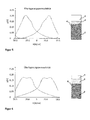
Fig. 4 , die linke Abbildung zeigt eine typische Folge von Messwerten der Überlagerungspermeabilität in Abhängigkeit von der magnetischen Feldstärke für einen Prüfkörper mit einer Schichtenfolge entsprechend der rechten Abbildung. -
Fig. 5 , die linke Abbildung zeigt eine typische Folge von Messwerten der Überlagerungspermeabilität in Abhängigkeit von der magnetischen Feldstärke für einen Prüfkörper mit einer Schichtenfolge entsprechend der rechten Abbildung. -
Fig. 6 , die linke Abbildung zeigt eine typische Folge von Messwerten der Überlagerungspermeabilität in Abhängigkeit von der magnetischen Feldstärke für einen Prüfkörper mit einer Schichtenfolge entsprechend der rechten Abbildung.
-
Fig. 1 shows an inventive arrangement comprising atest specimen 4 and a measuring device. The measuring device consists of asensor 5 and asensor electronics 6, which via a control measuring channel L are connected. Thetest piece 4 has threelayers sensor 5 is arranged on or near the surface of the test body and connected to thesensor electronics 6. Thesensor electronics 6 contains at least onecontroller 7 and anestimator 8 which generates a plurality of estimated results S dx1 , S dx2 to S dxn from function characteristics M 1 , M 2 to M 1 . -
Fig. 2 shows thetest specimen 4 with the layer thickness of the cover layer S d1 , the layer thickness of the diffusion layer S d3 , the layer thickness of the base layer S d2 and the total thickness of the specimen 4 S d4 . -
Fig. 3 shows a sequence of measured value pairs (f (x), x) to represent a dependence of the quantity f (x) of x. Furthermore, the graphical determination of the amplitude maximum, that is, the determination of the function characteristic M 4 is shown. The functional characteristics M 1 , M 2 and M 3 are in each case the half-width at 75%, 50% and 25% of the amplitude maximum M 4 . -
Fig. 4 The left-hand figure shows a typical sequence of superimposed permeability measurements as a function of the magnetic field strength for a test specimen with a layer sequence corresponding to the right figure. -
Fig. 5 The left-hand figure shows a typical sequence of superimposed permeability measurements as a function of the magnetic field strength for a test specimen with a layer sequence corresponding to the right figure. -
Fig. 6 The left-hand figure shows a typical sequence of superimposed permeability measurements as a function of the magnetic field strength for a test specimen with a layer sequence corresponding to the right figure.
Die Darstellung nach
Dargestellt ist ein Prüfkörper 4, der einen Schichtaufbau aufweist. Die Schichtdicken sind unbekannt und mit Hilfe des Sensors 5 und der Sensorelektronik 6 zu bestimmen. Die Schichten unterscheiden sich untereinander in ihren elektromagnetischen oder magnetischen Eigenschaften. So können die Schichten para-, dia-, ferro- oder antiferromagnetisch sein. Beispielhaft sei die äußere Deckschicht 1 paramagnetisch oder diamagnetisch und die Basisschicht 2 ferromagnetisch. Als Basisschicht wird die sensorfernste Schicht bezeichnet, die einen Beitrag zum Messsignal liefert. Schicht 3 sei eine Diffusionsschicht, die sowohl Atome der Schicht 1, als auch Atome der Schicht 2 enthält. Eine solche Diffusionsschicht entsteht beispielsweise bei der Prozessierung eines zu Beginn nur aus den Schichten 1 und 2 aufgebauten Körpers durch Einwirkung hoher Temperaturen über einen längeren Zeitraum. Schicht 1 ist die sensornächste Schicht und kann beispielsweise Atome von Aluminium, Silizium, Chrom und/oder Stickstoff enthalten, oder auch organische Polymere, beispielsweise Lacke aufweisen. Schicht 2 kann beispielsweise Atome von Eisen, Mangan, Kobalt enthalten oder daraus bestehen. Durch Prozessierung entsteht die Diffusionsschicht 3, die eine Mischung der Atome aus den benachbarten Schichten aufweist und sich dadurch in ihren elektromagnetischen Eigenschaften von den angrenzenden Schichten unterscheidet.Shown is a
Ein Sensor 5 ist nahe oder auf der Oberfläche des Prüfkörpers 4 und der Schicht 1 angeordnet. Der Abstand zur Oberfläche ist entweder Null, bekannt, wird gemessen oder, im Fall einer wiederholenden Messung, konstant gehalten. Der Sensor 5 erzeugt durch einen aus zumindest einer Spule aufgebauten Elektromagneten ein magnetisches Feld im Prüfkörper 4 welches durch einen Magnetfeldsensor, der Teil des Sensors 5 ist, gemessen wird. Die Sensorelektronik 6 ist ausgelegt, durch die Steuerung 7 den Elektromagneten so anzusteuern, dass das durch den Magnetfeldsensor gemessene Magnetfeld mit einem Vorgabewert übereinstimmt. Der Wert der magnetischen Feldstärke und dessen Zeitfunktion lassen sich so durch die Steuerung 7 beliebig an die Messaufgabe anpassen. Ebenfalls Teil des Sensors 5 ist eine Detektionsspule zur Messung der durch den Prüfkörper 4 erzeugten magnetischen Felder. Der Sensor 5 und die Steuerung 7 sind so ausgelegt, dass zumindest eine Oberwellenanalyse und die Messung der Überlagerungspermeabilität möglich sind.A
Bei der Oberwellenanalyse wird durch den Elektromagneten des Sensors 5 ein sinusförmiges magnetisches Wechselfeld erzeugt. Eine Magnetfeldsonde, beispielsweise eine Hallsonde, erfasst den Zeitverlauf der magnetischen Tangentialfeldstärke. Der Zeitverlauf der Tangentialfeldstärke wird bei Vorhandensein ferromagnetischer Materialien durch die Nichtlinearität der ferromagnetischen Hysterese verzerrt, es kommt zu Abweichungen der Kurvenform vom sinusförmigen Verlauf. Insbesondere in der Nähe der Nulldurchgänge zeigen sich deutliche Verzerrungen. Die ferromagnetische Hysterese verursacht im Signal der Tangentialfeldstärke neben der Grundschwingung ausgeprägte Oberwellenanteile (harmonische Schwingungen), die durch den nichtlinearen magnetischen Widerstand des Messobjekts hervorgerufen werden. Mithilfe einer Fast Fourier-Analyse können die Grund- und Oberwellenanteile numerisch bestimmt werden. Die Auswertesoftware des Messsystems beschreibt diese Oberwellenanteile durch charakteristische Kenngrößen M, beispielsweise in Form eines Klirrfaktors.In harmonic analysis, a sinusoidal alternating magnetic field is generated by the electromagnet of the
Die Wechselwirkung des Feldes mit den Schichten des Prüfkörpers 4 bildet sich im verzerrten Zeitsignal des Feldes und damit in den Oberwellenanteilen ab.The interaction of the field with the layers of the
Zur Messung der Überlagerungspermeabilität wird durch den Elektromagneten des Sensors 5 ein magnetisches Feld im Prüfkörper 4 erzeugt, das einer Kombination aus einem sinusförmigen magnetischen Erregerfeld und einem überlagerten höherfrequenten Wechselfeld entspricht. Beim durch das Erregerfeld verursachten, langsamen, quasistatischen Durchlaufen der magnetischen Hystereseschleife entstehen kleine Innenschleifen durch das Wechselfeld. Durch die Sensorelektronik wird die Überlagerungspermeabilität aus der Steigung der Innenschleifen in Abhängigkeit von der magnetischen Feldstärke des Erregerfeldes bestimmt.To measure the overlay permeability, a magnetic field in the
Vorzugsweise liegt die Frequenz des sich periodisch ändernden quasistatischen Erregerfeldes in einem Bereich zwischen 50 Hz und 500 Hz. Die Frequenz des Wechselfeldes ist größer 10 kHz, vorzugsweise circa 100 kHz. Vorteilhaft sind der Sensor 5 und die Sensorelektronik 6 ausgelegt, weitere Messungen durchzuführen, beispielsweise die Messung des magnetischen und/oder akustischen Barkhausenrauschens in Abhängigkeit von der magnetischen Feldstärke. Zusätzliche Messungen können die statistische Unsicherheit bei der Bestimmung der Schichtdicken des Prüfkörpers 4 verringern.Preferably, the frequency of the periodically changing quasistatic excitation field is in a range between 50 Hz and 500 Hz. The frequency of the alternating field is greater than 10 kHz, preferably approximately 100 kHz. Advantageously, the
Die im Rahmen der Oberwellenanalyse und der Messung der Überlagerungspermeabilität gemessenen Wertepaare, aber auch der im Rahmen weiterer Messungen erzeugten Wertepaare, setzen sich aus dem jeweiligen Messwert und dem Wert der magnetischen Feldstärke zusammen. Durch eine Vielzahl von Wertepaaren nähert sich die entstehende Wertefolge einer stetigen Funktion an, wodurch typische skalare Funktionskenngrößen M1, M2 bis Mi genau bestimmbar sind. Vorteilhaft werden für zumindest eine Wertefolge eine oder mehrerer Funktionskenngrößen M1, M2 bis Mi beispielsweise lokale, globale Maxima und/oder Minima oder Wendepunkte oder Halbwertsbreiten, insbesondere bei 75%, 50% und/oder 25% des zugehörigen lokalen Amplitudenmaximums bestimmt und dem Schätzer 8 zugeführt.The value pairs measured in the context of the harmonic analysis and the measurement of the superposition permeability, but also of the value pairs generated in the context of further measurements, are composed of the respective measured value and the value of the magnetic field strength. Through a multiplicity of pairs of values, the resulting sequence of values approximates to a continuous function, whereby typical scalar function characteristics M 1 , M 2 to M i can be determined exactly. Advantageously, one or more function characteristics M 1 , M 2 to M i, for example, local, global maxima and / or minima or inflection points or half widths, in particular at 75%, 50% and / or 25% of the associated local amplitude maximum are determined for at least one value sequence and supplied to the
Auch kann neben den vorher genannten Messungen von mehreren Wertepaaren die Messung in Bezug auf zumindest eine Materialeigenschaft auf einen Messwert bei einer ausgewählten festen magnetischen Feldstärke beschränkt sein, sodass dieser Messwert selbst als eine Eingangsgröße dem Schätzer 8 bereitgestellt werden kann. Beispielsweise kommt dies einer Messung des lokalen Maximums gleich, wenn der Funktionsverlauf bekannt ist und die magnetische Feldstärke für die Einzelmessung auf die Position des abgeschätzten lokalen Maximums gesetzt wird. Gewöhnlich werden jedoch mindestens zehn, mindestens hundert oder mindestens tausend, vorzugsweise eine sehr hohe Zahl an Wertepaaren gemessen, sodass sich die Funktionskenngrößen M1, M2 bis Mi mit großer Genauigkeit bestimmen lassen. Die Bestimmung erfolgt in der Steuerung 7 beispielsweise mit Hilfe eines Computers, Prozessors, Mikrocontrollers und zugehörigem Programm oder einer FPGA oder eines ASIC. Sowohl die Steuerung 7 als auch der Schätzer 8 können in Software implementiert sein, die auf einem Computer abgearbeitet wird.Also, in addition to the aforementioned measurements of multiple pairs of values, the measurement relative to at least one material property may be limited to a measurement at a selected fixed magnetic field strength, such that this measurement itself may be provided to the
Die von der Steuerung 7 bereitgestellten Funktionskenngrößen M1, M2 bis Mi werden dem Schätzer 8, zugeführt, der mit Hilfe eines statistischen Analyseverfahrens, das heißt mit einem an die Messaufgabe angepassten Modell, die Funktionskenngrößen M1, M2 bis Mi auf die Ausgangsgrößen Sdx1, Sdx2 bis Sdxn abbildet. Die einzelnen Ausgangsgrößen Sdx1, Sdx2 bis Sdxn entsprechen im Rahmen der Messgenauigkeit des Gesamtaufbaus den jeweiligen Schichtdicken Sd1, Sd2 bis Sdn des Prüfkörpers 4. Durch geeignete Anpassung oder Einstellung des Modells lassen sich alle Einzelschichtdicken und die Gesamtschichtdicke ermitteln.The function parameters M 1 , M 2 to M i provided by the
Vorzugsweise bildet der Schätzer 8 die Eingangsgrößen M1, M2 bis Mi durch ein Regressionsverfahren auf die Ausgangsgrößen Sdx1, Sdx2 bis Sdxn ab. Vorteilhaft kommt eine lineare Regression zur Anwendung, die mit einer linearen Funktion eine Menge von n Datenpunkten optimal im Sinne der kleinsten Summe der Fehlerquadrate annähert. Das Modell beschreibt den Messwert der Schichtdicke Sdxn als Polynom i-ten Grades ![]()
![]()
Das Modell wird durch die Regressionskoeffizienten an die Messaufgabe, das heißt den Prüfkörper angepasst. Dazu werden die Eingangsgrößen M1, M2 bis M1 an zumindest einem, vorzugsweise mehreren Prüfkörpern mit bekannter Schichtfolge und Schichtdicken Sd1, Sd2 usw. gemessen. Da der Schichtaufbau bekannt ist, sind auch die Ausgangsgrößen Sdx1, Sdx2 bis Sdxn bekannt, die bei Messfehler Null den Schichtdicken Sd1, Sd2 bis Sdn entsprechen würden. Durch die bekannten Eingangs- und Ausgangsgrößen lässt sich das Modell mit Ziel eines geringen Fehlers an die Messaufgabe anpassen, das heißt kalibrieren. Ein Prüfkörper mit bekanntem Schichtaufbau oder zumindest einer bekannten Schichtdicke, der zur Anpassung des Modells dient, wird Kalibrierkörper genannt.The model is adjusted by the regression coefficients to the measurement task, ie the test specimen. For this purpose the input values M 1, M 2 M 1 to be at at least one, preferably a plurality of specimens having a known sequence of layers and layer thicknesses S d1, S d2, etc. measured. Since the layer structure is known, the output variables S dx1 , S dx2 to S dxn are known, which would correspond to the layer thicknesses S d1 , S d2 to S dn at zero measurement errors. Due to the known input and output variables, the model can be adapted to the measuring task with the aim of a small error, that is to calibrate. A test specimen with a known layer structure or at least one known layer thickness which serves to adapt the model is called a calibration body.
Die Schichtdicke einer unmagnetischen Schicht oder unmagnetischer Schichten fließt indirekt in die Messung der magnetischen Eigenschaften ein, da sich durch die unmagnetischen Schichten der Abstand einer tiefliegenden magnetischen Schicht vom Sensor vergrößert. Damit sind durch den erfindungsgemäßen Aufbau auch unmagnetische Schichten der magnetischen Schichtdickenmessung zugänglich. Jede der Schichten des Prüfkörpers, ob magnetisch oder nicht, liefert einen Beitrag zu den Messsignalen, wenn die Basisschicht magnetisch ist.The layer thickness of a non-magnetic layer or non-magnetic layers is indirectly included in the measurement of the magnetic properties, since the distance between a low-lying magnetic layer and the sensor increases due to the non-magnetic layers. Thus, non-magnetic layers of the magnetic layer thickness measurement are accessible by the structure according to the invention. Each of the layers of the specimen, whether magnetic or not, provides a contribution to the measurement signals when the base layer is magnetic.
Der Prüfkörper 4 kann unter anderem folgende Schichtsysteme für Schicht 1 // Schicht 2 aufweisen:
- Aluminium, Silizium // Stahl
- Aluminium, Silizium / Diffusionsschicht /Stahl
- organisches Polymer // Stahl
- Aluminum, silicon // steel
- Aluminum, silicon / diffusion layer / steel
- organic polymer // steel
Die Basisschicht kann so dick sein, das Sie nicht vollständig in den Erfassungsbereich des erfindungsgemäßen Verfahrens oder/und Vorrichtung fällt. Dann lässt sich die Schichtdicke der Basisschicht und die Gesamtschichtdicke nicht auf Basis des erfindungsgemäßen Verfahrens, der Vorrichtung bestimmen. Die Schichtdicken der inneren Schichten im Erfassungsbereich lassen sich jedoch weiter bestimmen.The base layer may be so thick that it does not fully fall within the scope of the method and / or device of the invention. Then, the layer thickness of the base layer and the total layer thickness can not be determined based on the method of the invention, the device. However, the layer thicknesses of the inner layers in the detection area can be further determined.
- 11
- Deckschichttopcoat
- 22
- Basisschichtbase layer
- 33
- innere Schichtinner layer
- 44
- Prüfkörperspecimen
- 55
- Sensorsensor
- 66
- Sensorelektroniksensor electronics
- 77
- Steuerungcontrol
- 88th
- Schätzervaluer
Claims (15)
Applications Claiming Priority (1)
| Application Number | Priority Date | Filing Date | Title |
|---|---|---|---|
| DE102012017784.4A DE102012017784B4 (en) | 2012-09-07 | 2012-09-07 | Method, device and use of the device for nondestructive quantitative determination of layer thicknesses of a layered body |
Publications (3)
| Publication Number | Publication Date |
|---|---|
| EP2706351A2 true EP2706351A2 (en) | 2014-03-12 |
| EP2706351A3 EP2706351A3 (en) | 2014-04-02 |
| EP2706351B1 EP2706351B1 (en) | 2016-07-06 |
Family
ID=49036477
Family Applications (1)
| Application Number | Title | Priority Date | Filing Date |
|---|---|---|---|
| EP13182047.4A Active EP2706351B1 (en) | 2012-09-07 | 2013-08-28 | Method, device and use of the device for non-destructive quantitative determination of layer thicknesses of a body with layers |
Country Status (3)
| Country | Link |
|---|---|
| EP (1) | EP2706351B1 (en) |
| DE (1) | DE102012017784B4 (en) |
| ES (1) | ES2593305T3 (en) |
Cited By (2)
| Publication number | Priority date | Publication date | Assignee | Title |
|---|---|---|---|---|
| WO2016096661A1 (en) * | 2014-12-17 | 2016-06-23 | Compagnie Generale Des Etablissements Michelin | Method for measuring the thickness of a layer of rubber-like material |
| CN112748178A (en) * | 2020-12-25 | 2021-05-04 | 中国航发哈尔滨轴承有限公司 | Plane carburization sample determination method based on magnetic method |
Families Citing this family (1)
| Publication number | Priority date | Publication date | Assignee | Title |
|---|---|---|---|---|
| DE102019004240B4 (en) * | 2019-06-18 | 2024-04-25 | Mike Pfennig | Apparatus for testing steel wire ropes and method for its use |
Citations (3)
| Publication number | Priority date | Publication date | Assignee | Title |
|---|---|---|---|---|
| DE4119903A1 (en) | 1991-06-17 | 1992-12-24 | Helmut Fischer Gmbh & Co | METHOD AND DEVICE FOR MEASURING THIN LAYERS |
| DE102005046574A1 (en) | 2005-09-23 | 2007-04-05 | Fraunhofer-Gesellschaft zur Förderung der angewandten Forschung e.V. | Apparatus and method for non-destructive testing of components |
| US7259555B2 (en) | 2002-09-02 | 2007-08-21 | Stresstech Oy | Method for determining the hardening depth of steel |
Family Cites Families (6)
| Publication number | Priority date | Publication date | Assignee | Title |
|---|---|---|---|---|
| EP0100009B1 (en) * | 1982-07-09 | 1985-11-13 | Fraunhofer-Gesellschaft Zur Förderung Der Angewandten Forschung E.V. | Device for non destructive measuring of the case hardening depth of a material |
| FR2584190B1 (en) * | 1985-06-28 | 1987-09-18 | Ecole Nale Super Arts Metiers | METHOD AND DEVICE FOR DETERMINING THE VOLUME OF THE MAGNETIC COMPONENT CONTENT OF A MATERIAL |
| NO162537C (en) * | 1986-02-17 | 1990-01-10 | Dam Patent A S | PROCEDURE AND DEVICE FOR NON-DESTRUCTIVE MATERIAL TESTING. |
| DE4433772A1 (en) * | 1994-09-22 | 1996-03-28 | Micro Epsilon Messtechnik | Sensor arrangement and method for data acquisition with the sensor arrangement |
| US5619135A (en) | 1995-07-17 | 1997-04-08 | American Iron And Steel Institute | Steel characteristics measurement system using Barkhausen jump sum rate and magnetic field intensity and method of using same |
| US6201391B1 (en) | 1998-10-07 | 2001-03-13 | Southwest Research Institute | Nonlinear harmonics method and system for measuring degradation in protective coatings |
-
2012
- 2012-09-07 DE DE102012017784.4A patent/DE102012017784B4/en active Active
-
2013
- 2013-08-28 ES ES13182047.4T patent/ES2593305T3/en active Active
- 2013-08-28 EP EP13182047.4A patent/EP2706351B1/en active Active
Patent Citations (3)
| Publication number | Priority date | Publication date | Assignee | Title |
|---|---|---|---|---|
| DE4119903A1 (en) | 1991-06-17 | 1992-12-24 | Helmut Fischer Gmbh & Co | METHOD AND DEVICE FOR MEASURING THIN LAYERS |
| US7259555B2 (en) | 2002-09-02 | 2007-08-21 | Stresstech Oy | Method for determining the hardening depth of steel |
| DE102005046574A1 (en) | 2005-09-23 | 2007-04-05 | Fraunhofer-Gesellschaft zur Förderung der angewandten Forschung e.V. | Apparatus and method for non-destructive testing of components |
Cited By (4)
| Publication number | Priority date | Publication date | Assignee | Title |
|---|---|---|---|---|
| WO2016096661A1 (en) * | 2014-12-17 | 2016-06-23 | Compagnie Generale Des Etablissements Michelin | Method for measuring the thickness of a layer of rubber-like material |
| FR3030717A1 (en) * | 2014-12-17 | 2016-06-24 | Michelin & Cie | METHOD FOR MEASURING THE THICKNESS OF A LAYER OF RUBBER MATERIAL |
| US10190863B2 (en) | 2014-12-17 | 2019-01-29 | Compagnie Generale Des Etablissements Michelin | Method for measuring the thickness of a layer of rubber-like material |
| CN112748178A (en) * | 2020-12-25 | 2021-05-04 | 中国航发哈尔滨轴承有限公司 | Plane carburization sample determination method based on magnetic method |
Also Published As
| Publication number | Publication date |
|---|---|
| DE102012017784B4 (en) | 2018-08-23 |
| DE102012017784A1 (en) | 2014-04-03 |
| EP2706351B1 (en) | 2016-07-06 |
| EP2706351A3 (en) | 2014-04-02 |
| ES2593305T3 (en) | 2016-12-07 |
Similar Documents
| Publication | Publication Date | Title |
|---|---|---|
| DE602004003681T2 (en) | MEASURING THE REST AND THERMAL CAUSES LOAD IN A RAIL | |
| DE102007026540A1 (en) | Sample surface testing method, involves comparing data obtained for test sample with sample data, and testing condition of internal stress produced in test sample based on condition of internal stress of test sample | |
| EP2027430A1 (en) | Method for determining the layer thickness of an electrically conductive coating on an electrically conductive substrate | |
| EP2706351B1 (en) | Method, device and use of the device for non-destructive quantitative determination of layer thicknesses of a body with layers | |
| EP3368890A1 (en) | Method and devices for observing a magnetic field of a material volume, and use of the device | |
| DE102013015566A1 (en) | Method for the non-contact determination of a mechanical-technological characteristic of ferromagnetic metals and apparatus therefor | |
| EP0833150B1 (en) | Method and device for measuring the material characteristics of semi-finished products and parts | |
| DE102007001464A1 (en) | Method for determining the remaining service life and / or the fatigue state of components | |
| DE3537129C2 (en) | Method and device for non-destructive material testing, especially for thickness determination | |
| DE102006043554A1 (en) | Process for the non-destructive quality control of mechanically hardened surfaces of austenitic steel tubes | |
| Fricke et al. | In-situ characterization by eddy current testing of graded microstructural evolution in the core and peripheral zone during material conversion during case hardening | |
| DE102018130090B4 (en) | Method for determining microstructure variations in a sample and analysis device | |
| DE102008059032B4 (en) | Method and apparatus for determining whether a change in a substrate is present under a layer covering the substrate | |
| DE102017129150B4 (en) | Method and device for measuring the thickness of non-magnetizable layers on a magnetizable base material | |
| DE102014108664B4 (en) | Identification of components | |
| EP1216414B1 (en) | Method and device for carrying out the nondestructive material characterization of ferromagnetic substances | |
| DE102008037063A1 (en) | Method for testing coating, particularly lacquer on metallic component, involves forming component by compressing ball stamp, where impedance of barrier layer is measured between coating and component | |
| DE102005041089B3 (en) | Device for acquiring fluidized currents in an electrically conducting test object comprises magnetic field converters and induction coils arranged on a substrate | |
| Bobrov et al. | Micromagnetic analysis of residual stress distribution in 42CrMo4 steel after thermal and mechanical surface treatment | |
| DE102019208154A1 (en) | Method for determining a manufacturing quality of at least one component in a manufacturing method for a plurality of components and device for determining a manufacturing quality of at least one component in a manufacturing method for a plurality of components in a processing device | |
| WO2017071812A1 (en) | Method and devices for observing a magnetic field of a material volume, and use of the device | |
| DE102016006645A1 (en) | Method for calibrating a non-destructive measuring method for coating thickness measurement | |
| EP2063266B1 (en) | Strain-independent microstructure characterisation | |
| DE102021103803A1 (en) | Device and method for detecting material-internal mechanical states of a workpiece | |
| EP4073502A1 (en) | Method for determining a materials characteristic value of magnetizable metal bodies by means of a micromagnetic sensor assembly, and corresponding sensor assembly |
Legal Events
| Date | Code | Title | Description |
|---|---|---|---|
| PUAL | Search report despatched |
Free format text: ORIGINAL CODE: 0009013 |
|
| PUAI | Public reference made under article 153(3) epc to a published international application that has entered the european phase |
Free format text: ORIGINAL CODE: 0009012 |
|
| AK | Designated contracting states |
Kind code of ref document: A2 Designated state(s): AL AT BE BG CH CY CZ DE DK EE ES FI FR GB GR HR HU IE IS IT LI LT LU LV MC MK MT NL NO PL PT RO RS SE SI SK SM TR |
|
| AX | Request for extension of the european patent |
Extension state: BA ME |
|
| AK | Designated contracting states |
Kind code of ref document: A3 Designated state(s): AL AT BE BG CH CY CZ DE DK EE ES FI FR GB GR HR HU IE IS IT LI LT LU LV MC MK MT NL NO PL PT RO RS SE SI SK SM TR |
|
| AX | Request for extension of the european patent |
Extension state: BA ME |
|
| RIC1 | Information provided on ipc code assigned before grant |
Ipc: G01N 27/72 20060101AFI20140225BHEP |
|
| 17P | Request for examination filed |
Effective date: 20140923 |
|
| RBV | Designated contracting states (corrected) |
Designated state(s): AL AT BE BG CH CY CZ DE DK EE ES FI FR GB GR HR HU IE IS IT LI LT LU LV MC MK MT NL NO PL PT RO RS SE SI SK SM TR |
|
| 17Q | First examination report despatched |
Effective date: 20150414 |
|
| REG | Reference to a national code |
Ref country code: DE Ref legal event code: R079 Ref document number: 502013003589 Country of ref document: DE Free format text: PREVIOUS MAIN CLASS: G01N0027720000 Ipc: G01B0007060000 |
|
| GRAP | Despatch of communication of intention to grant a patent |
Free format text: ORIGINAL CODE: EPIDOSNIGR1 |
|
| RIC1 | Information provided on ipc code assigned before grant |
Ipc: G01B 7/06 20060101AFI20160203BHEP Ipc: G01N 27/72 20060101ALI20160203BHEP |
|
| INTG | Intention to grant announced |
Effective date: 20160222 |
|
| RAP1 | Party data changed (applicant data changed or rights of an application transferred) |
Owner name: FRAUNHOFER-GESELLSCHAFT ZUR FOERDERUNG DER ANGEWAN |
|
| GRAS | Grant fee paid |
Free format text: ORIGINAL CODE: EPIDOSNIGR3 |
|
| GRAA | (expected) grant |
Free format text: ORIGINAL CODE: 0009210 |
|
| AK | Designated contracting states |
Kind code of ref document: B1 Designated state(s): AL AT BE BG CH CY CZ DE DK EE ES FI FR GB GR HR HU IE IS IT LI LT LU LV MC MK MT NL NO PL PT RO RS SE SI SK SM TR |
|
| REG | Reference to a national code |
Ref country code: GB Ref legal event code: FG4D Free format text: NOT ENGLISH |
|
| REG | Reference to a national code |
Ref country code: AT Ref legal event code: REF Ref document number: 811030 Country of ref document: AT Kind code of ref document: T Effective date: 20160715 Ref country code: CH Ref legal event code: EP |
|
| REG | Reference to a national code |
Ref country code: IE Ref legal event code: FG4D Free format text: LANGUAGE OF EP DOCUMENT: GERMAN |
|
| REG | Reference to a national code |
Ref country code: DE Ref legal event code: R096 Ref document number: 502013003589 Country of ref document: DE |
|
| REG | Reference to a national code |
Ref country code: FR Ref legal event code: PLFP Year of fee payment: 4 |
|
| REG | Reference to a national code |
Ref country code: NL Ref legal event code: MP Effective date: 20160706 |
|
| REG | Reference to a national code |
Ref country code: LT Ref legal event code: MG4D |
|
| REG | Reference to a national code |
Ref country code: ES Ref legal event code: FG2A Ref document number: 2593305 Country of ref document: ES Kind code of ref document: T3 Effective date: 20161207 |
|
| PG25 | Lapsed in a contracting state [announced via postgrant information from national office to epo] |
Ref country code: BE Free format text: LAPSE BECAUSE OF NON-PAYMENT OF DUE FEES Effective date: 20160831 |
|
| PG25 | Lapsed in a contracting state [announced via postgrant information from national office to epo] |
Ref country code: FI Free format text: LAPSE BECAUSE OF FAILURE TO SUBMIT A TRANSLATION OF THE DESCRIPTION OR TO PAY THE FEE WITHIN THE PRESCRIBED TIME-LIMIT Effective date: 20160706 Ref country code: NO Free format text: LAPSE BECAUSE OF FAILURE TO SUBMIT A TRANSLATION OF THE DESCRIPTION OR TO PAY THE FEE WITHIN THE PRESCRIBED TIME-LIMIT Effective date: 20161006 Ref country code: IS Free format text: LAPSE BECAUSE OF FAILURE TO SUBMIT A TRANSLATION OF THE DESCRIPTION OR TO PAY THE FEE WITHIN THE PRESCRIBED TIME-LIMIT Effective date: 20161106 Ref country code: LT Free format text: LAPSE BECAUSE OF FAILURE TO SUBMIT A TRANSLATION OF THE DESCRIPTION OR TO PAY THE FEE WITHIN THE PRESCRIBED TIME-LIMIT Effective date: 20160706 Ref country code: HR Free format text: LAPSE BECAUSE OF FAILURE TO SUBMIT A TRANSLATION OF THE DESCRIPTION OR TO PAY THE FEE WITHIN THE PRESCRIBED TIME-LIMIT Effective date: 20160706 Ref country code: IT Free format text: LAPSE BECAUSE OF FAILURE TO SUBMIT A TRANSLATION OF THE DESCRIPTION OR TO PAY THE FEE WITHIN THE PRESCRIBED TIME-LIMIT Effective date: 20160706 Ref country code: NL Free format text: LAPSE BECAUSE OF FAILURE TO SUBMIT A TRANSLATION OF THE DESCRIPTION OR TO PAY THE FEE WITHIN THE PRESCRIBED TIME-LIMIT Effective date: 20160706 Ref country code: RS Free format text: LAPSE BECAUSE OF FAILURE TO SUBMIT A TRANSLATION OF THE DESCRIPTION OR TO PAY THE FEE WITHIN THE PRESCRIBED TIME-LIMIT Effective date: 20160706 |
|
| PG25 | Lapsed in a contracting state [announced via postgrant information from national office to epo] |
Ref country code: PT Free format text: LAPSE BECAUSE OF FAILURE TO SUBMIT A TRANSLATION OF THE DESCRIPTION OR TO PAY THE FEE WITHIN THE PRESCRIBED TIME-LIMIT Effective date: 20161107 Ref country code: LV Free format text: LAPSE BECAUSE OF FAILURE TO SUBMIT A TRANSLATION OF THE DESCRIPTION OR TO PAY THE FEE WITHIN THE PRESCRIBED TIME-LIMIT Effective date: 20160706 Ref country code: GR Free format text: LAPSE BECAUSE OF FAILURE TO SUBMIT A TRANSLATION OF THE DESCRIPTION OR TO PAY THE FEE WITHIN THE PRESCRIBED TIME-LIMIT Effective date: 20161007 Ref country code: SE Free format text: LAPSE BECAUSE OF FAILURE TO SUBMIT A TRANSLATION OF THE DESCRIPTION OR TO PAY THE FEE WITHIN THE PRESCRIBED TIME-LIMIT Effective date: 20160706 Ref country code: PL Free format text: LAPSE BECAUSE OF FAILURE TO SUBMIT A TRANSLATION OF THE DESCRIPTION OR TO PAY THE FEE WITHIN THE PRESCRIBED TIME-LIMIT Effective date: 20160706 |
|
| REG | Reference to a national code |
Ref country code: CH Ref legal event code: PL |
|
| REG | Reference to a national code |
Ref country code: DE Ref legal event code: R097 Ref document number: 502013003589 Country of ref document: DE |
|
| PG25 | Lapsed in a contracting state [announced via postgrant information from national office to epo] |
Ref country code: MC Free format text: LAPSE BECAUSE OF FAILURE TO SUBMIT A TRANSLATION OF THE DESCRIPTION OR TO PAY THE FEE WITHIN THE PRESCRIBED TIME-LIMIT Effective date: 20160706 Ref country code: EE Free format text: LAPSE BECAUSE OF FAILURE TO SUBMIT A TRANSLATION OF THE DESCRIPTION OR TO PAY THE FEE WITHIN THE PRESCRIBED TIME-LIMIT Effective date: 20160706 Ref country code: RO Free format text: LAPSE BECAUSE OF FAILURE TO SUBMIT A TRANSLATION OF THE DESCRIPTION OR TO PAY THE FEE WITHIN THE PRESCRIBED TIME-LIMIT Effective date: 20160706 Ref country code: CH Free format text: LAPSE BECAUSE OF NON-PAYMENT OF DUE FEES Effective date: 20160831 Ref country code: LI Free format text: LAPSE BECAUSE OF NON-PAYMENT OF DUE FEES Effective date: 20160831 |
|
| PLBE | No opposition filed within time limit |
Free format text: ORIGINAL CODE: 0009261 |
|
| STAA | Information on the status of an ep patent application or granted ep patent |
Free format text: STATUS: NO OPPOSITION FILED WITHIN TIME LIMIT |
|
| PG25 | Lapsed in a contracting state [announced via postgrant information from national office to epo] |
Ref country code: BG Free format text: LAPSE BECAUSE OF FAILURE TO SUBMIT A TRANSLATION OF THE DESCRIPTION OR TO PAY THE FEE WITHIN THE PRESCRIBED TIME-LIMIT Effective date: 20161006 Ref country code: SK Free format text: LAPSE BECAUSE OF FAILURE TO SUBMIT A TRANSLATION OF THE DESCRIPTION OR TO PAY THE FEE WITHIN THE PRESCRIBED TIME-LIMIT Effective date: 20160706 Ref country code: DK Free format text: LAPSE BECAUSE OF FAILURE TO SUBMIT A TRANSLATION OF THE DESCRIPTION OR TO PAY THE FEE WITHIN THE PRESCRIBED TIME-LIMIT Effective date: 20160706 Ref country code: SM Free format text: LAPSE BECAUSE OF FAILURE TO SUBMIT A TRANSLATION OF THE DESCRIPTION OR TO PAY THE FEE WITHIN THE PRESCRIBED TIME-LIMIT Effective date: 20160706 Ref country code: CZ Free format text: LAPSE BECAUSE OF FAILURE TO SUBMIT A TRANSLATION OF THE DESCRIPTION OR TO PAY THE FEE WITHIN THE PRESCRIBED TIME-LIMIT Effective date: 20160706 |
|
| REG | Reference to a national code |
Ref country code: IE Ref legal event code: MM4A |
|
| 26N | No opposition filed |
Effective date: 20170407 |
|
| PG25 | Lapsed in a contracting state [announced via postgrant information from national office to epo] |
Ref country code: IE Free format text: LAPSE BECAUSE OF NON-PAYMENT OF DUE FEES Effective date: 20160828 |
|
| REG | Reference to a national code |
Ref country code: FR Ref legal event code: PLFP Year of fee payment: 5 |
|
| PG25 | Lapsed in a contracting state [announced via postgrant information from national office to epo] |
Ref country code: SI Free format text: LAPSE BECAUSE OF FAILURE TO SUBMIT A TRANSLATION OF THE DESCRIPTION OR TO PAY THE FEE WITHIN THE PRESCRIBED TIME-LIMIT Effective date: 20160706 Ref country code: LU Free format text: LAPSE BECAUSE OF NON-PAYMENT OF DUE FEES Effective date: 20160828 |
|
| PG25 | Lapsed in a contracting state [announced via postgrant information from national office to epo] |
Ref country code: CY Free format text: LAPSE BECAUSE OF FAILURE TO SUBMIT A TRANSLATION OF THE DESCRIPTION OR TO PAY THE FEE WITHIN THE PRESCRIBED TIME-LIMIT Effective date: 20160706 Ref country code: HU Free format text: LAPSE BECAUSE OF FAILURE TO SUBMIT A TRANSLATION OF THE DESCRIPTION OR TO PAY THE FEE WITHIN THE PRESCRIBED TIME-LIMIT; INVALID AB INITIO Effective date: 20130828 |
|
| PG25 | Lapsed in a contracting state [announced via postgrant information from national office to epo] |
Ref country code: MT Free format text: LAPSE BECAUSE OF FAILURE TO SUBMIT A TRANSLATION OF THE DESCRIPTION OR TO PAY THE FEE WITHIN THE PRESCRIBED TIME-LIMIT Effective date: 20160706 Ref country code: MK Free format text: LAPSE BECAUSE OF FAILURE TO SUBMIT A TRANSLATION OF THE DESCRIPTION OR TO PAY THE FEE WITHIN THE PRESCRIBED TIME-LIMIT Effective date: 20160706 |
|
| REG | Reference to a national code |
Ref country code: FR Ref legal event code: PLFP Year of fee payment: 6 |
|
| PG25 | Lapsed in a contracting state [announced via postgrant information from national office to epo] |
Ref country code: AL Free format text: LAPSE BECAUSE OF FAILURE TO SUBMIT A TRANSLATION OF THE DESCRIPTION OR TO PAY THE FEE WITHIN THE PRESCRIBED TIME-LIMIT Effective date: 20160706 Ref country code: TR Free format text: LAPSE BECAUSE OF FAILURE TO SUBMIT A TRANSLATION OF THE DESCRIPTION OR TO PAY THE FEE WITHIN THE PRESCRIBED TIME-LIMIT Effective date: 20160706 |
|
| REG | Reference to a national code |
Ref country code: AT Ref legal event code: MM01 Ref document number: 811030 Country of ref document: AT Kind code of ref document: T Effective date: 20180828 |
|
| PG25 | Lapsed in a contracting state [announced via postgrant information from national office to epo] |
Ref country code: AT Free format text: LAPSE BECAUSE OF NON-PAYMENT OF DUE FEES Effective date: 20180828 |
|
| PGFP | Annual fee paid to national office [announced via postgrant information from national office to epo] |
Ref country code: FR Payment date: 20210823 Year of fee payment: 9 |
|
| PGFP | Annual fee paid to national office [announced via postgrant information from national office to epo] |
Ref country code: ES Payment date: 20210917 Year of fee payment: 9 Ref country code: GB Payment date: 20210824 Year of fee payment: 9 |
|
| GBPC | Gb: european patent ceased through non-payment of renewal fee |
Effective date: 20220828 |
|
| P01 | Opt-out of the competence of the unified patent court (upc) registered |
Effective date: 20230524 |
|
| PG25 | Lapsed in a contracting state [announced via postgrant information from national office to epo] |
Ref country code: FR Free format text: LAPSE BECAUSE OF NON-PAYMENT OF DUE FEES Effective date: 20220831 |
|
| REG | Reference to a national code |
Ref country code: ES Ref legal event code: FD2A Effective date: 20230929 |
|
| PG25 | Lapsed in a contracting state [announced via postgrant information from national office to epo] |
Ref country code: GB Free format text: LAPSE BECAUSE OF NON-PAYMENT OF DUE FEES Effective date: 20220828 Ref country code: ES Free format text: LAPSE BECAUSE OF NON-PAYMENT OF DUE FEES Effective date: 20220829 |
|
| PGFP | Annual fee paid to national office [announced via postgrant information from national office to epo] |
Ref country code: DE Payment date: 20230822 Year of fee payment: 11 |