EP2706221B1 - Ensemble de soupape destiné à un injecteur de carburant et injecteur de carburant - Google Patents
Ensemble de soupape destiné à un injecteur de carburant et injecteur de carburant Download PDFInfo
- Publication number
- EP2706221B1 EP2706221B1 EP12183513.6A EP12183513A EP2706221B1 EP 2706221 B1 EP2706221 B1 EP 2706221B1 EP 12183513 A EP12183513 A EP 12183513A EP 2706221 B1 EP2706221 B1 EP 2706221B1
- Authority
- EP
- European Patent Office
- Prior art keywords
- armature
- needle
- elastic member
- valve assembly
- valve
- Prior art date
- Legal status (The legal status is an assumption and is not a legal conclusion. Google has not performed a legal analysis and makes no representation as to the accuracy of the status listed.)
- Not-in-force
Links
Images


Classifications
-
- F—MECHANICAL ENGINEERING; LIGHTING; HEATING; WEAPONS; BLASTING
- F02—COMBUSTION ENGINES; HOT-GAS OR COMBUSTION-PRODUCT ENGINE PLANTS
- F02M—SUPPLYING COMBUSTION ENGINES IN GENERAL WITH COMBUSTIBLE MIXTURES OR CONSTITUENTS THEREOF
- F02M51/00—Fuel-injection apparatus characterised by being operated electrically
- F02M51/06—Injectors peculiar thereto with means directly operating the valve needle
- F02M51/061—Injectors peculiar thereto with means directly operating the valve needle using electromagnetic operating means
- F02M51/0625—Injectors peculiar thereto with means directly operating the valve needle using electromagnetic operating means characterised by arrangement of mobile armatures
- F02M51/0635—Injectors peculiar thereto with means directly operating the valve needle using electromagnetic operating means characterised by arrangement of mobile armatures having a plate-shaped or undulated armature not entering the winding
- F02M51/066—Injectors peculiar thereto with means directly operating the valve needle using electromagnetic operating means characterised by arrangement of mobile armatures having a plate-shaped or undulated armature not entering the winding the armature and the valve being allowed to move relatively to each other or not being attached to each other
-
- F—MECHANICAL ENGINEERING; LIGHTING; HEATING; WEAPONS; BLASTING
- F02—COMBUSTION ENGINES; HOT-GAS OR COMBUSTION-PRODUCT ENGINE PLANTS
- F02M—SUPPLYING COMBUSTION ENGINES IN GENERAL WITH COMBUSTIBLE MIXTURES OR CONSTITUENTS THEREOF
- F02M51/00—Fuel-injection apparatus characterised by being operated electrically
- F02M51/06—Injectors peculiar thereto with means directly operating the valve needle
- F02M51/061—Injectors peculiar thereto with means directly operating the valve needle using electromagnetic operating means
- F02M51/0625—Injectors peculiar thereto with means directly operating the valve needle using electromagnetic operating means characterised by arrangement of mobile armatures
- F02M51/0635—Injectors peculiar thereto with means directly operating the valve needle using electromagnetic operating means characterised by arrangement of mobile armatures having a plate-shaped or undulated armature not entering the winding
- F02M51/0642—Injectors peculiar thereto with means directly operating the valve needle using electromagnetic operating means characterised by arrangement of mobile armatures having a plate-shaped or undulated armature not entering the winding the armature having a valve attached thereto
- F02M51/0653—Injectors peculiar thereto with means directly operating the valve needle using electromagnetic operating means characterised by arrangement of mobile armatures having a plate-shaped or undulated armature not entering the winding the armature having a valve attached thereto the valve being an elongated body, e.g. a needle valve
-
- F—MECHANICAL ENGINEERING; LIGHTING; HEATING; WEAPONS; BLASTING
- F02—COMBUSTION ENGINES; HOT-GAS OR COMBUSTION-PRODUCT ENGINE PLANTS
- F02M—SUPPLYING COMBUSTION ENGINES IN GENERAL WITH COMBUSTIBLE MIXTURES OR CONSTITUENTS THEREOF
- F02M51/00—Fuel-injection apparatus characterised by being operated electrically
- F02M51/06—Injectors peculiar thereto with means directly operating the valve needle
- F02M51/061—Injectors peculiar thereto with means directly operating the valve needle using electromagnetic operating means
- F02M51/0625—Injectors peculiar thereto with means directly operating the valve needle using electromagnetic operating means characterised by arrangement of mobile armatures
- F02M51/0664—Injectors peculiar thereto with means directly operating the valve needle using electromagnetic operating means characterised by arrangement of mobile armatures having a cylindrically or partly cylindrically shaped armature, e.g. entering the winding; having a plate-shaped or undulated armature entering the winding
- F02M51/0671—Injectors peculiar thereto with means directly operating the valve needle using electromagnetic operating means characterised by arrangement of mobile armatures having a cylindrically or partly cylindrically shaped armature, e.g. entering the winding; having a plate-shaped or undulated armature entering the winding the armature having an elongated valve body attached thereto
- F02M51/0682—Injectors peculiar thereto with means directly operating the valve needle using electromagnetic operating means characterised by arrangement of mobile armatures having a cylindrically or partly cylindrically shaped armature, e.g. entering the winding; having a plate-shaped or undulated armature entering the winding the armature having an elongated valve body attached thereto the body being hollow and its interior communicating with the fuel flow
-
- F—MECHANICAL ENGINEERING; LIGHTING; HEATING; WEAPONS; BLASTING
- F02—COMBUSTION ENGINES; HOT-GAS OR COMBUSTION-PRODUCT ENGINE PLANTS
- F02M—SUPPLYING COMBUSTION ENGINES IN GENERAL WITH COMBUSTIBLE MIXTURES OR CONSTITUENTS THEREOF
- F02M51/00—Fuel-injection apparatus characterised by being operated electrically
- F02M51/06—Injectors peculiar thereto with means directly operating the valve needle
- F02M51/061—Injectors peculiar thereto with means directly operating the valve needle using electromagnetic operating means
- F02M51/0625—Injectors peculiar thereto with means directly operating the valve needle using electromagnetic operating means characterised by arrangement of mobile armatures
- F02M51/0664—Injectors peculiar thereto with means directly operating the valve needle using electromagnetic operating means characterised by arrangement of mobile armatures having a cylindrically or partly cylindrically shaped armature, e.g. entering the winding; having a plate-shaped or undulated armature entering the winding
- F02M51/0685—Injectors peculiar thereto with means directly operating the valve needle using electromagnetic operating means characterised by arrangement of mobile armatures having a cylindrically or partly cylindrically shaped armature, e.g. entering the winding; having a plate-shaped or undulated armature entering the winding the armature and the valve being allowed to move relatively to each other or not being attached to each other
-
- F—MECHANICAL ENGINEERING; LIGHTING; HEATING; WEAPONS; BLASTING
- F02—COMBUSTION ENGINES; HOT-GAS OR COMBUSTION-PRODUCT ENGINE PLANTS
- F02M—SUPPLYING COMBUSTION ENGINES IN GENERAL WITH COMBUSTIBLE MIXTURES OR CONSTITUENTS THEREOF
- F02M61/00—Fuel-injectors not provided for in groups F02M39/00 - F02M57/00 or F02M67/00
- F02M61/16—Details not provided for in, or of interest apart from, the apparatus of groups F02M61/02 - F02M61/14
- F02M61/20—Closing valves mechanically, e.g. arrangements of springs or weights or permanent magnets; Damping of valve lift
-
- F—MECHANICAL ENGINEERING; LIGHTING; HEATING; WEAPONS; BLASTING
- F02—COMBUSTION ENGINES; HOT-GAS OR COMBUSTION-PRODUCT ENGINE PLANTS
- F02M—SUPPLYING COMBUSTION ENGINES IN GENERAL WITH COMBUSTIBLE MIXTURES OR CONSTITUENTS THEREOF
- F02M63/00—Other fuel-injection apparatus having pertinent characteristics not provided for in groups F02M39/00 - F02M57/00 or F02M67/00; Details, component parts, or accessories of fuel-injection apparatus, not provided for in, or of interest apart from, the apparatus of groups F02M39/00 - F02M61/00 or F02M67/00; Combination of fuel pump with other devices, e.g. lubricating oil pump
- F02M63/0012—Valves
- F02M63/0014—Valves characterised by the valve actuating means
- F02M63/0015—Valves characterised by the valve actuating means electrical, e.g. using solenoid
- F02M63/0017—Valves characterised by the valve actuating means electrical, e.g. using solenoid using electromagnetic operating means
- F02M63/0021—Valves characterised by the valve actuating means electrical, e.g. using solenoid using electromagnetic operating means characterised by the arrangement of mobile armatures
- F02M63/0022—Valves characterised by the valve actuating means electrical, e.g. using solenoid using electromagnetic operating means characterised by the arrangement of mobile armatures the armature and the valve being allowed to move relatively to each other
-
- F—MECHANICAL ENGINEERING; LIGHTING; HEATING; WEAPONS; BLASTING
- F02—COMBUSTION ENGINES; HOT-GAS OR COMBUSTION-PRODUCT ENGINE PLANTS
- F02M—SUPPLYING COMBUSTION ENGINES IN GENERAL WITH COMBUSTIBLE MIXTURES OR CONSTITUENTS THEREOF
- F02M2200/00—Details of fuel-injection apparatus, not otherwise provided for
- F02M2200/26—Fuel-injection apparatus with elastically deformable elements other than coil springs
-
- F—MECHANICAL ENGINEERING; LIGHTING; HEATING; WEAPONS; BLASTING
- F02—COMBUSTION ENGINES; HOT-GAS OR COMBUSTION-PRODUCT ENGINE PLANTS
- F02M—SUPPLYING COMBUSTION ENGINES IN GENERAL WITH COMBUSTIBLE MIXTURES OR CONSTITUENTS THEREOF
- F02M2200/00—Details of fuel-injection apparatus, not otherwise provided for
- F02M2200/50—Arrangements of springs for valves used in fuel injectors or fuel injection pumps
- F02M2200/502—Springs biasing the valve member to the open position
-
- F—MECHANICAL ENGINEERING; LIGHTING; HEATING; WEAPONS; BLASTING
- F16—ENGINEERING ELEMENTS AND UNITS; GENERAL MEASURES FOR PRODUCING AND MAINTAINING EFFECTIVE FUNCTIONING OF MACHINES OR INSTALLATIONS; THERMAL INSULATION IN GENERAL
- F16F—SPRINGS; SHOCK-ABSORBERS; MEANS FOR DAMPING VIBRATION
- F16F1/00—Springs
- F16F1/02—Springs made of steel or other material having low internal friction; Wound, torsion, leaf, cup, ring or the like springs, the material of the spring not being relevant
- F16F1/32—Belleville-type springs
- F16F1/324—Belleville-type springs characterised by having tongues or arms directed in a generally radial direction, i.e. diaphragm-type springs
Definitions
- the present disclosure relates to a valve assembly for a fuel injector and to a fuel injector.
- Fuel injectors may be used for example in internal combustion engines for dosing fuel into an intake manifold of the internal combustion engine or directly to the combustion chamber of a cylinder of the internal combustion engine.
- the fuel injectors may be operable to dose the fuel under high pressures, for example in the range of up to 200 bar in the case of gasoline engines and of 2000 bar or more in the case of diesel engines.
- EP 0851116 A2 discloses a metering valve which has a shutter for a discharge conduit, and an electromagnet for controlling an armature disconnected from a respective stem and sliding along the stem by means of a respective sleeve.
- the stem is pushed by a first spring to keep the shutter in the closed position.
- the armature is held axially resting against the stem by a second spring preloaded between the armature and an annular shoulder of the stem, so as not to affect the action of the first spring.
- valve assembly for a fuel injector having the features of claim 1. Further embodiments and developments of the valve assembly and the fuel injector are specified in the dependent claims.
- a valve assembly for a fuel injector is specified.
- a fuel injector is specified, the fuel injector having the valve assembly.
- the fuel may, for example, be one of gasoline, diesel, and/or ethanol.
- the valve assembly comprises a valve body.
- the valve body has a longitudinal axis.
- the valve assembly further comprises a valve needle, an armature and an elastic member.
- the valve body has a cavity.
- the cavity may extend - in particular in longitudinal direction - from a fuel inlet opening of the valve body to a fuel outlet opening of the valve body.
- the fuel outlet opening is preferably comprised by an injection nozzle of the valve body.
- the valve needle and the armature are preferably arranged in the cavity.
- the valve needle is axially moveable in a first direction and in a second direction, opposite the first direction, with respect to the valve body.
- the needle is in particular axially moveable between a closing position and further positions, for example between a closing position and an opening position.
- the needle may have a tip, which in particular sealingly rests on a valve seat of the valve body when the needle is in the closing position in order to prevent fuel from leaving the valve assembly through the fuel outlet opening.
- the needle is for example axially moveable away from the closing position - in particular towards the opening position - in the first direction.
- the armature is also axially moveable in the first and in the second direction with respect to the valve body. It is biased in the first direction by means of the elastic member. In other words, the elastic member exerts a force on the armature, the force being directed in the first direction.
- the needle when moving in the second direction to the closing position, is operable to mechanically interact with the armature for moving the armature in the second direction to a first position against the bias of the elastic member.
- the armature is coupled to the needle in such fashion, that the needle exerts a force in the second direction on the armature to move the armature in the second direction when the needle moves in the second direction to the closing position.
- the needle in particular takes the armature with it to the first position when it is moving in the second direction to the closing position. Expediently, the armature may reach the first position when the needle reaches the closing position.
- the needle has a flange - sometimes also called a collar - which is operable to transfer a force to the armature in the second direction.
- the flange may be manufactured separately from a main barrel or cylinder of the needle and rigidly fixed to the barrel or cylinder so that relative axial movement is prevented.
- the flange may abut the armature when the needle is moving in the second direction.
- the flange and the elastic member may in particular be arranged on opposite sides of the armature.
- the valve assembly comprises a spring which is operable to exert a force on the needle for moving the needle in the second direction to the closing position.
- the needle may expediently be biased with a given force in the second direction when it is in the closing position, for example by means of the spring.
- the armature is in particular operable to interact mechanically with the needle to move the needle in the first direction, away from the closing position and in particular towards the opening position, when the armature moves in the first direction from its first position.
- the armature interacts with the needle via the flange.
- the armature is also axially moveable with respect to the needle so that, at least when the needle is in the closing position, the armature is moveable from the first position further in the second direction to a second position against the bias of the elastic member.
- the elastic member has a plurality of beams.
- Each beam has a first end and a second end.
- the first end and the second end of each beam are axially offset with respect to each other.
- the first end and the second end of each beam are also radially offset with respect to each other.
- the beams in particular extend obliquely with respect to the longitudinal axis.
- the main extension directions of the beams in top view along the axis are in particular radial directions, having the longitudinal axis as a center.
- the armature is operable to reduce an axial offset between the first end and the second end of each beam when it is moving from the first to the second position.
- the armature is operable to bend the beams when moving from the first towards the second position. In this way, the armature is operable to compress the elastic member.
- the valve assembly is configured for dissipating kinetic energy of the armature, when the armature is moving from the first towards the second position by means of mechanical interaction of the elastic member of the armature and/or the needle and/or the fuel.
- the valve assembly may be configured to dissipate kinetic energy by means of at least one of the following: friction between the beams and the armature, friction between the beams and the needle, compression and/or displacement of fuel by means of deformation of the beams.
- the needle When the valve assembly is operated for bringing the valve assembly from an opened state to a closed state - also referred to as closing event -, the needle is moved in the second direction to the closing position.
- the needle is biased in the second direction by a spring which mechanically interacts with the needle to move it in the second direction towards the closing position during the closing event.
- the needle On its way to the closing position, the needle takes the armature with it in the second direction to the first position.
- movement of the needle in the second direction may be stopped by interaction with the valve body. For example, the tip of the needle hits the valve seat when the needle reaches the closing position.
- the armature reaches the first position with a certain velocity, corresponding to a given kinetic energy.
- the armature moves further in the second direction from the first position to the second position. Due to this movement against the bias of the elastic member, the elastic member is compressed by the deformation of the beams. In this way, the kinetic energy, which the armature has in the first position, is partially converted into a given potential energy of the elastic member. Another part of the kinetic energy is dissipated, for example by friction between the elastic member and the armature.
- the armature comes to a rest when it has reached the second position.
- the compressed elastic member subsequently forces the armature to move back in the first direction to the first position.
- the armature when reaching the first position again, in particular mechanically interacts with the needle to transfer a force to the needle in the first direction. For example, the armature hits the flange of the needle when it returns to the first position. Since its kinetic energy has been partially dissipated by means of interaction with the elastic member, the force exerted by the armature on the needle during this armature-needle bounce is advantageously reduced. In this way, the danger is advantageously reduced that the valve reopens and that fuel is dispensed unintentionally through the fuel outlet opening. Therefore, a particularly precise dosing of the fuel is achievable.
- the elastic member is provided to bias the armature with a force in the first direction, the force being independent of an axial position of the armature.
- the spring force of the elastic member may be substantially or completely independent of the compression of the elastic member in axial direction. In particular it is substantially or completely independent of the axial offset of the first and the second ends at least under operating conditions of the valve assembly.
- valve assembly may be particularly reliable and reproducible in this way.
- valve assembly is particularly insensitive with respect to production tolerances or mounting tolerances of its constituent parts which may lead to different absolute values of the respective axial offset between the first and second ends of the beams.
- the elastic member radially surrounds the needle and is formed in such fashion that the first ends of the beams are facing the needle and are arranged at a radial distance from the needle when the armature is in the first position.
- the beams are elastically deformable in such fashion that the radial distance between the first ends and the needle decreases when the armature moves from the first towards the second position.
- the first ends or at least one of the first ends abuts the needle when the armature is in the second position. In this way, particularly effective dissipation of the kinetic energy of the armature is possible by means of friction between the beams and the needle.
- the beams are arranged evenly spaced around the needle in a top view along the longitudinal axis. This allows for a well balanced force distribution in angular direction around the longitudinal axis.
- the elastic member has the basic shape of a conical shell with an upper inner edge and a lower outer edge.
- the upper inner edge preferable faces the armature.
- the lower outer edge preferably resides against the valve body. It is also conceivable that the upper inner edge resides against the valve body and the lower outer edge faces, and in particular abuts, the armature.
- the expressions "upper edge” and “lower edge” in particular refer to the position with respect to the tip of the cone of which the conical shell is a section. The upper edge adjoins the tip, while the lower edge is remote from the tip.
- the upper inner edge of the conical shell is discontinuous. It is expediently formed by the first ends of the beams.
- the elastic member for example, has a plurality of beams and a plurality of slots. The beams and slots are arranged in angular direction around the longitudinal axis in alternating fashion, i.e. each two neighboring beams being separated from one another by one of the slots.
- the elastic member may also have a circumferential ring section, which is in particular a continuous section that extends completely circumferentially around the longitudinal axis and - in top view along the longitudinal axis - around the beams.
- the ring section expediently comprises the lower outer edge.
- the beams are preferably anchored to the ring section at their second ends.
- the beams and the ring section are formed as a one piece element and the beams merge with the ring section at their second ends.
- Figures 1, 2 and 3 show a valve assembly according to an exemplary embodiment in an opened state ( figure 1 ) in a closed state ( figure 2 ) and in a state during the closing event ( figure 3 ).
- the valve assembly 1 comprises a valve body 10 having a longitudinal axis L.
- the valve body 10 comprises a cavity 110.
- the cavity 110 extends through the valve body 10 in axial direction L from a fuel inlet opening 120 of the valve body 10 to the injection nozzle 130 of the valve body 10, the injection nozzle 130 having a fuel outlet opening.
- a valve needle 20 is arranged in the cavity 110.
- the needle 20 is axially moveable in the cavity 110 with respect to the valve body 10.
- the valve needle 20 has a tip 210 which faces the injection nozzle 130.
- the tip 210 may be, for example, ball-shaped.
- the valve needle 20 has a flange 220.
- the flange 220 may be operable to guide the valve needle in the cavity 110.
- the valve needle may, for example, comprise a tubular section.
- the tubular section may have a recess which is extending in axial direction L and which is bounded by a side wall of the tubular section. Openings may be provided in the side wall, so that fuel may flow through the recess to the outside of valve needle 20.
- the valve assembly 1 further comprises an armature 30.
- the armature 30 is arranged in the cavity. In the present embodiment, it is ring-shaped with a central opening through which the valve needle 20 extends.
- valve assembly 1 comprises an elastic member 40.
- the elastic member 40 radially surrounds the valve needle 20 and is arranged in the cavity 110 of the valve body 10.
- the elastic member 40 in this and other embodiments may comprise of at least one metal or consist of at least one metal or alloy.
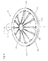
- Figure 4 shows a schematic perspective view of the elastic member 40 of the present embodiment.
- the elastic member 40 has the basic shape of a conical shell. It has an upper inner edge 401 and a lower outer edge 402. The upper inner edge 401 faces the armature 30 and the lower outer edge 402 resides against the valve body 10, specifically it resides against a first shoulder 101 of the cavity 110.
- the lower outer edge 402 is comprised by a ring section 420.
- the ring section has its geometric center on the longitudinal axis L, for example.
- a main plane of extension of the ring section 420 may be arranged perpendicular to the longitudinal axis L.
- the ring section 420 extends completely circumferentially around the valve needle 20.
- the elastic member 40 further has a plurality of beams 410, the beams emerging from the ring section 420 and extending to the upper inner edge 401.
- the beams 410 and the ring section 420 are formed as one piece in the present embodiment.
- the upper inner edge 401 is represented by first ends 4110 of the beams 410.
- the first ends 4110 are in particular free ends of the beams 410.
- Each beam 410 also has a second end 4120 with which it is anchored with the ring section 420 and merges with the ring section 420.
- the first end 4110 of each beam 410 is axially offset from the second end 4120 of the beam 410 by a distance d A .
- the beams 410 are arranged uniformly around the needle 20 in a top view along the longitudinal axis L.
- the beams 410 are evenly spaced in an angular direction A - i.e. clockwise or counter clockwise - around the longitudinal axis L.
- slots 430 are formed between each two neighboring beams 410.
- the elastic member 40 is operable to bias the armature 30 in a first axial direction D1 with respect to the valve body 10.
- the elastic member 40 resides on the first shoulder 101 of the valve body with its lower outer edge 402 and the first ends 4110 of the beams 410 are elastically deformed so that they are pressed against the armature 30 to exert a force in the first direction D1.
- the spring is pre-loaded - for example by means of a calibration element 140 of the valve assembly 1 - so that the spring 50 is operable to exert a force in the second direction D2 on the valve needle.
- the tip 210 of the needle In the closed state of the valve assembly 1 (see figure 2 ) the tip 210 of the needle is in a closing position. In the closing position, it resides against the valve seat 150 and is pressed against the valve seat 150 by means of the force exerted by the spring 50 on the needle 20 in the second direction D2.
- the armature 30 is pressed against the flange 220 of the valve needle 20 by means of the bias exerted on the armature 30 in the first direction D1 by the elastic member 40. In this way, the armature 30 transfers a force in the first direction D1 on the valve needle 20.
- valve assembly 1 When the valve assembly 1 is in the closed state, the magnitude of the force exerted by the spring 50 on the valve needle 20 in the second direction D2 exceeds the force transferred to the valve needle 20 in the first direction D1 by the armature 30 so that the tip 210 of the valve needle 20 is retained in its closing position residing against the valve seat 150. In this way, the injection nozzle 130 is sealed and fuel flow through the fuel outlet opening is prevented in the closed state of the valve assembly 1 as shown in figure 2 .
- valve assembly 1 In the following, a method for operating the valve assembly 1 is described in detail.
- the fuel injector may comprise an actuator assembly (not shown) provided for exerting an additional force in the first direction on the armature 30.
- the actuator assembly is an electromagnetic actuator assembly comprising a solenoid for generating a magnetic force as the additional force.
- Such actuator assemblies are in principle known to the person skilled in the art and will not be described here in further detail.
- the magnitude of the additional force is selected such that the bias of the elastic member of 40 and the additional force of the actuator assembly together are operable to move the armature 30 in the first direction to the opening position against the bias of the spring 50.
- the armature 30 moves from its first position in the first axial direction D1 with respect to the valve body 10 and takes the valve needle 20 with it in the first direction D1 with respect to the valve body 10 by means of the mechanical interaction between the armature 30 and the flange 220 - in the present embodiment by means of the form fitting connection of the armature 30 with the flange 220.
- valve needle 20 is axially moved out of the closing position, so that a gap is created between the tip 210 of the valve needle 20 and the valve seat 150.
- Fuel may flow from the fuel inlet opening 120 of the valve body 10 through the cavity 110 - and in particular through the recess of the needle 20 - and through the gap to the injection nozzle 130 and may be dispensed through the fuel outlet opening of injection nozzle 130.
- Movement of the armature 30 in the first direction may be limited by means of a second shoulder 102 of the valve body 10, for example.
- the armature 30 In the opened state of the valve assembly 1, the armature 30 may reside against the second shoulder 102, for example. In this way, the armature 30 may retain the valve needle 20 the opening position by means of the mechanical interaction with the flange 220.
- the actuator assembly may be turned off, so that the additional is no longer generated by the actuator assembly.
- the force of the spring 50 exerted on the valve needle 20 in the second direction D2 dominates and the spring 50 accelerates the needle 20 in the second direction D2.
- valve needle 20 takes the armature 30 with it in the second direction D2 towards the first position against the bias of the elastic member 40.
- the armature 30 in particular moves away from the second shoulder 102 in the present embodiment.
- the armature When moving in the second direction D2, the armature elastically deforms the beams 410 of the elastic member 40. Due to the deformation caused by the armature 30, the axial distance d A between the first and second ends 4110, 4120 of each beam 410 decreases.
- valve needle 20 and the armature 30 in the second direction D2 continues until the valve needle 20 reaches the closing position, where the tip 210 contacts the valve seat 120. Further movement of the valve needle 20 is then prevented by the mechanical interaction with the valve body 10 so that the valve needle 20 comes to a rest in the closing position.
- valve assembly 1 is configured in such way that the armature 30 is axially moveable in the second direction D2 with respect to the valve needle 20 and the valve body 10 from the first position.
- armature 30 decouples from the flange 220 and moves further in the second direction D2 against the bias of the elastic member 40.
- the bias of the elastic member 40 slows down the armature 30 until it comes to a rest in a second position shown in figure 3 . In the second position, the armature 30 is axially spaced from the flange 220 of the valve needle 20.
- the axial offset between the first and second ends 4110 and 4120 of the beams 410 is further reduced as compared to a configuration of the valve assembly 1 when the armature 30 is in the first position (as in figure 2 ).
- the beams 410 are deformed by the armature 30 in such way, that also a radial distance d R of the first ends 4110 from the valve needle 20 decreases when the armature 30 moves in the second direction D2.
- the first ends 4110 of the beams 410 are in direct contact with the needle, i.e. the radial distance d R equals 0.
- Another portion of the first kinetic energy of the armature 30 is dissipated. Specifically, when the armature 30 moves from the first position to the second position, the first ends 4110 of the beams move radially with respect to the surface of the armature 30 which they abut. This movement involves friction between the first ends 4110 and the armature 30 so that kinetic energy of the armature is dissipated. Further, energy is dissipated by friction between the first ends 4110 and the needle 20 when the beams 410 reach the surface of the needle 20.
- the beams 410 compress and displace fuel, for example towards the ring section 420, towards the first shoulder 101 of the valve body 10 and/or through the slots 430, which involves further dissipation of energy.
- the first kinetic energy which the armature 30 has when it initially reaches the first position during the closing event is only partially transformed into potential energy of the elastic member. Rather, a portion of the kinetic energy is dissipated.
- a certain deflection x L of the elastic member 40 in longitudinal direction L corresponds to a larger force F when deflecting the in the second direction D2 than when deflecting in the first direction D1. This means that the energy required to compress the elastic member 40 by a certain axial distance is higher than the energy which the elastic member 40 sets free on relaxation by the same distance.
- FIG 5 also shows that the load deflection curve is basically linear over almost the complete deflection range. This means that the spring force depends only on the deflection difference, but not on the absolute value of the deflection. In this way, the valve assembly 1 is particularly insensible to mounting or manufacturing tolerances.
- the armature 30 moves back in the first direction D1 with respect to the valve needle 20 and the valve body 10 towards the first position during the closing event of the valve assembly 1.
- the armature 30 hits the flange 220 of the valve needle 20 with a second kinetic energy thereby transferring energy to the valve needle 20 and exerting a certain force on the valve needle 20 in the first direction D1.
- the second kinetic energy Since some of the first kinetic energy has been dissipated during the movement from the first to the second position, the second kinetic energy has a smaller value than the first kinetic energy. Therefore, the energy transferred to the valve needle 20 during the armature-needle bounce is particularly low. In particular, it is insufficient to overcome the bias of the spring 50 in the second direction D2, so that the needle 20 does not move out of the closing position and the nozzle 130 remains sealed.
Claims (9)
- Ensemble de soupape (1) destiné à un injecteur de carburant, comprenant un corps de soupape (10) présentant un axe longitudinal (L), un pointeau de soupape (20), une armature (30) et un élément élastique (40), le pointeau de soupape (20) et l'armature (30) étant mobiles axialement par rapport au corps de soupape (10) dans une première direction (D1) et dans une seconde direction (D2), opposée à la première direction (D1), dans lequel:l'armature (30) est poussée dans la première direction (D1) au moyen de l'élément élastique (40),le pointeau (20), lorsqu'il se déplace dans la seconde direction (D2) vers une position de fermeture, est actionnable pour interagir mécaniquement avec l'armature (30) pour déplacer l'armature (30) dans la seconde direction (D2) jusqu'à une première position contre la poussée de l'élément élastique (40),l'armature (30) est mobile axialement par rapport au pointeau (20) de telle sorte que, lorsque le pointeau (20) se trouve dans la position de fermeture, l'armature (30) soit déplaçable depuis la première position plus loin dans la seconde direction (D2) jusqu'à une seconde position contre la poussée de l'élément élastique (40),l'élément élastique (40) comprend une pluralité de poutres (410), chaque poutre présentant une première extrémité (4110) et une seconde extrémité (4120) qui sont décalées axialement et radialement l'une par rapport à l'autre, etl'armature (30) est actionnable pour réduire le décalage axial (dA) entre la première extrémité (4110) et la seconde extrémité (4120) lors du déplacement de la première position vers la seconde position,caractérisé en ce que:l'élément élastique (40) entoure radialement le pointeau (20) et est formé de telle sorte que les premières extrémités (4110) des poutres (410) soient situées en face du pointeau (20) et soient agencées à une distance radiale (dR) du pointeau lorsque l'armature (30) se trouve dans la première position, etles poutres (410) sont élastiquement déformables de telle sorte que la distance radiale (dR) entre les premières extrémités (4110) et le pointeau (20) diminue lorsque l'armature (30) se déplace de la première vers la seconde position.
- Ensemble de soupape (1) selon la revendication 1, dans lequel au moins une des premières extrémités (4110) bute contre le pointeau (20) lorsque l'armature (30) se trouve dans la seconde position.
- Ensemble de soupape (1) selon l'une des revendications précédentes, dans lequel les poutres (410) sont agencées de façon uniformément espacée autour du pointeau (20) dans une vue du dessus le long de l'axe longitudinal (L).
- Ensemble de soupape (1) selon l'une des revendications précédentes, dans lequel l'élément élastique (40) présente la forme de base d'une coquille conique avec un bord intérieur supérieur (401) et un bord extérieur inférieur (402), le bord intérieur supérieur (401) faisant face à l'armature (30) et le bord extérieur inférieur (402) résidant contre le corps de soupape (10), ou vice versa.
- Ensemble de soupape (1) selon la revendication 4, dans lequel le bord intérieur supérieur (401) est discontinu et est formé par les premières extrémités (4110) des poutres (410).
- Ensemble de soupape (1) selon la revendication 5, dans lequel l'élément élastique (40) présente une section annulaire circonférentielle (420), la section annulaire (420) comprend le bord extérieur inférieur (402), et les poutres (410) sont ancrées à la section annulaire (420) à leurs secondes extrémités (4120).
- Ensemble de soupape (1) selon l'une des revendications précédentes, dans lequel l'élément élastique (40) est conçu de manière à pousser l'armature (30) avec une force dans la première direction (D1), la force étant indépendante d'une position axiale de l'armature (30).
- Ensemble de soupape (1) selon l'une des revendications précédentes, dans lequel l'ensemble de soupape (1) est configuré de manière à dissiper l'énergie cinétique de l'armature (30) lorsque l'armature se déplace de la première position en direction de la seconde position au moyen d'une interaction mécanique de l'élément élastique (40) avec l'armature (30) et/ou le pointeau (20) et/ou le carburant.
- Injecteur de carburant comprenant un ensemble de soupape (1) selon l'une des revendications précédentes.
Priority Applications (1)
| Application Number | Priority Date | Filing Date | Title |
|---|---|---|---|
| EP12183513.6A EP2706221B1 (fr) | 2012-09-07 | 2012-09-07 | Ensemble de soupape destiné à un injecteur de carburant et injecteur de carburant |
Applications Claiming Priority (1)
| Application Number | Priority Date | Filing Date | Title |
|---|---|---|---|
| EP12183513.6A EP2706221B1 (fr) | 2012-09-07 | 2012-09-07 | Ensemble de soupape destiné à un injecteur de carburant et injecteur de carburant |
Publications (2)
| Publication Number | Publication Date |
|---|---|
| EP2706221A1 EP2706221A1 (fr) | 2014-03-12 |
| EP2706221B1 true EP2706221B1 (fr) | 2016-07-13 |
Family
ID=46880987
Family Applications (1)
| Application Number | Title | Priority Date | Filing Date |
|---|---|---|---|
| EP12183513.6A Not-in-force EP2706221B1 (fr) | 2012-09-07 | 2012-09-07 | Ensemble de soupape destiné à un injecteur de carburant et injecteur de carburant |
Country Status (1)
| Country | Link |
|---|---|
| EP (1) | EP2706221B1 (fr) |
Families Citing this family (4)
| Publication number | Priority date | Publication date | Assignee | Title |
|---|---|---|---|---|
| EP2896812B1 (fr) | 2014-01-16 | 2017-09-06 | Continental Automotive GmbH | Injecteur à carburant |
| US9341154B2 (en) | 2014-04-10 | 2016-05-17 | Continental Automotive Gmbh | Valve assembly for a fuel injector and fuel injector |
| DE102015215537A1 (de) * | 2015-08-14 | 2017-02-16 | Robert Bosch Gmbh | Ventil zum Zumessen eines Fluids |
| EP3153700A1 (fr) * | 2015-10-08 | 2017-04-12 | Continental Automotive GmbH | Ensemble de soupape pour soupape d'injection, une telle soupape et procédé pour assembler ladite soupape |
Family Cites Families (4)
| Publication number | Priority date | Publication date | Assignee | Title |
|---|---|---|---|---|
| IT1289794B1 (it) * | 1996-12-23 | 1998-10-16 | Elasis Sistema Ricerca Fiat | Perfezionamenti ad una valvola di dosaggio a comando elettromagnetico per un iniettore di combustibile. |
| DE19927900A1 (de) * | 1999-06-18 | 2000-12-21 | Bosch Gmbh Robert | Brennstoffeinspritzventil |
| IT1310757B1 (it) * | 1999-11-30 | 2002-02-22 | Fiat Ricerche | Valvola di dosaggio a comando elettromagnetico per un iniettore dicombustibile |
| EP1845254A1 (fr) * | 2006-04-11 | 2007-10-17 | Siemens Aktiengesellschaft | Ensemble de soupape |
-
2012
- 2012-09-07 EP EP12183513.6A patent/EP2706221B1/fr not_active Not-in-force
Also Published As
| Publication number | Publication date |
|---|---|
| EP2706221A1 (fr) | 2014-03-12 |
Similar Documents
| Publication | Publication Date | Title |
|---|---|---|
| EP1783356B1 (fr) | Soupape d'injection de carburant | |
| EP2535552B1 (fr) | Ensemble de soupape pour soupape d'injection et soupape d'injection | |
| EP2796703B1 (fr) | Ensemble de soupape pour soupape d'injection et soupape d'injection | |
| US9359984B2 (en) | Valve assembly for an injection valve and injection valve | |
| EP2706221B1 (fr) | Ensemble de soupape destiné à un injecteur de carburant et injecteur de carburant | |
| KR102087467B1 (ko) | 분사 밸브를 위한 밸브 조립체 및 분사 밸브 | |
| EP2851551B1 (fr) | Soupape d'injection de fluide | |
| EP2888470B1 (fr) | Ensemble de soupape pour soupape d'injection et soupape d'injection | |
| US9341154B2 (en) | Valve assembly for a fuel injector and fuel injector | |
| US10309360B2 (en) | Valve assembly for an injection valve and injection valve | |
| KR102139895B1 (ko) | 자기 링 요소를 갖는 분사 밸브 | |
| CN106795843B (zh) | 用于喷射流体的喷射器 | |
| EP2846032B1 (fr) | Soupape d'injection de fluide | |
| CN111720855A (zh) | 用于涡轮发动机的燃料喷射器 | |
| CN203906156U (zh) | 用于燃料喷射器的阀组件和燃料喷射器 | |
| EP3058215B1 (fr) | Soupape d'injection | |
| EP2439400A1 (fr) | Ensemble de soupape pour soupape d'injection et soupape d'injection | |
| EP2241743B1 (fr) | Ensemble de soupape pour soupape d'injection et soupape d'injection | |
| EP2703633A1 (fr) | Ensemble de soupape pour soupape d'injection et soupape d'injection |
Legal Events
| Date | Code | Title | Description |
|---|---|---|---|
| PUAI | Public reference made under article 153(3) epc to a published international application that has entered the european phase |
Free format text: ORIGINAL CODE: 0009012 |
|
| AK | Designated contracting states |
Kind code of ref document: A1 Designated state(s): AL AT BE BG CH CY CZ DE DK EE ES FI FR GB GR HR HU IE IS IT LI LT LU LV MC MK MT NL NO PL PT RO RS SE SI SK SM TR |
|
| AX | Request for extension of the european patent |
Extension state: BA ME |
|
| 17P | Request for examination filed |
Effective date: 20140912 |
|
| RBV | Designated contracting states (corrected) |
Designated state(s): AL AT BE BG CH CY CZ DE DK EE ES FI FR GB GR HR HU IE IS IT LI LT LU LV MC MK MT NL NO PL PT RO RS SE SI SK SM TR |
|
| GRAP | Despatch of communication of intention to grant a patent |
Free format text: ORIGINAL CODE: EPIDOSNIGR1 |
|
| RIC1 | Information provided on ipc code assigned before grant |
Ipc: F02M 63/00 20060101ALI20160203BHEP Ipc: F16F 1/32 20060101ALI20160203BHEP Ipc: F02M 61/20 20060101ALI20160203BHEP Ipc: F02M 51/06 20060101AFI20160203BHEP |
|
| INTG | Intention to grant announced |
Effective date: 20160226 |
|
| GRAS | Grant fee paid |
Free format text: ORIGINAL CODE: EPIDOSNIGR3 |
|
| GRAA | (expected) grant |
Free format text: ORIGINAL CODE: 0009210 |
|
| AK | Designated contracting states |
Kind code of ref document: B1 Designated state(s): AL AT BE BG CH CY CZ DE DK EE ES FI FR GB GR HR HU IE IS IT LI LT LU LV MC MK MT NL NO PL PT RO RS SE SI SK SM TR |
|
| REG | Reference to a national code |
Ref country code: GB Ref legal event code: FG4D |
|
| REG | Reference to a national code |
Ref country code: AT Ref legal event code: REF Ref document number: 812545 Country of ref document: AT Kind code of ref document: T Effective date: 20160715 Ref country code: CH Ref legal event code: EP |
|
| REG | Reference to a national code |
Ref country code: IE Ref legal event code: FG4D |
|
| REG | Reference to a national code |
Ref country code: DE Ref legal event code: R096 Ref document number: 602012020370 Country of ref document: DE |
|
| REG | Reference to a national code |
Ref country code: FR Ref legal event code: PLFP Year of fee payment: 5 |
|
| REG | Reference to a national code |
Ref country code: LT Ref legal event code: MG4D |
|
| REG | Reference to a national code |
Ref country code: NL Ref legal event code: MP Effective date: 20160713 |
|
| REG | Reference to a national code |
Ref country code: AT Ref legal event code: MK05 Ref document number: 812545 Country of ref document: AT Kind code of ref document: T Effective date: 20160713 |
|
| PG25 | Lapsed in a contracting state [announced via postgrant information from national office to epo] |
Ref country code: FI Free format text: LAPSE BECAUSE OF FAILURE TO SUBMIT A TRANSLATION OF THE DESCRIPTION OR TO PAY THE FEE WITHIN THE PRESCRIBED TIME-LIMIT Effective date: 20160713 Ref country code: NL Free format text: LAPSE BECAUSE OF FAILURE TO SUBMIT A TRANSLATION OF THE DESCRIPTION OR TO PAY THE FEE WITHIN THE PRESCRIBED TIME-LIMIT Effective date: 20160713 Ref country code: HR Free format text: LAPSE BECAUSE OF FAILURE TO SUBMIT A TRANSLATION OF THE DESCRIPTION OR TO PAY THE FEE WITHIN THE PRESCRIBED TIME-LIMIT Effective date: 20160713 Ref country code: NO Free format text: LAPSE BECAUSE OF FAILURE TO SUBMIT A TRANSLATION OF THE DESCRIPTION OR TO PAY THE FEE WITHIN THE PRESCRIBED TIME-LIMIT Effective date: 20161013 Ref country code: RS Free format text: LAPSE BECAUSE OF FAILURE TO SUBMIT A TRANSLATION OF THE DESCRIPTION OR TO PAY THE FEE WITHIN THE PRESCRIBED TIME-LIMIT Effective date: 20160713 Ref country code: LT Free format text: LAPSE BECAUSE OF FAILURE TO SUBMIT A TRANSLATION OF THE DESCRIPTION OR TO PAY THE FEE WITHIN THE PRESCRIBED TIME-LIMIT Effective date: 20160713 Ref country code: IS Free format text: LAPSE BECAUSE OF FAILURE TO SUBMIT A TRANSLATION OF THE DESCRIPTION OR TO PAY THE FEE WITHIN THE PRESCRIBED TIME-LIMIT Effective date: 20161113 |
|
| PG25 | Lapsed in a contracting state [announced via postgrant information from national office to epo] |
Ref country code: PT Free format text: LAPSE BECAUSE OF FAILURE TO SUBMIT A TRANSLATION OF THE DESCRIPTION OR TO PAY THE FEE WITHIN THE PRESCRIBED TIME-LIMIT Effective date: 20161114 Ref country code: SE Free format text: LAPSE BECAUSE OF FAILURE TO SUBMIT A TRANSLATION OF THE DESCRIPTION OR TO PAY THE FEE WITHIN THE PRESCRIBED TIME-LIMIT Effective date: 20160713 Ref country code: ES Free format text: LAPSE BECAUSE OF FAILURE TO SUBMIT A TRANSLATION OF THE DESCRIPTION OR TO PAY THE FEE WITHIN THE PRESCRIBED TIME-LIMIT Effective date: 20160713 Ref country code: AT Free format text: LAPSE BECAUSE OF FAILURE TO SUBMIT A TRANSLATION OF THE DESCRIPTION OR TO PAY THE FEE WITHIN THE PRESCRIBED TIME-LIMIT Effective date: 20160713 Ref country code: BE Free format text: LAPSE BECAUSE OF NON-PAYMENT OF DUE FEES Effective date: 20160713 Ref country code: LV Free format text: LAPSE BECAUSE OF FAILURE TO SUBMIT A TRANSLATION OF THE DESCRIPTION OR TO PAY THE FEE WITHIN THE PRESCRIBED TIME-LIMIT Effective date: 20160713 Ref country code: GR Free format text: LAPSE BECAUSE OF FAILURE TO SUBMIT A TRANSLATION OF THE DESCRIPTION OR TO PAY THE FEE WITHIN THE PRESCRIBED TIME-LIMIT Effective date: 20161014 Ref country code: PL Free format text: LAPSE BECAUSE OF FAILURE TO SUBMIT A TRANSLATION OF THE DESCRIPTION OR TO PAY THE FEE WITHIN THE PRESCRIBED TIME-LIMIT Effective date: 20160713 |
|
| REG | Reference to a national code |
Ref country code: DE Ref legal event code: R097 Ref document number: 602012020370 Country of ref document: DE |
|
| PG25 | Lapsed in a contracting state [announced via postgrant information from national office to epo] |
Ref country code: MC Free format text: LAPSE BECAUSE OF FAILURE TO SUBMIT A TRANSLATION OF THE DESCRIPTION OR TO PAY THE FEE WITHIN THE PRESCRIBED TIME-LIMIT Effective date: 20160713 Ref country code: RO Free format text: LAPSE BECAUSE OF FAILURE TO SUBMIT A TRANSLATION OF THE DESCRIPTION OR TO PAY THE FEE WITHIN THE PRESCRIBED TIME-LIMIT Effective date: 20160713 Ref country code: EE Free format text: LAPSE BECAUSE OF FAILURE TO SUBMIT A TRANSLATION OF THE DESCRIPTION OR TO PAY THE FEE WITHIN THE PRESCRIBED TIME-LIMIT Effective date: 20160713 |
|
| REG | Reference to a national code |
Ref country code: CH Ref legal event code: PL |
|
| PLBE | No opposition filed within time limit |
Free format text: ORIGINAL CODE: 0009261 |
|
| STAA | Information on the status of an ep patent application or granted ep patent |
Free format text: STATUS: NO OPPOSITION FILED WITHIN TIME LIMIT |
|
| PG25 | Lapsed in a contracting state [announced via postgrant information from national office to epo] |
Ref country code: CZ Free format text: LAPSE BECAUSE OF FAILURE TO SUBMIT A TRANSLATION OF THE DESCRIPTION OR TO PAY THE FEE WITHIN THE PRESCRIBED TIME-LIMIT Effective date: 20160713 Ref country code: SK Free format text: LAPSE BECAUSE OF FAILURE TO SUBMIT A TRANSLATION OF THE DESCRIPTION OR TO PAY THE FEE WITHIN THE PRESCRIBED TIME-LIMIT Effective date: 20160713 Ref country code: BG Free format text: LAPSE BECAUSE OF FAILURE TO SUBMIT A TRANSLATION OF THE DESCRIPTION OR TO PAY THE FEE WITHIN THE PRESCRIBED TIME-LIMIT Effective date: 20161013 Ref country code: DK Free format text: LAPSE BECAUSE OF FAILURE TO SUBMIT A TRANSLATION OF THE DESCRIPTION OR TO PAY THE FEE WITHIN THE PRESCRIBED TIME-LIMIT Effective date: 20160713 Ref country code: SM Free format text: LAPSE BECAUSE OF FAILURE TO SUBMIT A TRANSLATION OF THE DESCRIPTION OR TO PAY THE FEE WITHIN THE PRESCRIBED TIME-LIMIT Effective date: 20160713 |
|
| 26N | No opposition filed |
Effective date: 20170418 |
|
| REG | Reference to a national code |
Ref country code: IE Ref legal event code: MM4A |
|
| PG25 | Lapsed in a contracting state [announced via postgrant information from national office to epo] |
Ref country code: LI Free format text: LAPSE BECAUSE OF NON-PAYMENT OF DUE FEES Effective date: 20160930 Ref country code: IE Free format text: LAPSE BECAUSE OF NON-PAYMENT OF DUE FEES Effective date: 20160907 Ref country code: CH Free format text: LAPSE BECAUSE OF NON-PAYMENT OF DUE FEES Effective date: 20160930 |
|
| PG25 | Lapsed in a contracting state [announced via postgrant information from national office to epo] |
Ref country code: SI Free format text: LAPSE BECAUSE OF FAILURE TO SUBMIT A TRANSLATION OF THE DESCRIPTION OR TO PAY THE FEE WITHIN THE PRESCRIBED TIME-LIMIT Effective date: 20160713 Ref country code: LU Free format text: LAPSE BECAUSE OF NON-PAYMENT OF DUE FEES Effective date: 20160907 |
|
| REG | Reference to a national code |
Ref country code: FR Ref legal event code: PLFP Year of fee payment: 6 |
|
| PG25 | Lapsed in a contracting state [announced via postgrant information from national office to epo] |
Ref country code: CY Free format text: LAPSE BECAUSE OF FAILURE TO SUBMIT A TRANSLATION OF THE DESCRIPTION OR TO PAY THE FEE WITHIN THE PRESCRIBED TIME-LIMIT Effective date: 20160713 Ref country code: HU Free format text: LAPSE BECAUSE OF FAILURE TO SUBMIT A TRANSLATION OF THE DESCRIPTION OR TO PAY THE FEE WITHIN THE PRESCRIBED TIME-LIMIT; INVALID AB INITIO Effective date: 20120907 |
|
| PG25 | Lapsed in a contracting state [announced via postgrant information from national office to epo] |
Ref country code: MT Free format text: LAPSE BECAUSE OF NON-PAYMENT OF DUE FEES Effective date: 20160930 Ref country code: MK Free format text: LAPSE BECAUSE OF FAILURE TO SUBMIT A TRANSLATION OF THE DESCRIPTION OR TO PAY THE FEE WITHIN THE PRESCRIBED TIME-LIMIT Effective date: 20160713 |
|
| REG | Reference to a national code |
Ref country code: FR Ref legal event code: PLFP Year of fee payment: 7 |
|
| PG25 | Lapsed in a contracting state [announced via postgrant information from national office to epo] |
Ref country code: AL Free format text: LAPSE BECAUSE OF FAILURE TO SUBMIT A TRANSLATION OF THE DESCRIPTION OR TO PAY THE FEE WITHIN THE PRESCRIBED TIME-LIMIT Effective date: 20160713 Ref country code: TR Free format text: LAPSE BECAUSE OF FAILURE TO SUBMIT A TRANSLATION OF THE DESCRIPTION OR TO PAY THE FEE WITHIN THE PRESCRIBED TIME-LIMIT Effective date: 20160713 |
|
| PGFP | Annual fee paid to national office [announced via postgrant information from national office to epo] |
Ref country code: IT Payment date: 20180925 Year of fee payment: 7 Ref country code: FR Payment date: 20180925 Year of fee payment: 7 |
|
| PGFP | Annual fee paid to national office [announced via postgrant information from national office to epo] |
Ref country code: GB Payment date: 20180919 Year of fee payment: 7 |
|
| PGFP | Annual fee paid to national office [announced via postgrant information from national office to epo] |
Ref country code: DE Payment date: 20180930 Year of fee payment: 7 |
|
| REG | Reference to a national code |
Ref country code: DE Ref legal event code: R119 Ref document number: 602012020370 Country of ref document: DE |
|
| PG25 | Lapsed in a contracting state [announced via postgrant information from national office to epo] |
Ref country code: DE Free format text: LAPSE BECAUSE OF NON-PAYMENT OF DUE FEES Effective date: 20200401 |
|
| PG25 | Lapsed in a contracting state [announced via postgrant information from national office to epo] |
Ref country code: IT Free format text: LAPSE BECAUSE OF NON-PAYMENT OF DUE FEES Effective date: 20190907 |
|
| GBPC | Gb: european patent ceased through non-payment of renewal fee |
Effective date: 20190907 |
|
| PG25 | Lapsed in a contracting state [announced via postgrant information from national office to epo] |
Ref country code: FR Free format text: LAPSE BECAUSE OF NON-PAYMENT OF DUE FEES Effective date: 20190930 Ref country code: GB Free format text: LAPSE BECAUSE OF NON-PAYMENT OF DUE FEES Effective date: 20190907 |