EP2705409B1 - Pipeline-analysesystem und sanierungsmethode - Google Patents
Pipeline-analysesystem und sanierungsmethode Download PDFInfo
- Publication number
- EP2705409B1 EP2705409B1 EP12779531.8A EP12779531A EP2705409B1 EP 2705409 B1 EP2705409 B1 EP 2705409B1 EP 12779531 A EP12779531 A EP 12779531A EP 2705409 B1 EP2705409 B1 EP 2705409B1
- Authority
- EP
- European Patent Office
- Prior art keywords
- pipeline
- infrastructure
- data
- unit
- data collection
- Prior art date
- Legal status (The legal status is an assumption and is not a legal conclusion. Google has not performed a legal analysis and makes no representation as to the accuracy of the status listed.)
- Active
Links
Images


Classifications
-
- G—PHYSICS
- G01—MEASURING; TESTING
- G01N—INVESTIGATING OR ANALYSING MATERIALS BY DETERMINING THEIR CHEMICAL OR PHYSICAL PROPERTIES
- G01N17/00—Investigating resistance of materials to the weather, to corrosion, or to light
- G01N17/02—Electrochemical measuring systems for weathering, corrosion or corrosion-protection measurement
-
- F—MECHANICAL ENGINEERING; LIGHTING; HEATING; WEAPONS; BLASTING
- F17—STORING OR DISTRIBUTING GASES OR LIQUIDS
- F17D—PIPE-LINE SYSTEMS; PIPE-LINES
- F17D3/00—Arrangements for supervising or controlling working operations
- F17D3/01—Arrangements for supervising or controlling working operations for controlling, signalling, or supervising the conveyance of a product
-
- F—MECHANICAL ENGINEERING; LIGHTING; HEATING; WEAPONS; BLASTING
- F16—ENGINEERING ELEMENTS AND UNITS; GENERAL MEASURES FOR PRODUCING AND MAINTAINING EFFECTIVE FUNCTIONING OF MACHINES OR INSTALLATIONS; THERMAL INSULATION IN GENERAL
- F16L—PIPES; JOINTS OR FITTINGS FOR PIPES; SUPPORTS FOR PIPES, CABLES OR PROTECTIVE TUBING; MEANS FOR THERMAL INSULATION IN GENERAL
- F16L58/00—Protection of pipes or pipe fittings against corrosion or incrustation
-
- F—MECHANICAL ENGINEERING; LIGHTING; HEATING; WEAPONS; BLASTING
- F17—STORING OR DISTRIBUTING GASES OR LIQUIDS
- F17D—PIPE-LINE SYSTEMS; PIPE-LINES
- F17D5/00—Protection or supervision of installations
-
- F—MECHANICAL ENGINEERING; LIGHTING; HEATING; WEAPONS; BLASTING
- F17—STORING OR DISTRIBUTING GASES OR LIQUIDS
- F17D—PIPE-LINE SYSTEMS; PIPE-LINES
- F17D5/00—Protection or supervision of installations
- F17D5/02—Preventing, monitoring, or locating loss
- F17D5/06—Preventing, monitoring, or locating loss using electric or acoustic means
-
- G—PHYSICS
- G01—MEASURING; TESTING
- G01N—INVESTIGATING OR ANALYSING MATERIALS BY DETERMINING THEIR CHEMICAL OR PHYSICAL PROPERTIES
- G01N17/00—Investigating resistance of materials to the weather, to corrosion, or to light
-
- G—PHYSICS
- G06—COMPUTING OR CALCULATING; COUNTING
- G06Q—INFORMATION AND COMMUNICATION TECHNOLOGY [ICT] SPECIALLY ADAPTED FOR ADMINISTRATIVE, COMMERCIAL, FINANCIAL, MANAGERIAL OR SUPERVISORY PURPOSES; SYSTEMS OR METHODS SPECIALLY ADAPTED FOR ADMINISTRATIVE, COMMERCIAL, FINANCIAL, MANAGERIAL OR SUPERVISORY PURPOSES, NOT OTHERWISE PROVIDED FOR
- G06Q10/00—Administration; Management
- G06Q10/20—Administration of product repair or maintenance
-
- Y—GENERAL TAGGING OF NEW TECHNOLOGICAL DEVELOPMENTS; GENERAL TAGGING OF CROSS-SECTIONAL TECHNOLOGIES SPANNING OVER SEVERAL SECTIONS OF THE IPC; TECHNICAL SUBJECTS COVERED BY FORMER USPC CROSS-REFERENCE ART COLLECTIONS [XRACs] AND DIGESTS
- Y04—INFORMATION OR COMMUNICATION TECHNOLOGIES HAVING AN IMPACT ON OTHER TECHNOLOGY AREAS
- Y04S—SYSTEMS INTEGRATING TECHNOLOGIES RELATED TO POWER NETWORK OPERATION, COMMUNICATION OR INFORMATION TECHNOLOGIES FOR IMPROVING THE ELECTRICAL POWER GENERATION, TRANSMISSION, DISTRIBUTION, MANAGEMENT OR USAGE, i.e. SMART GRIDS
- Y04S10/00—Systems supporting electrical power generation, transmission or distribution
- Y04S10/50—Systems or methods supporting the power network operation or management, involving a certain degree of interaction with the load-side end user applications
Definitions
- Energy infrastructure such as transmission towers and pipelines may be installed to provide energy and other services to houses, buildings, facilities and other structures. Once installed it is difficult to determine if there is a maintenance problem with the buried infrastructure and whether a maintenance and/or remediation operation should be performed on the infrastructure, or portions thereof. Therefore a need exists to efficiently perform testing, inspection, and analysis of buried energy infrastructure.
- US Patent Application 2006/0129338 discloses a pipeline analysis system using in-line pipe inspection devices to inspect pipeline segments corresponding to high concern areas and assessing risks of pipeline failures.
- the present invention provides therefore a pipeline analysis system and an infrastructure remediation method using said system according to claims 1 and 6, respectively.
- fluids shall include fluids and gases.
- Embodiments may take the form of an entirely hardware embodiment, an entirely software embodiment (including firmware, resident software, micro-code, etc.) or an embodiment combining software and hardware aspects that may all generally be referred to herein as a "circuit," “module” or “system.”
- embodiments of the inventive subject matter may take the form of a computer program product embodied in any tangible medium of expression having computer usable program code embodied in the medium.
- the described embodiments may be provided as a computer program product, or software, that may include a machine-readable medium having stored thereon instructions, which may be used to program a computer system (or other electronic device(s)) to perform a process according to embodiments, whether presently described or not, since every conceivable variation is not enumerated herein.
- a machine readable medium includes any mechanism for storing or transmitting information in a form (e.g., software, processing application) readable by a machine (e.g., a computer).
- the machine-readable medium may include, but is not limited to, magnetic storage medium (e.g., floppy diskette); optical storage medium (e.g., CD-ROM); magneto-optical storage medium; read only memory (ROM); random access memory (RAM); erasable programmable memory (e.g., EPROM and EEPROM); flash memory; or other types of medium suitable for storing electronic instructions.
- embodiments may be embodied in an electrical, optical, acoustical or other form of propagated signal (e.g., carrier waves, infrared signals, digital signals, etc.), or wireline, wireless, or other communications medium.
- Computer program code for carrying out operations of the embodiments may be written in any combination of one or more programming languages, including an object oriented programming language such as Java, Smalltalk, C++ or the like and conventional procedural programming languages, such as the "C" programming language or similar programming languages.
- the program code may execute entirely on a user's computer, partly on the user's computer, as a stand-alone software package, partly on the user's computer and partly on a remote computer or entirely on the remote computer or server.
- the remote computer may be connected to the user's computer through any type of network, including a local area network (LAN), a personal area network (PAN), or a wide area network (WAN), or the connection may be made to an external computer (for example, through the Internet using an Internet Service Provider).
- LAN local area network
- PAN personal area network
- WAN wide area network
- Internet Service Provider for example, AT&T, MCI, Sprint, EarthLink, MSN, GTE, etc.
- FIG. 1 depicts a schematic view of an infrastructure analysis system 100.
- the infrastructure analysis system 100 may be for analyzing conditions and/or damage to a power infrastructure 102.
- the infrastructure analysis system 100 is a plurality of transmission towers 104 for supporting a transmission line 106.
- the infrastructure analysis system 100 may have the power infrastructure 102, one or more field workers 108, one or more data collection tools 110, one or more data input devices 112, a communication network 114 and an infrastructure unit 116.
- the infrastructure analysis system 100 may have one or more analysis workers 118 at a service company 120.
- the service company 120 may be hired to perform analysis, maintenance, remediation, and/or construction on the power infrastructure 102.
- the infrastructure analysis system 100 may communicate with a client company 122.
- the service company 120 and/or the client company 122 may have any number of computers 124 which may have the infrastructure unit 116 therein.
- the field worker may have a computer 124.
- the transmission towers 104 may be any suitable transmission towers or transmission line supports.
- the transmission towers 104 may have one or more legs 126 and one or more tower footings 128.
- the tower footings 128 may secure into a soil 130(A-D) for securing the transmission tower 104 in place.
- the tower footings 128 may secure to the legs 126 or be integral therewith.
- the tower footing 128 may be steel member foundations having multiple components as shown in Figures 2A and 2B .
- the soil 130A-D at each of the transmission towers 104 may be similar or may vary at each transmission tower 104 or at each leg 126.
- the field worker 108 may be any suitable worker (such as a technician or an engineer) that is sent to the power infrastructure 102 to collect data during a data collection phase of the project.
- the field worker 108 may input the collected data directly into the one or more data input devices 112 and/or the computer 124 as the data is collected in the field.
- the one or more data collection tools 110 may communicate directly with the one or more data input devices 112 and/or the computer 124 or the field worker 108 may input the collected data manually.
- the one or more data input devices 112 and/or the computer 124 may send the data to the infrastructure unit(s) 116 located about the infrastructure analysis system 100.
- the field worker 108 may collect data for one of the transmission towers 104 then move to the next transmission towers 104, or selected transmission towers 104, in the power infrastructure 102. Further, the field worker 108 may collect data from only a select few of the transmission towers 104 and then use the infrastructure analysis system 100 to predict the conditions of the other transmission towers 104 and formulate a project plan, or implementation plan.
- the communication network 114 allows for communication about the infrastructure analysis system 100 and may be any suitable network including those described herein.
- the field worker 108 may collect data from all, or portions of, the power infrastructure 102 during a data gathering phase of the project. During the data gathering phase the field worker 108 may use the data collection tools 110 and/or observation at the power infrastructure 102.
- the data collection may take place during routine structure surveys including, but not limited to, annual surveys, scheduled maintenance, specific service calls and the like.
- the data collection may include identifying candidate areas for detailed surveys, measuring DC and AC structure potential to a Copper-Copper Sulfate Electrode (CSE).
- the electrochemical potential of a structure (for example the transmission tower) may be related to corrosion activity. For example the potential of carbon steel may be -0.550V to -0.800V (CSE).
- CSE Copper-Copper Sulfate Electrode
- the potential of newer structures is more electronegative.
- the potential of coated structures may be more electronegative.
- the potential of steel embedded in concrete 0.250 to -0.550V(CSE).
- the potential of galvanized structures -0.800V (CSE) and the potential of copper is -0.200V to -0.300V(CSE). Therefore the data collection may include measuring the potential of the tower to soil as shown in Figure 3A .
- the data collection may include, but is not limited to, a Wenner four pin soil resistivity measurement.
- the soil resistivity at each transmission tower 104 (as shown in Figure 1 ) may be measured using the Wenner four pin method in one location to various depths representing the depth of the structure, e.g. a depth of thirty, sixty one and ninety one centimetres (one, two and three feet).
- the data collection may include, but is not limited to, electrochemical and physical measurements.
- the assessment protocol of the transmission towers 104 may use a combination of electrochemical and physical measurements that were used to determine the propensity of the environmental causes for corrosion.
- These data collection methods may include, but are not limited to, AC voltage measurements, DC voltage measurements, LPR corrosion rate measurement (to determine the relative corrosion rate of soil), soil pH, soil resistivity, soil chemistry, redox (oxidation-reduction) potential, coating thickness, degradation documentation, nondestructive testing or examination (which are commonly referred to as "NDE" examination) of a structure (e.g. tower, pipeline, etc.) and the like.
- the AC voltage measurement may include a high voltage safety test which is first conducted to verify that the structure is safe to work near. An AC voltage test may then be made at each leg 126 of the transmission tower 104 (as shown in Figure 1 ). The AC voltage test may be performed by placing a copper-copper sulfate reference electrode thirty to forty six centimetres (twelve to eighteen inches) from the tower leg. The half cell may be connected to a Fluke multi-meter common terminal and the tower may be connected to a positive terminal of the voltmeter as shown in Figure 3A . A fifteen volt maximum criterion may be used to determine if there is a shock hazard.
- the DC voltage measurement may be performed at each leg 126 of the transmission tower 104 (as shown in Figure 1 ) in the same manner as the AC measurements except the voltmeter may be set to measure DC voltage.
- the electro-chemical potential of galvanized steel is expected to be more negative than -0.750 volts (CSE) when the galvanizing is new and intact and not adversely affected by high concentrations of carbonates and nitrates in the soil. These compounds may passivate the zinc and drive the electro-chemical potential in the positive direction.
- the electro-chemical potential of unprotected bare carbon steel in soils is expected to be -0.650 volts to -0.750 volts (CSE) when first exposed and will migrate in the positive direction over time as corrosion progresses.
- a potential of -0.550 volts (CSE) is considered a typical free corrosion potential of carbon steel that has experienced some corrosion. Carbon steel when bonded to copper may exhibit potentials that are in the range of -0.400 volts (CSE).
- Soil resistivity measurements may be taken for various depths below ground level to assess the potential corrosivity of the soil surrounding the buried portion of the structure.
- Soil resistivity is the inverse of conductivity and may provide an indication of soil corrosivity.
- Figure 4A depicts a general characterization of soil corrosivity based on soil resistivity measurements. The data shown in figure 4A indicates that there are areas of higher soil resistivity values that are typical of the elevated terrain and soil conditions.
- the soil pH at each tower leg was measured and recorded using a Fluke multi-meter connected to a saturated copper-copper sulfate reference electrode (- negative terminal lead) and an antimony reference cell (+ terminal lead).
- a pH of 7 is considered neutral and indicates that the number of hydrogen ions in solution is equal to the number of hydroxyl ions in solution.
- the relationship of pH to the impact of corrosion for steel and zinc is shown in Figures 4B and 4C .
- the redox potential was measured and recorded for each tower.
- the redox potentials are an indication of the oxidation-reduction potential of the soil environment. They are typically used to determine the propensity of microbial activity in the soil that may contribute to microbiologically induced corrosion (MIC) and in particular, sulfate reducing bacterial induced corrosion. Values that are less than 150 millivolts indicate a moderate tendency of MIC while negative values indicate a severe tendency of MIC.
- MIC microbiologically induced corrosion
- Coating thickness was measured and recorded using an electronic coating film thickness gauge to test the thickness of the zinc coating at two locations on each tower leg. One location was thirty centimetres (12 inches) above the ground level and the other was thirty centimetres (12 inches) below the ground level.
- the worker and/or the data collection tools may input the results of the data collection into the data input device 112 and/or the computer 124.
- the data collection phase may determine any number of data elements for each of the transmission towers 104, the tower footings 128, and/or the legs 126. In one example up to sixteen data elements were collected to assist the prediction of the likelihood of corrosion and to measure the actual corrosion on the transmission towers 104.
- the data elements may include, but are not limited to, GPS coordinates, AC tower to soil potential, DC tower to soil potential, LPR corrosion rate measurement, visual corrosion pattern, section loss length, maximum pit depth, soil chemistry (chlorides, sulfates, passivation including carbonates bicarbonates and nitrates, antimony cell pH, redox potential, coating thickness 30 centimetres (12") above soil, coating thickness 30 centimetres (12") below the soil, soil resistivity, soil resistivity variation, soil type, topography, vegetation, photography, comments, electrochemical factor(s) (e.g. structure potential, structure potential variation, and corrosion rate), stray current interference factor(s), design factor(s) (e.g. type of structure and copper ground), visual corrosion factor(s) (e.g.
- cathodic protection factor(s) e.g. applied cathodic protection and protection level
- the data elements may be selected on the basis of their relevance to the likelihood of corrosion in the localized area of the individual towers and/or actual wall loss.
- the collected data and/or the data elements for each of the transmission towers 104 surveyed may be sent to the infrastructure unit(s) 116 via the data input unit 108, the computer 124 used by the field worker 108, and/or entered by the worker 118 at the service company 120.
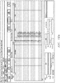
- the worker 118 at the service company 120 may input the data into the infrastructure unit 116 from data collected in a data collection sheet 600 as shown in Figure 6 .
- FIG. 7 depicts a block diagram of the infrastructure unit 116 according to an example outside the scope of the present invention.
- the infrastructure unit 116 may include a storage device 700, a data collection unit 702, a risk analysis unit 704, a comparative analysis unit 706, a predictive analysis unit 708, an implementation unit 710 and a transceiver unit 712.
- the storage unit 700 may be any suitable storage device for storing data.
- the transceiver unit 712 may be any suitable device configured to send and/or receive data to the infrastructure unit 116.
- the infrastructure unit 116 may be totally or partially located in the one or more data collection tools 110, the one or more data input devices 116, the computers 124 and/or the network 114.
- the data collection unit 702 may collect all of the data including, but not limited to, input by the field worker 108 into the one or more data collection tools 110 and/or the computer 124. The data collection unit 702 may then identify important data elements from the collected data. The data unit 702 may then organize, store, categorize, and manipulate the collected data per the needs of the project. The data collection unit 702 may further keep historical data regarding any of the collected data, data elements, and/or power infrastructure 102 as the data is collected.
- the risk analysis unit 704 may receive information from the data collection unit 702 to determine risk, or risk factors, in the power infrastructure 102.
- the risk analysis unit may have a transmission corrosion analysis tool (or "TCATTM"), tower version, and a graphical information system (or "GIS").
- TCATTM transmission corrosion analysis tool
- GIS graphical information system
- the risk analysis unit 704 may evaluate, manipulate, analyze and characterize the data from the data collection unit 702 in order to determine risks, damage, and the like of the power infrastructure 102 that has been observed.
- the risk analysis unit 704 may analyze the data and classify the degradation on the power structure including, but not limited to, the individual legs, towers, and circuits.
- the risk analysis unit 704 may correlate the degradation classification with the risk scores and perform an overall assessment of the power infrastructure 102 including, but not limited to, the legs 126, the transmission towers 104, the footings 128, and the circuits.
- the TCATTM allows the workers to acquire, store and manage tower related data and timely performance of risk ranking calculations. This may allow for quick identification of towers with the highest risk of degradation and timely direction of remediation crews to those high risk transmission towers 104.
- Figures 8A and 8B depict a portion of a visual display of the TCATTM.
- the TCATTM model may use an algorithm developed according to one having ordinary skill in the art in corrosion science and field deployable electrochemical measurements. By way of example this algorithm integrates sixteen data elements, for example sixteen electrochemical, chemical and physical measurements for the power infrastructure 102, such as the transmission towers 104, the legs 126, and the like. The algorithm may determine or infer the relative likelihood of corrosion of that power infrastructure.
- direct information or information used to infer conditions may be integrated, for example, the subsurface direct examination condition data of the footings may be inputted with direct observations.
- the TCATTM model and/or the risk analysis unit 702 may characterize soil characteristics, electrochemical factors, electrical interferences, design, cathodic protection, topography, and the like for the power infrastructure 102.
- the risk analysis unit 702 and/or the TCATTM may provide the description of the degradation classifications and the corresponding total risk score for those classifications based on the data obtained from the data collection phase.
- the total risk score may be created by integrating the results of the subsurface direct examination of the tower footings/anchors 128 with corresponding risk scores.
- correlations may be recognized between the risk scores and the ranges of metal loss in the power infrastructure 102.
- Figure 9 depicts a correlation of risk score and degradation classification created by the risk analysis unit 702.
- Figures 10A-10C show displays of various risk scores sorted by overall tower risk, highest leg risk or highest risk in each of the two circuits. The displays allow the implementation team to quickly review and identify the high risk portions of the power structure 102.
- the TCATTM corrosion prediction model and/or the risk analysis unit 702 may provide a relative ranking of the severity of degradation of the transmission towers 104 (as shown in Figure 1 ).
- Figure 10D depicts a table 1004 showing a total risk score for a transmission tower. The total risk score generally increased with increasing levels of degradation.
- the risk analysis unit 702 may determine the degree of degradation for each transmission tower 104, for example in the legs 126.
- Figure 11 depicts a table 1100 listing of photos taken at the power infrastructure 102 of amounts of degradation in the legs 126.
- the table 1100 may also provide a listing of photos of the degradation of the tower footing 128.
- the comparative analysis unit 706 may compare data collected, the data elements, the TCATTM models, the risk models, for each of the portions of the power infrastructure 102. For example, the comparative analysis unit 706 may compare the different transmission towers 104 in the power infrastructure 102. The comparative analysis unit 706 may determine varying degrees of risk, performance, and/or degradation for each of the transmission towers 104.
- the predictive analysis unit 708 may take the data from the data collection unit 702, the risk analysis unit 704 and the comparative analysis unit 706 in order to predict the future performance of the portions of the infrastructure 102 that have been modeled. This may allow the implementation team to determine a maintenance and/or remediation schedule for the power infrastructure.
- the predictive analysis unit 708 may forecast degradation of the portions of the power infrastructure 102. For example, a corrosion based life cycle analysis may be developed using the degradation classification criteria in Figure 4D . This life cycle analysis may be enhanced by integrating structural analysis and/or consequence of failure data with the risk analysis unit 704. These life cycle analyses will allow the prioritization of the power infrastructure including, but not limited to, the footings 128, the transmission towers 102, the legs 126, and/or the circuits. This may allow the implementation team to develop a multi-year refurbishment plan for the power infrastructure 102.
- the relative analysis unit 709 may take the data from the data collection unit 702, the risk analysis unit 704, the comparative analysis unit 706 and the predictive analysis unit 708 in order to predict the present and future condition of portions of the power infrastructure 102, and/or other infrastructure systems, for which no, or little, data has been collected. Based on the known data from the measured power infrastructure 102, the relative analysis unit 709 may determine with a high degree of probability the status and future status of the power infrastructure 102. This may allow the implementation team to determine a maintenance and/or remediation schedule for the power infrastructure that has not yet been measured and/or observed. This may save time and money of the work crews.
- the implementation unit 710 may take the data from the data collection unit 702, the risk analysis unit 704, the comparative analysis unit 706, the predictive analysis unit 708, and the relative analysis unit 709 in order to create an implementation plan.
- the implementation plan may include, but is not limited to, maintenance plans and schedules, remediation plans and schedules, and construction plans and schedules, corrosion mitigation plans and schedules for any of the components of the power infrastructure 102.
- the degree of degradation of the power infrastructure 102 (as shown in Figure 1 ) such as the footings 128 may be distributed over a wide range of degradation ranging from very little to 100% metal loss on some components.
- the infrastructure unit 116 may perform life cycle analysis on the power infrastructure 102.
- the life cycle analysis may provide a prioritization schedule of when to remediate each of the transmission towers 104. Therefore, the infrastructure unit 116 may develop a multi-year, cost efficient remediation plan, repair plan, maintenance plan and/or construction plan on a system wide basis.
- the projected degradation determined by the infrastructure unit 116 may assist in the timing of remediation and repair of the power infrastructure 102 thereby extending the life of the equipment and saving money for the owner of the power infrastructure.
- FIG. 12 depicts a table 1200 generated by the infrastructure unit 116 that depicts the projected degradation classification for each transmission tower 104 (as shown in Figure 1 ) that may be assessed. It is estimated that the yellow, orange and red degradation levels may result in a structural compromise of the transmission tower 104.
- the infrastructure unit 116 may determine which transmission tower 104 needs mitigation measures based on the table 1200. The mitigating measures may prevent the transmission tower 104 from experiencing a higher classification level of degradation.
- Remediation may involve excavation of each affected tower leg to be remediated to a depth of ninety one centimetres (three feet), cleaning of the exposed steel grillage to a SSPC Cleaning Standard, Application of a protective coating or replacement of the degraded tower component. Remediation may also include the auger and attachment of one (1) or more High Potential Magnesium Anodes to each tower leg or other buried component, Photographic documentation, and commissioning performance testing and documentation.
- FIGS 13A-13D depict photos of portions of the infrastructure system.
- FIGS 13A-13D depict photos of portions of the infrastructure system.
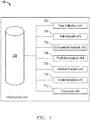
- Figure 14 depicts a schematic view of a pipeline analysis system 1400.
- the analysis system 1400 may be for analyzing conditions and/or damage to a pipeline and/or pipeline infrastructure 1402.
- the pipeline infrastructure 1402 is a pipeline 1404 for transporting gases or fluids therethrough.
- the pipeline analysis system 1400 may have the pipeline infrastructure 1402, one or more field workers 1408, one or more data collection tools 1410, one or more data input devices 1412, a communication network 1414 and a pipeline infrastructure unit 1416.
- the pipeline analysis system 1400 may have one or more analysis workers 1418 at a service company 1420.
- the service company 1420 may be hired to perform analysis, maintenance, remediation, and/or construction on the pipeline infrastructure 1402.
- the pipeline analysis system 1400 may communicate with a client company 1422.
- the service company 1420 and/or the client company 1422 may have any number of computers 1424 which may have the pipeline infrastructure unit 1416 therein.
- the field worker may have a computer 1424.
- the pipeline infrastructure 1402 may have the pipeline 1404 with one or more damaged portions 1426a-e (or greater).
- the pipeline infrastructure 1402 may have any suitable devices or equipment for supporting the transportation of gases or fluids in the pipeline 1404 including, but not limited to, pipe supports 1428, compressor stations (not shown), pumps (not shown), valves, and the like.
- the damaged portions 1426 of the pipeline 1404 may be due to corrosion of the pipeline 1404.
- the damaged portions 1426 may be caused by any suitable factors including, but not limited to, weather, pH of soil, cathodic corrosion, biological corrosion 1404 and the like.
- the damaged portion may be structural damage due to installation, impact, vandalism, and the like.
- the field worker 1408 may be any suitable worker (such as a technician or an engineer) that is sent to the pipeline infrastructure 1402 to collect data during a data collection phase of the project.
- the field worker 1408 may input the collected data directly into the one or more data input devices 1412 and/or the computer 1424 as the data is collected in the field.
- the one or more data collection tools 1410 may communicate directly with the one or more data input devices 1412 and/or the computer 1424 or the field worker 1408 may input the collected data manually.
- the one or more data input devices 1412 and/or the computer 1424 may send the data to the pipeline infrastructure unit(s) 1416 located about the pipeline analysis system 1400.
- the field worker 1408 may collect data for the pipeline 1404 as the field worker 1408 travels along the pipeline 1404. Further, the field worker 1408 may collect data from only a select section of the pipeline 1404 and then use the pipeline analysis system 1400 to predict the conditions along the pipeline 1404 and formulate a project plan, or implementation plan.
- the one or more data collection tools 1410 may be any suitable device(s) for measuring conditions about the pipeline infrastructure 1402.
- the field worker 1408 may use a caliper to measure the corrosion at the damaged portions 1426.
- the caliper may be any suitable caliper including but not limited to a digital caliper.
- the data collection tools 1410 may be any suitable tools for collecting data concerning the damage and contributing factors including, but not limited to, a laser scanner, acoustic tools, cameras, GPS devices, surveying equipment, soil testers (such as pH, resistivity or redox), structure potentials as referenced to a copper-copper-sulfate reference cell, coating condition, water pH the field workers experience, pressure monitors, flow meters, a pipeline pig, a handheld computer with one or more data input features, data collection tools described herein, and the like.
- a laser scanner acoustic tools, cameras, GPS devices, surveying equipment, soil testers (such as pH, resistivity or redox), structure potentials as referenced to a copper-copper-sulfate reference cell, coating condition, water pH the field workers experience, pressure monitors, flow meters, a pipeline pig, a handheld computer with one or more data input features, data collection tools described herein, and the like.
- the communication network 1414 allows for communication about the pipeline analysis system 1400 and may be any suitable network including those described herein.
- the field worker 1408 may collect data from all, or portions of, the pipeline infrastructure 1402 during a data gathering phase of the project. During the data gathering phase the field worker 1408 may use the data collection tools 1410 and/or observation at the pipeline infrastructure 1402. The data collection may take place during routine pipeline surveys including, but not limited to, annual surveys. Further, the data collection may take place due to the identification of a specific problem along the pipeline including, but not limited, to a leaking pipeline, a corroded portion of the pipeline and the like.
- the data collection may include identifying the damaged portions 1426a-e.
- the field worker 1408 may perform a more thorough investigation of the damage. For example, the field worker 1408 may determine both externally and internally the size of the corroded area, the depth of the corrosion in the pipe, the wall thickness erosion in the pipe, the soil type, soil resistivity, pipe-to-soil potentials, the material the pipeline is constructed with, the type thickness and condition of coating on the pipeline, coating damage, recoating data, defect size and/or location, the paint on the pipeline, paint damage, weld type and condition, magnetic particle analysis for crack identification, pH content, mapping of damaged areas, defect remaining strength analysis, corrosion product analysis, photos or digital imaging, dimensions of excavated areas, site sketches, depth of cover, global positioning, and the like. Further, a pig, or pipe pig, or digital pig may collect data regarding the condition of the pipeline as the pig travels through the pipeline.
- the collected data may be automatically and/or manually input into the one or more data input devices 1412 and/or the computer 1424.
- the one or more data input devices 1412 may be any suitable data input devices including, but not limited to, a tablet computer, a personal digital assistant, a smart phone, a laptop, a desktop, any suitable data input device described herein and the like.
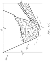
- Figure 15 depicts two damaged portions 1426a and 1426b in an example.
- the damaged portion 1426a may be a very small corroded portion of the pipeline.
- the field worker 1408 may collect data regarding this damaged portion 1426a and provide a location on the pipeline 1404 to the pipeline infrastructure unit 1416 by any suitable method described herein.
- the damaged portion 1426b may be a larger damaged area that requires more detailed analysis, or mapping of the corrosion.
- a corrosion grid 1500 may be drawn on the pipeline 1404.
- the data collection tools 1410 may map the specific conditions of the corrosion along the entire corrosion grid 1500.
- the corrosion grid 1500 may be drawn on the pipeline 1404 by the field worker 1408, or may be put on the pipeline 1404 via one of the data collection tools 1410.
- the collected data and/or the data elements for each of the pipelines 1404 surveyed may be sent to the pipeline infrastructure unit(s) 1416 via the data collection tools 1410, the data input devices 1412, the computer 1424 used by the field worker 1408, and/or entered by the worker 1408 at the service company 1420.
- the worker 1418 at the service company 1420 may input the data into the pipeline infrastructure unit 1416 from data collected in a data collection phase.
- FIG. 16 depicts a block diagram of the pipeline infrastructure unit 1416 according to an embodiment.
- the pipeline infrastructure unit 1416 may include a storage device 1600, a data collection unit 1602, a risk analysis unit 1604, a predictive analysis unit 1606, a mitigation unit 1608, an implementation unit 1610, and/or a transceiver unit 1612.
- the storage device 1600 may be any suitable storage device for storing data.
- the transceiver unit 1612 may be any suitable device configured to send and/or receive data to the pipeline infrastructure unit 1416.
- the pipeline infrastructure unit 1416 may be totally or partially located in the one or more data collection tools 1410, the one or more data input devices 1412, the computers 1424, at the service company 1420, client company 1422 and/or with the field worker 1408, and/or the network 1414.
- the risk analysis unit 1604 may have a transmission corrosion analysis tool (TCATTM), pipeline version.
- TCATTM allows the workers to acquire, store and manage pipeline related data and timely performance of risk ranking calculations. This may allow for quick identification of pipeline sections/areas with damage and/or the highest risk of damage and timely direction of remediation crews to those high risk pipelines 1404 and/or damaged portion 1426.
- Figure 18A through Figure 18H depict various screen shots of a visual display (with notations added) of the TCATTM ( Figure 18A representing an example main screenshot allowing user access to secondary screens including bell hole data, anomaly data, anomaly representation, and photos/images; and Figures 18B-18H representing various example layers optionally accessible via the main screen including Fig.
- Fig. 18B representing a bell hole data access screen, having drop down selections used to improve data consistency and allowing bell hole data entry
- Fig. 18C representing a pipeline anomaly data access screen
- Fig. 18D representing a coating anomaly data access screen
- Fig. 18E representing an external corrosion cell data access screen
- Fig. 18F representing an external corrosion grid data access screen
- Fig. 18G representing a pipeline anomaly representation visual and/or data access screen
- Fig. 18H representing a standard set of photos or digital image data access screen wherein a user can zoom into a specific photo by selecting it in the user interface system).
- the TCATTM may use an algorithm developed from expertise in corrosion, coating, bell hole, anomaly, etc. science and deployable via measurements.
- This algorithm integrates numerous data elements, by way of example only, around sixteen electrochemical, chemical, visual and/or physical measurements for the pipeline infrastructure 1402, such as the pipeline 1404, the pipe supports 1428, and/or the like.
- the algorithm may determine the relative likelihood of corrosion or damage of that pipeline infrastructure 1402.
- direct information or information used to infer conditions may be integrated, for example, the subsurface direct examination condition data of the interior and/or exterior of the pipeline 1404 may be inputted with direct observations. This allows the TCATTM model and the assessment team performance to improve in real time as data is collected for a specific assessment project, or implementation project.
- the TCATTM model and/or the risk analysis unit 1604 may characterize bell hole data, anomaly data, anomaly representation, visual images all in various forms including soil characteristics, electrochemical factors, electrical interferences, design, cathodic protection, topography, imaging and the like for the pipeline infrastructure 1402.
- the data collection unit 1602 may collect all of the data including, but not limited to, input by the field worker 1408 into the one or more data collection tools 1410 and/or the computer 1424. The data collection unit 1602 may then identify important data elements from the collected data. The data collection unit 1602 may then organize, store, categorize, and manipulate the collected data per the needs of the project. The data collection unit 1602 may further keep historical data regarding any of the collected data, data elements, and/or pipeline infrastructure 1402 as the data is collected.
- the collected data may further be categorized to determine external corrosion factors for each pipeline 1404 and/or damaged portion(s) 1426a-e of the pipeline.
- the external corrosion factors may include, but are not limited to, the size of the corrosion at each damaged portion 1426, the depth of the corrosion, the soil conditions, the atmospheric conditions, any conditions described herein, and the like.
- the risk analysis unit 1604 may receive information from the data collection unit 1602 to determine risk, or risk factors, in the pipeline infrastructure 1402.
- the risk analysis unit may have a tool to determine the likelihood that the pipeline 1404 will leak or burst.
- the risk analysis unit 1604 may determine the extent of actual corrosion and the rate of corrosion since installation of the pipeline 1404. Using the observed and operating conditions of the pipeline, the risk analysis unit 1604 may determine the likelihood of a leak to the pipeline 1404.
- the predictive analysis unit 1606 may take the data from the data collection unit 1602, the risk analysis unit 1604 in order to predict the future corrosion of the pipeline 1404.
- the predictive analysis unit 1606 may generate a corrosion report that details the extent of the actual corrosion, the likelihood of a current pipeline leak, the probability and extent of future corrosion and/or damage, and the likelihood of a pipeline leak in the future.
- the mitigation unit 1608 may take the data generated by the predictive analysis unit 1606 and determine which portions of the pipeline infrastructure 1402 need work.
- the mitigation unit 1608 may determine the type and scale of work to be performed on the pipeline infrastructure 1402.
- the mitigation unit 1608 may generate a mitigation report detailing the exact location and type of work to be done on the pipeline 1404.
- the mitigation unit 1608 may recommend any suitable type of work for the pipeline infrastructure 1402 including, but not limited to, painting, applying a protective coating, installing a sleeve over any damaged portion 1426, replacing a portion of the pipeline 1404, any combination thereof, and the like.
- the implementation unit 1610 may generate an implementation plan.
- the implementation plan may determine how soon the work on the pipeline infrastructure 1402 is to be performed and the extent of the work to be performed. For example, if it is determined that there is a probability of a leak in the pipeline 1404, the implementation plan may enact a plan to have that portion of the pipeline infrastructure 1402 fixed immediately. Further, the implementation unit 1610 may determine a time table for future work and maintenance of the pipeline infrastructure 1402 based on the mitigation plan.
- All of the functions of the pipeline infrastructure unit 1416 and/or the infrastructure unit 116 may be performed in real time while the field worker is inputting the collected data into the pipeline infrastructure unit 1416 and/or the infrastructure unit 116.
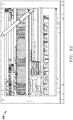
- Figures 17A-17H depict an example of a report used in conjunction with the pipeline analysis system 1400 according to an embodiment.
- the infrastructure unit 116 and/or the pipeline infrastructure unit 1416 may take the form of an entirely hardware embodiment, entirely software embodiment (including firmware, resident software, micro-code, etc.) or an embodiment combining software and hardware aspects.
- Embodiments may take the form of a computer program embodied in any medium having computer usable program code embodied in the medium.
- the embodiments may be provided as a computer program product, or software, that may include a machine-readable medium having stored thereon instructions, which may be used to program a computer system (or other electronic device(s)) to perform a process.
- a machine readable medium includes any mechanism for storing or transmitting information in a form (such as, software, processing application) readable by a machine (such as a computer).
- the machine-readable medium may include, but is not limited to, magnetic storage medium (e.g., floppy diskette); optical storage medium (e.g., CD-ROM); magneto-optical storage medium; read only memory (ROM); random access memory (RAM); erasable programmable memory (e.g., EPROM and EEPROM); flash memory; or other types of medium suitable for storing electronic instructions.
- Embodiments may further be embodied in an electrical, optical, acoustical or other form of propagated signal (e.g., carrier waves, infrared signals, digital signals, etc.), or wireline, wireless, or other communications medium. Further, it should be appreciated that the embodiments may take the form of hand calculations, and/or operator comparisons. To this end, the workers, operator and/or engineer(s) may receive, manipulate, catalog and store the data from the system 100/1400 in order to perform tasks depicted in the infrastructure unit 116 and/or the pipeline infrastructure unit 1416.
Landscapes
- Engineering & Computer Science (AREA)
- General Engineering & Computer Science (AREA)
- Mechanical Engineering (AREA)
- Life Sciences & Earth Sciences (AREA)
- Physics & Mathematics (AREA)
- General Health & Medical Sciences (AREA)
- Immunology (AREA)
- Ecology (AREA)
- Environmental & Geological Engineering (AREA)
- Environmental Sciences (AREA)
- Health & Medical Sciences (AREA)
- Chemical & Material Sciences (AREA)
- Analytical Chemistry (AREA)
- Biochemistry (AREA)
- Pathology (AREA)
- General Physics & Mathematics (AREA)
- Biodiversity & Conservation Biology (AREA)
- Acoustics & Sound (AREA)
- Testing Resistance To Weather, Investigating Materials By Mechanical Methods (AREA)
- Management, Administration, Business Operations System, And Electronic Commerce (AREA)
- Analysing Materials By The Use Of Radiation (AREA)
- Solid-Sorbent Or Filter-Aiding Compositions (AREA)
- Carbon And Carbon Compounds (AREA)
- Investigating Or Analyzing Materials By The Use Of Electric Means (AREA)
- Supply And Distribution Of Alternating Current (AREA)
- Remote Monitoring And Control Of Power-Distribution Networks (AREA)
- Testing Of Devices, Machine Parts, Or Other Structures Thereof (AREA)
- Testing And Monitoring For Control Systems (AREA)
Claims (8)
- Rohrleitungsanalysesystem (1400), umfassend:eine entfernte Rohrleitungsinfrastruktur (1402), umfassend:
eine korrodierbare Rohrleitung (1404), die konfiguriert ist, um Fluide zu transportieren;eine Vielzahl von Datenerfassungswerkzeugen (1410), die konfiguriert sind, um Daten von der entfernten Rohrleitungsinfrastruktur zu erfassen, wobei die Vielzahl von Datenerfassungswerkzeugen, die in dem Analysesystem enthalten sind, eine Kamera, eine GPS-Vorrichtung, eine Vermessungsvorrichtung, ein Bodentester, ein Werkzeug zum Messen eines elektrochemischen Potenzials einer Struktur, ein Werkzeug zum Messen der Korrosion von Metall, eine Grubentiefenmessvorrichtung, eine Beschichtungsmessvorrichtung, ein Bodensäure-Messwerkzeug, ein Bodenoxidations-Reduktionsmesswerkzeug, ein Bodenwiderstandsmesswerkzeug, ein Messschieber, ein Messschieber, ein Wasser-pH-Prüfer und ein Mittel zum Umwandeln einer visuellen Inspektion sind;wobei das Analysesystem konfiguriert ist, um Daten aus der zerstörungsfreien Prüfung einer Komponente der Infrastruktur zu sammeln; eineRohrleitungsinfrastruktureinheit (1416), die konfiguriert ist, um Daten von den Datenerfassungswerkzeugen und Ergebnisse der zerstörungsfreien Prüfung zu empfangen;wobei die Rohrleitungsinfrastruktureinheit umfasst:eine Datenerfassungseinheit (1602), die konfiguriert ist, um Daten bezüglich der entfernten Rohrleitungsinfrastruktur von den Datenerfassungswerkzeugen und den Ergebnissen der zerstörungsfreien Prüfung zu empfangen;eine Risikoanalyseeinheit, die konfiguriert ist, um einen Korrosionszustand der korrodierbaren Rohrleitung basierend auf den empfangenen Daten zu bewerten;eine prädiktive Analyseeinheit, die auf die Datenerfassungseinheit und die Risikoanalyseeinheit reagiert, die konfiguriert ist, um einen Korrosionsbericht zu erstellen, der die tatsächliche Korrosion, die Wahrscheinlichkeit eines aktuellen Rohrleitungslecks und die Wahrscheinlichkeit einer zukünftigen Korrosion aufführt;eine Minderungseinheit, die konfiguriert ist, um eine Art von Minderungsarbeiten zu bestimmen, die an der korrodierbaren Rohrleitung durchzuführen sind; und eine Implementierungseinheit (1610), die konfiguriert ist, um das relative Risiko für die entfernte Rohrleitungsinfrastruktur zu bewerten und einen Implementierungsplan für die Wiederherstellung der entfernten Rohrleitungsinfrastruktur zu erstellen. - Rohrleitungsanalysesystem nach Anspruch 1, ferner umfassend mindestens eine Dateneingabevorrichtung (1412), die konfiguriert ist, um Daten von den Datenerfassungswerkzeugen zu erfassen.
- Rohrleitungsanalysesystem nach Anspruch 1, wobei die Vielzahl von Datenerfassungswerkzeugen (1410) zusätzlich einen Molch umfasst.
- Rohrleitungsanalysesystem nach Anspruch 1, wobei die Vielzahl von Datenerfassungswerkzeugen (1410) ferner einen Scanner, ein akustisches Werkzeug, einen Druckwächter und einen Durchflussmesser umfasst.
- Rohrleitungsanalysesystem nach Anspruch 1, wobei die Vielzahl von Datenerfassungswerkzeugen (1410) zusätzlich ein Werkzeug umfasst, das aus der Gruppe von Werkzeugen ausgewählt ist, die aus einem akustischen Werkzeug, einem Druckwächter und einem Durchflussmesser besteht.
- Infrastruktur-Sanierungsverfahren unter Verwendung des Rohrleitungsanalysesystems nach einem der Ansprüche 1-5, wobei das Verfahren den Schritt des Ausführens des Implementierungsplans zur Sanierung der entfernten Rohrleitungsinfrastruktur umfasst.
- Infrastruktur-Sanierungsverfahren nach Anspruch 6, umfassend den zusätzlichen Schritt des elektronischen Speicherns aller empfangenen Daten, die von der entfernten Rohrleitungsinfrastruktur gesammelt wurden, um auf die empfangenen Daten zuzugreifen und sie zu einem zukünftigen Zeitpunkt zu manipulieren.
- Infrastruktur-Sanierungsverfahren nach Anspruch 6, umfassend den zusätzlichen Schritt des Eingebens der empfangenen Daten, die der entfernten Rohrleitungsinfrastruktur zugeordnet sind, in einen Computer, der sich an der entfernten Rohrleitungsinfrastruktur befindet.
Applications Claiming Priority (3)
| Application Number | Priority Date | Filing Date | Title |
|---|---|---|---|
| US201161482538P | 2011-05-04 | 2011-05-04 | |
| US201261598192P | 2012-02-13 | 2012-02-13 | |
| PCT/US2012/036611 WO2012151535A1 (en) | 2011-05-04 | 2012-05-04 | Energy infrastructure risk analysis and remediation |
Publications (3)
| Publication Number | Publication Date |
|---|---|
| EP2705409A1 EP2705409A1 (de) | 2014-03-12 |
| EP2705409A4 EP2705409A4 (de) | 2014-09-24 |
| EP2705409B1 true EP2705409B1 (de) | 2019-06-19 |
Family
ID=47089431
Family Applications (1)
| Application Number | Title | Priority Date | Filing Date |
|---|---|---|---|
| EP12779531.8A Active EP2705409B1 (de) | 2011-05-04 | 2012-05-04 | Pipeline-analysesystem und sanierungsmethode |
Country Status (11)
| Country | Link |
|---|---|
| US (3) | US9683924B2 (de) |
| EP (1) | EP2705409B1 (de) |
| AU (3) | AU2012250586B2 (de) |
| BR (1) | BR112013028437A2 (de) |
| CA (3) | CA3202340A1 (de) |
| CL (1) | CL2013003155A1 (de) |
| CO (1) | CO6811822A2 (de) |
| ES (1) | ES2763642T3 (de) |
| GT (1) | GT201300264A (de) |
| WO (1) | WO2012151535A1 (de) |
| ZA (1) | ZA201307915B (de) |
Families Citing this family (27)
| Publication number | Priority date | Publication date | Assignee | Title |
|---|---|---|---|---|
| ES2763642T3 (es) | 2011-05-04 | 2020-05-29 | Quanta Ass Lp | Sistema de análisis de conducciones y método de reparación |
| US9183527B1 (en) * | 2011-10-17 | 2015-11-10 | Redzone Robotics, Inc. | Analyzing infrastructure data |
| EP3201562A4 (de) | 2014-09-29 | 2018-04-11 | Sikorsky Aircraft Corporation | Vorrichtung zur erkennung von korrosion an einem gegenstand |
| US20160155097A1 (en) * | 2014-12-02 | 2016-06-02 | Ebay Inc. | Reports of repairable objects and events |
| CN104537208B (zh) * | 2014-12-08 | 2017-11-07 | 中国石油天然气股份有限公司 | 一种输油站场埋地工艺管网腐蚀泄漏风险评价方法及装置 |
| JP6363971B2 (ja) * | 2015-06-03 | 2018-07-25 | 日本電信電話株式会社 | 推定方法および推定装置 |
| US10330587B2 (en) | 2015-08-31 | 2019-06-25 | Exxonmobil Upstream Research Company | Smart electrochemical sensor for pipeline corrosion measurement |
| US10060578B2 (en) * | 2016-05-16 | 2018-08-28 | International Business Machines Corporation | Automated gas detection and reporting system |
| US10163242B2 (en) * | 2017-01-31 | 2018-12-25 | Gordon Todd Jagerson, Jr. | Energy grid data platform |
| US10895556B2 (en) * | 2017-03-21 | 2021-01-19 | Baker Hughes Oilfield Operations Llc | Predictive integrity analysis |
| US11543080B2 (en) * | 2017-05-23 | 2023-01-03 | Lux Modus Ltd. | Automated pipeline construction modelling |
| CN107145685B (zh) * | 2017-06-06 | 2018-03-16 | 北京市燃气集团有限责任公司 | 基于北斗的管道动态直流干扰监测系统及风险评估方法 |
| US10724940B2 (en) | 2017-06-28 | 2020-07-28 | General Electric Company | System for monitoring and controlling equipment life due to corrosion degradation |
| US10539498B2 (en) * | 2017-08-18 | 2020-01-21 | Saudi Arabian Oil Company | High pressure / high temperature dynamic multiphase corrosion-erosion simulator |
| US10871444B2 (en) * | 2018-08-30 | 2020-12-22 | Saudi Arabian Oil Company | Inspection and failure detection of corrosion under fireproofing insulation using a hybrid sensory system |
| WO2020231442A1 (en) * | 2019-05-16 | 2020-11-19 | Landmark Graphics Corporation | Corrosion prediction for integrity assessment of metal tubular structures |
| CN110539062B (zh) * | 2019-09-29 | 2023-08-22 | 华南理工大学 | 一种深海管道等离子增材制造原位修复设备与方法 |
| CA3095393A1 (en) | 2019-10-11 | 2021-04-11 | Matergenics, Inc. | Atmospheric corrosivity mapping method and apparatus |
| CN113762651B (zh) * | 2020-05-28 | 2024-03-29 | 中国石油天然气股份有限公司 | 井口装置的剩余强度评估方法 |
| GB202009384D0 (en) * | 2020-06-19 | 2020-08-05 | Pulse-Uk Ltd | System and method for identifying a pipe |
| US20220065406A1 (en) * | 2020-08-26 | 2022-03-03 | Saudi Arabian Oil Company | Assessment of external coating degradation severity for buried pipelines |
| CN113189146B (zh) * | 2021-04-16 | 2024-05-28 | 国网甘肃省电力公司经济技术研究院 | 一种导电混凝土接地网监测大地裂隙滑坡的装置及方法 |
| US12105011B2 (en) * | 2021-07-12 | 2024-10-01 | Titan Hre Llc | Apparatus and system for automated assessment of cathodic protection system for pipelines |
| CN116228187A (zh) * | 2022-12-16 | 2023-06-06 | 东南大学 | 一种多级腐蚀缺陷管道系统的维修策略优化方法 |
| CN116870509B (zh) * | 2023-07-31 | 2025-07-25 | 福建汉芯科技有限公司 | 一种用于半导体级和电子级的氢氟酸高效精馏装置 |
| CN118229078A (zh) * | 2024-03-26 | 2024-06-21 | 广东电网有限责任公司中山供电局 | 基于用户数据的电力执行效果的分析方法及装置 |
| CN118442548B (zh) * | 2024-07-08 | 2024-09-13 | 成都秦川物联网科技股份有限公司 | 基于智慧燃气物联网的管线运行状态安全监测方法和系统 |
Family Cites Families (16)
| Publication number | Priority date | Publication date | Assignee | Title |
|---|---|---|---|---|
| US6992482B2 (en) * | 2000-11-08 | 2006-01-31 | Jentek Sensors, Inc. | Magnetic field sensor having a switchable drive current spatial distribution |
| US6822432B2 (en) * | 2001-06-22 | 2004-11-23 | Network Technologies Group, Llc | Methods and systems for automated pipeline testing |
| US7359931B2 (en) * | 2003-08-15 | 2008-04-15 | Saudi Arabian Oil Company | System to facilitate pipeline management, software, and related methods |
| WO2005026919A2 (en) * | 2003-09-11 | 2005-03-24 | Bradford Addison Clough | Acquisition and analysis of time location-specific image data |
| US8234876B2 (en) * | 2003-10-15 | 2012-08-07 | Ice Energy, Inc. | Utility managed virtual power plant utilizing aggregated thermal energy storage |
| WO2005059294A2 (en) * | 2003-12-11 | 2005-06-30 | Marathon Ashland Petroleum Llc | Pipeline integrity management process |
| US6970808B2 (en) * | 2004-04-29 | 2005-11-29 | Kingsley E. Abhulimen | Realtime computer assisted leak detection/location reporting and inventory loss monitoring system of pipeline network systems |
| US20060068754A1 (en) * | 2004-09-30 | 2006-03-30 | Helena Goldfarb | System and method for securing a large infrastructure |
| US7767093B2 (en) | 2005-01-21 | 2010-08-03 | Bernard Frank | Method for end-to-end control of water quality |
| US7497957B2 (en) * | 2005-01-21 | 2009-03-03 | Bernard Frank | System, method and apparatus for end-to-end control of water quality |
| NL1033148C2 (nl) * | 2006-12-29 | 2008-07-01 | Univ Delft Tech | Elektrische meetinrichting, werkwijze en computer programma product. |
| CA2728409A1 (en) * | 2008-06-18 | 2009-12-23 | Biocorrosion Solutions Inc. | Method and device for eliminating microbes within industrial pipelines |
| US8112304B2 (en) * | 2008-08-15 | 2012-02-07 | Raytheon Company | Method of risk management across a mission support network |
| US20100088139A1 (en) * | 2008-10-07 | 2010-04-08 | Rahi M Ahsan | Project management system adapted for planning and managing projects |
| US8554386B2 (en) * | 2010-06-02 | 2013-10-08 | Serge Rutman | System and method for self-powered communications networks |
| ES2763642T3 (es) | 2011-05-04 | 2020-05-29 | Quanta Ass Lp | Sistema de análisis de conducciones y método de reparación |
-
2012
- 2012-05-04 ES ES12779531T patent/ES2763642T3/es active Active
- 2012-05-04 CA CA3202340A patent/CA3202340A1/en active Pending
- 2012-05-04 BR BR112013028437A patent/BR112013028437A2/pt not_active IP Right Cessation
- 2012-05-04 CA CA3108736A patent/CA3108736C/en active Active
- 2012-05-04 US US13/464,729 patent/US9683924B2/en active Active
- 2012-05-04 EP EP12779531.8A patent/EP2705409B1/de active Active
- 2012-05-04 AU AU2012250586A patent/AU2012250586B2/en active Active
- 2012-05-04 CA CA2833558A patent/CA2833558C/en active Active
- 2012-05-04 WO PCT/US2012/036611 patent/WO2012151535A1/en not_active Ceased
-
2013
- 2013-10-23 ZA ZA2013/07915A patent/ZA201307915B/en unknown
- 2013-10-28 GT GT201300264A patent/GT201300264A/es unknown
- 2013-10-30 CL CL2013003155A patent/CL2013003155A1/es unknown
- 2013-12-04 CO CO13284403A patent/CO6811822A2/es not_active Application Discontinuation
-
2017
- 2017-04-27 AU AU2017202778A patent/AU2017202778B2/en active Active
- 2017-06-19 US US15/627,070 patent/US10928299B2/en active Active
-
2020
- 2020-09-18 AU AU2020233781A patent/AU2020233781B2/en active Active
-
2021
- 2021-02-22 US US17/181,502 patent/US11635366B2/en active Active
Non-Patent Citations (1)
| Title |
|---|
| None * |
Also Published As
| Publication number | Publication date |
|---|---|
| AU2017202778B2 (en) | 2019-03-21 |
| EP2705409A4 (de) | 2014-09-24 |
| AU2020233781B2 (en) | 2022-01-06 |
| ZA201307915B (en) | 2015-01-28 |
| US10928299B2 (en) | 2021-02-23 |
| CA2833558C (en) | 2021-03-16 |
| ES2763642T3 (es) | 2020-05-29 |
| CA3108736A1 (en) | 2012-11-08 |
| US20120279599A1 (en) | 2012-11-08 |
| CA2833558A1 (en) | 2012-11-08 |
| CA3202340A1 (en) | 2012-11-08 |
| AU2020233781A1 (en) | 2020-10-15 |
| CO6811822A2 (es) | 2013-12-16 |
| CL2013003155A1 (es) | 2014-11-07 |
| US9683924B2 (en) | 2017-06-20 |
| US20210172858A1 (en) | 2021-06-10 |
| AU2012250586A1 (en) | 2013-11-07 |
| EP2705409A1 (de) | 2014-03-12 |
| US20170307510A1 (en) | 2017-10-26 |
| AU2012250586B2 (en) | 2017-02-02 |
| GT201300264A (es) | 2015-01-22 |
| WO2012151535A1 (en) | 2012-11-08 |
| CA3108736C (en) | 2023-08-01 |
| US11635366B2 (en) | 2023-04-25 |
| BR112013028437A2 (pt) | 2017-01-24 |
| AU2017202778A1 (en) | 2017-05-18 |
Similar Documents
| Publication | Publication Date | Title |
|---|---|---|
| US11635366B2 (en) | Infrastructure corrosion analysis | |
| Tan | Localized corrosion in complex environments | |
| Szeliga et al. | Evaluating ductile iron pipe corrosion | |
| Van Os et al. | An external corrosion direct assessment module for a pipeline integrity management system | |
| Rezaie et al. | Corrosion Risk Assessment at Anchor Shafts of Telecommunication Towers | |
| Jawed | Transmission Tower Corrosion Management | |
| Daily et al. | Interpretation of CIS Potential Profile with Respect to ECDA Methodology | |
| Lewandowski | Gas pipelines corrosion data analysis and related topics | |
| Fryett et al. | Electric Transmission Tower Corrosion Analysis Tool | |
| Clothier et al. | Practical Application of Force Main Condition Assessment Methodologies for Long Term Asset Management Needs | |
| Hunt et al. | Establishing an Evaluation Matrix for Condition Assessment of Water Mains | |
| Kusumawardhani | Reliability Analysis on Non-Destructive Testing of Topside Flow-Line Pipe System on Aging Platform: Plant, Human, and Technology | |
| Girardot et al. | Hanford Single-Shell Tank and Double-Shell Tank Integrity Programs | |
| Pillai | Direct Assessment Data Categorization, Integration And Risk Indexation-A Novel Approach | |
| Anes-Arteche | Data analysis for improved risk assessment in underground pipelines | |
| Heffron et al. | New ASCE Standard Practice Manual for Underwater Investigations | |
| Williams et al. | Developing a Standardized Process for Cathodic Protection Current Measurement on In-Service Pipelines–Process and Procedures for a New Technology | |
| Mullins | Remote Monitoring of Bridges | |
| Chaves et al. | Reliability based evaluation of commonly applied corrosion mitigation techniques | |
| Tan et al. | Visualizing dynamic corrosion and coating disbondment processes on simulated pipeline conditions | |
| Gossard et al. | CP Simulation of Offshore Platforms for Inspection Optimization | |
| Pipes | CORRPRO COMPANIES, INC. | |
| Pikas et al. | Are You Trained, Certified and Qualified to Assess Corrosion and Related Defects? | |
| Silvianita | Prioritizing the Maintenance of Pipeline Based on Risk Analysis | |
| Murray et al. | Pipeline Integrity and Security |
Legal Events
| Date | Code | Title | Description |
|---|---|---|---|
| PUAI | Public reference made under article 153(3) epc to a published international application that has entered the european phase |
Free format text: ORIGINAL CODE: 0009012 |
|
| 17P | Request for examination filed |
Effective date: 20131018 |
|
| AK | Designated contracting states |
Kind code of ref document: A1 Designated state(s): AL AT BE BG CH CY CZ DE DK EE ES FI FR GB GR HR HU IE IS IT LI LT LU LV MC MK MT NL NO PL PT RO RS SE SI SK SM TR |
|
| DAX | Request for extension of the european patent (deleted) | ||
| A4 | Supplementary search report drawn up and despatched |
Effective date: 20140822 |
|
| RIC1 | Information provided on ipc code assigned before grant |
Ipc: G01M 3/00 20060101ALI20140818BHEP Ipc: G05B 9/02 20060101AFI20140818BHEP Ipc: F17D 5/00 20060101ALI20140818BHEP Ipc: F16L 55/26 20060101ALI20140818BHEP |
|
| STAA | Information on the status of an ep patent application or granted ep patent |
Free format text: STATUS: EXAMINATION IS IN PROGRESS |
|
| 17Q | First examination report despatched |
Effective date: 20170918 |
|
| REG | Reference to a national code |
Ref country code: DE Ref legal event code: R079 Ref document number: 602012061199 Country of ref document: DE Free format text: PREVIOUS MAIN CLASS: G05B0009020000 Ipc: G01N0017000000 |
|
| RIC1 | Information provided on ipc code assigned before grant |
Ipc: F17D 3/01 20060101ALI20181011BHEP Ipc: F17D 5/06 20060101ALI20181011BHEP Ipc: G01N 17/00 20060101AFI20181011BHEP |
|
| GRAP | Despatch of communication of intention to grant a patent |
Free format text: ORIGINAL CODE: EPIDOSNIGR1 |
|
| STAA | Information on the status of an ep patent application or granted ep patent |
Free format text: STATUS: GRANT OF PATENT IS INTENDED |
|
| INTG | Intention to grant announced |
Effective date: 20190103 |
|
| GRAS | Grant fee paid |
Free format text: ORIGINAL CODE: EPIDOSNIGR3 |
|
| GRAA | (expected) grant |
Free format text: ORIGINAL CODE: 0009210 |
|
| STAA | Information on the status of an ep patent application or granted ep patent |
Free format text: STATUS: THE PATENT HAS BEEN GRANTED |
|
| AK | Designated contracting states |
Kind code of ref document: B1 Designated state(s): AL AT BE BG CH CY CZ DE DK EE ES FI FR GB GR HR HU IE IS IT LI LT LU LV MC MK MT NL NO PL PT RO RS SE SI SK SM TR |
|
| REG | Reference to a national code |
Ref country code: GB Ref legal event code: FG4D |
|
| REG | Reference to a national code |
Ref country code: CH Ref legal event code: EP |
|
| REG | Reference to a national code |
Ref country code: IE Ref legal event code: FG4D |
|
| REG | Reference to a national code |
Ref country code: AT Ref legal event code: REF Ref document number: 1146152 Country of ref document: AT Kind code of ref document: T Effective date: 20190715 |
|
| REG | Reference to a national code |
Ref country code: DE Ref legal event code: R096 Ref document number: 602012061199 Country of ref document: DE |
|
| REG | Reference to a national code |
Ref country code: NL Ref legal event code: MP Effective date: 20190619 |
|
| PG25 | Lapsed in a contracting state [announced via postgrant information from national office to epo] |
Ref country code: FI Free format text: LAPSE BECAUSE OF FAILURE TO SUBMIT A TRANSLATION OF THE DESCRIPTION OR TO PAY THE FEE WITHIN THE PRESCRIBED TIME-LIMIT Effective date: 20190619 Ref country code: HR Free format text: LAPSE BECAUSE OF FAILURE TO SUBMIT A TRANSLATION OF THE DESCRIPTION OR TO PAY THE FEE WITHIN THE PRESCRIBED TIME-LIMIT Effective date: 20190619 Ref country code: AL Free format text: LAPSE BECAUSE OF FAILURE TO SUBMIT A TRANSLATION OF THE DESCRIPTION OR TO PAY THE FEE WITHIN THE PRESCRIBED TIME-LIMIT Effective date: 20190619 Ref country code: SE Free format text: LAPSE BECAUSE OF FAILURE TO SUBMIT A TRANSLATION OF THE DESCRIPTION OR TO PAY THE FEE WITHIN THE PRESCRIBED TIME-LIMIT Effective date: 20190619 Ref country code: NO Free format text: LAPSE BECAUSE OF FAILURE TO SUBMIT A TRANSLATION OF THE DESCRIPTION OR TO PAY THE FEE WITHIN THE PRESCRIBED TIME-LIMIT Effective date: 20190919 Ref country code: LT Free format text: LAPSE BECAUSE OF FAILURE TO SUBMIT A TRANSLATION OF THE DESCRIPTION OR TO PAY THE FEE WITHIN THE PRESCRIBED TIME-LIMIT Effective date: 20190619 |
|
| REG | Reference to a national code |
Ref country code: LT Ref legal event code: MG4D |
|
| PG25 | Lapsed in a contracting state [announced via postgrant information from national office to epo] |
Ref country code: GR Free format text: LAPSE BECAUSE OF FAILURE TO SUBMIT A TRANSLATION OF THE DESCRIPTION OR TO PAY THE FEE WITHIN THE PRESCRIBED TIME-LIMIT Effective date: 20190920 Ref country code: RS Free format text: LAPSE BECAUSE OF FAILURE TO SUBMIT A TRANSLATION OF THE DESCRIPTION OR TO PAY THE FEE WITHIN THE PRESCRIBED TIME-LIMIT Effective date: 20190619 Ref country code: BG Free format text: LAPSE BECAUSE OF FAILURE TO SUBMIT A TRANSLATION OF THE DESCRIPTION OR TO PAY THE FEE WITHIN THE PRESCRIBED TIME-LIMIT Effective date: 20190919 Ref country code: LV Free format text: LAPSE BECAUSE OF FAILURE TO SUBMIT A TRANSLATION OF THE DESCRIPTION OR TO PAY THE FEE WITHIN THE PRESCRIBED TIME-LIMIT Effective date: 20190619 |
|
| REG | Reference to a national code |
Ref country code: AT Ref legal event code: MK05 Ref document number: 1146152 Country of ref document: AT Kind code of ref document: T Effective date: 20190619 |
|
| PG25 | Lapsed in a contracting state [announced via postgrant information from national office to epo] |
Ref country code: RO Free format text: LAPSE BECAUSE OF FAILURE TO SUBMIT A TRANSLATION OF THE DESCRIPTION OR TO PAY THE FEE WITHIN THE PRESCRIBED TIME-LIMIT Effective date: 20190619 Ref country code: SK Free format text: LAPSE BECAUSE OF FAILURE TO SUBMIT A TRANSLATION OF THE DESCRIPTION OR TO PAY THE FEE WITHIN THE PRESCRIBED TIME-LIMIT Effective date: 20190619 Ref country code: PT Free format text: LAPSE BECAUSE OF FAILURE TO SUBMIT A TRANSLATION OF THE DESCRIPTION OR TO PAY THE FEE WITHIN THE PRESCRIBED TIME-LIMIT Effective date: 20191021 Ref country code: NL Free format text: LAPSE BECAUSE OF FAILURE TO SUBMIT A TRANSLATION OF THE DESCRIPTION OR TO PAY THE FEE WITHIN THE PRESCRIBED TIME-LIMIT Effective date: 20190619 Ref country code: EE Free format text: LAPSE BECAUSE OF FAILURE TO SUBMIT A TRANSLATION OF THE DESCRIPTION OR TO PAY THE FEE WITHIN THE PRESCRIBED TIME-LIMIT Effective date: 20190619 Ref country code: AT Free format text: LAPSE BECAUSE OF FAILURE TO SUBMIT A TRANSLATION OF THE DESCRIPTION OR TO PAY THE FEE WITHIN THE PRESCRIBED TIME-LIMIT Effective date: 20190619 Ref country code: CZ Free format text: LAPSE BECAUSE OF FAILURE TO SUBMIT A TRANSLATION OF THE DESCRIPTION OR TO PAY THE FEE WITHIN THE PRESCRIBED TIME-LIMIT Effective date: 20190619 |
|
| PG25 | Lapsed in a contracting state [announced via postgrant information from national office to epo] |
Ref country code: IT Free format text: LAPSE BECAUSE OF FAILURE TO SUBMIT A TRANSLATION OF THE DESCRIPTION OR TO PAY THE FEE WITHIN THE PRESCRIBED TIME-LIMIT Effective date: 20190619 Ref country code: IS Free format text: LAPSE BECAUSE OF FAILURE TO SUBMIT A TRANSLATION OF THE DESCRIPTION OR TO PAY THE FEE WITHIN THE PRESCRIBED TIME-LIMIT Effective date: 20191019 Ref country code: SM Free format text: LAPSE BECAUSE OF FAILURE TO SUBMIT A TRANSLATION OF THE DESCRIPTION OR TO PAY THE FEE WITHIN THE PRESCRIBED TIME-LIMIT Effective date: 20190619 |
|
| PG25 | Lapsed in a contracting state [announced via postgrant information from national office to epo] |
Ref country code: TR Free format text: LAPSE BECAUSE OF FAILURE TO SUBMIT A TRANSLATION OF THE DESCRIPTION OR TO PAY THE FEE WITHIN THE PRESCRIBED TIME-LIMIT Effective date: 20190619 |
|
| PG25 | Lapsed in a contracting state [announced via postgrant information from national office to epo] |
Ref country code: PL Free format text: LAPSE BECAUSE OF FAILURE TO SUBMIT A TRANSLATION OF THE DESCRIPTION OR TO PAY THE FEE WITHIN THE PRESCRIBED TIME-LIMIT Effective date: 20190619 Ref country code: DK Free format text: LAPSE BECAUSE OF FAILURE TO SUBMIT A TRANSLATION OF THE DESCRIPTION OR TO PAY THE FEE WITHIN THE PRESCRIBED TIME-LIMIT Effective date: 20190619 |
|
| PG25 | Lapsed in a contracting state [announced via postgrant information from national office to epo] |
Ref country code: IS Free format text: LAPSE BECAUSE OF FAILURE TO SUBMIT A TRANSLATION OF THE DESCRIPTION OR TO PAY THE FEE WITHIN THE PRESCRIBED TIME-LIMIT Effective date: 20200224 |
|
| REG | Reference to a national code |
Ref country code: ES Ref legal event code: FG2A Ref document number: 2763642 Country of ref document: ES Kind code of ref document: T3 Effective date: 20200529 |
|
| REG | Reference to a national code |
Ref country code: DE Ref legal event code: R097 Ref document number: 602012061199 Country of ref document: DE |
|
| PLBE | No opposition filed within time limit |
Free format text: ORIGINAL CODE: 0009261 |
|
| STAA | Information on the status of an ep patent application or granted ep patent |
Free format text: STATUS: NO OPPOSITION FILED WITHIN TIME LIMIT |
|
| PG2D | Information on lapse in contracting state deleted |
Ref country code: IS |
|
| 26N | No opposition filed |
Effective date: 20200603 |
|
| PG25 | Lapsed in a contracting state [announced via postgrant information from national office to epo] |
Ref country code: SI Free format text: LAPSE BECAUSE OF FAILURE TO SUBMIT A TRANSLATION OF THE DESCRIPTION OR TO PAY THE FEE WITHIN THE PRESCRIBED TIME-LIMIT Effective date: 20190619 |
|
| PG25 | Lapsed in a contracting state [announced via postgrant information from national office to epo] |
Ref country code: MC Free format text: LAPSE BECAUSE OF FAILURE TO SUBMIT A TRANSLATION OF THE DESCRIPTION OR TO PAY THE FEE WITHIN THE PRESCRIBED TIME-LIMIT Effective date: 20190619 Ref country code: LI Free format text: LAPSE BECAUSE OF NON-PAYMENT OF DUE FEES Effective date: 20200531 Ref country code: CH Free format text: LAPSE BECAUSE OF NON-PAYMENT OF DUE FEES Effective date: 20200531 |
|
| REG | Reference to a national code |
Ref country code: BE Ref legal event code: MM Effective date: 20200531 |
|
| PG25 | Lapsed in a contracting state [announced via postgrant information from national office to epo] |
Ref country code: LU Free format text: LAPSE BECAUSE OF NON-PAYMENT OF DUE FEES Effective date: 20200504 |
|
| PG25 | Lapsed in a contracting state [announced via postgrant information from national office to epo] |
Ref country code: BE Free format text: LAPSE BECAUSE OF NON-PAYMENT OF DUE FEES Effective date: 20200531 |
|
| PG25 | Lapsed in a contracting state [announced via postgrant information from national office to epo] |
Ref country code: MT Free format text: LAPSE BECAUSE OF FAILURE TO SUBMIT A TRANSLATION OF THE DESCRIPTION OR TO PAY THE FEE WITHIN THE PRESCRIBED TIME-LIMIT Effective date: 20190619 Ref country code: CY Free format text: LAPSE BECAUSE OF FAILURE TO SUBMIT A TRANSLATION OF THE DESCRIPTION OR TO PAY THE FEE WITHIN THE PRESCRIBED TIME-LIMIT Effective date: 20190619 |
|
| PG25 | Lapsed in a contracting state [announced via postgrant information from national office to epo] |
Ref country code: MK Free format text: LAPSE BECAUSE OF FAILURE TO SUBMIT A TRANSLATION OF THE DESCRIPTION OR TO PAY THE FEE WITHIN THE PRESCRIBED TIME-LIMIT Effective date: 20190619 |
|
| P01 | Opt-out of the competence of the unified patent court (upc) registered |
Effective date: 20230601 |
|
| PGFP | Annual fee paid to national office [announced via postgrant information from national office to epo] |
Ref country code: DE Payment date: 20250507 Year of fee payment: 14 |
|
| PGFP | Annual fee paid to national office [announced via postgrant information from national office to epo] |
Ref country code: GB Payment date: 20250501 Year of fee payment: 14 Ref country code: ES Payment date: 20250603 Year of fee payment: 14 |
|
| PGFP | Annual fee paid to national office [announced via postgrant information from national office to epo] |
Ref country code: FR Payment date: 20250501 Year of fee payment: 14 |
|
| PGFP | Annual fee paid to national office [announced via postgrant information from national office to epo] |
Ref country code: IE Payment date: 20250501 Year of fee payment: 14 |