EP2704649B1 - Quadriceps tendon stripper - Google Patents
Quadriceps tendon stripper Download PDFInfo
- Publication number
- EP2704649B1 EP2704649B1 EP12782646.9A EP12782646A EP2704649B1 EP 2704649 B1 EP2704649 B1 EP 2704649B1 EP 12782646 A EP12782646 A EP 12782646A EP 2704649 B1 EP2704649 B1 EP 2704649B1
- Authority
- EP
- European Patent Office
- Prior art keywords
- cutting
- tendon
- surgical instrument
- top portion
- cut
- Prior art date
- Legal status (The legal status is an assumption and is not a legal conclusion. Google has not performed a legal analysis and makes no representation as to the accuracy of the status listed.)
- Not-in-force
Links
Images


Classifications
-
- A—HUMAN NECESSITIES
- A61—MEDICAL OR VETERINARY SCIENCE; HYGIENE
- A61B—DIAGNOSIS; SURGERY; IDENTIFICATION
- A61B17/00—Surgical instruments, devices or methods, e.g. tourniquets
- A61B17/16—Bone cutting, breaking or removal means other than saws, e.g. Osteoclasts; Drills or chisels for bones; Trepans
- A61B17/1635—Bone cutting, breaking or removal means other than saws, e.g. Osteoclasts; Drills or chisels for bones; Trepans for grafts, harvesting or transplants
-
- A—HUMAN NECESSITIES
- A61—MEDICAL OR VETERINARY SCIENCE; HYGIENE
- A61B—DIAGNOSIS; SURGERY; IDENTIFICATION
- A61B17/00—Surgical instruments, devices or methods, e.g. tourniquets
- A61B17/00008—Vein tendon strippers
-
- A—HUMAN NECESSITIES
- A61—MEDICAL OR VETERINARY SCIENCE; HYGIENE
- A61B—DIAGNOSIS; SURGERY; IDENTIFICATION
- A61B17/00—Surgical instruments, devices or methods, e.g. tourniquets
- A61B17/16—Bone cutting, breaking or removal means other than saws, e.g. Osteoclasts; Drills or chisels for bones; Trepans
- A61B17/1604—Chisels; Rongeurs; Punches; Stamps
-
- A—HUMAN NECESSITIES
- A61—MEDICAL OR VETERINARY SCIENCE; HYGIENE
- A61B—DIAGNOSIS; SURGERY; IDENTIFICATION
- A61B17/00—Surgical instruments, devices or methods, e.g. tourniquets
- A61B17/16—Bone cutting, breaking or removal means other than saws, e.g. Osteoclasts; Drills or chisels for bones; Trepans
- A61B17/1662—Bone cutting, breaking or removal means other than saws, e.g. Osteoclasts; Drills or chisels for bones; Trepans for particular parts of the body
- A61B17/1675—Bone cutting, breaking or removal means other than saws, e.g. Osteoclasts; Drills or chisels for bones; Trepans for particular parts of the body for the knee
- A61B17/1677—Bone cutting, breaking or removal means other than saws, e.g. Osteoclasts; Drills or chisels for bones; Trepans for particular parts of the body for the knee for the patella
-
- A—HUMAN NECESSITIES
- A61—MEDICAL OR VETERINARY SCIENCE; HYGIENE
- A61B—DIAGNOSIS; SURGERY; IDENTIFICATION
- A61B17/00—Surgical instruments, devices or methods, e.g. tourniquets
- A61B17/16—Bone cutting, breaking or removal means other than saws, e.g. Osteoclasts; Drills or chisels for bones; Trepans
- A61B17/17—Guides or aligning means for drills, mills, pins or wires
- A61B17/1739—Guides or aligning means for drills, mills, pins or wires specially adapted for particular parts of the body
- A61B17/1764—Guides or aligning means for drills, mills, pins or wires specially adapted for particular parts of the body for the knee
- A61B17/1767—Guides or aligning means for drills, mills, pins or wires specially adapted for particular parts of the body for the knee for the patella
-
- A—HUMAN NECESSITIES
- A61—MEDICAL OR VETERINARY SCIENCE; HYGIENE
- A61B—DIAGNOSIS; SURGERY; IDENTIFICATION
- A61B17/00—Surgical instruments, devices or methods, e.g. tourniquets
- A61B17/32—Surgical cutting instruments
- A61B17/320016—Endoscopic cutting instruments, e.g. arthroscopes, resectoscopes
- A61B17/32002—Endoscopic cutting instruments, e.g. arthroscopes, resectoscopes with continuously rotating, oscillating or reciprocating cutting instruments
-
- A—HUMAN NECESSITIES
- A61—MEDICAL OR VETERINARY SCIENCE; HYGIENE
- A61B—DIAGNOSIS; SURGERY; IDENTIFICATION
- A61B17/00—Surgical instruments, devices or methods, e.g. tourniquets
- A61B17/32—Surgical cutting instruments
- A61B17/3205—Excision instruments
-
- A—HUMAN NECESSITIES
- A61—MEDICAL OR VETERINARY SCIENCE; HYGIENE
- A61B—DIAGNOSIS; SURGERY; IDENTIFICATION
- A61B17/00—Surgical instruments, devices or methods, e.g. tourniquets
- A61B17/32—Surgical cutting instruments
- A61B17/3205—Excision instruments
- A61B17/32053—Punch like cutting instruments, e.g. using a cylindrical or oval knife
-
- A—HUMAN NECESSITIES
- A61—MEDICAL OR VETERINARY SCIENCE; HYGIENE
- A61B—DIAGNOSIS; SURGERY; IDENTIFICATION
- A61B18/00—Surgical instruments, devices or methods for transferring non-mechanical forms of energy to or from the body
- A61B18/04—Surgical instruments, devices or methods for transferring non-mechanical forms of energy to or from the body by heating
- A61B18/08—Surgical instruments, devices or methods for transferring non-mechanical forms of energy to or from the body by heating by means of electrically-heated probes
- A61B18/082—Probes or electrodes therefor
-
- A—HUMAN NECESSITIES
- A61—MEDICAL OR VETERINARY SCIENCE; HYGIENE
- A61B—DIAGNOSIS; SURGERY; IDENTIFICATION
- A61B17/00—Surgical instruments, devices or methods, e.g. tourniquets
- A61B2017/00969—Surgical instruments, devices or methods, e.g. tourniquets used for transplantation
-
- A—HUMAN NECESSITIES
- A61—MEDICAL OR VETERINARY SCIENCE; HYGIENE
- A61B—DIAGNOSIS; SURGERY; IDENTIFICATION
- A61B17/00—Surgical instruments, devices or methods, e.g. tourniquets
- A61B17/32—Surgical cutting instruments
- A61B17/320016—Endoscopic cutting instruments, e.g. arthroscopes, resectoscopes
- A61B17/32002—Endoscopic cutting instruments, e.g. arthroscopes, resectoscopes with continuously rotating, oscillating or reciprocating cutting instruments
- A61B2017/320028—Endoscopic cutting instruments, e.g. arthroscopes, resectoscopes with continuously rotating, oscillating or reciprocating cutting instruments with reciprocating movements
-
- A—HUMAN NECESSITIES
- A61—MEDICAL OR VETERINARY SCIENCE; HYGIENE
- A61B—DIAGNOSIS; SURGERY; IDENTIFICATION
- A61B17/00—Surgical instruments, devices or methods, e.g. tourniquets
- A61B17/32—Surgical cutting instruments
- A61B17/320016—Endoscopic cutting instruments, e.g. arthroscopes, resectoscopes
- A61B2017/32004—Endoscopic cutting instruments, e.g. arthroscopes, resectoscopes having a laterally movable cutting member at its most distal end which remains within the contours of said end
-
- A—HUMAN NECESSITIES
- A61—MEDICAL OR VETERINARY SCIENCE; HYGIENE
- A61B—DIAGNOSIS; SURGERY; IDENTIFICATION
- A61B17/00—Surgical instruments, devices or methods, e.g. tourniquets
- A61B17/32—Surgical cutting instruments
- A61B2017/320052—Guides for cutting instruments
-
- A—HUMAN NECESSITIES
- A61—MEDICAL OR VETERINARY SCIENCE; HYGIENE
- A61B—DIAGNOSIS; SURGERY; IDENTIFICATION
- A61B17/00—Surgical instruments, devices or methods, e.g. tourniquets
- A61B17/32—Surgical cutting instruments
- A61B2017/320056—Tunnelers
-
- A—HUMAN NECESSITIES
- A61—MEDICAL OR VETERINARY SCIENCE; HYGIENE
- A61B—DIAGNOSIS; SURGERY; IDENTIFICATION
- A61B17/00—Surgical instruments, devices or methods, e.g. tourniquets
- A61B17/32—Surgical cutting instruments
- A61B2017/320064—Surgical cutting instruments with tissue or sample retaining means
-
- F—MECHANICAL ENGINEERING; LIGHTING; HEATING; WEAPONS; BLASTING
- F04—POSITIVE - DISPLACEMENT MACHINES FOR LIQUIDS; PUMPS FOR LIQUIDS OR ELASTIC FLUIDS
- F04C—ROTARY-PISTON, OR OSCILLATING-PISTON, POSITIVE-DISPLACEMENT MACHINES FOR LIQUIDS; ROTARY-PISTON, OR OSCILLATING-PISTON, POSITIVE-DISPLACEMENT PUMPS
- F04C2270/00—Control; Monitoring or safety arrangements
- F04C2270/04—Force
- F04C2270/041—Controlled or regulated
Definitions
- the present disclosure relates to a cutting instrument adapted to help a surgeon harvest a replacement tendon for an anterior cruciate ligament (ACL) injury from the quadriceps tendon.
- ACL anterior cruciate ligament
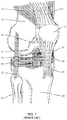
- FIG. 1 is provided with a brief explanation of the components of the knee.
- the knee may be composed of the quadriceps muscles 10, the femur 12, the articular cartilage 14, the lateral condyle 16, the posterior cruciate ligament 18, the anterior cruciate ligament 20, the lateral collateral ligament 22, the fibula 24, the tibia 26, the patellar tendon 28, the meniscus 30, the medial collateral ligament 32, the patella 34 (shown slightly displaced to the side - it normally rests in the center of the knee) and the quadriceps tendon 36.
- ACL anterior cruciate ligament
- ACL tears are common in athletes and are usually season ending injuries.
- the ACL 20 cannot heal - it must be surgically reconstructed.
- the reconstruction requires replacement tissue.
- the most common tissue used is a central slip of the patient's own patellar tendon 28.
- the patellar tendon 28 has proven to be generally effective, but the size of the graft that can be used is limited to the size of the patient's own patellar tendon 28.
- a third of the patellar tendon 28 may be harvested as a graft.
- a doctor will measure the width of the patellar tendon 28, divide by three, and take the middle third of the patellar tendon 28.
- Such harvested grafts are rarely more than 10 mm wide and may be smaller. Taking this tissue from a person's patellar tendon 28 also causes significant pain and discomfort in the post operative healing period, which may last up to a year, and up to twenty (20) percent of these patients are left with chronic anterior knee pain.
- cadaver grafts Some doctors recommend and use other graft sources, such as cadaver grafts, but cadaver grafts have a higher failure rate. Additionally, there is a non-zero chance of disease transmission or rejection by the patient's immune system. As a final drawback, cadaver grafts are usually quite expensive and may not be covered by some insurance companies.
- hamstring tendons e.g., the distal semitendinosus tendon
- the disadvantages include the fact that once the graft is taken, a patient's hamstring will never recover to its previous strength. Further, all hamstring reconstructions stretch and are looser than the original ACL 20. This loosening is particularly problematic in younger female athletes.
- quadriceps tendon 36 Another alternative graft source is the quadriceps tendon 36.
- the quadriceps tendon 36 is larger and stronger than either the patellar tendon 28 or the hamstring tendon.
- the quadriceps tendon 36 is likewise stiffer and less prone to stretching or plastic deformation.
- the qualities that make the quadriceps tendon 36 attractive also contribute to the difficulty in harvesting a graft from the quadriceps tendon 36.
- Existing surgical implements require a large incision up the longitudinal axis of the femur 12 on the front of the thigh to cut down to the level of the tendon 36, resulting in a large post operative scar.
- the quadriceps tendon 36 has a consistency similar to the proverbial shoe leather, making it difficult to cut.
- JP2010284478 which is considered to be the closest prior art, discloses a knife set capable of accurately incising the patellar tendon at a fixed width.
- the present disclosure provides a cutting implement as defined by claim 1 that is adapted to harvest a graft from the quadriceps tendon in a minimally invasive manner. Once the quadriceps tendon graft is secured, it may be used in conventional manners to repair the anterior cruciate ligament (ACL).
- the cutting implement comprises a handle portion and a blade portion.
- the first and second cutting surfaces form a point and define an aperture extending through the blade portion and are adapted to cut a quadriceps tendon and in so doing pass a cut portion of the quadriceps tendon through the aperture.
- the blade portion comprises a V-shaped cutting surface that is angled up and away from a distal point of the cutting surface. The space between the arms of the V is open allowing the harvested graft to pass therethrough.
- a top portion spans the distance between the tops of the arms of the V and helps isolate the quadriceps tendon from tissue that is positioned superiorly relative to the tendon.
- the top portion may comprise a cutting surface as well or the cutting implement may include a secondary cutting element that is adapted to cut the far end of the quadriceps tendon when a graft of a suitable length has been harvested.
- an auxiliary cutting device may be used to clip the far end of the tendon once the appropriate length has been stripped.
- the auxiliary cutting device may be a blade, scissors, or an electrocautery device in particularly contemplated embodiments.
- the cutting surface of the V-shaped cutting surface is serrated.
- spacers may be used to adjust the dimension of the cut.
- the spacers may be a polymeric material and placed between the tendon and the top element, effectively raising the top element away from the tendon, and thus narrowing the width of the V-shape cutting edge that is cutting the tendon.
- a second blade may be used that may fit inside the main blade.
- the second blade may move independently, reciprocating relative to the main blade so that the two blades operate like a scissor.
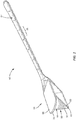
- FIGS 2-6 illustrate a first exemplary embodiment of a cutting implement 50 according to the present disclosure.
- the cutting implement 50 includes a handle portion 52 and a blade portion 54. Collectively, the handle portion 52 and blade portion 54 may have a longitudinal length of about ten inches (25.4 cm).
- the handle portion 52 may include indicia 56 disposed thereon that provide a measurement tool whose use will be explained in greater detail below.
- the handle portion 52 may be knurled (not shown), have finger indentations (not shown), or have other features to facilitate grasping of the handle portion 52, even during surgery when blood and other bodily fluids might otherwise make the handle portion 52 slippery.
- the blade portion 54 includes a first cutting surface 58 and a second cutting surface 60 joined to form a V-shape, with a point 62 and a wide portion 64.
- the two sides that form the cutting surfaces together define an aperture 66 that extends along the longitudinal axis of the cutting implement 50.
- the aperture 66 is closed on the top by a top portion 68 that extends across the wide portion 64 of the V-shape.
- the top portion 68 may include a cutting surface 70 that allows the cutting implement 50 to pass through tissue more readily. Manufacturing constraints may require the point 62 to be a tight curved tip instead of a true point, and as used herein "point" includes both a true point and such curved points.
- the top portion 68 extends over at least a portion of the cutting surfaces 58, 60.
- the cutting surfaces 58, 60 slant up and back from the point 62.
- At least the blade portion 54 is made of surgical grade steel and the cutting surfaces 58, 60 are honed to a high degree of sharpness comparable to that of a conventional scalpel.
- the cutting surfaces 58, 60 could be a synthetic diamond scalpel blade having a cutting width of approximately 3 nm or some form of cracked glass (e.g., obsidian), which may have cutting edges on the order of 200 Angstroms.
- Exemplary diamond scalpels are sold by Clinicon Corporation of Oceanside CA.
- Exemplary obsidian scalpels are sold by Fine Science Tools of Foster City CA.
- the cutting implement 50 may be part of a kit that includes the cutting implement 50, a cutting guide 72 ( Figs. 7-9 ), and a spacer 74 ( Fig. 15 ). Additionally, the kit may include an auxiliary cutting element such a pair of scissors or an electrocautery cutting element as described in greater detail below. This kit may be made as a single use kit, or the elements of the kit may support multiple sterilizations in an autoclave or comparable sterilization environment.
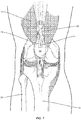
- the cutting guide 72 is illustrated in use in Figures 7-9 .
- the cutting guide may be generally trapezoidally shaped body 76 ( Fig. 9 ) and includes an optional handle 74 and posts 78.
- the bottom surface 80 of the body 76 may be about eleven (11) mm across, although other dimensions are also possible.
- the width of the bottom surface is slightly smaller than the width of the wide portion 64 of the blade portion 54 of the cutting implement 50.
- the sidewalls 82 are slanted such that if the sidewalls 82 were extended past the bottom surface 80, an equilateral triangle 84 is formed.
- a chisel or other cutting implement is placed next to the guide 72 and used to cut into the patella 34. The cuts made in this fashion cut an equilateral triangle bone plug 86 ( Fig. 11 ) that fits within the aperture 66 of the cutting implement 50.
- the guide 72 is removed, and surgical thread is threaded into the holes for the posts 78, the thread is then pulled up, effectively fishing the bone plug 86 out of the patella 34.
- the bone plug 86 is then fed into the aperture 66 and the cutting implement is ready to begin cutting (see Figure 10 ).
- the cutting implement 50 is then pushed anteriorly up the longitudinal axis of the femur 12, beneath the skin of the patient.
- the sharp cutting surfaces 58, 60 cut through the tough quadriceps tendon 36.
- the doctor may compare the length of harvested tendon 88 ( Fig. 11 ) to the indicia 56 to see if the doctor has harvested or stripped enough tendon 36.
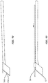
- Figure 12 illustrates an alternate embodiment wherein the cutting surfaces 58a, 60a are serrated. In some situations, the serrations may make it easier to cut the tough tendon 36.
- Figure 13 illustrates another alternate embodiment, wherein a selectively extendable blade 90 is positioned on the top portion 68.
- the extendable blade 90 may be used to sever the far end of the tendon 36 once an acceptable length of tendon has been harvested.
- the blade 90 In a first, retracted position the blade 90 may be positioned within a sheath.
- the blade 90 In a second, extended position, the blade 90 may be exposed and extend past the front of the top surface 68 such that the blade is approximately as far forward as the distal point 62.
- Figure 15 illustrates a spacer 92, which in an exemplary embodiment comprises a polymeric washer shape approximately 1 mm thick.
- the spacer 92 may be positioned underneath the top surface 68 on the tendon 36. Because the aperture 66 is an equilateral triangle, each spacer 92 effectively lifts the cutting surfaces 58, 60 an equal distance and effectively narrows the amount of tendon 36 that is harvested. For example, if the wide portion 64 is eleven mm wide, one spacer 92 would lift the blades one mm, causing the widest cutting part to now be ten mm. Additional spacers 92 may be stacked to reduce the width of the harvesting further as needed.
- FIGS 16A and 16B illustrate another alternate embodiment wherein the cutting implement 50A has a scissor-like cutting portion 54A.
- the cutting portion 54a includes primary cutting surfaces 58A, 60A and reciprocating V-shaped cutting surface 94 that moves relative to the primary cutting surfaces 58A, 60A.
- the cutting surface 94 moves up and down in a generally arcuate motion (generally indicated at 96), and the cutting effect is achieved as the blades close, similar to conventional scissors.
- the cutting surface 94 moves along the longitudinal axis of the cutting implement 50A (generally indicated at 98) so that the cutting surface 94 moves in and out of the aperture 66.
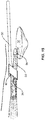
- FIG 17 illustrates an auxiliary cutting element 150 that is used to sever the distal end of the quadriceps tendon 36.
- the auxiliary cutting element 150 may be an electrocautery element shaped like a cylinder 152 with a short axis 154 and an insulated, rotating cautery tip 156 selectively extendable at a distal end of the element 150.
- the cutting element 50 is used to strip a section of the tendon 36. Then the cutting element 50 is withdrawn, and the bone plug 86 and the harvested tendon 88 are fed through the cylinder 152 of the auxiliary cutting element 150.
- the cautery tip 156 is then simultaneously extended, rotated, and heated (or heated and extended and rotated).
- the cautery tip 156 rotates inwardly towards the center of the cylinder 152.
- the auxiliary cutting element 150 is rotated about the harvested tendon 88, moving the extended cautery tip 156 through the distal end of the harvested tendon 88. This movement effectively cuts the tendon 88 at the far point and is believed to be less invasive than simply advancing the cutting implement 50 to the end of the tendon 36 and into the muscle (which would effectively "tear" the harvested tendon 88 from the attached fibers and the quadriceps).
- a cutting implement could take the form of a pair of scissors such as a modified pair of OB-GYN scissors.
- the scissors may be modified so that the hinge is more in the middle of the scissor than is typical. By moving the hinge, the scissors can be used deep in the wound, keeping the incision small. Still other cutting implements could be used to sever the distal end of the harvested tendon 88 as desired.
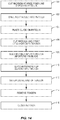
- Figure 14 illustrates a flow chart explaining use of the cutting implement 50.
- the doctor makes an initial incision at a knee fold line (block 100), such as an anterior fold line, and folds the skin back to expose a portion of the patella 34.
- the doctor drills two post holes into the patella 34 proximate the quadriceps tendon 36 (block 102).
- the holes may be approximately eleven mm deep in an exemplary embodiment.
- the doctor then places the guide 74 on the patella 34, with the posts 78 positioned within the holes (block 104).
- the doctor will chose the width of the quadriceps tendon to be harvested by measuring the size of the quadriceps tendon preoperatively from MRI imaging and comparing them to the intraoperative observations of the tendon itself.
- Cross sectional area of the patellar tendon can be calculated from the MRI, and one third this patellar tendon area can be compared to the cross sectional areas resulting from different quadriceps options based on the areas of the equilateral triangles resulting.
- the bone plug 86 is created by cutting into the patella 34 using the sidewalls of the guide 74 to guide the cuts into the patella 34, thereby creating the equilateral bone plug 86 and the initial cut into the quadriceps tendon 36 (block 106).
- the guide 74 directs the saw blade such that the resulting bone plug 86 is of the same dimensions as the quadriceps graft that has been chosen, allowing it to be slipped through the aperture 66 on the blade portion 54 (block 108).
- the graft may be secured by sutures based through the original holes drilled at the beginning of the procedure, facilitating passage of the bone plug 86.
- the doctor inserts one or more spacers 92 to space the top surface 68 from the tendon 36, narrowing the cutting width.
- the doctor slices anteriorly up the quadriceps tendon 36 underneath the skin of the patient (block 110).
- the doctor severs the distal end of the tendon 36 (block 112), such as by rotating the top portion 68 into contact with the tendon 36 and sawing, or selectively extending the extendable blade 90 and using it to saw through the tendon 36.
- a second blade may be inserted through the incision and used to cut the distal end of the tendon 36.
- the doctor may insert the auxiliary cutting implement 150, extend the cautery tip 156 and cauterize the end of the tendon 36. Still another option is to make a new incision further up the thigh proximate the distal end and make a cut into the tendon 36 at the second incision. The doctor then removes the tendon (block 114) and closes the incision (block 116).
Description
- The present disclosure relates to a cutting instrument adapted to help a surgeon harvest a replacement tendon for an anterior cruciate ligament (ACL) injury from the quadriceps tendon.
- Most people can go through the majority of their life without ever caring or knowing how complicated a structure the knee that helps them walk is. However, the knee remains a fragile mechanical structure that is readily susceptible to damage. While medical advances have made repairing the knee possible, repair of certain types of injuries results in other long term effects. To assist the reader in appreciating the elegance of the present disclosure,
Figure 1 is provided with a brief explanation of the components of the knee. - For the purposes of the present disclosure, and as illustrated, the knee may be composed of the
quadriceps muscles 10, thefemur 12, thearticular cartilage 14, thelateral condyle 16, theposterior cruciate ligament 18, theanterior cruciate ligament 20, thelateral collateral ligament 22, thefibula 24, thetibia 26, thepatellar tendon 28, themeniscus 30, themedial collateral ligament 32, the patella 34 (shown slightly displaced to the side - it normally rests in the center of the knee) and thequadriceps tendon 36. Of particular interest for the purposes of the present disclosure is the anterior cruciate ligament (ACL) 20 and what is done to repair theACL 20. - ACL tears are common in athletes and are usually season ending injuries. The ACL 20 cannot heal - it must be surgically reconstructed. The reconstruction requires replacement tissue. The most common tissue used is a central slip of the patient's own
patellar tendon 28. In practice, thepatellar tendon 28 has proven to be generally effective, but the size of the graft that can be used is limited to the size of the patient's ownpatellar tendon 28. As a rule of thumb, only a third of thepatellar tendon 28 may be harvested as a graft. Thus, a doctor will measure the width of thepatellar tendon 28, divide by three, and take the middle third of thepatellar tendon 28. Such harvested grafts are rarely more than 10 mm wide and may be smaller. Taking this tissue from a person'spatellar tendon 28 also causes significant pain and discomfort in the post operative healing period, which may last up to a year, and up to twenty (20) percent of these patients are left with chronic anterior knee pain. - Some doctors recommend and use other graft sources, such as cadaver grafts, but cadaver grafts have a higher failure rate. Additionally, there is a non-zero chance of disease transmission or rejection by the patient's immune system. As a final drawback, cadaver grafts are usually quite expensive and may not be covered by some insurance companies.
- Other doctors use hamstring tendons (e.g., the distal semitendinosus tendon) because the scar created during harvesting is relatively small and there is less pain during the rehabilitation, but again, the hamstring tendon has its own collection of disadvantages. The disadvantages include the fact that once the graft is taken, a patient's hamstring will never recover to its previous strength. Further, all hamstring reconstructions stretch and are looser than the
original ACL 20. This loosening is particularly problematic in younger female athletes. - Another alternative graft source is the
quadriceps tendon 36. Thequadriceps tendon 36 is larger and stronger than either thepatellar tendon 28 or the hamstring tendon. Thequadriceps tendon 36 is likewise stiffer and less prone to stretching or plastic deformation. However, the qualities that make thequadriceps tendon 36 attractive also contribute to the difficulty in harvesting a graft from thequadriceps tendon 36. Existing surgical implements require a large incision up the longitudinal axis of thefemur 12 on the front of the thigh to cut down to the level of thetendon 36, resulting in a large post operative scar. Additionally, thequadriceps tendon 36 has a consistency similar to the proverbial shoe leather, making it difficult to cut. However, an ACL 20 repaired with grafts from thequadriceps tendon 36 generally result in almost no anterior knee pain postoperatively over the short or long term and recover quicker. The difficulties in harvesting aquadriceps tendon 36 led to the present disclosure's exploration of an alternate modality for harvesting a graft from thequadriceps tendon 36.US2011/004214 discloses an osteotome having a V-shaped cutting member with a stop bar across it to limit the depth to which the instrument can be driven into bone. -
JP2010284478 - The present disclosure provides a cutting implement as defined by claim 1 that is adapted to harvest a graft from the quadriceps tendon in a minimally invasive manner. Once the quadriceps tendon graft is secured, it may be used in conventional manners to repair the anterior cruciate ligament (ACL). The cutting implement comprises a handle portion and a blade portion. In addition, the first and second cutting surfaces form a point and define an aperture extending through the blade portion and are adapted to cut a quadriceps tendon and in so doing pass a cut portion of the quadriceps tendon through the aperture. The blade portion comprises a V-shaped cutting surface that is angled up and away from a distal point of the cutting surface. The space between the arms of the V is open allowing the harvested graft to pass therethrough. A top portion spans the distance between the tops of the arms of the V and helps isolate the quadriceps tendon from tissue that is positioned superiorly relative to the tendon.
- In alternate embodiments, the top portion may comprise a cutting surface as well or the cutting implement may include a secondary cutting element that is adapted to cut the far end of the quadriceps tendon when a graft of a suitable length has been harvested. In still another embodiment, an auxiliary cutting device may be used to clip the far end of the tendon once the appropriate length has been stripped. The auxiliary cutting device may be a blade, scissors, or an electrocautery device in particularly contemplated embodiments. In another alternate but not mutually exclusive embodiment, the cutting surface of the V-shaped cutting surface is serrated.
- In another non-exclusive, alternate embodiment, spacers may be used to adjust the dimension of the cut. The spacers may be a polymeric material and placed between the tendon and the top element, effectively raising the top element away from the tendon, and thus narrowing the width of the V-shape cutting edge that is cutting the tendon.
- In another embodiment, a second blade may be used that may fit inside the main blade. The second blade may move independently, reciprocating relative to the main blade so that the two blades operate like a scissor.
- Those skilled in the art will appreciate the scope of the disclosure and realize additional aspects thereof after reading the following detailed description in association with the accompanying drawings.
- The accompanying drawings incorporated in and forming a part of this specification illustrate several aspects of the disclosure, and together with the description serve to explain the principles of the disclosure.
-
Figure 1 illustrates a conventional knee; -
Figure 2 illustrates a perspective view of an exemplary embodiment of the cutting implement of the present disclosure; -
Figure 3 illustrates a side elevational view of an exemplary embodiment of the cutting implement of the present disclosure; -
Figure 4 illustrates a front elevational view of the cutting implement ofFigure 3 ; -
Figure 5 illustrates a back elevational view of the cutting implement ofFigure 3 ; -
Figure 6 illustrates a top plan view of the cutting implement ofFigure 3 ; -
Figure 7 illustrates a knee with a bone graft guide positioned thereon as is done at the beginning of tendon harvesting; -
Figures 8 and 9 illustrate the bone graft guide positioned on the patella as is used to form the bone graft; -
Figure 10 illustrates the cutting implement beginning to cut the quadriceps tendon; -
Figure 11 illustrates the cutting implement with a portion of the harvested graft extending from the back end of the cutting implement; -
Figure 12 illustrates an alternate embodiment with a serrated blade; -
Figure 13 illustrates another alternate embodiment with a distinct and selectively extendable distal cutting element; -
Figure 14 illustrates a flow chart setting forth an exemplary method of using the cutting implement of the present disclosure; -
Figure 15 illustrates spacers that may be used to control the width of the cut. -
Figures 16A and 16B illustrate an embodiment with a scissor type cutting element; and -
Figure 17 illustrates an electrocautery tip auxiliary cutting element. - The embodiments set forth below represent the necessary information to enable those skilled in the art to practice the disclosure and illustrate the best mode of practicing the disclosure. Upon reading the following description in light of the accompanying drawings, those skilled in the art will understand the concepts of the disclosure and will recognize applications of these concepts not particularly addressed herein. It should be understood that these concepts and applications fall within the scope of the disclosure and the accompanying claims.
-
Figures 2-6 illustrate a first exemplary embodiment of a cutting implement 50 according to the present disclosure. The cutting implement 50 includes ahandle portion 52 and ablade portion 54. Collectively, thehandle portion 52 andblade portion 54 may have a longitudinal length of about ten inches (25.4 cm). Thehandle portion 52 may includeindicia 56 disposed thereon that provide a measurement tool whose use will be explained in greater detail below. Thehandle portion 52 may be knurled (not shown), have finger indentations (not shown), or have other features to facilitate grasping of thehandle portion 52, even during surgery when blood and other bodily fluids might otherwise make thehandle portion 52 slippery. - The
blade portion 54 includes afirst cutting surface 58 and asecond cutting surface 60 joined to form a V-shape, with apoint 62 and awide portion 64. The two sides that form the cutting surfaces together define anaperture 66 that extends along the longitudinal axis of the cutting implement 50. Theaperture 66 is closed on the top by atop portion 68 that extends across thewide portion 64 of the V-shape. Thetop portion 68 may include a cuttingsurface 70 that allows the cutting implement 50 to pass through tissue more readily. Manufacturing constraints may require thepoint 62 to be a tight curved tip instead of a true point, and as used herein "point" includes both a true point and such curved points. - As better seen in
Figures 3 and 6 , thetop portion 68 extends over at least a portion of the cutting surfaces 58, 60. Likewise, as better seen inFigure 3 , the cutting surfaces 58, 60 slant up and back from thepoint 62. - In an exemplary embodiment, at least the
blade portion 54 is made of surgical grade steel and the cutting surfaces 58, 60 are honed to a high degree of sharpness comparable to that of a conventional scalpel. Alternatively, the cutting surfaces 58, 60 could be a synthetic diamond scalpel blade having a cutting width of approximately 3 nm or some form of cracked glass (e.g., obsidian), which may have cutting edges on the order of 200 Angstroms. Exemplary diamond scalpels are sold by Clinicon Corporation of Oceanside CA. Exemplary obsidian scalpels are sold by Fine Science Tools of Foster City CA. - The cutting implement 50 may be part of a kit that includes the cutting implement 50, a cutting guide 72 (
Figs. 7-9 ), and a spacer 74 (Fig. 15 ). Additionally, the kit may include an auxiliary cutting element such a pair of scissors or an electrocautery cutting element as described in greater detail below. This kit may be made as a single use kit, or the elements of the kit may support multiple sterilizations in an autoclave or comparable sterilization environment. - The cutting
guide 72 is illustrated in use inFigures 7-9 . The cutting guide may be generally trapezoidally shaped body 76 (Fig. 9 ) and includes anoptional handle 74 and posts 78. Thebottom surface 80 of thebody 76 may be about eleven (11) mm across, although other dimensions are also possible. In an exemplary embodiment, the width of the bottom surface is slightly smaller than the width of thewide portion 64 of theblade portion 54 of the cutting implement 50. Furthermore, thesidewalls 82 are slanted such that if thesidewalls 82 were extended past thebottom surface 80, anequilateral triangle 84 is formed. In use, a chisel or other cutting implement is placed next to theguide 72 and used to cut into thepatella 34. The cuts made in this fashion cut an equilateral triangle bone plug 86 (Fig. 11 ) that fits within theaperture 66 of the cutting implement 50. - Once the
bone plug 86 has been cut, theguide 72 is removed, and surgical thread is threaded into the holes for theposts 78, the thread is then pulled up, effectively fishing thebone plug 86 out of thepatella 34. When selecting the place from which to create thebone plug 86, at least a portion of thebone plug 86 should be attached to thequadriceps tendon 36. Thus, when thebone plug 86 is extracted from thepatella 34, it is still attached to thequadriceps tendon 36. Thebone plug 86 is then fed into theaperture 66 and the cutting implement is ready to begin cutting (seeFigure 10 ). The cutting implement 50 is then pushed anteriorly up the longitudinal axis of thefemur 12, beneath the skin of the patient. The sharp cutting surfaces 58, 60 cut through thetough quadriceps tendon 36. The doctor may compare the length of harvested tendon 88 (Fig. 11 ) to theindicia 56 to see if the doctor has harvested or strippedenough tendon 36. -
Figure 12 illustrates an alternate embodiment wherein the cutting surfaces 58a, 60a are serrated. In some situations, the serrations may make it easier to cut thetough tendon 36. -
Figure 13 illustrates another alternate embodiment, wherein a selectivelyextendable blade 90 is positioned on thetop portion 68. Theextendable blade 90 may be used to sever the far end of thetendon 36 once an acceptable length of tendon has been harvested. In a first, retracted position theblade 90 may be positioned within a sheath. In a second, extended position, theblade 90 may be exposed and extend past the front of thetop surface 68 such that the blade is approximately as far forward as thedistal point 62. -
Figure 15 illustrates aspacer 92, which in an exemplary embodiment comprises a polymeric washer shape approximately 1 mm thick. Thespacer 92 may be positioned underneath thetop surface 68 on thetendon 36. Because theaperture 66 is an equilateral triangle, eachspacer 92 effectively lifts the cutting surfaces 58, 60 an equal distance and effectively narrows the amount oftendon 36 that is harvested. For example, if thewide portion 64 is eleven mm wide, onespacer 92 would lift the blades one mm, causing the widest cutting part to now be ten mm.Additional spacers 92 may be stacked to reduce the width of the harvesting further as needed. -
Figures 16A and 16B illustrate another alternate embodiment wherein the cutting implement 50A has a scissor-like cutting portion 54A. As illustrated, the cutting portion 54a includes primary cutting surfaces 58A, 60A and reciprocating V-shapedcutting surface 94 that moves relative to the primary cutting surfaces 58A, 60A. In a first embodiment, the cuttingsurface 94 moves up and down in a generally arcuate motion (generally indicated at 96), and the cutting effect is achieved as the blades close, similar to conventional scissors. In a second embodiment, the cuttingsurface 94 moves along the longitudinal axis of the cutting implement 50A (generally indicated at 98) so that the cuttingsurface 94 moves in and out of theaperture 66. -
Figure 17 illustrates anauxiliary cutting element 150 that is used to sever the distal end of thequadriceps tendon 36. Theauxiliary cutting element 150 may be an electrocautery element shaped like acylinder 152 with ashort axis 154 and an insulated,rotating cautery tip 156 selectively extendable at a distal end of theelement 150. In practice, the cuttingelement 50 is used to strip a section of thetendon 36. Then the cuttingelement 50 is withdrawn, and thebone plug 86 and the harvestedtendon 88 are fed through thecylinder 152 of theauxiliary cutting element 150. Thecautery tip 156 is then simultaneously extended, rotated, and heated (or heated and extended and rotated). Thecautery tip 156 rotates inwardly towards the center of thecylinder 152. Theauxiliary cutting element 150 is rotated about the harvestedtendon 88, moving theextended cautery tip 156 through the distal end of the harvestedtendon 88. This movement effectively cuts thetendon 88 at the far point and is believed to be less invasive than simply advancing the cutting implement 50 to the end of thetendon 36 and into the muscle (which would effectively "tear" the harvestedtendon 88 from the attached fibers and the quadriceps). Cautery elements are known and can be adapted from those sold by websites such as www.dremed.com/catalog/product_info.php/cPath/45_78/products_id/421 and www.orsupply.com/medical/category/Cautery+Electrodes/489. - In another embodiment, not specifically illustrated, a cutting implement could take the form of a pair of scissors such as a modified pair of OB-GYN scissors. In particular, the scissors may be modified so that the hinge is more in the middle of the scissor than is typical. By moving the hinge, the scissors can be used deep in the wound, keeping the incision small. Still other cutting implements could be used to sever the distal end of the harvested
tendon 88 as desired. -
Figure 14 illustrates a flow chart explaining use of the cutting implement 50. The doctor makes an initial incision at a knee fold line (block 100), such as an anterior fold line, and folds the skin back to expose a portion of thepatella 34. The doctor drills two post holes into thepatella 34 proximate the quadriceps tendon 36 (block 102). The holes may be approximately eleven mm deep in an exemplary embodiment. The doctor then places theguide 74 on thepatella 34, with theposts 78 positioned within the holes (block 104). The doctor will chose the width of the quadriceps tendon to be harvested by measuring the size of the quadriceps tendon preoperatively from MRI imaging and comparing them to the intraoperative observations of the tendon itself. Cross sectional area of the patellar tendon can be calculated from the MRI, and one third this patellar tendon area can be compared to the cross sectional areas resulting from different quadriceps options based on the areas of the equilateral triangles resulting. - Next the
bone plug 86 is created by cutting into thepatella 34 using the sidewalls of theguide 74 to guide the cuts into thepatella 34, thereby creating theequilateral bone plug 86 and the initial cut into the quadriceps tendon 36 (block 106). Theguide 74 directs the saw blade such that the resulting bone plug 86 is of the same dimensions as the quadriceps graft that has been chosen, allowing it to be slipped through theaperture 66 on the blade portion 54 (block 108). The graft may be secured by sutures based through the original holes drilled at the beginning of the procedure, facilitating passage of thebone plug 86. If necessary, the doctor inserts one ormore spacers 92 to space thetop surface 68 from thetendon 36, narrowing the cutting width. The doctor then slices anteriorly up thequadriceps tendon 36 underneath the skin of the patient (block 110). When an appropriate length oftendon 36 has been cut, the doctor severs the distal end of the tendon 36 (block 112), such as by rotating thetop portion 68 into contact with thetendon 36 and sawing, or selectively extending theextendable blade 90 and using it to saw through thetendon 36. Alternatively, a second blade may be inserted through the incision and used to cut the distal end of thetendon 36. As still another option, the doctor may insert the auxiliary cutting implement 150, extend thecautery tip 156 and cauterize the end of thetendon 36. Still another option is to make a new incision further up the thigh proximate the distal end and make a cut into thetendon 36 at the second incision. The doctor then removes the tendon (block 114) and closes the incision (block 116). - Those skilled in the art will recognize improvements and modifications to the embodiments of the present disclosure. All such improvements and modifications are considered within the scope of the concepts disclosed herein and the claims that follow.
Claims (12)
- A surgical instrument (50) comprising:a handle portion (52); anda blade portion (54) joined to the handle portion, the blade portion comprising:a first cutting surface(58);a second cutting surface (60) joined to the first cutting surface to form a V-shape having a wide portion (64) ; anda top portion (68) extending across the wide portion of the V-shape, wherein the first and second cutting surfaces form a point (62) and define an aperture (66) extending through the blade portion and are adapted to cut a quadriceps tendon and in so doing pass a cut portion of the quadriceps tendon through the aperture (66).
- The surgical instrument of claim 1 wherein the blade portion comprises a steel blade portion.
- The surgical instrument of claim 1 wherein the first and second cutting surfaces comprise serrated cutting surfaces (58a, 60a).
- The surgical instrument of claim 1 further comprising a spacer (92) selectively positionable beneath the top portion to space the top portion from a work piece being cut by the first and second cutting surfaces.
- The surgical instrument of claim 1 further comprising a third cutting surface (90) movably positioned on the top portion (68) such that in a first position the third cutting surface extends past a front edge of the top portion and is available to cut and in a second position the third cutting surface is retracted and not available to cut.
- The surgical instrument of claim 1 wherein the top portion does not include a cutting surface.
- The surgical instrument of claim 1 further comprising a second cutting element (90) positioned within the blade portion and adapted to reciprocate along a longitudinal axis of the surgical instrument.
- A surgical kit comprising:a surgical instrument according to Claim 1 or 3;a spacer; anda guide adapted to assist a surgeon in creating a bone plug extract from a patella.
- The surgical kit of claim 8 wherein the spacer (92) is adapted to fit underneath the top portion (68) and space the top portion from the quadriceps tendon while the cutting surfaces are cutting the quadriceps tendon.
- The surgical kit of claim 8 wherein the guide comprises at least one post (78) adapted to be positioned within a hole in the patella.
- The surgical kit of claim 8 wherein the spacer (92) comprises a polymeric material.
- The surgical instrument of claim 1, wherein the first and second cutting surfaces slant up and back from the point and the top portion (68) has a handle side proximate the handle portion and a front edge opposite the handle side, and the point of the blade portion extends away from the handle portion past the front edge of the top portion.
Applications Claiming Priority (2)
| Application Number | Priority Date | Filing Date | Title |
|---|---|---|---|
| US13/102,562 US8894672B2 (en) | 2011-05-06 | 2011-05-06 | Quadriceps tendon stripper |
| PCT/US2012/036728 WO2012154643A2 (en) | 2011-05-06 | 2012-05-07 | Quadriceps tendon stripper |
Publications (3)
| Publication Number | Publication Date |
|---|---|
| EP2704649A2 EP2704649A2 (en) | 2014-03-12 |
| EP2704649A4 EP2704649A4 (en) | 2015-01-14 |
| EP2704649B1 true EP2704649B1 (en) | 2018-04-04 |
Family
ID=47090764
Family Applications (1)
| Application Number | Title | Priority Date | Filing Date |
|---|---|---|---|
| EP12782646.9A Not-in-force EP2704649B1 (en) | 2011-05-06 | 2012-05-07 | Quadriceps tendon stripper |
Country Status (6)
| Country | Link |
|---|---|
| US (3) | US8894672B2 (en) |
| EP (1) | EP2704649B1 (en) |
| JP (1) | JP2014519879A (en) |
| BR (1) | BR112013028474B1 (en) |
| MX (1) | MX342973B (en) |
| WO (1) | WO2012154643A2 (en) |
Families Citing this family (21)
| Publication number | Priority date | Publication date | Assignee | Title |
|---|---|---|---|---|
| US8894672B2 (en) * | 2011-05-06 | 2014-11-25 | Paul Leach Burroughs, III | Quadriceps tendon stripper |
| US8894676B2 (en) | 2012-06-11 | 2014-11-25 | Paul Leach Burroughs, III | Tubular ligament cutting implement |
| CN103006277B (en) * | 2013-01-07 | 2014-07-30 | 王燕杰 | Tendon taking machine |
| WO2015127205A1 (en) * | 2014-02-20 | 2015-08-27 | Boston Scientific Scimed, Inc. | Peelable sheath |
| EP3410944B1 (en) * | 2016-02-02 | 2023-06-07 | Dermazip AB | Biopsy incision device |
| CN106691546B (en) * | 2017-01-11 | 2020-08-07 | 刘波 | Dissector for cutting costal cartilage junction |
| CN110573091A (en) * | 2017-03-15 | 2019-12-13 | 史密夫和内修有限公司 | Graft preparation and delivery apparatus and methods |
| CN106943177B (en) * | 2017-05-04 | 2019-09-03 | 延安大学附属医院 | A kind of cutter device for treating discoid meniscus tearing |
| ES2950727T3 (en) * | 2018-09-13 | 2023-10-13 | Medacta Int Sa | Cutting tool for vertical tendon incision |
| ES2907223T3 (en) * | 2018-09-13 | 2022-04-22 | Medacta Int Sa | Cutting tool for horizontal incision of a tendon |
| ES2949872T3 (en) * | 2018-09-13 | 2023-10-03 | Medacta Int Sa | Tool for subcutaneous tendon cutting |
| US11871940B2 (en) | 2018-11-27 | 2024-01-16 | Sunnybrook Research Institute | Cartilage slicing apparatus and methods therefor |
| EP3756554A1 (en) * | 2019-05-25 | 2020-12-30 | Georg Barth | Excision scalpel |
| US20200390463A1 (en) | 2019-06-14 | 2020-12-17 | Quadvantage Technology, Inc. | Dual-blade tendon cutting apparatus and cartridge for multiple apparatuses |
| US11376022B2 (en) | 2019-07-18 | 2022-07-05 | Quadvantage Technology, Inc. | Patella cutting guide |
| US20220409192A1 (en) * | 2019-10-17 | 2022-12-29 | Smith & Nephew, Inc. | Tendon haarvesting assemblies and methods |
| US11160576B1 (en) * | 2020-06-29 | 2021-11-02 | The United States Of America As Represented By The Secretary Of The Navy | Amputation system for field use |
| RU206061U1 (en) * | 2020-07-21 | 2021-08-18 | федеральное государственное бюджетное образовательное учреждение высшего образования "Московский государственный медико-стоматологический университет имени А.И. Евдокимова" Министерства здравоохранения Российской Федерации (ФГБОУ ВО МГМСУ им. А.И. Евдокимова Минздрава России) | STRIPPER FOR EXTRACTION OF THE CALFRONAL NERVE IN CHILDREN |
| US11779317B2 (en) | 2021-03-09 | 2023-10-10 | Arthrex, Inc. | Surgical device configured to strip and cut tendon |
| US20220370091A1 (en) | 2021-05-18 | 2022-11-24 | Quadvantage Technology, Inc. | Surgical cutting blade using composite materials |
| US20230099684A1 (en) | 2021-09-27 | 2023-03-30 | Quadvantage Technology, Inc. | Dual-blade tendon cutting apparatus |
Family Cites Families (70)
| Publication number | Priority date | Publication date | Assignee | Title |
|---|---|---|---|---|
| US622461A (en) * | 1899-04-04 | Sanne | ||
| US3583390A (en) | 1968-08-12 | 1971-06-08 | Mario Enrique Jascalevich | Biopsy device |
| US3844272A (en) | 1969-02-14 | 1974-10-29 | A Banko | Surgical instruments |
| US3815604A (en) | 1972-06-19 | 1974-06-11 | Malley C O | Apparatus for intraocular surgery |
| US3902498A (en) | 1974-03-04 | 1975-09-02 | Minnesota Mining & Mfg | Surgical cutting instrument |
| US4099529A (en) | 1976-09-20 | 1978-07-11 | Peyman Gholam A | Wide-angle cutter vitrophage |
| US4461305A (en) | 1981-09-04 | 1984-07-24 | Cibley Leonard J | Automated biopsy device |
| US4696298A (en) | 1985-11-19 | 1987-09-29 | Storz Instrument Company | Vitrectomy cutting mechanism |
| US4773417A (en) | 1987-01-05 | 1988-09-27 | Moore Robert R | Method for using a tendon stripper and leader set |
| US4832045A (en) | 1988-03-18 | 1989-05-23 | Goldberger Robert E | Biopsy instrument |
| DE8903079U1 (en) * | 1989-03-13 | 1989-05-11 | Weba Medizinmechanik, 7201 Balgheim, De | |
| US5226910A (en) | 1989-07-05 | 1993-07-13 | Kabushiki Kaisha Topcon | Surgical cutter |
| US5112299A (en) | 1989-10-25 | 1992-05-12 | Hall Surgical Division Of Zimmer, Inc. | Arthroscopic surgical apparatus and method |
| US5505210A (en) | 1989-11-06 | 1996-04-09 | Mectra Labs, Inc. | Lavage with tissue cutting cannula |
| US4985031A (en) * | 1989-12-28 | 1991-01-15 | Techmedica, Inc. | Left and right inferior border osteotomy blade saw |
| US5007917A (en) | 1990-03-08 | 1991-04-16 | Stryker Corporation | Single blade cutter for arthroscopic surgery |
| FR2665628B1 (en) * | 1990-08-10 | 1993-08-06 | Cendis Medical | APPARATUS FOR TAKING A JOINT TENDON. |
| AU648107B2 (en) | 1990-08-20 | 1994-04-14 | Suri A. Sastri | Tubular surgical cutting instruments |
| US5267572A (en) | 1990-11-20 | 1993-12-07 | Bucalo Brian D | Biopsy instrument with tissue specimen retaining and retrieval device |
| US5285795A (en) | 1991-09-12 | 1994-02-15 | Surgical Dynamics, Inc. | Percutaneous discectomy system having a bendable discectomy probe and a steerable cannula |
| US5391169A (en) | 1991-12-13 | 1995-02-21 | Mcguire; David A. | Patellar tendon harvester |
| US5269798A (en) | 1992-02-19 | 1993-12-14 | Linvatec Corporation | Surgical cutting instrument with movable, inner and outer tubular members |
| WO1994002075A1 (en) | 1992-07-15 | 1994-02-03 | University Of Miami | Surgical cutting heads |
| US5549618A (en) | 1994-01-18 | 1996-08-27 | Coral Medical | Knot tying method and apparatus |
| US5496325A (en) | 1994-08-09 | 1996-03-05 | Mclees; Donald J. | Split stem surgical saw blade |
| US5570700A (en) | 1994-10-03 | 1996-11-05 | Vogeler; Douglas M. | Elliptical biopsy punch |
| US5807277A (en) | 1995-12-15 | 1998-09-15 | Swaim; William R. | Biopsy hand tool for capturing tissue sample |
| US5722977A (en) * | 1996-01-24 | 1998-03-03 | Danek Medical, Inc. | Method and means for anterior lumbar exact cut with quadrilateral osteotome and precision guide/spacer |
| US5665101A (en) | 1996-04-01 | 1997-09-09 | Linvatec Corporation | Endoscopic or open lipectomy instrument |
| US5693063A (en) | 1996-04-10 | 1997-12-02 | Bristol-Myers Squibb Company | Process for shaping and sharpening a rotatable surgical shaver blade |
| WO1998019610A1 (en) | 1996-11-05 | 1998-05-14 | Mcguire David A | Device and method for tendon harvesting |
| US5893862A (en) | 1997-04-10 | 1999-04-13 | Pratt; Arthur William | Surgical apparatus |
| CA2219468C (en) | 1997-12-22 | 2001-04-17 | Andrew Dewberry | Caulk bead removal tool |
| US6033375A (en) | 1997-12-23 | 2000-03-07 | Fibrasonics Inc. | Ultrasonic probe with isolated and teflon coated outer cannula |
| US5933968A (en) * | 1998-04-06 | 1999-08-10 | Solomon; Anna | Pumpkin cutter |
| US6241769B1 (en) * | 1998-05-06 | 2001-06-05 | Cortek, Inc. | Implant for spinal fusion |
| JP2920167B1 (en) * | 1998-06-10 | 1999-07-19 | 英卓 高 | Medical bone plug cutter |
| US6030400A (en) | 1998-10-16 | 2000-02-29 | Johnson; Lanny L. | Articular cartilage harvesting knife |
| US6428539B1 (en) | 2000-03-09 | 2002-08-06 | Origin Medsystems, Inc. | Apparatus and method for minimally invasive surgery using rotational cutting tool |
| US6391031B1 (en) * | 2001-05-17 | 2002-05-21 | Eugene P. Toomey | Device for the repair of a hallux valgus deformity |
| US6632225B2 (en) | 2001-06-20 | 2003-10-14 | Zimmer, Inc. | Method and apparatus for resecting a distal femur and a proximal tibia in preparation for implanting a partial knee prosthesis |
| AU2003226382A1 (en) * | 2002-04-12 | 2003-10-27 | Eric S. Steenlage | Method and apparatus for reconstructing a ligament |
| US7163547B2 (en) | 2003-04-23 | 2007-01-16 | Heshmat Majlessi | Harvester |
| US7144403B2 (en) * | 2003-07-29 | 2006-12-05 | Alcon, Inc. | Surgical knife |
| US20050149092A1 (en) | 2003-09-16 | 2005-07-07 | University Of Massachusetts Medical School | Dermal punch device |
| JP4790234B2 (en) | 2004-07-01 | 2011-10-12 | 株式会社ニデック | Vitreous cutter |
| US20060111722A1 (en) | 2004-11-19 | 2006-05-25 | Hacene Bouadi | Surgical cutting tool |
| US20060212060A1 (en) | 2005-02-11 | 2006-09-21 | Arthrex, Inc. | Arthroscopic shaver and method of manufacturing same |
| US20060212057A1 (en) | 2005-03-18 | 2006-09-21 | Ilija Djordjevic | Miniature surgical scalpel with integral protection shield |
| US7320687B2 (en) | 2005-05-04 | 2008-01-22 | Lee Thomas H | Tendon stripper |
| US8177803B2 (en) | 2006-07-19 | 2012-05-15 | Target Medical Innovations, LLC | Endoscopic cutting instruments having improved cutting efficiency and reduced manufacturing costs |
| US7666200B2 (en) | 2006-07-19 | 2010-02-23 | Target Medical Innovations Llc | Endoscopic cutting instrument with axial and rotary motion |
| WO2008019097A2 (en) | 2006-08-03 | 2008-02-14 | The Cleveland Clinic Foundation | An apparatus for cutting tissue |
| US20080065113A1 (en) | 2006-09-11 | 2008-03-13 | Smith Dean W | Suture cutter and remover |
| US20080161810A1 (en) * | 2006-10-18 | 2008-07-03 | Warsaw Orthopedic, Inc. | Guide and Cutter for Contouring Facet Joints and Methods of Use |
| US8430896B2 (en) | 2007-01-31 | 2013-04-30 | Kurume University | Surgical appliance for use in taking out transplant-use tendon and in regenerating operation of tendon at location where transplant tendon was taken out |
| WO2008128186A1 (en) | 2007-04-12 | 2008-10-23 | Applied Medical Resources Corporation | Method and apparatus for tissue morcellation |
| US8048079B2 (en) | 2007-06-07 | 2011-11-01 | Arthrex, Inc. | Retrograde cutting instrument |
| CA2721945C (en) | 2008-04-21 | 2015-11-24 | Axogen, Inc. | Nerve elevator and method of use |
| JP5490455B2 (en) * | 2009-06-12 | 2014-05-14 | 高 英卓 | Female set for incising the patella tendon |
| US8454610B2 (en) * | 2009-07-01 | 2013-06-04 | Ebi, Llc | Orthopedic surgical device |
| US8632561B2 (en) | 2009-07-15 | 2014-01-21 | Pete Seipel | Surgical cutting device and method for performing surgery |
| US20120191121A1 (en) | 2009-08-18 | 2012-07-26 | Chen Richard T | Concentric cutting devices for use in minimally invasive medical procedures |
| US20110306483A1 (en) | 2010-06-09 | 2011-12-15 | Joanne Valente | Manual sheet folding device |
| US20120059247A1 (en) * | 2010-09-03 | 2012-03-08 | Speeg Trevor W V | Echogenic needle for biopsy device |
| US8551101B2 (en) * | 2010-10-11 | 2013-10-08 | Arthrex, Inc. | Methods and apparatus for preparing a patient's femur for patellofemoral knee arthroplasty |
| US8894672B2 (en) | 2011-05-06 | 2014-11-25 | Paul Leach Burroughs, III | Quadriceps tendon stripper |
| US8894675B2 (en) | 2012-06-11 | 2014-11-25 | Paul Leach Burroughs, III | Tubular ligament cutting implement |
| US8894676B2 (en) | 2012-06-11 | 2014-11-25 | Paul Leach Burroughs, III | Tubular ligament cutting implement |
| US20140277020A1 (en) | 2013-03-12 | 2014-09-18 | Arthrex, Inc. | Quadriceps tendon stripper/cutter |
-
2011
- 2011-05-06 US US13/102,562 patent/US8894672B2/en not_active Expired - Fee Related
-
2012
- 2012-05-07 EP EP12782646.9A patent/EP2704649B1/en not_active Not-in-force
- 2012-05-07 BR BR112013028474-9A patent/BR112013028474B1/en not_active IP Right Cessation
- 2012-05-07 MX MX2013012853A patent/MX342973B/en active IP Right Grant
- 2012-05-07 JP JP2014510388A patent/JP2014519879A/en active Pending
- 2012-05-07 WO PCT/US2012/036728 patent/WO2012154643A2/en active Application Filing
-
2014
- 2014-10-31 US US14/529,262 patent/US9107700B2/en active Active
-
2015
- 2015-06-29 US US14/753,197 patent/US9474535B2/en active Active
Non-Patent Citations (1)
| Title |
|---|
| None * |
Also Published As
| Publication number | Publication date |
|---|---|
| EP2704649A2 (en) | 2014-03-12 |
| US9107700B2 (en) | 2015-08-18 |
| WO2012154643A2 (en) | 2012-11-15 |
| EP2704649A4 (en) | 2015-01-14 |
| MX342973B (en) | 2016-10-20 |
| WO2012154643A3 (en) | 2013-01-17 |
| MX2013012853A (en) | 2015-04-08 |
| US20150057693A1 (en) | 2015-02-26 |
| JP2014519879A (en) | 2014-08-21 |
| US9474535B2 (en) | 2016-10-25 |
| US20160120560A1 (en) | 2016-05-05 |
| US8894672B2 (en) | 2014-11-25 |
| US20120283793A1 (en) | 2012-11-08 |
| BR112013028474B1 (en) | 2021-02-17 |
| BR112013028474A2 (en) | 2017-01-24 |
Similar Documents
| Publication | Publication Date | Title |
|---|---|---|
| US9474535B2 (en) | Quadriceps tendon stripper | |
| US9044260B2 (en) | Tubular cutting implement | |
| US8252011B1 (en) | Minimally invasive technique for performing plantar fasciotomies and surgical instrument for use in such a technique | |
| US7320687B2 (en) | Tendon stripper | |
| US20140277020A1 (en) | Quadriceps tendon stripper/cutter | |
| EP2233100A2 (en) | Tissue repair kit with scribing tool, cutting template and tissue scaffold | |
| US8894675B2 (en) | Tubular ligament cutting implement | |
| US11931054B2 (en) | Patella cutting guide | |
| US20200390463A1 (en) | Dual-blade tendon cutting apparatus and cartridge for multiple apparatuses | |
| Harris | Follicular unit extraction | |
| US8852191B2 (en) | Cutting guide and method for performing lateral retinacular release | |
| US20230099684A1 (en) | Dual-blade tendon cutting apparatus | |
| US20220370091A1 (en) | Surgical cutting blade using composite materials | |
| McGuire et al. | Anterior cruciate ligament reconstruction graft harvesting: pitfalls and tips | |
| CN213047167U (en) | Novel tendon cutting device | |
| Mentzel et al. | Ankle joint denervation. Part 2: Operative technique and results | |
| US20220409192A1 (en) | Tendon haarvesting assemblies and methods | |
| RU2179828C2 (en) | Method and device for separating and cutting-off the sural nerve under condition of superior vena cava occlusion |
Legal Events
| Date | Code | Title | Description |
|---|---|---|---|
| PUAI | Public reference made under article 153(3) epc to a published international application that has entered the european phase |
Free format text: ORIGINAL CODE: 0009012 |
|
| 17P | Request for examination filed |
Effective date: 20131205 |
|
| AK | Designated contracting states |
Kind code of ref document: A2 Designated state(s): AL AT BE BG CH CY CZ DE DK EE ES FI FR GB GR HR HU IE IS IT LI LT LU LV MC MK MT NL NO PL PT RO RS SE SI SK SM TR |
|
| A4 | Supplementary search report drawn up and despatched |
Effective date: 20141217 |
|
| RIC1 | Information provided on ipc code assigned before grant |
Ipc: A61B 17/32 20060101AFI20141211BHEP Ipc: A61B 17/3209 20060101ALI20141211BHEP Ipc: A61B 17/00 20060101ALN20141211BHEP |
|
| GRAP | Despatch of communication of intention to grant a patent |
Free format text: ORIGINAL CODE: EPIDOSNIGR1 |
|
| RIC1 | Information provided on ipc code assigned before grant |
Ipc: A61B 17/00 20060101ALN20170802BHEP Ipc: A61B 17/32 20060101AFI20170802BHEP Ipc: A61B 17/3209 20060101ALI20170802BHEP |
|
| RIC1 | Information provided on ipc code assigned before grant |
Ipc: A61B 17/3209 20060101ALI20170807BHEP Ipc: A61B 17/00 20060101ALN20170807BHEP Ipc: A61B 17/32 20060101AFI20170807BHEP |
|
| RIC1 | Information provided on ipc code assigned before grant |
Ipc: A61B 17/00 20060101ALN20170817BHEP Ipc: A61B 17/32 20060101AFI20170817BHEP Ipc: A61B 17/3209 20060101ALI20170817BHEP |
|
| INTG | Intention to grant announced |
Effective date: 20170904 |
|
| GRAJ | Information related to disapproval of communication of intention to grant by the applicant or resumption of examination proceedings by the epo deleted |
Free format text: ORIGINAL CODE: EPIDOSDIGR1 |
|
| GRAS | Grant fee paid |
Free format text: ORIGINAL CODE: EPIDOSNIGR3 |
|
| GRAP | Despatch of communication of intention to grant a patent |
Free format text: ORIGINAL CODE: EPIDOSNIGR1 |
|
| INTC | Intention to grant announced (deleted) | ||
| RIC1 | Information provided on ipc code assigned before grant |
Ipc: A61B 17/32 20060101AFI20180118BHEP Ipc: A61B 17/00 20060101ALN20180118BHEP Ipc: A61B 17/3209 20060101ALI20180118BHEP |
|
| GRAA | (expected) grant |
Free format text: ORIGINAL CODE: 0009210 |
|
| INTG | Intention to grant announced |
Effective date: 20180205 |
|
| AK | Designated contracting states |
Kind code of ref document: B1 Designated state(s): AL AT BE BG CH CY CZ DE DK EE ES FI FR GB GR HR HU IE IS IT LI LT LU LV MC MK MT NL NO PL PT RO RS SE SI SK SM TR |
|
| REG | Reference to a national code |
Ref country code: GB Ref legal event code: FG4D |
|
| REG | Reference to a national code |
Ref country code: CH Ref legal event code: EP |
|
| REG | Reference to a national code |
Ref country code: AT Ref legal event code: REF Ref document number: 984710 Country of ref document: AT Kind code of ref document: T Effective date: 20180415 |
|
| REG | Reference to a national code |
Ref country code: IE Ref legal event code: FG4D |
|
| REG | Reference to a national code |
Ref country code: DE Ref legal event code: R096 Ref document number: 602012044802 Country of ref document: DE |
|
| REG | Reference to a national code |
Ref country code: FR Ref legal event code: PLFP Year of fee payment: 7 |
|
| REG | Reference to a national code |
Ref country code: NL Ref legal event code: MP Effective date: 20180404 |
|
| REG | Reference to a national code |
Ref country code: LT Ref legal event code: MG4D |
|
| PG25 | Lapsed in a contracting state [announced via postgrant information from national office to epo] |
Ref country code: NL Free format text: LAPSE BECAUSE OF FAILURE TO SUBMIT A TRANSLATION OF THE DESCRIPTION OR TO PAY THE FEE WITHIN THE PRESCRIBED TIME-LIMIT Effective date: 20180404 |
|
| PG25 | Lapsed in a contracting state [announced via postgrant information from national office to epo] |
Ref country code: BG Free format text: LAPSE BECAUSE OF FAILURE TO SUBMIT A TRANSLATION OF THE DESCRIPTION OR TO PAY THE FEE WITHIN THE PRESCRIBED TIME-LIMIT Effective date: 20180704 Ref country code: NO Free format text: LAPSE BECAUSE OF FAILURE TO SUBMIT A TRANSLATION OF THE DESCRIPTION OR TO PAY THE FEE WITHIN THE PRESCRIBED TIME-LIMIT Effective date: 20180704 Ref country code: AL Free format text: LAPSE BECAUSE OF FAILURE TO SUBMIT A TRANSLATION OF THE DESCRIPTION OR TO PAY THE FEE WITHIN THE PRESCRIBED TIME-LIMIT Effective date: 20180404 Ref country code: FI Free format text: LAPSE BECAUSE OF FAILURE TO SUBMIT A TRANSLATION OF THE DESCRIPTION OR TO PAY THE FEE WITHIN THE PRESCRIBED TIME-LIMIT Effective date: 20180404 Ref country code: ES Free format text: LAPSE BECAUSE OF FAILURE TO SUBMIT A TRANSLATION OF THE DESCRIPTION OR TO PAY THE FEE WITHIN THE PRESCRIBED TIME-LIMIT Effective date: 20180404 Ref country code: SE Free format text: LAPSE BECAUSE OF FAILURE TO SUBMIT A TRANSLATION OF THE DESCRIPTION OR TO PAY THE FEE WITHIN THE PRESCRIBED TIME-LIMIT Effective date: 20180404 Ref country code: LT Free format text: LAPSE BECAUSE OF FAILURE TO SUBMIT A TRANSLATION OF THE DESCRIPTION OR TO PAY THE FEE WITHIN THE PRESCRIBED TIME-LIMIT Effective date: 20180404 Ref country code: PL Free format text: LAPSE BECAUSE OF FAILURE TO SUBMIT A TRANSLATION OF THE DESCRIPTION OR TO PAY THE FEE WITHIN THE PRESCRIBED TIME-LIMIT Effective date: 20180404 |
|
| PG25 | Lapsed in a contracting state [announced via postgrant information from national office to epo] |
Ref country code: LV Free format text: LAPSE BECAUSE OF FAILURE TO SUBMIT A TRANSLATION OF THE DESCRIPTION OR TO PAY THE FEE WITHIN THE PRESCRIBED TIME-LIMIT Effective date: 20180404 Ref country code: HR Free format text: LAPSE BECAUSE OF FAILURE TO SUBMIT A TRANSLATION OF THE DESCRIPTION OR TO PAY THE FEE WITHIN THE PRESCRIBED TIME-LIMIT Effective date: 20180404 Ref country code: GR Free format text: LAPSE BECAUSE OF FAILURE TO SUBMIT A TRANSLATION OF THE DESCRIPTION OR TO PAY THE FEE WITHIN THE PRESCRIBED TIME-LIMIT Effective date: 20180705 Ref country code: RS Free format text: LAPSE BECAUSE OF FAILURE TO SUBMIT A TRANSLATION OF THE DESCRIPTION OR TO PAY THE FEE WITHIN THE PRESCRIBED TIME-LIMIT Effective date: 20180404 |
|
| REG | Reference to a national code |
Ref country code: CH Ref legal event code: PL |
|
| REG | Reference to a national code |
Ref country code: AT Ref legal event code: MK05 Ref document number: 984710 Country of ref document: AT Kind code of ref document: T Effective date: 20180404 |
|
| PG25 | Lapsed in a contracting state [announced via postgrant information from national office to epo] |
Ref country code: PT Free format text: LAPSE BECAUSE OF FAILURE TO SUBMIT A TRANSLATION OF THE DESCRIPTION OR TO PAY THE FEE WITHIN THE PRESCRIBED TIME-LIMIT Effective date: 20180806 |
|
| REG | Reference to a national code |
Ref country code: DE Ref legal event code: R097 Ref document number: 602012044802 Country of ref document: DE |
|
| REG | Reference to a national code |
Ref country code: BE Ref legal event code: MM Effective date: 20180531 |
|
| PG25 | Lapsed in a contracting state [announced via postgrant information from national office to epo] |
Ref country code: EE Free format text: LAPSE BECAUSE OF FAILURE TO SUBMIT A TRANSLATION OF THE DESCRIPTION OR TO PAY THE FEE WITHIN THE PRESCRIBED TIME-LIMIT Effective date: 20180404 Ref country code: DK Free format text: LAPSE BECAUSE OF FAILURE TO SUBMIT A TRANSLATION OF THE DESCRIPTION OR TO PAY THE FEE WITHIN THE PRESCRIBED TIME-LIMIT Effective date: 20180404 Ref country code: RO Free format text: LAPSE BECAUSE OF FAILURE TO SUBMIT A TRANSLATION OF THE DESCRIPTION OR TO PAY THE FEE WITHIN THE PRESCRIBED TIME-LIMIT Effective date: 20180404 Ref country code: AT Free format text: LAPSE BECAUSE OF FAILURE TO SUBMIT A TRANSLATION OF THE DESCRIPTION OR TO PAY THE FEE WITHIN THE PRESCRIBED TIME-LIMIT Effective date: 20180404 Ref country code: CZ Free format text: LAPSE BECAUSE OF FAILURE TO SUBMIT A TRANSLATION OF THE DESCRIPTION OR TO PAY THE FEE WITHIN THE PRESCRIBED TIME-LIMIT Effective date: 20180404 Ref country code: SK Free format text: LAPSE BECAUSE OF FAILURE TO SUBMIT A TRANSLATION OF THE DESCRIPTION OR TO PAY THE FEE WITHIN THE PRESCRIBED TIME-LIMIT Effective date: 20180404 Ref country code: MC Free format text: LAPSE BECAUSE OF FAILURE TO SUBMIT A TRANSLATION OF THE DESCRIPTION OR TO PAY THE FEE WITHIN THE PRESCRIBED TIME-LIMIT Effective date: 20180404 |
|
| PLBE | No opposition filed within time limit |
Free format text: ORIGINAL CODE: 0009261 |
|
| STAA | Information on the status of an ep patent application or granted ep patent |
Free format text: STATUS: NO OPPOSITION FILED WITHIN TIME LIMIT |
|
| REG | Reference to a national code |
Ref country code: IE Ref legal event code: MM4A |
|
| PG25 | Lapsed in a contracting state [announced via postgrant information from national office to epo] |
Ref country code: SM Free format text: LAPSE BECAUSE OF FAILURE TO SUBMIT A TRANSLATION OF THE DESCRIPTION OR TO PAY THE FEE WITHIN THE PRESCRIBED TIME-LIMIT Effective date: 20180404 Ref country code: LI Free format text: LAPSE BECAUSE OF NON-PAYMENT OF DUE FEES Effective date: 20180531 Ref country code: IT Free format text: LAPSE BECAUSE OF FAILURE TO SUBMIT A TRANSLATION OF THE DESCRIPTION OR TO PAY THE FEE WITHIN THE PRESCRIBED TIME-LIMIT Effective date: 20180404 Ref country code: CH Free format text: LAPSE BECAUSE OF NON-PAYMENT OF DUE FEES Effective date: 20180531 |
|
| 26N | No opposition filed |
Effective date: 20190107 |
|
| GBPC | Gb: european patent ceased through non-payment of renewal fee |
Effective date: 20180704 |
|
| PG25 | Lapsed in a contracting state [announced via postgrant information from national office to epo] |
Ref country code: LU Free format text: LAPSE BECAUSE OF NON-PAYMENT OF DUE FEES Effective date: 20180507 |
|
| PG25 | Lapsed in a contracting state [announced via postgrant information from national office to epo] |
Ref country code: IE Free format text: LAPSE BECAUSE OF NON-PAYMENT OF DUE FEES Effective date: 20180507 Ref country code: GB Free format text: LAPSE BECAUSE OF NON-PAYMENT OF DUE FEES Effective date: 20180704 |
|
| PG25 | Lapsed in a contracting state [announced via postgrant information from national office to epo] |
Ref country code: SI Free format text: LAPSE BECAUSE OF FAILURE TO SUBMIT A TRANSLATION OF THE DESCRIPTION OR TO PAY THE FEE WITHIN THE PRESCRIBED TIME-LIMIT Effective date: 20180404 Ref country code: BE Free format text: LAPSE BECAUSE OF NON-PAYMENT OF DUE FEES Effective date: 20180531 |
|
| PG25 | Lapsed in a contracting state [announced via postgrant information from national office to epo] |
Ref country code: MT Free format text: LAPSE BECAUSE OF NON-PAYMENT OF DUE FEES Effective date: 20180507 |
|
| PG25 | Lapsed in a contracting state [announced via postgrant information from national office to epo] |
Ref country code: TR Free format text: LAPSE BECAUSE OF FAILURE TO SUBMIT A TRANSLATION OF THE DESCRIPTION OR TO PAY THE FEE WITHIN THE PRESCRIBED TIME-LIMIT Effective date: 20180404 |
|
| PG25 | Lapsed in a contracting state [announced via postgrant information from national office to epo] |
Ref country code: HU Free format text: LAPSE BECAUSE OF FAILURE TO SUBMIT A TRANSLATION OF THE DESCRIPTION OR TO PAY THE FEE WITHIN THE PRESCRIBED TIME-LIMIT; INVALID AB INITIO Effective date: 20120507 |
|
| PG25 | Lapsed in a contracting state [announced via postgrant information from national office to epo] |
Ref country code: CY Free format text: LAPSE BECAUSE OF FAILURE TO SUBMIT A TRANSLATION OF THE DESCRIPTION OR TO PAY THE FEE WITHIN THE PRESCRIBED TIME-LIMIT Effective date: 20180404 Ref country code: MK Free format text: LAPSE BECAUSE OF NON-PAYMENT OF DUE FEES Effective date: 20180404 |
|
| PG25 | Lapsed in a contracting state [announced via postgrant information from national office to epo] |
Ref country code: IS Free format text: LAPSE BECAUSE OF FAILURE TO SUBMIT A TRANSLATION OF THE DESCRIPTION OR TO PAY THE FEE WITHIN THE PRESCRIBED TIME-LIMIT Effective date: 20180804 |
|
| PGFP | Annual fee paid to national office [announced via postgrant information from national office to epo] |
Ref country code: DE Payment date: 20210618 Year of fee payment: 10 Ref country code: FR Payment date: 20210528 Year of fee payment: 10 |
|
| REG | Reference to a national code |
Ref country code: DE Ref legal event code: R119 Ref document number: 602012044802 Country of ref document: DE |
|
| PG25 | Lapsed in a contracting state [announced via postgrant information from national office to epo] |
Ref country code: FR Free format text: LAPSE BECAUSE OF NON-PAYMENT OF DUE FEES Effective date: 20220531 |
|
| PG25 | Lapsed in a contracting state [announced via postgrant information from national office to epo] |
Ref country code: DE Free format text: LAPSE BECAUSE OF NON-PAYMENT OF DUE FEES Effective date: 20221201 |