EP2704387A1 - Sfo estimation technique for MIMO-OFDM frequency synchronization - Google Patents
Sfo estimation technique for MIMO-OFDM frequency synchronization Download PDFInfo
- Publication number
- EP2704387A1 EP2704387A1 EP13305957.6A EP13305957A EP2704387A1 EP 2704387 A1 EP2704387 A1 EP 2704387A1 EP 13305957 A EP13305957 A EP 13305957A EP 2704387 A1 EP2704387 A1 EP 2704387A1
- Authority
- EP
- European Patent Office
- Prior art keywords
- path
- estimation
- symbols
- receiver
- emitter
- Prior art date
- Legal status (The legal status is an assumption and is not a legal conclusion. Google has not performed a legal analysis and makes no representation as to the accuracy of the status listed.)
- Granted
Links
- 238000000034 method Methods 0.000 title claims description 25
- 238000005070 sampling Methods 0.000 claims abstract description 34
- 230000005540 biological transmission Effects 0.000 claims abstract description 29
- 238000012545 processing Methods 0.000 claims description 6
- 238000004590 computer program Methods 0.000 claims description 4
- 238000013459 approach Methods 0.000 description 8
- 239000000523 sample Substances 0.000 description 8
- 238000012546 transfer Methods 0.000 description 8
- 238000004891 communication Methods 0.000 description 7
- 230000000694 effects Effects 0.000 description 6
- 238000006243 chemical reaction Methods 0.000 description 4
- 238000012935 Averaging Methods 0.000 description 2
- 230000015556 catabolic process Effects 0.000 description 2
- 238000006731 degradation reaction Methods 0.000 description 2
- 238000010586 diagram Methods 0.000 description 2
- 230000001360 synchronised effect Effects 0.000 description 2
- 239000000654 additive Substances 0.000 description 1
- 230000000996 additive effect Effects 0.000 description 1
- 239000000969 carrier Substances 0.000 description 1
- 238000012937 correction Methods 0.000 description 1
- 230000036039 immunity Effects 0.000 description 1
- 230000007774 longterm Effects 0.000 description 1
- 238000004519 manufacturing process Methods 0.000 description 1
- 230000003094 perturbing effect Effects 0.000 description 1
- 230000010363 phase shift Effects 0.000 description 1
- 238000004088 simulation Methods 0.000 description 1
- 230000003595 spectral effect Effects 0.000 description 1
- 238000001228 spectrum Methods 0.000 description 1
Images


Classifications
-
- H—ELECTRICITY
- H04—ELECTRIC COMMUNICATION TECHNIQUE
- H04L—TRANSMISSION OF DIGITAL INFORMATION, e.g. TELEGRAPHIC COMMUNICATION
- H04L27/00—Modulated-carrier systems
- H04L27/26—Systems using multi-frequency codes
- H04L27/2601—Multicarrier modulation systems
- H04L27/2647—Arrangements specific to the receiver only
- H04L27/2655—Synchronisation arrangements
- H04L27/2657—Carrier synchronisation
-
- H—ELECTRICITY
- H04—ELECTRIC COMMUNICATION TECHNIQUE
- H04L—TRANSMISSION OF DIGITAL INFORMATION, e.g. TELEGRAPHIC COMMUNICATION
- H04L27/00—Modulated-carrier systems
- H04L27/26—Systems using multi-frequency codes
- H04L27/2601—Multicarrier modulation systems
- H04L27/2647—Arrangements specific to the receiver only
- H04L27/2655—Synchronisation arrangements
-
- H—ELECTRICITY
- H04—ELECTRIC COMMUNICATION TECHNIQUE
- H04B—TRANSMISSION
- H04B17/00—Monitoring; Testing
- H04B17/10—Monitoring; Testing of transmitters
- H04B17/101—Monitoring; Testing of transmitters for measurement of specific parameters of the transmitter or components thereof
- H04B17/104—Monitoring; Testing of transmitters for measurement of specific parameters of the transmitter or components thereof of other parameters, e.g. DC offset, delay or propagation times
-
- H—ELECTRICITY
- H04—ELECTRIC COMMUNICATION TECHNIQUE
- H04B—TRANSMISSION
- H04B7/00—Radio transmission systems, i.e. using radiation field
- H04B7/02—Diversity systems; Multi-antenna system, i.e. transmission or reception using multiple antennas
- H04B7/04—Diversity systems; Multi-antenna system, i.e. transmission or reception using multiple antennas using two or more spaced independent antennas
- H04B7/0413—MIMO systems
-
- H—ELECTRICITY
- H04—ELECTRIC COMMUNICATION TECHNIQUE
- H04L—TRANSMISSION OF DIGITAL INFORMATION, e.g. TELEGRAPHIC COMMUNICATION
- H04L27/00—Modulated-carrier systems
- H04L27/26—Systems using multi-frequency codes
- H04L27/2601—Multicarrier modulation systems
- H04L27/2626—Arrangements specific to the transmitter only
- H04L27/2627—Modulators
Definitions
- the invention relates to the field of multicarrier communication systems and more particularly to Orthogonal Frequency-Division Multiplexing (OFDM) systems, including wireless OFDM systems.
- OFDM Orthogonal Frequency-Division Multiplexing
- the oscillators used to generate the digital to analog converter (DAC) and analog to digital convertor (ADC) sampling instants at the transmitter and receiver cannot have exactly the same period. Consequently, the sampling instants slowly shift, relatively to each other.
- DAC digital to analog converter
- ADC analog to digital convertor
- SFO Samling Frequency Offset
- the figure 1a shows a phase difference between the DAC and ADC sampling frequencies of, respectively, the transmitter Tx and the receiver Rx.
- the figure 1b shows the problem caused by SFO (Sample Frequency Offset), mentioned above.
- SFO Sample Frequency Offset
- ISI Inter-Symbol Interference
- Pilot-based techniques are employed in the frequency domain, i.e. after the DFT (Discrete Fourier Transform) block of the OFDM receiver chain.
- DFT Discrete Fourier Transform
- R l ,k e j ⁇ 2 ⁇ ⁇ k ⁇ t ⁇ ⁇ l ⁇ T s T u ⁇ X l , k ⁇ sinc ⁇ kt ⁇ H l , k + W l , k + N t ⁇ l ⁇ k
- the degradation grows as the square of the product of the offset t ⁇ and the subcarrier index k. This means that the outermost subcarriers are most severely impacted.
- the degradation can also be expressed directly as SNR loss in decibels. The following approximation is derived: D n ⁇ 10 ⁇ log 10 ⁇ 1 + ⁇ 2 3 ⁇ E s N 0 ⁇ k t ⁇ 2
- WLAN OFDM systems typically have relatively small number of subcarriers and quite small offset t ⁇ . Hence, kt ⁇ ⁇ 1, so that the interference caused by sampling frequency offset can usually be ignored.
- the equation (1) also shows the most significant problem caused by the offset, namely the term e j ⁇ 2 ⁇ ⁇ k ⁇ t ⁇ ⁇ l ⁇ T s T u , which represents the phase error due to SFO.
- the sampling frequency offset is estimated by using the knowledge of the linear relationship between the phase rotation caused by the offset and the pilot subcarrier index.
- Z l,k R l,k R * l-1,k This implies:
- Z l,k is the multiplication of a pilot of the 1 th received OFDM symbol (after the DFT) by the complex conjugate of the same pilot of the previous OFDM symbol.
- Finding the phase of Z l,k is equivalent to finding the phase error caused by the SFO (which is the error that we care about in WLAN, as mentioned before).
- C1 and C2 are the sets of pilots at negative and positive subcarriers respectively.
- C1 [-21, -7]
- C2 [7, 21]
- min k ⁇ C2 7
- max k ⁇ C2 21.
- the correction can then be done by different approaches.
- a first approach consists in correcting the clock frequency of the ADC like depicted in figures 2a and 2b .
- the decision block of figure 2a or the timing error detector block (TED) of figure 2b estimates the SFO t ⁇ as explained above.
- FIG. 3a A second approach is illustrated by figures 3a and 3b , and consists in performing an inverse rotation of the subcarriers after the DFT. This is done by the ROTOR block in figure 3a , which is piloted by the Decision block which estimates the SFO t ⁇ as explained above.
- Figure 3b shows a non-synchronous sampling system where the sampling rate is fixed and the sampling time offset is compensated by using digital devices such as an FIR interpolating filter. Since it does not require a feedback signal for adjusting the sampling frequency (at ADC), it is simpler to implement then the synchronous sampling systems. However, the nonsynchronous sampling scheme is more vulnerable to SFO if it is not compensated properly. Since a sample can be inserted or lost in one OFDM symbol when SFO is present, the nonsynchronous sampling scheme performs the operations of skip/duplication/interpolation before the FFT operation and compensates for the effect of phase rotation by using FEQ (Frequency-domain Equalizer).
- FEQ Frequency-domain Equalizer
- the method may comprise one or several of the following features, taken alone or in partial or full combinations:
- Another aspect of the invention relates to a method for receiving an OFDM signal consisting in determining an estimation of a Sampling Frequency Offset as previously described and compensating for said Sampling Frequency Offset of said OFDM signal according to said estimation.
- Another aspect of the invention relates to a computer program comprising program instructions and being loadable into a data processing unit and adapted to cause execution of the method previously described when the computer program is run by the data processing unit.
- Still Another aspect of the invention relates to a receiver adapted for determining an estimation of a Sampling Frequency Offset an OFDM signal received from an emitter over a transmission channel, said signal being constituted of symbols; said receiver comprising means for:
- the method may comprise one or several of the following features, taken alone or in partial or full combinations:
- Another aspect of the invention relates to a receiver adapted for determining an estimation of a Sampling Frequency Offset as previously desribed and for compensating for said Sampling Frequency Offset of said OFDM signal according to said estimation.
- FIG.1 illustrates a simplified and high-level block diagram of an OFDM system comprising an emitter EMT and a receiver RCV connected by a communication channel TC.
- This communication channel is usually (but not necessarily) wireless and perturbed by noise.
- the principle of this OFDM system consists in transmitting several symbols (or signal) in parallel by assigning to each of them a different carrier, each carrier being orthogonal to the others.
- the number of carriers (or subcarriers) depends on the total bandwidth and on the duration of a symbol (i.e. the size of the time window in which the receiver can capture the transmitted symbols).
- the symbols to be transmitted are transposed into the time domain and modulated for transmission over the communication channel TC.
- the receiver RCV transposes the received signals back to the frequency domain to extract the transmitted symbols.
- the symbols to be transmitted at emitter EMT side are first appropriately encoded and then sent to a serial-to-parallel transformer SP E .
- This function blocks aims in extracting from a symbol, a number N of individual values X l [k], where "k” ranges from 1 to N-1 and "1" represents the ordinal number of the OFDM symbol to be transmitted.
- This number N is equal to the number of subcarriers used for the transmission over the communication channel TC. It depends on the standard. For instance according to WLAN 802.11a, 52 subcarriers are used (48 data subcarriers + 4 pilot subcarriers), and 12 (6 on the “left” and 6 on the “right") subcarriers are not used (zero subcarriers).
- the variable k will be used for the frequency domain and the variable n for time domain.
- the symbols X l [k] which are outputted by the serial-to-parallel transformer SP E are provided to a frequency-to-time conversion module IDFT.
- This frequency-to-time convertor can perform an inverse discrete Fourier Transform of the symbols to generate symbols x l [n] in the time domain. It is often implemented by an inverse Fast Fourier Transform (I-FFT).
- the transmission channel is modeled in the frequency domain by its associated transfer function H l (k). It is modeled in the time domain by its impulse response h l (n). H l (k) is the Fourier transform of h l (n).
- the transfer function represents the channel multipath behavior, delay, and complex attenuation.
- the transfer function may vary over time and is therefore indexed by the number of the transmitted symbol.
- the multiplexer PS E modulates the orthogonal subcarriers by the symbols to be transmitted.
- the transmitted OFDM symbol signal spectrum is the sum in the frequency domain of the orthogonal subcarrier sinc functions that are superposed over each other.
- the individual symbols can be independently modulated by using different types of modulations techniques, like for instance QAM (Quadrature Amplitude Modulation) or PSK (Phase-Shift Keying).
- the symbols are then received by the receiver RCV.
- the received symbols are functions of the emitted symbols and of the transfer function H k of the transmission channel, and of noise perturbing this channel.
- the receiver RCV comprises a receiving function module RFM which generates demodulated symbols from the received symbols stream.
- the demodulated symbols can then be passed over to other circuitry of the receiver RCV (not depicted).
- the receiving function module RFM may perform different steps which are usual in OFDM systems but may be subject to variations and different implementations.
- the high-level schema of the figure 1 shows a possible implementation where the receiving function module RFM comprises:
- the receiving function module RFM shares with the emitter EMT the same subcarriers frequencies, as well as the number of subcarriers N. They could have been communicated beforehand, or they may be set or tuned previously in both the emitter and receiver, for instance according to standards specifications.
- the received symbols may have been perturbed during the transmission over the transmission channel TC. They can be received with potential CFO and STO. No information can be determined by the receiver RCV about the nature of the transmission channel to help valuing the STO. In other words, at the moment of STO estimation, we do not have information about the transfer function of the channel. Therefore, the receiver RCV should rely on blind determination techniques to compensate for the effects of the Symbol Time Offset (STO).
- STO Symbol Time Offset
- the present invention is particularly useful in 4 th generation and LTE (Long-Term Evolution) OFDM-MIMO systems where spatial multiplexing is employed.
- LTE Long-Term Evolution
- This technique is based on digital signal processing in the frequency domain, i.e. after the time-to-frequency conversion block, DFT, of the receiver RCV) and after equalization (i.e. after channel estimation and equalization blocks in the Rx chain).
- the technique has the advantages of being not necessarily pilot-based, applicable at each received subcarriers (i.e. applicable in the tracking phase of SFO estimation), of better estimation precision versus SNR-based approaches and has an easy implementation.
- FIG. 5 shows a MIMO-OFDM system where spatial multiplexing exists.
- MIMO stands for Multiple Input-Multiple Outputs and refers to a transmission channel TC between a emitter EMT having several antennas A1, A2 and a receiver RCV having also several antennas A3, A4. Consequently, the transmission channel TC has several paths, p1, p2, between the emitter and the receiver.
- the emitter EMT sends the same symbols through a first path p1 and through a second path p2. It can possibly send the same symbols through additional paths also, but the rest of the description will be based on a 2-path embodiment.
- the two paths p1, p2 have different ratios between the duration Ts of a total OFDM symbol and the duration Tu of the useful data portion.
- the duration of a total OFDM symbol is set at 4 ⁇ s.
- the receiver RCV has the appropriate means for receiving these symbols through first and second paths, e.g. thanks to the receiving function module RFM.
- the receiver RCV has also means, e.g. the computing module CMP, for determining an estimation of the Sampling Frequency Offset (SFO) of the received signals according to these received symbols through first and second paths.
- SFO Sampling Frequency Offset
- this determination is performed from the received symbols in the frequency domain (thus, after the time-to-frequency conversion block DFT) and after equalization.
- this estimation becomes then a function of the argument (i.e. the phase) of the ratio of the received symbols through a path by the received symbols of the other path.
- This estimation can be done for a given subcarrier k or averaged along several or all subcarriers of the OFDM signal.
- the phase of the outcome of the division can be used to estimate the SFO t ⁇ similarly as the phase of Z l,k in equation (3) is used today to estimate t ⁇ .
- T l,,k is the k th subcarrier of the transmitted OFDM symbol number 1.
- H k,p1 is the transfer function of the first path p1 of the transmission channel at the k th subcarrier frequency.
- T l,k is the k th subcarrier of the transmitted OFDM symbol number 1 and H k,p2 is the transfer function of the second path p2 of the transmission channel at the k th subcarrier frequency.
- H k,p1 and H k,p2 are equalized and the received subcarriers of equation A and B become as follows:
- R l , k , p ⁇ 1 ⁇ T l , k ⁇ e j ⁇ 2 ⁇ ⁇ k ⁇ t ⁇ ⁇ T s T u p ⁇ 1
- R l , k , p ⁇ 2 ⁇ T l , k ⁇ e j ⁇ 2 ⁇ ⁇ k ⁇ t ⁇ ⁇ T u p ⁇ 2
- This estimation is performed here for a single subcarrier k. For better estimation accuracy, it is possible to determine this estimation as an average value taken for several subcarriers, e.g. for all the pilot subcarriers.
- Averaging the estimates over all the subcarriers has the further advantage of providing much more immunity to noise than averaging the estimates over all the pilot subcarriers. This is because the total number of subcarriers is much greater than the number of pilot subcarriers. This gives our technique superiority in terms of estimation precision versus signal-to-noise ratio (SNR) based approaches.
- SNR signal-to-noise ratio
- This parameter c can be known by the receiver RCV by different ways.
- It can be a hard-coded value, stored inside the emitter and inside the receiver during fabrication or configuration.
- the arg function in Equation G can be implemented using a cordic that calculates the tan -1 function of the division of the equalized path1 and path2 versions of the same transmitted subcarrier.
- the estimated SFO can then be corrected and compensated according to methods and functional architectures known in the art, e.g. like those explained above.
Landscapes
- Engineering & Computer Science (AREA)
- Computer Networks & Wireless Communication (AREA)
- Signal Processing (AREA)
- Physics & Mathematics (AREA)
- Electromagnetism (AREA)
- Radio Transmission System (AREA)
- Mobile Radio Communication Systems (AREA)
Abstract
- receiving symbols from said emitter through a first path of said transmission channel;
- receiving these symbols from said emitter through a second path of the transmission channel; this second path having a different ratio between the durations of a total OFDM symbol and a useful data portion of it;
- determining the estimation according to received symbols through the first and second paths.
Description
- The invention relates to the field of multicarrier communication systems and more particularly to Orthogonal Frequency-Division Multiplexing (OFDM) systems, including wireless OFDM systems.
- In telecommunication and wireless transceivers, the oscillators used to generate the digital to analog converter (DAC) and analog to digital convertor (ADC) sampling instants at the transmitter and receiver cannot have exactly the same period. Consequently, the sampling instants slowly shift, relatively to each other.
- This phenomenon is usually known and referred to as SFO (Sampling Frequency Offset), and has been addressed, including regarding OFDM communication systems. This sampling clock error, or SFO, has two main effects:
- A slow shift of the symbol timing point, which rotates subcarriers, and,
- A loss of SNR (Signal to Noise Ratio) due to the inter-carrier interference (ICI) generated by the slightly incorrect sampling instants, which in turn causes loss of the orthogonality of the subcarriers.
- The
figures 1a and 1b depict more clearly undesirable effects due to synchronization issues between receiver and transmitter. - The
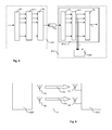
figure 1a shows a phase difference between the DAC and ADC sampling frequencies of, respectively, the transmitter Tx and the receiver Rx. - The period Ts between 2 subsequent samples remains constant and equal at transmitter Tx side and receiver Rx side, but a phase difference ε shits forward the samples at receiver side. This leads to STO (Sample Time Offset), which can be easily compensated.
- The
figure 1b shows the problem caused by SFO (Sample Frequency Offset), mentioned above. This time, the period Ts' between 2 received samples at receiver side is different (here, longer) than the period Ts of the transmitted samples. Therefore, at each sample, the received sample is shifted by an increasing time ε. - After a certain number of samples, a sample will be missed. This would lead to the impossibility to decode the corresponding OFDM symbol.
- Also, after a certain number of samples less than the total number of samples per OFDM symbol, the ADC will fall on a sample of the next OFDM symbol. This situation leads to Inter-Symbol Interference (ISI), which turn leads to the loss of orthogonality of the subcarriers and dramatically decrease of the signal to noise ratio (SNR).
- Similar problems happen when the ADC sampling frequency is greater than the DAC sampling frequency: samples will be repeated instead of being missed, but the consequence remains impossibility to decode some OFDM symbols and a decrease of the signal to noise ratio (SNR).
- This SFO-related problem is partially solved by using pilot signal.
- Pilot-based techniques are employed in the frequency domain, i.e. after the DFT (Discrete Fourier Transform) block of the OFDM receiver chain.
- The SFO is measured by the normalized sampling error given as follows:

- Where T and T' are, respectively, the transmitter and receiver sampling periods. Then, the overall effect after DFT on the received subcarriers Rl,k is as follows:

Where - l is the OFDM symbol index,
- k is the subcarrier index,
- Ts and Tu are the durations of the total OFDM symbol and of the useful data portion, respectively,
- Hl,k is the transfer function associated with the transmission channel between the emitter and the receiver,
- Wl,k is the additive white noise
- And N t
Δ (l,k) is the additional interference due to the sampling frequency offset. The power of this last term can be approximated by:
- Therefore, the degradation grows as the square of the product of the offset tΔ and the subcarrier index k. This means that the outermost subcarriers are most severely impacted. The degradation can also be expressed directly as SNR loss in decibels. The following approximation is derived:

- WLAN OFDM systems typically have relatively small number of subcarriers and quite small offset tΔ. Hence, ktΔ<<1, so that the interference caused by sampling frequency offset can usually be ignored.
- The equation (1) also shows the most significant problem caused by the offset, namely the term

- As discussed above, in WLAN, we only care about correcting the phase error induced by the SFO. This is done by relying on the pilots to estimate their phase difference according to the following:
- The sampling frequency offset (SFO) is estimated by using the knowledge of the linear relationship between the phase rotation caused by the offset and the pilot subcarrier index. The received pilot subcarriers, in a simplified form, are:

Let Zl,k=Rl,kR* l-1,k
This implies:
- According to the above equation, we can see that Zl,k is the multiplication of a pilot of the 1th received OFDM symbol (after the DFT) by the complex conjugate of the same pilot of the previous OFDM symbol.
- Finding the phase of Zl,k is equivalent to finding the phase error caused by the SFO (which is the error that we care about in WLAN, as mentioned before).
- From the above question (3), an estimation t̂Δ of the SFO tΔ can be found by the following equation:

- For better estimation accuracy, since we have more than 1 pilot per OFDM symbol, the above estimation can be applied between the negative and positive pilots of the same received OFDM.

Where:
And
- And where C1 and C2 are the sets of pilots at negative and positive subcarriers respectively. In the case or WLAN 802.11 a/g, C1 = [-21, -7], C2 = [7, 21], mink∈C2=7, and maxk∈C2=21.
- The correction can then be done by different approaches.
- A first approach consists in correcting the clock frequency of the ADC like depicted in
figures 2a and 2b . - The decision block of
figure 2a or the timing error detector block (TED) offigure 2b estimates the SFO tΔ as explained above. - A second approach is illustrated by
figures 3a and 3b , and consists in performing an inverse rotation of the subcarriers after the DFT. This is done by the ROTOR block infigure 3a , which is piloted by the Decision block which estimates the SFO tΔ as explained above. -
Figure 3b shows a non-synchronous sampling system where the sampling rate is fixed and the sampling time offset is compensated by using digital devices such as an FIR interpolating filter. Since it does not require a feedback signal for adjusting the sampling frequency (at ADC), it is simpler to implement then the synchronous sampling systems. However, the nonsynchronous sampling scheme is more vulnerable to SFO if it is not compensated properly. Since a sample can be inserted or lost in one OFDM symbol when SFO is present, the nonsynchronous sampling scheme performs the operations of skip/duplication/interpolation before the FFT operation and compensates for the effect of phase rotation by using FEQ (Frequency-domain Equalizer). - As these approaches are not fully satisfactory, there is a need to improve the situation and to propose a new and alternative approach.
- This is achieved with a method for determining an estimation of a Sampling Frequency Offset of an OFDM signal sent by an emitter to a receiver over a transmission channel, said signal being constituted of symbols; said method comprising:
- sending symbols by said emitter through a first path of said transmission channel;
- sending said symbols by said emitter through a second path of said transmission channel; said second path having a different ratio between the durations of a total OFDM symbol and a useful data portion of it;
- determining said estimation according to received symbols through said first and second paths.
- According to embodiments of the invention, the method may comprise one or several of the following features, taken alone or in partial or full combinations:
- said estimation is determined according to the equation

wherein Rl,k,p1 and Rl,k,p2 corresponds to said received symbols from, respectively said first path and said second path, and wherein Ts and Tu are said durations of a total OFDM symbol and a useful data portion of it, respectively, k represents the subcarrier, and c is a parameter. - said estimation is determined as an average value taken for all the pilot subcarriers k
- said estimation is determined as an average value taken for all the subcarriers
- said duration of a total OFDM symbol is equal to 4µs for said first path and said second path, and said duration of a useful data portion differs between said first path and said second path, so that (Ts/Tu)p1 = c*(Ts/Tu)p2.
- said parameter (c) is transmitted by said emitter (EMT) inside preamble symbols of said OFDM signal.
- Another aspect of the invention relates to a method for receiving an OFDM signal consisting in determining an estimation of a Sampling Frequency Offset as previously described and compensating for said Sampling Frequency Offset of said OFDM signal according to said estimation.
- Another aspect of the invention relates to a computer program comprising program instructions and being loadable into a data processing unit and adapted to cause execution of the method previously described when the computer program is run by the data processing unit.
- Still Another aspect of the invention relates to a receiver adapted for determining an estimation of a Sampling Frequency Offset an OFDM signal received from an emitter over a transmission channel, said signal being constituted of symbols; said receiver comprising means for:
- receiving symbols from said emitter through a first path of said transmission channel;
- receiving said symbols from said emitter through a second path of said transmission channel; said second path having a different ratio between the durations of a total OFDM symbol and a useful data portion of it;
- determining said estimation according to received symbols through said first and second paths.
- According to embodiments of the invention, the method may comprise one or several of the following features, taken alone or in partial or full combinations:
- said means are determining said estimation according to the equation

wherein Rl,k,p1 and Rl,k,p2 corresponds to said received symbols from, respectively said first path and said second path, and wherein Ts and Tu are said durations of a total OFDM symbol and a useful data portion of it, respectively, k represents the subcarrier, and c is a parameter. - said estimation is determined as an average value taken for all the pilot subcarriers k
- said estimation is determined as an average value taken for all the subcarriers
- said duration of a total OFDM symbol is equal to 4µs for said first path and said second path, and said duration of a useful data portion differs between said first path and said second path, so that (Ts/Tu)p1 = c*(Ts/Tu)p2.
- said parameter is received from said emitter inside preamble symbols of said OFDM signal.
- Another aspect of the invention relates to a receiver adapted for determining an estimation of a Sampling Frequency Offset as previously desribed and for compensating for said Sampling Frequency Offset of said OFDM signal according to said estimation.
- Further features and advantages will appear from the following description of some embodiments of the invention, given as non-limiting examples, with reference to the accompanying drawings listed hereunder.
-
-
Fig. 1a and 1b , already commented, depict undesirable effects due to synchronization issues between receiver and transmitter. -
Fig. 2a and 2b , already commented, depict implementation of the SFO compensation by correcting the clock frequency of the ADC. -
Fig. 3a and 3b , already commented, depict implementation of the SFO compensation by performing an inverse rotation of the subcarriers after the DFT. -
Fig. 4 illustrates a simplified and high-level block diagram of an OFDM system according to embodiments of the invention. -
Fig. 5 shows OFDM emitter and an OFDM receiver communicating through two communication paths. -
FIG.1 illustrates a simplified and high-level block diagram of an OFDM system comprising an emitter EMT and a receiver RCV connected by a communication channel TC. This communication channel is usually (but not necessarily) wireless and perturbed by noise. - The principle of this OFDM system consists in transmitting several symbols (or signal) in parallel by assigning to each of them a different carrier, each carrier being orthogonal to the others. The number of carriers (or subcarriers) depends on the total bandwidth and on the duration of a symbol (i.e. the size of the time window in which the receiver can capture the transmitted symbols).
- The symbols to be transmitted, initially in the frequency domain, are transposed into the time domain and modulated for transmission over the communication channel TC. The receiver RCV transposes the received signals back to the frequency domain to extract the transmitted symbols.
- More precisely, the symbols to be transmitted at emitter EMT side are first appropriately encoded and then sent to a serial-to-parallel transformer SPE. This function blocks aims in extracting from a symbol, a number N of individual values Xl[k], where "k" ranges from 1 to N-1 and "1" represents the ordinal number of the OFDM symbol to be transmitted.
- This number N is equal to the number of subcarriers used for the transmission over the communication channel TC. It depends on the standard. For instance according to WLAN 802.11a, 52 subcarriers are used (48 data subcarriers + 4 pilot subcarriers), and 12 (6 on the "left" and 6 on the "right") subcarriers are not used (zero subcarriers). Here and in the following descriptions, the variable k will be used for the frequency domain and the variable n for time domain.
- The symbols Xl[k] which are outputted by the serial-to-parallel transformer SPE are provided to a frequency-to-time conversion module IDFT. This frequency-to-time convertor can perform an inverse discrete Fourier Transform of the symbols to generate symbols xl[n] in the time domain. It is often implemented by an inverse Fast Fourier Transform (I-FFT).
- These symbols are then multiplexed by the parallel-to-serial transformer PSE to produce a signal transmitted over the transmission channel TC.
- The transmission channel is modeled in the frequency domain by its associated transfer function Hl(k). It is modeled in the time domain by its impulse response hl(n). Hl(k) is the Fourier transform of hl(n).
- The transfer function represents the channel multipath behavior, delay, and complex attenuation. The transfer function may vary over time and is therefore indexed by the number of the transmitted symbol.
- The multiplexer PSE modulates the orthogonal subcarriers by the symbols to be transmitted.
- The transmitted OFDM symbol signal spectrum is the sum in the frequency domain of the orthogonal subcarrier sinc functions that are superposed over each other. The individual symbols can be independently modulated by using different types of modulations techniques, like for instance QAM (Quadrature Amplitude Modulation) or PSK (Phase-Shift Keying).
- The symbols are then received by the receiver RCV. The received symbols are functions of the emitted symbols and of the transfer function Hk of the transmission channel, and of noise perturbing this channel.
- The receiver RCV comprises a receiving function module RFM which generates demodulated symbols from the received symbols stream. The demodulated symbols can then be passed over to other circuitry of the receiver RCV (not depicted).
- The receiving function module RFM may perform different steps which are usual in OFDM systems but may be subject to variations and different implementations.
- The high-level schema of the
figure 1 shows a possible implementation where the receiving function module RFM comprises: - a serial-to-parallel transformer or demultiplexer SPR, which parallelizes the received symbol to a set of time symbols.
- A time-to-frequency conversion module DFT. This convertor can perform a discrete Fourier Transform of the time symbols to generate received symbols as a set of received frequency bins in the frequency domain, corresponding to determined subcarriers.
- A parallel-to-serial transformer PSR to produce symbols made of these received frequency bins. These symbols can then be transmitted to other circuitries of the receiver RCV (not depicted in the figure).
- In order to perform these steps, the receiving function module RFM shares with the emitter EMT the same subcarriers frequencies, as well as the number of subcarriers N. They could have been communicated beforehand, or they may be set or tuned previously in both the emitter and receiver, for instance according to standards specifications.
- However, the received symbols may have been perturbed during the transmission over the transmission channel TC. They can be received with potential CFO and STO. No information can be determined by the receiver RCV about the nature of the transmission channel to help valuing the STO. In other words, at the moment of STO estimation, we do not have information about the transfer function of the channel. Therefore, the receiver RCV should rely on blind determination techniques to compensate for the effects of the Symbol Time Offset (STO).
- The present invention is particularly useful in 4th generation and LTE (Long-Term Evolution) OFDM-MIMO systems where spatial multiplexing is employed.
- This technique is based on digital signal processing in the frequency domain, i.e. after the time-to-frequency conversion block, DFT, of the receiver RCV) and after equalization (i.e. after channel estimation and equalization blocks in the Rx chain). The technique has the advantages of being not necessarily pilot-based, applicable at each received subcarriers (i.e. applicable in the tracking phase of SFO estimation), of better estimation precision versus SNR-based approaches and has an easy implementation.
-
FIG. 5 shows a MIMO-OFDM system where spatial multiplexing exists. MIMO stands for Multiple Input-Multiple Outputs and refers to a transmission channel TC between a emitter EMT having several antennas A1, A2 and a receiver RCV having also several antennas A3, A4. Consequently, the transmission channel TC has several paths, p1, p2, between the emitter and the receiver. - This allows increasing the channel capacity thanks to this transmitter diversity.
- According to the invention, the emitter EMT sends the same symbols through a first path p1 and through a second path p2. It can possibly send the same symbols through additional paths also, but the rest of the description will be based on a 2-path embodiment.
- The two paths p1, p2 have different ratios between the duration Ts of a total OFDM symbol and the duration Tu of the useful data portion.
- We can then write (Ts/Tu)p1 = c*(Ts/Tu)p2, where c is a parameter.
- In the case of WLAN OFDM system, compliant with IEEE 802 a/g standards, the duration of a total OFDM symbol is set at 4 µs. Thus, the duration of the useful data portion Tu differs between the first and the second paths, so that (Ts/Tu)p1 = c*(Ts/Tu)p2, wherein:
- (Ts/Tu)p1 is the ratio between the duration Ts of a total OFDM symbol and the duration Tu of the useful data portion for the first path, p1, and
- (Ts/Tu)p2 is the ratio between the duration Ts of a total OFDM symbol and the duration Tu of the useful data portion for the second path p2.
- As shown in the
figure 4 , the receiver RCV has the appropriate means for receiving these symbols through first and second paths, e.g. thanks to the receiving function module RFM. - The receiver RCV has also means, e.g. the computing module CMP, for determining an estimation of the Sampling Frequency Offset (SFO) of the received signals according to these received symbols through first and second paths.
- More precisely, this determination is performed from the received symbols in the frequency domain (thus, after the time-to-frequency conversion block DFT) and after equalization. As it will be demonstrated below, by taking into account the received signal from two different paths (at least), some unknowns can be removed so that it is possible for the receiver RCV to determine an accurate estimation for the SFO: this estimation becomes then a function of the argument (i.e. the phase) of the ratio of the received symbols through a path by the received symbols of the other path. This estimation can be done for a given subcarrier k or averaged along several or all subcarriers of the OFDM signal.
- In other words, after equalizing, through dividing a subcarrier k received via the first path p1 by the same subcarrier k received via the second path p2, the phase of the outcome of the division can be used to estimate the SFO tΔ similarly as the phase of Zl,k in equation (3) is used today to estimate tΔ.
- This is proved through the equations below, which reuse the previously-described equation (2) for the received subcarriers via the first path p1:

- Where Tl,,k is the kth subcarrier of the transmitted
OFDM symbol number 1. Hk,p1 is the transfer function of the first path p1 of the transmission channel at the kth subcarrier frequency. - On the other hand, the received subcarriers via path2 are expressed as:

- Where Tl,k is the kth subcarrier of the transmitted
OFDM symbol number 1 and Hk,p2 is the transfer function of the second path p2 of the transmission channel at the kth subcarrier frequency. - As we explained above, we need to satisfy the following equation:

- And the signal processing is applied after channel estimation and equalization: we note R'l,k,p1 and R'l,k,p2 the received symbols from paths p1 and p2 respectively, after equalization.
- After equalization, Hk,p1 and Hk,p2 are equalized and the received subcarriers of equation A and B become as follows:


- By dividing equation D by equation E, and using equation C, we get:

- This implies that the estimation t̂ Δ for the SFO tΔ is as follows:

- This estimation is performed here for a single subcarrier k. For better estimation accuracy, it is possible to determine this estimation as an average value taken for several subcarriers, e.g. for all the pilot subcarriers.
- For better estimation accuracy, it is also possible to determine the estimation in equation F by taking an average value of all the subcarriers. In this embodiment, we finally get:

N is the total number of subcarriers. N = 52 in the case of WLAN 802.11 a/g. - Averaging the estimates over all the subcarriers has the further advantage of providing much more immunity to noise than averaging the estimates over all the pilot subcarriers. This is because the total number of subcarriers is much greater than the number of pilot subcarriers. This gives our technique superiority in terms of estimation precision versus signal-to-noise ratio (SNR) based approaches.
- This parameter c can be known by the receiver RCV by different ways.
- It can be a hard-coded value, stored inside the emitter and inside the receiver during fabrication or configuration.
- It can also be a value sent by the emitter during the transmission of the preamble symbols of the OFDM signal.
- According to an embodiment of the invention, for each subcarrier k, the arg function in Equation G can be implemented using a cordic that calculates the tan-1 function of the division of the equalized path1 and path2 versions of the same transmitted subcarrier.
- The result at the output of the cordic is then multiplied by

- After the multiplication, the results corresponding to all subcarriers are summed together and divided by N.
- The estimated SFO can then be corrected and compensated according to methods and functional architectures known in the art, e.g. like those explained above.
- This solution presents numerous advantages over prior approaches, including:
- The implementation is easy.
- It has a better spectral efficiency since it is independent of pilot subcarriers.
- When compared to all other SFO estimation techniques, simulation results proved that this technique has a better precision versus SNR.
- The invention has been described with reference to preferred embodiments. However, many variations are possible within the scope of the invention.
Claims (15)
- Method for determining an estimation of a Sampling Frequency Offset of an OFDM signal sent by an emitter (EMT) to a receiver (RCV) over a transmission channel (TC), said signal being constituted of symbols; said method comprising:- sending symbols by said emitter through a first path of said transmission channel;- sending said symbols by said emitter through a second path of said transmission channel; said second path having a different ratio between the durations of a total OFDM symbol and a useful data portion of it;- determining said estimation according to received symbols through said first and second paths.
- Method according to claim 1, wherein said estimation is determined according to the equation

wherein Rl,k,p1 and Rl,k,p2 corresponds to said received symbols from, respectively said first path and said second path, and wherein Ts and Tu are said durations of a total OFDM symbol and a useful data portion of it, respectively, k represents the subcarrier, and c is a parameter. - Method according to claim 1 or 2, wherein said estimation is determined as an average value taken for all the pilot subcarriers k
- Method according to claim 1 or 2, wherein said estimation is determined as an average value taken for all the subcarriers
- Method according to any of the previous claims wherein said duration of a total OFDM symbol is equal to 4µs for said first path and said second path, and said duration of a useful data portion differs between said first path and said second path, so that (Ts/Tu)p1 = c*(Ts/Tu)p2.
- Method according to any of the claims 2 to 5, wherein said parameter (c) is transmitted by said emitter (EMT) inside preamble symbols of said OFDM signal.
- Method for receiving an OFDM signal consisting in determining an estimation of a Sampling Frequency Offset according to any of the previous claims and compensating for said Sampling Frequency Offset of said OFDM signal according to said estimation.
- Computer program comprising program instructions and being loadable into a data processing unit and adapted to cause execution of the method according to any of previous claims when the computer program is run by the data processing unit.
- Receiver (RCV) adapted for determining an estimation of a Sampling Frequency Offset an OFDM signal received from an emitter (EMT) over a transmission channel (TC), said signal being constituted of symbols; said receiver comprising means for:- receiving symbols from said emitter through a first path of said transmission channel;- receiving said symbols from said emitter through a second path of said transmission channel; said second path having a different ratio between the durations of a total OFDM symbol and a useful data portion of it;- determining said estimation according to received symbols through said first and second paths.
- Receiver according to claim 9, wherein said means are determining said estimation according to the equation

wherein Rl,k,p1 and Rl,k,p2 corresponds to said received symbols from, respectively said first path and said second path, and wherein Ts and Tu are said durations of a total OFDM symbol and a useful data portion of it, respectively, k represents the subcarrier, and c is a parameter. - Receiver according to claim 9 or 10, wherein said estimation is determined as an average value taken for all the pilot subcarriers k
- Receiver according to claim 9 or 10, wherein said estimation is determined as an average value taken for all the subcarriers
- Receiver according to any of the claims 9 to 12, wherein said duration of a total OFDM symbol is equal to 4µs for said first path and said second path, and said duration of a useful data portion differs between said first path and said second path, so that (Ts/Tu)p1 = c*(Ts/Tu)p2.
- Receiver according to any of the claims 10 to 13, wherein said parameter (c) is received from said emitter (EMT) inside preamble symbols of said OFDM signal.
- Receiver adapted for determining an estimation of a Sampling Frequency Offset according to any of the claims 9 to 14 and for compensating for said Sampling Frequency Offset of said OFDM signal according to said estimation.
Priority Applications (3)
| Application Number | Priority Date | Filing Date | Title |
|---|---|---|---|
| EP20130305957 EP2704387B1 (en) | 2012-08-27 | 2013-07-05 | SFO estimation technique for MIMO-OFDM frequency synchronization |
| US14/416,661 US9306788B2 (en) | 2012-08-27 | 2013-07-23 | SFO estimation technique for MIMO-OFDM frequency synchronization |
| PCT/EP2013/065487 WO2014032861A1 (en) | 2012-08-27 | 2013-07-23 | Sfo estimation technique for mimo-ofdm frequency synchronization |
Applications Claiming Priority (3)
| Application Number | Priority Date | Filing Date | Title |
|---|---|---|---|
| EP12306024 | 2012-08-27 | ||
| US201261697389P | 2012-09-06 | 2012-09-06 | |
| EP20130305957 EP2704387B1 (en) | 2012-08-27 | 2013-07-05 | SFO estimation technique for MIMO-OFDM frequency synchronization |
Publications (2)
| Publication Number | Publication Date |
|---|---|
| EP2704387A1 true EP2704387A1 (en) | 2014-03-05 |
| EP2704387B1 EP2704387B1 (en) | 2015-04-29 |
Family
ID=46800145
Family Applications (1)
| Application Number | Title | Priority Date | Filing Date |
|---|---|---|---|
| EP20130305957 Not-in-force EP2704387B1 (en) | 2012-08-27 | 2013-07-05 | SFO estimation technique for MIMO-OFDM frequency synchronization |
Country Status (3)
| Country | Link |
|---|---|
| US (1) | US9306788B2 (en) |
| EP (1) | EP2704387B1 (en) |
| WO (1) | WO2014032861A1 (en) |
Cited By (3)
| Publication number | Priority date | Publication date | Assignee | Title |
|---|---|---|---|---|
| CN107317779A (en) * | 2016-04-26 | 2017-11-03 | 中兴通讯股份有限公司 | A kind of frequency deviation estimating method and device |
| CN110933009A (en) * | 2019-11-26 | 2020-03-27 | 紫光展锐(重庆)科技有限公司 | Frequency offset estimation method, system, electronic device and storage medium |
| CN118200086A (en) * | 2024-05-20 | 2024-06-14 | 成都泰格微电子研究所有限责任公司 | An interference identification method based on frequency domain equalization method |
Families Citing this family (2)
| Publication number | Priority date | Publication date | Assignee | Title |
|---|---|---|---|---|
| CN106452531B (en) * | 2016-10-27 | 2019-07-23 | 西安交通大学 | A Multi-User Uplink Frequency Synchronization Method Based on Massive MIMO |
| CN111817841B (en) * | 2020-06-08 | 2023-03-21 | 深圳友讯达科技股份有限公司 | Blind time sequence error detection method, system and storage medium suitable for low signal-to-noise ratio |
Family Cites Families (6)
| Publication number | Priority date | Publication date | Assignee | Title |
|---|---|---|---|---|
| KR100587310B1 (en) * | 2004-08-18 | 2006-06-08 | 엘지전자 주식회사 | Frequency Synchronizer and DW-H Reception System Using the Same |
| US20090190675A1 (en) * | 2004-08-31 | 2009-07-30 | Qualcomm Incorporated | Synchronization in a broadcast ofdm system using time division multiplexed pilots |
| GB2440981A (en) * | 2006-08-18 | 2008-02-20 | Fujitsu Ltd | Wireless multi-hop communication system |
| EP2077634B1 (en) * | 2006-10-26 | 2016-02-24 | Fujitsu Limited | Radio base station apparatus, pilot transmitting method thereof and terminal apparatus |
| US8483235B2 (en) * | 2007-12-11 | 2013-07-09 | Electronics And Telecommunications Research Institute | Apparatus and method for channel estimation in MIMO systems |
| EP2290893A1 (en) * | 2009-08-24 | 2011-03-02 | Nxp B.V. | Frequency Synchronization in OFDM Receiver using sliding Fourier Transform |
-
2013
- 2013-07-05 EP EP20130305957 patent/EP2704387B1/en not_active Not-in-force
- 2013-07-23 WO PCT/EP2013/065487 patent/WO2014032861A1/en not_active Ceased
- 2013-07-23 US US14/416,661 patent/US9306788B2/en not_active Expired - Fee Related
Non-Patent Citations (1)
| Title |
|---|
| JUHA HEISKALA; JOHN TERRY, 1 September 2002, OFDM WIRELESS LANS: A THEORETICAL AND PRACTICAL GUIDE, SAMS PUBLISHING, USA, PAGE(S) 62 - 66, USA, pages: 62 - 66, XP002714997 * |
Cited By (4)
| Publication number | Priority date | Publication date | Assignee | Title |
|---|---|---|---|---|
| CN107317779A (en) * | 2016-04-26 | 2017-11-03 | 中兴通讯股份有限公司 | A kind of frequency deviation estimating method and device |
| CN110933009A (en) * | 2019-11-26 | 2020-03-27 | 紫光展锐(重庆)科技有限公司 | Frequency offset estimation method, system, electronic device and storage medium |
| CN110933009B (en) * | 2019-11-26 | 2022-04-12 | 紫光展锐(重庆)科技有限公司 | Frequency offset estimation method, system, electronic device and storage medium |
| CN118200086A (en) * | 2024-05-20 | 2024-06-14 | 成都泰格微电子研究所有限责任公司 | An interference identification method based on frequency domain equalization method |
Also Published As
| Publication number | Publication date |
|---|---|
| US9306788B2 (en) | 2016-04-05 |
| EP2704387B1 (en) | 2015-04-29 |
| US20150188745A1 (en) | 2015-07-02 |
| WO2014032861A1 (en) | 2014-03-06 |
Similar Documents
| Publication | Publication Date | Title |
|---|---|---|
| JP5497800B2 (en) | Method and apparatus for compensating for carrier frequency offset in orthogonal frequency division multiplexing wireless communication system | |
| US7844006B2 (en) | Method of non-uniform doppler compensation for wideband orthogonal frequency division multiplexed signals | |
| US10237095B2 (en) | Linear equalization for use in low latency high speed communication systems | |
| JP4406398B2 (en) | OFDM signal transmission method and transmitter, and OFDM signal receiver | |
| US9306789B2 (en) | Estimation of CFO based on relative values of frequency bins corresponding to used subcarriers of received preamble symbols for OFDM systems | |
| US9191042B2 (en) | Interference cancellation technique for channel estimation in OFDM receivers | |
| EP2744162B1 (en) | Estimation of the CFO based on channel impulse response for OFDM synchronization | |
| US9413580B2 (en) | Symbol time offset correction via intercarrier interference detection in OFDM receiver | |
| CN102263719B (en) | Frequency offset compensating and balancing method and device for orthogonal frequency division multiplexing system | |
| EP2192735A1 (en) | Receiving apparatus and method for receiving signals in a wireless communication system with improved equalization performance | |
| US10181923B2 (en) | Apparatus and method for generating and using a pilot signal | |
| US10826662B2 (en) | Transmitter and method for formatting transmit data into a frame structure | |
| EP2704387B1 (en) | SFO estimation technique for MIMO-OFDM frequency synchronization | |
| CN104836770B (en) | It is a kind of based on related average and adding window timing estimation method | |
| US11201765B2 (en) | Receiver, transmitter, wireless communication network and method to communicate a non-pulse shaped signal in a multi carrier pulse shaped transmission system | |
| US8050335B2 (en) | Equal phase combining technique for a robust OFDM system | |
| EP2770686A1 (en) | Estimation of the cfo by transmission of a single-subcarrier signal in ofdm system | |
| EP2779504A1 (en) | Adapted bit loading for OFDM system using modulus and phase of estimated transfer function of the communication channel | |
| Trubuil et al. | Synchronization, Doppler and channel estimation for OFDM underwater acoustic communications | |
| JP5645613B2 (en) | Wireless communication system, transmitter and receiver | |
| Zhang et al. | A new channel estimation algorithm for fast linear-time-varying channel in MIMO-OFDM systems | |
| Lee | Doppler effect compensation scheme based on constellation estimation for OFDM system | |
| JP7761132B2 (en) | Wireless communication method, transmitting device, receiving device, and wireless communication system | |
| WO2014041006A1 (en) | A new interpolation algorithm for pilot-based channel estimation in ofdm systems | |
| Arslan | Channel frequency response estimation under the effect of RF impairements in OFDM based wireless systems |
Legal Events
| Date | Code | Title | Description |
|---|---|---|---|
| AK | Designated contracting states |
Kind code of ref document: A1 Designated state(s): AL AT BE BG CH CY CZ DE DK EE ES FI FR GB GR HR HU IE IS IT LI LT LU LV MC MK MT NL NO PL PT RO RS SE SI SK SM TR |
|
| AX | Request for extension of the european patent |
Extension state: BA ME |
|
| PUAI | Public reference made under article 153(3) epc to a published international application that has entered the european phase |
Free format text: ORIGINAL CODE: 0009012 |
|
| 17P | Request for examination filed |
Effective date: 20140305 |
|
| RBV | Designated contracting states (corrected) |
Designated state(s): AL AT BE BG CH CY CZ DE DK EE ES FI FR GB GR HR HU IE IS IT LI LT LU LV MC MK MT NL NO PL PT RO RS SE SI SK SM TR |
|
| 17Q | First examination report despatched |
Effective date: 20141020 |
|
| GRAP | Despatch of communication of intention to grant a patent |
Free format text: ORIGINAL CODE: EPIDOSNIGR1 |
|
| INTG | Intention to grant announced |
Effective date: 20141219 |
|
| GRAS | Grant fee paid |
Free format text: ORIGINAL CODE: EPIDOSNIGR3 |
|
| GRAA | (expected) grant |
Free format text: ORIGINAL CODE: 0009210 |
|
| AK | Designated contracting states |
Kind code of ref document: B1 Designated state(s): AL AT BE BG CH CY CZ DE DK EE ES FI FR GB GR HR HU IE IS IT LI LT LU LV MC MK MT NL NO PL PT RO RS SE SI SK SM TR |
|
| REG | Reference to a national code |
Ref country code: GB Ref legal event code: FG4D |
|
| REG | Reference to a national code |
Ref country code: CH Ref legal event code: EP |
|
| REG | Reference to a national code |
Ref country code: AT Ref legal event code: REF Ref document number: 724973 Country of ref document: AT Kind code of ref document: T Effective date: 20150515 |
|
| REG | Reference to a national code |
Ref country code: IE Ref legal event code: FG4D |
|
| REG | Reference to a national code |
Ref country code: DE Ref legal event code: R096 Ref document number: 602013001622 Country of ref document: DE Effective date: 20150611 |
|
| REG | Reference to a national code |
Ref country code: NL Ref legal event code: VDEP Effective date: 20150429 |
|
| REG | Reference to a national code |
Ref country code: AT Ref legal event code: MK05 Ref document number: 724973 Country of ref document: AT Kind code of ref document: T Effective date: 20150429 |
|
| REG | Reference to a national code |
Ref country code: LT Ref legal event code: MG4D |
|
| PG25 | Lapsed in a contracting state [announced via postgrant information from national office to epo] |
Ref country code: NL Free format text: LAPSE BECAUSE OF FAILURE TO SUBMIT A TRANSLATION OF THE DESCRIPTION OR TO PAY THE FEE WITHIN THE PRESCRIBED TIME-LIMIT Effective date: 20150429 |
|
| PG25 | Lapsed in a contracting state [announced via postgrant information from national office to epo] |
Ref country code: ES Free format text: LAPSE BECAUSE OF FAILURE TO SUBMIT A TRANSLATION OF THE DESCRIPTION OR TO PAY THE FEE WITHIN THE PRESCRIBED TIME-LIMIT Effective date: 20150429 Ref country code: LT Free format text: LAPSE BECAUSE OF FAILURE TO SUBMIT A TRANSLATION OF THE DESCRIPTION OR TO PAY THE FEE WITHIN THE PRESCRIBED TIME-LIMIT Effective date: 20150429 Ref country code: NO Free format text: LAPSE BECAUSE OF FAILURE TO SUBMIT A TRANSLATION OF THE DESCRIPTION OR TO PAY THE FEE WITHIN THE PRESCRIBED TIME-LIMIT Effective date: 20150729 Ref country code: HR Free format text: LAPSE BECAUSE OF FAILURE TO SUBMIT A TRANSLATION OF THE DESCRIPTION OR TO PAY THE FEE WITHIN THE PRESCRIBED TIME-LIMIT Effective date: 20150429 Ref country code: FI Free format text: LAPSE BECAUSE OF FAILURE TO SUBMIT A TRANSLATION OF THE DESCRIPTION OR TO PAY THE FEE WITHIN THE PRESCRIBED TIME-LIMIT Effective date: 20150429 Ref country code: PT Free format text: LAPSE BECAUSE OF FAILURE TO SUBMIT A TRANSLATION OF THE DESCRIPTION OR TO PAY THE FEE WITHIN THE PRESCRIBED TIME-LIMIT Effective date: 20150831 |
|
| PG25 | Lapsed in a contracting state [announced via postgrant information from national office to epo] |
Ref country code: RS Free format text: LAPSE BECAUSE OF FAILURE TO SUBMIT A TRANSLATION OF THE DESCRIPTION OR TO PAY THE FEE WITHIN THE PRESCRIBED TIME-LIMIT Effective date: 20150429 Ref country code: IS Free format text: LAPSE BECAUSE OF FAILURE TO SUBMIT A TRANSLATION OF THE DESCRIPTION OR TO PAY THE FEE WITHIN THE PRESCRIBED TIME-LIMIT Effective date: 20150829 Ref country code: GR Free format text: LAPSE BECAUSE OF FAILURE TO SUBMIT A TRANSLATION OF THE DESCRIPTION OR TO PAY THE FEE WITHIN THE PRESCRIBED TIME-LIMIT Effective date: 20150730 Ref country code: AT Free format text: LAPSE BECAUSE OF FAILURE TO SUBMIT A TRANSLATION OF THE DESCRIPTION OR TO PAY THE FEE WITHIN THE PRESCRIBED TIME-LIMIT Effective date: 20150429 Ref country code: LV Free format text: LAPSE BECAUSE OF FAILURE TO SUBMIT A TRANSLATION OF THE DESCRIPTION OR TO PAY THE FEE WITHIN THE PRESCRIBED TIME-LIMIT Effective date: 20150429 |
|
| PG25 | Lapsed in a contracting state [announced via postgrant information from national office to epo] |
Ref country code: DK Free format text: LAPSE BECAUSE OF FAILURE TO SUBMIT A TRANSLATION OF THE DESCRIPTION OR TO PAY THE FEE WITHIN THE PRESCRIBED TIME-LIMIT Effective date: 20150429 Ref country code: EE Free format text: LAPSE BECAUSE OF FAILURE TO SUBMIT A TRANSLATION OF THE DESCRIPTION OR TO PAY THE FEE WITHIN THE PRESCRIBED TIME-LIMIT Effective date: 20150429 |
|
| REG | Reference to a national code |
Ref country code: DE Ref legal event code: R097 Ref document number: 602013001622 Country of ref document: DE |
|
| PG25 | Lapsed in a contracting state [announced via postgrant information from national office to epo] |
Ref country code: PL Free format text: LAPSE BECAUSE OF FAILURE TO SUBMIT A TRANSLATION OF THE DESCRIPTION OR TO PAY THE FEE WITHIN THE PRESCRIBED TIME-LIMIT Effective date: 20150429 Ref country code: RO Free format text: LAPSE BECAUSE OF NON-PAYMENT OF DUE FEES Effective date: 20150429 Ref country code: MC Free format text: LAPSE BECAUSE OF FAILURE TO SUBMIT A TRANSLATION OF THE DESCRIPTION OR TO PAY THE FEE WITHIN THE PRESCRIBED TIME-LIMIT Effective date: 20150429 Ref country code: SK Free format text: LAPSE BECAUSE OF FAILURE TO SUBMIT A TRANSLATION OF THE DESCRIPTION OR TO PAY THE FEE WITHIN THE PRESCRIBED TIME-LIMIT Effective date: 20150429 Ref country code: CZ Free format text: LAPSE BECAUSE OF FAILURE TO SUBMIT A TRANSLATION OF THE DESCRIPTION OR TO PAY THE FEE WITHIN THE PRESCRIBED TIME-LIMIT Effective date: 20150429 |
|
| PLBE | No opposition filed within time limit |
Free format text: ORIGINAL CODE: 0009261 |
|
| STAA | Information on the status of an ep patent application or granted ep patent |
Free format text: STATUS: NO OPPOSITION FILED WITHIN TIME LIMIT |
|
| PG25 | Lapsed in a contracting state [announced via postgrant information from national office to epo] |
Ref country code: LU Free format text: LAPSE BECAUSE OF FAILURE TO SUBMIT A TRANSLATION OF THE DESCRIPTION OR TO PAY THE FEE WITHIN THE PRESCRIBED TIME-LIMIT Effective date: 20150705 |
|
| 26N | No opposition filed |
Effective date: 20160201 |
|
| REG | Reference to a national code |
Ref country code: IE Ref legal event code: MM4A |
|
| PG25 | Lapsed in a contracting state [announced via postgrant information from national office to epo] |
Ref country code: IT Free format text: LAPSE BECAUSE OF FAILURE TO SUBMIT A TRANSLATION OF THE DESCRIPTION OR TO PAY THE FEE WITHIN THE PRESCRIBED TIME-LIMIT Effective date: 20150429 |
|
| PG25 | Lapsed in a contracting state [announced via postgrant information from national office to epo] |
Ref country code: SI Free format text: LAPSE BECAUSE OF FAILURE TO SUBMIT A TRANSLATION OF THE DESCRIPTION OR TO PAY THE FEE WITHIN THE PRESCRIBED TIME-LIMIT Effective date: 20150429 |
|
| REG | Reference to a national code |
Ref country code: FR Ref legal event code: PLFP Year of fee payment: 4 |
|
| PG25 | Lapsed in a contracting state [announced via postgrant information from national office to epo] |
Ref country code: IE Free format text: LAPSE BECAUSE OF NON-PAYMENT OF DUE FEES Effective date: 20150705 |
|
| PG25 | Lapsed in a contracting state [announced via postgrant information from national office to epo] |
Ref country code: BE Free format text: LAPSE BECAUSE OF FAILURE TO SUBMIT A TRANSLATION OF THE DESCRIPTION OR TO PAY THE FEE WITHIN THE PRESCRIBED TIME-LIMIT Effective date: 20150429 |
|
| REG | Reference to a national code |
Representative=s name: GRUENECKER PATENT- UND RECHTSANWAELTE PARTG MB, DE Ref country code: DE Ref legal event code: R082 Ref document number: 602013001622 Country of ref document: DE |
|
| REG | Reference to a national code |
Ref country code: DE Ref legal event code: R081 Ref document number: 602013001622 Country of ref document: DE Owner name: OCT CIRCUIT TECHNOLOGIES INTERNATIONAL LTD., IE Free format text: FORMER OWNER: ST-ERICSSON SA, PLAN-LES-OUATES, CH |
|
| REG | Reference to a national code |
Ref country code: CH Ref legal event code: PL |
|
| PG25 | Lapsed in a contracting state [announced via postgrant information from national office to epo] |
Ref country code: MT Free format text: LAPSE BECAUSE OF FAILURE TO SUBMIT A TRANSLATION OF THE DESCRIPTION OR TO PAY THE FEE WITHIN THE PRESCRIBED TIME-LIMIT Effective date: 20150429 |
|
| PG25 | Lapsed in a contracting state [announced via postgrant information from national office to epo] |
Ref country code: CH Free format text: LAPSE BECAUSE OF NON-PAYMENT OF DUE FEES Effective date: 20160731 Ref country code: LI Free format text: LAPSE BECAUSE OF NON-PAYMENT OF DUE FEES Effective date: 20160731 |
|
| PG25 | Lapsed in a contracting state [announced via postgrant information from national office to epo] |
Ref country code: BG Free format text: LAPSE BECAUSE OF FAILURE TO SUBMIT A TRANSLATION OF THE DESCRIPTION OR TO PAY THE FEE WITHIN THE PRESCRIBED TIME-LIMIT Effective date: 20150429 Ref country code: HU Free format text: LAPSE BECAUSE OF FAILURE TO SUBMIT A TRANSLATION OF THE DESCRIPTION OR TO PAY THE FEE WITHIN THE PRESCRIBED TIME-LIMIT; INVALID AB INITIO Effective date: 20130705 |
|
| REG | Reference to a national code |
Ref country code: FR Ref legal event code: PLFP Year of fee payment: 5 |
|
| PG25 | Lapsed in a contracting state [announced via postgrant information from national office to epo] |
Ref country code: SE Free format text: LAPSE BECAUSE OF FAILURE TO SUBMIT A TRANSLATION OF THE DESCRIPTION OR TO PAY THE FEE WITHIN THE PRESCRIBED TIME-LIMIT Effective date: 20150429 Ref country code: CY Free format text: LAPSE BECAUSE OF FAILURE TO SUBMIT A TRANSLATION OF THE DESCRIPTION OR TO PAY THE FEE WITHIN THE PRESCRIBED TIME-LIMIT Effective date: 20150429 |
|
| PGFP | Annual fee paid to national office [announced via postgrant information from national office to epo] |
Ref country code: GB Payment date: 20170620 Year of fee payment: 5 Ref country code: FR Payment date: 20170621 Year of fee payment: 5 |
|
| PGFP | Annual fee paid to national office [announced via postgrant information from national office to epo] |
Ref country code: DE Payment date: 20170620 Year of fee payment: 5 |
|
| REG | Reference to a national code |
Ref country code: FR Ref legal event code: TP Owner name: OCT CIRCUIT TECHNOLOGIES INTERNATIONAL LIMITED, IE Effective date: 20180116 |
|
| PG25 | Lapsed in a contracting state [announced via postgrant information from national office to epo] |
Ref country code: SM Free format text: LAPSE BECAUSE OF FAILURE TO SUBMIT A TRANSLATION OF THE DESCRIPTION OR TO PAY THE FEE WITHIN THE PRESCRIBED TIME-LIMIT Effective date: 20150429 |
|
| PG25 | Lapsed in a contracting state [announced via postgrant information from national office to epo] |
Ref country code: MK Free format text: LAPSE BECAUSE OF FAILURE TO SUBMIT A TRANSLATION OF THE DESCRIPTION OR TO PAY THE FEE WITHIN THE PRESCRIBED TIME-LIMIT Effective date: 20150429 Ref country code: TR Free format text: LAPSE BECAUSE OF FAILURE TO SUBMIT A TRANSLATION OF THE DESCRIPTION OR TO PAY THE FEE WITHIN THE PRESCRIBED TIME-LIMIT Effective date: 20150429 |
|
| PG25 | Lapsed in a contracting state [announced via postgrant information from national office to epo] |
Ref country code: AL Free format text: LAPSE BECAUSE OF FAILURE TO SUBMIT A TRANSLATION OF THE DESCRIPTION OR TO PAY THE FEE WITHIN THE PRESCRIBED TIME-LIMIT Effective date: 20150429 |
|
| REG | Reference to a national code |
Ref country code: DE Ref legal event code: R119 Ref document number: 602013001622 Country of ref document: DE |
|
| GBPC | Gb: european patent ceased through non-payment of renewal fee |
Effective date: 20180705 |
|
| PG25 | Lapsed in a contracting state [announced via postgrant information from national office to epo] |
Ref country code: FR Free format text: LAPSE BECAUSE OF NON-PAYMENT OF DUE FEES Effective date: 20180731 Ref country code: GB Free format text: LAPSE BECAUSE OF NON-PAYMENT OF DUE FEES Effective date: 20180705 Ref country code: DE Free format text: LAPSE BECAUSE OF NON-PAYMENT OF DUE FEES Effective date: 20190201 |