EP2704384A2 - Method for decoding a spatially multiplexed data signal using a maximum likelihood detection - Google Patents
Method for decoding a spatially multiplexed data signal using a maximum likelihood detection Download PDFInfo
- Publication number
- EP2704384A2 EP2704384A2 EP13181007.9A EP13181007A EP2704384A2 EP 2704384 A2 EP2704384 A2 EP 2704384A2 EP 13181007 A EP13181007 A EP 13181007A EP 2704384 A2 EP2704384 A2 EP 2704384A2
- Authority
- EP
- European Patent Office
- Prior art keywords
- layer
- constellation
- layers
- data
- symbol
- Prior art date
- Legal status (The legal status is an assumption and is not a legal conclusion. Google has not performed a legal analysis and makes no representation as to the accuracy of the status listed.)
- Granted
Links
- 238000000034 method Methods 0.000 title claims abstract description 91
- 238000007476 Maximum Likelihood Methods 0.000 title claims abstract description 38
- 238000001514 detection method Methods 0.000 title claims abstract description 32
- 239000011159 matrix material Substances 0.000 claims abstract description 66
- 230000001419 dependent effect Effects 0.000 claims abstract description 31
- 238000004891 communication Methods 0.000 claims abstract description 13
- 238000012545 processing Methods 0.000 claims description 29
- 239000013598 vector Substances 0.000 claims description 28
- 238000004590 computer program Methods 0.000 claims description 9
- 239000010410 layer Substances 0.000 description 281
- 238000007792 addition Methods 0.000 description 21
- 230000014509 gene expression Effects 0.000 description 21
- 230000002452 interceptive effect Effects 0.000 description 13
- 230000005540 biological transmission Effects 0.000 description 9
- 239000002356 single layer Substances 0.000 description 9
- 230000008569 process Effects 0.000 description 6
- 230000009467 reduction Effects 0.000 description 6
- 238000000354 decomposition reaction Methods 0.000 description 5
- 238000012360 testing method Methods 0.000 description 5
- 230000008901 benefit Effects 0.000 description 4
- 230000006870 function Effects 0.000 description 3
- 230000002087 whitening effect Effects 0.000 description 3
- 230000000116 mitigating effect Effects 0.000 description 2
- 230000009466 transformation Effects 0.000 description 2
- 238000012935 Averaging Methods 0.000 description 1
- 230000006978 adaptation Effects 0.000 description 1
- 239000000654 additive Substances 0.000 description 1
- 230000000996 additive effect Effects 0.000 description 1
- 238000013459 approach Methods 0.000 description 1
- 230000003190 augmentative effect Effects 0.000 description 1
- 230000008859 change Effects 0.000 description 1
- 230000000295 complement effect Effects 0.000 description 1
- 230000004048 modification Effects 0.000 description 1
- 238000012986 modification Methods 0.000 description 1
- 238000010606 normalization Methods 0.000 description 1
- 238000007670 refining Methods 0.000 description 1
- 230000011218 segmentation Effects 0.000 description 1
- 238000000926 separation method Methods 0.000 description 1
- 230000008054 signal transmission Effects 0.000 description 1
- 230000003595 spectral effect Effects 0.000 description 1
- 230000001131 transforming effect Effects 0.000 description 1
Images

Classifications
-
- H—ELECTRICITY
- H04—ELECTRIC COMMUNICATION TECHNIQUE
- H04L—TRANSMISSION OF DIGITAL INFORMATION, e.g. TELEGRAPHIC COMMUNICATION
- H04L25/00—Baseband systems
- H04L25/02—Details ; arrangements for supplying electrical power along data transmission lines
- H04L25/06—DC level restoring means; Bias distortion correction ; Decision circuits providing symbol by symbol detection
- H04L25/067—DC level restoring means; Bias distortion correction ; Decision circuits providing symbol by symbol detection providing soft decisions, i.e. decisions together with an estimate of reliability
-
- H—ELECTRICITY
- H04—ELECTRIC COMMUNICATION TECHNIQUE
- H04L—TRANSMISSION OF DIGITAL INFORMATION, e.g. TELEGRAPHIC COMMUNICATION
- H04L1/00—Arrangements for detecting or preventing errors in the information received
- H04L1/004—Arrangements for detecting or preventing errors in the information received by using forward error control
- H04L1/0045—Arrangements at the receiver end
- H04L1/0047—Decoding adapted to other signal detection operation
- H04L1/0048—Decoding adapted to other signal detection operation in conjunction with detection of multiuser or interfering signals, e.g. iteration between CDMA or MIMO detector and FEC decoder
-
- H—ELECTRICITY
- H04—ELECTRIC COMMUNICATION TECHNIQUE
- H04L—TRANSMISSION OF DIGITAL INFORMATION, e.g. TELEGRAPHIC COMMUNICATION
- H04L1/00—Arrangements for detecting or preventing errors in the information received
- H04L1/004—Arrangements for detecting or preventing errors in the information received by using forward error control
- H04L1/0045—Arrangements at the receiver end
- H04L1/0047—Decoding adapted to other signal detection operation
- H04L1/005—Iterative decoding, including iteration between signal detection and decoding operation
-
- H—ELECTRICITY
- H04—ELECTRIC COMMUNICATION TECHNIQUE
- H04L—TRANSMISSION OF DIGITAL INFORMATION, e.g. TELEGRAPHIC COMMUNICATION
- H04L1/00—Arrangements for detecting or preventing errors in the information received
- H04L1/02—Arrangements for detecting or preventing errors in the information received by diversity reception
- H04L1/06—Arrangements for detecting or preventing errors in the information received by diversity reception using space diversity
- H04L1/0618—Space-time coding
- H04L1/0631—Receiver arrangements
-
- H—ELECTRICITY
- H04—ELECTRIC COMMUNICATION TECHNIQUE
- H04L—TRANSMISSION OF DIGITAL INFORMATION, e.g. TELEGRAPHIC COMMUNICATION
- H04L25/00—Baseband systems
- H04L25/02—Details ; arrangements for supplying electrical power along data transmission lines
- H04L25/03—Shaping networks in transmitter or receiver, e.g. adaptive shaping networks
- H04L25/03891—Spatial equalizers
-
- H—ELECTRICITY
- H04—ELECTRIC COMMUNICATION TECHNIQUE
- H04L—TRANSMISSION OF DIGITAL INFORMATION, e.g. TELEGRAPHIC COMMUNICATION
- H04L25/00—Baseband systems
- H04L25/02—Details ; arrangements for supplying electrical power along data transmission lines
- H04L25/03—Shaping networks in transmitter or receiver, e.g. adaptive shaping networks
- H04L25/03006—Arrangements for removing intersymbol interference
- H04L2025/0335—Arrangements for removing intersymbol interference characterised by the type of transmission
- H04L2025/03426—Arrangements for removing intersymbol interference characterised by the type of transmission transmission using multiple-input and multiple-output channels
Definitions
- the field of the invention is that of wireless digital communications.
- the invention relates to the transmission and reception, and especially in a MIMO ("Multiple Input Multiple Output”) type or MISO ("Multiple Input Single Output”) type multiple-antenna system, through the transmission of signals subjected to an encoding using a spatial multiplexing.
- MIMO Multiple Input Multiple Output
- MISO Multiple Input Single Output
- these techniques make it possible to attain an increased transmission capacity by augmenting the spectral efficiency in the transmission channel through the use of space/time codes.
- space/time codes can be used especially to distribute the modulated symbols on the different degrees of freedom of the channel.
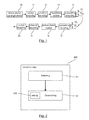
- Figure 1 provides a more precise illustration of a transmission scheme in a multi-antenna system.
- a binary source signal 10 to be sent undergoes a source encoding 11 and then a channel encoding 12. It then goes through a modulation module 13 designed to convert binary elements into complex symbols: such a module thus associates a complex signal, belonging to a constellation (of the QAM type for example), with a group of bits. Then, a space/time encoding 14 of each group of K symbols is performed and these symbols are then sent on n t sending antennas 15 1 to 15n t in a MIMO type transmission context.
- the signal is then conveyed through a transmission channel and then received on the n r receiving antennas 16 1 to 16n r .
- Each receiving antenna receives a linear combination of the symbols sent on each of the n t sending antennas. This linear combination corresponds to a segmentation of the sent signal in multiple layers (in other words: streams, or beams).
- the received signal can be thus represented by a linear transformation plus an additive noise vector B.
- Each layer carries one symbol x i that is selected from the constellation used during the modulation.
- a received layer i is a channel vector H i times the symbol x i .
- the received vector Y comprising N layers is:
- the channel vector H i is known (via special pilots and channel estimation) but the symbol x i is unknown.
- the received signal Y is first of all decoded in a space/time decoding module 17 applying a processing operation corresponding to a reverse of the space/time encoding applied when sending.
- the layer separation is then achieved by an equalizer or detector (not represented) of the decoding block 17.
- the equalizer Given the received vector Y the equalizer aims at finding the symbol x i of each layer i, from the transmitter's constellation of symbols, that minimizes the distance between the two vectors
- the minimum distance is weighted by the inverse noise covariance matrix C -1 .
- the equalized signal at output of the space/time decoding block 17 is then fed into a demodulation module 18 and undergoes operations of channel decoding 19 and source decoding 20, delivering an estimated binary signal.
- the multiple layers are usually orthogonal at the transmitter side where they are linearly combined. But at the receiver side, if the channel conditions are non-ideal, they can arrive as non-orthogonal vectors (after transformation by the channel matrix applied to each vector). Interference between the layers arises in this case.
- the receiver tries to separate the layers in order to simplify the subsequent processing of each layer or subgroup of layers.
- Zero-Forcing (ZF) or the Minimum Mean Squared Error (MMSE) equalizers have been proposed.
- the Zero-Forcing equalizer decodes a layer of interest while ignoring all other interfering layers (as if a unique layer were transmitted), an "interfering layer" being a layer which contains lots of interference.
- the Minimum Mean Squared Error equalizer decodes a layer of interest while assuming that all other interfering layers have Gaussian distribution and behave like noise.
- a first drawback of such methods is the complexity that is involved when considering a small number of layers. Indeed, all the symbols of each constellation of each layer have to be processed for finding the best candidate symbol. In addition, such methods are not really suitable for a hardware implementation.
- the invention proposes a novel solution which does not have all these drawbacks of the prior art, in the form of a method for decoding a received signal Y corresponding to a data signal transmitted in a MIMO communication system through a channel represented by a channel matrix H, said data signal comprising a set of data symbols x transmitted in at least one layer, each layer carrying at least one data symbol belonging to a signal constellation.
- the method comprises, for one of said at least one layer, called a current layer n, a detection step that determines the maximum likelihood for at least one data symbol of said data signal.
- said detection step comprises:
- the invention relies on a novel and inventive approach for decoding a received signal Y corresponding to a data signal transmitted in a MIMO communication system through a channel represented by a channel matrix H using a method for performing a new maximum likelihood detection implementation.
- Such a method permits indeed to achieve a very low complexity maximum likelihood detection (MLD) in MIMO communications, with precise Max-Log-MAP LLR output, without norm approximation and without QR decomposition.
- MLD maximum likelihood detection
- the method according to the invention consists indeed of reducing the complexity by processing at least one layer with fewer and simpler operations than the ones required by the techniques of the prior art.
- one first aspect of reducing the complexity is achieved by the step of selecting, in other words slicing, one candidate value for the data symbol x n of the current layer.
- Such a step permits to avoid the test of all the possible values of the constellation of a layer n since only one value is tested among all the values of the possible values of the constellation.
- the invention uses, in the step of determining, a predetermined constant depending on the size of the constellation of a considered layer, called a constellation dependent constant.
- the invention sets out to counter the prejudices of the man skilled in the art by adding an operation of addition, which succeeds in reducing the whole complexity of the method according to the invention.
- such a predetermined constellation dependent constant helps to increase the speed of said method considering that it is implemented thanks to a binary writing as explained in the following.
- such a predetermined constellation dependent constant can be viewed as a "virtual term”. Adding and subtracting such "virtual terms”, based on constellation type, helps as explained in the following to eliminate multiplications or transform them into one, two or few additions, which is simpler in terms of complexity.
- the method according to the invention is able to take into account noise without using noise pre-whitening, and especially a colored noise, since the expression of the Euclidian distance involve a noise covariance matrix which can be easily adapt as a function of the noise involved in a the considered channel.
- the vector H i H ⁇ C - 1 involving the channel and noise covariance matrix is typically a slow varying term as a function of frequency and time that does not involve the data path (vector Y).
- this vector H i H ⁇ C - 1 can be interpolated over frequency and time, rather than computing the term for each subcarrier.
- the method for decoding according to the invention can be applied independently for any considered layer.
- said constellation dependent constant is equal to (1 + max( x ) 2 )/2, where max ( x ) corresponds to the maximum real part of the candidate values of said constellation of the layer k.
- the constellation of the considered layer is a 64QAM
- such a constellation can be represented advantageously by a normalized representation, which comprises 8 2 points.
- the coordinates of each point is a couple of two integer values, each belonging for example to ⁇ -7, -5, -3, -1, +1, +3, +5, +7 ⁇ .
- the constellation comprises 2 points each belonging to ⁇ -1, +1 ⁇ thus the constellation dependent constant is equal to 1.
- the constellation dependent constant is 1 for QPSK, 1 or 5 for 16QAM, 25 for 64QAM, 113 for 256QAM, 481 for 1024QAM, etc.
- the terms depending on ⁇ k are computed by adding the constant 2.M. ⁇ k to each of them, where M is an integer.
- the method comprises, for all constellation symbols x i and x j different from the constellation symbol x n of the current layer n, an exhaustive search using a maximum likelihood technique for setting values of the constellation symbols x i and x j .
- the data signal comprises symbols transmitted over a plurality of layers.
- the step of determining according to the invention delivers the optimized values of the constellations symbols of all the other layers i and j, and called the layers of interest, which are different from the layer n for which a candidate value has been selected before.
- the current layer n is thus used to optimize the other layers i, j and is not a layer of interest.
- the minimum Euclidian distance is taken over all possible constellation values x i and x j .
- the layer i is of the type 64 QAM, there are 64 possible constellation values.
- the method comprises, for constellation symbols x i of at least one layer i different from the current layer n, a search in a predetermined region of the constellation symbols x i .
- Such an embodiment brings the advantage of reducing the complexity since the search space of a given layer i is reduced.
- Such a reduced subset can be obtained for example by using a minimum mean squared error technique.
- said current layer n is the layer with the highest constellation order.
- choosing a current layer n with the highest constellation order permits to increase the reduction of the processing operations.
- one candidate value for the data symbol x n of the current layer is selected and then used in the step of determining.
- Choosing a current layer n with the highest constellation order in other words the highest size of constellation permits to avoid the test of all the possible values of the highest constellation of a layer n since only one value is tested among all the values of the possible values of the constellation.
- the data signal comprises symbols transmitted over a single layer and determining the Euclidian distance is useful and necessary when considering a subsequent refinement processing.
- the data signal comprises symbols transmitted over two layers.
- said method comprises a subsequent step of decoding, for example a turbo-decoding.
- the noise covariance matrix C is equal to ⁇ 2 I , where I is the identity matrix and ⁇ z is the variance of said white Gaussian noise.
- said step of selecting one candidate value for the data symbol of the current layer n implements a hard-symbol slicing.
- said method implements a soft-bit decision step.
- Such a soft-bit decision helps to improve the accuracy of the step of maximum likelihood detection.
- the method comprises S ⁇ N iterations, each iteration processing Q ⁇ N layers, while the other (N-Q) layers are included in said covariance matrix C, and delivering transmitted symbols of R ⁇ (Q - 1) layers of said Q first layers, called resulting layers, one iteration processing Q layers being different from the resulting layers issued by the previous iterations, Q, R, S being integers able to be different from one iteration to the other.
- each iteration processing two layers while the other (N-2) layers are included in said covariance matrix C and delivering transmitted symbols of one layer of said two first layers, called a resulting layer, one iteration processing two layers being different from the resulting layers issued by the previous iterations.
- Such embodiment permits to obtain the whole N optimized values by processing the layers two layers by two layers in N iterations according to the above example (or in groups of Q layers according to the general principle of this embodiment).
- Such a process permits to reduce the complexity since as seen above processing a data signal comprising symbols transmitted over two layers involves les complex operations than processing a data signal comprising symbols transmitted over N layers.
- the invention pertains to a decoder for decoding a received signal Y corresponding to a data signal transmitted in a MIMO communication system through a channel represented by a channel matrix H, said data signal comprising a set of data symbols x transmitted in at least one layer, each layer carrying at least one data symbol belonging to a signal constellation, said decoder comprises, for one of said at least one layer, called a current layer n, means for detecting that determines the maximum likelihood for at least one data symbol of said data signal, wherein said means for detecting comprises:
- a decoder of this kind is especially adapted to implement the decoding method described here above.
- the invention pertains also to a computer program product downloadable from a communications network and/or stored on a computer readable support and/or executable by a microprocessor, said computer program product comprising program code instructions for implementing a method for decoding a received signal Y corresponding to a data signal transmitted in a MIMO communication system through a channel represented by a channel matrix H, said data signal comprising a set of data symbols x transmitted in at least one layer, each layer carrying at least one data symbol belonging to a signal constellation, wherein said computer program product comprises program code instructions for processing for one of said at least one layer, called a current layer n, a detection step that determines the maximum likelihood for at least one data symbol of said data signal, wherein said detection step comprises:
- the general principal of the invention relies on the combination of two aspects applied on at least one layer of the data signal to be decoded.
- the first aspect is based on a selecting step, which selects one candidate value for a data symbol of a current layer.
- the second aspect is based on the use of predetermined constant depending on the size of the constellation of a considered layer, called a constellation dependent constant in a step of determining distance in a particular expression of the Euclidian distance between the received signal Y and said candidate value multiplied by said channel matrix H, weighted by the inverse of a noise covariance matrix C.
- the data signal comprises at least one layer.
- the method according to the invention comprises, for one of said at least one layer, called a current layer n, a detection step (20).
- Such a detection step (20) comprises two substeps:
- the general solution is to find each symbol x i per layer from the transmitter's constellation of symbols per layer, that minimizes the weighted distance between the two vectors ⁇ Y - ⁇ i H i ⁇ x i ⁇ C - 1 2 .
- the purpose of the detection step according to the invention is to find the hypothetical transmitted candidate that is the nearest to the received vector while taking into account the noise that is added during the reception.
- the step of selecting (21) aims at finding one candidate value for the symbol x n of the layer n.
- the way of implementing such a step of selecting is described with more details in the sections below regarding a first example of the present invention.
- Such a step avoids the test of all the possible values of the constellation of a layer n since only one value is tested among all the values of the possible values of the constellation, which results in reducing the complexity of the maximum likelihood processing.
- the candidate value x n which has been previously selected by the substep of selecting (21), is used to obtain the x k of each other layer k different from the layer n when considering that the data signal comprises data symbol transmitted over a plurality of layers.
- x 4 is set thanks to the step of selecting, and then x 4 is used to find the optimized symbol values x 0 , x 1 , x 2 , x 3 among each constellation of each layer respectively.
- layer 0, layer 1, layer 2 and layer 3 are the layers of interest whereas layer 4 is the current layer, which is fixed to help determining the symbols of the other layers.
- the minimum Euclidian distance is taken over all possible constellation values x i and x j .
- the layer i is of the type 64 QAM, there are 64 possible constellation values.
- the step of determining the Euclidian distance is used as an input for a refinement step implemented for example according to a turbo-decoding.
- the substep of determining (22) an Euclidian distance is performed by using a particular expression of the Euclidian distance and by adding (220) to each of them a predetermined constant depending on the size of the constellation of the layer k, called a constellation dependent constant.
- a soft-bit decision step is performed to get the probabilities of the bit values of x 0 , x 1 , x 2 , x 3 , the same substeps are repeated considering one of the layers among layer 0, layer 1, layer 2 and layer 3 as the current layer for which the candidate value will be selected to get the probabilities of the bit values of x 4 .
- layer 2 is considered as the current layer.
- the value of x 2 is set thanks to the step of selecting and then used to find the probabilities of the bit values values x 0 , x 1 , x 3 , and especially x 4 a step of soft-bit decision is performed delivering in particular the probabilities of the bit values of x 4 .
- a first embodiment is described considering that the data signal comprises data symbol transmitted over a single layer.
- a second embodiment considers that the data signal comprises data symbol transmitted over two layers.
- a third embodiment considers that the data signal comprises data symbol transmitted over N>2 layers, and that these N layers are processed two layers by two layers or more in a plurality S of iterations. According to this embodiment, in each iteration, it is "approximately' considered that the data signal comprises data symbols transmitted in two or more layers instead of N layers, the other layers being integrated in the noise covariance matrix.
- the data signal comprises data symbol x transmitted over a single layer.
- simplifications can be made since there is no interfering layer.
- Symbol x R x + j I x is a constellation symbol carrying P bits mapped to the real or imaginary axis.
- the noise covariance matrix is C and is for example equal to ⁇ 2 I.
- L b be the Log Likelihood Ratio (LLR) of bit b in symbol x.
- LLR Max-Log-MAP Log Likelihood Ratio
- variable x is independent of variable x , which permits minimizing the real part separately (and vice versa).
- a focus is made on the variable x but the same can be inferred directly and unambiguously for variable x .
- the real part can be expressed as: 1 ⁇ 2 ⁇ ⁇ H ⁇ 2 ⁇ R x 2 - 2 R H H ⁇ Y R x ⁇ ⁇ ⁇ R x 2 - 2 ⁇ ⁇ R x with ⁇ ⁇ 1 ⁇ 2 ⁇ ⁇ H ⁇ 2 , ⁇ ⁇ R 1 ⁇ 2 ⁇ H H ⁇ Y , it is possible to determine the best x and corresponding minimum norm by implementing simple shifts registers, which implement some operations of multiplication or division by powers of two, additions and comparisons, assuming x ⁇ ⁇ 1, ⁇ 3, ⁇ 5, ⁇ 7... ⁇ , ( x ) 2 ⁇ ⁇ 1,9,25,49,... ⁇ . This assumption requires pre-normalization, for example of H, by the constellation's Root Mean Square (RMS).
- RMS Root Mean Square
- the step of selecting consists in finding the ⁇ x that is nearest to ⁇ , or equivalently finding the decision region containing ⁇ , where the decision regions are bounded by ⁇ ..., - 6 ⁇ , - 4 ⁇ , - 2 ⁇ , 0,2 ⁇ , 4 ⁇ , 6 ⁇ , ... ⁇ .
- the step of determining (22) the Euclidian distance between the received signal Y and the data signal transmitted using said candidate value multiplied by said channel matrix H, weighted by the inverse of a noise covariance matrix C according to the invention is performed by using the following expression: 2 ⁇ ⁇ R x .
- the terms depending on ⁇ are computed by adding (220) to each of them a predetermined constant depending on the size of the constellation of the layer k, called a constellation dependent constant.
- a constellation dependent constant it is proposed to "virtually” add or subtract constant terms from both minima to further reduce the norm's complexity.
- 2 could be alternatively subtracted to obtain the set ⁇ (( x ) 2 - 5) ⁇ ⁇ -4 ⁇ , 4 ⁇ ⁇ .
- a rule can be applied, which consists in subtracting a "virtual" number, called a constellation dependent constant, to reduce the total number of bits in the binary representation of the resulting set of norms (hence minimizing number of additions), and in considering that negative numbers can be obtained from positive numbers with a simple negation operation.
- the invention proposes to maintain some symmetry between positive and negative numbers in order to reduce the dynamic range of the norms (for fixed pointing considerations).
- An optimized constellation dependent constant to subtract in this case is the mid-range (1 + max( x ) 2 )/2, which makes the positive and negative dynamic ranges equal. For instance, this number is 1 for QPSK, 5 for 16QAM, 25 for 64QAM, 113 for 256QAM, 481 for 1024QAM, etc.
- an enhancement can be achieved by subtracting the constant term 2 H H Y ⁇ 2 ⁇ then 2 ⁇ ( x + 1) ⁇ ⁇ 0, ⁇ 4 ⁇ , ⁇ 8 ⁇ , ⁇ 12 ⁇ , 16 ⁇ ) and consists of one addition, two negations and plain shifts.
- the sets 2 ⁇ ( x + 1) ⁇ (0, 4 ⁇ ⁇ and 2 ⁇ ( x + 1) ⁇ ⁇ 0, ⁇ 4 ⁇ , 8 ⁇ ⁇ are obtained.
- scaling by 1/ ⁇ 2 can be either applied to the output Log Likelihood Ratio (LLR), or embedded in the two primary dot products, H H ⁇ Y ⁇ 2 and ⁇ H ⁇ 2 ⁇ 2 (e.g. by scaling H H ⁇ 2 ).
- LLR Log Likelihood Ratio
- H H ⁇ Y ⁇ 2 and ⁇ H ⁇ 2 ⁇ 2 e.g. by scaling H H ⁇ 2 .
- the step of determining (22) according to the invention delivers a Euclidian distance for a data signal that comprises data symbols transmitted over a single layer. Such a Euclidian distance is then used for an enhancement step using for instance turbo-decoding.
- a soft-decision is obtained for some bits (bit interleaved coded modulation) by subtracting the distances of two previous hard-decisions using a hard-symbol slicing as described above (where the two hard-decisions are obtained from two distinct constellations, e.g. one constellation for the bit equal to 0, and the other constellation for the bit equal to 1).
- a subset of allowed symbols is obtained. For each subset, selecting the nearest symbol is implemented using a hard-symbol slicer. For instance, for Gray coded 64QAM, there are three bits per dimension with values 0 or 1, hence six subsets. Each subset is given by a row in table 1xx -7 -5 -3 -1 . . . . 0xx . . . . +1 +3 +5 +7 x1x -7 -5 . . . . +5 +7 x0x . . -3 -1 +3 . . xx1 -7 . . -1 +1 . . +7 xx0 .
- a fast solution for slicing all six subsets at once is to use the result from the hard-symbol slicer described above; the index of the hard-symbol is equal to the index of the "winning" column in table. For example, if the symbol selected thanks to the hard-symbol slicer has a real part equal to -5, the "winning" column is the second column with an index equal to two.
- LLR Max-Log-MAP Log Likelihood Ratio
- noise pre-whitening has higher complexity and power consumption since it requires a Cholesky decomposition and it is applied to the data path.
- C -1 H can be (approximately) interpolated to adjacent symbols or subcarriers, similarly to H, which can dramatically reduce complexity of this product. This is illustrated in 3.
- the interpolation trick cannot be used by the Cholesky decomposition C -1/2 applied to the data path, C -1/2 Y, since Y is a fast varying signal.
- MMSE Minimum Mean Square Error
- MMSE Minimum Mean Square Error
- SNR signal to noise ratio
- R YY C + ⁇ l ⁇ H l H l H , , i.e. it contains all layers plus noise (received signal covariance matrix whose statistical average is E YY H ).
- MMSE Minimum Mean Square Error
- inverting 2x2 matrix R YY - 1 requires inverting the determinant of R YY - 1 .
- This division operation can be merged with 1 1 - ⁇ i to produce a unique division per layer i. This saves one division compared to the traditional method of post-weighting by signal to noise ratios i (SNR i ) (total of 2 divisions instead of 3).
- L 0 b be the Log Likelihood Ratio (LLR) of bit b in symbol x 0 .
- L 1 b be the Log Likelihood Ratio (LLR) of bit b in symbol x 1 .
- the first layer 0 is considered to be the layer of interest, in other terms the layer for which it is desired to obtain the optimized value of the symbol x 0 .
- the second layer 1 can be obtained by reversing the roles of first and second layers. In some cases, the second layer is an unwanted interferer and there is no need to compute L 1b .
- LLR Max-Log-MAP Log Likelihood Ratio
- C -1 is omitted from the dot products but it is implicitly assumed that all dot products and norms are weighted by C -1 , in particular the five primary dot products ⁇ H 0 ⁇ C - 1 2 , ⁇ H 1 ⁇ C - 1 2 , H 0 H ⁇ C - 1 ⁇ Y , H 1 H ⁇ C - 1 ⁇ Y , H 1 H ⁇ C - 1 ⁇ H 0 .
- the substep of selecting consists in choosing a candidate value for the layer 1 by using for example a hard-symbol slicer.
- such a substep of selecting delivers the symbol x 1 that is used subsequently in the substep of determining an Euclidian distance to determine the optimized symbol x 0 .
- x 1 comes from constellation of layer 1, which can have different constellation order than constellation of layer 0.
- the constellation of layer 1 is 64QAM
- the constellation of layer 0 is QPSK.
- Such a selection reduces the number of operations since it avoids the test of all the possible values of the constellation of the layer 1 since only one value is tested among all the values of the possible values of the constellation.
- 2 is expressed as the sum of the two norms ⁇ H 0 ⁇ 2 ⁇ x 0 ⁇ k 2 - 2 R H 0 H ⁇ Y ⁇ x 0 ⁇ k * + ⁇ H 1 ⁇ 2 ⁇ x 1 2 - 2 R H 1 H ⁇ Y k ⁇ x 1 * , where the constant term
- 2 has been ignored (indeed it vanishes after subtraction of the two minima), and where Y k Y - H 0 x 0 k .
- R x 0 ⁇ k , R x 1 (and intermediate x 0 k ) are regrouped as following for the real part : ⁇ H 0 ⁇ 2 ⁇ R x 0 ⁇ k 2 - 25 - 2 ⁇ R H 0 H ⁇ Y + R H 1 H ⁇ H 0 + I H 1 H ⁇ H 0 ⁇ R x 0 ⁇ k + 1 + ⁇ H 1 ⁇ 2 ⁇ R x 1 2 - 25 - 2 ⁇ R H 1 H ⁇ Y - R H 1 H ⁇ H 0 ⁇ x 0 ⁇ k ⁇ R x 1 + 1 ⁇ ⁇ 0 ⁇ R 0 ⁇ k 2 - 25 - 2 ⁇ ⁇ 0 R ⁇ R x 0 ⁇ k + 1 +
- the constellation dependent constant is respectively equal to 1 or 5.
- the norm ⁇ 0 (( x 0 k ) 2 - 25) - 2 ⁇ 0 ( x 0 k + 1) can be pre-computed with a few additions and then summed up for each combination of R x 0 ⁇ k , I x 0 ⁇ k via 64 additions.
- the constellation dependent constant 25 of ⁇ 0 (( x 0 k ) 2 - 25) - 2 ⁇ 0 ( x 0 k + 1) is obtained considering the constellation order of layer 0 as being 64QAM but would be different considering another constellation (QPSK, 16QAM, etc.) as already explained above.
- norm ⁇ H 1 ⁇ 2 ⁇ I x 1 2 - 25 for R x 1 and I x 1 can be summed and pre-stored for all combinations of R x 1 2 and I x 1 2 .
- norm ⁇ 1 (( x 1 ) 2 - 25) - 2 ⁇ 1 ( x 1 + 1) can be obtained via maximum four additions, or an average two and a half additions (including adding up the norms for R x 1 and I x 1 , and norm
- the real variable in this term can be merged into ⁇ H 0 ⁇ 2 ⁇ R x 0 2 - 2 R H 0 H ⁇ Y R x 0 while the imaginary variable is merged into the equivalent norm for I x 0 (not shown in our formulas).
- a term for the imaginary formula is obtained in a similar way (not shown here) to be merged into ⁇ H 0 ⁇ 2 ⁇ R x 0 2 - 2 R H 0 H ⁇ Y R x 0 .
- a soft-bit decision step is performed to get the probabilities of the bit values of the symbol of each layer.
- the substeps of the method according to the invention including a step of soft-bit decision are first implemented considering that the current layer is layer 0, which delivers the probabilities of the bit values of x 0 , and then repeated considering that the current layer is layer 1, which delivers the probabilities of the bit values of x 1 .
- the "roles" of the layer 0 and of the layer 1 are reversed.
- Such an embodiment is a variant to process a signal comprising data symbols transmitted in more than two layers and is illustrated by figure 4 .
- the method comprises S ⁇ N iterations, each iteration processing Q ⁇ N layers, while the other (N-Q) layers are included in said covariance matrix C, and delivering transmitted symbols of R ⁇ ( Q - 1) layers of said Q first layers, called resulting layers, one iteration processing Q layers being different from the resulting layers issued by the previous iterations, Q, R, S being integers able to be different from one iteration to the other.
- Such embodiment permits to obtain the whole N optimized values by processing the layers two layers by two layers in N iterations.
- Such a process permits to reduce the complexity of an iteration since as seen above processing a data signal comprising symbols transmitted over two layers involves les complex operations than processing a data signal comprising symbols transmitted over N layers.
- Such embodiment is particularly adapted when some of the transmitted layers have a QAM (quadrature amplitude modulation) constellation distribution and some have Gaussian distribution, and permits to use an hybrid detector using both maximum likelihood detection (MLD) and Minimum Mean Square Error (MMSE).
- QAM quadrature amplitude modulation
- This detector consists in finding the nearest points in a multi-dimensional constellation with the distances weighted by colored Gaussian noise.
- This detector can be implemented as maximum likelihood detection (MLD) for the non-Gaussian layers while using a colored noise covariance matrix that includes the remaining Gaussian layers. I.e. Minimum Mean Square Error (MMSE) equalization of Gaussian layers is incorporated in the noise covariance matrix.
- MMD maximum likelihood detection
- MMSE Minimum Mean Square Error
- MLD maximum likelihood detection
- MMSE Minimum Mean Square Error
- Minimum Mean Square Error (MMSE) equalizer implicitly isolates one layer of interest and treats all remaining layers as colored Gaussian noise.
- Minimum Mean Square Error (MMSE) equalizer can thus be viewed as implementing the method described in the first embodiment for a data signal comprising data symbols transmitted in a single layer with the remaining layers included in the noise covariance. The operation is repeated for each layer of interest.
- MMSE Minimum Mean Square Error
- MLD maximum likelihood detection
- MMSE Minimum Mean Square Error
- the multiple layers are split into two groups: two layers are selectively picked for the maximum likelihood detection according to the second embodiment, and the additional layers are processed as colored interference with known covariance matrix (Minimum Mean Square Error (MMSE) group).
- MMSE Minimum Mean Square Error
- the Minimum Mean Square Error (MMSE) group is essentially treated similarly to linear Minimum Mean Square Error (MMSE) equalization, and it implicitly assumes Gaussian distribution of the symbol carried by each layer.
- the first selected layer, H i x i is the layer to decode, i.e. the layer of interest.
- the second selected layer, H j x j is, for example, the layer that interferes most with the first layer (constellation order can also be part of the selection criteria: selecting an interfering layer with a low constellation order improves maximum likelihood detection (MLD) robustness, since Max-Log-MAP maximum likelihood detection (MLD) relies on selecting a candidate value for the interfering layer; a third criteria for the selection can be based on predicting the equalizer's output SNR per selection). The second layer will not be decoded at this point.
- This colored covariance matrix implicitly assumes Minimum Mean Square Error equalization (MMSE) of the remaining layers given a layer of interest.
- MMSE Minimum Mean Square Error equalization
- a larger number Q of layers (3, 4, etc.) can be selected and processed thanks to the method according to the invention, which uses a maximum likelihood detection and treat all remaining layers with Minimum Mean Square Error as if they were Gaussian distributed.
- Q can be different from one iteration to the other.
- a pre-stage using a Minimum Mean Square Error (MMSE) equalizer is used to select a subset (61) of candidate values for x 0 the symbol of the layer 0 of interest.
- MMSE Minimum Mean Square Error
- the subset of candidate values for x 0 is obtained using a hard-symbol slicer as described above, but instead of outputting one single hard-symbol, several nearest symbols are outputted; for example five nearest real symbols R x 0 ⁇ k and five nearest imaginary symbols I x 0 ⁇ k for a total of 25 symbols x 0 k (instead of 64 symbols for 64QAM) as shown in figure 6 .
- MLD maximum likelihood detection
- the solution can be viewed as a concatenation of Minimum Mean Square Error (MMSE) equalizer followed by maximum likelihood detection (MLD) according to the invention on a reduced set as illustrated by figure 5 .
- MMSE Minimum Mean Square Error
- MLD maximum likelihood detection
- the pre-stage of slicing x 0 essentially focuses on layer 0 while assuming other layers such as layer 1 as Gaussian distributed (Gaussian noise). It acts like Minimum Mean Square Error slicing but instead of limiting the number of outputs to a unique hard-symbol, it finds a square (or rectangular or circular%) region around the initial Zero Forcing candidate as illustrated by figure 6 .
- the square region (61) is extended to other lattice dimensions for the other layers, and the overall search region has the shape of a hyper-parallelepiped (or hyper-cylinder).
- MMSE Minimum Mean Square Error
- the steps of the method according to the invention are performed considering a current layer 1 for example, with a size of possible values x 0 k to parse, which is now 25 instead of 64, for example.
- a solution can be to use the Log Likelihood Ratio (LLR) that can be obtained from the pre-stage of MMSE (or to set the corresponding the Log Likelihood Ratio (LLR) to infinity).
- LLR Log Likelihood Ratio
- An encoding device as illustrated in figure 7 , comprises a memory 71 comprising a buffer memory, a processing unit 72 equipped for example with a microprocessor ⁇ P and driven by the computer program 73, implementing the method for decoding according to the invention.
- the code instructions of the computer program 73 are for example loaded into a RAM and then executed by the processor of the processing unit 72.
- the processing unit 72 receives a current data signal to be decoded.
- the microprocessor of the processing unit 62 implements the steps of the method for decoding described here above according to the computer program instructions 63 to encode the current image.
- the decoder comprises, in addition to the buffer memory 61, means for means for detecting that determines the maximum likelihood for at least one data symbol of said data signal. Said means for detecting comprises:
Landscapes
- Engineering & Computer Science (AREA)
- Computer Networks & Wireless Communication (AREA)
- Signal Processing (AREA)
- Power Engineering (AREA)
- Radio Transmission System (AREA)
- Error Detection And Correction (AREA)
Abstract
- selecting (21) one candidate value for the data symbol of the layer,
- determining (22) the Euclidian distance between the received signal Y and the data signal transmitted using said candidate value multiplied by said channel matrix H, weighted by the inverse of a noise covariance matrix C such as


Description
- The field of the invention is that of wireless digital communications.
- More specifically, the invention relates to the transmission and reception, and especially in a MIMO ("Multiple Input Multiple Output") type or MISO ("Multiple Input Single Output") type multiple-antenna system, through the transmission of signals subjected to an encoding using a spatial multiplexing.
- The techniques of transmission in systems comprising multiple antennas have many advantages.
- In particular, these techniques make it possible to attain an increased transmission capacity by augmenting the spectral efficiency in the transmission channel through the use of space/time codes. These space/time codes can be used especially to distribute the modulated symbols on the different degrees of freedom of the channel.
-
Figure 1 provides a more precise illustration of a transmission scheme in a multi-antenna system. - On the sending side, a
binary source signal 10 to be sent undergoes asource encoding 11 and then a channel encoding 12. It then goes through amodulation module 13 designed to convert binary elements into complex symbols: such a module thus associates a complex signal, belonging to a constellation (of the QAM type for example), with a group of bits. Then, a space/time encoding 14 of each group of K symbols is performed and these symbols are then sent on nt sending antennas 151 to 15nt in a MIMO type transmission context. - The signal is then conveyed through a transmission channel and then received on the nr receiving antennas 161 to 16nr. Each receiving antenna receives a linear combination of the symbols sent on each of the nt sending antennas. This linear combination corresponds to a segmentation of the sent signal in multiple layers (in other words: streams, or beams).
- The received signal can be thus represented by a linear transformation plus an additive noise vector B. Each layer carries one symbol xi that is selected from the constellation used during the modulation.
- Considering that a received layer i is a channel vector Hi times the symbol xi . The received vector Y, comprising N layers is:
- Y = H0 x 0 + H1 x 1 + ··· + B, where Y, B and the Hi for i ∈ [0, N - 1] are vectors of size n r ×1 where nr is the number of receiving antennas. The covariance matrix of the noise B is denoted by matrix C.
- At the receiver, the channel vector Hi is known (via special pilots and channel estimation) but the symbol xi is unknown.
- Thus, the received signal Y is first of all decoded in a space/
time decoding module 17 applying a processing operation corresponding to a reverse of the space/time encoding applied when sending. - The layer separation is then achieved by an equalizer or detector (not represented) of the
decoding block 17. Given the received vector Y the equalizer aims at finding the symbol xi of each layer i, from the transmitter's constellation of symbols, that minimizes the distance between the two vectors ||Y - Hx||2 i.e. the hypothetical transmitted candidate (without noise) that is the nearest to the received vector. When the noise is taken into account, the minimum distance is weighted by the inverse noise covariance matrix C-1. - The equalized signal at output of the space/
time decoding block 17 is then fed into ademodulation module 18 and undergoes operations ofchannel decoding 19 andsource decoding 20, delivering an estimated binary signal. - Unfortunately, owing to the use of several antennas, the decoding of the received signals is particularly complex.
- Indeed, the multiple layers are usually orthogonal at the transmitter side where they are linearly combined. But at the receiver side, if the channel conditions are non-ideal, they can arrive as non-orthogonal vectors (after transformation by the channel matrix applied to each vector). Interference between the layers arises in this case.
- Using known methods for equalizing, the receiver tries to separate the layers in order to simplify the subsequent processing of each layer or subgroup of layers.
- However, the complexity of these known methods for equalizing greatly increases depending on the number of antennas and the number of modulation states.
- Some solutions have been proposed to reduce especially the cost of complexity of the equalizer. Among these solutions the Zero-Forcing (ZF) or the Minimum Mean Squared Error (MMSE) equalizers have been proposed.
- The Zero-Forcing equalizer decodes a layer of interest while ignoring all other interfering layers (as if a unique layer were transmitted), an "interfering layer" being a layer which contains lots of interference. The Minimum Mean Squared Error equalizer decodes a layer of interest while assuming that all other interfering layers have Gaussian distribution and behave like noise.
- These two techniques, respectively ignoring all other interfering layers or assuming that all other interfering layers have Gaussian distribution, do not correspond to the reality and are thus less efficient in terms of performance.
- Thus, in order to obtain high decoding performance, it is necessary to use an optimal decoding technique, in terms of maximum likelihood decoding in the
decoding module 17. - Indeed Maximum Likelihood Detector (MLD) method for equalizing takes into account the true distribution of each interfering layer, i.e. its constellation. Thus, using such a method leads to an increase in decoding performance but at the cost of an increase of complexity since all the possible values of the constellation of each layer are tested. As a consequence, when using a maximum likelihood detector, the overall number of possible values to test grows exponentially with the number of layers.
- Indeed, state of the art solutions implementing a Maximum Likelihood Detector (MLD) method for equalizing correspond for example to the known sphere decoding, Lenstra-Lenstra-Lovász (LLL) reduction, or a decomposition transforming the channel matrix into a triangular matrix with plenty of zeros called the QR decomposition, methods.
- However, such state of the art solutions implementing a Maximum Likelihood Detector (MLD) method for equalizing presents some known drawbacks.
- A first drawback of such methods is the complexity that is involved when considering a small number of layers. Indeed, all the symbols of each constellation of each layer have to be processed for finding the best candidate symbol. In addition, such methods are not really suitable for a hardware implementation.
- In addition, such methods does not propose efficient solutions for dealing with interference mitigation (where noise is colored, e.g. unknown interfering layers, and for example represented by a colored noise covariance matrix is C = EBB H (nr ×nr ) with E the expectation operator, i.e. averaging over all possible realizations. Indeed, in such methods a noise pre-whitening is performed, which involves an additional step and as a consequence an increase of the complexity of the process.
- The invention proposes a novel solution which does not have all these drawbacks of the prior art, in the form of a method for decoding a received signal Y corresponding to a data signal transmitted in a MIMO communication system through a channel represented by a channel matrix H, said data signal comprising a set of data symbols x transmitted in at least one layer, each layer carrying at least one data symbol belonging to a signal constellation.
- According to the invention, the method comprises, for one of said at least one layer, called a current layer n, a detection step that determines the maximum likelihood for at least one data symbol of said data signal.
- In addition, according to the invention, said detection step comprises:
- selecting one candidate value for the data symbol of the current layer n,
- determining the Euclidian distance between the received signal Y and the data signal transmitted using candidate value
- H k is a vector representing the channel associated to a layer k, with k E {i, j, n}, i, j, n ∈ [0, N - 1], i, j, n being integers, possibly equal and N being the number of layers of said data signal;
- xk is the constellation symbol of the layer k;




and where the terms depending on αk are computed by adding (220) to each of them a predetermined constant depending on the size of the constellation of the layer k, called a constellation dependent constant. - Thus the invention relies on a novel and inventive approach for decoding a received signal Y corresponding to a data signal transmitted in a MIMO communication system through a channel represented by a channel matrix H using a method for performing a new maximum likelihood detection implementation.
- Such a method permits indeed to achieve a very low complexity maximum likelihood detection (MLD) in MIMO communications, with precise Max-Log-MAP LLR output, without norm approximation and without QR decomposition.
- The method according to the invention consists indeed of reducing the complexity by processing at least one layer with fewer and simpler operations than the ones required by the techniques of the prior art.
- According to the invention, one first aspect of reducing the complexity is achieved by the step of selecting, in other words slicing, one candidate value for the data symbol xn of the current layer. Such a step permits to avoid the test of all the possible values of the constellation of a layer n since only one value is tested among all the values of the possible values of the constellation.
- According to a second aspect of reducing the complexity, the invention uses, in the step of determining, a predetermined constant depending on the size of the constellation of a considered layer, called a constellation dependent constant.
- By combining these two aspects, the invention sets out to counter the prejudices of the man skilled in the art by adding an operation of addition, which succeeds in reducing the whole complexity of the method according to the invention.
- Indeed, such a predetermined constellation dependent constant helps to increase the speed of said method considering that it is implemented thanks to a binary writing as explained in the following. In addition, such a predetermined constellation dependent constant can be viewed as a "virtual term". Adding and subtracting such "virtual terms", based on constellation type, helps as explained in the following to eliminate multiplications or transform them into one, two or few additions, which is simpler in terms of complexity.
- Implementing such an addition is not obvious since it requires first to determine a particular expression of the Euclidian distance between the received signal and the data signal transmitted using the candidate value.
- In addition, it can be seen that the method according to the invention is able to take into account noise without using noise pre-whitening, and especially a colored noise, since the expression of the Euclidian distance involve a noise covariance matrix which can be easily adapt as a function of the noise involved in a the considered channel.
- Such a way of handling noise presents also the advantage of being simple to implement. In particular, the vector


- The method for decoding according to the invention can be applied independently for any considered layer.
- According to one particular aspect of the invention, said constellation dependent constant is equal to (1 + max(x)2)/2, where max(
 x) corresponds to the maximum real part of the candidate values of said constellation of the layer k.
- For example, if the constellation of the considered layer is a 64QAM, such a constellation can be represented advantageously by a normalized representation, which comprises 82 points. The coordinates of each point is a couple of two integer values, each belonging for example to {-7, -5, -3, -1, +1, +3, +5, +7}.
- Thus, adding a constellation dependent constant equal to 25= (1+(7)2)/2 to terms depending on αk results in that αk ((x)2 - 25) ∈ {0, -16αk , ±24αk } which is really easier to process in terms of binary writing in a program.

- According to the expression (1 + max(Rx)2)/2, it appears clearly that the value of the constellation dependent constant varies with the size of the considered constellation.
- Indeed, for QPSK for example, the constellation comprises 2 points each belonging to {-1, +1} thus the constellation dependent constant is equal to 1.
- Considering a similarly normalized constellation representation, the constellation dependent constant is 1 for QPSK, 1 or 5 for 16QAM, 25 for 64QAM, 113 for 256QAM, 481 for 1024QAM, etc.
- According to one other particular characteristic of the invention, the terms depending on βk are computed by adding the constant 2.M.βk to each of them, where M is an integer. In particular, M=+/-1 can be considered as the best case.
- Such an addition that also goes counter the prejudices of the man skilled in the art; helps to improve again the reduction of complexity of maximum likelihood detection (MLD) in MIMO communications.
- According to an embodiment of the invention, the method comprises, for all constellation symbols xi and xj different from the constellation symbol xn of the current layer n, an exhaustive search using a maximum likelihood technique for setting values of the constellation symbols xi and xj .
- According to this embodiment, it is considered that the data signal comprises symbols transmitted over a plurality of layers. After an exhaustive search, the step of determining according to the invention delivers the optimized values of the constellations symbols of all the other layers i and j, and called the layers of interest, which are different from the layer n for which a candidate value has been selected before.
- In other terms, the current layer n is thus used to optimize the other layers i, j and is not a layer of interest.
- Indeed, the minimum Euclidian distance is taken over all possible constellation values xi and xj . For example, if the layer i is of the type 64 QAM, there are 64 possible constellation values.
- According to another embodiment, the method comprises, for constellation symbols xi of at least one layer i different from the current layer n, a search in a predetermined region of the constellation symbols xi .
- Such an embodiment brings the advantage of reducing the complexity since the search space of a given layer i is reduced. Such a reduced subset can be obtained for example by using a minimum mean squared error technique.
- According to another particular characteristic, said current layer n is the layer with the highest constellation order.
- Thus, considering different sizes of constellation layers, choosing a current layer n with the highest constellation order, in other words the highest size of constellation, permits to increase the reduction of the processing operations.
- Indeed in the step of selecting, one candidate value for the data symbol xn of the current layer is selected and then used in the step of determining. Choosing a current layer n with the highest constellation order, in other words the highest size of constellation permits to avoid the test of all the possible values of the highest constellation of a layer n since only one value is tested among all the values of the possible values of the constellation.
- According to one embodiment of the invention, said signal comprises a set of data symbols transmitted in one layer, i=j=n=0 and

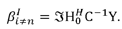
- According to such embodiment, the data signal comprises symbols transmitted over a single layer and determining the Euclidian distance is useful and necessary when considering a subsequent refinement processing.
- As already said, such a method permits to reduce the complexity even if the data signal comprises only one later since it involves very few and simple operations.
- According to another embodiment, said signal comprises a set of data symbols transmitted in two layers, i=j, et,


- According to this embodiment, it is considered that the data signal comprises symbols transmitted over two layers. After an exhaustive search, the step of determining according to the invention delivers the optimized values of the constellations symbols of the layers i for example i=0, called the layer of interest, which is different from the layer n, for example n=1, for which a candidate value has been selected before.
- In other terms, the current layer n=1 is thus used to optimize the other layers i=0, and is not a layer of interest.
- Indeed, the minimum Euclidian distance is taken over all possible constellation values x0
- According to a particular characteristic of this embodiment, when the terms depending on βk are computed by adding the constant 2.M.βk to each of them, where M is an integer and considering that


- Such aspect results in increasing the reduction of the complexity of the method for a data signal comprising symbols transmitted over two layers, since the new expressions of


- Advantageously, said method comprises a subsequent step of decoding, for example a turbo-decoding.
- It can be said that all steps of the method of decoding described above correspond to a first decoding step. After this first decoding step, an additional step of decoding can be implemented for refining. For example such a refinement is implemented by using a turbo-decoding.
- According to another particular aspect of the invention, when the noise is white Gaussian noise, the noise covariance matrix C is equal to σ 2 I, where I is the identity matrix and σz is the variance of said white Gaussian noise.
- According to another particular aspect of the invention, said step of selecting one candidate value for the data symbol of the current layer n implements a hard-symbol slicing.
- According to another particular aspect of the invention, said method implements a soft-bit decision step.
- Such a soft-bit decision helps to improve the accuracy of the step of maximum likelihood detection.
- According to an embodiment, wherein when said signal comprises a set of data symbols transmitted in N>2 layers, the method comprises S≤N iterations, each iteration processing Q<N layers, while the other (N-Q) layers are included in said covariance matrix C, and delivering transmitted symbols of R≤ (Q - 1) layers of said Q first layers, called resulting layers, one iteration processing Q layers being different from the resulting layers issued by the previous iterations, Q, R, S being integers able to be different from one iteration to the other.
- In particular, according to an example of such embodiment where Q=2" each iteration processing two layers while the other (N-2) layers are included in said covariance matrix C, and delivering transmitted symbols of one layer of said two first layers, called a resulting layer, one iteration processing two layers being different from the resulting layers issued by the previous iterations.
- Such embodiment permits to obtain the whole N optimized values by processing the layers two layers by two layers in N iterations according to the above example (or in groups of Q layers according to the general principle of this embodiment). Such a process permits to reduce the complexity since as seen above processing a data signal comprising symbols transmitted over two layers involves les complex operations than processing a data signal comprising symbols transmitted over N layers.
- In addition, according to this example, at each iteration the other layers, different from the two processed layers of the iteration are taken into account since they are treated as noise.
- In another embodiment, the invention pertains to a decoder for decoding a received signal Y corresponding to a data signal transmitted in a MIMO communication system through a channel represented by a channel matrix H, said data signal comprising a set of data symbols x transmitted in at least one layer, each layer carrying at least one data symbol belonging to a signal constellation,
said decoder comprises, for one of said at least one layer, called a current layer n, means for detecting that determines the maximum likelihood for at least one data symbol of said data signal,
wherein said means for detecting comprises: - means for selecting one candidate value for the data symbol of the current layer n,
- means for determining the Euclidian distance between the received signal Y and the data signal transmitted using said candidate value
- H k is a vector representing the channel associated to a layer k, with k E {i, j, n}, i, j, n ∈ [0, N - 1], i, j, n being integers, possibly equal and N being the number of layers of said data signal;
- xk is the constellation symbol of the layer k;




- A decoder of this kind is especially adapted to implement the decoding method described here above.
- The invention pertains also to a computer program product downloadable from a communications network and/or stored on a computer readable support and/or executable by a microprocessor, said computer program product comprising program code instructions for implementing a method for decoding a received signal Y corresponding to a data signal transmitted in a MIMO communication system through a channel represented by a channel matrix H, said data signal comprising a set of data symbols x transmitted in at least one layer, each layer carrying at least one data symbol belonging to a signal constellation,
wherein said computer program product comprises program code instructions for processing for one of said at least one layer, called a current layer n, a detection step that determines the maximum likelihood for at least one data symbol of said data signal,
wherein said detection step comprises: - selecting one candidate value for the data symbol of the current layer n,
- determining the Euclidian distance between the received signal Y and said candidate value multiplied by said channel matrix H, weighted by the inverse of a noise covariance matrix C such as


wherein:- H k is a vector representing the channel associated to a layer k, with k E {i, j, n}, i, j, n ∈ [0, N - 1], i, j, n being integers, possibly equal and N being the number of layers of said data signal;
- xk is the constellation symbol of the layer k;


wherein the terms depending on αk are computed by adding to each of them a predetermined constant depending on the size of the constellation of the layer k, called a constellation dependent constant.
- Other features and advantages of embodiments of the invention shall appear from the following description of a particular embodiment, given by way of an illustrative and non-exhaustive example and from the appended drawings, of which:
-
Figure 1 already commented upon with reference to the prior art presents a transmission scheme of a MIMO system; -
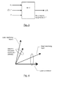
Figure 2 illustrates the main steps of the decoding method according to the invention; -
Figures 3 and 4 illustrate two different examples of embodiments of the invention; -
Figures 5 and 6 illustrate an optional substep of the invention; -
Figure 7 presents the structure of a decoding device applying the decoding method of the invention. - The general principal of the invention relies on the combination of two aspects applied on at least one layer of the data signal to be decoded. The first aspect is based on a selecting step, which selects one candidate value for a data symbol of a current layer. And the second aspect is based on the use of predetermined constant depending on the size of the constellation of a considered layer, called a constellation dependent constant in a step of determining distance in a particular expression of the Euclidian distance between the received signal Y and said candidate value multiplied by said channel matrix H, weighted by the inverse of a noise covariance matrix C.
- These two aspects taken in combination leads to an efficient reduction of the complexity of the method of decoding in comparison with classical method of decoding based on a maximum likelihood technique detection. Indeed, all the classical complex computations are replaced by a few primary dot products of channel and data vectors.
- In addition, colored noise is automatically and cheaply handled by replacing the primary dot products with inverse noise covariance weighted dot products, of the type H H C-1Y and

- Referring to
figure 2 , we now present the mains steps of the method for decoding according to one general embodiment of the invention, considering that the data signal comprises at least one layer. - According to this embodiment, considering that the data signal comprises data symbol transmitted in at least one layer, the method according to the invention comprises, for one of said at least one layer, called a current layer n, a detection step (20).
- Such a detection step (20) comprises two substeps:
- selecting (21) one candidate value for the data symbol of the current layer n,
- determining (22) the Euclidian distance between the received signal Y and the data signal transmitted using said candidate value multiplied by said channel matrix H, weighted by the inverse of a noise covariance matrix C such as


- Indeed, for any type of equalizer implemented in a decoder, given an observation vector Y, the general solution is to find each symbol xi per layer from the transmitter's constellation of symbols per layer, that minimizes the weighted distance between the two vectors


- In this way, the step of selecting (21) aims at finding one candidate value for the symbol xn of the layer n. The way of implementing such a step of selecting is described with more details in the sections below regarding a first example of the present invention.
- As already said such a step permits to fix one value for the symbol xn among the whole possible values of the constellation of the layer n.
- Thus, such a step avoids the test of all the possible values of the constellation of a layer n since only one value is tested among all the values of the possible values of the constellation, which results in reducing the complexity of the maximum likelihood processing.
- In the second substep of the invention, the step of determining (22) the Euclidian distance between the received signal Y and the data signal transmitted using said candidate value xn.
- The candidate value xn, which has been previously selected by the substep of selecting (21), is used to obtain the xk of each other layer k different from the layer n when considering that the data signal comprises data symbol transmitted over a plurality of layers.
- In this way, considering a data signal containing for example five layers called
layer 0,layer 1, layer 2, layer 3, and layer 4, the value of x4 is set thanks to the step of selecting, and then x4 is used to find the optimized symbol values x0, x1, x2, x3 among each constellation of each layer respectively. Here, it is said thatlayer 0,layer 1, layer 2 and layer 3 are the layers of interest whereas layer 4 is the current layer, which is fixed to help determining the symbols of the other layers. - Indeed, the minimum Euclidian distance is taken over all possible constellation values xi and xj . For example, if the layer i is of the type 64 QAM, there are 64 possible constellation values.
- Considering the special case in which the data signal comprises data symbol transmitted over a single layer, the step of determining the Euclidian distance is used as an input for a refinement step implemented for example according to a turbo-decoding.
- As can be seen, the substep of determining (22) an Euclidian distance is performed by using a particular expression of the Euclidian distance and by adding (220) to each of them a predetermined constant depending on the size of the constellation of the layer k, called a constellation dependent constant.
- As already mentioned above, such a predetermined constellation dependent constant can be viewed as a "virtual term". Adding and subtracting such "virtual terms", based on constellation type, helps as explained in the following to eliminate multiplications or transform them into one, two or few additions, which is simpler in terms of complexity.
- Then and optionally, a soft-bit decision step is performed to get the probabilities of the bit values of x0, x1, x2, x3, the same substeps are repeated considering one of the layers among
layer 0,layer 1, layer 2 and layer 3 as the current layer for which the candidate value will be selected to get the probabilities of the bit values of x4. - For example, layer 2 is considered as the current layer. The value of x2 is set thanks to the step of selecting and then used to find the probabilities of the bit values values x0, x1, x3, and especially x4 a step of soft-bit decision is performed delivering in particular the probabilities of the bit values of x4.
- Thus, after for example two iterations of the substeps of the invention including a step of soft-bit decision, all the probabilities of the bit values of x0, x1, x2, x3 and x4 are obtained.
- It is important to note that independently from the number of layers involved in the transmissions, for each layer the substeps described above are implemented.
- Different ways of implementing such substeps are now described considering several different embodiments.
- In this embodiment the general expression given above is simplified as a function of the number of the considered layers of the data signal.
- A first embodiment is described considering that the data signal comprises data symbol transmitted over a single layer.
- A second embodiment considers that the data signal comprises data symbol transmitted over two layers.
- A third embodiment considers that the data signal comprises data symbol transmitted over N>2 layers, and that these N layers are processed two layers by two layers or more in a plurality S of iterations. According to this embodiment, in each iteration, it is "approximately' considered that the data signal comprises data symbols transmitted in two or more layers instead of N layers, the other layers being integrated in the noise covariance matrix.
- Note that in the following, the focus is on 64QAM constellation but the adaptation to other QAM constellation orders is straightforward. In addition it is focused on soft decision Log Likelihood Ratio (LLR) metrics, which implicitly also cover the hard decision metrics.
- In this embodiment, it is considered that the data signal comprises data symbol x transmitted over a single layer. Thus regarding the general expression given above simplifications can be made since there is no interfering layer. In other terms i=j=n=0 and αk = α 0 = α =


- Indeed, in this case regarding
figure 3 , the expression of the received signal can be expressed as;
where x is the information symbol, a complex scalar, H the channel vector (n r ×1), B the noise vector (n r ×1), Y the received vector (n r ×1), and n r is the number of observations or number of receive antennas. Symbol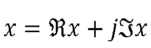
Let Lb be the Log Likelihood Ratio (LLR) of bit b in symbol x. The Max-Log-MAP Log Likelihood Ratio (LLR) is:
where the minima are taken over all possible constellation values x, respectively x', subject to bit b is equal to 1, respectively 0. - The norm can be developed as

- Any constant term independent of the minimization, such as ||Y||2, cancels out after subtracting the two minima. Hence, it is sufficient to consider the norm:

- As can be seen, such expression has much lower implementation complexity regarding the classical expression of Zero-Forcing (ZF) solution of the prior art

- Furthermore, such expression is the sum of real and imaginary parts:

- Considering for example a bit mapped to the real axis, the variableis independent of variable
 x, which permits minimizing the real part separately (and vice versa). In the next subsections, a focus is made on the variable
 x but the same can be inferred directly and unambiguously for variable
 x.
x.
- Considering that according to the invention the real part can be expressed as:

with x and corresponding minimum norm by implementing simple shifts registers, which implement some operations of multiplication or division by powers of two, additions and comparisons, assuming
 x ∈ {±1, ±3, ±5, ±7...}, (
 x)2 ∈ {1,9,25,49,...}. This assumption requires pre-normalization, for example of H, by the constellation's Root Mean Square (RMS).
- By multiplying
 x is obtained as the
 x that is nearest to β, or equivalently finding the decision region containing β, where the decision regions are bounded by {..., -6α, -4α, -2α, 0,2α, 4α, 6α, ... }.
- According to an example, the step of selecting implements a hard-symbol slicing that selects the nearest symbol on the real (or imaginary) axis. For instance, for 64QAM there are eight decision regions. A binary search with three comparisons can quickly yield the result. An example of binary search for 64QAM: β > 0 then β < 4α then β > 2α, yielding β ∈ [2α, 4α] andx = 3.

- After the previous step of slicing deliveringx (respectively
 x), the step of determining (22) the Euclidian distance between the received signal Y and the data signal transmitted using said candidate value multiplied by said channel matrix H, weighted by the inverse of a noise covariance matrix C according to the invention is performed by using the following expression:

- Especially, according to the invention, the terms depending on α are computed by adding (220) to each of them a predetermined constant depending on the size of the constellation of the layer k, called a constellation dependent constant. In other words, it is proposed to "virtually" add or subtract constant terms from both minima to further reduce the norm's complexity.
- For instance, for a 64QAM constellation, by subtracting from the norm the constellation dependent constant 25||H||2 = 25α, a set of terms easier to compute is obtained: α((x)2-25) ∈ {0, -16α, ±24α}

- The subtraction of the constellation dependent constant 25α does not alter the Log Likelihood Ratio (LLR) value.
- According to other examples, for both a QPSK and a 16QAM ||H||2 can be subtracted to obtain, respectively, the sets α((x)2 - 1) ∈ {0} and α((
 x)2 - 1) ∈ {0, 8α}.
- According to another example, for a 16QAM, 5||H||2 could be alternatively subtracted to obtain the set α((x)2 - 5) ∈ {-4α, 4α}.

- Thus, a rule can be applied, which consists in subtracting a "virtual" number, called a constellation dependent constant, to reduce the total number of bits in the binary representation of the resulting set of norms (hence minimizing number of additions), and in considering that negative numbers can be obtained from positive numbers with a simple negation operation.
- In a complementary and optimal way, the invention proposes to maintain some symmetry between positive and negative numbers in order to reduce the dynamic range of the norms (for fixed pointing considerations). An optimized constellation dependent constant to subtract in this case is the mid-range (1 + max(x)2)/2, which makes the positive and negative dynamic ranges equal. For instance, this number is 1 for QPSK, 5 for 16QAM, 25 for 64QAM, 113 for 256QAM, 481 for 1024QAM, etc.

- Likewise and considering the same example based on a 64QAM constellation, an enhancement can be achieved by subtracting the constant term 2H H Y ≡ 2β then 2β(
 x + 1) ∈ {0, ±4β, ±8β, ±12β, 16β) and consists of one addition, two negations and plain shifts. For QPSK and 16QAM respectively, the sets 2β(
 x + 1) ∈ (0, 4β} and 2β(
 x + 1) ∈ {0, ±4β, 8β} are obtained.
- Moreover, scaling by 1/σ 2 can be either applied to the output Log Likelihood Ratio (LLR), or embedded in the two primary dot products,


- The step of determining (22) according to the invention delivers a Euclidian distance for a data signal that comprises data symbols transmitted over a single layer. Such a Euclidian distance is then used for an enhancement step using for instance turbo-decoding.
- According to another example, a soft-decision is obtained for some bits (bit interleaved coded modulation) by subtracting the distances of two previous hard-decisions using a hard-symbol slicing as described above (where the two hard-decisions are obtained from two distinct constellations, e.g. one constellation for the bit equal to 0, and the other constellation for the bit equal to 1).
- For instance, for each bit b fixed to either 1 or 0, a subset of allowed symbols is obtained. For each subset, selecting the nearest symbol is implemented using a hard-symbol slicer. For instance, for Gray coded 64QAM, there are three bits per dimension with
values 1xx -7 -5 -3 -1 . . . . 0xx . . . . +1 +3 +5 +7 x1x -7 -5 . . . . +5 +7 x0x . . -3 -1 +1 +3 . . xx1 -7 . . -1 +1 . . +7 xx0 . -5 -3 . . +3 +5 . -7 -5 -3 -1 -1 -1 -1 -1 +1 +1 +1 +1 +1 +3 +5 +7 -7 -5 -5 -5 +5 +5 +5 +7 -3 -3 -3 -1 +1 +3 +3 +3 -7 -7 -1 -1 +1 +1 +7 +7 -5 -5 -3 -3 +3 +3 +5 +5 x = -7, i.e. the first constellation symbol, then the first column is the winning column. The table can consist of indexes rather than symbol values.
- In the presence of colored noise or interference with covariance matrix C, the Max-Log-MAP Log Likelihood Ratio (LLR) with interference mitigation is:

where the notation with subscript C-1 indicates weighted norm,
- The only change with respect to a Gaussian Noise, is the replacement of the two terms


- Thus, taking into account a colored noise instead of a Gaussian noise involves replacing the two primary dot products by weighted dot products. Consequently, for minimal complexity and power consumption, the data path Y is unaltered while the channel estimation path is modified to provide H and C-1H (for fixed point, a per-block exponent can handle large variations of signal o noise ratio (SNR) between blocks).
- In comparison with the proposed solution of the invention for taking into account a colored noise, noise pre-whitening has higher complexity and power consumption since it requires a Cholesky decomposition and it is applied to the data path.
- Moreover, since C-1 and H are slowly changing signals, C-1H can be (approximately) interpolated to adjacent symbols or subcarriers, similarly to H, which can dramatically reduce complexity of this product. This is illustrated in 3. The interpolation trick cannot be used by the Cholesky decomposition C-1/2 applied to the data path, C-1/2Y, since Y is a fast varying signal.
- The classical linear Minimum Mean Square Error (MMSE) equalizer for multi-layers can be expressed using the expressions stated above for a data signal comprising data symbols transmitted over one single layer for a selected layer xi to decode, while the remaining layers other than the one processed as described above are treated as Gaussian distributed colored noise.
- Such an implementation of the Minimum Mean Square Error (MMSE) equalizer is lower cost than the traditional unbiased Minimum Mean Square Error (MMSE) with signal to noise ratio (SNR) weighting.
- In this application, a unique matrix can be inverted, which is


where


- Thus, for a two antennas receiver, inverting 2x2 matrix


- In this embodiment, thus regarding the general expression given above simplifications can be made since i=j, et



- In other words, it is considered that the data signal comprises data symbol x transmitted over two
layers layer 0 andlayer 1 with for each layer possibly different constellation order, and considering that each layer is carried by its own beam or channel, H0 and H1,
- For the first layer, let L 0b be the Log Likelihood Ratio (LLR) of bit b in symbol x 0. For the second layer, let L 1b be the Log Likelihood Ratio (LLR) of bit b in symbol x 1. For instance, the
first layer 0 is considered to be the layer of interest, in other terms the layer for which it is desired to obtain the optimized value of the symbol x0. - The
second layer 1 can be obtained by reversing the roles of first and second layers. In some cases, the second layer is an unwanted interferer and there is no need to compute L1b. For symbol x 0, the Max-Log-MAP Log Likelihood Ratio (LLR) with colored interference is:
where the minima are taken over all possible constellation values x 0, x 1 subject to bit b of symbol x 0 is equal to 1, and over all possible constellation values x' 0, x' 1 subject to bit b of symbol x 0 is equal to 0. - In the following, for a simpler notation, C-1 is omitted from the dot products but it is implicitly assumed that all dot products and norms are weighted by C-1, in particular the five primary dot products

- To find L 0b , the two substeps of selecting (21) and determining an Euclidian distance (22) are performed. In the following, for a layer k, K is the constellation size, e.g. K = 64.
- According to the invention, the substep of selecting consists in choosing a candidate value for the
layer 1 by using for example a hard-symbol slicer. - Thus, such a substep of selecting delivers the symbol x 1 that is used subsequently in the substep of determining an Euclidian distance to determine the optimized symbol x 0.
- Note that x 1 comes from constellation of
layer 1, which can have different constellation order than constellation oflayer 0. For example, the constellation oflayer 1 is 64QAM, whereas the constellation oflayer 0 is QPSK. - Such a selection reduces the number of operations since it avoids the test of all the possible values of the constellation of the
layer 1 since only one value is tested among all the values of the possible values of the constellation. - Once the candidate value x 1 has been fixed, the method involves computing K Euclidian distance or norms, for each constellation symbol x 0p (p = 0 .. K - 1), ||Y k - (H0 x 0 + H1 x 1 )||2,
- According to the invention, for each x 0k , the norm ||Y k - (H0 x 0 + H1 x 1)||2 is expressed as the sum of the two norms

- Such expression is easier to implement since it requires less complex operations.
- In addition, according to the invention and considering the example of a 64QAM for
layer 0 andlayer 1, a constellation dependent constant equal to 25 is added and/or subtracted and the terms

and for the imaginary part a similar expression can obtained starting from the imaginary expression:
- Considering other examples, like a QPSK or a 16QAM, the constellation dependent constant is respectively equal to 1 or 5.
- For x 0k , the norm α 0((x 0k )2 - 25) - 2β 0(
 x 0k + 1) can be pre-computed with a few additions and then summed up for each combination of
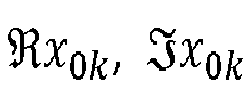 x 0k )2 - 25) - 2β 0(
 x 0k + 1) is obtained considering the constellation order of
layer 0 as being 64QAM but would be different considering another constellation (QPSK, 16QAM, etc.) as already explained above. - For x 1, to save additions down the road, norm


- Then for a given x 0k and after selecting (21) the candidate value for x 1, norm α 1((x 1)2 - 25) - 2β 1(
 x 1 + 1) can be obtained via maximum four additions, or an average two and a half additions (including adding up the norms for

 x 1)2 - 25)).
- Since there are 64 values of x 0k , then a maximum of 4x64 additions is obtained. Note that the constellation dependent constant 25 of α 1((x 1)2 - 25) - 2β 1(
 x 1 + 1) is obtained considering the constellation order of
layer 1 as being 64QAM but would be different considering another constellation (QPSK, 16QAM, etc.) as already explained above. - The last remaining terms to be computed are β 1k R and β 1k I , expressed as following:

and it can be rearranged as
and for the imaginary part :
rearranged as
- In these above expressions terms similar


 x 0k )2 - 25) - 2β 0(
 x 0k + 1) + α 1((
 x 1)2 - 25) - 2β 1k R (
 x 1 + 1) and α 0((
 x 0k )2 - 25) - 2β 0(
 x 0k + 1) + α 1((
 x 1)2 - 25) - 2β 1k 1 (
 x 1 + 1) are respectively obtained using 64 additions for the real part and the imaginary part respectively.
- In summary, for 64QAM the proposed maximum likelihood method for decoding according to the invention requires 2x8x64 = 1024 additions for both L 0b and L 1b , plus a few more in the pre-computing phase, and plus five primary dot products. More accurate complexity for 64QAM is 16R real multiplications and 1090 + 16n r real additions where n r is number of receiving antennas (excluding inverse noise covariance weighting).
- In addition, advantageously, according to a variant of this method applied to a data signal comprising data symbols transmitted over two layers there are more simplifications.
- Indeed,
 x 0 + 1 and
 x 1 + 1 requires subtracting non-constant term


- Then, the constellation dependant constant can be added as already described above.
- Then and optionally, a soft-bit decision step is performed to get the probabilities of the bit values of the symbol of each layer.
- In other words, the substeps of the method according to the invention including a step of soft-bit decision are first implemented considering that the current layer is
layer 0, which delivers the probabilities of the bit values of x0, and then repeated considering that the current layer islayer 1, which delivers the probabilities of the bit values of x1. In other words, the "roles" of thelayer 0 and of thelayer 1 are reversed. - Such an embodiment is a variant to process a signal comprising data symbols transmitted in more than two layers and is illustrated by
figure 4 . - More precisely, according to this embodiment, when said signal comprises a set of data symbols transmitted in N>2 layers, the method comprises S≤N iterations, each iteration processing Q<N layers, while the other (N-Q) layers are included in said covariance matrix C, and delivering transmitted symbols of R≤ (Q - 1) layers of said Q first layers, called resulting layers, one iteration processing Q layers being different from the resulting layers issued by the previous iterations, Q, R, S being integers able to be different from one iteration to the other.
- In particular,
figure 4 represents an example of such embodiment where Q=2. - Such embodiment permits to obtain the whole N optimized values by processing the layers two layers by two layers in N iterations. Such a process permits to reduce the complexity of an iteration since as seen above processing a data signal comprising symbols transmitted over two layers involves les complex operations than processing a data signal comprising symbols transmitted over N layers.
- Such embodiment is particularly adapted when some of the transmitted layers have a QAM (quadrature amplitude modulation) constellation distribution and some have Gaussian distribution, and permits to use an hybrid detector using both maximum likelihood detection (MLD) and Minimum Mean Square Error (MMSE).
- It consists in finding the nearest points in a multi-dimensional constellation with the distances weighted by colored Gaussian noise. This detector can be implemented as maximum likelihood detection (MLD) for the non-Gaussian layers while using a colored noise covariance matrix that includes the remaining Gaussian layers. I.e. Minimum Mean Square Error (MMSE) equalization of Gaussian layers is incorporated in the noise covariance matrix.
- To reduce maximum likelihood detection (MLD) complexity, some of the less interfering layers can be approximated with a Gaussian distribution since Minimum Mean Square Error (MMSE) equalization is less costly.
- In fact, traditional Minimum Mean Square Error (MMSE) equalizer implicitly isolates one layer of interest and treats all remaining layers as colored Gaussian noise. Minimum Mean Square Error (MMSE) equalizer can thus be viewed as implementing the method described in the first embodiment for a data signal comprising data symbols transmitted in a single layer with the remaining layers included in the noise covariance. The operation is repeated for each layer of interest.
- Here such a classical principle of the Minimum Mean Square Error (MMSE) equalizer is extended to process two (or more for example a number of layers equal to Q<N, where Q is an integer superior to two) layers for delivering a given layer of interest, treating the two (or more) isolated layers with the maximum likelihood technique of the invention as described in the second embodiment, and the remaining layers with Minimum Mean Square Error (MMSE) as colored Gaussian noise. The operation is repeated for each layer of interest.
- For example, such a hybrid combination of the maximum likelihood detection (MLD) and Minimum Mean Square Error (MMSE) can be combined to achieve multi-layer detection.
- As illustrated by
figure 4 , the multiple layers are split into two groups: two layers are selectively picked for the maximum likelihood detection according to the second embodiment, and the additional layers are processed as colored interference with known covariance matrix (Minimum Mean Square Error (MMSE) group). - The Minimum Mean Square Error (MMSE) group is essentially treated similarly to linear Minimum Mean Square Error (MMSE) equalization, and it implicitly assumes Gaussian distribution of the symbol carried by each layer.
- For the maximum likelihood detection (MLD) group, the first selected layer, H ixi , is the layer to decode, i.e. the layer of interest. The second selected layer, H jxj , is, for example, the layer that interferes most with the first layer (constellation order can also be part of the selection criteria: selecting an interfering layer with a low constellation order improves maximum likelihood detection (MLD) robustness, since Max-Log-MAP maximum likelihood detection (MLD) relies on selecting a candidate value for the interfering layer; a third criteria for the selection can be based on predicting the equalizer's output SNR per selection). The second layer will not be decoded at this point.
- The layer that interferes most with first layer i is given by
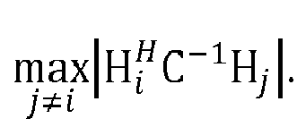

- After the symbol xi is decoded, the steps of the method according to the invention are performed for another layer i' that we wish to decode.
- In principle, the algorithm requires several matrix inversions. But this can be resolved by:
- inverting a unique signal covariance matrix

- subtracting layer of interest i via matrix inversion lemma

where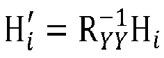

- subtracting interfering layer j while performing primary dot products starting with
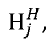


- In other examples, a larger number Q of layers (3, 4, etc.) can be selected and processed thanks to the method according to the invention, which uses a maximum likelihood detection and treat all remaining layers with Minimum Mean Square Error as if they were Gaussian distributed. In addition, Q can be different from one iteration to the other.
- In the previous description of embodiments, it is assumed that for all constellation symbols xi and xj different from the constellation symbol xn of the current layer n, an exhaustive search using a maximum likelihood technique for setting values of the constellation symbols xi and xj .
- To further reduce the complexity of the method it is now assumed that for constellation symbols xi of at least one layer i different from the current layer n, a search is limited to a predetermined region of the constellation symbols xi . Such a variant is represented by
figures 5 and 6 . - More precisely, for example, a pre-stage using a Minimum Mean Square Error (MMSE) equalizer is used to select a subset (61) of candidate values for x 0 the symbol of the
layer 0 of interest. This can be achieved, for example, by processing norm

- The subset of candidate values for x 0 is obtained using a hard-symbol slicer as described above, but instead of outputting one single hard-symbol, several nearest symbols are outputted; for example five nearest real symbols

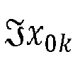
figure 6 . - Then such a subset is used as an input of the maximum likelihood detection (MLD) method of the invention. It is a simple modification to the maximum likelihood detection (MLD) method and is particularly useful for processing multi-layers data signal or for large constellations, such as 1024QAM.
- The solution can be viewed as a concatenation of Minimum Mean Square Error (MMSE) equalizer followed by maximum likelihood detection (MLD) according to the invention on a reduced set as illustrated by
figure 5 . - The pre-stage of slicing x 0 essentially focuses on
layer 0 while assuming other layers such aslayer 1 as Gaussian distributed (Gaussian noise). It acts like Minimum Mean Square Error slicing but instead of limiting the number of outputs to a unique hard-symbol, it finds a square (or rectangular or circular...) region around the initial Zero Forcing candidate as illustrated byfigure 6 . - The square region (61) is extended to other lattice dimensions for the other layers, and the overall search region has the shape of a hyper-parallelepiped (or hyper-cylinder).
- Minimum Mean Square Error (MMSE) equalization can be efficiently performed as explained above, i.e. a unique matrix can be inverted,

- After the initial stage, the steps of the method according to the invention are performed considering a
current layer 1 for example, with a size of possible values x 0k to parse, which is now 25 instead of 64, for example. - A reduction of about 50% is thus achieved in this example, traded against a slight performance loss.
- An issue to keep in mind is that, if the search region is too tight, the minima search stage may not find any x 0k available in the list for some bit b. A remedy is to carefully pick the near symbols (not always the nearest neighbors) in the constellation such that it is guaranteed that all bits b will have non-empty list of x 0k .
- For instance, for 64QAM, choosing the five nearest constellation points guarantees non-empty lists.
- If the search region is further tightened such that some lists remain empty, then a solution can be to use the Log Likelihood Ratio (LLR) that can be obtained from the pre-stage of MMSE (or to set the corresponding the Log Likelihood Ratio (LLR) to infinity).
- Finally, referring to
figure 7 , the simplified structure is presented of a decoder respectively implementing a method for decoding as described here above. - An encoding device, as illustrated in
figure 7 , comprises amemory 71 comprising a buffer memory, aprocessing unit 72 equipped for example with a microprocessor µP and driven by thecomputer program 73, implementing the method for decoding according to the invention. At initialization, the code instructions of thecomputer program 73 are for example loaded into a RAM and then executed by the processor of theprocessing unit 72. Theprocessing unit 72 receives a current data signal to be decoded. The microprocessor of the processing unit 62 implements the steps of the method for decoding described here above according to the computer program instructions 63 to encode the current image. To this end, the decoder comprises, in addition to thebuffer memory 61, means for means for detecting that determines the maximum likelihood for at least one data symbol of said data signal. Said means for detecting comprises: - means for selecting one candidate value for the data symbol of the current layer n,
- means for determining the Euclidian distance between the received signal Y and the data signal transmitted using said candidate value multiplied by said channel matrix H, weighted by the inverse of a noise covariance matrix C such as


wherein:- H k is a vector representing the channel associated to a layer k, with k E {i, j, n}, i, j, n ∈ [0, N - 1], i, j, n being integers, possibly equal and N being the number of layers of said data signal;
- xk is the constellation symbol of the layer k;


- These means are driven by the microprocessor of the processing unit 62.


where:


wherein:
Claims (16)
- A method for decoding a received signal Y corresponding to a data signal transmitted in a MIMO communication system through a channel represented by a channel matrix H, said data signal comprising a set of data symbols x transmitted in at least one layer, each layer carrying at least one data symbol belonging to a signal constellation,
said method comprises, for one of said at least one layer, called a current layer n, a detection step that determines the maximum likelihood for at least one data symbol of said data signal, wherein said detection step (20) comprises:- selecting (21) one candidate value for the data symbol of the current layer n,- determining (22) the Euclidian distance between the received signal Y and the data signal transmitted using said candidate value multiplied by said channel matrix H, weighted by the inverse of a noise covariance matrix C such aswherein:
 H k is a vector representing the channel associated to a layer k, with k E {i, j, n}, i, j, n ∈ [0, N - 1], i, j, n being integers, possibly equal and N being the number of layers of said data signal;xk is the constellation symbol of the layer k;


 wherein the terms depending on αk are computed by adding (220) to each of them a predetermined constant depending on the size of the constellation of the layer k, called a constellation dependent constant.
 - The method for decoding according to claim 1, wherein said constellation dependent constant is equal to (1 + max(x)2)/2, where max(
 x) corresponds to the maximum real part of the candidate values of said constellation of the layer k.
- The method for decoding according to anyone of the preceding claims, wherein the terms depending on βk are computed by adding the constant 2.M.βk to each of them, where M is an integer.
- The method for decoding according to anyone of the preceding claims, wherein it comprises, for all constellation symbols xi and xj different from the constellation symbol xn of the current layer n, an exhaustive search using a maximum likelihood technique for setting values of the constellation symbols xi and xj .
- The method for decoding according to anyone of the preceding claims, wherein it comprises, for constellation symbols xi at of at least one layer i different from the current layer n, a search in a predetermined region of the constellation symbols xi .
- The method for decoding according to anyone of the preceding claims, wherein said current layer n is the layer with the highest constellation order.
- The method for decoding according to anyone of the preceding claims, wherein when said signal comprises a set of data symbols transmitted in one layer, i=j=n=0 and


- The method for decoding according to anyone of the claims 1 to 6, wherein when said signal comprises a set of data symbols transmitted in two layers, i=j, et i, n ∈ [0,1]


- The method for decoding according to claim 7, wherein when the terms depending on βk are computed by adding the constant 2.M.βk to each of them, where M is an integer and considering that

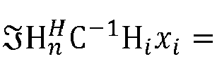


- The method for decoding according to anyone of the preceding claims, wherein it comprises a subsequent step of decoding, for example a turbo-decoding.
- The method for decoding according to anyone of the preceding claims, wherein when the noise is a white Gaussian noise, the noise covariance matrix C is equal to σ 2 I, where I is the identity matrix and σ 2 is the variance of said white Gaussian noise.
- The method for decoding according to anyone of the preceding claims, wherein said step of selecting one candidate value for the data symbol of the current layer n implements a hard-symbol slicing.
- The method for decoding according to anyone of the preceding claims, wherein said method implements a soft-bit decision step.
- The method for decoding according to claims 8 or 9, wherein when said signal comprises a set of data symbols transmitted in N>2 layers, the method comprises S≤N iterations, each iteration processing Q<N layers, while the other (N-Q) layers are included in said covariance matrix C, and delivering transmitted symbols of R≤ (Q - 1) layers of said Q first layers, called resulting layers, one iteration processing Q layers being different from the resulting layers issued by the previous iterations, Q, R, S being integers able to be different from one iteration to the other.
- A decoder for decoding a received signal Y corresponding to a data signal transmitted in a MIMO communication system through a channel represented by a channel matrix H, said data signal comprising a set of data symbols x transmitted in at least one layer, each layer carrying at least one data symbol belonging to a signal constellation,
said decoder comprises, for one of said at least one layer, called a current layer n, means for detecting that determines the maximum likelihood for at least one data symbol of said data signal,
wherein said means for detecting comprises:- means for selecting one candidate value for the data symbol of the current layer n,- means for determining the Euclidian distance between the received signal Y and the data signal transmitted using said candidate value multiplied by said channel matrix H, weighted by the inverse of a noise covariance matrix C such aswherein:
 H k is a vector representing the channel associated to a layer k, with k E {i, j, n}, i, j, n ∈ [0, N - 1], i, j, n being integers, possibly equal and N being the number of layers of said data signal;xk is the constellation symbol of the layer k;



 wherein the terms depending on αk are computed by adding to each of them a predetermined constant depending on the size of the constellation of the layer k, called a constellation dependent constant.
 - A computer program product downloadable from a communications network and/or stored on a computer readable support and/or executable by a microprocessor, said computer program product comprising program code instructions for implementing a method for decoding a received signal Y corresponding to a data signal transmitted in a MIMO communication system through a channel represented by a channel matrix H, said data signal comprising a set of data symbols x transmitted in at least one layer, each layer carrying at least one data symbol belonging to a signal constellation,
wherein said computer program product comprises program code instructions for processing for one of said at least one layer, called a current layer n, a detection step that determines the maximum likelihood for at least one data symbol of said data signal,
wherein said detection step comprises:- selecting one candidate value for the data symbol of the current layer n,- determining the Euclidian distance between the received signal Y and the data signal transmitted using said candidate value multiplied by said channel matrix H, weighted by the inverse of a noise covariance matrix C such aswherein:

H k is a vector representing the channel associated to a layer k, with k E {i, j, n}, i, j, n ∈ [0, N - 1], i, j, n being integers, possibly equal and N being the number of layers of said data signal;
xk is the constellation symbol of the layer k;


wherein the terms depending on αk are computed by adding to each of them a predetermined constant depending on the size of the constellation of the layer k, called a constellation dependent constant.
Applications Claiming Priority (1)
| Application Number | Priority Date | Filing Date | Title |
|---|---|---|---|
| US13/598,161 US8711958B2 (en) | 2012-08-29 | 2012-08-29 | Method for decoding a spatially multiplexed data signal using a maximum likelihood detection |
Publications (3)
| Publication Number | Publication Date |
|---|---|
| EP2704384A2 true EP2704384A2 (en) | 2014-03-05 |
| EP2704384A3 EP2704384A3 (en) | 2015-10-14 |
| EP2704384B1 EP2704384B1 (en) | 2016-11-02 |
Family
ID=49028917
Family Applications (1)
| Application Number | Title | Priority Date | Filing Date |
|---|---|---|---|
| EP13181007.9A Not-in-force EP2704384B1 (en) | 2012-08-29 | 2013-08-20 | Method for decoding a spatially multiplexed data signal using a maximum likelihood detection |
Country Status (2)
| Country | Link |
|---|---|
| US (1) | US8711958B2 (en) |
| EP (1) | EP2704384B1 (en) |
Cited By (1)
| Publication number | Priority date | Publication date | Assignee | Title |
|---|---|---|---|---|
| EP4236104A1 (en) * | 2022-02-24 | 2023-08-30 | Ceva D.S.P. Ltd. | System and method for using low complexity maximum likelihood decoder in a mimo decoder |
Families Citing this family (4)
| Publication number | Priority date | Publication date | Assignee | Title |
|---|---|---|---|---|
| CN103634078B (en) * | 2012-08-20 | 2017-02-08 | 中兴通讯股份有限公司 | Processing method and device for performing space-time decoding on MIMO signal |
| US9325427B1 (en) * | 2012-10-31 | 2016-04-26 | Ciena Corporation | Maximum likelihood decoding |
| CN110063046A (en) * | 2016-06-08 | 2019-07-26 | 华为技术有限公司 | Receiving device and method thereof |
| JP2021149286A (en) * | 2020-03-17 | 2021-09-27 | キオクシア株式会社 | Learning device |
Family Cites Families (3)
| Publication number | Priority date | Publication date | Assignee | Title |
|---|---|---|---|---|
| US7489746B1 (en) * | 2004-04-22 | 2009-02-10 | Qualcomm, Inc. | MIMO receiver using maximum likelihood detector in combination with QR decomposition |
| ATE434296T1 (en) | 2006-04-05 | 2009-07-15 | Sequans Comm | METHOD FOR DECODING A SPACIALLY MULTIPLEXED SIGNAL AND CORRESPONDING RECEIVER |
| US20110150147A1 (en) * | 2009-12-23 | 2011-06-23 | Xuebin Yang | Device, system and method of multiple-input-multiple-output wireless communication |
-
2012
- 2012-08-29 US US13/598,161 patent/US8711958B2/en active Active
-
2013
- 2013-08-20 EP EP13181007.9A patent/EP2704384B1/en not_active Not-in-force
Non-Patent Citations (1)
| Title |
|---|
| None |
Cited By (2)
| Publication number | Priority date | Publication date | Assignee | Title |
|---|---|---|---|---|
| EP4236104A1 (en) * | 2022-02-24 | 2023-08-30 | Ceva D.S.P. Ltd. | System and method for using low complexity maximum likelihood decoder in a mimo decoder |
| US12057986B2 (en) | 2022-02-24 | 2024-08-06 | Ceva Technologies, Ltd | System and method for using low complexity maximum likelihood decoder in a mimo decoder |
Also Published As
| Publication number | Publication date |
|---|---|
| US20140062733A1 (en) | 2014-03-06 |
| EP2704384A3 (en) | 2015-10-14 |
| EP2704384B1 (en) | 2016-11-02 |
| US8711958B2 (en) | 2014-04-29 |
Similar Documents
| Publication | Publication Date | Title |
|---|---|---|
| EP2104981B1 (en) | Antenna selection and soft demapping for mimo decoding | |
| EP1905182B1 (en) | Apparatus and method for detecting communications from multiple sources | |
| US8121220B1 (en) | Apparatus and method for reduced complexity maximum likelihood MIMO detection | |
| EP2293483B1 (en) | Method and device for soft-output detection in multiple antenna communication systems | |
| EP2293504B1 (en) | Method and apparatus for interference mitigation in a baseband OFDM receiver | |
| US10819468B2 (en) | Stochastic linear detection | |
| EP2458747A1 (en) | Detection process for a receiver of a wireless MIMO communication system | |
| CN107094063B (en) | Semi-exhaustive iterative block decoding method and device | |
| EP2704384B1 (en) | Method for decoding a spatially multiplexed data signal using a maximum likelihood detection | |
| US7848440B2 (en) | Multi-channel communication method and apparatus using plural Markov Chain Monte Carlo simulations | |
| CN107276716A (en) | Method and apparatus for decoding data signal | |
| EP3229428A1 (en) | Methods and devices for sequential sphere decoding | |
| EP2830271B1 (en) | Low complexity maximum-likelihood-based method for estimating emitted symbols in a sm-mimo receiver | |
| US20120263080A1 (en) | Apparatus and method for detecting signal in spatial multiplexing system | |
| KR101121069B1 (en) | Method for the flexible demodulation of estimated complex symbols | |
| JP5288622B2 (en) | Wireless communication apparatus, wireless communication system, and communication method | |
| EP2680520B1 (en) | Method and apparatus for efficient MIMO reception with reduced complexity | |
| EP1895727B1 (en) | Equalizing structure based on a List MLD detection scheme and a corresponding method | |
| EP1895729B1 (en) | Equalizing structure and equalizing method | |
| EP1931075B1 (en) | Method of decoding of a received multidimensional signal | |
| Lofgren et al. | On MIMO K-best sphere detector architecture complexity reductions | |
| US9917723B2 (en) | Efficient methods and recursive/scalable circuit architectures for QAM symbol mean and variance estimations | |
| CN116938394B (en) | MIMO detection method, receiving method and system | |
| EP1912367B1 (en) | Method of decoding of a received multidimensional signal and corresponding device | |
| Ali | On Lattice Sequential Decoding for Large MIMO Systems |
Legal Events
| Date | Code | Title | Description |
|---|---|---|---|
| AK | Designated contracting states |
Kind code of ref document: A2 Designated state(s): AL AT BE BG CH CY CZ DE DK EE ES FI FR GB GR HR HU IE IS IT LI LT LU LV MC MK MT NL NO PL PT RO RS SE SI SK SM TR |
|
| AX | Request for extension of the european patent |
Extension state: BA ME |
|
| PUAI | Public reference made under article 153(3) epc to a published international application that has entered the european phase |
Free format text: ORIGINAL CODE: 0009012 |
|
| RAP1 | Party data changed (applicant data changed or rights of an application transferred) |
Owner name: SEQUANS COMMUNICATIONS |
|
| PUAL | Search report despatched |
Free format text: ORIGINAL CODE: 0009013 |
|
| AK | Designated contracting states |
Kind code of ref document: A3 Designated state(s): AL AT BE BG CH CY CZ DE DK EE ES FI FR GB GR HR HU IE IS IT LI LT LU LV MC MK MT NL NO PL PT RO RS SE SI SK SM TR |
|
| AX | Request for extension of the european patent |
Extension state: BA ME |
|
| RIC1 | Information provided on ipc code assigned before grant |
Ipc: H04L 25/06 20060101AFI20150907BHEP Ipc: H04L 25/03 20060101ALI20150907BHEP |
|
| 17P | Request for examination filed |
Effective date: 20160208 |
|
| RBV | Designated contracting states (corrected) |
Designated state(s): AL AT BE BG CH CY CZ DE DK EE ES FI FR GB GR HR HU IE IS IT LI LT LU LV MC MK MT NL NO PL PT RO RS SE SI SK SM TR |
|
| GRAP | Despatch of communication of intention to grant a patent |
Free format text: ORIGINAL CODE: EPIDOSNIGR1 |
|
| INTG | Intention to grant announced |
Effective date: 20160701 |
|
| GRAS | Grant fee paid |
Free format text: ORIGINAL CODE: EPIDOSNIGR3 |
|
| GRAA | (expected) grant |
Free format text: ORIGINAL CODE: 0009210 |
|
| AK | Designated contracting states |
Kind code of ref document: B1 Designated state(s): AL AT BE BG CH CY CZ DE DK EE ES FI FR GB GR HR HU IE IS IT LI LT LU LV MC MK MT NL NO PL PT RO RS SE SI SK SM TR |
|
| REG | Reference to a national code |
Ref country code: GB Ref legal event code: FG4D |
|
| REG | Reference to a national code |
Ref country code: AT Ref legal event code: REF Ref document number: 842816 Country of ref document: AT Kind code of ref document: T Effective date: 20161115 Ref country code: CH Ref legal event code: EP |
|
| REG | Reference to a national code |
Ref country code: IE Ref legal event code: FG4D |
|
| REG | Reference to a national code |
Ref country code: DE Ref legal event code: R096 Ref document number: 602013013408 Country of ref document: DE |
|
| PG25 | Lapsed in a contracting state [announced via postgrant information from national office to epo] |
Ref country code: LV Free format text: LAPSE BECAUSE OF FAILURE TO SUBMIT A TRANSLATION OF THE DESCRIPTION OR TO PAY THE FEE WITHIN THE PRESCRIBED TIME-LIMIT Effective date: 20161102 |
|
| REG | Reference to a national code |
Ref country code: NL Ref legal event code: MP Effective date: 20161102 |
|
| REG | Reference to a national code |
Ref country code: LT Ref legal event code: MG4D |
|
| REG | Reference to a national code |
Ref country code: AT Ref legal event code: MK05 Ref document number: 842816 Country of ref document: AT Kind code of ref document: T Effective date: 20161102 |
|
| PG25 | Lapsed in a contracting state [announced via postgrant information from national office to epo] |
Ref country code: NO Free format text: LAPSE BECAUSE OF FAILURE TO SUBMIT A TRANSLATION OF THE DESCRIPTION OR TO PAY THE FEE WITHIN THE PRESCRIBED TIME-LIMIT Effective date: 20170202 Ref country code: NL Free format text: LAPSE BECAUSE OF FAILURE TO SUBMIT A TRANSLATION OF THE DESCRIPTION OR TO PAY THE FEE WITHIN THE PRESCRIBED TIME-LIMIT Effective date: 20161102 Ref country code: LT Free format text: LAPSE BECAUSE OF FAILURE TO SUBMIT A TRANSLATION OF THE DESCRIPTION OR TO PAY THE FEE WITHIN THE PRESCRIBED TIME-LIMIT Effective date: 20161102 Ref country code: GR Free format text: LAPSE BECAUSE OF FAILURE TO SUBMIT A TRANSLATION OF THE DESCRIPTION OR TO PAY THE FEE WITHIN THE PRESCRIBED TIME-LIMIT Effective date: 20170203 Ref country code: SE Free format text: LAPSE BECAUSE OF FAILURE TO SUBMIT A TRANSLATION OF THE DESCRIPTION OR TO PAY THE FEE WITHIN THE PRESCRIBED TIME-LIMIT Effective date: 20161102 |
|
| PG25 | Lapsed in a contracting state [announced via postgrant information from national office to epo] |
Ref country code: PT Free format text: LAPSE BECAUSE OF FAILURE TO SUBMIT A TRANSLATION OF THE DESCRIPTION OR TO PAY THE FEE WITHIN THE PRESCRIBED TIME-LIMIT Effective date: 20170302 Ref country code: AT Free format text: LAPSE BECAUSE OF FAILURE TO SUBMIT A TRANSLATION OF THE DESCRIPTION OR TO PAY THE FEE WITHIN THE PRESCRIBED TIME-LIMIT Effective date: 20161102 Ref country code: RS Free format text: LAPSE BECAUSE OF FAILURE TO SUBMIT A TRANSLATION OF THE DESCRIPTION OR TO PAY THE FEE WITHIN THE PRESCRIBED TIME-LIMIT Effective date: 20161102 Ref country code: PL Free format text: LAPSE BECAUSE OF FAILURE TO SUBMIT A TRANSLATION OF THE DESCRIPTION OR TO PAY THE FEE WITHIN THE PRESCRIBED TIME-LIMIT Effective date: 20161102 Ref country code: IS Free format text: LAPSE BECAUSE OF FAILURE TO SUBMIT A TRANSLATION OF THE DESCRIPTION OR TO PAY THE FEE WITHIN THE PRESCRIBED TIME-LIMIT Effective date: 20170302 Ref country code: FI Free format text: LAPSE BECAUSE OF FAILURE TO SUBMIT A TRANSLATION OF THE DESCRIPTION OR TO PAY THE FEE WITHIN THE PRESCRIBED TIME-LIMIT Effective date: 20161102 Ref country code: HR Free format text: LAPSE BECAUSE OF FAILURE TO SUBMIT A TRANSLATION OF THE DESCRIPTION OR TO PAY THE FEE WITHIN THE PRESCRIBED TIME-LIMIT Effective date: 20161102 Ref country code: ES Free format text: LAPSE BECAUSE OF FAILURE TO SUBMIT A TRANSLATION OF THE DESCRIPTION OR TO PAY THE FEE WITHIN THE PRESCRIBED TIME-LIMIT Effective date: 20161102 |
|
| PG25 | Lapsed in a contracting state [announced via postgrant information from national office to epo] |
Ref country code: DK Free format text: LAPSE BECAUSE OF FAILURE TO SUBMIT A TRANSLATION OF THE DESCRIPTION OR TO PAY THE FEE WITHIN THE PRESCRIBED TIME-LIMIT Effective date: 20161102 Ref country code: SK Free format text: LAPSE BECAUSE OF FAILURE TO SUBMIT A TRANSLATION OF THE DESCRIPTION OR TO PAY THE FEE WITHIN THE PRESCRIBED TIME-LIMIT Effective date: 20161102 Ref country code: RO Free format text: LAPSE BECAUSE OF FAILURE TO SUBMIT A TRANSLATION OF THE DESCRIPTION OR TO PAY THE FEE WITHIN THE PRESCRIBED TIME-LIMIT Effective date: 20161102 Ref country code: CZ Free format text: LAPSE BECAUSE OF FAILURE TO SUBMIT A TRANSLATION OF THE DESCRIPTION OR TO PAY THE FEE WITHIN THE PRESCRIBED TIME-LIMIT Effective date: 20161102 Ref country code: EE Free format text: LAPSE BECAUSE OF FAILURE TO SUBMIT A TRANSLATION OF THE DESCRIPTION OR TO PAY THE FEE WITHIN THE PRESCRIBED TIME-LIMIT Effective date: 20161102 |
|
| REG | Reference to a national code |
Ref country code: DE Ref legal event code: R097 Ref document number: 602013013408 Country of ref document: DE |
|
| REG | Reference to a national code |
Ref country code: FR Ref legal event code: PLFP Year of fee payment: 5 |
|
| PG25 | Lapsed in a contracting state [announced via postgrant information from national office to epo] |
Ref country code: SM Free format text: LAPSE BECAUSE OF FAILURE TO SUBMIT A TRANSLATION OF THE DESCRIPTION OR TO PAY THE FEE WITHIN THE PRESCRIBED TIME-LIMIT Effective date: 20161102 Ref country code: BG Free format text: LAPSE BECAUSE OF FAILURE TO SUBMIT A TRANSLATION OF THE DESCRIPTION OR TO PAY THE FEE WITHIN THE PRESCRIBED TIME-LIMIT Effective date: 20170202 Ref country code: BE Free format text: LAPSE BECAUSE OF FAILURE TO SUBMIT A TRANSLATION OF THE DESCRIPTION OR TO PAY THE FEE WITHIN THE PRESCRIBED TIME-LIMIT Effective date: 20161102 Ref country code: IT Free format text: LAPSE BECAUSE OF FAILURE TO SUBMIT A TRANSLATION OF THE DESCRIPTION OR TO PAY THE FEE WITHIN THE PRESCRIBED TIME-LIMIT Effective date: 20161102 |
|
| PLBE | No opposition filed within time limit |
Free format text: ORIGINAL CODE: 0009261 |
|
| STAA | Information on the status of an ep patent application or granted ep patent |
Free format text: STATUS: NO OPPOSITION FILED WITHIN TIME LIMIT |
|
| 26N | No opposition filed |
Effective date: 20170803 |
|
| PGFP | Annual fee paid to national office [announced via postgrant information from national office to epo] |
Ref country code: FR Payment date: 20170823 Year of fee payment: 5 Ref country code: GB Payment date: 20170822 Year of fee payment: 5 Ref country code: DE Payment date: 20170824 Year of fee payment: 5 |
|
| PG25 | Lapsed in a contracting state [announced via postgrant information from national office to epo] |
Ref country code: SI Free format text: LAPSE BECAUSE OF FAILURE TO SUBMIT A TRANSLATION OF THE DESCRIPTION OR TO PAY THE FEE WITHIN THE PRESCRIBED TIME-LIMIT Effective date: 20161102 |
|
| REG | Reference to a national code |
Ref country code: CH Ref legal event code: PL |
|
| PG25 | Lapsed in a contracting state [announced via postgrant information from national office to epo] |
Ref country code: MC Free format text: LAPSE BECAUSE OF FAILURE TO SUBMIT A TRANSLATION OF THE DESCRIPTION OR TO PAY THE FEE WITHIN THE PRESCRIBED TIME-LIMIT Effective date: 20161102 |
|
| PG25 | Lapsed in a contracting state [announced via postgrant information from national office to epo] |
Ref country code: CH Free format text: LAPSE BECAUSE OF NON-PAYMENT OF DUE FEES Effective date: 20170831 Ref country code: LI Free format text: LAPSE BECAUSE OF NON-PAYMENT OF DUE FEES Effective date: 20170831 |
|
| REG | Reference to a national code |
Ref country code: IE Ref legal event code: MM4A |
|
| PG25 | Lapsed in a contracting state [announced via postgrant information from national office to epo] |
Ref country code: LU Free format text: LAPSE BECAUSE OF NON-PAYMENT OF DUE FEES Effective date: 20170820 |
|
| PG25 | Lapsed in a contracting state [announced via postgrant information from national office to epo] |
Ref country code: IE Free format text: LAPSE BECAUSE OF NON-PAYMENT OF DUE FEES Effective date: 20170820 |
|
| PG25 | Lapsed in a contracting state [announced via postgrant information from national office to epo] |
Ref country code: MT Free format text: LAPSE BECAUSE OF NON-PAYMENT OF DUE FEES Effective date: 20170820 |
|
| REG | Reference to a national code |
Ref country code: DE Ref legal event code: R119 Ref document number: 602013013408 Country of ref document: DE |
|
| GBPC | Gb: european patent ceased through non-payment of renewal fee |
Effective date: 20180820 |
|
| PG25 | Lapsed in a contracting state [announced via postgrant information from national office to epo] |
Ref country code: HU Free format text: LAPSE BECAUSE OF FAILURE TO SUBMIT A TRANSLATION OF THE DESCRIPTION OR TO PAY THE FEE WITHIN THE PRESCRIBED TIME-LIMIT; INVALID AB INITIO Effective date: 20130820 |
|
| PG25 | Lapsed in a contracting state [announced via postgrant information from national office to epo] |
Ref country code: DE Free format text: LAPSE BECAUSE OF NON-PAYMENT OF DUE FEES Effective date: 20190301 |
|
| PG25 | Lapsed in a contracting state [announced via postgrant information from national office to epo] |
Ref country code: FR Free format text: LAPSE BECAUSE OF NON-PAYMENT OF DUE FEES Effective date: 20180831 |
|
| PG25 | Lapsed in a contracting state [announced via postgrant information from national office to epo] |
Ref country code: CY Free format text: LAPSE BECAUSE OF NON-PAYMENT OF DUE FEES Effective date: 20161102 Ref country code: GB Free format text: LAPSE BECAUSE OF NON-PAYMENT OF DUE FEES Effective date: 20180820 |
|
| PG25 | Lapsed in a contracting state [announced via postgrant information from national office to epo] |
Ref country code: MK Free format text: LAPSE BECAUSE OF FAILURE TO SUBMIT A TRANSLATION OF THE DESCRIPTION OR TO PAY THE FEE WITHIN THE PRESCRIBED TIME-LIMIT Effective date: 20161102 |
|
| PG25 | Lapsed in a contracting state [announced via postgrant information from national office to epo] |
Ref country code: TR Free format text: LAPSE BECAUSE OF FAILURE TO SUBMIT A TRANSLATION OF THE DESCRIPTION OR TO PAY THE FEE WITHIN THE PRESCRIBED TIME-LIMIT Effective date: 20161102 |
|
| PG25 | Lapsed in a contracting state [announced via postgrant information from national office to epo] |
Ref country code: AL Free format text: LAPSE BECAUSE OF FAILURE TO SUBMIT A TRANSLATION OF THE DESCRIPTION OR TO PAY THE FEE WITHIN THE PRESCRIBED TIME-LIMIT Effective date: 20161102 |