EP2704365A1 - Verfahren zur Herstellung von Steuerbeziehungen, Konfigurationsvorrichtung, vernetzte Vorrichtung und Computerprogramm - Google Patents
Verfahren zur Herstellung von Steuerbeziehungen, Konfigurationsvorrichtung, vernetzte Vorrichtung und Computerprogramm Download PDFInfo
- Publication number
- EP2704365A1 EP2704365A1 EP12182670.5A EP12182670A EP2704365A1 EP 2704365 A1 EP2704365 A1 EP 2704365A1 EP 12182670 A EP12182670 A EP 12182670A EP 2704365 A1 EP2704365 A1 EP 2704365A1
- Authority
- EP
- European Patent Office
- Prior art keywords
- networked device
- networked
- machine
- readable tag
- configuration
- Prior art date
- Legal status (The legal status is an assumption and is not a legal conclusion. Google has not performed a legal analysis and makes no representation as to the accuracy of the status listed.)
- Granted
Links
- 238000000034 method Methods 0.000 title claims abstract description 73
- 238000004590 computer program Methods 0.000 title claims abstract description 6
- 230000003993 interaction Effects 0.000 claims description 17
- 230000002618 waking effect Effects 0.000 claims description 15
- 238000004891 communication Methods 0.000 claims description 9
- 238000012790 confirmation Methods 0.000 claims description 6
- 238000010200 validation analysis Methods 0.000 claims description 4
- 230000015654 memory Effects 0.000 description 28
- 238000005304 joining Methods 0.000 description 17
- 238000009434 installation Methods 0.000 description 10
- 230000004807 localization Effects 0.000 description 9
- 230000009471 action Effects 0.000 description 8
- 230000006870 function Effects 0.000 description 8
- 230000008901 benefit Effects 0.000 description 5
- 238000004519 manufacturing process Methods 0.000 description 5
- 230000008569 process Effects 0.000 description 5
- 238000005516 engineering process Methods 0.000 description 3
- 238000005259 measurement Methods 0.000 description 3
- 238000013459 approach Methods 0.000 description 2
- 230000004397 blinking Effects 0.000 description 2
- 230000006855 networking Effects 0.000 description 2
- 238000003825 pressing Methods 0.000 description 2
- 230000009286 beneficial effect Effects 0.000 description 1
- 230000005540 biological transmission Effects 0.000 description 1
- 230000008859 change Effects 0.000 description 1
- 230000001419 dependent effect Effects 0.000 description 1
- 238000013461 design Methods 0.000 description 1
- 230000008034 disappearance Effects 0.000 description 1
- 230000000694 effects Effects 0.000 description 1
- 238000005265 energy consumption Methods 0.000 description 1
- 230000004927 fusion Effects 0.000 description 1
- 238000003306 harvesting Methods 0.000 description 1
- 238000010438 heat treatment Methods 0.000 description 1
- 230000006698 induction Effects 0.000 description 1
- 230000003287 optical effect Effects 0.000 description 1
- 230000004044 response Effects 0.000 description 1
- 230000000717 retained effect Effects 0.000 description 1
Images
Classifications
-
- H—ELECTRICITY
- H04—ELECTRIC COMMUNICATION TECHNIQUE
- H04L—TRANSMISSION OF DIGITAL INFORMATION, e.g. TELEGRAPHIC COMMUNICATION
- H04L65/00—Network arrangements, protocols or services for supporting real-time applications in data packet communication
- H04L65/1066—Session management
- H04L65/1069—Session establishment or de-establishment
-
- H—ELECTRICITY
- H04—ELECTRIC COMMUNICATION TECHNIQUE
- H04L—TRANSMISSION OF DIGITAL INFORMATION, e.g. TELEGRAPHIC COMMUNICATION
- H04L12/00—Data switching networks
- H04L12/28—Data switching networks characterised by path configuration, e.g. LAN [Local Area Networks] or WAN [Wide Area Networks]
- H04L12/2803—Home automation networks
- H04L12/2807—Exchanging configuration information on appliance services in a home automation network
- H04L12/2809—Exchanging configuration information on appliance services in a home automation network indicating that an appliance service is present in a home automation network
-
- G—PHYSICS
- G05—CONTROLLING; REGULATING
- G05B—CONTROL OR REGULATING SYSTEMS IN GENERAL; FUNCTIONAL ELEMENTS OF SUCH SYSTEMS; MONITORING OR TESTING ARRANGEMENTS FOR SUCH SYSTEMS OR ELEMENTS
- G05B15/00—Systems controlled by a computer
- G05B15/02—Systems controlled by a computer electric
-
- H—ELECTRICITY
- H04—ELECTRIC COMMUNICATION TECHNIQUE
- H04L—TRANSMISSION OF DIGITAL INFORMATION, e.g. TELEGRAPHIC COMMUNICATION
- H04L41/00—Arrangements for maintenance, administration or management of data switching networks, e.g. of packet switching networks
- H04L41/04—Network management architectures or arrangements
-
- G—PHYSICS
- G05—CONTROLLING; REGULATING
- G05B—CONTROL OR REGULATING SYSTEMS IN GENERAL; FUNCTIONAL ELEMENTS OF SUCH SYSTEMS; MONITORING OR TESTING ARRANGEMENTS FOR SUCH SYSTEMS OR ELEMENTS
- G05B2219/00—Program-control systems
- G05B2219/20—Pc systems
- G05B2219/25—Pc structure of the system
- G05B2219/25295—Identification has information on relationship with other controllers
-
- G—PHYSICS
- G05—CONTROLLING; REGULATING
- G05B—CONTROL OR REGULATING SYSTEMS IN GENERAL; FUNCTIONAL ELEMENTS OF SUCH SYSTEMS; MONITORING OR TESTING ARRANGEMENTS FOR SUCH SYSTEMS OR ELEMENTS
- G05B2219/00—Program-control systems
- G05B2219/20—Pc systems
- G05B2219/26—Pc applications
- G05B2219/2642—Domotique, domestic, home control, automation, smart house
-
- G—PHYSICS
- G05—CONTROLLING; REGULATING
- G05B—CONTROL OR REGULATING SYSTEMS IN GENERAL; FUNCTIONAL ELEMENTS OF SUCH SYSTEMS; MONITORING OR TESTING ARRANGEMENTS FOR SUCH SYSTEMS OR ELEMENTS
- G05B2219/00—Program-control systems
- G05B2219/30—Nc systems
- G05B2219/31—From computer integrated manufacturing till monitoring
- G05B2219/31197—Near field communication nfc
-
- H—ELECTRICITY
- H04—ELECTRIC COMMUNICATION TECHNIQUE
- H04L—TRANSMISSION OF DIGITAL INFORMATION, e.g. TELEGRAPHIC COMMUNICATION
- H04L41/00—Arrangements for maintenance, administration or management of data switching networks, e.g. of packet switching networks
- H04L41/08—Configuration management of networks or network elements
- H04L41/0893—Assignment of logical groups to network elements
-
- H—ELECTRICITY
- H04—ELECTRIC COMMUNICATION TECHNIQUE
- H04L—TRANSMISSION OF DIGITAL INFORMATION, e.g. TELEGRAPHIC COMMUNICATION
- H04L41/00—Arrangements for maintenance, administration or management of data switching networks, e.g. of packet switching networks
- H04L41/34—Signalling channels for network management communication
Definitions
- the invention relates to a method for establishing control relationships between networked devices, to a configuration device, to a networked device and to a computer program product.
- a complete system comprising sensors, actuators, and controllers used to control HVAC, lighting, security, and safety in a building is called a Building Control System (BCS).
- BCS Building Control System
- Modem Building Control Systems comprise a large number of networked devices (e.g. sensors, lighting elements, light switches, valves, HVAC equipment, security equipment, etc).
- the most advanced buildings are approaching one networked device installed per square meter.
- Commissioning Building Control Systems is increasingly becoming labor-intensive and is prone to errors. For example, it has been shown that the technical installations in 70% of the utility buildings in the Netherlands do not function according to specification, causing an increase in energy consumption of 25%.
- Commissioning involves joining devices into a network, localizing these devices and establishing control relationships between them. The latter is also called configuration. For example, a valve controlling the heating unit in a particular room must be controlled based on the temperature readings obtained from the temperature sensor in that very same room. Or, similarly, the light switch and the light sensor in a room must be used to control the lighting elements in that room.
- a current practice in commissioning Building Control Systems is to separate the process of localization from the process of configuration (i.e. establishing control relationships).
- the existing approach towards localization is to manually identify a particular device, for example, by pulling a barcode sticker (i.e. unique ID) off that device and sticking it on the technical drawing of the building next to the symbol representing that very device. Subsequently, this association between sticker and symbol is input into the building commissioning system through further manual intervention (this is a time-consuming and error-prone task). Configuration is done afterwards by interacting with the building commissioning system (typically by means of a PC).
- WO 2009/128001 A2 describes an improved method of localization.
- the location of a particular device is inferred from a specific sequence of reading electronic identification tags.
- manual configuration is performed after this localization, for example, by using a PC.
- Performing localization for the entire building from behind a centralized (remote) PC is indirect, non-intuitive, and error-prone.
- EnOcean switches can be configured to work with lamps through setting dip-switches. It is also known to establish a control relationship between two devices by pressing a button on each device within a limited time period from each other. However, such procedures are quite cumbersome.
- WO2010/032227A1 a method is described to establish a control relationship between, for example, a light switch and a lamp, simply by the bringing the lamp in close proximity of - i.e. "touching" - the light switch.
- an NFC-tag attached to the lamp is read by an NFC reader built into the light switch and the information read is used by the light switch to subsequently establish the control relationship.
- the concept of a tag echoing tool is described, covering the cases where bringing the lamp and the light switch in close proximity is impractical (for example when both are already mounted). This tag echoing tool first reads the NFC-tag attached to the lamp and then presents effectively a copy of that tag to the NFC reader in the light switch.
- the lack of rich user interaction means during the procedure may make the establishment of more complex control relationships, for example involving multiple devices, or the performing of alternate operations, for example de-establishing a control relationship, less intuitive.
- the lamp may be unpowered while being configured, the light switch always needs to be powered while being configured.
- a method for establishing control relationships between at least two networked devices comprising the following steps: (a) a configuration device reads identification data of a first networked device from a first machine-readable tag, said first machine-readable tag being connected to said first networked device; (b) the configuration device writes the identification data of the first networked device to a second machine-readable tag, said second machine-readable tag being connected to a second networked device; (c) a controller unit of the second networked device reads the identification data of the first networked device from the second machine-readable tag; (d) the controller unit of the second networked device uses the identification data of the first networked device to establish a control relationship between the first networked device and the second networked device.
- the second machine-readable tag comprises an RFID interface and the configuration device comprises an RFID interface
- the configuration device writes the identification data of the first networked device to the second machine-readable tag via an RFID connection between the RFID interface of the second machine-readable tag and the RFID interface of the configuration device.
- the second machine-readable tag is connected to the controller unit via a wired connection, and in step (c), the controller unit reads the identification data of the first networked device from the second machine-readable tag via said wired connection.
- the first machine-readable tag comprises any one of an RFID transponder, a barcode element and a QR-code element.
- the identification data of the first networked device comprises any one of a unique identifier of the first machine-readable tag, a M[edia] A[ccess] C[ontrol] address of the first networked device, and a dynamic network address of the first networked device.
- the identification data of the first networked device include type data of the first networked device, and said type data determine the semantics of the control relationship.
- the first networked device is one of a plurality of first networked devices.
- the configuration device reads the identification data of all first networked devices prior to the establishment of the control relationship.
- the configuration device comprises a user interface which provides for selecting specific ones of the plurality of first networked devices, and selected specific ones of the plurality of first networked devices are included in the control relationship.
- the user interface further provides for deselecting specific ones of the plurality of first networked devices, and deselected specific ones of the plurality of first networked devices are excluded from the control relationship.
- the configuration device further provides for copying an existing control relationship between the first networked device and a third networked device from said first networked device to the second networked device.
- control relationship comprises a membership of a group of networked devices.
- the second networked device when the second networked device is in an off or low-power state, the second networked device is woken up as a result of an interaction between the configuration device and the second machine-readable tag, and/or when the first networked device is in an off or low-power state, the first networked device is woken up as a result of an interaction between the configuration device and the first machine-readable tag.
- the second networked device when the second networked device is in an off or low-power state, the second networked device verifies, after or upon waking up, whether the identification data of the first networked device has been written to the second machine-readable tag, and if so, then the second networked device uses the identification data of the first networked device to establish a control relationship between the first networked device and the second networked device.
- the second networked device transmits a setup message to the first networked device in order to establish said control relationship, and the second networked device retransmits said setup message if it has not received a confirmation of receipt of said setup message from the first networked device after a predetermined amount of time.
- the second networked device transmits a setup message to the first networked device in order to establish said control relationship, and when the first networked device is in an off or low-power state, the first networked device transmits, after or upon waking up, a broadcast message into the network in order to retrieve said setup message.
- the second networked device transmits a setup message to a central registry in order to establish said control relationship, and when the first networked device is in an off or low-power state, the first networked device queries, after or upon waking up, the central registry for said setup message.
- the configuration device upon reading the identification data of the first networked device from the first machine-readable tag, sets a flag in said first machine-readable tag, and when the first networked device is in an off or low-power state, the first networked device verifies, after or upon waking up, whether said flag is set, and if so, the first networked device checks for the presence of a setup message intended to establish said control relationship.
- the configuration device upon reading the identification data of the first networked device from the first machine-readable tag, further writes contact data into the first machine-readable tag, and when the first networked device is in an off or low-power state, the first networked device uses, after or upon waking up, said contact data to query a device identified by said contact data for the presence of said setup message.
- the configuration device upon reading the identification data of the first networked device from the first machine-readable tag, further writes a relationship identifier into the first machine-readable tag, said relationship identifier uniquely identifying a specific control relationship and a corresponding specific setup message, and the first networked device checks for the presence of said specific setup message after or upon waking up.
- a validation step is performed to determine whether the first networked device and the second networked device form part of the network.
- the first networked device and/or the second networked device do not form part of the network, the first networked device and/or the second networked device are joined into the network prior to establishing the control relationship.
- the configuration device writes the identification data of the first networked device to the second machine-readable tag via a secure communication channel.
- a configuration device for use in a method of the kind set forth.
- the configuration device is an NFC-enabled smart phone or a web tablet.
- a networked device is provided for use as a second networked device in a method of the kind set forth.
- a computer program product comprising program elements executable by a configuration device or a second networked device, wherein each program element comprises program instructions which, when being executed by the configuration device or the second networked device, cause said configuration device and second networked device to carry out or control respective steps of a method of the kind set forth.
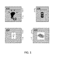
- Fig. 1 illustrates a system according to an exemplary embodiment of the invention.
- the system comprises a plurality of networked devices 100, 102, 104 and a configuration device 106.
- control relationships between the networked devices 100, 102, 104 are established by means of the configuration device 106, in that the configuration device 106 is used to identify the networked devices 100, 102, 104 by interacting with machine-readable tags, for example RFID tags, attached to them.
- at least one of the networked devices comprises a controller unit which is able to read identification data of other networked devices from its machine-readable tag. These identification data have been collected from the other networked devices by the configuration device 106, and subsequently written to the machine-readable tag by the same configuration device 106.
- the system is, for example, a Building Control System and the networked devices 100, 102, 104 are, for example, building control devices such as lighting elements, light switches, and light sensors.
- the configuration device 106 is a device capable of interacting with the machine-readable tags, for example an NFC-enabled smart phone.
- the method according to the invention establishes control relationships between two or more networked devices 100, 102, 104. For example, it makes a light switch and/or a light sensor control a lighting element.
- the networked devices 100, 102, 104 to be involved in the control relationship are identified by bringing the configuration device 106 in their close proximity in order to interact with their machine-readable tag. Further user interaction on the configuration device 106 may be required to establish control relationships between the thus identified networked devices 100, 102, 104.
- establishing control relationships is made intuitive by directly interacting with the networked devices 100, 102, 104, which reduces the installation effort and the probability of errors.
- the machine-readable tags are relatively cheap and do not have a large impact on the power budget of the networked devices 100, 102, 104.
- the cost of the configuration device 106 is not really an issue - a single configuration device may be used to install an abundance of networked devices - and therefore it can comprise a full-blown RFID reader, for example, but also rich user interaction means (user interface) which further simplifies the process of establishing control relationships.
- the networked devices 100, 102, 104 comprise a wireless network interface (e.g. Zigbee, Bluetooth, or Wi-Fi) to form a network together.
- a wireless network interface e.g. Zigbee, Bluetooth, or Wi-Fi
- a wired network interface e.g. Ethernet, DALI, or KNX
- the configuration device 106 does not need to be equipped with such a network interface, because the above-mentioned networked device which comprises the controller unit capable of reading identification data of other networked devices from its machine-readable tag, may take control of the establishment of the control relationship, for example by transmitting messages to the other networked devices via its network interface.
- the interaction between the configuration device 106 and the networked devices 100, 102, 104 takes place via short-range communication technology, for example RFID or NFC.
- short-range communication technology for example RFID or NFC.
- Any communication link that is enabled by bringing the configuration device 106 in close proximity of the networked devices 100, 102, 104 aligning both devices in some other way or even making a galvanic contact by "touching” the devices may provide an alternative.
- the actions of "touching”, “aligning” or “making contact” of the configuration device 106 device with the networked devices 100, 102, 104 signifies an explicit end-user intent to involve this particular networked device in establishing a control relationship.
- infrared communication or USB are alternatives.
- the configuration device 106 may also read a machine-readable optical tag, such as a barcode or QR-code sticker.
- a machine-readable optical tag such as a barcode or QR-code sticker.
- the configuration device 106 should comprise a compatible reader (e.g. a camera with barcode or QR-code recognition software).
- phase of establishing control relationships - or more general the phase of commissioning - is followed by a phase of normal operation during which these control relationships are used, for example, for enabling an end-user to operate the lights in a building.
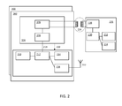
- Fig. 2 illustrates a first networked device 200, a second networked device 202 and a configuration 226 device according an exemplary embodiment of the invention.
- the second networked device 202 comprises an RFID tag 204, a host controller 212, a host memory 210, a (wireless) network interface 216 and device functions 214.
- the RFID tag 204 comprises a non-volatile memory 208 and an RFID interface 206, the latter enabling the configuration device 226 to contactlessly read the contents of the non-volatile memory 208 while being in close proximity of the second networked device 202.
- the host controller 212 is arranged to read or write the non-volatile memory 208 through a host connection 218 (wired interface, for example an I 2 C interface).
- An RFID tag with a host connection is called a "Connected Tag”.
- the RFID tag 204 is arranged to wake up the host controller 212 from an off- or very low-power state.
- the device functions 214 embody any of the primary functions provided by the components of the networked device, for example: sensing elements in a wireless sensor node, LEDs or fluorescent tubes and associated driver electronics in a lighting element or a breakable contact in a light switch.
- the configuration device 226 comprises an RFID interface 228 (for example an NFC device), a controller 230, a memory 232, and a user interface 234.
- the RFID interface 228 is capable of reading or writing the non-volatile memory of an RFID tag when brought into close proximity.
- the RFID interface 228 also supplies the necessary power to the RFID tag to accomplish this operation through magnetic induction, so effectively, the RFID interface 228 is a so-called RFID reader as defined in the RFID Handbook by Klaus Finkenzeller, 3rd edition, 2010, or an NFC device with the same capabilities.
- the user interface 234 is used to further select networked devices for establishing a control relationship according to the method of the invention and/or to confirm the establishment of this control relationship.
- the specifics of the user interface 234 depend on the way the user interaction is done. See “User interaction" below for different options.
- the user interface 234 could, for example, be implemented as a touch screen or a combination of buttons and indicator LEDs.
- all but one networked devices to be involved in the control relationship are first identified by the configuration device 226 reading identification data from each of their respective machine-readable tags.
- the configuration device 226 reading identification data from each of their respective machine-readable tags.
- only a single one of these networked devices is shown, i.e. the first networked device 200.
- some user interaction on the configuration device 226 is required to further select networked devices.
- the identification data of the thus far selected networked devices is written into the machine-readable tag of the last of the networked devices to be involved in the control relationship.
- This networked device is referred to as the second networked device 202.
- the host controller 212 of this second networked device 202 reads these identification data from its machine-readable tag 204 via a host connection 218 and uses them to establish the control relationship between the thus identified networked devices.
- the latter may involve transmitting messages into the network formed by the networked devices, which enables those devices to establish the control relationship.
- any particular networked device may act as a first networked device while establishing one control relationship and as a second networked device while establishing another control relationship, provided that the networked device has an RFID interface and a host connection.
- This increases the user-friendliness of the system, because the end-user may establish control relationships between a number of networked devices by performing an "NFC touch" on them in an arbitrary order.
- the configuration device 226 it is not necessary for the configuration device 226 to comprise a network interface. This is caused by the fact that the machine-readable tag 204 of the last touched networked device, i.e. the second networked device 202, is effectively used as a channel to transmit the desired control relationship into the network formed by the networked devices.
- the second networked device 202 administers the control relationship itself and/or transmits message(s) to have one or more other networked devices do this, depends again on the architecture of the Building Control System and the type of devices involved in the control relationship (including the type of the second networked device).
- Each networked device has a unique identifier which is stored in the RFID tag.
- the unique identifier of a particular networked device is typically used to address messages to that networked device either sooner or later. It is used sooner if the particular networked device administers a control relationship and a message has to be sent to it as part of step (4) of the above-described implemented method. It is used later if one or more other networked devices administer a control relationship and as part of that have stored the unique identifier of this particular networked device in their (non-volatile) memories.
- the unique identifier may be used during normal operation of the Building Control System to send control messages to the particular networked device (for example, a light switch, when actuated, sending an on/off/dim message to a lighting element that it has a control relationship with).
- the particular networked device for example, a light switch, when actuated, sending an on/off/dim message to a lighting element that it has a control relationship with.
- those unique identifiers are effectively network addresses as used in the network formed by the networked devices.
- this is not absolutely necessary.
- a message could be broadcast including the unique identifier of the intended recipients in its payload.
- networked devices receiving such a broadcast message must first inspect the payload to verify whether they are indeed an intended recipient.
- the unique identifier could, for example, be:
- a unique identifier that is not a network address - example (a) above - requires broadcast messages with the unique identifier in their payload.
- a networked device has a globally unique MAC-address - example (b) - which typically is not directly used for routing in the network.
- - example (c) - a dynamic network address, for example a dynamic IP-address as assigned by a DHCP-server, is used for actual routing in the network.
- Dynamic addresses have an advantage when routing in large, multi-hop, heterogeneous networks such as the Internet. This implies that it may be advantageous if the unique identifier is a network address and in particular if it is a dynamic network address.
- the host controller - and/or the networked device's (wireless) network interface - and the RFID tag must know the unique identifier.
- the RFID tags of the networked devices are so-called "Connected Tag", i.e. if they have a (wired) connection with the controller units of the respective networked devices, this is relatively straightforward.
- the second networked device 202 has such a host connection 218, whereas the other networked devices (the plurality of first networked devices 200) may or may not have such a host connection 218.
- the first networked device 200 may also have a machine-readable tag which is not based on RFID technology, such as a barcode element or QR-code element, provided that the configuration device 226 is capable of reading such a tag.
- Different types of networked devices will be present in the Building Control System, for example light switches, light sensors, and lighting elements.
- the types of the networked devices involved in a control relationship determine the semantics of that control relationship. For example, establishing a control relationship between a light switch and a lighting element means that the actuation of the light switch will control the lighting element.
- the knowledge of these semantics i.e. the so-called "domain model" is somehow embedded in the system.
- the program code stored in the host memory of a light switch - and executed by its host controller - contains instructions pertaining to its role in the control relationship
- the program code stored in the host memory of a lighting element - and executed by its host controller - contains instructions pertaining to its role in the control relationship, which is a different role.
- these semantics may determine which networked device(s) will administer the established control relationship (see "Administering the established control relationship" below) and therefore which networked devices need to receive a message in step (4) of the above-described implemented method.
- step (1) of the above-described implemented method this information may play a role in determining which networked devices to transmit a message to.
- sensors e.g. light switches, light sensors, temperature sensors
- actuators e.g. lighting elements, ventilators, heaters
- controller devices i.e. centralized or decentralized devices whose main purpose is to serve as a kind of intermediate between sensors and actuators.
- administering control relationships may be done by different classes of devices and therefore that the above-described implemented method may have to consider carefully, in step (4), which networked devices to transmit a message to.
- the device class may be derived from the device type as stored in the RFID tag.
- a "class” e.g. sensor
- a type e.g. light sensor
- step (2) of the above-described implemented method it is mentioned that the end-user optionally interacts with the configuration device to further select and/or deselect networked devices.
- the configuration device may support a combination of different ways of user interaction.
- the configuration device comprises a touch screen (or another combination of a graphical display and a pointing device).
- the configuration device could, for example, be an NFC-enabled smart phone or a web tablet.
- the screen will display a plurality of graphical representations - icons - of networked devices. Touching a particular first networked device with the configuration device, in accordance with step (1) of the above-described implemented method, will cause an icon representing that particular network device to (re)appear on the screen. Also it may be selected by default for subsequent inclusion in the control relationship.
- the user interface may provide for means to search for networked devices present in the Building Control System that may - or may not - have been previously touched by this particular configuration device.
- Search parameters may include the type or class of the networked device, the location (e.g. room) of the networked device or networked devices that do not participate in a control relationship yet.
- the result of a search action will again comprise icons representing networked devices that can be used to establish control relationships by first selecting them.
- the first networked devices to be included or excluded in the control relationship are selected or deselected via a graphical user interface.
- the second network device is, by definition, always included in the control relationship, and therefore it does not need to be selected explicitly via the user interface.
- only the icons corresponding to the plurality of first networked devices to be involved in the control relationship need to be selected.
- the second networked device is selected by "NFC touch" of the physical device itself. This action also doubles as confirmation.
- a simple case is establishing a control relationship between only two networked devices. In this case, the icon corresponding to the first networked device is selected on the touch screen and the second networked device is touched physically by means of NFC.
- the last touched networked device is in fact the second networked device. For example, this is necessary when all devices in the network can act as a first networked device or a second networked device, i.e. when they comprise a Connected Tag and when it should be possible to configure them in an arbitrary order. In this case, it is sufficient to press a confirmation button (graphical or physical) before performing the last touch.
- a special case of what is described above under "Touch screen for further selection and de-selection of first networked devices" is to automatically select the previously touched networked device. In other words, simply establish a control relationship between the two most recently touched networked devices.
- This configuration device may be very cost effective and, for example, have the form-factor of a pen (installation pen). As such it may be supplied together with a networked device for building automation, such as for example a home gateway.
- the home gateway may comprise a cavity to store the installation pen.
- the home gateway may provide means to charge the battery of the installation pen while it is stored in the cavity.
- a number of commissioning operations related to establishing a control relationship are: de-establishing a control relationship, grouping and copying control relationships.
- commissioning operations may be supported by the system and method according to the invention, for example, as described below.
- step (4) of the above-described implemented method the messages sent must now cause their recipients to de-administer, rather than administer control relationships. This can be accomplished by distinguishing different types of messages (e.g. "administer” vs. "de-administer” messages).
- Grouping is a notion applied to networked devices of a similar type. For example, a group comprising lighting elements could be created. Subsequently, this group could be used as a single entity in establishing control relationships. For example, a lighting switch can be made to control a group of lighting elements; actuating the light switch causes all the lighting elements to switch on or switch off simultaneously.
- Establishing groups can be very similar to establishing control relationships, but clearly the semantics are different. As a matter of fact, the types or classes of the respective networked devices involved may determine whether a grouping or a control relationship is being established.
- a grouping could be administered by all of the networked devices comprised in the group. Assume furthermore that also a control relationship has been accomplished between a member of that group (e.g. lighting element) and another networked device (e.g. lighting switch). When, for example, the lighting switch sends an on/off/dim message to the member of the group (i.e. lighting element) that it has a control relationship with, that group member will forward this message to the other lighting elements comprised in the group.
- a member of that group e.g. lighting element
- another networked device e.g. lighting switch
- a grouping could be administered by a controller device, the controller device functioning as a proxy.
- a lighting switch having a control relationship established with a group of lighting elements will send an on/off/dim message to the controller device and the controller device will forward this message to each of the lighting elements comprised in the group.
- the group is essentially a virtual device and the proxy will typically support a plurality of such groups or virtual devices.
- the RFID tag of the proxy cannot be used to unambiguously establish control relationships with the group.
- a dedicated RFID tag e.g. a so-called NFC-sticker
- NFC-sticker can be written to as part of the grouping procedure. For example, all lighting elements in a room can be "represented" by an NFC-sticker located next to the door.
- a networked device may have the same control relationships as another networked device. For example, a first lighting switch controlling all lighting elements in a room is located near a first door of that room. Now a second lighting switch is installed near a second door of the same room and also needs to control all lighting elements. Rather than establishing these control relationships one-by-one again, the end-user would simply like to "clone” the control relationships from the first lighting switch into the second lighting switch. This can also be accomplished with an NFC touch. For example, when the configuration device is an installation pen, it can be accomplished by setting the installation pen in a dedicated "clone" mode by means of a special mode switch. While set to this "clone" mode the end-user first touches the first lighting switch with the installation pen and subsequently touches the second lighting switch with the installation pen.
- Copying control relationships may be realized in different ways depending on, amongst others, where the control relationships are administered in the system (see "Administering the established control relationship"). As an example, it is assumed that the networked devices involved in the copying administer all the control relationships they are involved in (or at least the subset thereof that needs to be copied). In this case, the control relationships of the first networked device - i.e. the set of networked devices that the first networked device has a control relationship with - should be retrieved from the first networked device and provided to the second networked device through intervention of the configuration device.
- the configuration device reads the control relationships from the RFID tag of the first networked device upon "touch” and writes them into the RFID tag of the second networked device upon subsequent "touch”. Subsequently, the host controller of the second networked device reads those control relationships from the RFID tag through the host connection and administers them (or simply leaves them in the RFID tag, in case networked devices maintain their administration of control relationships in their respective RFID tags). In case the first networked device does not administer all its control relationships, it may query the network or a central server/registry for data relating to these control relationships, and subsequently provide those data to the configuration device.
- Some networked devices may be in an off - or very low-power - state for most of the time.
- a wireless sensor node has very little energy at its disposal. It is powered by an energy harvester or a small primary battery and has to provide for years or even decades of unattended operation.
- As its only duty is to measure certain physical parameters (e.g. temperature, ambient light and/or specific gas concentrations) periodically (e.g. once every 1-15 minutes), it wakes up every period for a brief amount of time (e.g. 10 milliseconds), just long enough to do its measurements and transmit a message into the network. For the rest of the period it is fast asleep and not able to receive any messages.
- a similar example is a light switch, powered by a small battery or a mechanical harvester, that only wakes up and transmits a short message when pressed. For the rest of the time it also is fast asleep and unable to receive messages.
- the wake-up signal 220 is provided from the RFID tag 204 to the host controller 212 of the second networked device 202.
- an RFID device 228 for example an NFC device
- the wake-up signal 220 is raised and the second networked device 202 is woken up from its off - or very low power - state (i.e. it is switched on).
- the wake-up signal 220 is raised when the appearance - or the subsequent disappearance - of a field generated by an RFID device 228, is detected. In another variant the wake-up signal 220 is raised only when that RFID device 228 addresses this particular RFID tag 204. In yet another variant the wake-up signal 220 is only raised when the memory 208 - or predetermined memory cells thereof - have been written to or read from (or both) during the interaction. In other words, the raising of the wake-up signal 220 may be a more or less specific indication of an event on the RFID connection 224 (e.g. merely an RFID field applied/removed vs. a specific memory cell read/written).
- Fig. 2 suggests that the wake-up signal 220 is fed to a pin of the host controller 212 causing it to wake up from an off - or actually very low-power - state.
- the power supply of the second networked device 202 is disabled or disconnected in the inactive state and the wake-up signal 220 pulls a switch, e.g. galvanic or MOSFET, to power the second networked device 202 to cause it to move to the active state.
- a switch e.g. galvanic or MOSFET
- the use of a wake-up signal 220 from the RFID tag may also be beneficial if the second networked device 202 is not switched off (or in a very low-power state). In this case, the wake-up signal 220 simply serves as an interrupt signal to the host controller 212, triggering it to start executing the next step of the method according to the invention.
- the last one of the networked devices gets a message written into its RFID tag 204.
- the host controller 212 may be woken up by means of the wake-up signal 220 and take action, specifically, administer the control relationship and/or transmit one or more messages (see step (4) of the above-described implemented method).
- the second networked device 202 has to transmit messages to other networked devices in order for them to administer the control relationship there may be a desire for this action to take place substantially instantaneously.
- the control relationship is administered by the sensors (including switches) in the network. See the section "Administering the established control relationship" above. They should remember the unique identifiers (e.g. addresses) of other networked devices, specifically actuators such as lighting elements or HVAC equipment. During normal operation they will use these unique identifiers / addresses to transmit messages specifically to those other networked devices.
- unique identifiers e.g. addresses
- other networked devices specifically actuators such as lighting elements or HVAC equipment.
- these networked devices In order to receive messages these networked devices first need to be woken up. As an optional feature of the invention, it is proposed to wake up these networked devices (i.e. the plurality of first networked devices 200) by means of a wake-up signal, as soon as (the unique identifier stored in) their RFID tags are read by the configuration device 226. After receipt of the message, it administers the control relationship and goes back to sleep.
- the first networked device 200 still may be awake for an extended period of time. There may be a considerable amount of time in between the moment that the RFID tag of the first networked device 200 is read in step (1) and the moment that the end-user confirms the establishment of the control relationship in step (3) of the above-described implemented method, which triggers the transmission of the message that the first networked device 200 is waiting for.
- this amount of time may be unbounded as the end-user may break off the procedure of establishing the control relationship halfway through.
- a time-out may be used (e.g. five minutes). If a message is not received within this time-out period, counting from the moment of reading the RFID tag of the first networked device 200 by the configuration device 226, the first networked device 200 goes back to sleep.
- the wake-up signal may still be used to bring the networked device from a state where it is not able to receive any messages to a state where it wakes up at predetermined moments to check/wait for a message.
- both the first and the second networked device are commissionable while they are not powered (or otherwise not yet reachable over the network).
- the end-user is able to touch them with an NFC-enabled phone, for example, while they are not powered, and still the intended control relationship is established.
- a retrofit light bulb with a wireless network interface embedded in its base can be made part of a control relationship before it is screwed in the socket. Once in the socket it may be too impractical to access with the configuration device.
- control relationships can also be established before the network connecting the devices is operational. See also the section "First touch: combination with network joining and/or localization” below. Networked devices can be commissioned randomly and only somewhere along the way the network gradually becomes operational. It is not necessary to first build up a functional network, before being able to establish control relationships.
- Powerless commissioning can be achieved in various ways, as explained below.
- the second networked device may be arranged to check whether the identification data has been written into its corresponding tag after it powers up, and if so, to send messages to all concerned (for example a broadcast message to all first networked devices to be included in the control relationship, a specific message to first networked devices with certain types or a message to a central registry).
- all concerned for example a broadcast message to all first networked devices to be included in the control relationship, a specific message to first networked devices with certain types or a message to a central registry.
- the second networked device checks whether the identification data has been written into its corresponding tag and, if so, it uses the identification data to establish the control relationship.
- the first networked device powerless commissioning can be achieved in various ways, for example:
- the configuration device may set a flag (i.e. write a predetermined value, e.g. "1", into a predetermined memory location) in the RFID tag of the first networked device during the same end-user "touch" operation when it reads the unique identifier from that RFID tag.
- This flag can subsequently be used by the first networked device upon power-up to determine whether it needs to check for new setup messages (i.e. messages intended for establishing control relationships).
- the first networked device should also clear the flag.
- this may only be done if the optional type information in the RFID tag of the first networked device indicates that this first networked device is indeed to be involved in administering the control relationship.
- a contact address may be written into the RFID tag of the first networked device.
- the first networked device may use this contact address to obtain further information about the to be established control relationships, in particular, to query a device identified by said contact data for the presence of a setup message.
- the contact address may be the address of the registry mentioned above. Notice, that upon the first device contacting the registry, that registry may not yet be aware of the control relationship (either because the second networked device hasn't been "touched" yet, or because the second device hasn't powered up yet). In this case, the registry may remember the request of the first networked device for further information and reply as soon as it becomes aware of the control relationship.
- the flag and/or the contact address may be accompanied by a (unique) identifier identifying the (to be established) control relationship itself (this unique identifier may be generated by the configuration device).
- This control relationship identifier may help the registry in identifying the specific control relationship that first and/or second networked device are communicating about. This may be relevant when multiple control relationships involving a particular first and/or second networked device are established when the respective device is not powered. It is noted that in that case also multiple messages, flags and/or contact addresses must be stored in the respective RFID tags. In other words, data for a control relationship which is still being established should not be overwritten.
- the first networked device comprises a Connected Tag (i.e. the first machine readable tag must be an RFID tag with a wired host connection).
- network joining needs to be performed before control relationships can be established. This is obvious from the fact that messages need to be sent through the network to administer control relationships and also that, in some embodiments, a dynamic network address - being an end-result of network joining - is used as the unique identifier.
- network joining is also an operation that can advantageously be performed by NFC-based "touching" with a portable configuration device.
- a further advantage i.e. more Ease-of-Install
- a single NFC "touch" is used to both join a device into a network and identify it for establishing a control relationship.
- some latency may be involved, i.e. the end-user may have to keep the portable configuration device in close proximity of the networked device (that is to be joined and identified) for a longer period of time.
- Audio-visual feedback e.g. a beep sounding, a LED blinking or a message on a display
- step (1) of the above-described implemented method has to be adapted.
- a validation step is performed to determine whether it is already part of the network. If a device it not part of the network, network joining is performed in addition to identification.
- the RFID tag is a Connected Tag
- the host controller could set a flag in the non-volatile memory indicating that the networked device is indeed part of the network. In case the unique identifier is a dynamic network address, the presence of a valid dynamic network address could be interpreted as such a flag.
- the RFID tag When the RFID tag is not a Connected Tag (i.e. a host connection is not provided) some message exchange is required to perform the validation. This message exchange may be the same message exchange that is used to accomplish network joining. If the networked device receiving a network joining request is already part of the network it will simply reply this fact (or just "successfully joined") to the portable configuration device. Again some latency may be involved, necessitating proper audio-visual feedback to the end-user.
- the operation of localizing a networked device may be combined in a single "touch" with identifying the networked device for establishing a control relationship according to the present invention. Or even, the three actions of network joining, localization, and identification for establishing a control relationship may be combined in a single "touch".
- the procedure of establishing control relationships should be secure, meaning that unauthorized people should not be able to perform this procedure with just an arbitrary NFC-enabled mobile phone, for example. Otherwise unauthorized people might gain control over, for example, lighting, HVAC or even security or safety related functions in a building, which is not desirable.
- the networked devices - and hence the RFID tags attached to them - are accessible to whoever has access to the building. Therefore, if a building is accessible to the general public, the general public is also able to read or write these RFID tags.
- the RFID tag (i.e. Connected Tag) of the second networked device is effectively used as a communication gateway for transmitting messages into the network formed by the networked devices.
- the communication link between the RFID interface/device of the (authorized) portable configuration device and the RFID tag of the second networked device must be secured as well. This can, for example, be easily accomplished by regarding this communication link as an extension of the network formed by the networked devices. This means that the (authorized) portable configuration device should obtain the credentials of that network as part of becoming an authorized portable configuration device.
- the portable configuration device is also used for network joining as proposed in the section "First touch: combination with network joining and/or localization" above, it already has knowledge of those credentials because it is used to pass them on to other networked devices. Alternatively, the RFID tags of the already commissioned devices could be locked.
- any reference sign placed between parentheses shall not be construed as limiting the claim.
- the word “comprise(s)” or “comprising” does not exclude the presence of elements or steps other than those listed in a claim.
- the word “a” or “an” preceding an element does not exclude the presence of a plurality of such elements.
- the invention may be implemented by means of hardware comprising several distinct elements and/or by means of a suitably programmed processor. In a device claim enumerating several means, several of these means may be embodied by one and the same item of hardware.
- the mere fact that certain measures are recited in mutually different dependent claims does not indicate that a combination of these measures cannot be used to advantage.
Landscapes
- Engineering & Computer Science (AREA)
- Automation & Control Theory (AREA)
- Computer Networks & Wireless Communication (AREA)
- Signal Processing (AREA)
- General Physics & Mathematics (AREA)
- General Engineering & Computer Science (AREA)
- Physics & Mathematics (AREA)
- Multimedia (AREA)
- General Business, Economics & Management (AREA)
- Business, Economics & Management (AREA)
- Mobile Radio Communication Systems (AREA)
- Small-Scale Networks (AREA)
- Selective Calling Equipment (AREA)
Priority Applications (3)
| Application Number | Priority Date | Filing Date | Title |
|---|---|---|---|
| EP12182670.5A EP2704365B1 (de) | 2012-08-31 | 2012-08-31 | Verfahren zur Herstellung von Steuerbeziehungen, Konfigurationsvorrichtung, vernetzte Vorrichtung und Computerprogramm |
| CN201310344173.0A CN103676821B (zh) | 2012-08-31 | 2013-08-08 | 建立控制关系的方法,配置设备和联网设备 |
| US14/015,132 US9774637B2 (en) | 2012-08-31 | 2013-08-30 | Method of establishing control relationships, configuration device, networked device and computer program product |
Applications Claiming Priority (1)
| Application Number | Priority Date | Filing Date | Title |
|---|---|---|---|
| EP12182670.5A EP2704365B1 (de) | 2012-08-31 | 2012-08-31 | Verfahren zur Herstellung von Steuerbeziehungen, Konfigurationsvorrichtung, vernetzte Vorrichtung und Computerprogramm |
Publications (2)
| Publication Number | Publication Date |
|---|---|
| EP2704365A1 true EP2704365A1 (de) | 2014-03-05 |
| EP2704365B1 EP2704365B1 (de) | 2016-02-03 |
Family
ID=46801344
Family Applications (1)
| Application Number | Title | Priority Date | Filing Date |
|---|---|---|---|
| EP12182670.5A Active EP2704365B1 (de) | 2012-08-31 | 2012-08-31 | Verfahren zur Herstellung von Steuerbeziehungen, Konfigurationsvorrichtung, vernetzte Vorrichtung und Computerprogramm |
Country Status (3)
| Country | Link |
|---|---|
| US (1) | US9774637B2 (de) |
| EP (1) | EP2704365B1 (de) |
| CN (1) | CN103676821B (de) |
Cited By (7)
| Publication number | Priority date | Publication date | Assignee | Title |
|---|---|---|---|---|
| EP2991279A1 (de) * | 2014-08-27 | 2016-03-02 | HAGER CONTROLS (Société par Actions Simplifiée) | Verfahren zum bidirektionalen informationstransfer von einem heimsystem aus, ein solches system und eine passende anordnung zur umsetzung eines solchen verfahrens |
| US9326345B2 (en) | 2013-02-26 | 2016-04-26 | Nxp B.V. | Lighting control method, computer program product and lighting control system |
| FR3027696A1 (fr) * | 2014-10-27 | 2016-04-29 | Hager Controls | Procede d'appairage indirect et/ou de parametrage indirect et/ou de diagnostic indirect, systeme et assemblage domotiques convenant a la mise en œuvre d'un tel procede |
| CN106549861A (zh) * | 2015-09-23 | 2017-03-29 | 上海晶唐智能科技有限公司 | 一种多功能智能网关 |
| WO2017215955A1 (de) * | 2016-06-13 | 2017-12-21 | Zumtobel Lighting Gmbh | Adresszuweisung und konfigurierung von komponenten eines beleuchtungssystems mittels transponder |
| EP3293588A1 (de) * | 2016-09-08 | 2018-03-14 | Siemens Schweiz AG | Verfahren zur provisionierung von raumautomationskomponenten eines gebäudeautomationssystems |
| CN109683944A (zh) * | 2018-11-16 | 2019-04-26 | 平安科技(深圳)有限公司 | 应用功能开关管理方法、装置、设备及可读存储介质 |
Families Citing this family (15)
| Publication number | Priority date | Publication date | Assignee | Title |
|---|---|---|---|---|
| EP2573948B1 (de) | 2011-09-23 | 2017-03-15 | Nxp B.V. | System und Verfahren zur Inbetriebnahme von Geräten |
| EP2624081B1 (de) | 2012-01-31 | 2018-01-10 | Nxp B.V. | Konfigurationsverfahren, Konfigurationsvorrichtung, Computerprogrammprodukt und Steuerungssystem |
| EP2665235B1 (de) | 2012-05-15 | 2016-01-06 | Nxp B.V. | Verfahren zum Aufbauen einer sicheren Kommunikation zwischen Knoten in einem Netzwerk, Netzwerkknoten, Key Manager, Installationsvorrichtung und Computerprogrammprodukt |
| US20150277407A1 (en) * | 2014-03-27 | 2015-10-01 | Trane International Inc. | Location detection of control equipment in a building |
| US10291292B2 (en) | 2014-09-02 | 2019-05-14 | Johnson Controls Technology Company | Wireless sensor with near field communication circuit |
| US9732977B2 (en) | 2014-09-02 | 2017-08-15 | Johnson Controls Technology Company | Systems and methods for configuring and communicating with HVAC devices |
| EP3059919A1 (de) | 2015-02-19 | 2016-08-24 | Nxp B.V. | Verfahren und system zur ermöglichung von netzwerkverbindung |
| EP3086585B1 (de) | 2015-04-23 | 2019-12-11 | Nxp B.V. | Verfahren und system zur sicherung von in einem netzwerk kommunizierten daten |
| US9641553B2 (en) * | 2015-09-25 | 2017-05-02 | Intel Corporation | Methods and apparatus to facilitate end-user defined policy management |
| CN105301977A (zh) * | 2015-11-11 | 2016-02-03 | 小米科技有限责任公司 | 基于智能设备的电子音乐实现方法及装置 |
| CN106054825B (zh) * | 2016-04-27 | 2024-08-20 | 杭州鸿雁电器有限公司 | 便携式控制装置 |
| DE102017103553B4 (de) * | 2017-02-21 | 2022-10-13 | Phoenix Contact Gmbh & Co. Kg | Verfahren zur Konfiguration und/oder Parametrierung einer Steuerungseinrichtung sowie ein Verfahren zum Erstellen eines digitalen Verdrahtungsprotokolls für ein Automatisierungssystem |
| ES2922322T3 (es) | 2020-02-25 | 2022-09-13 | Siemens Schweiz Ag | Configuración de dispositivo |
| CN112163125A (zh) * | 2020-09-22 | 2021-01-01 | 海尔优家智能科技(北京)有限公司 | 设备管理方法和装置、存储介质及电子设备 |
| US12015277B2 (en) | 2022-07-25 | 2024-06-18 | Nxp B.V. | Sensor node with wireless energy harvesting and method for operating the sensor node |
Citations (3)
| Publication number | Priority date | Publication date | Assignee | Title |
|---|---|---|---|---|
| WO2006016845A1 (en) * | 2004-08-10 | 2006-02-16 | Tac Ab | Field device management |
| WO2009128001A2 (en) | 2008-04-18 | 2009-10-22 | Philips Intellectual Property & Standards Gmbh | Method of commissioning a device arrangement |
| WO2010032227A1 (en) | 2008-09-22 | 2010-03-25 | Nxp B.V. | Automatic address selection for controllable devices |
Family Cites Families (24)
| Publication number | Priority date | Publication date | Assignee | Title |
|---|---|---|---|---|
| EP0513443B1 (de) * | 1991-05-06 | 1999-11-17 | Koninklijke Philips Electronics N.V. | Gebäudeleitsystem |
| US5519878A (en) | 1992-03-18 | 1996-05-21 | Echelon Corporation | System for installing and configuring (grouping and node address assignment) household devices in an automated environment |
| EP1546477A4 (de) | 2002-09-04 | 2008-12-17 | Miller Herman Inc | Raumaufteilungssystem mit technologie |
| US7250695B2 (en) * | 2003-10-31 | 2007-07-31 | Hewlett-Packard Development Company, L.P. | Controlling power supplied to a circuit using an externally applied magnetic field |
| JP4337645B2 (ja) * | 2004-06-17 | 2009-09-30 | セイコーエプソン株式会社 | Icタグモジュール、電子機器、情報通信システムおよびicタグモジュールの通信制御方法 |
| US20080190043A1 (en) | 2004-08-31 | 2008-08-14 | Waltraud Beckmann | Space Division System with Material Support Linkage |
| EP1812843A4 (de) | 2004-08-31 | 2014-08-27 | Miller Herman Inc | Auf designation basierende protokollsysteme zum umkonfigurieren von steuerbeziehungen zwischen einrichtungen |
| US9820658B2 (en) * | 2006-06-30 | 2017-11-21 | Bao Q. Tran | Systems and methods for providing interoperability among healthcare devices |
| US20060061482A1 (en) * | 2004-09-23 | 2006-03-23 | Patrick Monney | RFID auto-connect for wireless devices |
| CN101228812B (zh) | 2005-03-12 | 2011-06-15 | 路创电子公司 | 用于照明控制系统的手提式程序控制器 |
| CN101554091B (zh) * | 2006-11-17 | 2017-02-08 | 皇家飞利浦电子股份有限公司 | 用于照明控制的光棒 |
| US9872365B2 (en) | 2006-12-06 | 2018-01-16 | Philips Lighting Holding B.V. | Method and apparatus for replacing a device in a network |
| US8466790B2 (en) * | 2007-07-20 | 2013-06-18 | Nokia Corporation | Information sharing in a smart space |
| MX2011002358A (es) | 2008-09-03 | 2011-09-27 | Siemens Industry Inc | Sistema inalambrico de administracion de construcciones y metodos de administracion para una construccion. |
| US8981913B2 (en) | 2010-02-18 | 2015-03-17 | Redwood Systems, Inc. | Commissioning lighting systems |
| US8381981B2 (en) * | 2010-05-03 | 2013-02-26 | Redwood Systems, Inc. | Radio frequency identification of lighting fixtures |
| CN102243488A (zh) * | 2010-05-11 | 2011-11-16 | 上海泰昌健身器材有限公司 | 一种远程控制集成接入设备的控制方法 |
| US8598978B2 (en) * | 2010-09-02 | 2013-12-03 | Lutron Electronics Co., Inc. | Method of configuring a two-way wireless load control system having one-way wireless remote control devices |
| EP2573948B1 (de) | 2011-09-23 | 2017-03-15 | Nxp B.V. | System und Verfahren zur Inbetriebnahme von Geräten |
| EP2602677B1 (de) | 2011-12-05 | 2018-02-21 | Nxp B.V. | Lokalisierungsverfahren, Computerprogrammprodukt und Lokalisierungsvorrichtung |
| EP2624081B1 (de) | 2012-01-31 | 2018-01-10 | Nxp B.V. | Konfigurationsverfahren, Konfigurationsvorrichtung, Computerprogrammprodukt und Steuerungssystem |
| EP2626755B1 (de) | 2012-02-10 | 2019-04-10 | Nxp B.V. | Kalibrierungsverfahren, Kalibrierungsvorrichtung und Messvorrichtung |
| EP2650820B1 (de) | 2012-04-12 | 2014-10-08 | Nxp B.V. | Steuerverfahren und Computerprogrammprodukt |
| EP2665235B1 (de) | 2012-05-15 | 2016-01-06 | Nxp B.V. | Verfahren zum Aufbauen einer sicheren Kommunikation zwischen Knoten in einem Netzwerk, Netzwerkknoten, Key Manager, Installationsvorrichtung und Computerprogrammprodukt |
-
2012
- 2012-08-31 EP EP12182670.5A patent/EP2704365B1/de active Active
-
2013
- 2013-08-08 CN CN201310344173.0A patent/CN103676821B/zh active Active
- 2013-08-30 US US14/015,132 patent/US9774637B2/en active Active
Patent Citations (3)
| Publication number | Priority date | Publication date | Assignee | Title |
|---|---|---|---|---|
| WO2006016845A1 (en) * | 2004-08-10 | 2006-02-16 | Tac Ab | Field device management |
| WO2009128001A2 (en) | 2008-04-18 | 2009-10-22 | Philips Intellectual Property & Standards Gmbh | Method of commissioning a device arrangement |
| WO2010032227A1 (en) | 2008-09-22 | 2010-03-25 | Nxp B.V. | Automatic address selection for controllable devices |
Cited By (12)
| Publication number | Priority date | Publication date | Assignee | Title |
|---|---|---|---|---|
| US9326345B2 (en) | 2013-02-26 | 2016-04-26 | Nxp B.V. | Lighting control method, computer program product and lighting control system |
| EP2991279A1 (de) * | 2014-08-27 | 2016-03-02 | HAGER CONTROLS (Société par Actions Simplifiée) | Verfahren zum bidirektionalen informationstransfer von einem heimsystem aus, ein solches system und eine passende anordnung zur umsetzung eines solchen verfahrens |
| FR3025343A1 (fr) * | 2014-08-27 | 2016-03-04 | Hager Controls | Procede de transfert d'information bidirectionnel a partir d'un systeme domotique, un tel systeme et un ensemble convenant a la mise en œuvre du procede |
| FR3027696A1 (fr) * | 2014-10-27 | 2016-04-29 | Hager Controls | Procede d'appairage indirect et/ou de parametrage indirect et/ou de diagnostic indirect, systeme et assemblage domotiques convenant a la mise en œuvre d'un tel procede |
| EP3016320A1 (de) * | 2014-10-27 | 2016-05-04 | HAGER CONTROLS (Société par Actions Simplifiée) | Indirektes pairing- und/oder parametrisierungsverfahren und/oder indirektes diagnoseverfahren, haustechnisches system und bauteil, das für die umsetzung eines solchen verfahrens ausgelegt ist |
| CN106549861A (zh) * | 2015-09-23 | 2017-03-29 | 上海晶唐智能科技有限公司 | 一种多功能智能网关 |
| WO2017215955A1 (de) * | 2016-06-13 | 2017-12-21 | Zumtobel Lighting Gmbh | Adresszuweisung und konfigurierung von komponenten eines beleuchtungssystems mittels transponder |
| AT16637U1 (de) * | 2016-06-13 | 2020-03-15 | Zumtobel Lighting Gmbh | Adresszuweisung und Konfigurierung von Komponenten eines Beleuchtungssystems mittels Transponder |
| EP3293588A1 (de) * | 2016-09-08 | 2018-03-14 | Siemens Schweiz AG | Verfahren zur provisionierung von raumautomationskomponenten eines gebäudeautomationssystems |
| US10171262B2 (en) | 2016-09-08 | 2019-01-01 | Siemens Schweiz Ag | Method for provisioning of room automation components of a building automation |
| CN109683944A (zh) * | 2018-11-16 | 2019-04-26 | 平安科技(深圳)有限公司 | 应用功能开关管理方法、装置、设备及可读存储介质 |
| CN109683944B (zh) * | 2018-11-16 | 2024-05-07 | 平安科技(深圳)有限公司 | 应用功能开关管理方法、装置、设备及可读存储介质 |
Also Published As
| Publication number | Publication date |
|---|---|
| CN103676821A (zh) | 2014-03-26 |
| EP2704365B1 (de) | 2016-02-03 |
| US9774637B2 (en) | 2017-09-26 |
| CN103676821B (zh) | 2016-08-10 |
| US20140068089A1 (en) | 2014-03-06 |
Similar Documents
| Publication | Publication Date | Title |
|---|---|---|
| US9774637B2 (en) | Method of establishing control relationships, configuration device, networked device and computer program product | |
| US10791193B2 (en) | Remote access gateway configurable control system | |
| EP2573948B1 (de) | System und Verfahren zur Inbetriebnahme von Geräten | |
| US9992037B2 (en) | Method for automatically mapping smart plug and electronic device connected thereto in home gateway and device therefor | |
| WO2019222056A1 (en) | Bluetooth mesh network provisioning | |
| US8755913B2 (en) | Lighting control network | |
| CN106063380A (zh) | 用于可寻址照明的基于平板的调试工具 | |
| CN107534941B (zh) | 用于网络上的通信的系统 | |
| TW201145946A (en) | Wireless network system with enhanced address conflict resolving functionality | |
| CN109413515A (zh) | 设备控制方法、装置、移动终端及服务器 | |
| CN104865835A (zh) | 一种基于ZigBee的智能家居系统 | |
| US20140129041A1 (en) | System and method for controlling at least one device | |
| US11294341B2 (en) | Controlled appliance and method for interacting with a remote control device via the BLE standard | |
| JP4931659B2 (ja) | 家電ネットワークシステム | |
| US11837081B2 (en) | Remote control device and method for interacting with a controlled appliance via the BLE standard | |
| CA3044651A1 (en) | Environment control system for controlling environmental conditions in a building | |
| TW200934175A (en) | Wireless network system with sensing, monitoring and managing functions | |
| EP2866384A1 (de) | Datenkommunikationssystem sowie entsprechende Verfahren | |
| Lee et al. | A smart energy system with distributed access control | |
| AU2022100049A4 (en) | A system for configuring a control device of a mesh network of connected devices | |
| US11089545B1 (en) | System and method for low power data transmission and control | |
| EP3542599B1 (de) | Inbetriebnahme einer oder mehreren vorrichtungen eines beleuchtungssystems | |
| CN108141396A (zh) | 家庭自动化系统设备功率优化 | |
| RU2574832C2 (ru) | Беспроводная сетевая система с улучшенными функциональными возможностями разрешения конфликтов адресов |
Legal Events
| Date | Code | Title | Description |
|---|---|---|---|
| 17P | Request for examination filed |
Effective date: 20131031 |
|
| AK | Designated contracting states |
Kind code of ref document: A1 Designated state(s): AL AT BE BG CH CY CZ DE DK EE ES FI FR GB GR HR HU IE IS IT LI LT LU LV MC MK MT NL NO PL PT RO RS SE SI SK SM TR |
|
| AX | Request for extension of the european patent |
Extension state: BA ME |
|
| PUAI | Public reference made under article 153(3) epc to a published international application that has entered the european phase |
Free format text: ORIGINAL CODE: 0009012 |
|
| 17Q | First examination report despatched |
Effective date: 20140321 |
|
| RBV | Designated contracting states (corrected) |
Designated state(s): AL AT BE BG CH CY CZ DE DK EE ES FI FR GB GR HR HU IE IS IT LI LT LU LV MC MK MT NL NO PL PT RO RS SE SI SK SM TR |
|
| GRAP | Despatch of communication of intention to grant a patent |
Free format text: ORIGINAL CODE: EPIDOSNIGR1 |
|
| INTG | Intention to grant announced |
Effective date: 20150907 |
|
| GRAS | Grant fee paid |
Free format text: ORIGINAL CODE: EPIDOSNIGR3 |
|
| INTG | Intention to grant announced |
Effective date: 20151119 |
|
| GRAA | (expected) grant |
Free format text: ORIGINAL CODE: 0009210 |
|
| AK | Designated contracting states |
Kind code of ref document: B1 Designated state(s): AL AT BE BG CH CY CZ DE DK EE ES FI FR GB GR HR HU IE IS IT LI LT LU LV MC MK MT NL NO PL PT RO RS SE SI SK SM TR |
|
| REG | Reference to a national code |
Ref country code: GB Ref legal event code: FG4D |
|
| REG | Reference to a national code |
Ref country code: AT Ref legal event code: REF Ref document number: 774111 Country of ref document: AT Kind code of ref document: T Effective date: 20160215 Ref country code: CH Ref legal event code: EP |
|
| REG | Reference to a national code |
Ref country code: IE Ref legal event code: FG4D |
|
| REG | Reference to a national code |
Ref country code: DE Ref legal event code: R096 Ref document number: 602012014313 Country of ref document: DE |
|
| REG | Reference to a national code |
Ref country code: LT Ref legal event code: MG4D Ref country code: NL Ref legal event code: MP Effective date: 20160203 |
|
| REG | Reference to a national code |
Ref country code: AT Ref legal event code: MK05 Ref document number: 774111 Country of ref document: AT Kind code of ref document: T Effective date: 20160203 |
|
| REG | Reference to a national code |
Ref country code: FR Ref legal event code: PLFP Year of fee payment: 5 |
|
| PG25 | Lapsed in a contracting state [announced via postgrant information from national office to epo] |
Ref country code: NO Free format text: LAPSE BECAUSE OF FAILURE TO SUBMIT A TRANSLATION OF THE DESCRIPTION OR TO PAY THE FEE WITHIN THE PRESCRIBED TIME-LIMIT Effective date: 20160503 Ref country code: IT Free format text: LAPSE BECAUSE OF FAILURE TO SUBMIT A TRANSLATION OF THE DESCRIPTION OR TO PAY THE FEE WITHIN THE PRESCRIBED TIME-LIMIT Effective date: 20160203 Ref country code: HR Free format text: LAPSE BECAUSE OF FAILURE TO SUBMIT A TRANSLATION OF THE DESCRIPTION OR TO PAY THE FEE WITHIN THE PRESCRIBED TIME-LIMIT Effective date: 20160203 Ref country code: FI Free format text: LAPSE BECAUSE OF FAILURE TO SUBMIT A TRANSLATION OF THE DESCRIPTION OR TO PAY THE FEE WITHIN THE PRESCRIBED TIME-LIMIT Effective date: 20160203 Ref country code: ES Free format text: LAPSE BECAUSE OF FAILURE TO SUBMIT A TRANSLATION OF THE DESCRIPTION OR TO PAY THE FEE WITHIN THE PRESCRIBED TIME-LIMIT Effective date: 20160203 Ref country code: GR Free format text: LAPSE BECAUSE OF FAILURE TO SUBMIT A TRANSLATION OF THE DESCRIPTION OR TO PAY THE FEE WITHIN THE PRESCRIBED TIME-LIMIT Effective date: 20160504 |
|
| PG25 | Lapsed in a contracting state [announced via postgrant information from national office to epo] |
Ref country code: IS Free format text: LAPSE BECAUSE OF FAILURE TO SUBMIT A TRANSLATION OF THE DESCRIPTION OR TO PAY THE FEE WITHIN THE PRESCRIBED TIME-LIMIT Effective date: 20160603 Ref country code: AT Free format text: LAPSE BECAUSE OF FAILURE TO SUBMIT A TRANSLATION OF THE DESCRIPTION OR TO PAY THE FEE WITHIN THE PRESCRIBED TIME-LIMIT Effective date: 20160203 Ref country code: RS Free format text: LAPSE BECAUSE OF FAILURE TO SUBMIT A TRANSLATION OF THE DESCRIPTION OR TO PAY THE FEE WITHIN THE PRESCRIBED TIME-LIMIT Effective date: 20160203 Ref country code: NL Free format text: LAPSE BECAUSE OF FAILURE TO SUBMIT A TRANSLATION OF THE DESCRIPTION OR TO PAY THE FEE WITHIN THE PRESCRIBED TIME-LIMIT Effective date: 20160203 Ref country code: SE Free format text: LAPSE BECAUSE OF FAILURE TO SUBMIT A TRANSLATION OF THE DESCRIPTION OR TO PAY THE FEE WITHIN THE PRESCRIBED TIME-LIMIT Effective date: 20160203 Ref country code: PL Free format text: LAPSE BECAUSE OF FAILURE TO SUBMIT A TRANSLATION OF THE DESCRIPTION OR TO PAY THE FEE WITHIN THE PRESCRIBED TIME-LIMIT Effective date: 20160203 Ref country code: LV Free format text: LAPSE BECAUSE OF FAILURE TO SUBMIT A TRANSLATION OF THE DESCRIPTION OR TO PAY THE FEE WITHIN THE PRESCRIBED TIME-LIMIT Effective date: 20160203 Ref country code: LT Free format text: LAPSE BECAUSE OF FAILURE TO SUBMIT A TRANSLATION OF THE DESCRIPTION OR TO PAY THE FEE WITHIN THE PRESCRIBED TIME-LIMIT Effective date: 20160203 Ref country code: PT Free format text: LAPSE BECAUSE OF FAILURE TO SUBMIT A TRANSLATION OF THE DESCRIPTION OR TO PAY THE FEE WITHIN THE PRESCRIBED TIME-LIMIT Effective date: 20160603 |
|
| PG25 | Lapsed in a contracting state [announced via postgrant information from national office to epo] |
Ref country code: DK Free format text: LAPSE BECAUSE OF FAILURE TO SUBMIT A TRANSLATION OF THE DESCRIPTION OR TO PAY THE FEE WITHIN THE PRESCRIBED TIME-LIMIT Effective date: 20160203 Ref country code: EE Free format text: LAPSE BECAUSE OF FAILURE TO SUBMIT A TRANSLATION OF THE DESCRIPTION OR TO PAY THE FEE WITHIN THE PRESCRIBED TIME-LIMIT Effective date: 20160203 |
|
| REG | Reference to a national code |
Ref country code: DE Ref legal event code: R097 Ref document number: 602012014313 Country of ref document: DE |
|
| PG25 | Lapsed in a contracting state [announced via postgrant information from national office to epo] |
Ref country code: SM Free format text: LAPSE BECAUSE OF FAILURE TO SUBMIT A TRANSLATION OF THE DESCRIPTION OR TO PAY THE FEE WITHIN THE PRESCRIBED TIME-LIMIT Effective date: 20160203 Ref country code: CZ Free format text: LAPSE BECAUSE OF FAILURE TO SUBMIT A TRANSLATION OF THE DESCRIPTION OR TO PAY THE FEE WITHIN THE PRESCRIBED TIME-LIMIT Effective date: 20160203 Ref country code: RO Free format text: LAPSE BECAUSE OF FAILURE TO SUBMIT A TRANSLATION OF THE DESCRIPTION OR TO PAY THE FEE WITHIN THE PRESCRIBED TIME-LIMIT Effective date: 20160203 Ref country code: SK Free format text: LAPSE BECAUSE OF FAILURE TO SUBMIT A TRANSLATION OF THE DESCRIPTION OR TO PAY THE FEE WITHIN THE PRESCRIBED TIME-LIMIT Effective date: 20160203 |
|
| PLBE | No opposition filed within time limit |
Free format text: ORIGINAL CODE: 0009261 |
|
| STAA | Information on the status of an ep patent application or granted ep patent |
Free format text: STATUS: NO OPPOSITION FILED WITHIN TIME LIMIT |
|
| PG25 | Lapsed in a contracting state [announced via postgrant information from national office to epo] |
Ref country code: BE Free format text: LAPSE BECAUSE OF FAILURE TO SUBMIT A TRANSLATION OF THE DESCRIPTION OR TO PAY THE FEE WITHIN THE PRESCRIBED TIME-LIMIT Effective date: 20160203 |
|
| 26N | No opposition filed |
Effective date: 20161104 |
|
| PG25 | Lapsed in a contracting state [announced via postgrant information from national office to epo] |
Ref country code: BG Free format text: LAPSE BECAUSE OF FAILURE TO SUBMIT A TRANSLATION OF THE DESCRIPTION OR TO PAY THE FEE WITHIN THE PRESCRIBED TIME-LIMIT Effective date: 20160503 Ref country code: SI Free format text: LAPSE BECAUSE OF FAILURE TO SUBMIT A TRANSLATION OF THE DESCRIPTION OR TO PAY THE FEE WITHIN THE PRESCRIBED TIME-LIMIT Effective date: 20160203 |
|
| PG25 | Lapsed in a contracting state [announced via postgrant information from national office to epo] |
Ref country code: MC Free format text: LAPSE BECAUSE OF FAILURE TO SUBMIT A TRANSLATION OF THE DESCRIPTION OR TO PAY THE FEE WITHIN THE PRESCRIBED TIME-LIMIT Effective date: 20160203 |
|
| REG | Reference to a national code |
Ref country code: CH Ref legal event code: PL |
|
| PG25 | Lapsed in a contracting state [announced via postgrant information from national office to epo] |
Ref country code: LI Free format text: LAPSE BECAUSE OF NON-PAYMENT OF DUE FEES Effective date: 20160831 Ref country code: CH Free format text: LAPSE BECAUSE OF NON-PAYMENT OF DUE FEES Effective date: 20160831 |
|
| REG | Reference to a national code |
Ref country code: IE Ref legal event code: MM4A |
|
| REG | Reference to a national code |
Ref country code: FR Ref legal event code: PLFP Year of fee payment: 6 |
|
| PG25 | Lapsed in a contracting state [announced via postgrant information from national office to epo] |
Ref country code: IE Free format text: LAPSE BECAUSE OF NON-PAYMENT OF DUE FEES Effective date: 20160831 |
|
| PG25 | Lapsed in a contracting state [announced via postgrant information from national office to epo] |
Ref country code: LU Free format text: LAPSE BECAUSE OF NON-PAYMENT OF DUE FEES Effective date: 20160831 |
|
| PG25 | Lapsed in a contracting state [announced via postgrant information from national office to epo] |
Ref country code: CY Free format text: LAPSE BECAUSE OF FAILURE TO SUBMIT A TRANSLATION OF THE DESCRIPTION OR TO PAY THE FEE WITHIN THE PRESCRIBED TIME-LIMIT Effective date: 20160203 Ref country code: HU Free format text: LAPSE BECAUSE OF FAILURE TO SUBMIT A TRANSLATION OF THE DESCRIPTION OR TO PAY THE FEE WITHIN THE PRESCRIBED TIME-LIMIT; INVALID AB INITIO Effective date: 20120831 |
|
| PG25 | Lapsed in a contracting state [announced via postgrant information from national office to epo] |
Ref country code: TR Free format text: LAPSE BECAUSE OF FAILURE TO SUBMIT A TRANSLATION OF THE DESCRIPTION OR TO PAY THE FEE WITHIN THE PRESCRIBED TIME-LIMIT Effective date: 20160203 Ref country code: MT Free format text: LAPSE BECAUSE OF NON-PAYMENT OF DUE FEES Effective date: 20160831 Ref country code: MK Free format text: LAPSE BECAUSE OF FAILURE TO SUBMIT A TRANSLATION OF THE DESCRIPTION OR TO PAY THE FEE WITHIN THE PRESCRIBED TIME-LIMIT Effective date: 20160203 |
|
| REG | Reference to a national code |
Ref country code: FR Ref legal event code: PLFP Year of fee payment: 7 |
|
| PG25 | Lapsed in a contracting state [announced via postgrant information from national office to epo] |
Ref country code: AL Free format text: LAPSE BECAUSE OF FAILURE TO SUBMIT A TRANSLATION OF THE DESCRIPTION OR TO PAY THE FEE WITHIN THE PRESCRIBED TIME-LIMIT Effective date: 20160203 |
|
| P01 | Opt-out of the competence of the unified patent court (upc) registered |
Effective date: 20230725 |
|
| PGFP | Annual fee paid to national office [announced via postgrant information from national office to epo] |
Ref country code: GB Payment date: 20230720 Year of fee payment: 12 |
|
| PGFP | Annual fee paid to national office [announced via postgrant information from national office to epo] |
Ref country code: FR Payment date: 20230720 Year of fee payment: 12 Ref country code: DE Payment date: 20230720 Year of fee payment: 12 |