EP2704347A2 - Communication system, communication device, and reception device - Google Patents
Communication system, communication device, and reception device Download PDFInfo
- Publication number
- EP2704347A2 EP2704347A2 EP20130180211 EP13180211A EP2704347A2 EP 2704347 A2 EP2704347 A2 EP 2704347A2 EP 20130180211 EP20130180211 EP 20130180211 EP 13180211 A EP13180211 A EP 13180211A EP 2704347 A2 EP2704347 A2 EP 2704347A2
- Authority
- EP
- European Patent Office
- Prior art keywords
- signal
- transmission
- reception
- signals
- mimo
- Prior art date
- Legal status (The legal status is an assumption and is not a legal conclusion. Google has not performed a legal analysis and makes no representation as to the accuracy of the status listed.)
- Granted
Links
Images




Classifications
-
- H—ELECTRICITY
- H04—ELECTRIC COMMUNICATION TECHNIQUE
- H04B—TRANSMISSION
- H04B7/00—Radio transmission systems, i.e. using radiation field
- H04B7/02—Diversity systems; Multi-antenna system, i.e. transmission or reception using multiple antennas
- H04B7/04—Diversity systems; Multi-antenna system, i.e. transmission or reception using multiple antennas using two or more spaced independent antennas
- H04B7/0413—MIMO systems
-
- H—ELECTRICITY
- H04—ELECTRIC COMMUNICATION TECHNIQUE
- H04L—TRANSMISSION OF DIGITAL INFORMATION, e.g. TELEGRAPHIC COMMUNICATION
- H04L27/00—Modulated-carrier systems
- H04L27/26—Systems using multi-frequency codes
- H04L27/2601—Multicarrier modulation systems
- H04L27/2602—Signal structure
- H04L27/2605—Symbol extensions, e.g. Zero Tail, Unique Word [UW]
-
- H—ELECTRICITY
- H04—ELECTRIC COMMUNICATION TECHNIQUE
- H04L—TRANSMISSION OF DIGITAL INFORMATION, e.g. TELEGRAPHIC COMMUNICATION
- H04L27/00—Modulated-carrier systems
- H04L27/26—Systems using multi-frequency codes
- H04L27/2601—Multicarrier modulation systems
- H04L27/2647—Arrangements specific to the receiver only
- H04L27/2655—Synchronisation arrangements
- H04L27/2656—Frame synchronisation, e.g. packet synchronisation, time division duplex [TDD] switching point detection or subframe synchronisation
-
- H—ELECTRICITY
- H04—ELECTRIC COMMUNICATION TECHNIQUE
- H04L—TRANSMISSION OF DIGITAL INFORMATION, e.g. TELEGRAPHIC COMMUNICATION
- H04L25/00—Baseband systems
- H04L25/02—Details ; arrangements for supplying electrical power along data transmission lines
- H04L25/0202—Channel estimation
- H04L25/0204—Channel estimation of multiple channels
-
- H—ELECTRICITY
- H04—ELECTRIC COMMUNICATION TECHNIQUE
- H04L—TRANSMISSION OF DIGITAL INFORMATION, e.g. TELEGRAPHIC COMMUNICATION
- H04L25/00—Baseband systems
- H04L25/02—Details ; arrangements for supplying electrical power along data transmission lines
- H04L25/0202—Channel estimation
- H04L25/0224—Channel estimation using sounding signals
- H04L25/0228—Channel estimation using sounding signals with direct estimation from sounding signals
-
- H—ELECTRICITY
- H04—ELECTRIC COMMUNICATION TECHNIQUE
- H04L—TRANSMISSION OF DIGITAL INFORMATION, e.g. TELEGRAPHIC COMMUNICATION
- H04L5/00—Arrangements affording multiple use of the transmission path
- H04L5/0001—Arrangements for dividing the transmission path
- H04L5/0014—Three-dimensional division
- H04L5/0023—Time-frequency-space
Definitions
- the present disclosure relates in general but not exclusively to a communication system to wirelessly transmit a signal modulated under an OFDM (Orthogonal Frequency Division Multiplexing) scheme, a communication device to which the communication system is applied, and a reception device to receive the wirelessly transmitted signal.
- OFDM Orthogonal Frequency Division Multiplexing
- OFDM Long Term Evolution
- WiMAX Worldwide Interoperability for Microwave Access
- OFDM has guard intervals and therefore is highly usable in frequency selective multipath, and the implementation of MIMO (multiple-input and multiple-output) is easier in OFDM than in other modulation schemes. That is, since FFT (Fast Fourier Transform) allows signal processing in a frequency domain to be performed easily, the estimation of a complex channel matrix and the signal separation can be facilitated. Further, multiuser MIMO (MU-MIMO) establishing communications between a single base station and many terminals using the same frequency is considered as its applied technology.
- MU-MIMO multiuser MIMO
- MIMO is targeted only for communications from the base station side, that is, downlink at present, researches are being conducted to apply MIMO to transmission from a mobile terminal (uplink) in the future.
- MIMO high-speed communication is realized by transmitting different signals in parallel from plural antennas, which is, however, based on the premise that there are no delays between all signals and exact temporal agreement is achieved therebetween.
- the agreement can be realized by implementing high-precision hardware.
- Highly precise synchronization techniques cannot be introduced into a mobile terminal because of its limited size and power consumption.
- MU-MIMO it is difficult to perform MIMO transmission due to a relative delay between terminals occurring in transmission.
- Fig. 1 illustrates a reception device 10 receiving MIMO transmission by applying a modulation scheme using OFDM.
- the reception device 10 of Fig. 1 has two reception paths of a path #0 and a path #1.
- the reception path of the path #0 includes a high frequency unit (hereinafter referred to as an "RF unit") 12a to which an antenna 11a is connected.
- RF unit high frequency unit
- a signal received with the RF unit 12a is converted into digital data with an analog-to-digital converter 13a.
- the data converted with the analog-to-digital converter 13a is supplied to a correlation detection unit 15 via a matched filter 14a configured to detect a preamble.
- the correlation detection unit 15 detects the head position (synchronization point) of an FFT frame through auto-correlation or cross-correlation.
- a guard interval elimination unit 16a eliminates a guard interval from a received FFT frame based on the head of the FFT frame, which is detected with the correlation detection unit 15.
- Data from which the guard interval is eliminated with the guard interval elimination unit 16a is supplied to an FFT unit 17a, data modulated into individual subcarriers with the FFT unit 17a is retrieved, and the retrieved reception data of the path #0 is supplied to a reception data processing unit 18.
- the configuration is the same as that of the reception path of the path #0. That is, a signal received with an RF unit 12b to which an antenna 11b is connected is supplied to an analog-to-digital converter 13b, a matched filter 14b, the correlation detection unit 15, a guard interval elimination unit 16b, and an FFT unit 17b in sequence, and reception data of the path #1 is supplied to the reception data processing unit 18.
- Patent Literature 1 detection of the head of an FFT frame through an auto-correlation operation and a cross-correlation operation is disclosed.
- Fig. 1 in the case of the reception device for MIMO, there is a necessity to collect the signals of individual reception branches to perform the operation of auto-correlation or cross-correlation with the correlation detection unit 15. Processing of this kind is performed based on the premise that both the times and the frequencies of signals that are transmitted from plural antennas on the transmission side exactly agree with one another.
- transmission signals that are output from a transmission data processing system in the mobile terminal may have respective delays before reaching the antennas of individual channels, which prevent synchronization between the antennas.
- Factors responsible for the respective delays include the difference between the group delays of power amplifiers, the difference between the group delays of transmission bandpass filters, and the difference between the group delays of various notch filters and matching circuits.
- the transmission bandpass filter has a group delay of about 10 nsec, which is significantly dependent on a pass band or an ambient temperature.
- Whether or not the various notch filters should be installed on individual paths is determined according to the respective circumstances, although significantly depending on the performances of parts to be used, to reduce components interfering with other bands.
- the matching circuits are installed in consideration of the characteristics of elements to satisfy the characteristics between the elements.
- the circuit configuration and number of parts thereof are variable, and it is often necessary to provide two paths having different configurations. Recovery from this kind of delays can be achieved by performing phase correction when the delay amounts are obtained in advance.
- the delay amount of a mobile terminal usually varies from terminal to terminal. Further, it is difficult to estimate the delay amount due to its fluctuation with temperature and fluctuation over time.
- a problem occurs when channel estimation is performed.
- a channel is represented by a determinant (hereinafter referred to as an "H-matrix".).
- the H-matrix is estimated based on pilots that are provided in transmission signals, and signals are separated.
- the pilots are arranged so that the frequencies and the time ranges of OFDM do not overlap one another between plural transmission paths. Therefore, if each of FFT frames where the pilots are arranged can be specified in some way, the pilots can be correctly found out.
- FFT frames where the pilots are arranged are in different timings.
- GI denotes a guard interval.
- a relative delay of about 4 nsec occurs between two reception paths #0 and 1 when signals are transmitted from the transmission side.
- On the reception path #0 a section a where a pilot signal has been transmitted is detected, and demodulation is performed in synchronization with the timing.
- On the reception path #1 a section b where a pilot signal has been transmitted is also detected, and demodulation is performed in synchronization with the timing.
- the transmission signals of this example are signals modulated with QPSK.
- MIMO channels are expressed in matrix form as illustrated at the lower left of Fig. 3 .
- h00 and h01 are estimated from the path #0
- h10 and h11 are estimated from the path #1.
- a time delay occurring between the two paths does not affect a reception pilot due to the processing of frame synchronization.
- the data reception begins, and pieces of data of the two paths temporally overlap each other during transmission.
- the pieces of data are demodulated by separating signals of the two paths by the use of an inverse matrix of the previously obtained H-matrix.
- the pieces of reception data of the two paths include a delay ⁇ between the paths as illustrated in Fig. 2 . Therefore, the demodulation is performed with the phase shift, which interferes with the proper signal separation. That is, the separation of signals including the delay ⁇ is performed by the use of the H-matrix which is not affected by the delay ⁇ .
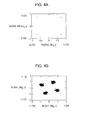
- Figs. 4A and 4B illustrate exemplary constellations that are obtained as a result of the reception and demodulation.
- Fig. 4A illustrates a case of an ideal reception state. In the ideal state, reception symbols are fixed into four positions. On the other hand, when the separation of the signals including the delay ⁇ is performed, the positions of reception symbols are not fixed and the demodulation ends in failure.
- the inventor recognizes the need for performing correct reception even though a relative delay occurs when a MIMO transmission is performed.
- a preamble signal is added to a transmission signal transmitted in the earliest timing among transmission signals that are modulated under an OFDM scheme, the transmission signals being output from individual transmission antennas under an MIMO scheme.
- the preamble signal is not added to the transmission signals except the transmission signal transmitted in the earliest timing.
- a communication device of the present disclosure includes a transmission signal processing unit that adds a preamble signal to a transmission signal transmitted in an earliest timing among plural transmission signals that are modulated under an OFDM scheme, the transmission signals being simultaneously transmitted under an MIMO scheme, and that does not add the preamble signal to the other transmission signals.
- the communication device includes a transmission antenna that separately transmits each of plural transmission signals that are generated by the transmission signal processing unit.
- a reception device of the present disclosure includes plural reception antennas that receive plural signals that are modulated under an OFDM scheme, the signals being simultaneously transmitted under an MIMO scheme, a synchronization processing unit that acquires a synchronization acquisition signal from a reception signal, and a reception processing unit that performs reception in a timing determined based on the synchronization acquisition signal.
- the synchronization processing unit determines a frame synchronization signal acquired from a preamble signal included in a specific reception signal received in an earliest timing among the signals that are received by the plural reception antennas to be the synchronization acquisition signal.
- the reception processing unit performs frame synchronization processing for a signal received by each of the reception antennas based on the synchronization acquisition signal acquired with the synchronization processing unit.
- signals of individual channels are properly received by respective reception paths on the reception side, even if a relative delay occurs between transmission signals that are simultaneously transmitted under a MIMO scheme.
- Fig. 5 is a diagram illustrating an example of a MIMO transmission device which is a communication device of the present disclosure.
- a MIMO transmission device 100 illustrated in Fig. 5 includes a transmission data processing unit 101.
- the transmission data processing unit 101 performs processing to generate transmission data of plural channels.
- the transmission data processing unit 101 generates three pieces of transmission data. Note that, generating the three pieces of transmission data is an example, and two or four or more pieces of transmission data may be generated.
- Transmission data for individual paths which are output from the transmission data processing unit 101, are supplied to IFFT units 102a, 102b, and 102c, and are subjected to inverse Fourier transform.
- Signals subjected to the inverse Fourier transform in the IFFT units 102a, 102b, and 102c are supplied to RF units (high frequency units) 104a, 104b, and 104c via digital-to-analog converters 103a, 103b, and 103c.
- Transmission signals that are converted into specified transmission frequencies with the RF units 104a, 104b, and 104c are wirelessly transmitted from antennas 105a, 105b, and 105c.
- a transmission signal TX#0 is wirelessly transmitted from the antenna 105a
- a transmission signal TX#1 is wirelessly transmitted from the antenna 105b
- a transmission signal TX#2 is wirelessly transmitted from the antenna 105c.
- the transmission signals TX#1 and TX#2 are wirelessly transmitted in the same frequency band.
- the MIMO transmission device 100 adds a preamble signal only to transmission data with the smallest relative delay for processing performed with a transmission processing system among the three pieces of transmission data generated with the transmission data processing unit 101.
- the transmission data processing unit 101 does not add the preamble signal to the rest of the transmission data.
- the transmission data processing unit 101 adds a null signal which is an invalid transmission signal to a section where the preamble signal is not added.
- a transmission processing system with the smallest relative delay is determined by measuring the property of each of transmission processing systems in advance, for example.
- Fig. 6 is a diagram illustrating the transmission states of the three transmission signals TX#0, TX#1, and TX#2.
- Each of the transmission signals TX#0, TX#1, and TX#2 is transmitted as an OFDM-modulated OFDM frame.
- a preamble signal tp0 is added only to the transmission signal TX#0 with the smallest relative delay (that is, transmitted earliest) among the three transmission signals TX#0 to TX#2.
- null signals that are invalid transmission signals are arranged.
- Real data or a pilot signal is arranged in a section other than the preamble signal provided in one OFDM frame.
- the preamble signal is provided to detect synchronization timing on the reception side. That is, on the reception side, processing including preparing a preamble replica signal having the same pattern as that of the preamble signal, detecting the correlation between a reception signal and the preamble replica signal, and detecting the timing of transmission of the preamble signal.
- the section where the preamble signal tp0 is arranged which is provided in the transmission signal TX#0, is determined to be the head part of an OFDM frame in Fig. 6 , it is not necessarily the head part.
- the preamble signal or the null signal may be arranged in substantially the center part of an OFDM frame.
- the pilot signal is used to estimate a transmission channel or to measure the state of each subcarrier during the channel estimation processing performed on the reception side.
- the channel estimation processing is performed after a fast Fourier transform is performed.
- the pilot signal is transmitted in timing which is varied among transmission paths.
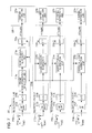
- Fig. 7 is a diagram illustrating an example of the MIMO reception device 200.
- the MIMO reception device 200 includes n+1 (n is any integer) reception paths 210a to 210n designated by #0 to #n.
- An RF unit 212a to which an antenna 211a is connected receives a signal of a specified frequency band.
- the reception signal acquired with the RF unit 212a is supplied to an analog-to-digital converter 213a, and is converted into digital data.
- Reception data output from the analog-to-digital converter 213a is supplied to a frame synchronization detection unit 214a that performs processing to detect a preamble signal included in the reception signal, and that outputs a frame synchronization signal indicating the transmission timing of one OFDM frame.
- the reception data output from the frame synchronization detection unit 214a is supplied to a guard interval elimination unit 215a, and the section of a guard interval, which is provided in one OFDM frame, is eliminated.
- the reception data from which the guard interval is eliminated with the guard interval elimination unit 215a is supplied to an FFT unit 216a, and data modulated into subcarriers is retrieved.
- the timing of eliminating the guard interval with the guard interval elimination unit 215a and the start timing of a fast Fourier operation performed with the FFT unit 216a are determined based on a frame synchronization signal output from the frame synchronization detection unit 214a.
- the reception data acquired with the FFT unit 216a is supplied to a reception signal processing unit 220 that includes a channel estimation unit 221a and that performs processing to estimate a transmission channel.
- a reception signal processing unit 220 that includes a channel estimation unit 221a and that performs processing to estimate a transmission channel.
- Concerning the reception paths 210b to 210n designated by #1 to #n, RF units 212b to 212n to which their respective antennas 211b to 211n are connected receive signals of the specified frequency band.
- the respective reception signals are supplied to analog-to-digital converters 213b to 213n and converted into digital data.
- Reception data output from the analog-to-digital converters 213b to 213n is supplied to the guard interval elimination units 215b to 215n.
- guard interval elimination units 215b to 125n of the reception paths 210b to 210n designated by #1 to #n processing to eliminate a guard interval is performed with reference to a frame synchronization signal output from the frame synchronization detection unit 214a of the reception path 210a designated by #0. Further, reception data output from the respective guard interval elimination units 215b to 215n is supplied to FFT units 216b to 216n, and data modulated into subcarriers is retrieved.
- the start timing of fast Fourier operations that are performed with the FFT units 216b to 216n of the reception paths 210b to 210n designated by #1 to #n is determined based on the frame synchronization signal output from the frame synchronization detection unit 214a of the reception path 210a designated by #0.
- the reception data acquired with the FFT units 216b to 216n is supplied to the reception signal processing unit 220 that includes channel estimation units 221b to 221n that are provided for the respective reception paths, and that performs processing to estimate transmission channels.
- each of the reception paths 210a to 210n designated by #0 to #n separately performs reception processing on a corresponding one of reception signals RX#0 to RX#n.
- reception processing can be appropriately performed for the signals of individual channels.
- the MIMO reception device 200 illustrated in Fig. 7 may perform the reception processing for the reception signals of individual channels, the reception signals including the preamble signals.
- Example of MIMO reception device Example where frame synchronization of each path is switched]
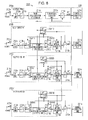
- Fig. 8 illustrates the configuration of a different MIMO reception device 200'.
- the MIMO reception device 200' of an example of Fig. 8 enables switching between reception processing performed when the preamble signal is transmitted by only one of the signals of plural paths and reception processing performed when the preamble signal is transmitted by each transmission signal.
- the reception path 210a designated by #0 is the same as the MIMO reception device 200 illustrated in Fig. 7 .
- the reception paths 210b' to 210n' designated by #1 to #n separately include frame synchronization detection units 214b to 214n, respectively.
- the frame synchronization detection units 214b to 214n detect the preamble signals from the respective reception signals RX#1 to RX#n, and acquire frame synchronization signals.
- selector switches SW11 to SWN1, and SW12 to SWN2 are connected, respectively.
- the connection of the selector switches SW11 to SWN1, and SW12 to SWN2 allows the reception paths 210b to 210n designated by #1 to #n to select a path where the preamble signal is detected and a path where the preamble signal is not detected with the frame synchronization detection units 214b to 214n.
- reception paths 210b' to 210n' designated by #1 to #n include selector switches SW10, SW20, ⁇ and SWN0.
- the selector switches SW10 to SWN0 perform switching between a frame synchronization signal detected with the frame synchronization detection unit 214a of the reception path 210a designated by #0 and frame synchronization signals that are detected with the frame synchronization units 214b to 214n of the reception paths 210b' to 210n' designated by #1 to #n.
- frame synchronization signals that are selected with the individual selector switches SW10 to SWN0 are supplied to the guard interval elimination units 215b to 215n and the FFT units 216b to 216n of the reception paths 210b' to 210n'.
- Each of the selector switches SW10 to SWN0, SW11 to SWN1, and SW12 to SWN2 performs switching based on, e.g., the mode of a reception signal. For example, when the preamble signal is included in the transmission signal of a single path illustrated in Fig. 6 , switching is performed to use only the frame synchronization detection unit 214a of the reception path 210a designated by #0. Further, when the preamble signal is included in the transmission signal of every path, frame synchronization signals that are detected with the individual frame synchronization units 214b to 214n are used on the reception paths 210b to 210n designated by #1 to #n.
- the MIMO reception device 200' illustrated in Fig. 8 it becomes possible to deal with either the case where a signal having the preamble signal included in only one of the plural paths is received or the case where the preamble signal is included in every reception signal.
- synchronization processing may be performed for each of the reception paths through the use of the preamble signal detected from the reception signal of a single path.
- Fig. 9 is a diagram illustrating a configuration for detecting the preamble signal through correlation detection performed with the frame synchronization detection unit 214a illustrated in Fig. 7 and Fig. 8 .
- the frame synchronization detection unit 214a includes an auto-correlation operation unit 231 and a cross-correlation operation unit 232.
- the auto-correlation operation unit 231 calculates the auto-correlation of a received preamble signal.
- the cross-correlation operation unit 232 calculates the cross correlation between a received preamble signal and a replica held by a preamble replica holding unit 233.
- the individual correlation values are multiplied with a multiplier 234, and a frame synchronization signal is acquired based on a value obtained by multiplying the correlations by each other.
- a frame synchronization signal having the peak position where the multiplication value is maximized to be the synchronization point is acquired.
- the earliest detected peak position among plural peak positions that are acquired based on the multiplication value is determined to be the synchronization point as illustrated in Fig. 9 as result (a). Then, a frame synchronization signal indicating the synchronization point is generated.
- the frame synchronization detection unit 214a of the present disclosure determines the single peak position (the first peak position) to be the synchronization point, and generates a frame synchronization signal indicating the synchronization point.
- pilot signals are transmitted from the MIMO transmission device.
- the pilot signals are arranged from individual transmission antennas in individual signals that are usually OFDM modulated so as not to overlap in terms of the time and the frequency range.
- the pilot signals that are arranged in sections except the guard intervals (GI) are set in timings that are different from each other.
- the relative delay ⁇ occurs between the two reception signals.
- the relative delay ⁇ is smaller than the length of the section of the guard interval (GI).
- elements h00 and h01 of (the H-matrix) are obtained based on the pilot signal of the path #0, and elements h10 and h11 of (the H-matrix) are obtained based on the pilot signal of the path #1 as illustrated in Fig. 10C .
- the relative delay ⁇ exists between the two reception signals as illustrated in parts A and B of Fig. 10 .
- synchronization acquisition processing is performed with the single frame synchronization detection unit 214a as illustrated in Fig. 7 , and a synchronization frame start point is set based on the reception data of the path #0 and fast Fourier transform is executed on each reception path as illustrated in part A of Fig. 10 . That is, every reception path executes the fast Fourier transform based on a transmission section Ta of the pilot signal illustrated in part A of Fig. 10 .
- the pilot signal of the elements of the H-matrix is detected from the result of subjecting the signal of a transmission section Tb displaced from the transmission section Ta by one OFDM frame to the fast Fourier transform, as illustrated in part B of Fig. 10 . That is, the relative delay ⁇ is added to the elements h10 and h11 of the (H-matrix), which are obtained based on the pilot signal of the path #1, as illustrated in part C of Fig. 10 .
- the fast Fourier operation is performed while the relative delay ⁇ is still included, the orthogonality is not disturbed by an operation by the fast Fourier transform as long as the relative delay ⁇ falls within the length of the guard interval.
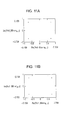
- Figs. 11A and 11B are examples where a result of demodulating reception data of the path #0 ( Fig. 11A ) and that of demodulating reception data of the path #1 ( Fig. 11B ) are simulated. The simulation of the example of Fig.
- the relative delay ⁇ is approximately 3.2 nsec which corresponds to one-tenth of an FFT slot of the LTE standard.
- a Rayleigh fading environment is envisioned. That is, a hundred scattered points are randomly arranged around a reception point, about 50 m in circumference, variations in phase and amplitude, which are caused by scattering from the scattered points, become random, and ray tracing is used to achieve propagation from the scattered points.
- QPSK-OFDM is used as for a signal.
- Fig. 11A and Fig. 11B illustrate the constellations of two receptions, which are achieved after signals are separated from the obtained H-matrix. It is apparent that both the constellations are restored. Here, it should be noted that the amount of restorable delay falls within the guard interval length.
- the reception device can perform processing properly.
- the frame synchronization detection unit 214a is provided for only one of the plural reception paths of the MIMO reception device so that the effect of a displacement of the synchronization point, which is caused by a displacement of the reception time of each reception path, can be eliminated. Therefore, even if the signal of each path, which is transmitted from the MIMO transmission device, has a relative delay, the reception processing can be performed properly. Accordingly, the plural transmission paths of the MIMO transmission device are allowed to perform transmission with a relative delay to some extent, and the MIMO transmission device can be easily configured as a result.
- the MIMO reception device of the present disclosure there is no need to provide the frame synchronization unit for each of the reception paths, and the configuration of the reception device can be simplified accordingly.
- the MIMO transmission device is configured so that the preamble signal is only provided in the transmission signal of a single path, which has the smallest relative delay among the plural transmission signals, and no preamble signal is provided in the transmission signals of the other paths as illustrated in Fig. 6 .
- the preamble signal is provided in each of plural signals that are transmitted from the MIMO transmission device to the MIMO reception device 200 illustrated in Fig. 7 .
- the reception paths 210b to 210n designated by #1 to #n which are included in the reception paths 210a to 210n designated by #0 to #n, which are provided in the MIMO reception device 200 illustrated in Fig. 7 , do not perform the synchronization detection processing.
- the reception processing can be properly performed by executing the synchronization processing on each reception path based on a frame synchronization signal detected from the earliest transmitted preamble signal on the reception side.
- the MIMO reception device 200 illustrated in Fig. 7 can be applied even though no special processing is performed on the transmission side, and contributes to the simplification of a MIMO reception device designed for a system performing communications by applying existing MIMO technologies.
- the MIMO reception device of the present disclosure can be applied to a reception device applied to a multiuser MIMO (MU-MIMO) where plural terminals are provided on the transmission side.
- MU-MIMO multiuser MIMO
- the present disclosure may have the following configurations.
- 11a, 11b antenna, 12a, 12b: high frequency unit (RF unit), 13a, 13b: analog-to-digital converter, 14a, 14b: matched filter, 15: correlation detection unit, 16a, 16b: guard interval elimination unit, 17a, 17b: FFT unit, 18: reception data processing unit, 100: MIMO transmission device, 101: transmission data processing unit, 102a, 102b, 102c: IFFT unit, 103a, 103b, 103c: digital-to-analog converter, 104a, 104b, 104c: high frequency unit (RF unit), 105a, 105b, 105c: antenna, 200, 200': MIMO reception device, 210a to 210n: reception path, 211a to 211n: antenna, 212a to 212n: RF unit, 213a to 213n: analog-to-digital converter, 214a to 214n: frame synchronization unit, 215a to 215n: guard interval elimination unit, 216a to
Landscapes
- Engineering & Computer Science (AREA)
- Computer Networks & Wireless Communication (AREA)
- Signal Processing (AREA)
- Radio Transmission System (AREA)
- Mobile Radio Communication Systems (AREA)
Abstract
Description
- This application is related to and claims priority under 35 U.S.C. §119(e) to Provisional Application Serial Number
61,693,349, filed August 27, 2012 - The present disclosure relates in general but not exclusively to a communication system to wirelessly transmit a signal modulated under an OFDM (Orthogonal Frequency Division Multiplexing) scheme, a communication device to which the communication system is applied, and a reception device to receive the wirelessly transmitted signal.
- In recent years, high-speed communications such as LTE (Long Term Evolution), WiMAX (Worldwide Interoperability for Microwave Access), etc. based on a modulation scheme using OFDM have been put to practical use. OFDM has guard intervals and therefore is highly usable in frequency selective multipath, and the implementation of MIMO (multiple-input and multiple-output) is easier in OFDM than in other modulation schemes. That is, since FFT (Fast Fourier Transform) allows signal processing in a frequency domain to be performed easily, the estimation of a complex channel matrix and the signal separation can be facilitated. Further, multiuser MIMO (MU-MIMO) establishing communications between a single base station and many terminals using the same frequency is considered as its applied technology.
- Although MIMO is targeted only for communications from the base station side, that is, downlink at present, researches are being conducted to apply MIMO to transmission from a mobile terminal (uplink) in the future. According to MIMO, high-speed communication is realized by transmitting different signals in parallel from plural antennas, which is, however, based on the premise that there are no delays between all signals and exact temporal agreement is achieved therebetween. In a base station, the agreement can be realized by implementing high-precision hardware. However, when performing MIMO transmission from a mobile terminal, it is difficult to attain accurate temporal agreement for each of plural transmission paths in the terminal. Highly precise synchronization techniques cannot be introduced into a mobile terminal because of its limited size and power consumption. Further, in the case of MU-MIMO, it is difficult to perform MIMO transmission due to a relative delay between terminals occurring in transmission.
- For the OFDM reception, there is a need to detect the FFT frame with accuracy. The circumstances where the frame detection is erroneously performed will be considered. When FFT is performed earlier than the original start of a frame and the original start point of the frame is inside a guard interval, the orthogonality of subcarriers after the FFT is retained. However, the guard interval length is reduced and it becomes impossible to avoid desired multipath. On the other hand, when the time of starting FFT is later than the original start point of the frame, an intersymbol interference occurs in the signal stream tail part and the orthogonality between subcarriers is not retained. Accordingly, many ideas are implemented to acquire synchronization in a receiver.
Fig. 1 illustrates areception device 10 receiving MIMO transmission by applying a modulation scheme using OFDM. - The
reception device 10 ofFig. 1 has two reception paths of apath # 0 and apath # 1. The reception path of thepath # 0 includes a high frequency unit (hereinafter referred to as an "RF unit") 12a to which anantenna 11a is connected. A signal received with theRF unit 12a is converted into digital data with an analog-to-digital converter 13a. The data converted with the analog-to-digital converter 13a is supplied to acorrelation detection unit 15 via a matchedfilter 14a configured to detect a preamble. Thecorrelation detection unit 15 detects the head position (synchronization point) of an FFT frame through auto-correlation or cross-correlation. A guardinterval elimination unit 16a eliminates a guard interval from a received FFT frame based on the head of the FFT frame, which is detected with thecorrelation detection unit 15. - Data from which the guard interval is eliminated with the guard
interval elimination unit 16a is supplied to anFFT unit 17a, data modulated into individual subcarriers with theFFT unit 17a is retrieved, and the retrieved reception data of thepath # 0 is supplied to a receptiondata processing unit 18. - As for the reception path of the
path # 1, the configuration is the same as that of the reception path of thepath # 0. That is, a signal received with anRF unit 12b to which anantenna 11b is connected is supplied to an analog-to-digital converter 13b, a matchedfilter 14b, thecorrelation detection unit 15, a guardinterval elimination unit 16b, and anFFT unit 17b in sequence, and reception data of thepath # 1 is supplied to the receptiondata processing unit 18. - In
Patent Literature 1, detection of the head of an FFT frame through an auto-correlation operation and a cross-correlation operation is disclosed. - As illustrated in
Fig. 1 , in the case of the reception device for MIMO, there is a necessity to collect the signals of individual reception branches to perform the operation of auto-correlation or cross-correlation with thecorrelation detection unit 15. Processing of this kind is performed based on the premise that both the times and the frequencies of signals that are transmitted from plural antennas on the transmission side exactly agree with one another. - However, when an MIMO transmission is performed on the uplink in the future, it is assumed that there will be the circumstances where the accuracy of times or frequencies cannot be ensured between signals that are transmitted from the plural antennas on the transmission side. That is, when a mobile terminal performs the MIMO transmission, transmission signals that are output from a transmission data processing system in the mobile terminal may have respective delays before reaching the antennas of individual channels, which prevent synchronization between the antennas. Factors responsible for the respective delays include the difference between the group delays of power amplifiers, the difference between the group delays of transmission bandpass filters, and the difference between the group delays of various notch filters and matching circuits.
- For example, there are differences between the group delays of power amplifiers due to the differences between active elements constituting the amplifiers. Although the power amplifiers have the same configuration, there are further differences between group delays depending on a temperature or an applied voltage. When there are two antennas, a group delay difference of a few nsec occurs.
- The transmission bandpass filter has a group delay of about 10 nsec, which is significantly dependent on a pass band or an ambient temperature.
- Whether or not the various notch filters should be installed on individual paths is determined according to the respective circumstances, although significantly depending on the performances of parts to be used, to reduce components interfering with other bands. The matching circuits are installed in consideration of the characteristics of elements to satisfy the characteristics between the elements. The circuit configuration and number of parts thereof are variable, and it is often necessary to provide two paths having different configurations. Recovery from this kind of delays can be achieved by performing phase correction when the delay amounts are obtained in advance. However, the delay amount of a mobile terminal usually varies from terminal to terminal. Further, it is difficult to estimate the delay amount due to its fluctuation with temperature and fluctuation over time.
- Further, when an MIMO transmission is performed on the uplink, a problem occurs when channel estimation is performed. According to MIMO, a channel is represented by a determinant (hereinafter referred to as an "H-matrix".). The H-matrix is estimated based on pilots that are provided in transmission signals, and signals are separated. However, when the displacement of a FFT frame occurs between the transmission signals due to a relative delay, fixation on any single point causes the problem of incorrect demodulation of the pilot. The pilots are arranged so that the frequencies and the time ranges of OFDM do not overlap one another between plural transmission paths. Therefore, if each of FFT frames where the pilots are arranged can be specified in some way, the pilots can be correctly found out.
- That is, when there are two paths of the
reception path # 0 and thereception path # 1 as illustrated inFig. 2 , FFT frames where the pilots are arranged are in different timings. GI denotes a guard interval. In this example, a relative delay of about 4 nsec occurs between tworeception paths # reception path # 0, a section a where a pilot signal has been transmitted is detected, and demodulation is performed in synchronization with the timing. Further, on thereception path # 1, a section b where a pilot signal has been transmitted is also detected, and demodulation is performed in synchronization with the timing. The transmission signals of this example are signals modulated with QPSK. - When performing receptions as illustrated in
Fig. 2 , MIMO channels are expressed in matrix form as illustrated at the lower left ofFig. 3 . h00 and h01 are estimated from thepath # 0, and h10 and h11 are estimated from thepath # 1. At that time, a time delay occurring between the two paths does not affect a reception pilot due to the processing of frame synchronization. Here, the data reception begins, and pieces of data of the two paths temporally overlap each other during transmission. The pieces of data are demodulated by separating signals of the two paths by the use of an inverse matrix of the previously obtained H-matrix. At that time, however, the pieces of reception data of the two paths include a delay δ between the paths as illustrated inFig. 2 . Therefore, the demodulation is performed with the phase shift, which interferes with the proper signal separation. That is, the separation of signals including the delay δ is performed by the use of the H-matrix which is not affected by the delay δ. -
Figs. 4A and 4B illustrate exemplary constellations that are obtained as a result of the reception and demodulation.Fig. 4A illustrates a case of an ideal reception state. In the ideal state, reception symbols are fixed into four positions. On the other hand, when the separation of the signals including the delay δ is performed, the positions of reception symbols are not fixed and the demodulation ends in failure. - The inventor recognizes the need for performing correct reception even though a relative delay occurs when a MIMO transmission is performed.
- According to a communication system of the present disclosure, a preamble signal is added to a transmission signal transmitted in the earliest timing among transmission signals that are modulated under an OFDM scheme, the transmission signals being output from individual transmission antennas under an MIMO scheme.
- The preamble signal is not added to the transmission signals except the transmission signal transmitted in the earliest timing.
- Further, a communication device of the present disclosure includes a transmission signal processing unit that adds a preamble signal to a transmission signal transmitted in an earliest timing among plural transmission signals that are modulated under an OFDM scheme, the transmission signals being simultaneously transmitted under an MIMO scheme, and that does not add the preamble signal to the other transmission signals. The communication device includes a transmission antenna that separately transmits each of plural transmission signals that are generated by the transmission signal processing unit.
- Further, a reception device of the present disclosure includes plural reception antennas that receive plural signals that are modulated under an OFDM scheme, the signals being simultaneously transmitted under an MIMO scheme, a synchronization processing unit that acquires a synchronization acquisition signal from a reception signal, and a reception processing unit that performs reception in a timing determined based on the synchronization acquisition signal.
- The synchronization processing unit determines a frame synchronization signal acquired from a preamble signal included in a specific reception signal received in an earliest timing among the signals that are received by the plural reception antennas to be the synchronization acquisition signal.
- The reception processing unit performs frame synchronization processing for a signal received by each of the reception antennas based on the synchronization acquisition signal acquired with the synchronization processing unit.
- According to the present disclosure, signals of individual channels are properly received by respective reception paths on the reception side, even if a relative delay occurs between transmission signals that are simultaneously transmitted under a MIMO scheme.
- Various respective aspects and features of the invention are defined in the appended claims. Combinations of features from the dependent claims may be combined with features of the independent claims as appropriate and not merely as explicitly set out in the claims.
- Embodiments of the invention will now be described with reference to the accompanying drawings, throughout which like parts are referred to by like references, and in which:
-
Fig. 1 is a block diagram illustrating an exemplary MIMO reception device according to related art. -
Fig. 2 is a diagram illustrating an exemplary transmission state of MIMO. -
Fig. 3 is a diagram illustrating an exemplary channel estimation of MIMO. -
Figs. 4A and 4B are characteristic diagrams illustrating a reception state of MIMO.Fig. 4A is a characteristic diagram illustrating an ideal reception state of MIMO.Fig. 4B is a characteristic diagram illustrating a reception state of MIMO, which is attained when a channel includes a transmission delay. -
Fig. 5 is a block diagram illustrating an exemplary MIMO transmission device according to an embodiment of the present disclosure. -
Fig. 6 is a diagram illustrating an exemplary transmission state according to an embodiment of the present disclosure. -
Fig. 7 is a block diagram illustrating an exemplary MIMO reception device according to an embodiment of the present disclosure. -
Fig. 8 is a block diagram illustrating an exemplary MIMO reception device (an example where switching is enabled) according to an embodiment of the present disclosure. -
Fig. 9 is a configuration diagram illustrating an exemplary frame synchronization unit according to an embodiment of the present disclosure. -
Fig. 10 is a diagram illustrating an exemplary channel estimation according to an embodiment of the present disclosure. -
Figs. 11A and 11B are diagrams illustrating exemplary transmission states according to an embodiment of the present disclosure. - Hereinafter, an exemplary embodiment of the present disclosure will be described with reference to
Fig. 5 to Fig. 11 in the following order. - 1. Example of MIMO transmission device (
Fig. 5 ) - 2. Example of transmission signal (
Fig. 6 ) - 3. Example of MIMO reception device (
Fig. 7 ) - 4. Example of MIMO reception device: Example where frame synchronization of each path is switched (
Fig. 8 ) - 5. Example of frame synchronization unit (
Fig. 9 ) - 6. Example of channel estimation (
Fig. 10 andFig. 11 ) - 7. Example of modification
-
Fig. 5 is a diagram illustrating an example of a MIMO transmission device which is a communication device of the present disclosure. - A
MIMO transmission device 100 illustrated inFig. 5 includes a transmissiondata processing unit 101. The transmissiondata processing unit 101 performs processing to generate transmission data of plural channels. In the example ofFig. 5 , the transmissiondata processing unit 101 generates three pieces of transmission data. Note that, generating the three pieces of transmission data is an example, and two or four or more pieces of transmission data may be generated. - Transmission data for individual paths, which are output from the transmission
data processing unit 101, are supplied toIFFT units IFFT units analog converters RF units antennas - For example, a transmission
signal TX# 0 is wirelessly transmitted from theantenna 105a, and a transmissionsignal TX# 1 is wirelessly transmitted from theantenna 105b. Further, a transmissionsignal TX# 2 is wirelessly transmitted from theantenna 105c. The transmission signalsTX# 1 andTX# 2 are wirelessly transmitted in the same frequency band. - Here, the
MIMO transmission device 100 according to an example of the present disclosure adds a preamble signal only to transmission data with the smallest relative delay for processing performed with a transmission processing system among the three pieces of transmission data generated with the transmissiondata processing unit 101. The transmissiondata processing unit 101 does not add the preamble signal to the rest of the transmission data. The transmissiondata processing unit 101 adds a null signal which is an invalid transmission signal to a section where the preamble signal is not added. - A transmission processing system with the smallest relative delay is determined by measuring the property of each of transmission processing systems in advance, for example.
-
Fig. 6 is a diagram illustrating the transmission states of the three transmissionsignals TX# 0,TX# 1, andTX# 2. - Each of the transmission signals
TX# 0,TX# 1, andTX# 2 is transmitted as an OFDM-modulated OFDM frame. In an example of the present disclosure, a preamble signal tp0 is added only to the transmissionsignal TX# 0 with the smallest relative delay (that is, transmitted earliest) among the three transmissionsignals TX# 0 toTX# 2. In sections tn1 and tn2 to which the preamble signals of the transmission signalsTX# 1 andTX# 2 that are transmitted later than the transmissionsignal TX# 0 are to be added, null signals that are invalid transmission signals are arranged. Real data or a pilot signal is arranged in a section other than the preamble signal provided in one OFDM frame. - The preamble signal is provided to detect synchronization timing on the reception side. That is, on the reception side, processing including preparing a preamble replica signal having the same pattern as that of the preamble signal, detecting the correlation between a reception signal and the preamble replica signal, and detecting the timing of transmission of the preamble signal.
- Although the section where the preamble signal tp0 is arranged, which is provided in the transmission
signal TX# 0, is determined to be the head part of an OFDM frame inFig. 6 , it is not necessarily the head part. For example, the preamble signal or the null signal may be arranged in substantially the center part of an OFDM frame. - Note that, the pilot signal is used to estimate a transmission channel or to measure the state of each subcarrier during the channel estimation processing performed on the reception side. The channel estimation processing is performed after a fast Fourier transform is performed. The pilot signal is transmitted in timing which is varied among transmission paths.
- Next, a
MIMO reception device 200 receiving a signal transmitted from theMIMO transmission device 100 will be described. -
Fig. 7 is a diagram illustrating an example of theMIMO reception device 200. TheMIMO reception device 200 includes n+1 (n is any integer)reception paths 210a to 210n designated by #0 to #n. - An explanation for the
reception path 210a designated by #0 will be given. AnRF unit 212a to which anantenna 211a is connected receives a signal of a specified frequency band. The reception signal acquired with theRF unit 212a is supplied to an analog-to-digital converter 213a, and is converted into digital data. Reception data output from the analog-to-digital converter 213a is supplied to a framesynchronization detection unit 214a that performs processing to detect a preamble signal included in the reception signal, and that outputs a frame synchronization signal indicating the transmission timing of one OFDM frame. - The reception data output from the frame
synchronization detection unit 214a is supplied to a guardinterval elimination unit 215a, and the section of a guard interval, which is provided in one OFDM frame, is eliminated. The reception data from which the guard interval is eliminated with the guardinterval elimination unit 215a is supplied to anFFT unit 216a, and data modulated into subcarriers is retrieved. The timing of eliminating the guard interval with the guardinterval elimination unit 215a and the start timing of a fast Fourier operation performed with theFFT unit 216a are determined based on a frame synchronization signal output from the framesynchronization detection unit 214a. The reception data acquired with theFFT unit 216a is supplied to a receptionsignal processing unit 220 that includes achannel estimation unit 221a and that performs processing to estimate a transmission channel. Concerning thereception paths 210b to 210n designated by #1 to #n,RF units 212b to 212n to which theirrespective antennas 211b to 211n are connected receive signals of the specified frequency band. The respective reception signals are supplied to analog-to-digital converters 213b to 213n and converted into digital data. Reception data output from the analog-to-digital converters 213b to 213n is supplied to the guardinterval elimination units 215b to 215n. In the guardinterval elimination units 215b to 125n of thereception paths 210b to 210n designated by #1 to #n, processing to eliminate a guard interval is performed with reference to a frame synchronization signal output from the framesynchronization detection unit 214a of thereception path 210a designated by #0. Further, reception data output from the respective guardinterval elimination units 215b to 215n is supplied toFFT units 216b to 216n, and data modulated into subcarriers is retrieved. The start timing of fast Fourier operations that are performed with theFFT units 216b to 216n of thereception paths 210b to 210n designated by #1 to #n is determined based on the frame synchronization signal output from the framesynchronization detection unit 214a of thereception path 210a designated by #0. The reception data acquired with theFFT units 216b to 216n is supplied to the receptionsignal processing unit 220 that includeschannel estimation units 221b to 221n that are provided for the respective reception paths, and that performs processing to estimate transmission channels. - In the
MIMO reception device 200 illustrated inFig. 7 , each of thereception paths 210a to 210n designated by #0 to #n separately performs reception processing on a corresponding one of receptionsignals RX# 0 to RX#n. According to theMIMO reception device 200 illustrated inFig. 7 , even if a signal including the preamble signal which is only included in the transmission signal of one of plural paths is received as illustrated inFig. 6 , reception processing can be appropriately performed for the signals of individual channels. However, theMIMO reception device 200 illustrated inFig. 7 may perform the reception processing for the reception signals of individual channels, the reception signals including the preamble signals. -
Fig. 8 illustrates the configuration of a different MIMO reception device 200'. - The MIMO reception device 200' of an example of
Fig. 8 enables switching between reception processing performed when the preamble signal is transmitted by only one of the signals of plural paths and reception processing performed when the preamble signal is transmitted by each transmission signal. - In the MIMO reception device 200' illustrated in
Fig. 8 , the same parts as those of theMIMO reception device 200 illustrated inFig. 7 are designated by the same reference signs. - The
reception path 210a designated by #0 is the same as theMIMO reception device 200 illustrated inFig. 7 . Thereception paths 210b' to 210n' designated by #1 to #n separately include framesynchronization detection units 214b to 214n, respectively. The framesynchronization detection units 214b to 214n detect the preamble signals from the respective receptionsignals RX# 1 to RX#n, and acquire frame synchronization signals. - In the preceding and subsequent stages of the frame
synchronization detection units 214b to 214n, selector switches SW11 to SWN1, and SW12 to SWN2 are connected, respectively. The connection of the selector switches SW11 to SWN1, and SW12 to SWN2 allows thereception paths 210b to 210n designated by #1 to #n to select a path where the preamble signal is detected and a path where the preamble signal is not detected with the framesynchronization detection units 214b to 214n. - Further, the
reception paths 210b' to 210n' designated by #1 to #n include selector switches SW10, SW20, ··· and SWN0. The selector switches SW10 to SWN0 perform switching between a frame synchronization signal detected with the framesynchronization detection unit 214a of thereception path 210a designated by #0 and frame synchronization signals that are detected with theframe synchronization units 214b to 214n of thereception paths 210b' to 210n' designated by #1 to #n. - Then, frame synchronization signals that are selected with the individual selector switches SW10 to SWN0 are supplied to the guard
interval elimination units 215b to 215n and theFFT units 216b to 216n of thereception paths 210b' to 210n'. - Each of the selector switches SW10 to SWN0, SW11 to SWN1, and SW12 to SWN2 performs switching based on, e.g., the mode of a reception signal. For example, when the preamble signal is included in the transmission signal of a single path illustrated in
Fig. 6 , switching is performed to use only the framesynchronization detection unit 214a of thereception path 210a designated by #0. Further, when the preamble signal is included in the transmission signal of every path, frame synchronization signals that are detected with the individualframe synchronization units 214b to 214n are used on thereception paths 210b to 210n designated by #1 to #n. - According to the MIMO reception device 200' illustrated in
Fig. 8 , it becomes possible to deal with either the case where a signal having the preamble signal included in only one of the plural paths is received or the case where the preamble signal is included in every reception signal. However, even if the preamble signal is included in every reception signal, synchronization processing may be performed for each of the reception paths through the use of the preamble signal detected from the reception signal of a single path. -
Fig. 9 is a diagram illustrating a configuration for detecting the preamble signal through correlation detection performed with the framesynchronization detection unit 214a illustrated inFig. 7 andFig. 8 . - Here, the assumption is made that the preamble signal of the
path # 0 and the preamble signal of thepath # 1 are included in a reception signal. A relative delay δ occurs between the two signals. - As illustrated in
Fig. 9 , the framesynchronization detection unit 214a includes an auto-correlation operation unit 231 and across-correlation operation unit 232. The auto-correlation operation unit 231 calculates the auto-correlation of a received preamble signal. Thecross-correlation operation unit 232 calculates the cross correlation between a received preamble signal and a replica held by a preamblereplica holding unit 233. - Then, the individual correlation values are multiplied with a multiplier 234, and a frame synchronization signal is acquired based on a value obtained by multiplying the correlations by each other.
- When acquiring the frame synchronization signal based on the correlation value in the past, a frame synchronization signal having the peak position where the multiplication value is maximized to be the synchronization point is acquired.
- In the frame
synchronization detection unit 214a of the present disclosure, the earliest detected peak position among plural peak positions that are acquired based on the multiplication value is determined to be the synchronization point as illustrated inFig. 9 as result (a). Then, a frame synchronization signal indicating the synchronization point is generated. - Here, when the preamble signal is included only in the signal of a single path as illustrated in
Fig. 6 , a single peak position based on the preamble signal is detected as illustrated inFig. 9 as result (b). The framesynchronization detection unit 214a of the present disclosure determines the single peak position (the first peak position) to be the synchronization point, and generates a frame synchronization signal indicating the synchronization point. - By thus determining the first detected peak position to be the synchronization point and performing the reception processing for every reception path based on the frame synchronization signal indicating the synchronization point, an intersymbol interference occurring in the tail part of a signal having been subjected to the guard interval elimination can be avoided and the orthogonality between subcarriers after fast Fourier transform can be retained.
- Next, a channel estimation according to an example of the present disclosure will be described with reference to
Fig. 10 andFig. 11 . For performing the MIMO reception, there is a necessity to obtain a channel matrix (H-matrix) to separate the reception data of each channel. - On this account, pilot signals are transmitted from the MIMO transmission device. The pilot signals are arranged from individual transmission antennas in individual signals that are usually OFDM modulated so as not to overlap in terms of the time and the frequency range.
- For example, as illustrated in
Fig. 10 , upon receiving the reception signal of the path #0 (Part A ofFig. 10 ) and the reception signal of the path #1 (Part B ofFig. 10 ), the pilot signals that are arranged in sections except the guard intervals (GI) are set in timings that are different from each other. In this example ofFig. 10 , the relative delay δ occurs between the two reception signals. The relative delay δ is smaller than the length of the section of the guard interval (GI). - Under these circumstances, elements h00 and h01 of (the H-matrix) are obtained based on the pilot signal of the
path # 0, and elements h10 and h11 of (the H-matrix) are obtained based on the pilot signal of thepath # 1 as illustrated inFig. 10C . Here, the relative delay δ exists between the two reception signals as illustrated in parts A and B ofFig. 10 . - In an example of the present disclosure, synchronization acquisition processing is performed with the single frame
synchronization detection unit 214a as illustrated inFig. 7 , and a synchronization frame start point is set based on the reception data of thepath # 0 and fast Fourier transform is executed on each reception path as illustrated in part A ofFig. 10 . That is, every reception path executes the fast Fourier transform based on a transmission section Ta of the pilot signal illustrated in part A ofFig. 10 . - Accordingly, on the
reception path 210b designated by #1, the pilot signal of the elements of the H-matrix is detected from the result of subjecting the signal of a transmission section Tb displaced from the transmission section Ta by one OFDM frame to the fast Fourier transform, as illustrated in part B ofFig. 10 . That is, the relative delay δ is added to the elements h10 and h11 of the (H-matrix), which are obtained based on the pilot signal of thepath # 1, as illustrated in part C ofFig. 10 . - Therefore, although the fast Fourier operation is performed while the relative delay δ is still included, the orthogonality is not disturbed by an operation by the fast Fourier transform as long as the relative delay δ falls within the length of the guard interval.
- Then, when the channel estimation is performed for the H-matrix, the estimation of the H-matrix is performed while the relative delay δ is still included, as illustrated in part C of
Fig. 10 , which means that each of subcarrier components of the pilot signal after the fast Fourier transform includes phase rotation caused by the relative delay δ. Accordingly, data is properly restored when both the pilot signal and the data have the same relative delay.Figs. 11A and 11B are examples where a result of demodulating reception data of the path #0 (Fig. 11A ) and that of demodulating reception data of the path #1 (Fig. 11B ) are simulated. The simulation of the example ofFig. 11 is performed on condition that the relative delay δ is approximately 3.2 nsec which corresponds to one-tenth of an FFT slot of the LTE standard. Further, a Rayleigh fading environment is envisioned. That is, a hundred scattered points are randomly arranged around a reception point, about 50 m in circumference, variations in phase and amplitude, which are caused by scattering from the scattered points, become random, and ray tracing is used to achieve propagation from the scattered points. As for a signal, QPSK-OFDM is used. -
Fig. 11A and Fig. 11B illustrate the constellations of two receptions, which are achieved after signals are separated from the obtained H-matrix. It is apparent that both the constellations are restored. Here, it should be noted that the amount of restorable delay falls within the guard interval length. - For example, even though the guard interval length is set to about 5 µsec according to the LTE standard, the relative delay δ that actually occurs is about 10 nsec. Therefore, the reception device can perform processing properly.
- As described above, according to the present disclosure, the frame
synchronization detection unit 214a is provided for only one of the plural reception paths of the MIMO reception device so that the effect of a displacement of the synchronization point, which is caused by a displacement of the reception time of each reception path, can be eliminated. Therefore, even if the signal of each path, which is transmitted from the MIMO transmission device, has a relative delay, the reception processing can be performed properly. Accordingly, the plural transmission paths of the MIMO transmission device are allowed to perform transmission with a relative delay to some extent, and the MIMO transmission device can be easily configured as a result. - Further, in the MIMO reception device of the present disclosure, there is no need to provide the frame synchronization unit for each of the reception paths, and the configuration of the reception device can be simplified accordingly.
- According to the above description, the MIMO transmission device is configured so that the preamble signal is only provided in the transmission signal of a single path, which has the smallest relative delay among the plural transmission signals, and no preamble signal is provided in the transmission signals of the other paths as illustrated in
Fig. 6 . - On the other hand, it may be arranged such that the preamble signal is provided in each of plural signals that are transmitted from the MIMO transmission device to the
MIMO reception device 200 illustrated inFig. 7 . - That is, even though the preamble signal is included in a reception signal, the
reception paths 210b to 210n designated by #1 to #n, which are included in thereception paths 210a to 210n designated by #0 to #n, which are provided in theMIMO reception device 200 illustrated inFig. 7 , do not perform the synchronization detection processing. Thus, even though the preamble signal is provided in each of the plural signals, the reception processing can be properly performed by executing the synchronization processing on each reception path based on a frame synchronization signal detected from the earliest transmitted preamble signal on the reception side. Accordingly, theMIMO reception device 200 illustrated inFig. 7 can be applied even though no special processing is performed on the transmission side, and contributes to the simplification of a MIMO reception device designed for a system performing communications by applying existing MIMO technologies. - Further, the MIMO reception device of the present disclosure can be applied to a reception device applied to a multiuser MIMO (MU-MIMO) where plural terminals are provided on the transmission side.
- The present disclosure may have the following configurations.
- (1)
A communication system wherein a preamble signal is added to a transmission signal transmitted in an earliest timing among transmission signals that are modulated under an OFDM scheme, the transmission signals being output from individual transmission antennas under an MIMO scheme; and
wherein the preamble signal is not added to the transmission signals except the transmission signal transmitted in the earliest timing. - (2)
The communication system according to (1),
wherein, in the transmission signals except the transmission signal transmitted in the earliest timing, a null signal is provided in a section of the preamble signal. - (3)
The communication system according to (1) or (2),
wherein a reception device receiving the transmission signal determines a frame synchronization signal acquired based on the preamble signal received by a first reception antenna among plural reception antennas to be a synchronization acquisition signal, and uses the acquired synchronization acquisition signal to perform frame synchronization processing for a signal received by each of the reception antennas. - (4) A communication device comprising:
- a transmission signal processing unit that adds a preamble signal to a transmission signal transmitted in an earliest timing among plural transmission signals that are modulated under an OFDM scheme, the transmission signals being simultaneously transmitted under a MIMO scheme, and that does not add the preamble signal to the other transmission signals; and
- transmission antennas that separately transmit plural transmission signals that are generated with the transmission signal processing unit.
- (5)
A reception device comprising:- plural reception antennas that receive plural signals that are modulated under an OFDM scheme, the signals being simultaneously transmitted under a MIMO scheme;
- a synchronization processing unit that determines a frame synchronization signal acquired based on a preamble signal included in a specific reception signal received in an earliest timing among the signals that are received by the plural reception antennas to be a synchronization acquisition signal; and
- a reception processing unit that performs frame synchronization processing for a signal received by each of the reception antennas based on the synchronization acquisition signal acquired with the synchronization processing unit.
- (6)
The reception device according to (5),
wherein the reception processing unit selects a case where the frame synchronization signal acquired based on the preamble signal included in the specific reception signal is used as the synchronization acquisition signal of each of the reception signals or a case where a frame synchronization signal acquired based on a preamble signal included in a signal received by a reception antenna of each system is used as the synchronization acquisition signal. In addition, the configurations or the processing procedures that are written in Claims of the present disclosure are not limited to the above-described exemplary embodiments. It should be understood by those skilled in the art that various modifications, combinations, and other exemplary embodiments may occur depending on design and/or other factors insofar as they are within the scope of the claims, as a matter of course. - In so far as the embodiments of the invention described above are implemented, at least in part, using software-controlled data processing apparatus, it will be appreciated that a computer program providing such software control and a transmission, storage or other medium by which such a computer program is provided are envisaged as aspects of the present invention.
- 11a, 11b: antenna, 12a, 12b: high frequency unit (RF unit), 13a, 13b: analog-to-digital converter, 14a, 14b: matched filter, 15: correlation detection unit, 16a, 16b: guard interval elimination unit, 17a, 17b: FFT unit, 18: reception data processing unit, 100: MIMO transmission device, 101: transmission data processing unit, 102a, 102b, 102c: IFFT unit, 103a, 103b, 103c: digital-to-analog converter, 104a, 104b, 104c: high frequency unit (RF unit), 105a, 105b, 105c: antenna, 200, 200': MIMO reception device, 210a to 210n: reception path, 211a to 211n: antenna, 212a to 212n: RF unit, 213a to 213n: analog-to-digital converter, 214a to 214n: frame synchronization unit, 215a to 215n: guard interval elimination unit, 216a to 216n: FFT unit, 220: reception data processing unit, 221a to 221n: channel estimation unit, 231: auto-correlation operation unit, 232: cross-correlation operation unit, 233: preamble replica holding unit, 234: multiplier
Claims (6)
- A communication system comprising:a transmission device having a plurality of transmission antennas that transmit a plurality of signals under a multiple input multiple output (MIMO) scheme; anda reception device having a plurality of reception antennas that receive the plurality of signals under the MIMO scheme,wherein the transmission device is configured to add a preamble signal to a transmission signal transmitted to the reception device at an earliest timing among transmission signals that are modulated under an orthogonal frequency division multiplexing (OFDM) scheme, the transmission signals being output from the transmission antennas; andwherein the transmission device does not add the preamble signal to the transmission signals other than the transmission signal transmitted at the earliest timing.
- The communication system according to Claim 1,
wherein, in the transmission signals other than the transmission signal transmitted at the earliest timing, a null signal is provided in a section of the preamble signal. - The communication system according to Claim 1,
wherein the reception device determines a frame synchronization signal acquired based on the preamble signal received by a first reception antenna among the plurality of reception antennas to be a synchronization acquisition signal, and uses the acquired synchronization acquisition signal to perform frame synchronization processing for a signal received by each of the reception antennas. - A communication device comprising:a transmission signal processing unit that adds a preamble signal to a transmission signal transmitted in an earliest timing among plural transmission signals that are modulated under an orthogonal frequency division multiplexing (OFDM) scheme, the transmission signals being simultaneously transmitted under a multiple input multiple output (MIMO) scheme, and that does not add the preamble signal to the other transmission signals; anda plurality of transmission antennas that separately transmit plural transmission signals that are generated with the transmission signal processing unit.
- A reception device comprising:a plurality of reception antennas that receive plural signals that are modulated under an orthogonal frequency division multiplexing (OFDM) scheme, the signals being simultaneously transmitted under a multiple input multiple output (MIMO) scheme;a synchronization processing unit that determines a frame synchronization signal acquired based on a preamble signal included in a specific reception signal received at an earliest timing among the signals that are received by the plurality of reception antennas to be a synchronization acquisition signal; anda reception processing unit that performs frame synchronization processing for a signal received by each of the reception antennas based on the synchronization acquisition signal acquired with the synchronization processing unit.
- The reception device according to Claim 5,
wherein the reception processing unit selects a case where the frame synchronization signal acquired based on the preamble signal included in the specific reception signal is used as the synchronization acquisition signal of each of the reception signals or a case where a frame synchronization signal acquired based on a preamble signal included in a signal received by a reception antenna of each system is used as the synchronization acquisition signal.
Applications Claiming Priority (1)
| Application Number | Priority Date | Filing Date | Title |
|---|---|---|---|
| US201261693349P | 2012-08-27 | 2012-08-27 |
Publications (3)
| Publication Number | Publication Date |
|---|---|
| EP2704347A2 true EP2704347A2 (en) | 2014-03-05 |
| EP2704347A3 EP2704347A3 (en) | 2018-01-03 |
| EP2704347B1 EP2704347B1 (en) | 2019-07-03 |
Family
ID=48985611
Family Applications (1)
| Application Number | Title | Priority Date | Filing Date |
|---|---|---|---|
| EP13180211.8A Not-in-force EP2704347B1 (en) | 2012-08-27 | 2013-08-13 | Preamble for mimo frame synchronization |
Country Status (3)
| Country | Link |
|---|---|
| US (1) | US9118363B2 (en) |
| EP (1) | EP2704347B1 (en) |
| CN (2) | CN103634258B (en) |
Families Citing this family (3)
| Publication number | Priority date | Publication date | Assignee | Title |
|---|---|---|---|---|
| CN105141407A (en) * | 2015-08-21 | 2015-12-09 | 深圳市晓渡云科技有限公司 | Multi-user anti-interference synchronization method and multi-user anti-interference synchronization device |
| FR3089728B1 (en) * | 2018-12-10 | 2022-04-15 | Sagemcom Energy & Telecom Sas | Device for receiving PLC signals |
| CN111030956B (en) * | 2019-10-30 | 2021-06-08 | 华为技术有限公司 | A communication method and device |
Citations (1)
| Publication number | Priority date | Publication date | Assignee | Title |
|---|---|---|---|---|
| JP2006238367A (en) | 2005-02-28 | 2006-09-07 | Mitsubishi Electric Corp | Demodulation timing generation circuit and demodulator |
Family Cites Families (12)
| Publication number | Priority date | Publication date | Assignee | Title |
|---|---|---|---|---|
| US20060072681A1 (en) * | 2004-10-01 | 2006-04-06 | Texas Instruments Incorporated | Scalable gain retraining generator, method of gain retraining and multiple-input, multiple-output communications system employing the generator or method |
| US9084260B2 (en) * | 2005-10-26 | 2015-07-14 | Intel Corporation | Systems for communicating using multiple frequency bands in a wireless network |
| KR100973585B1 (en) * | 2005-12-10 | 2010-08-02 | 한국전자통신연구원 | Method and apparatus for estimating timing error and frequency offset in MIO mobile communication system |
| US7809344B2 (en) * | 2006-07-20 | 2010-10-05 | Industrial Technology Research Institute | Fractional carrier frequency offset estimator and method of estimating fractional carrier frequency offset between transmitter and receiver |
| CN101163124B (en) * | 2006-10-13 | 2010-05-19 | 中兴通讯股份有限公司 | A Method for Realizing Time Synchronization of Multiple-Input Multiple-Output Orthogonal Frequency Division Multiplexing System |
| TWI473484B (en) * | 2008-03-10 | 2015-02-11 | Koninkl Philips Electronics Nv | A physical layer convergence protocol (plcp) packet structure for multiple-input-multiple-output (mimo) communication systems |
| JP5182757B2 (en) * | 2008-11-26 | 2013-04-17 | 国立大学法人九州工業大学 | Frame synchronization acquisition circuit |
| KR101042600B1 (en) * | 2009-12-04 | 2011-06-20 | 한국전자통신연구원 | Low power medium access control method in semi-linear sensor network |
| US8441393B2 (en) * | 2010-02-10 | 2013-05-14 | Tialinx, Inc. | Orthogonal frequency division multiplexing (OFDM) radio as radar |
| CN101807954B (en) * | 2010-03-19 | 2013-01-30 | 清华大学 | Time domain synchronous frequency division multiple access method for uplink multi-users |
| US9106380B2 (en) * | 2010-06-21 | 2015-08-11 | Telefonaktiebolaget L M Ericsson (Publ) | Method and arrangement for signaling of parameters in a wireless network |
| EP2445150B1 (en) * | 2010-10-19 | 2013-12-04 | ST-Ericsson SA | Process for performing a QR decomposition of a channel matrix in a MIMO wireless communication system, and receiver for doing the same |
-
2013
- 2013-08-09 US US13/963,351 patent/US9118363B2/en not_active Expired - Fee Related
- 2013-08-13 EP EP13180211.8A patent/EP2704347B1/en not_active Not-in-force
- 2013-08-26 CN CN201310375543.7A patent/CN103634258B/en not_active Expired - Fee Related
- 2013-08-26 CN CN201811167332.3A patent/CN109217906B/en not_active Expired - Fee Related
Patent Citations (1)
| Publication number | Priority date | Publication date | Assignee | Title |
|---|---|---|---|---|
| JP2006238367A (en) | 2005-02-28 | 2006-09-07 | Mitsubishi Electric Corp | Demodulation timing generation circuit and demodulator |
Also Published As
| Publication number | Publication date |
|---|---|
| CN103634258B (en) | 2018-11-06 |
| EP2704347B1 (en) | 2019-07-03 |
| CN109217906A (en) | 2019-01-15 |
| US9118363B2 (en) | 2015-08-25 |
| EP2704347A3 (en) | 2018-01-03 |
| CN103634258A (en) | 2014-03-12 |
| CN109217906B (en) | 2021-09-24 |
| US20140056373A1 (en) | 2014-02-27 |
Similar Documents
| Publication | Publication Date | Title |
|---|---|---|
| CN105706374B (en) | Method and user equipment for transmitting and receiving pilot signal in beamforming system | |
| US10944614B2 (en) | Guard intervals for wireless networks | |
| EP1734715B1 (en) | Delay measurements in an OFDM receiver | |
| EP1843499B1 (en) | Stable transmission and reliable reception of plurality of signal streams in a MIMO communication system | |
| JP5351926B2 (en) | Wireless communication device | |
| US9281986B2 (en) | Transmission apparatus, reception apparatus, and relay apparatus | |
| EP1724957A1 (en) | Data transmission method and data reception method | |
| EP2525516B1 (en) | Wireless communication terminal apparatus, wireless communication base station apparatus and wireless communication method | |
| KR20080035498A (en) | Cell Search Method in an ODF Cellular System Composed of TMD of Primary Synchronization Channel and Secondary Synchronization Channel | |
| EP2031892A1 (en) | Base station device | |
| Cassiau et al. | Time and frequency synchronization for CoMP with FBMC | |
| EP2733901B1 (en) | Communication method and reception apparatus | |
| US20100260235A1 (en) | Pilot transmission method, mimo transmission device, mimo reception device which performs communication with mimo transmission device | |
| US20100254485A1 (en) | Pilot transmission method, mimo transmission device, and mimo reception device | |
| EP2104241A2 (en) | Wireless communication system, wireless communication method, transmission apparatus, and reception apparatus | |
| US9215118B2 (en) | Communication method and transmission apparatus | |
| EP2704347B1 (en) | Preamble for mimo frame synchronization | |
| CN101099319B (en) | Frequency division communication system | |
| US20100284487A1 (en) | Wireless transmission device and wireless transmission method | |
| US20160294525A1 (en) | Method for Determining Pilot Arrangement and Base Station | |
| WO2018048493A1 (en) | Symbol blocking and guard intervals for wireless networks | |
| US9667448B2 (en) | Method and apparatus for channel estimation in wireless communication system |
Legal Events
| Date | Code | Title | Description |
|---|---|---|---|
| 17P | Request for examination filed |
Effective date: 20130905 |
|
| AK | Designated contracting states |
Kind code of ref document: A2 Designated state(s): AL AT BE BG CH CY CZ DE DK EE ES FI FR GB GR HR HU IE IS IT LI LT LU LV MC MK MT NL NO PL PT RO RS SE SI SK SM TR |
|
| AX | Request for extension of the european patent |
Extension state: BA ME |
|
| PUAI | Public reference made under article 153(3) epc to a published international application that has entered the european phase |
Free format text: ORIGINAL CODE: 0009012 |
|
| REG | Reference to a national code |
Ref country code: DE Ref legal event code: R079 Ref document number: 602013057320 Country of ref document: DE Free format text: PREVIOUS MAIN CLASS: H04L0005000000 Ipc: H04B0007000000 |
|
| PUAL | Search report despatched |
Free format text: ORIGINAL CODE: 0009013 |
|
| AK | Designated contracting states |
Kind code of ref document: A3 Designated state(s): AL AT BE BG CH CY CZ DE DK EE ES FI FR GB GR HR HU IE IS IT LI LT LU LV MC MK MT NL NO PL PT RO RS SE SI SK SM TR |
|
| AX | Request for extension of the european patent |
Extension state: BA ME |
|
| RIC1 | Information provided on ipc code assigned before grant |
Ipc: H04L 5/00 20060101ALI20171128BHEP Ipc: H04L 27/26 20060101ALI20171128BHEP Ipc: H04B 7/00 20060101AFI20171128BHEP |
|
| GRAP | Despatch of communication of intention to grant a patent |
Free format text: ORIGINAL CODE: EPIDOSNIGR1 |
|
| STAA | Information on the status of an ep patent application or granted ep patent |
Free format text: STATUS: GRANT OF PATENT IS INTENDED |
|
| INTG | Intention to grant announced |
Effective date: 20190201 |
|
| RIN1 | Information on inventor provided before grant (corrected) |
Inventor name: KUSUNOKI, SHIGEO |
|
| RAP1 | Party data changed (applicant data changed or rights of an application transferred) |
Owner name: SONY CORPORATION |
|
| GRAS | Grant fee paid |
Free format text: ORIGINAL CODE: EPIDOSNIGR3 |
|
| GRAA | (expected) grant |
Free format text: ORIGINAL CODE: 0009210 |
|
| STAA | Information on the status of an ep patent application or granted ep patent |
Free format text: STATUS: THE PATENT HAS BEEN GRANTED |
|
| AK | Designated contracting states |
Kind code of ref document: B1 Designated state(s): AL AT BE BG CH CY CZ DE DK EE ES FI FR GB GR HR HU IE IS IT LI LT LU LV MC MK MT NL NO PL PT RO RS SE SI SK SM TR |
|
| REG | Reference to a national code |
Ref country code: GB Ref legal event code: FG4D |
|
| REG | Reference to a national code |
Ref country code: CH Ref legal event code: EP Ref country code: AT Ref legal event code: REF Ref document number: 1152242 Country of ref document: AT Kind code of ref document: T Effective date: 20190715 |
|
| REG | Reference to a national code |
Ref country code: IE Ref legal event code: FG4D |
|
| REG | Reference to a national code |
Ref country code: DE Ref legal event code: R096 Ref document number: 602013057320 Country of ref document: DE |
|
| REG | Reference to a national code |
Ref country code: NL Ref legal event code: FP |
|
| REG | Reference to a national code |
Ref country code: LT Ref legal event code: MG4D |
|
| REG | Reference to a national code |
Ref country code: AT Ref legal event code: MK05 Ref document number: 1152242 Country of ref document: AT Kind code of ref document: T Effective date: 20190703 |
|
| PG25 | Lapsed in a contracting state [announced via postgrant information from national office to epo] |
Ref country code: FI Free format text: LAPSE BECAUSE OF FAILURE TO SUBMIT A TRANSLATION OF THE DESCRIPTION OR TO PAY THE FEE WITHIN THE PRESCRIBED TIME-LIMIT Effective date: 20190703 Ref country code: LT Free format text: LAPSE BECAUSE OF FAILURE TO SUBMIT A TRANSLATION OF THE DESCRIPTION OR TO PAY THE FEE WITHIN THE PRESCRIBED TIME-LIMIT Effective date: 20190703 Ref country code: PT Free format text: LAPSE BECAUSE OF FAILURE TO SUBMIT A TRANSLATION OF THE DESCRIPTION OR TO PAY THE FEE WITHIN THE PRESCRIBED TIME-LIMIT Effective date: 20191104 Ref country code: CZ Free format text: LAPSE BECAUSE OF FAILURE TO SUBMIT A TRANSLATION OF THE DESCRIPTION OR TO PAY THE FEE WITHIN THE PRESCRIBED TIME-LIMIT Effective date: 20190703 Ref country code: HR Free format text: LAPSE BECAUSE OF FAILURE TO SUBMIT A TRANSLATION OF THE DESCRIPTION OR TO PAY THE FEE WITHIN THE PRESCRIBED TIME-LIMIT Effective date: 20190703 Ref country code: NO Free format text: LAPSE BECAUSE OF FAILURE TO SUBMIT A TRANSLATION OF THE DESCRIPTION OR TO PAY THE FEE WITHIN THE PRESCRIBED TIME-LIMIT Effective date: 20191003 Ref country code: BG Free format text: LAPSE BECAUSE OF FAILURE TO SUBMIT A TRANSLATION OF THE DESCRIPTION OR TO PAY THE FEE WITHIN THE PRESCRIBED TIME-LIMIT Effective date: 20191003 Ref country code: SE Free format text: LAPSE BECAUSE OF FAILURE TO SUBMIT A TRANSLATION OF THE DESCRIPTION OR TO PAY THE FEE WITHIN THE PRESCRIBED TIME-LIMIT Effective date: 20190703 Ref country code: AT Free format text: LAPSE BECAUSE OF FAILURE TO SUBMIT A TRANSLATION OF THE DESCRIPTION OR TO PAY THE FEE WITHIN THE PRESCRIBED TIME-LIMIT Effective date: 20190703 |
|
| PG25 | Lapsed in a contracting state [announced via postgrant information from national office to epo] |
Ref country code: ES Free format text: LAPSE BECAUSE OF FAILURE TO SUBMIT A TRANSLATION OF THE DESCRIPTION OR TO PAY THE FEE WITHIN THE PRESCRIBED TIME-LIMIT Effective date: 20190703 Ref country code: GR Free format text: LAPSE BECAUSE OF FAILURE TO SUBMIT A TRANSLATION OF THE DESCRIPTION OR TO PAY THE FEE WITHIN THE PRESCRIBED TIME-LIMIT Effective date: 20191004 Ref country code: IS Free format text: LAPSE BECAUSE OF FAILURE TO SUBMIT A TRANSLATION OF THE DESCRIPTION OR TO PAY THE FEE WITHIN THE PRESCRIBED TIME-LIMIT Effective date: 20191103 Ref country code: RS Free format text: LAPSE BECAUSE OF FAILURE TO SUBMIT A TRANSLATION OF THE DESCRIPTION OR TO PAY THE FEE WITHIN THE PRESCRIBED TIME-LIMIT Effective date: 20190703 Ref country code: LV Free format text: LAPSE BECAUSE OF FAILURE TO SUBMIT A TRANSLATION OF THE DESCRIPTION OR TO PAY THE FEE WITHIN THE PRESCRIBED TIME-LIMIT Effective date: 20190703 Ref country code: AL Free format text: LAPSE BECAUSE OF FAILURE TO SUBMIT A TRANSLATION OF THE DESCRIPTION OR TO PAY THE FEE WITHIN THE PRESCRIBED TIME-LIMIT Effective date: 20190703 |
|
| PG25 | Lapsed in a contracting state [announced via postgrant information from national office to epo] |
Ref country code: TR Free format text: LAPSE BECAUSE OF FAILURE TO SUBMIT A TRANSLATION OF THE DESCRIPTION OR TO PAY THE FEE WITHIN THE PRESCRIBED TIME-LIMIT Effective date: 20190703 |
|
| PG25 | Lapsed in a contracting state [announced via postgrant information from national office to epo] |
Ref country code: EE Free format text: LAPSE BECAUSE OF FAILURE TO SUBMIT A TRANSLATION OF THE DESCRIPTION OR TO PAY THE FEE WITHIN THE PRESCRIBED TIME-LIMIT Effective date: 20190703 Ref country code: PL Free format text: LAPSE BECAUSE OF FAILURE TO SUBMIT A TRANSLATION OF THE DESCRIPTION OR TO PAY THE FEE WITHIN THE PRESCRIBED TIME-LIMIT Effective date: 20190703 Ref country code: DK Free format text: LAPSE BECAUSE OF FAILURE TO SUBMIT A TRANSLATION OF THE DESCRIPTION OR TO PAY THE FEE WITHIN THE PRESCRIBED TIME-LIMIT Effective date: 20190703 Ref country code: IT Free format text: LAPSE BECAUSE OF FAILURE TO SUBMIT A TRANSLATION OF THE DESCRIPTION OR TO PAY THE FEE WITHIN THE PRESCRIBED TIME-LIMIT Effective date: 20190703 Ref country code: RO Free format text: LAPSE BECAUSE OF FAILURE TO SUBMIT A TRANSLATION OF THE DESCRIPTION OR TO PAY THE FEE WITHIN THE PRESCRIBED TIME-LIMIT Effective date: 20190703 |
|
| PG25 | Lapsed in a contracting state [announced via postgrant information from national office to epo] |
Ref country code: SK Free format text: LAPSE BECAUSE OF FAILURE TO SUBMIT A TRANSLATION OF THE DESCRIPTION OR TO PAY THE FEE WITHIN THE PRESCRIBED TIME-LIMIT Effective date: 20190703 Ref country code: IS Free format text: LAPSE BECAUSE OF FAILURE TO SUBMIT A TRANSLATION OF THE DESCRIPTION OR TO PAY THE FEE WITHIN THE PRESCRIBED TIME-LIMIT Effective date: 20200224 Ref country code: CH Free format text: LAPSE BECAUSE OF NON-PAYMENT OF DUE FEES Effective date: 20190831 Ref country code: SM Free format text: LAPSE BECAUSE OF FAILURE TO SUBMIT A TRANSLATION OF THE DESCRIPTION OR TO PAY THE FEE WITHIN THE PRESCRIBED TIME-LIMIT Effective date: 20190703 Ref country code: LU Free format text: LAPSE BECAUSE OF NON-PAYMENT OF DUE FEES Effective date: 20190813 Ref country code: MC Free format text: LAPSE BECAUSE OF FAILURE TO SUBMIT A TRANSLATION OF THE DESCRIPTION OR TO PAY THE FEE WITHIN THE PRESCRIBED TIME-LIMIT Effective date: 20190703 Ref country code: LI Free format text: LAPSE BECAUSE OF NON-PAYMENT OF DUE FEES Effective date: 20190831 |
|
| REG | Reference to a national code |
Ref country code: BE Ref legal event code: MM Effective date: 20190831 |
|
| REG | Reference to a national code |
Ref country code: DE Ref legal event code: R097 Ref document number: 602013057320 Country of ref document: DE |
|
| PLBE | No opposition filed within time limit |
Free format text: ORIGINAL CODE: 0009261 |
|
| STAA | Information on the status of an ep patent application or granted ep patent |
Free format text: STATUS: NO OPPOSITION FILED WITHIN TIME LIMIT |
|
| PG2D | Information on lapse in contracting state deleted |
Ref country code: IS |
|
| PG25 | Lapsed in a contracting state [announced via postgrant information from national office to epo] |
Ref country code: FR Free format text: LAPSE BECAUSE OF NON-PAYMENT OF DUE FEES Effective date: 20190903 Ref country code: IE Free format text: LAPSE BECAUSE OF NON-PAYMENT OF DUE FEES Effective date: 20190813 |
|
| 26N | No opposition filed |
Effective date: 20200603 |
|
| PG25 | Lapsed in a contracting state [announced via postgrant information from national office to epo] |
Ref country code: SI Free format text: LAPSE BECAUSE OF FAILURE TO SUBMIT A TRANSLATION OF THE DESCRIPTION OR TO PAY THE FEE WITHIN THE PRESCRIBED TIME-LIMIT Effective date: 20190703 Ref country code: BE Free format text: LAPSE BECAUSE OF NON-PAYMENT OF DUE FEES Effective date: 20190831 |
|
| GBPC | Gb: european patent ceased through non-payment of renewal fee |
Effective date: 20191003 |
|
| PG25 | Lapsed in a contracting state [announced via postgrant information from national office to epo] |
Ref country code: GB Free format text: LAPSE BECAUSE OF NON-PAYMENT OF DUE FEES Effective date: 20191003 |
|
| PG25 | Lapsed in a contracting state [announced via postgrant information from national office to epo] |
Ref country code: CY Free format text: LAPSE BECAUSE OF FAILURE TO SUBMIT A TRANSLATION OF THE DESCRIPTION OR TO PAY THE FEE WITHIN THE PRESCRIBED TIME-LIMIT Effective date: 20190703 |
|
| PG25 | Lapsed in a contracting state [announced via postgrant information from national office to epo] |
Ref country code: MT Free format text: LAPSE BECAUSE OF FAILURE TO SUBMIT A TRANSLATION OF THE DESCRIPTION OR TO PAY THE FEE WITHIN THE PRESCRIBED TIME-LIMIT Effective date: 20190703 Ref country code: HU Free format text: LAPSE BECAUSE OF FAILURE TO SUBMIT A TRANSLATION OF THE DESCRIPTION OR TO PAY THE FEE WITHIN THE PRESCRIBED TIME-LIMIT; INVALID AB INITIO Effective date: 20130813 |
|
| PGFP | Annual fee paid to national office [announced via postgrant information from national office to epo] |
Ref country code: NL Payment date: 20210720 Year of fee payment: 9 |
|
| PGFP | Annual fee paid to national office [announced via postgrant information from national office to epo] |
Ref country code: DE Payment date: 20210720 Year of fee payment: 9 |
|
| PG25 | Lapsed in a contracting state [announced via postgrant information from national office to epo] |
Ref country code: MK Free format text: LAPSE BECAUSE OF FAILURE TO SUBMIT A TRANSLATION OF THE DESCRIPTION OR TO PAY THE FEE WITHIN THE PRESCRIBED TIME-LIMIT Effective date: 20190703 |
|
| REG | Reference to a national code |
Ref country code: DE Ref legal event code: R119 Ref document number: 602013057320 Country of ref document: DE |
|
| REG | Reference to a national code |
Ref country code: NL Ref legal event code: MM Effective date: 20220901 |
|
| PG25 | Lapsed in a contracting state [announced via postgrant information from national office to epo] |
Ref country code: NL Free format text: LAPSE BECAUSE OF NON-PAYMENT OF DUE FEES Effective date: 20220901 |
|
| PG25 | Lapsed in a contracting state [announced via postgrant information from national office to epo] |
Ref country code: DE Free format text: LAPSE BECAUSE OF NON-PAYMENT OF DUE FEES Effective date: 20230301 |