EP2704334A2 - Method for spatial-domain data modulation and transmitter using the same - Google Patents
Method for spatial-domain data modulation and transmitter using the same Download PDFInfo
- Publication number
- EP2704334A2 EP2704334A2 EP13180960.0A EP13180960A EP2704334A2 EP 2704334 A2 EP2704334 A2 EP 2704334A2 EP 13180960 A EP13180960 A EP 13180960A EP 2704334 A2 EP2704334 A2 EP 2704334A2
- Authority
- EP
- European Patent Office
- Prior art keywords
- antenna
- symbols
- antennas
- transmitter
- coordinate
- Prior art date
- Legal status (The legal status is an assumption and is not a legal conclusion. Google has not performed a legal analysis and makes no representation as to the accuracy of the status listed.)
- Granted
Links
Images



Classifications
-
- H—ELECTRICITY
- H04—ELECTRIC COMMUNICATION TECHNIQUE
- H04B—TRANSMISSION
- H04B7/00—Radio transmission systems, i.e. using radiation field
- H04B7/02—Diversity systems; Multi-antenna system, i.e. transmission or reception using multiple antennas
- H04B7/04—Diversity systems; Multi-antenna system, i.e. transmission or reception using multiple antennas using two or more spaced independent antennas
- H04B7/0413—MIMO systems
-
- H—ELECTRICITY
- H04—ELECTRIC COMMUNICATION TECHNIQUE
- H04B—TRANSMISSION
- H04B7/00—Radio transmission systems, i.e. using radiation field
- H04B7/02—Diversity systems; Multi-antenna system, i.e. transmission or reception using multiple antennas
- H04B7/04—Diversity systems; Multi-antenna system, i.e. transmission or reception using multiple antennas using two or more spaced independent antennas
- H04B7/06—Diversity systems; Multi-antenna system, i.e. transmission or reception using multiple antennas using two or more spaced independent antennas at the transmitting station
- H04B7/0686—Hybrid systems, i.e. switching and simultaneous transmission
- H04B7/0691—Hybrid systems, i.e. switching and simultaneous transmission using subgroups of transmit antennas
Definitions
- Massive-Multiple Input Multiple Output is a promising technique for future wireless communication systems because of its high power efficiency.
- the benefits of Massive-MIMO may include power saving, high beam forming gain, low interference generation, and robustness.
- CSI channel state information
- the control node may also be referred to entities such as a Mobility Management Entity (MME), a Serving Gateway (S-GW), a Packet Data Network Gateway (PDN-GW), a Serving GPRS Support Node (SGSN), a Gateway GPRS Support Node (GGSN), a Mobile Switching Center (MSC), and a Home Subscriber Server (HSS) or a node maintaining a database related to subscriber information.
- MME Mobility Management Entity
- S-GW Serving Gateway
- PDN-GW Packet Data Network Gateway
- SGSN Serving GPRS Support Node
- GGSN Gateway GPRS Support Node
- MSC Mobile Switching Center
- HSS Home Subscriber Server
Landscapes
- Engineering & Computer Science (AREA)
- Computer Networks & Wireless Communication (AREA)
- Signal Processing (AREA)
- Radio Transmission System (AREA)
- Mobile Radio Communication Systems (AREA)
Abstract
Description
- This application claims the priority benefits of
U.S. provisional application serial no. 61/693,340, filed on August 27, 2012 U.S. application serial no. 13/887,380, filed on May 06, 2013 - The present disclosure generally relates to a data modulation method, and a transmitter using the same.
- Recent researches have found that by equipping transmitters and receivers of wireless communication systems with large antenna arrays, large array gains and high data rate can be attained with low transmission power. Such communication scheme, known as Massive-Multiple Input Multiple Output (MIMO), is a promising technique for future wireless communication systems because of its high power efficiency. The benefits of Massive-MIMO may include power saving, high beam forming gain, low interference generation, and robustness. However, in order to achieve tremendous link gains via beamforming with Massive-MIMO, knowledge of accurate channel state information (CSI) could be required at the transmitter. The acquisition of precise CSI at the transmitter would be impractical in many cases such as frequency-division duplex (FDD) systems since additional feedbacks would be required for frequency-division duplex (FDD) systems. Also the feedback overheads could be overwhelming for Massive-MIMO because of the sheer quantities of transmitting and receiving antennas.
- Apart from the beamforming techniques for which CSI is needed at the transmitter, Massive-MIMO is also advantageous to be incorporated into spatial-domain modulation schemes, in which CSI would not be needed at the transmitter side. The concept of spatial-domain modulation is to convey data by the spatial activation and deactivation patterns of transmitting antennas. The classic examples of Spatial-domain modulation may include spatial modulation (SM) and generalized space shift keying (GSSK).
- For SM, information bit streams could first be segmented into two portions: the first portion could be conveyed by the index of the only one active antenna during each signaling interval, while the second portion could be signaled by the physically transmitted data symbol on that antenna.
- An illustration of SM scheme is shown in
FIG. 1 . Assuming that the intended input bits in the left most column ofFIG. 1 are 3-bits symbols. Based on the SM scheme, the first two bits could be conveyed by the index of the antenna in the second column. The third bit of each of the input bits could be signaled by the physically transmitted data symbol on that antenna. In this example, the first two bits of theinput bits 000 are 00, so 00 is represented by theindex 1 or the first antenna as illustrated in the second column ofFIG. 1 . The last bit of theinput bits 000 is 0 which would be modulated by BPSK, and the therefore transmitting symbol of thelast bit 0 would be -1 as illustrated in the third column. By following this mapping rule, each of the input bits could be transmitted on a particular antenna and signaled according to the currently configured modulation scheme. - On the other hand, in GSSK, the data is merely conveyed by indices set of active antennas. An exemplary mapping table for GSSK could be illustrated in
FIG. 2 . The first column of the mapping table ofFIG. 2 could be any possible input bits. Assuming that there are five antennas, the activated antenna number in the second column indicates the indexes of any two activated antennas. The third column indicates transmitting signal vector of every input bits. For example, theinput bits 001 would be transmitted byactivated antenna 1 and activatedantenna 3. The transmitting signal vector of theinput bits 001 shows that onlyantenna 1 andantenna 3 transmit the signal. It would be apparent that the data rate of GSSK is dependent on the total number of active antennas. Accordingly, exploiting the resource on spatial domain is relatively more cost-effective than time and frequency domains. High data rate can be achieved with lower-order modulations. For instance, SM allows 3 bits to be transmitted using BPSK symbol with 4 transmitting antennas. Inter-antenna synchronization issues can be relented. Low hardware cost as the number of required RF chains is significantly reduced. - However, there are still several drawbacks in SM and GSSK. Under a fixed antenna array size, data rates for SM could be boosted by launching symbols of a higher-order IQ-modulation on the activated antenna. Increasing modulation order would be undesirable in noisy channel. For GSSK, the antenna array size and the number of activated antennas have to be increased in order to increase the bit size of a symbol. For instance, in order to represent 64-QAM (6bits) with 8 antennas, at least 4 antennas should be turned on. To represent 256-QAM (8bits) with 16 antenna, at least 3 antennas should be turned on. Moreover, maximum-likelihood (ML) detection has been suggested as the receiver's algorithm for both SM and GSSK, the computational complexity to perform ML would be unacceptable in practice despite its optimal performance. These aforementioned challenges could become issues of focus for those who are skilled in the art.
- Accordingly, the present disclosure is directed to a method for spatial-domain modulation and detecting spatial-domain modulation signal, a receiver using the same and a transmitter using the same.
- A spatial-domain modulation method is introduced herein. According to an exemplary embodiment, the spatial-domain modulation method is adapted to a transmitter having an antenna array with N antennas, wherein N>1. The method comprises the following steps. Receiving a plurality of symbols to be transmitted. Mapping the symbol as L-dimensional coordinate, wherein 1 < L < N. Dividing the antennas into L non-overlapping antenna groups. Choosing one activating antenna from the antennas in each of the antenna groups according to the coordinate of the symbols. Transmitting modulated signal by using the chosen activating antenna in each of the antenna groups, wherein a signal modulation scheme used on each of the L chosen activating antennas is determined in accordance to the L-dimensional coordinate.
- A transmitter is introduced herein. According to an exemplary embodiment, the transmitter using data modulation method in a multi-antenna system comprises an antenna array having N antennas, a communication unit, and a processing circuit. The processing circuit is configured for executing the following steps. Receiving a plurality of symbols to be transmitted. Mapping the symbols as L-dimensional coordinate, wherein 1 < L < N. Dividing the antennas into L non-overlapping antenna groups. Choosing one activating antenna from the antennas in each of the antenna groups according to the coordinate of the symbols. Transmitting modulated signal by using the chosen activating antenna in each of the antenna groups, wherein the activating antenna in each of the antenna groups are chosen in according with each of the symbols. A method of detecting a spatial-domain modulation signal is introduced herein, wherein a signal modulation scheme used on each of the L chosen activating antennas is determined in accordance to the L-dimensional coordinate.
- In order to make the aforementioned features and advantages of the present disclosure comprehensible, preferred embodiments accompanied with figures are described in detail below. It is to be understood that both the foregoing general description and the following detailed description are exemplary, and are intended to provide further explanation of the invention as claimed.
- The accompanying drawings are included to provide a further understanding of the disclosure, and are incorporated in and constitute a part of this specification. The drawings illustrate embodiments of the invention and, together with the description, serve to explain the principles of the disclosure.
-
FIG. 1 illustrates mapping table of SM in the related art. -
FIG. 2 illustrates mapping table of GSSK in the related art. -
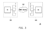
FIG. 3 illustrates an exemplary MIMO system in accordance with the present disclosure. -
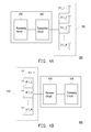
FIG. 4A is a functional block diagram illustrating a transmitter according to an exemplary embodiment. -
FIG. 4B is a functional block diagram illustrating a receiver according to an exemplary embodiment. -
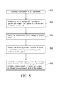
FIG. 5 illustrates a flowchart of a spatial-domain modulation method for multi-antenna system according to one of the exemplary embodiments of the present disclosure. -
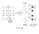
FIG 6A is a schematic diagram illustrating spatial-domain modulation with L= 2 according to one of the exemplary embodiments of the present disclosure. -
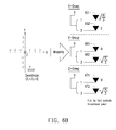
FIG 6B is a schematic diagram illustrating spatial-domain modulation with L = 3 according to one of the exemplary embodiments of the present disclosure. -
FIG. 7 illustrates a flowchart of method for detecting spatial-domain modulation signal for multi-antenna system according to one of the exemplary embodiments of the present disclosure. -
FIG. 8 is a schematic diagram illustrates simulation results of the spatial-domain modulation method with method for detecting spatial-domain modulation signal for multi-antenna system according to one of the exemplary embodiments of the present disclosure. - In this disclosure, 3GPP-like keywords or phrases are used merely as examples to present inventive concepts in accordance with the present disclosure; however, the same concept presented in the disclosure can be applied to any other systems such as IEEE 802.11, IEEE 802.16, WiMAX, and so like by persons of ordinarily skilled in the art.
- A receiver and transmitter in this disclosure could be applied into a control node or an UE. A control node in this disclosure would be referred to as a base station (BS) or an eNB. It should be noted that the references of such are merely exemplary and therefore do not serve as limitations to the type of control nodes as it would be apparent to those skilled in the art that other types of control node could be selected to achieve network control purposes such as an advanced base station (ABS), a base transceiver system (BTS), an access point, a home base station, a relay station, a repeater, an intermediate node, an intermediary, and/or satellite-based communication base stations.
- The control node may also be referred to entities such as a Mobility Management Entity (MME), a Serving Gateway (S-GW), a Packet Data Network Gateway (PDN-GW), a Serving GPRS Support Node (SGSN), a Gateway GPRS Support Node (GGSN), a Mobile Switching Center (MSC), and a Home Subscriber Server (HSS) or a node maintaining a database related to subscriber information.
- The term "user equipment" (UE) in this disclosure could represent various embodiments which for example could include but not limited to a mobile station, an advanced mobile station (AMS), a server, a client, a desktop computer, a laptop computer, a network computer, a workstation, a personal digital assistant (PDA), a tablet personal computer (PC), a scanner, a telephone device, a pager, a camera, a television, a hand-held video game device, a musical device, a wireless sensor, and so like. In some applications, a UE may be a fixed computer device operating in a mobile environment, such as a bus, train, an airplane, a boat, a car, and so forth.
- From the hardware perspective, the receiver may also be referred to as an apparatus including at least but not limited to a receiver circuit, an analog-to-digital (A/D) converter, a processing circuit, one or more antenna units, and optionally a storage medium. The transmitter may also be referred to as an apparatus including at least but not limited to a transmitter circuit, a digital-to-analog (D/A) converter, a processing circuit, one or more antenna units, and optionally a storage medium. The transmitter and the receiver transmit downlink signals and receive uplink signals wirelessly. The receiver may include functional elements to perform operations such as low noise amplifying, impedance matching, frequency mixing, down frequency conversion, filtering, amplifying, and so forth. The transmitter may include function elements to perform operations such as amplifying, impedance matching, frequency mixing, up frequency conversion, filtering, power amplifying, and so forth.
- The processing circuit is configured to process digital signal and to perform procedures related to the proposed method in accordance with exemplary embodiments of the present disclosure. Also, the processing circuit may optionally be coupled to a memory circuit to store programming codes, device configurations, a codebook, buffered or permanent data, and etc... The functions of the processing circuit may be implemented using programmable units such as a micro-processor, a micro-controller, a DSP chips, FPGA, etc. The functions of the processing circuit may also be implemented with separate electronic devices or ICs, and the processing circuit may also be implemented with either hardware or software.
-
FIG. 3 illustrates a MIMO communication system. Referring toFIG. 1 , aMIMO communication system 30 includes atransmitter 300 and areceiver 400. Bothtransmitter 300 and thereceiver 400 could be applied into wireless communication devices. For example, thetransmitter 300 could be applied into a base station or be used in any of the aforementioned control nodes, and thereceiver 400 could be applied into a mobile station or be used in any of the aforementioned user equipments. However, the present disclosure is not limited thereto. Referring toFIG. 3 , thetransmitter 300 can transmit radio signals to thereceiver 400 through aMIMO channel 500. It is noted that, the wireless communication devices including atransmitter 300 could also have a receiver to receive radio signals through aMIMO channel 500. Similarly, the wireless communication devices including areceiver 400 could also have a transmitter to transmit radio signals through aMIMO channel 500. -
FIG. 4A is a functional block diagram illustrating a transmitter according to an exemplary embodiment. Referring toFIG. 4A , atransmitter 300 can be applied in a wireless communication device at a transmitting end, and can include at least anantenna array 310, atransmitter circuit 320 and aprocessing circuit 330, wherein theantenna array 310 may include N antennas 311_1∼311_N.FIG. 4B is a functional block diagram illustrating a transmitter according to an exemplary embodiment. Referring toFIG. 4B , atransmitter 400 can be applied in a wireless communication device at a receiving end, and can include at least anantenna array 410, areceiver circuit 420 and aprocessing circuit 430, wherein theantenna array 410 includes R antennas 411_1∼411_R. Thetransmitter 300 and thereceiver 400 are configured for transmitting signals to another wireless communication device and receiving signals from another wireless communication device respectively. -
FIG. 5 illustrates a flowchart of a spatial-domain modulation method for multi-antenna system according to one of the exemplary embodiments of the present disclosure. Referring toFIG. 4A andFIG. 5 , the spatial-domain modulation method for multi-antenna system starts from step S510, in which theprocessing circuit 330 may receive a bit stream to be transmitted. In the step S520, theprocessing circuit 330 may transfers the bit stream into a plurality of symbols and maps each symbol to L-dimensional coordinate, wherein 1 < L < N. The most trivial example would be the symbol points on the constellation diagrams for in-phase/quadrature (IQ) modulation, in which each symbol is express by a coordinate with L=2 dimensions. For example, the bit stream could be modulated by M-ary quadrature amplitude modulation (QAM). - In the step S530, the
processing circuit 330 divides the antennas 311_1∼311_N into L non-overlapping antenna groups. In the present disclosure, the L-dimension coordinate could be presented by using indices of L active transmit-antennas with one active antenna per antenna group, while the other antennas are muted. In other words, the N transmit antennas are divided into L non-overlapping antenna groups. Each group corresponds to one of the dimensions. - In the step S540, the
processing circuit 330 chooses one activating antenna from the antennas 311_1∼311_N in each of the antenna groups according to the coordinate of the symbols. Simply, in every signaling interval, one antenna per group is activated in accordance to the magnitude of the associated coordinate component. In detail, theprocessing circuit 330 assigns each of the groups to represent the dimension respectively. Also, in according with the groups, theprocessing circuit 330 determines one activating antenna representing each of the dimensions respectively based on the coordinate of the symbols. - In the step S550, the
processing circuit 330 transmits modulated signal by using the activating antenna in each of the antenna groups, wherein the activating antenna in each of the antenna groups are chosen in according with each of the symbols to be transmitted. It is noted that, theprocessing circuit 330 encodes the symbols in according with each of the activating antenna by using a signal modulation scheme .For example, the negative/positive sign of each coordinate component is in indicated by using the polarity of a binary phase shift keying (BPSK) symbol on each activated antenna, but this disclosure is not limited to it. The signal modulation scheme also comprises Quadrature Phase Shift Keying (QPSK), Quadrature Amplitude Modulation (QAM), or any combination thereof. -
FIG. 6A is a diagram illustrating a case in which L=2 by assuming that symbol are extracted from an IQ signal constellation. It is noted that, the extensions to cases with L > 2 are straight forward. Referring toFIG. 6 , in this case, in order to send a 4-bits message on the 16-QAM signal constellation diagram with N=4 transmit-antennas, which are formed into L=2 groups, each group is consisting of two antennas. How the antennas are grouped can be done arbitrarily. Each of the antenna groups corresponds to one dimension of the symbol coordinate; in QAM cases, the two groups can be designated as I-group (for in-phase component) and Q-group (for quadrature component) respectively. Each antenna within a group represents the absolute magnitude of a possible value of the group's correspondent component. In this case, the two antennas in each group respectively represent 1 and 3, since the unnormalized absolute value of any coordinate component in the 16-QAM constellation is either 1 or 3. The antennas in each group are activated or remain muted in accordance to the presence of its associated component value in the message symbol coordinate, so only one antenna per group is activated in a channel use. Furthermore, the sign of each component value (negative or positive) is indicated by applying BPSK signal on each of the active antennas. It is noted that, in the other embodiment, the antennas could be any type of the signal emitter such as light-emitting diodes. -
FIG 6A is a schematic diagram illustrating spatial-domain modulation for L=2 according to one of the exemplary embodiments of the present disclosure. ReferringFIG 5 andFIG 6 , in the step S510, the transmitter would receive a bit stream to be transmitted. For example, the bit stream may include a plurality of bits, such as 01010001. In the step S520, the transmitter may transfer the bit stream 01010001 into a plurality of symbols and maps the symbol as 2-dimensional coordinate,FIG 6A shows that the coordinate of the symbol for the 4-bits information '0101' is (1,-3) on the 16-QAM signal constellation. In the step S530, the transmitter would divide the antennas610∼640_into 2 non-overlapping antenna groups. In the step S540, the transmitter would choose one activating antenna from the antennas 610-640 in each I-group and Q-group according to the coordinate of the symbol '0101'. - In the step S550, the transmitter would transmit modulated signal by using the activating antenna in each of the antenna groups, Since the in-phase component of the coordinate is 1, a positive BPSK symbol is signaled by the
antenna 610 that represents '1' in the I-group. Similarly, the quadrature component of the symbol coordinate is -3, so a negative BPSK symbol is launched by theantenna 640 that represents '3' in Q-group. The remainingantenna 620 andantenna 630 are all muted. Therefore, the power that can be loaded on each active antenna is PT/3, wherein PT is the total available power at the transmitter. -
FIG 6B is a schematic diagram illustrating spatial-domain modulation for L=3 according to one of the exemplary embodiments of the present disclosure. Based on the foregoing description,FIG 6B shows that the coordinate of the symbol for the 6-bits information '010101' is (1,-3,-3) on the signal constellation. Since the X-group component of the coordinate is 1, a positive BPSK symbol is signaled by theantenna 651 that represents '1' in the X-group. Similarly, the Y-group component of the symbol coordinate is -3, so a negative BPSK symbol is launched by theantenna 662 that represents '3' in Y-group. Similarly, the Z-group component of the symbol coordinate is -3, so a negative BPSK symbol is launched by theantenna 672 that represents '3' in Z-group. The remaining antennas are all muted. Therefore, the power that can be loaded on each active antenna is PT/2, wherein PT is the total available power at the transmitter. - Moreover, the achievable rate of the spatial-domain modulation in the present disclosure could be represented as equation (1).

- A method of detecting a spatial-domain modulation signal would be discussed according to another exemplary embodiment of the present disclosure. This embodiment corresponds to a detection method. In the foregoing embodiment, it is assumed that the antennas are divided into L groups and only one antenna is activated in each group. Therefore, the detection in the present disclosure could be carried out in a "group-by-group" sequential manner.
- Mathematically, the signal model for the spatial-domain in MIMO system could be written as equation (2).

FIG. 7 illustrates a flowchart of a spatial-domain modulation method for multi-antenna system according to a first exemplary embodiment. Referring toFIG. 4B andFIG. 7 together, the spatial-domain modulation method for multi-antenna system would stars from step S710, in which theprocessing circuit 430 receives a signal via theantenna array 410, wherein elements of a received signal vector are grouped into L groups responding to the spatial-domain method. For example, the method is explained based on the cases with L=2, where the transmit antennas have been divided into I-group and Q-group, as the example elucidated for the first embodiment, in which the received signal vector x = [ XI XQ]T is consisted of two (0.5*N)-by-1 vectors XI (I-group) and XQ (Q-group), and each of vectors XI and XQ has only one non-zero element. In detail, vector XI= [ XI,1 XI,2 ... XI,N/2]T and vector XQ= [ XQ,1 XQ,2...XQ,N/2]T. The elements of the vector XI and the vector XQ are equal to 0,√ (PT/2) or -√ (PT/2). It is noted that, there is only one element in vector XI and the vector XQ is √ (PT/2) or -√ (PT/2). - In the step S720, the
processing circuit 430 selects a target group to obtain a plurality of possible vectors by setting the elements equal to 0 expect for the elements of the possible vectors in the target group. In the step S730, theprocessing circuit 430 calculates Euclidean distance between the possible vectors and the received signal vector and selecting K candidate vectors having the minimum Euclidean distance, wherein K < N. - For example, in the case of L=2, the
processing circuit 430 could select vector XI as the target group and the detecting method of the present disclosure commences by finding K candidate vectors from the N/2 possible value of XI that results in minimum Euclidean distance between the received signal vector y and the possible vectors Xpo with the elements of vector XQ replaced by a (0.5*N)-by-1 zero-vector , the formula for calculating Euclidean distance could be written as equation (3).
In the other hand, theprocessing circuit 430 could select vector XQ as the target group, and the formula for calculating Euclidean distance could be written as equation (4).
- In the step S740, the
processing circuit 430 may select another group as the new target group from the groups never been as the target group in order to obtain new possible vectors from the first candidate vectors, wherein the elements of the new possible vectors on the dimensions never been as the target group are 0. In the step S750, theprocessing circuit 430 calculates Euclidean distance between the new possible vectors and the received signal vector and selecting the new candidate vectors having the minimum Euclidean distance. In the step S760, theprocessing circuit 430 repeats the two foregoing steps until all the L dimensions have been as the target group for obtaining a detected result vector from the candidate vectors. - For example, in the case of L=2, for the detecting method of the present disclosure, based on each of the K candidate vectors, we search and identify the minimum resultant Euclidean distance between y and x, in which x is constructed by stacking the k-th (k = 1...K) candidate vectors with the j-th (j = 1...N) candidate vectors of XQ. That is,

- Finally, the detected result signal vector would be detected as Xest=[ XI,k* XQ,j*]T. The extension to the cases with L > 2 is straightforward.
-
FIG. 8 is a schematic diagram which illustrates simulation results of the spatial-domain modulation method which uses the method for detecting spatial-domain modulation signal for multi-antenna system according to an exemplary embodiment. By modeling MIMO channel as a R-by-N matrix with independent and identically distributed (iid) zero-mean complex Gaussian entries, the performances in terms of symbol error rate (SER) could derived as illustrated inFIG 8 . For a MIMO system with N=128 transmit-antennas and R=16 receive-antennas is considered, the system is able to send 14-bits information per channel by the spatial-domain modulation method in the present disclosure. To reach the same data rate under the identical system configurations, SM requires 128-QAM modulation to encode the bit stream to be transmitted. Also at least three antennas have to be activated with GSSK for the same data rate. It could be observed that the spatial-domain modulation method in the present disclosure has better SER performance than both SM and GSSK, even if the reduced-complexity detecting method in the present disclosure is applied. Remarkably, detecting the received signal by ML performance could be achieved by setting K=32, notwithstanding a huge complexity reduction of nearly 75%. - In the disclosure and all of the embodiments, no element, act, or instruction used in the description of the present application should be construed as absolutely critical or essential to the present disclosure unless explicitly described as such. Also, as used herein, each of the indefinite articles "a" and "an" is intended to exclude more than one item. If only one item is intended, the terms "a single" or similar languages could be used. Furthermore, the terms "any of" followed by a listing of a plurality of items and/or a plurality of categories of items, as used herein, are intended to include "any of", "any combination of", "any multiple of", and/or "any combination of multiples of the items and/or the categories of items, individually or in conjunction with other items and/or other categories of items. Further, as used herein, the term "set" is intended to include any number of items, including zero. Further, as used herein, the term "number" is intended to include any number, including zero.
Claims (11)
- A data modulation method, adapted to a transmitter (320) having an antenna array including N antennas (310) in a multi-antenna communication system, wherein N>1, and the method comprising:receiving a plurality of symbols to be transmitted (S520);mapping each of the symbols as a L-dimensional coordinate, wherein 1 < L < N; (S520)dividing the N antennas into L non-overlapping antenna groups; (S530)choosing one activating antenna from the antennas in each of the antenna groups according to the coordinate of the symbols; (S540) andtransmitting modulated signal by using the chosen activating antenna in each of the antenna groups, wherein a signal modulation scheme used on each of the L chosen activating antennas is determined in accordance to the L-dimensional coordinate (S550).
- The data modulation method of claim 1, wherein before receiving the symbols to be transmitted, claim 1 further comprises:receiving a bit stream to be transmitted; (S510) andtransferring the bit stream into the symbols. (S520)
- The data modulation method of claim 1, wherein mapping the symbol as L-dimensional coordinate comprises:modulating the symbols by using M-ary Quadrature Amplitude Modulation.
- The data modulation method of claim 1, wherein the signal modulation scheme comprises Binary Phase Shift Keying (BPSK), or Quadrature Phase Shift Keying (QPSK), or Quadrature Amplitude Modulation (QAM), or any combination thereof.
- The data modulation method of claim 1, wherein choosing one activating antenna from the antennas in each of the antenna groups according to the coordinate of the symbols comprise:assigning the L antenna groups to respectively represent the L dimensions of the coordinate of the symbols; andbased on the coordinate of the symbols, determining one activating antenna in each of the antenna groups according to the coordinate value in the dimension that the antenna groups corresponding to.
- A transmitter (320) using data modulation method in a multi-antenna system, and the transmitter (320) comprising an antenna array having N antennas, a communication unit (310), and a processing circuit (330) is configured for executing:receiving a plurality of symbols to be transmitted; (S520)mapping the symbols as L-dimensional coordinate, wherein 1 < L < N;dividing the antennas into L non-overlapping antenna groups; (S530)choosing one activating antenna from the antennas in each of the antenna groups according to the coordinate of the symbols (S540); andtransmitting modulated signal by using the chosen activating antenna in each of the antenna groups, wherein a signal modulation scheme used on each of the L chosen activating antennas is determined in accordance to the L-dimensional coordinate (S550).
- The transmitter of claim 6, wherein the processing circuit is configured for receiving the symbols to be transmitted further comprises:receiving a bit stream to be transmitted (S510); andtransferring the bit stream into the symbols (S520).
- The transmitter of claim 6, wherein the processing circuit is configured for mapping the symbol as L-dimensional coordinate comprises:modulating the symbols by using M-ary Quadrature Amplitude Modulation.
- The transmitter of claim 6, wherein the signal modulation scheme comprises Binary Phase Shift Keying (BPSK), or Quadrature Phase Shift Keying (QPSK), or Quadrature Amplitude Modulation (QAM), or any combination thereof.
- The transmitter of claim 6, wherein the processing circuit (340) is configured for choosing one activating antenna from the antennas in each of the antenna groups according to the coordinate of the symbols comprise:assigning the L antenna groups to respectively represent the L dimensions of the coordinate of the symbols; andbased on the coordinate of the symbols, determining one activating antenna in each of the antenna groups according to the coordinate value in the dimension that the antenna groups corresponding to.
- The transmitter of claim 6, wherein each of the antennas could be one of a loudspeaker, an ultrasound transmitter or a multiple light emitting diode.
Applications Claiming Priority (2)
| Application Number | Priority Date | Filing Date | Title |
|---|---|---|---|
| US201261693340P | 2012-08-27 | 2012-08-27 | |
| US13/887,380 US8953712B2 (en) | 2012-08-27 | 2013-05-06 | Method for data modulation and transmitter using the same |
Publications (3)
| Publication Number | Publication Date |
|---|---|
| EP2704334A2 true EP2704334A2 (en) | 2014-03-05 |
| EP2704334A3 EP2704334A3 (en) | 2017-08-02 |
| EP2704334B1 EP2704334B1 (en) | 2018-05-16 |
Family
ID=49028911
Family Applications (1)
| Application Number | Title | Priority Date | Filing Date |
|---|---|---|---|
| EP13180960.0A Active EP2704334B1 (en) | 2012-08-27 | 2013-08-20 | Method for spatial-domain data modulation and transmitter using the same |
Country Status (4)
| Country | Link |
|---|---|
| US (1) | US8953712B2 (en) |
| EP (1) | EP2704334B1 (en) |
| CN (1) | CN103634035B (en) |
| TW (1) | TWI482446B (en) |
Families Citing this family (6)
| Publication number | Priority date | Publication date | Assignee | Title |
|---|---|---|---|---|
| US9313076B2 (en) | 2013-07-11 | 2016-04-12 | Industrial Technology Research Institute | Antenna modulation method applicable to wireless transmitter and transmitter using the same |
| KR101573827B1 (en) * | 2014-11-17 | 2015-12-02 | 한국항공대학교산학협력단 | Activated antenna detection method in spatial modulation system |
| US20170288933A1 (en) * | 2016-03-30 | 2017-10-05 | Intel IP Corporation | Wireless signal receiver |
| CN109547077B (en) * | 2019-01-22 | 2020-10-13 | 重庆京东方智慧电子系统有限公司 | Signal transmission method, signal reception method, communication device and storage medium |
| CN109889242B (en) * | 2019-01-24 | 2021-11-12 | 东华大学 | Central circulation weight generalized space shift keying modulation device and modulation method |
| CN112702732B (en) * | 2020-12-18 | 2022-09-16 | 西安邮电大学 | Generalized spatial modulation secure transmission method based on low-complexity additive noise |
Family Cites Families (9)
| Publication number | Priority date | Publication date | Assignee | Title |
|---|---|---|---|---|
| US6542556B1 (en) * | 2000-03-31 | 2003-04-01 | Nokia Mobile Phones Ltd. | Space-time code for multiple antenna transmission |
| US20020094783A1 (en) * | 2000-11-28 | 2002-07-18 | Yawgeng Chau | Space shift keying modulation |
| US7505788B1 (en) | 2002-12-09 | 2009-03-17 | Marvell International, Ltd. | Spatial multiplexing with antenna and constellation selection for correlated MIMO fading channels |
| WO2006002550A1 (en) * | 2004-07-07 | 2006-01-12 | Nortel Networks Limited | System and method for mapping symbols for mimo transmission |
| KR100891448B1 (en) | 2005-08-04 | 2009-04-01 | 삼성전자주식회사 | Spatial Multiplexing Detection Apparatus and Method in Multi-antenna System |
| US7657244B2 (en) | 2005-10-27 | 2010-02-02 | Samsung Electronics Co., Ltd. | Methods of antenna selection for downlink MIMO-OFDM transmission over spatial correlated channels |
| KR101009774B1 (en) | 2006-07-11 | 2011-01-19 | 더 유니버시티 코트 오브 더 유니버시티 오브 에딘버그 | Spatial Modulation in Multiple Input and Output Systems and Transceivers Using the Same |
| CN101521514B (en) * | 2008-10-13 | 2012-01-18 | 重庆无线绿洲通信技术有限公司 | Q-ary coded modulation method combined with repeat accumulate code and device thereof |
| GB2496379A (en) * | 2011-11-04 | 2013-05-15 | Univ Edinburgh | A freespace optical communication system which exploits the rolling shutter mechanism of a CMOS camera |
-
2013
- 2013-05-06 US US13/887,380 patent/US8953712B2/en active Active
- 2013-08-06 TW TW102128115A patent/TWI482446B/en active
- 2013-08-20 EP EP13180960.0A patent/EP2704334B1/en active Active
- 2013-08-23 CN CN201310373320.7A patent/CN103634035B/en active Active
Non-Patent Citations (1)
| Title |
|---|
| None |
Also Published As
| Publication number | Publication date |
|---|---|
| CN103634035B (en) | 2016-12-28 |
| EP2704334B1 (en) | 2018-05-16 |
| TWI482446B (en) | 2015-04-21 |
| TW201409962A (en) | 2014-03-01 |
| EP2704334A3 (en) | 2017-08-02 |
| CN103634035A (en) | 2014-03-12 |
| US20140056383A1 (en) | 2014-02-27 |
| US8953712B2 (en) | 2015-02-10 |
Similar Documents
| Publication | Publication Date | Title |
|---|---|---|
| US12587264B2 (en) | Method for transmitting and receiving data in cooperative communication system, and cooperative communication method | |
| EP2704334B1 (en) | Method for spatial-domain data modulation and transmitter using the same | |
| JP5453458B2 (en) | Multiple input / output transmission beam forming method and apparatus | |
| KR102334011B1 (en) | Method and apparatus for limited feedback based on machine learning in wireless communication system | |
| US10547487B1 (en) | Integer non-uniform constellation for high-order QAM | |
| US11258649B2 (en) | Transmitter and receiver communication apparatus for non-coherent communication | |
| KR20120096569A (en) | Method and apparatus for processing feedback in a wireless communication system | |
| US8649455B2 (en) | Multiple input multiple output communication system and communication method of adaptably transforming codebook | |
| EP2340620A2 (en) | Method of controlling interference in a wireless communication system having multiple antennas | |
| EP2824882B1 (en) | Antenna modulation method applicable to wireless transmitter and transmitter using the same | |
| CN108631842A (en) | A method, apparatus and electronic device for determining beam reciprocity of a device | |
| CN102710394A (en) | Spatial modulation method based on transmitting antenna selection for MIMO (Multi-Input Multi-Output) system | |
| US11855730B2 (en) | Apparatus and method for reconstructing downlink channel in wireless communication system | |
| JP2011501606A (en) | Multi-antenna communication method and system | |
| WO2012157393A1 (en) | Base station, mobile station, control program and integrated circuit | |
| KR102206549B1 (en) | Transmitting apparus and precoding method thereof | |
| CN113841344A (en) | Spatial multiplexing method and apparatus using polarization in multi-beam system | |
| Jiang et al. | Ris-enhanced semantic image transmission based on reinforcement learning | |
| KR102309631B1 (en) | Spatial multiplexing method and appatatus using polarization in multiple beams system | |
| KR101645996B1 (en) | Ofdm symbol transmiting using espar antenna in beamspace mimo system | |
| Bhat et al. | Load modulated arrays using channel modulation with RF mirrors | |
| WO2021151980A1 (en) | Finite resolution decomposition of a matrix and matrix-vector multiplication | |
| Kuo | SCRAD modulation: high data rate space shift keying scheme permitting reduced-complexity detector | |
| Wei et al. | High-order Direct Antenna Modulation via Passive Reconfigurable Intelligent Surface | |
| WO2026017084A1 (en) | Modulation scheme determination method and apparatus, demodulation scheme determination method and apparatus, and device |
Legal Events
| Date | Code | Title | Description |
|---|---|---|---|
| AK | Designated contracting states |
Kind code of ref document: A2 Designated state(s): AL AT BE BG CH CY CZ DE DK EE ES FI FR GB GR HR HU IE IS IT LI LT LU LV MC MK MT NL NO PL PT RO RS SE SI SK SM TR |
|
| AX | Request for extension of the european patent |
Extension state: BA ME |
|
| PUAI | Public reference made under article 153(3) epc to a published international application that has entered the european phase |
Free format text: ORIGINAL CODE: 0009012 |
|
| PUAL | Search report despatched |
Free format text: ORIGINAL CODE: 0009013 |
|
| AK | Designated contracting states |
Kind code of ref document: A3 Designated state(s): AL AT BE BG CH CY CZ DE DK EE ES FI FR GB GR HR HU IE IS IT LI LT LU LV MC MK MT NL NO PL PT RO RS SE SI SK SM TR |
|
| AX | Request for extension of the european patent |
Extension state: BA ME |
|
| RIC1 | Information provided on ipc code assigned before grant |
Ipc: H04B 7/06 20060101AFI20170629BHEP Ipc: H04B 7/04 20170101ALI20170629BHEP |
|
| STAA | Information on the status of an ep patent application or granted ep patent |
Free format text: STATUS: REQUEST FOR EXAMINATION WAS MADE |
|
| 17P | Request for examination filed |
Effective date: 20171115 |
|
| RBV | Designated contracting states (corrected) |
Designated state(s): AL AT BE BG CH CY CZ DE DK EE ES FI FR GB GR HR HU IE IS IT LI LT LU LV MC MK MT NL NO PL PT RO RS SE SI SK SM TR |
|
| GRAP | Despatch of communication of intention to grant a patent |
Free format text: ORIGINAL CODE: EPIDOSNIGR1 |
|
| STAA | Information on the status of an ep patent application or granted ep patent |
Free format text: STATUS: GRANT OF PATENT IS INTENDED |
|
| INTG | Intention to grant announced |
Effective date: 20180108 |
|
| GRAS | Grant fee paid |
Free format text: ORIGINAL CODE: EPIDOSNIGR3 |
|
| GRAA | (expected) grant |
Free format text: ORIGINAL CODE: 0009210 |
|
| STAA | Information on the status of an ep patent application or granted ep patent |
Free format text: STATUS: THE PATENT HAS BEEN GRANTED |
|
| AK | Designated contracting states |
Kind code of ref document: B1 Designated state(s): AL AT BE BG CH CY CZ DE DK EE ES FI FR GB GR HR HU IE IS IT LI LT LU LV MC MK MT NL NO PL PT RO RS SE SI SK SM TR |
|
| REG | Reference to a national code |
Ref country code: GB Ref legal event code: FG4D |
|
| REG | Reference to a national code |
Ref country code: CH Ref legal event code: EP |
|
| REG | Reference to a national code |
Ref country code: IE Ref legal event code: FG4D |
|
| REG | Reference to a national code |
Ref country code: DE Ref legal event code: R096 Ref document number: 602013037451 Country of ref document: DE |
|
| REG | Reference to a national code |
Ref country code: AT Ref legal event code: REF Ref document number: 1000481 Country of ref document: AT Kind code of ref document: T Effective date: 20180615 |
|
| REG | Reference to a national code |
Ref country code: FR Ref legal event code: PLFP Year of fee payment: 6 |
|
| REG | Reference to a national code |
Ref country code: NL Ref legal event code: FP |
|
| REG | Reference to a national code |
Ref country code: LT Ref legal event code: MG4D |
|
| PG25 | Lapsed in a contracting state [announced via postgrant information from national office to epo] |
Ref country code: FI Free format text: LAPSE BECAUSE OF FAILURE TO SUBMIT A TRANSLATION OF THE DESCRIPTION OR TO PAY THE FEE WITHIN THE PRESCRIBED TIME-LIMIT Effective date: 20180516 Ref country code: BG Free format text: LAPSE BECAUSE OF FAILURE TO SUBMIT A TRANSLATION OF THE DESCRIPTION OR TO PAY THE FEE WITHIN THE PRESCRIBED TIME-LIMIT Effective date: 20180816 Ref country code: NO Free format text: LAPSE BECAUSE OF FAILURE TO SUBMIT A TRANSLATION OF THE DESCRIPTION OR TO PAY THE FEE WITHIN THE PRESCRIBED TIME-LIMIT Effective date: 20180816 Ref country code: LT Free format text: LAPSE BECAUSE OF FAILURE TO SUBMIT A TRANSLATION OF THE DESCRIPTION OR TO PAY THE FEE WITHIN THE PRESCRIBED TIME-LIMIT Effective date: 20180516 Ref country code: ES Free format text: LAPSE BECAUSE OF FAILURE TO SUBMIT A TRANSLATION OF THE DESCRIPTION OR TO PAY THE FEE WITHIN THE PRESCRIBED TIME-LIMIT Effective date: 20180516 Ref country code: SE Free format text: LAPSE BECAUSE OF FAILURE TO SUBMIT A TRANSLATION OF THE DESCRIPTION OR TO PAY THE FEE WITHIN THE PRESCRIBED TIME-LIMIT Effective date: 20180516 |
|
| PG25 | Lapsed in a contracting state [announced via postgrant information from national office to epo] |
Ref country code: GR Free format text: LAPSE BECAUSE OF FAILURE TO SUBMIT A TRANSLATION OF THE DESCRIPTION OR TO PAY THE FEE WITHIN THE PRESCRIBED TIME-LIMIT Effective date: 20180817 Ref country code: HR Free format text: LAPSE BECAUSE OF FAILURE TO SUBMIT A TRANSLATION OF THE DESCRIPTION OR TO PAY THE FEE WITHIN THE PRESCRIBED TIME-LIMIT Effective date: 20180516 Ref country code: RS Free format text: LAPSE BECAUSE OF FAILURE TO SUBMIT A TRANSLATION OF THE DESCRIPTION OR TO PAY THE FEE WITHIN THE PRESCRIBED TIME-LIMIT Effective date: 20180516 Ref country code: LV Free format text: LAPSE BECAUSE OF FAILURE TO SUBMIT A TRANSLATION OF THE DESCRIPTION OR TO PAY THE FEE WITHIN THE PRESCRIBED TIME-LIMIT Effective date: 20180516 |
|
| REG | Reference to a national code |
Ref country code: AT Ref legal event code: MK05 Ref document number: 1000481 Country of ref document: AT Kind code of ref document: T Effective date: 20180516 |
|
| PG25 | Lapsed in a contracting state [announced via postgrant information from national office to epo] |
Ref country code: RO Free format text: LAPSE BECAUSE OF FAILURE TO SUBMIT A TRANSLATION OF THE DESCRIPTION OR TO PAY THE FEE WITHIN THE PRESCRIBED TIME-LIMIT Effective date: 20180516 Ref country code: EE Free format text: LAPSE BECAUSE OF FAILURE TO SUBMIT A TRANSLATION OF THE DESCRIPTION OR TO PAY THE FEE WITHIN THE PRESCRIBED TIME-LIMIT Effective date: 20180516 Ref country code: PL Free format text: LAPSE BECAUSE OF FAILURE TO SUBMIT A TRANSLATION OF THE DESCRIPTION OR TO PAY THE FEE WITHIN THE PRESCRIBED TIME-LIMIT Effective date: 20180516 Ref country code: DK Free format text: LAPSE BECAUSE OF FAILURE TO SUBMIT A TRANSLATION OF THE DESCRIPTION OR TO PAY THE FEE WITHIN THE PRESCRIBED TIME-LIMIT Effective date: 20180516 Ref country code: AT Free format text: LAPSE BECAUSE OF FAILURE TO SUBMIT A TRANSLATION OF THE DESCRIPTION OR TO PAY THE FEE WITHIN THE PRESCRIBED TIME-LIMIT Effective date: 20180516 Ref country code: SK Free format text: LAPSE BECAUSE OF FAILURE TO SUBMIT A TRANSLATION OF THE DESCRIPTION OR TO PAY THE FEE WITHIN THE PRESCRIBED TIME-LIMIT Effective date: 20180516 Ref country code: CZ Free format text: LAPSE BECAUSE OF FAILURE TO SUBMIT A TRANSLATION OF THE DESCRIPTION OR TO PAY THE FEE WITHIN THE PRESCRIBED TIME-LIMIT Effective date: 20180516 |
|
| REG | Reference to a national code |
Ref country code: DE Ref legal event code: R097 Ref document number: 602013037451 Country of ref document: DE |
|
| PG25 | Lapsed in a contracting state [announced via postgrant information from national office to epo] |
Ref country code: SM Free format text: LAPSE BECAUSE OF FAILURE TO SUBMIT A TRANSLATION OF THE DESCRIPTION OR TO PAY THE FEE WITHIN THE PRESCRIBED TIME-LIMIT Effective date: 20180516 |
|
| PLBE | No opposition filed within time limit |
Free format text: ORIGINAL CODE: 0009261 |
|
| STAA | Information on the status of an ep patent application or granted ep patent |
Free format text: STATUS: NO OPPOSITION FILED WITHIN TIME LIMIT |
|
| PG25 | Lapsed in a contracting state [announced via postgrant information from national office to epo] |
Ref country code: MC Free format text: LAPSE BECAUSE OF FAILURE TO SUBMIT A TRANSLATION OF THE DESCRIPTION OR TO PAY THE FEE WITHIN THE PRESCRIBED TIME-LIMIT Effective date: 20180516 |
|
| REG | Reference to a national code |
Ref country code: CH Ref legal event code: PL |
|
| 26N | No opposition filed |
Effective date: 20190219 |
|
| PG25 | Lapsed in a contracting state [announced via postgrant information from national office to epo] |
Ref country code: CH Free format text: LAPSE BECAUSE OF NON-PAYMENT OF DUE FEES Effective date: 20180831 Ref country code: LI Free format text: LAPSE BECAUSE OF NON-PAYMENT OF DUE FEES Effective date: 20180831 Ref country code: LU Free format text: LAPSE BECAUSE OF NON-PAYMENT OF DUE FEES Effective date: 20180820 |
|
| REG | Reference to a national code |
Ref country code: BE Ref legal event code: MM Effective date: 20180831 |
|
| REG | Reference to a national code |
Ref country code: IE Ref legal event code: MM4A |
|
| PG25 | Lapsed in a contracting state [announced via postgrant information from national office to epo] |
Ref country code: SI Free format text: LAPSE BECAUSE OF FAILURE TO SUBMIT A TRANSLATION OF THE DESCRIPTION OR TO PAY THE FEE WITHIN THE PRESCRIBED TIME-LIMIT Effective date: 20180516 |
|
| PG25 | Lapsed in a contracting state [announced via postgrant information from national office to epo] |
Ref country code: IE Free format text: LAPSE BECAUSE OF NON-PAYMENT OF DUE FEES Effective date: 20180820 |
|
| PG25 | Lapsed in a contracting state [announced via postgrant information from national office to epo] |
Ref country code: BE Free format text: LAPSE BECAUSE OF NON-PAYMENT OF DUE FEES Effective date: 20180831 |
|
| PG25 | Lapsed in a contracting state [announced via postgrant information from national office to epo] |
Ref country code: AL Free format text: LAPSE BECAUSE OF FAILURE TO SUBMIT A TRANSLATION OF THE DESCRIPTION OR TO PAY THE FEE WITHIN THE PRESCRIBED TIME-LIMIT Effective date: 20180516 |
|
| PG25 | Lapsed in a contracting state [announced via postgrant information from national office to epo] |
Ref country code: MT Free format text: LAPSE BECAUSE OF NON-PAYMENT OF DUE FEES Effective date: 20180820 |
|
| PG25 | Lapsed in a contracting state [announced via postgrant information from national office to epo] |
Ref country code: TR Free format text: LAPSE BECAUSE OF FAILURE TO SUBMIT A TRANSLATION OF THE DESCRIPTION OR TO PAY THE FEE WITHIN THE PRESCRIBED TIME-LIMIT Effective date: 20180516 |
|
| PG25 | Lapsed in a contracting state [announced via postgrant information from national office to epo] |
Ref country code: HU Free format text: LAPSE BECAUSE OF FAILURE TO SUBMIT A TRANSLATION OF THE DESCRIPTION OR TO PAY THE FEE WITHIN THE PRESCRIBED TIME-LIMIT; INVALID AB INITIO Effective date: 20130820 Ref country code: PT Free format text: LAPSE BECAUSE OF FAILURE TO SUBMIT A TRANSLATION OF THE DESCRIPTION OR TO PAY THE FEE WITHIN THE PRESCRIBED TIME-LIMIT Effective date: 20180516 |
|
| PG25 | Lapsed in a contracting state [announced via postgrant information from national office to epo] |
Ref country code: MK Free format text: LAPSE BECAUSE OF NON-PAYMENT OF DUE FEES Effective date: 20180516 Ref country code: CY Free format text: LAPSE BECAUSE OF FAILURE TO SUBMIT A TRANSLATION OF THE DESCRIPTION OR TO PAY THE FEE WITHIN THE PRESCRIBED TIME-LIMIT Effective date: 20180516 |
|
| PG25 | Lapsed in a contracting state [announced via postgrant information from national office to epo] |
Ref country code: IS Free format text: LAPSE BECAUSE OF FAILURE TO SUBMIT A TRANSLATION OF THE DESCRIPTION OR TO PAY THE FEE WITHIN THE PRESCRIBED TIME-LIMIT Effective date: 20180916 |
|
| PGFP | Annual fee paid to national office [announced via postgrant information from national office to epo] |
Ref country code: NL Payment date: 20250826 Year of fee payment: 13 |
|
| PGFP | Annual fee paid to national office [announced via postgrant information from national office to epo] |
Ref country code: DE Payment date: 20250827 Year of fee payment: 13 |
|
| PGFP | Annual fee paid to national office [announced via postgrant information from national office to epo] |
Ref country code: IT Payment date: 20250820 Year of fee payment: 13 |
|
| PGFP | Annual fee paid to national office [announced via postgrant information from national office to epo] |
Ref country code: GB Payment date: 20250827 Year of fee payment: 13 |
|
| PGFP | Annual fee paid to national office [announced via postgrant information from national office to epo] |
Ref country code: FR Payment date: 20250825 Year of fee payment: 13 |