EP2704290A2 - Vehicle information control device with load management function - Google Patents
Vehicle information control device with load management function Download PDFInfo
- Publication number
- EP2704290A2 EP2704290A2 EP13181078.0A EP13181078A EP2704290A2 EP 2704290 A2 EP2704290 A2 EP 2704290A2 EP 13181078 A EP13181078 A EP 13181078A EP 2704290 A2 EP2704290 A2 EP 2704290A2
- Authority
- EP
- European Patent Office
- Prior art keywords
- apparatuses
- vehicle
- vehicles
- load
- priorities
- Prior art date
- Legal status (The legal status is an assumption and is not a legal conclusion. Google has not performed a legal analysis and makes no representation as to the accuracy of the status listed.)
- Granted
Links
Images


Classifications
-
- B—PERFORMING OPERATIONS; TRANSPORTING
- B60—VEHICLES IN GENERAL
- B60L—PROPULSION OF ELECTRICALLY-PROPELLED VEHICLES; SUPPLYING ELECTRIC POWER FOR AUXILIARY EQUIPMENT OF ELECTRICALLY-PROPELLED VEHICLES; ELECTRODYNAMIC BRAKE SYSTEMS FOR VEHICLES IN GENERAL; MAGNETIC SUSPENSION OR LEVITATION FOR VEHICLES; MONITORING OPERATING VARIABLES OF ELECTRICALLY-PROPELLED VEHICLES; ELECTRIC SAFETY DEVICES FOR ELECTRICALLY-PROPELLED VEHICLES
- B60L50/00—Electric propulsion with power supplied within the vehicle
- B60L50/50—Electric propulsion with power supplied within the vehicle using propulsion power supplied by batteries or fuel cells
-
- H—ELECTRICITY
- H02—GENERATION; CONVERSION OR DISTRIBUTION OF ELECTRIC POWER
- H02J—ELECTRIC POWER NETWORKS; CIRCUIT ARRANGEMENTS OR SYSTEMS FOR SUPPLYING OR DISTRIBUTING ELECTRIC POWER; SYSTEMS FOR STORING ELECTRIC ENERGY
- H02J7/00—Circuit arrangements for charging or discharging batteries or for supplying loads from batteries
-
- B—PERFORMING OPERATIONS; TRANSPORTING
- B60—VEHICLES IN GENERAL
- B60L—PROPULSION OF ELECTRICALLY-PROPELLED VEHICLES; SUPPLYING ELECTRIC POWER FOR AUXILIARY EQUIPMENT OF ELECTRICALLY-PROPELLED VEHICLES; ELECTRODYNAMIC BRAKE SYSTEMS FOR VEHICLES IN GENERAL; MAGNETIC SUSPENSION OR LEVITATION FOR VEHICLES; MONITORING OPERATING VARIABLES OF ELECTRICALLY-PROPELLED VEHICLES; ELECTRIC SAFETY DEVICES FOR ELECTRICALLY-PROPELLED VEHICLES
- B60L1/00—Supplying electric power to auxiliary equipment of vehicles
- B60L1/02—Supplying electric power to auxiliary equipment of vehicles to electric heating circuits
- B60L1/04—Supplying electric power to auxiliary equipment of vehicles to electric heating circuits fed by the power supply line
- B60L1/10—Supplying electric power to auxiliary equipment of vehicles to electric heating circuits fed by the power supply line with provision for using different supplies
- B60L1/12—Methods and devices for control or regulation
-
- B—PERFORMING OPERATIONS; TRANSPORTING
- B60—VEHICLES IN GENERAL
- B60L—PROPULSION OF ELECTRICALLY-PROPELLED VEHICLES; SUPPLYING ELECTRIC POWER FOR AUXILIARY EQUIPMENT OF ELECTRICALLY-PROPELLED VEHICLES; ELECTRODYNAMIC BRAKE SYSTEMS FOR VEHICLES IN GENERAL; MAGNETIC SUSPENSION OR LEVITATION FOR VEHICLES; MONITORING OPERATING VARIABLES OF ELECTRICALLY-PROPELLED VEHICLES; ELECTRIC SAFETY DEVICES FOR ELECTRICALLY-PROPELLED VEHICLES
- B60L15/00—Methods, circuits, or devices for controlling the traction-motor speed of electrically-propelled vehicles
- B60L15/20—Methods, circuits, or devices for controlling the traction-motor speed of electrically-propelled vehicles for control of the vehicle or its driving motor to achieve a desired performance, e.g. speed, torque, programmed variation of speed
- B60L15/2045—Methods, circuits, or devices for controlling the traction-motor speed of electrically-propelled vehicles for control of the vehicle or its driving motor to achieve a desired performance, e.g. speed, torque, programmed variation of speed for optimising the use of energy
-
- H—ELECTRICITY
- H02—GENERATION; CONVERSION OR DISTRIBUTION OF ELECTRIC POWER
- H02J—ELECTRIC POWER NETWORKS; CIRCUIT ARRANGEMENTS OR SYSTEMS FOR SUPPLYING OR DISTRIBUTING ELECTRIC POWER; SYSTEMS FOR STORING ELECTRIC ENERGY
- H02J2105/00—Networks for supplying or distributing electric power characterised by their spatial reach or by the load
- H02J2105/30—Networks for supplying or distributing electric power characterised by their spatial reach or by the load the load networks being external to vehicles, i.e. exchanging power with vehicles
-
- H—ELECTRICITY
- H02—GENERATION; CONVERSION OR DISTRIBUTION OF ELECTRIC POWER
- H02J—ELECTRIC POWER NETWORKS; CIRCUIT ARRANGEMENTS OR SYSTEMS FOR SUPPLYING OR DISTRIBUTING ELECTRIC POWER; SYSTEMS FOR STORING ELECTRIC ENERGY
- H02J4/00—Circuit arrangements for mains or distribution networks not specified as AC or DC; Circuit arrangements for mains or distribution networks combining AC and DC sections or sub-networks
-
- Y—GENERAL TAGGING OF NEW TECHNOLOGICAL DEVELOPMENTS; GENERAL TAGGING OF CROSS-SECTIONAL TECHNOLOGIES SPANNING OVER SEVERAL SECTIONS OF THE IPC; TECHNICAL SUBJECTS COVERED BY FORMER USPC CROSS-REFERENCE ART COLLECTIONS [XRACs] AND DIGESTS
- Y02—TECHNOLOGIES OR APPLICATIONS FOR MITIGATION OR ADAPTATION AGAINST CLIMATE CHANGE
- Y02T—CLIMATE CHANGE MITIGATION TECHNOLOGIES RELATED TO TRANSPORTATION
- Y02T10/00—Road transport of goods or passengers
- Y02T10/60—Other road transportation technologies with climate change mitigation effect
- Y02T10/64—Electric machine technologies in electromobility
-
- Y—GENERAL TAGGING OF NEW TECHNOLOGICAL DEVELOPMENTS; GENERAL TAGGING OF CROSS-SECTIONAL TECHNOLOGIES SPANNING OVER SEVERAL SECTIONS OF THE IPC; TECHNICAL SUBJECTS COVERED BY FORMER USPC CROSS-REFERENCE ART COLLECTIONS [XRACs] AND DIGESTS
- Y02—TECHNOLOGIES OR APPLICATIONS FOR MITIGATION OR ADAPTATION AGAINST CLIMATE CHANGE
- Y02T—CLIMATE CHANGE MITIGATION TECHNOLOGIES RELATED TO TRANSPORTATION
- Y02T10/00—Road transport of goods or passengers
- Y02T10/60—Other road transportation technologies with climate change mitigation effect
- Y02T10/72—Electric energy management in electromobility
Definitions
- the present invention relates to a vehicle information control device with a load management function.
- Configurations of apparatuses mounted on vehicles have changed in various ways with an advance in the computerization of the vehicles. It is difficult to provide each apparatus with a function related to the entire formation of the vehicles, such as determining operation of an apparatus while figuring out operation states of the other apparatuses. Therefore, a function of managing the entire vehicle formation by a vehicle information control device that can manage information of the entire vehicles and that can check the operation states of the apparatuses mounted on the vehicles is added in many cases.
- a system of activating loads of a plurality of apparatuses mounted on a plurality of vehicles based on priorities so as to set the current supplied to the loads of the apparatuses within a rated range is performed as a load management function in a train with connected vehicles (Japanese Patent Laid-Open Publication No. 61-164477 , Patent Document 1).
- Patent Document 1 Japanese Patent Laid-Open Publication No. 61-164477 , Patent Document 1
- arbitrary selection of devices for limiting the load capacities from various devices with different load capacities is difficult in the system, when the load capacities of all apparatuses cannot be secured due to malfunction in part of the power supply devices mounted on the plurality of vehicles.
- the priorities or load limits need to be changed by hardware or software when part of the apparatuses with high priorities need to be limited to operate apparatuses with low priorities in the operation of the vehicles. There is a problem that the user cannot immediately set the priorities or load limits.
- a vehicle information control device performs a load management function of limiting loads of apparatuses according to states of the apparatuses mounted on the vehicles within a capacity range and calculating and distributing surplus power, the vehicle information control device comprising: a screen for displaying states of the apparatuses that allows easily determining the apparatuses for limiting the load capacities; a screen for changing load limits; and a screen for changing priorities, wherein from the screen for displaying the states of the apparatuses that allows easily determining the apparatuses for limiting the load capacities, the priorities and the load limits can be arbitrarily set by key operation corresponding to the screen for changing the load limits and corresponding to the screen for changing the priorities.
- the user can arbitrarily set the priorities and the load limits, and specifically, simple and collective setting by only the screen operation is possible. As a result, even if an apparatus with a low priority needs to be temporarily operated depending on the operation state of the vehicles, the apparatus can be operated while securing the minimum required electric energy in the operation of the vehicles.
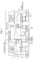
- FIG. 1 is a block diagram showing a configuration of a vehicle information control device indicating an embodiment of the present invention.
- Central processing units 1 and 1A included in leading vehicles, collect information of vehicles to execute processing of the entire formation.
- a terminal processing device 2 transmits input/output signals from vehicle apparatuses mounted on intermediate vehicles other than the leading vehicle as well as output information processed by the terminal processing device 2 to the central processing units 1 and 1A.
- Reference numerals 3A to 3F denote loads of the vehicle apparatuses, and reference numeral 4 denotes input information from the loads of the entire vehicles.
- the central processing units 1 and 1A receive the input information 4 from the loads of the entire vehicles through a core transmission 5 and executes input/output determination processes 6 and 6A of determining activation/termination within the power supply capacities of the vehicles based on the received information.
- Results determined in the input/output determination processes 6 and 6A by the central processing units 1 and 1A are handled as output information 7, and instructions are transmitted to the vehicle apparatuses through the core transmission 5.
- the vehicle apparatuses are activated based on the output information 7 by using power supplies from overhead wiring or external power supplies.
- FIG. 2 is an example of a flow chart describing an input/output determination process.
- a feeding state to the vehicle (for example, external feeding state from an external power supply outside of the vehicle) is determined in a process 21. If the state is the external feeding state (YES in process 21), the process branches to a process 22 to execute a priority activation control process in external feeding. In the following process 23, ON/OFF of the apparatuses mounted on the vehicle in external feeding is determined. In the following process 24, surplus power is calculated from the total electric energy usable in external feeding and the currently used electric energy. In the following process 36, the surplus power is distributed to the apparatuses with different loads between the cars, such as air conditioners, by taking abnormal states of the apparatuses into account. In a process 37, operation/termination instructions of the apparatuses are output.
- the process branches to a process 25 to determine whether the vehicle transmission is normal. If it is determined that the vehicle transmission is normal (YES in process 25), the process branches to a process 26 to determine whether a load reduction process due to a reduction in the number of operating auxiliary power supply devices in the entire formation is unnecessary. If the load reduction process is unnecessary (YES in process 26), priority activation control is performed in the following process 28, and ON/OFF of the apparatuses is determined in a process 29.
- the surplus power is calculated from the total electric energy usable by the vehicles and the currently used electric energy.
- the surplus power is distributed to the apparatuses with different loads between the cars, such as air conditioners, by taking abnormal states of the apparatuses into account.
- operation/termination instructions of the apparatuses are output.
- the process branches to a process 27 to execute a reduction process of limiting the loads of the apparatuses so as not to affect the operation of the vehicles.
- a process 27 to execute a reduction process of limiting the loads of the apparatuses so as not to affect the operation of the vehicles.
- the activation of equipment that does not affect the operation of the vehicles such as a water heater and a kitchen, is terminated in part of the cars.
- Apparatuses that affect the operation of the vehicles, such as compressors are limited by, for example, 50% according to the number of operating auxiliary power supply devices. In this way, load capacities of the apparatuses necessary for the operation of the vehicles are secured. After the load capacities of the apparatuses necessary for the operation of the vehicles are secured, the following processes 28 to 30, 36, and 37 are executed.
- FIG. 3 is an example of a flow chart describing an input/output determination process when the vehicle transmission is abnormal.
- a priority activation control process when the vehicle transmission is abnormal is executed in the following process 31, and whether a load reduction process due to a reduction in the number of operating auxiliary power supply devices in vehicles with normal vehicle transmission is unnecessary is determined in the following process 32. If the load reduction process is unnecessary (YES in process 32), the process branches to a process 34, and ON/OFF of the apparatuses when the vehicle transmission is abnormal is determined.
- maximum electric energy used by the vehicle with abnormal vehicle transmission is calculated based on the car with the transmission abnormality, and surplus power is calculated from the calculated maximum electric energy used by the vehicle with abnormal vehicle transmission, total electric energy usable by the vehicles with normal vehicle transmission, and the currently used electric energy.
- the surplus power is distributed to the apparatuses with different loads between the cars, such as air conditioners, by taking abnormal states of the apparatuses into account.
- operation/termination instructions of the apparatuses are output.
- the surplus power can be secured to distribute power to other apparatuses such as air conditioners, and the loads suitable for the operation of the vehicles can be activated and terminated.
- the central processing units of the leading vehicles can comprehensively and collectively execute a load management function of the vehicle apparatuses, and for example, a user (such as a driver and repair personnel) can immediately control the priority activation or the load limits from the driver's seat or the like.
- the vehicle information control device featured by a load management function of limiting the loads of the apparatuses to calculate and distribute the surplus power has been described.
- a load management function of limiting the loads of the apparatuses to calculate and distribute the surplus power.
- FIG. 4 is a display example of a screen indicating states of apparatuses for limiting the loads.
- a display screen 40 of a display device not shown has a screen format 41 including: a key area 42 for screen transition and the like; and a display area 43 for displaying, for each vehicle (car), operation states of the apparatuses for limiting the loads.
- the key area 42 for screen transition and the like is provided with a "load limit setting" key 44 for shifting the screen to a screen for setting the load limits.
- a "load limit setting” key 44 for shifting the screen to a screen for setting the load limits.
- FIG. 5 is a display example of the "load limit setting" screen for setting validation/invalidation of the load limits.
- a "limited” key and a “not limited” key shown in 51 are arranged for each apparatus for limiting the loads shown in 50.
- the key When the key is selected and input, the key enters a pressed state in a state that the validation/invalidation can be set, and the set information is reflected on the process 27 of FIG. 2 or the process 33 of FIG. 3 to perform the setting. If the minimum required electric energy of the apparatus in the operation of the vehicle cannot be secured by invalidating the load limit, a guidance indicating a cause (reason) that the load limit cannot be invalidated is displayed on a guidance display area 52, and the key operation is invalidated.
- the load limit instructions can be simply and collectively removed only by the screen operation of the display device, without inhibiting the operation of the vehicles.
- a "priority activation setting" key 45 for switching the screen to a screen for changing the order of the priority activation is arranged as shown in FIG. 4 .
- the screen is switched to a “priority activation setting” screen shown in FIG. 6 .
- FIG. 6 is a display example of the "priority activation setting" screen for setting the order of priority activation.
- Selection keys of the apparatuses for limiting the loads shown in 60 are arranged, and a priority display area 62 for displaying priorities that are set according to the apparatuses is arranged.
- a display area 61 is also arranged to display keys for changing the priorities (for example, numeric keys as shown in FIG. 6 ), a display area for displaying the priority selected by the keys for changing the priorities (above the arrangement of the numeric keys of FIG. 6 ), a setting key for setting the priority selected by the keys for changing the priorities, and a cancel key for cancelling the priority selected by the keys for changing the priorities.
- the setting key for setting the priority When the setting key for setting the priority is selected and input, the same value as in the display area for displaying the priority selected by the keys for changing the priorities is displayed on the priority display area 62.
- the set priority information is reflected on the processes 22 and 28 of FIG. 2 or on the process 31 of FIG. 3 in a state that the priority can be changed after a change key 63 is selected and input. In this way, the priority is changed.
- a guidance indicating a cause (reason) that the priority cannot be changed is displayed on a guidance display area 64 in FIG. 6 , and the change is invalidated.
- an initialization key 65 can be selected and input to restore the initial order of priority.
- a guidance indicating a cause (reason) that the priority cannot be changed is displayed on the guidance display area 64, and the initial order of priority can be restored after invalidating the change.
- the priority order of the priority activation control process can be simply and collectively changed only by the screen operation of the display device without inhibiting the operation of the vehicles.
- the present invention is not limited to the embodiments and includes various modified examples.
- the present invention may not include all of the components described above, and a component of an embodiment can be added to the components of another embodiment.
Landscapes
- Engineering & Computer Science (AREA)
- Power Engineering (AREA)
- Transportation (AREA)
- Mechanical Engineering (AREA)
- Life Sciences & Earth Sciences (AREA)
- Sustainable Development (AREA)
- Sustainable Energy (AREA)
- Electric Propulsion And Braking For Vehicles (AREA)
- Direct Current Feeding And Distribution (AREA)
- Train Traffic Observation, Control, And Security (AREA)
Abstract
Description
- The present invention relates to a vehicle information control device with a load management function.
- Configurations of apparatuses mounted on vehicles have changed in various ways with an advance in the computerization of the vehicles. It is difficult to provide each apparatus with a function related to the entire formation of the vehicles, such as determining operation of an apparatus while figuring out operation states of the other apparatuses. Therefore, a function of managing the entire vehicle formation by a vehicle information control device that can manage information of the entire vehicles and that can check the operation states of the apparatuses mounted on the vehicles is added in many cases.
- In general, a system of activating loads of a plurality of apparatuses mounted on a plurality of vehicles based on priorities so as to set the current supplied to the loads of the apparatuses within a rated range is performed as a load management function in a train with connected vehicles (Japanese Patent Laid-Open Publication No.
61-164477 - With a reduction in the capacity of the total power of the entire vehicles, a vehicle information control device performs a load management function of limiting loads of apparatuses according to states of the apparatuses mounted on the vehicles within a capacity range and calculating and distributing surplus power, the vehicle information control device comprising: a screen for displaying states of the apparatuses that allows easily determining the apparatuses for limiting the load capacities; a screen for changing load limits; and a screen for changing priorities, wherein from the screen for displaying the states of the apparatuses that allows easily determining the apparatuses for limiting the load capacities, the priorities and the load limits can be arbitrarily set by key operation corresponding to the screen for changing the load limits and corresponding to the screen for changing the priorities.
- The user can arbitrarily set the priorities and the load limits, and specifically, simple and collective setting by only the screen operation is possible. As a result, even if an apparatus with a low priority needs to be temporarily operated depending on the operation state of the vehicles, the apparatus can be operated while securing the minimum required electric energy in the operation of the vehicles.
-
-
FIG. 1 is a block diagram showing a configuration of a vehicle information control device; -
FIG. 2 shows input/output determination processing details (processing flow); -
FIG. 3 shows input/output determination processing details when vehicle transmission is abnormal (processing flow); -
FIG. 4 is a screen display example showing apparatus states for limiting loads; -
FIG. 5 is a screen display example of setting validation/invalidation of limits of the loads; and -
FIG. 6 is a screen display example of setting an order of priority activation. - Hereinafter, embodiments of the present invention will be described with reference to the drawings.
-
FIG. 1 is a block diagram showing a configuration of a vehicle information control device indicating an embodiment of the present invention. -
Central processing units terminal processing device 2 transmits input/output signals from vehicle apparatuses mounted on intermediate vehicles other than the leading vehicle as well as output information processed by theterminal processing device 2 to thecentral processing units Reference numerals 3A to 3F denote loads of the vehicle apparatuses, andreference numeral 4 denotes input information from the loads of the entire vehicles. Thecentral processing units input information 4 from the loads of the entire vehicles through acore transmission 5 and executes input/output determination processes output determination processes central processing units output information 7, and instructions are transmitted to the vehicle apparatuses through thecore transmission 5. The vehicle apparatuses are activated based on theoutput information 7 by using power supplies from overhead wiring or external power supplies. -
FIG. 2 is an example of a flow chart describing an input/output determination process. - When the vehicle power supply is turned on, a feeding state to the vehicle (for example, external feeding state from an external power supply outside of the vehicle) is determined in a
process 21. If the state is the external feeding state (YES in process 21), the process branches to aprocess 22 to execute a priority activation control process in external feeding. In the followingprocess 23, ON/OFF of the apparatuses mounted on the vehicle in external feeding is determined. In the followingprocess 24, surplus power is calculated from the total electric energy usable in external feeding and the currently used electric energy. In the followingprocess 36, the surplus power is distributed to the apparatuses with different loads between the cars, such as air conditioners, by taking abnormal states of the apparatuses into account. In aprocess 37, operation/termination instructions of the apparatuses are output. - On the other hand, if the state is not the external feeding state (NO in process 21), the process branches to a
process 25 to determine whether the vehicle transmission is normal. If it is determined that the vehicle transmission is normal (YES in process 25), the process branches to aprocess 26 to determine whether a load reduction process due to a reduction in the number of operating auxiliary power supply devices in the entire formation is unnecessary. If the load reduction process is unnecessary (YES in process 26), priority activation control is performed in the followingprocess 28, and ON/OFF of the apparatuses is determined in aprocess 29. In the followingprocess 30, the surplus power is calculated from the total electric energy usable by the vehicles and the currently used electric energy. In the followingprocess 36, the surplus power is distributed to the apparatuses with different loads between the cars, such as air conditioners, by taking abnormal states of the apparatuses into account. In theprocess 37, operation/termination instructions of the apparatuses are output. - If the load reduction process due to a reduction in the number of operating auxiliary power supply devices in the entire formation is necessary (NO in process 26), the process branches to a
process 27 to execute a reduction process of limiting the loads of the apparatuses so as not to affect the operation of the vehicles. For example, the activation of equipment that does not affect the operation of the vehicles, such as a water heater and a kitchen, is terminated in part of the cars. Apparatuses that affect the operation of the vehicles, such as compressors, are limited by, for example, 50% according to the number of operating auxiliary power supply devices. In this way, load capacities of the apparatuses necessary for the operation of the vehicles are secured. After the load capacities of the apparatuses necessary for the operation of the vehicles are secured, the followingprocesses 28 to 30, 36, and 37 are executed. - In this way, the management of both securing the load capacities of the apparatuses necessary for the operation of the vehicles and distributing the power to the other apparatuses, such as air conditioners, from the surplus power can be realized.
-
FIG. 3 is an example of a flow chart describing an input/output determination process when the vehicle transmission is abnormal. - If it is determined that the vehicle transmission is abnormal (NO in process 25), a priority activation control process when the vehicle transmission is abnormal is executed in the following
process 31, and whether a load reduction process due to a reduction in the number of operating auxiliary power supply devices in vehicles with normal vehicle transmission is unnecessary is determined in the followingprocess 32. If the load reduction process is unnecessary (YES in process 32), the process branches to aprocess 34, and ON/OFF of the apparatuses when the vehicle transmission is abnormal is determined. In the followingprocess 35, maximum electric energy used by the vehicle with abnormal vehicle transmission is calculated based on the car with the transmission abnormality, and surplus power is calculated from the calculated maximum electric energy used by the vehicle with abnormal vehicle transmission, total electric energy usable by the vehicles with normal vehicle transmission, and the currently used electric energy. In the followingprocess 36, the surplus power is distributed to the apparatuses with different loads between the cars, such as air conditioners, by taking abnormal states of the apparatuses into account. In theprocess 37, operation/termination instructions of the apparatuses are output. - If the load reduction process is necessary in the process 32 (NO in process 32), a reduction process of limiting the loads of the apparatuses is executed in the following
process 33 so as not to affect the operation of the vehicles. After the load capacities of the apparatuses necessary for the operation of the vehicles are secured, the followingprocesses 34 to 37 are executed. - In this way, even if the vehicle transmission is abnormal, the surplus power can be secured to distribute power to other apparatuses such as air conditioners, and the loads suitable for the operation of the vehicles can be activated and terminated.
- Therefore, the central processing units of the leading vehicles can comprehensively and collectively execute a load management function of the vehicle apparatuses, and for example, a user (such as a driver and repair personnel) can immediately control the priority activation or the load limits from the driver's seat or the like.
- In the first embodiment, the vehicle information control device featured by a load management function of limiting the loads of the apparatuses to calculate and distribute the surplus power has been described. In a second embodiment, an example of simply and collectively changing the load limits of the apparatuses by only screen operation of a display device will be specifically described.
-
FIG. 4 is a display example of a screen indicating states of apparatuses for limiting the loads. - A
display screen 40 of a display device not shown has ascreen format 41 including: akey area 42 for screen transition and the like; and adisplay area 43 for displaying, for each vehicle (car), operation states of the apparatuses for limiting the loads. - To change the load limits, the
key area 42 for screen transition and the like is provided with a "load limit setting"key 44 for shifting the screen to a screen for setting the load limits. When the "load limit setting"key 44 is selected and input, the screen shifts to a "load limit setting" screen shown inFIG. 5 . -
FIG. 5 is a display example of the "load limit setting" screen for setting validation/invalidation of the load limits. - A "limited" key and a "not limited" key shown in 51 are arranged for each apparatus for limiting the loads shown in 50. When the key is selected and input, the key enters a pressed state in a state that the validation/invalidation can be set, and the set information is reflected on the
process 27 ofFIG. 2 or theprocess 33 ofFIG. 3 to perform the setting. If the minimum required electric energy of the apparatus in the operation of the vehicle cannot be secured by invalidating the load limit, a guidance indicating a cause (reason) that the load limit cannot be invalidated is displayed on aguidance display area 52, and the key operation is invalidated. - As a result, when load does not have to be limited, the load limit instructions can be simply and collectively removed only by the screen operation of the display device, without inhibiting the operation of the vehicles.
- When the order of priority activation is changed as necessary, a "priority activation setting"
key 45 for switching the screen to a screen for changing the order of the priority activation is arranged as shown inFIG. 4 . When the "priority activation setting"key 45 is selected and input, the screen is switched to a "priority activation setting" screen shown inFIG. 6 . -
FIG. 6 is a display example of the "priority activation setting" screen for setting the order of priority activation. - Selection keys of the apparatuses for limiting the loads shown in 60 are arranged, and a
priority display area 62 for displaying priorities that are set according to the apparatuses is arranged. Adisplay area 61 is also arranged to display keys for changing the priorities (for example, numeric keys as shown inFIG. 6 ), a display area for displaying the priority selected by the keys for changing the priorities (above the arrangement of the numeric keys ofFIG. 6 ), a setting key for setting the priority selected by the keys for changing the priorities, and a cancel key for cancelling the priority selected by the keys for changing the priorities. - When the setting key for setting the priority is selected and input, the same value as in the display area for displaying the priority selected by the keys for changing the priorities is displayed on the
priority display area 62. To carry out the order activation by the priority in thepriority display area 62, the set priority information is reflected on theprocesses FIG. 2 or on theprocess 31 ofFIG. 3 in a state that the priority can be changed after achange key 63 is selected and input. In this way, the priority is changed. - When the minimum required electric energy of the apparatuses in the operation of the vehicles cannot be secured by changing the priority, a guidance indicating a cause (reason) that the priority cannot be changed is displayed on a
guidance display area 64 inFIG. 6 , and the change is invalidated. To restore the priority as necessary, aninitialization key 65 can be selected and input to restore the initial order of priority. - When the minimum required electric energy of the apparatuses in the operation of the vehicles cannot be secured due to a failure or the like of an apparatus after the priority is changed, a guidance indicating a cause (reason) that the priority cannot be changed is displayed on the
guidance display area 64, and the initial order of priority can be restored after invalidating the change. - As a result, when the priority order of the priority activation control process is changed, the priority order can be simply and collectively changed only by the screen operation of the display device without inhibiting the operation of the vehicles.
- The present invention is not limited to the embodiments and includes various modified examples. The present invention may not include all of the components described above, and a component of an embodiment can be added to the components of another embodiment.
Claims (5)
- A vehicle information control device with a load management function, wherein to set power within capacity ranges of vehicle power supplies mounted on a plurality of vehicles, states of the vehicle power supplies and vehicle transmission are detected, priority activation of vehicle apparatuses is controlled, loads of the vehicle apparatuses are limited by load limit instructions of the vehicle apparatuses generated according to the detected states, and then surplus power is calculated and distributed.
- The vehicle information control device according to claim 1, wherein
the states of the vehicle power supplies are feeding states to the vehicles and states of auxiliary power supply devices of the vehicles. - The vehicle information control device according to claim 1 or 2, wherein
a priority activation order of the vehicle apparatuses is set and changed by screen operation of a display device. - The vehicle information control device according to claim 1 or 2, wherein
validation or invalidation of the load limit instructions is individually set and changed for the vehicle apparatuses by screen operation of the display device. - The vehicle information control device according to claim 3 or 4, wherein
in a case that the setting change by the screen operation of the display device cannot be performed, a guidance indicating a cause is displayed to invalidate the setting change.
Applications Claiming Priority (1)
| Application Number | Priority Date | Filing Date | Title |
|---|---|---|---|
| JP2012187572A JP5753138B2 (en) | 2012-08-28 | 2012-08-28 | Vehicle information control device with load management function |
Publications (3)
| Publication Number | Publication Date |
|---|---|
| EP2704290A2 true EP2704290A2 (en) | 2014-03-05 |
| EP2704290A3 EP2704290A3 (en) | 2017-02-08 |
| EP2704290B1 EP2704290B1 (en) | 2022-09-28 |
Family
ID=49033847
Family Applications (1)
| Application Number | Title | Priority Date | Filing Date |
|---|---|---|---|
| EP13181078.0A Active EP2704290B1 (en) | 2012-08-28 | 2013-08-20 | Vehicle information control device with load management function |
Country Status (4)
| Country | Link |
|---|---|
| EP (1) | EP2704290B1 (en) |
| JP (1) | JP5753138B2 (en) |
| KR (1) | KR101538847B1 (en) |
| CN (1) | CN103677060B (en) |
Cited By (1)
| Publication number | Priority date | Publication date | Assignee | Title |
|---|---|---|---|---|
| CN113511099A (en) * | 2021-04-29 | 2021-10-19 | 江苏爱玛车业科技有限公司 | Charging method, device and system of electric vehicle |
Families Citing this family (6)
| Publication number | Priority date | Publication date | Assignee | Title |
|---|---|---|---|---|
| CN108248388A (en) * | 2016-12-28 | 2018-07-06 | 中车株洲电力机车研究所有限公司 | The low-voltage distribution system of intelligent self- steering rubber tire low-floor truck combination |
| CN112572161B (en) * | 2019-09-29 | 2022-04-15 | 比亚迪股份有限公司 | Vehicle driving control method and device and vehicle |
| JP2021189491A (en) * | 2020-05-25 | 2021-12-13 | トヨタ自動車株式会社 | Information processing device and method |
| KR102878559B1 (en) * | 2020-09-08 | 2025-10-30 | 삼성전자주식회사 | Air conditioning system, air conditioning control appratus and cotnrol method of the same |
| JP7464069B2 (en) * | 2022-03-14 | 2024-04-09 | いすゞ自動車株式会社 | Power supply control device |
| JP7740282B2 (en) * | 2023-02-10 | 2025-09-17 | 株式会社デンソー | Switch-off device and program |
Citations (1)
| Publication number | Priority date | Publication date | Assignee | Title |
|---|---|---|---|---|
| JPS61164477A (en) | 1985-01-12 | 1986-07-25 | Mitsubishi Electric Corp | Sequentially starting method of loads |
Family Cites Families (11)
| Publication number | Priority date | Publication date | Assignee | Title |
|---|---|---|---|---|
| JPH0530765A (en) * | 1991-06-25 | 1993-02-05 | Toshiba Corp | Electric motor sequence start / stop device |
| JPH06178402A (en) * | 1992-12-09 | 1994-06-24 | Toshiba Corp | Controlling equipment for air-conditioning operation in railway vehicle |
| JP3274043B2 (en) * | 1995-07-31 | 2002-04-15 | 三菱電機株式会社 | Vehicle monitoring device |
| JPH09130901A (en) * | 1995-10-31 | 1997-05-16 | Hitachi Ltd | Control device for on-board electrical equipment |
| JP3906801B2 (en) * | 2002-12-27 | 2007-04-18 | 松下電工株式会社 | Apartment house home automation system |
| JP4087283B2 (en) * | 2003-04-25 | 2008-05-21 | 京セラミタ株式会社 | Equipment with power saving mode function |
| EP1777116A1 (en) * | 2005-10-19 | 2007-04-25 | C.R.F. Società Consortile per Azioni | A system for managing the supply of electrical energy in a motor vehicle |
| CA2658684C (en) * | 2006-08-10 | 2014-04-29 | Mitsubishi Electric Corporation | Control apparatus for electric vehicle |
| CN100574000C (en) * | 2007-08-31 | 2009-12-23 | 奇瑞汽车股份有限公司 | Automotive Power Management System |
| JP2011004566A (en) * | 2009-06-22 | 2011-01-06 | Toshiba Corp | Auxiliary power supply apparatus for electric vehicle |
| KR101661147B1 (en) * | 2010-11-12 | 2016-09-29 | 엘지전자 주식회사 | Battery controlling apparatus for electrical vehicle and method thereof |
-
2012
- 2012-08-28 JP JP2012187572A patent/JP5753138B2/en active Active
-
2013
- 2013-08-01 CN CN201310331460.8A patent/CN103677060B/en active Active
- 2013-08-08 KR KR1020130094118A patent/KR101538847B1/en not_active Expired - Fee Related
- 2013-08-20 EP EP13181078.0A patent/EP2704290B1/en active Active
Patent Citations (1)
| Publication number | Priority date | Publication date | Assignee | Title |
|---|---|---|---|---|
| JPS61164477A (en) | 1985-01-12 | 1986-07-25 | Mitsubishi Electric Corp | Sequentially starting method of loads |
Cited By (1)
| Publication number | Priority date | Publication date | Assignee | Title |
|---|---|---|---|---|
| CN113511099A (en) * | 2021-04-29 | 2021-10-19 | 江苏爱玛车业科技有限公司 | Charging method, device and system of electric vehicle |
Also Published As
| Publication number | Publication date |
|---|---|
| JP2014045613A (en) | 2014-03-13 |
| KR20140029180A (en) | 2014-03-10 |
| CN103677060B (en) | 2015-10-28 |
| KR101538847B1 (en) | 2015-07-22 |
| EP2704290B1 (en) | 2022-09-28 |
| CN103677060A (en) | 2014-03-26 |
| EP2704290A3 (en) | 2017-02-08 |
| JP5753138B2 (en) | 2015-07-22 |
Similar Documents
| Publication | Publication Date | Title |
|---|---|---|
| EP2704290B1 (en) | Vehicle information control device with load management function | |
| US6633802B2 (en) | Power management under limited power conditions | |
| CN107074173B (en) | Vehicle power box device | |
| EP2394417B1 (en) | Aircraft hybrid cockpit control panel system | |
| US10272795B2 (en) | Electronic control device for controlling a vehicle battery pack and system employing such a device | |
| JPH1141807A (en) | Energy distribution equipment | |
| DE112013007450T5 (en) | Accumulator type vehicle, cargo management system and cargo management method | |
| EP3439130A1 (en) | Power management apparatus, power management system, and power management method | |
| CN105340150A (en) | Charging state management method, charging state management device, and program | |
| CN106444454B (en) | Energy control method and control device for power utilization system | |
| EP3370291A1 (en) | Fuel cell device, fuel cell system, method for controlling fuel cell system, and controller | |
| JP2013025570A (en) | Electronic control unit | |
| CN105172715A (en) | Multifunctional low-voltage distribution box for electric vehicle | |
| US9533637B2 (en) | Smart power outlet system | |
| JP2010183775A (en) | Building management system | |
| US20150063165A1 (en) | Data sharing system between master inverter and slave inverter | |
| KR20200061200A (en) | Operation apparatus for substation and the control method thereof | |
| EP3287310B1 (en) | Train data transmission system and train data transmission program | |
| US20120306276A1 (en) | Electrical and/or electronic supply circuit and method for providing a supply voltage | |
| CN115157959A (en) | Integrated control system for refrigerator car and refrigerator car | |
| US20160334769A1 (en) | Modular generator control and external power unit | |
| JP2015099621A (en) | Integrated controller, and integrated management system | |
| JP2010041804A (en) | Power supply system controller for vehicle | |
| EP3895994B1 (en) | Adaptive aircraft electrical power distribution system | |
| CN211426671U (en) | Testing device |
Legal Events
| Date | Code | Title | Description |
|---|---|---|---|
| 17P | Request for examination filed |
Effective date: 20130906 |
|
| AK | Designated contracting states |
Kind code of ref document: A2 Designated state(s): AL AT BE BG CH CY CZ DE DK EE ES FI FR GB GR HR HU IE IS IT LI LT LU LV MC MK MT NL NO PL PT RO RS SE SI SK SM TR |
|
| AX | Request for extension of the european patent |
Extension state: BA ME |
|
| PUAI | Public reference made under article 153(3) epc to a published international application that has entered the european phase |
Free format text: ORIGINAL CODE: 0009012 |
|
| PUAL | Search report despatched |
Free format text: ORIGINAL CODE: 0009013 |
|
| AK | Designated contracting states |
Kind code of ref document: A3 Designated state(s): AL AT BE BG CH CY CZ DE DK EE ES FI FR GB GR HR HU IE IS IT LI LT LU LV MC MK MT NL NO PL PT RO RS SE SI SK SM TR |
|
| AX | Request for extension of the european patent |
Extension state: BA ME |
|
| RIC1 | Information provided on ipc code assigned before grant |
Ipc: B60L 1/00 20060101ALI20170103BHEP Ipc: H02J 7/00 20060101AFI20170103BHEP Ipc: H02J 4/00 20060101ALN20170103BHEP Ipc: H04N 1/00 20060101ALN20170103BHEP |
|
| STAA | Information on the status of an ep patent application or granted ep patent |
Free format text: STATUS: EXAMINATION IS IN PROGRESS |
|
| 17Q | First examination report despatched |
Effective date: 20200324 |
|
| GRAP | Despatch of communication of intention to grant a patent |
Free format text: ORIGINAL CODE: EPIDOSNIGR1 |
|
| STAA | Information on the status of an ep patent application or granted ep patent |
Free format text: STATUS: GRANT OF PATENT IS INTENDED |
|
| INTG | Intention to grant announced |
Effective date: 20220224 |
|
| GRAS | Grant fee paid |
Free format text: ORIGINAL CODE: EPIDOSNIGR3 |
|
| RAP1 | Party data changed (applicant data changed or rights of an application transferred) |
Owner name: HITACHI BUILDING SYSTEMS CO., LTD. Owner name: HITACHI, LTD. |
|
| GRAA | (expected) grant |
Free format text: ORIGINAL CODE: 0009210 |
|
| STAA | Information on the status of an ep patent application or granted ep patent |
Free format text: STATUS: THE PATENT HAS BEEN GRANTED |
|
| AK | Designated contracting states |
Kind code of ref document: B1 Designated state(s): AL AT BE BG CH CY CZ DE DK EE ES FI FR GB GR HR HU IE IS IT LI LT LU LV MC MK MT NL NO PL PT RO RS SE SI SK SM TR |
|
| REG | Reference to a national code |
Ref country code: GB Ref legal event code: FG4D |
|
| REG | Reference to a national code |
Ref country code: CH Ref legal event code: EP |
|
| REG | Reference to a national code |
Ref country code: AT Ref legal event code: REF Ref document number: 1521887 Country of ref document: AT Kind code of ref document: T Effective date: 20221015 |
|
| REG | Reference to a national code |
Ref country code: DE Ref legal event code: R096 Ref document number: 602013082579 Country of ref document: DE |
|
| REG | Reference to a national code |
Ref country code: IE Ref legal event code: FG4D |
|
| REG | Reference to a national code |
Ref country code: LT Ref legal event code: MG9D |
|
| PG25 | Lapsed in a contracting state [announced via postgrant information from national office to epo] |
Ref country code: SE Free format text: LAPSE BECAUSE OF FAILURE TO SUBMIT A TRANSLATION OF THE DESCRIPTION OR TO PAY THE FEE WITHIN THE PRESCRIBED TIME-LIMIT Effective date: 20220928 Ref country code: RS Free format text: LAPSE BECAUSE OF FAILURE TO SUBMIT A TRANSLATION OF THE DESCRIPTION OR TO PAY THE FEE WITHIN THE PRESCRIBED TIME-LIMIT Effective date: 20220928 Ref country code: NO Free format text: LAPSE BECAUSE OF FAILURE TO SUBMIT A TRANSLATION OF THE DESCRIPTION OR TO PAY THE FEE WITHIN THE PRESCRIBED TIME-LIMIT Effective date: 20221228 Ref country code: LV Free format text: LAPSE BECAUSE OF FAILURE TO SUBMIT A TRANSLATION OF THE DESCRIPTION OR TO PAY THE FEE WITHIN THE PRESCRIBED TIME-LIMIT Effective date: 20220928 Ref country code: LT Free format text: LAPSE BECAUSE OF FAILURE TO SUBMIT A TRANSLATION OF THE DESCRIPTION OR TO PAY THE FEE WITHIN THE PRESCRIBED TIME-LIMIT Effective date: 20220928 Ref country code: FI Free format text: LAPSE BECAUSE OF FAILURE TO SUBMIT A TRANSLATION OF THE DESCRIPTION OR TO PAY THE FEE WITHIN THE PRESCRIBED TIME-LIMIT Effective date: 20220928 |
|
| REG | Reference to a national code |
Ref country code: NL Ref legal event code: MP Effective date: 20220928 |
|
| REG | Reference to a national code |
Ref country code: AT Ref legal event code: MK05 Ref document number: 1521887 Country of ref document: AT Kind code of ref document: T Effective date: 20220928 |
|
| PG25 | Lapsed in a contracting state [announced via postgrant information from national office to epo] |
Ref country code: HR Free format text: LAPSE BECAUSE OF FAILURE TO SUBMIT A TRANSLATION OF THE DESCRIPTION OR TO PAY THE FEE WITHIN THE PRESCRIBED TIME-LIMIT Effective date: 20220928 Ref country code: GR Free format text: LAPSE BECAUSE OF FAILURE TO SUBMIT A TRANSLATION OF THE DESCRIPTION OR TO PAY THE FEE WITHIN THE PRESCRIBED TIME-LIMIT Effective date: 20221229 |
|
| PG25 | Lapsed in a contracting state [announced via postgrant information from national office to epo] |
Ref country code: SM Free format text: LAPSE BECAUSE OF FAILURE TO SUBMIT A TRANSLATION OF THE DESCRIPTION OR TO PAY THE FEE WITHIN THE PRESCRIBED TIME-LIMIT Effective date: 20220928 Ref country code: RO Free format text: LAPSE BECAUSE OF FAILURE TO SUBMIT A TRANSLATION OF THE DESCRIPTION OR TO PAY THE FEE WITHIN THE PRESCRIBED TIME-LIMIT Effective date: 20220928 Ref country code: PT Free format text: LAPSE BECAUSE OF FAILURE TO SUBMIT A TRANSLATION OF THE DESCRIPTION OR TO PAY THE FEE WITHIN THE PRESCRIBED TIME-LIMIT Effective date: 20230130 Ref country code: ES Free format text: LAPSE BECAUSE OF FAILURE TO SUBMIT A TRANSLATION OF THE DESCRIPTION OR TO PAY THE FEE WITHIN THE PRESCRIBED TIME-LIMIT Effective date: 20220928 Ref country code: CZ Free format text: LAPSE BECAUSE OF FAILURE TO SUBMIT A TRANSLATION OF THE DESCRIPTION OR TO PAY THE FEE WITHIN THE PRESCRIBED TIME-LIMIT Effective date: 20220928 Ref country code: AT Free format text: LAPSE BECAUSE OF FAILURE TO SUBMIT A TRANSLATION OF THE DESCRIPTION OR TO PAY THE FEE WITHIN THE PRESCRIBED TIME-LIMIT Effective date: 20220928 |
|
| PG25 | Lapsed in a contracting state [announced via postgrant information from national office to epo] |
Ref country code: SK Free format text: LAPSE BECAUSE OF FAILURE TO SUBMIT A TRANSLATION OF THE DESCRIPTION OR TO PAY THE FEE WITHIN THE PRESCRIBED TIME-LIMIT Effective date: 20220928 Ref country code: PL Free format text: LAPSE BECAUSE OF FAILURE TO SUBMIT A TRANSLATION OF THE DESCRIPTION OR TO PAY THE FEE WITHIN THE PRESCRIBED TIME-LIMIT Effective date: 20220928 Ref country code: IS Free format text: LAPSE BECAUSE OF FAILURE TO SUBMIT A TRANSLATION OF THE DESCRIPTION OR TO PAY THE FEE WITHIN THE PRESCRIBED TIME-LIMIT Effective date: 20230128 Ref country code: EE Free format text: LAPSE BECAUSE OF FAILURE TO SUBMIT A TRANSLATION OF THE DESCRIPTION OR TO PAY THE FEE WITHIN THE PRESCRIBED TIME-LIMIT Effective date: 20220928 |
|
| REG | Reference to a national code |
Ref country code: DE Ref legal event code: R097 Ref document number: 602013082579 Country of ref document: DE |
|
| PG25 | Lapsed in a contracting state [announced via postgrant information from national office to epo] |
Ref country code: NL Free format text: LAPSE BECAUSE OF FAILURE TO SUBMIT A TRANSLATION OF THE DESCRIPTION OR TO PAY THE FEE WITHIN THE PRESCRIBED TIME-LIMIT Effective date: 20220928 Ref country code: AL Free format text: LAPSE BECAUSE OF FAILURE TO SUBMIT A TRANSLATION OF THE DESCRIPTION OR TO PAY THE FEE WITHIN THE PRESCRIBED TIME-LIMIT Effective date: 20220928 |
|
| PG25 | Lapsed in a contracting state [announced via postgrant information from national office to epo] |
Ref country code: DK Free format text: LAPSE BECAUSE OF FAILURE TO SUBMIT A TRANSLATION OF THE DESCRIPTION OR TO PAY THE FEE WITHIN THE PRESCRIBED TIME-LIMIT Effective date: 20220928 |
|
| PLBE | No opposition filed within time limit |
Free format text: ORIGINAL CODE: 0009261 |
|
| STAA | Information on the status of an ep patent application or granted ep patent |
Free format text: STATUS: NO OPPOSITION FILED WITHIN TIME LIMIT |
|
| 26N | No opposition filed |
Effective date: 20230629 |
|
| PGFP | Annual fee paid to national office [announced via postgrant information from national office to epo] |
Ref country code: IT Payment date: 20230711 Year of fee payment: 11 |
|
| PG25 | Lapsed in a contracting state [announced via postgrant information from national office to epo] |
Ref country code: SI Free format text: LAPSE BECAUSE OF FAILURE TO SUBMIT A TRANSLATION OF THE DESCRIPTION OR TO PAY THE FEE WITHIN THE PRESCRIBED TIME-LIMIT Effective date: 20220928 |
|
| PGFP | Annual fee paid to national office [announced via postgrant information from national office to epo] |
Ref country code: FR Payment date: 20230703 Year of fee payment: 11 Ref country code: DE Payment date: 20230627 Year of fee payment: 11 |
|
| PG25 | Lapsed in a contracting state [announced via postgrant information from national office to epo] |
Ref country code: MC Free format text: LAPSE BECAUSE OF FAILURE TO SUBMIT A TRANSLATION OF THE DESCRIPTION OR TO PAY THE FEE WITHIN THE PRESCRIBED TIME-LIMIT Effective date: 20220928 |
|
| REG | Reference to a national code |
Ref country code: CH Ref legal event code: PL |
|
| PG25 | Lapsed in a contracting state [announced via postgrant information from national office to epo] |
Ref country code: MC Free format text: LAPSE BECAUSE OF FAILURE TO SUBMIT A TRANSLATION OF THE DESCRIPTION OR TO PAY THE FEE WITHIN THE PRESCRIBED TIME-LIMIT Effective date: 20220928 |
|
| PG25 | Lapsed in a contracting state [announced via postgrant information from national office to epo] |
Ref country code: LU Free format text: LAPSE BECAUSE OF NON-PAYMENT OF DUE FEES Effective date: 20230820 |
|
| PG25 | Lapsed in a contracting state [announced via postgrant information from national office to epo] |
Ref country code: LU Free format text: LAPSE BECAUSE OF NON-PAYMENT OF DUE FEES Effective date: 20230820 Ref country code: CH Free format text: LAPSE BECAUSE OF NON-PAYMENT OF DUE FEES Effective date: 20230831 |
|
| REG | Reference to a national code |
Ref country code: BE Ref legal event code: MM Effective date: 20230831 |
|
| REG | Reference to a national code |
Ref country code: IE Ref legal event code: MM4A |
|
| PG25 | Lapsed in a contracting state [announced via postgrant information from national office to epo] |
Ref country code: IE Free format text: LAPSE BECAUSE OF NON-PAYMENT OF DUE FEES Effective date: 20230820 |
|
| PG25 | Lapsed in a contracting state [announced via postgrant information from national office to epo] |
Ref country code: IE Free format text: LAPSE BECAUSE OF NON-PAYMENT OF DUE FEES Effective date: 20230820 |
|
| PG25 | Lapsed in a contracting state [announced via postgrant information from national office to epo] |
Ref country code: BE Free format text: LAPSE BECAUSE OF NON-PAYMENT OF DUE FEES Effective date: 20230831 |
|
| PG25 | Lapsed in a contracting state [announced via postgrant information from national office to epo] |
Ref country code: BG Free format text: LAPSE BECAUSE OF FAILURE TO SUBMIT A TRANSLATION OF THE DESCRIPTION OR TO PAY THE FEE WITHIN THE PRESCRIBED TIME-LIMIT Effective date: 20220928 |
|
| PG25 | Lapsed in a contracting state [announced via postgrant information from national office to epo] |
Ref country code: BG Free format text: LAPSE BECAUSE OF FAILURE TO SUBMIT A TRANSLATION OF THE DESCRIPTION OR TO PAY THE FEE WITHIN THE PRESCRIBED TIME-LIMIT Effective date: 20220928 |
|
| REG | Reference to a national code |
Ref country code: DE Ref legal event code: R119 Ref document number: 602013082579 Country of ref document: DE |
|
| PG25 | Lapsed in a contracting state [announced via postgrant information from national office to epo] |
Ref country code: DE Free format text: LAPSE BECAUSE OF NON-PAYMENT OF DUE FEES Effective date: 20250301 |
|
| PG25 | Lapsed in a contracting state [announced via postgrant information from national office to epo] |
Ref country code: IT Free format text: LAPSE BECAUSE OF NON-PAYMENT OF DUE FEES Effective date: 20240820 |
|
| PG25 | Lapsed in a contracting state [announced via postgrant information from national office to epo] |
Ref country code: FR Free format text: LAPSE BECAUSE OF NON-PAYMENT OF DUE FEES Effective date: 20240831 |
|
| PG25 | Lapsed in a contracting state [announced via postgrant information from national office to epo] |
Ref country code: CY Free format text: LAPSE BECAUSE OF FAILURE TO SUBMIT A TRANSLATION OF THE DESCRIPTION OR TO PAY THE FEE WITHIN THE PRESCRIBED TIME-LIMIT; INVALID AB INITIO Effective date: 20130820 |
|
| PG25 | Lapsed in a contracting state [announced via postgrant information from national office to epo] |
Ref country code: HU Free format text: LAPSE BECAUSE OF FAILURE TO SUBMIT A TRANSLATION OF THE DESCRIPTION OR TO PAY THE FEE WITHIN THE PRESCRIBED TIME-LIMIT; INVALID AB INITIO Effective date: 20130820 |
|
| PGFP | Annual fee paid to national office [announced via postgrant information from national office to epo] |
Ref country code: GB Payment date: 20250703 Year of fee payment: 13 |
|
| PG25 | Lapsed in a contracting state [announced via postgrant information from national office to epo] |
Ref country code: TR Free format text: LAPSE BECAUSE OF FAILURE TO SUBMIT A TRANSLATION OF THE DESCRIPTION OR TO PAY THE FEE WITHIN THE PRESCRIBED TIME-LIMIT Effective date: 20220928 |