EP2703807B1 - Ultrasonic array transducer holder and guide for flanges having cutouts and asymmetric geometry - Google Patents
Ultrasonic array transducer holder and guide for flanges having cutouts and asymmetric geometry Download PDFInfo
- Publication number
- EP2703807B1 EP2703807B1 EP13182108.4A EP13182108A EP2703807B1 EP 2703807 B1 EP2703807 B1 EP 2703807B1 EP 13182108 A EP13182108 A EP 13182108A EP 2703807 B1 EP2703807 B1 EP 2703807B1
- Authority
- EP
- European Patent Office
- Prior art keywords
- holder
- web
- chord
- positioner
- base
- Prior art date
- Legal status (The legal status is an assumption and is not a legal conclusion. Google has not performed a legal analysis and makes no representation as to the accuracy of the status listed.)
- Active
Links
Images



Classifications
-
- G—PHYSICS
- G01—MEASURING; TESTING
- G01N—INVESTIGATING OR ANALYSING MATERIALS BY DETERMINING THEIR CHEMICAL OR PHYSICAL PROPERTIES
- G01N29/00—Investigating or analysing materials by the use of ultrasonic, sonic or infrasonic waves; Visualisation of the interior of objects by transmitting ultrasonic or sonic waves through the object
- G01N29/04—Analysing solids
- G01N29/06—Visualisation of the interior, e.g. acoustic microscopy
- G01N29/0609—Display arrangements, e.g. colour displays
- G01N29/0645—Display representation or displayed parameters, e.g. A-, B- or C-Scan
-
- G—PHYSICS
- G01—MEASURING; TESTING
- G01N—INVESTIGATING OR ANALYSING MATERIALS BY DETERMINING THEIR CHEMICAL OR PHYSICAL PROPERTIES
- G01N29/00—Investigating or analysing materials by the use of ultrasonic, sonic or infrasonic waves; Visualisation of the interior of objects by transmitting ultrasonic or sonic waves through the object
- G01N29/22—Details, e.g. general constructional or apparatus details
- G01N29/225—Supports, positioning or alignment in moving situation
-
- G—PHYSICS
- G01—MEASURING; TESTING
- G01N—INVESTIGATING OR ANALYSING MATERIALS BY DETERMINING THEIR CHEMICAL OR PHYSICAL PROPERTIES
- G01N29/00—Investigating or analysing materials by the use of ultrasonic, sonic or infrasonic waves; Visualisation of the interior of objects by transmitting ultrasonic or sonic waves through the object
- G01N29/22—Details, e.g. general constructional or apparatus details
- G01N29/26—Arrangements for orientation or scanning by relative movement of the head and the sensor
- G01N29/265—Arrangements for orientation or scanning by relative movement of the head and the sensor by moving the sensor relative to a stationary material
-
- G—PHYSICS
- G01—MEASURING; TESTING
- G01N—INVESTIGATING OR ANALYSING MATERIALS BY DETERMINING THEIR CHEMICAL OR PHYSICAL PROPERTIES
- G01N2291/00—Indexing codes associated with group G01N29/00
- G01N2291/02—Indexing codes associated with the analysed material
- G01N2291/023—Solids
- G01N2291/0231—Composite or layered materials
-
- G—PHYSICS
- G01—MEASURING; TESTING
- G01N—INVESTIGATING OR ANALYSING MATERIALS BY DETERMINING THEIR CHEMICAL OR PHYSICAL PROPERTIES
- G01N2291/00—Indexing codes associated with group G01N29/00
- G01N2291/10—Number of transducers
- G01N2291/106—Number of transducers one or more transducer arrays
-
- G—PHYSICS
- G01—MEASURING; TESTING
- G01N—INVESTIGATING OR ANALYSING MATERIALS BY DETERMINING THEIR CHEMICAL OR PHYSICAL PROPERTIES
- G01N2291/00—Indexing codes associated with group G01N29/00
- G01N2291/26—Scanned objects
- G01N2291/263—Surfaces
- G01N2291/2638—Complex surfaces
Definitions
- Embodiments of the disclosure relate generally to the field of ultrasonic testing systems and more particularly to a manipulable holder for an ultrasonic array to accommodate scanning with the array on composite elements such as T-chords having flanges with cutouts and asymmetric geometry.
- Ultrasonic scanning of composite parts is a key quality control capability. Imaging of surfaces is best conducted with scans along the surface in a substantially linear fashion. Where the ultrasonic array is not as wide as the surface to be scanned, multiple passes along the surface are required. Recording of accurate position information of the array during the scan is critical to obtain desired data coverage. The complexity of many composite parts makes alignment of the array in multiple scans challenging. With parts such as T-chords, the cap flange is likely to be asymmetric and typically has cutouts to accommodate mating components or required pass-throughs. Previous solutions have used the edge of the part being scanned to position the transducer with wide bases that span the largest cut out on the part.
- US 2011/0178727 A1 in accordance with its abstract states an "Apparatus for nondestructive inspection of structural elements or workpieces, in particular those having an airfoil configuration, that moves a scanning sensor across the width (span) of a structural element or workpiece for the purpose of detecting structural damage.
- the apparatus simultaneously traverses the length (chord) of the structural element or workpiece.
- the apparatus includes a guide rail that encompasses the structural element or workpiece and the scanning sensor travels along the guide rail from a first location at an upper rear region, to the front, of the structural element or workpiece, and then around the leading edge toward the lower rear region.
- the apparatus includes a processor and a display device to display the processed, sensed, information.”
- JP H05 209869 A in accordance with its abstract as translated states a "Purpose: To improve operation efficiency and also improve processing ability to save power by reducing time required for disassembly, assembly and preparation for installation.”; and a constitution wherein "Opposite plate ends of a thick steel plate are used as rails or rails are provided on the plate ends wherein a pair of guide wheels are brought into rotating contact with the rails.
- a lateral beam coupled to the guide wheels driven in a running direction by a running driving part and also a flaw detecting head is driven in a lateral direction by a lateral driving part on the lateral beam.
- Flaw detection of the thick steel plate can be done on its entire surface or with predetermined pitch intervals sampled by controlling the driving of the running driving part and the lateral driving part. Since the plate edges are used as the rails or the rails if provided may be of a simple structure, installation of a flaw detector is easy.”
- an ultrasonic inspection device for inspection of a T-chord, wherein the T-chord is a composite part and comprises a web, and a cap on the web, the cap having two flanges, the ultrasonic inspection device as defined in claim 1.
- a method for ultrasonic inspection of a T-chord wherein the T-chord is a composite part and comprises a web, and a cap having two flanges, the method as defined in claim 5.
- Embodiments disclosed herein provide a transducer incorporating an ultrasonic array and a positioner/holder having a base with a rail extending from the base to support the transducer in at least two lateral positions.
- a guide extends from the base for contact with a web of a composite shape. The guide maintains the rail substantially perpendicular to the web.
- An encoder is supported by the base and contacts a flange of the composite shape.
- the positioner/holder is adapted for longitudinal motion along the composite shape to create C-scans with the transducer without being impacted by asymmetric or irregular flange shapes or cutouts.
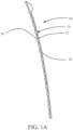
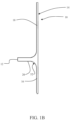
- T-chord 10 shown in FIGs. 1A and 1B .
- the T-chord has a web 12 and a cap 14 having an inner flange 16 and outer flange 18.
- a datum in the design of T-chords is a surface 20 of the web 12.
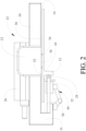
- FIGs. 2 through 7 An example embodiment of a transducer positioner/holder 22 as shown in FIGs. 2 through 7 employs a support rail 24 for a transducer 26 housing an ultrasonic array, such as a 3.5L128-NW3 linear transducer from Olympus 48 Woerd Ave, Waltham, MA 02453, to obtain C-scan data.
- a guide 28 which rides on the surface 20 of the web 12 is used to position a near edge 30 of a base 31 of the transducer positioner/holder 22 a set distance laterally from the web.
- the positioner/holder 22 holds the tranducer 26 normal to the web as the transducer positioner/holder is scanned longitudinally along the part.
- the guide 28 extends from the near edge 30 mounted on positioning rods 32 extending from the base 31.
- the guide 28 is dimensioned longitudinally (along the web) with sufficient length to provide stable perpendicularity of the support rail 24 relative to the web during the longitudinal scan. Wheels 29 or similar bearing elements extending from the guide 28 (best seen in FIG. 6 ) provide low friction engagement on surface 20 of the web 12. Positioning the transducer 26 to be normal to the scan direction avoids positional errors in the ultrasonic data that may lead to indications being hidden or incorrectly sized in the C-scan presentation.
- the ultrasonic array transducer 26 is adjustable on the support rail 24 for placement at different lateral positions along the length of the positioner/holder 22. Set screws, spring loaded detents or similar locking mechanisms may be employed to secure the transducer in position on the rail.
- an aperture 25 in the support rail provides a clear field for the acoustic array to interrogate the composite part being scanned.
- Support piers 23 extend from the support rail 24 substantially opposite the web of the T-chord being measured. The support piers may be movable with respect to the support rail for adjustment with respect to web location for differing T-chord profiles.
- high friction rollers 27 or similar devices in the support piers may be employed to resistively secure the transducer against unwanted lateral motion yet allow desired positioning.
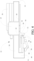
- the length of the positioner/holder allows the user to position the array in selected set positions, as exemplified by the transducer positions in FIGs. 2 and 3 and FIGs. 4 and 5 respectively, that are designed to ensure overlap between scans so that there is no missing data. This feature is analogous to the use of overlapping scans with a mechanical x-y gantry system.
- Scanning is accomplished by translation of the positioner/holder 22 longitudinally along the T-chord.
- Rollers 34 on a lower surface 36 of the support piers 23 extending from the support rail 24 provide low friction engagement of a top surface 38 of the T-chord (seen in FIG. 2 and 4 ). Bearings or rollers may alternatively be contained in the bottom surface of the support rail 24.
- Positioning rods 32 for the guide 28 are telescopically adjustable through bores 40 in the base 31. Set screws 42 (best seen in FIGs. 6 and 70 are employed to lock the positioning rods at the desired extension.
- a rotary encoder assembly 44 flexibly extends from the base 31 to be positioned with an encoder wheel 46 on the inner flange 16 of the T-chord 10.
- a flexing scissor bracket 48 connects an encoder 50 such as an Olympus Mini-Wheel Encoder, to the base 31 for lateral positioning of the encoder wheel 46 adjacent any radius 52 between the web 12 and inner flange 16 and to resiliently urge the encoder wheel into engagement with the inner flange.
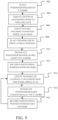
- FIG. 9 describes the method employed for implementing measurements using the embodiment as described.
- positioner/holder 22 is placed on the top surface 38 of the T-chord, step 902.
- Positioning rods 32 are adjusted in length from the near edge 30 to place the guide 28 against the surface 20 of the web 12 with clearance for the inner flange 16 for the longitudinal scan and locked in place using set screws 42, step 904.
- the rotary encoder assembly 44 is adjusted using flexing scissor bracket 48 to position the encoder wheel 46 on the inner flange 16 adjacent the radius 52 from the web to the inner flange, step 906.
- the transducer 26 is positioned at a first position on the support rail 24 (as shown in FIGs. 2 and 3 ) for a first longitudinal scan, step 908.
- the positioner/holder 22 is then translated along the length of the T-chord, step 910. Longitudinal position of the positioner/holder 22 during the scan is recorded by the rotary encoder 50 for correlation of the data provided by the ultrasonic array in the transducer, step 912.
- the transducer 26 is then adjusted laterally on the support rail 24 for an overlapping scan, step 914.
- the positioner/holder 22 is again translated along the length of the T-chord, step 916, and the longitudinal position of the positioner/holder 22 during the scan is recorded by the rotary encoder 50 for correlation of the data provided by the ultrasonic array in the transducer. Steps 914, 916 and 918 may be repeated multiple times for wide flange sizes or overlapped scans as desired.
Landscapes
- Physics & Mathematics (AREA)
- Health & Medical Sciences (AREA)
- Life Sciences & Earth Sciences (AREA)
- Chemical & Material Sciences (AREA)
- Analytical Chemistry (AREA)
- Biochemistry (AREA)
- General Health & Medical Sciences (AREA)
- General Physics & Mathematics (AREA)
- Immunology (AREA)
- Pathology (AREA)
- Acoustics & Sound (AREA)
- Investigating Or Analyzing Materials By The Use Of Ultrasonic Waves (AREA)
Description
- Embodiments of the disclosure relate generally to the field of ultrasonic testing systems and more particularly to a manipulable holder for an ultrasonic array to accommodate scanning with the array on composite elements such as T-chords having flanges with cutouts and asymmetric geometry.
- Ultrasonic scanning of composite parts is a key quality control capability. Imaging of surfaces is best conducted with scans along the surface in a substantially linear fashion. Where the ultrasonic array is not as wide as the surface to be scanned, multiple passes along the surface are required. Recording of accurate position information of the array during the scan is critical to obtain desired data coverage. The complexity of many composite parts makes alignment of the array in multiple scans challenging. With parts such as T-chords, the cap flange is likely to be asymmetric and typically has cutouts to accommodate mating components or required pass-throughs. Previous solutions have used the edge of the part being scanned to position the transducer with wide bases that span the largest cut out on the part. In the case of the composite T-Chords, employing the edge of the part and using these design features would force the transducer to rotate at various angles as the transducer scans down the length of the part. When using a rotary encoder that tracks the linear position along the scan, these non-normal angles of the transducer to the scan direction lead to positional errors in the ultrasonic data shown in the C Scan.
- It is therefore desirable to provide a holder and guide for ultrasonic transducer arrays which provides accurate scanning placement for the array and further provides accurate position data for correlation of images taken during scanning.
-
US 2011/0178727 A1 in accordance with its abstract states an "Apparatus for nondestructive inspection of structural elements or workpieces, in particular those having an airfoil configuration, that moves a scanning sensor across the width (span) of a structural element or workpiece for the purpose of detecting structural damage. In one embodiment, the apparatus simultaneously traverses the length (chord) of the structural element or workpiece. In another embodiment, the apparatus includes a guide rail that encompasses the structural element or workpiece and the scanning sensor travels along the guide rail from a first location at an upper rear region, to the front, of the structural element or workpiece, and then around the leading edge toward the lower rear region. The apparatus includes a processor and a display device to display the processed, sensed, information.". -
JP H05 209869 A - In an aspect, there is provided an ultrasonic inspection device for inspection of a T-chord, wherein the T-chord is a composite part and comprises a web, and a cap on the web, the cap having two flanges, the ultrasonic inspection device as defined in claim 1.
- In another aspect, there is provided a method for ultrasonic inspection of a T-chord, wherein the T-chord is a composite part and comprises a web, and a cap having two flanges, the method as defined in claim 5.
- The features, functions, and advantages that have been discussed can be achieved independently in various embodiments of the present disclosure or may be combined in yet other embodiments further details of which can be seen with reference to the following description and drawings.
-
-
FIG. 1A is a top view of an exemplary T-chord on which the embodiments disclosed herein may be employed; -
FIG. 1B is a side section view of the T-chord ofFIG. 1A ; -
FIG. 2 is a front view of an example embodiment engaged to a T-chord with the transducer array in a first scan position; -
FIG. 3 is a top view of the embodiment; -
FIG. 4 is a front view of the embodiment with the transducer array in a second scan position; -
FIG. 5 is a top view of the embodiment with the transducer array in the second scan position; -
FIG. 6 is a lower isometric view of the embodiment with the T-chord removed; -
FIG. 7 is a bottom view of the embodiment with the T-chord removed; -
FIG. 8 is a detailed view of the position encoder assembly; and, -
FIG. 9 is a flow chart showing operation of the embodiment for a C-scan of a T-chord. - Embodiments disclosed herein provide a transducer incorporating an ultrasonic array and a positioner/holder having a base with a rail extending from the base to support the transducer in at least two lateral positions. A guide extends from the base for contact with a web of a composite shape. The guide maintains the rail substantially perpendicular to the web. An encoder is supported by the base and contacts a flange of the composite shape. The positioner/holder is adapted for longitudinal motion along the composite shape to create C-scans with the transducer without being impacted by asymmetric or irregular flange shapes or cutouts.
- An example composite part on which the present embodiments may be employed is a T-
chord 10 shown inFIGs. 1A and1B . The T-chord has aweb 12 and acap 14 having aninner flange 16 andouter flange 18. A datum in the design of T-chords is asurface 20 of theweb 12. - An example embodiment of a transducer positioner/
holder 22 as shown inFIGs. 2 through 7 employs asupport rail 24 for atransducer 26 housing an ultrasonic array, such as a 3.5L128-NW3 linear transducer from Olympus 48 Woerd Ave, Waltham, MA 02453, to obtain C-scan data. Aguide 28 which rides on thesurface 20 of theweb 12 is used to position anear edge 30 of abase 31 of the transducer positioner/holder 22 a set distance laterally from the web. The positioner/holder 22 holds thetranducer 26 normal to the web as the transducer positioner/holder is scanned longitudinally along the part. Theguide 28 extends from thenear edge 30 mounted onpositioning rods 32 extending from thebase 31. Theguide 28 is dimensioned longitudinally (along the web) with sufficient length to provide stable perpendicularity of thesupport rail 24 relative to the web during the longitudinal scan.Wheels 29 or similar bearing elements extending from the guide 28 (best seen inFIG. 6 ) provide low friction engagement onsurface 20 of theweb 12. Positioning thetransducer 26 to be normal to the scan direction avoids positional errors in the ultrasonic data that may lead to indications being hidden or incorrectly sized in the C-scan presentation. - The
ultrasonic array transducer 26 is adjustable on thesupport rail 24 for placement at different lateral positions along the length of the positioner/holder 22. Set screws, spring loaded detents or similar locking mechanisms may be employed to secure the transducer in position on the rail. In the embodiment in the drawings, anaperture 25 in the support rail provides a clear field for the acoustic array to interrogate the composite part being scanned.Support piers 23 extend from thesupport rail 24 substantially opposite the web of the T-chord being measured. The support piers may be movable with respect to the support rail for adjustment with respect to web location for differing T-chord profiles. In alternative embodiments,high friction rollers 27 or similar devices in the support piers may be employed to resistively secure the transducer against unwanted lateral motion yet allow desired positioning. The length of the positioner/holder allows the user to position the array in selected set positions, as exemplified by the transducer positions inFIGs. 2 and3 andFIGs. 4 and5 respectively, that are designed to ensure overlap between scans so that there is no missing data. This feature is analogous to the use of overlapping scans with a mechanical x-y gantry system. - Scanning is accomplished by translation of the positioner/
holder 22 longitudinally along the T-chord.Rollers 34 on alower surface 36 of thesupport piers 23 extending from the support rail 24 (seen best inFIG.7 ) provide low friction engagement of atop surface 38 of the T-chord (seen inFIG. 2 and4 ). Bearings or rollers may alternatively be contained in the bottom surface of the support rail 24.Positioning rods 32 for theguide 28 are telescopically adjustable through bores 40 in thebase 31. Set screws 42 (best seen inFIGs. 6 and 70 are employed to lock the positioning rods at the desired extension. - A
rotary encoder assembly 44 flexibly extends from the base 31 to be positioned with anencoder wheel 46 on theinner flange 16 of the T-chord 10. A flexingscissor bracket 48 connects anencoder 50 such as an Olympus Mini-Wheel Encoder, to thebase 31 for lateral positioning of theencoder wheel 46 adjacent anyradius 52 between theweb 12 andinner flange 16 and to resiliently urge the encoder wheel into engagement with the inner flange. -
FIG. 9 describes the method employed for implementing measurements using the embodiment as described. In operation, positioner/holder 22 is placed on thetop surface 38 of the T-chord,step 902. Positioningrods 32 are adjusted in length from thenear edge 30 to place theguide 28 against thesurface 20 of theweb 12 with clearance for theinner flange 16 for the longitudinal scan and locked in place usingset screws 42,step 904. Therotary encoder assembly 44 is adjusted using flexingscissor bracket 48 to position theencoder wheel 46 on theinner flange 16 adjacent theradius 52 from the web to the inner flange,step 906. Thetransducer 26 is positioned at a first position on the support rail 24 (as shown inFIGs. 2 and3 ) for a first longitudinal scan,step 908. The positioner/holder 22 is then translated along the length of the T-chord,step 910. Longitudinal position of the positioner/holder 22 during the scan is recorded by therotary encoder 50 for correlation of the data provided by the ultrasonic array in the transducer,step 912. Thetransducer 26 is then adjusted laterally on thesupport rail 24 for an overlapping scan,step 914. The positioner/holder 22 is again translated along the length of the T-chord,step 916, and the longitudinal position of the positioner/holder 22 during the scan is recorded by therotary encoder 50 for correlation of the data provided by the ultrasonic array in the transducer.Steps - Having now described various embodiments of the disclosure in detail as required by the patent statutes, those skilled in the art will recognize modifications and substitutions to the specific embodiments disclosed herein. Such modifications are within the scope of the present disclosure as defined in the following claims.
Claims (6)
- An ultrasonic inspection device for inspection of a T-chord (10), wherein the T-chord (10) is a composite part and comprises a web (12), and a cap (14) on the web (12), the cap (14) having two flanges (16, 18), the ultrasonic inspection device comprising:a transducer (26) incorporating an ultrasonic array;a positioner/holder (22) havinga base (31);a rail (24) extending from the base (31) to support the transducer (26) in at least two lateral positions;a guide (28) extending from the base (31) and arranged to contact the web (12), said guide (28) maintaining the rail (24) substantially perpendicular to the web (12), wherein
the guide (28) is supported from the base (31) by at least one adjustable length positioning rod (32), wherein
the at least one adjustable length positioning rod (32) is adjustable in length from a near edge (30) of the base (31) to place the guide (28) against a surface (20) of the web (12);an encoder (50) supported by the base (31) and contacting a flange (16);said positioner/holder (22) adapted for longitudinal motion along the T-chord (10); andsupport piers (23) extending from the rail (24) and incorporating wheels (29) riding on and aligned longitudinally with a top surface (38) of the cap (14). - The ultrasonic inspection device as defined in claim 1 wherein the encoder (50) employs an encoder wheel (46) riding on a lower surface (36) of the flange (16).
- The ultrasonic inspection device as defined in claim 2 wherein the encoder (50) is connected to the base (31) with an adjustable scissor bracket (48), said scissor bracket (48) positioning the encoder wheel (46) adjacent the web (12) clear of a radius (52).
- The ultrasonic inspection device as defined in claim 1 wherein the support piers (23) are movable with respect to the rail (24) to be positioned substantially opposite the web (12).
- A method for ultrasonic inspection of a T-chord (10), wherein the T-chord (10) is a composite part and comprises a web (12), and a cap (14) having two flanges (16, 18), the method comprising:providing a positioner/holder (22) having a base (31);mounting an ultrasonic transducer on a rail (24) extending from the base (31) of the positioner/holder (22) to support the transducer in at least two lateral positions;positioning the positioner/holder (22) with a guide (28) for contact with the web (12) on the T-chord (10), wherein
the guide (28) extends from the base (31) and is supported from the base (31) by at least one adjustable length positioning rod (32), wherein
the at least one adjustable length positioning rod (32) is adjustable in length from a near edge (30) of the base (31) to place the guide (28) against a surface (20) of the web (12), the guide maintaining the rail (24) substantially perpendicular to the web (12);translating the positioner/holder (22) longitudinally along the T-chord (10) with the ultrasonic transducer in a first lateral position on the rail (24);encoding the longitudinal position of the positioner/holder (22) during the longitudinal translation with an encoder wheel (46) engaging a flange (16) of the T-chord (10);moving the ultrasonic transducer to a second lateral position on the rail (24);repeating the longitudinal translation of the positioner/holder (22) along the T-chord (10); andencoding the longitudinal position of the positioner/holder (22) with the encoder wheel (46) during the repeating longitudinal translation. - The method of claim 5 further comprising:moving the ultrasonic transducer to additional lateral positions on the rail (24); andrepeating the longitudinal translation of the positioner/holder (22) along the T-chord (10); and,encoding the longitudinal position of the positioner/holder (22) with the encoder (46) wheel during the repeating longitudinal translation.
Applications Claiming Priority (1)
| Application Number | Priority Date | Filing Date | Title |
|---|---|---|---|
| US13/601,612 US20140060197A1 (en) | 2012-08-31 | 2012-08-31 | Ultrasonic array transducer holder and guide for flanges having cutouts and asymmetric geometry |
Publications (2)
| Publication Number | Publication Date |
|---|---|
| EP2703807A1 EP2703807A1 (en) | 2014-03-05 |
| EP2703807B1 true EP2703807B1 (en) | 2023-11-01 |
Family
ID=49054413
Family Applications (1)
| Application Number | Title | Priority Date | Filing Date |
|---|---|---|---|
| EP13182108.4A Active EP2703807B1 (en) | 2012-08-31 | 2013-08-28 | Ultrasonic array transducer holder and guide for flanges having cutouts and asymmetric geometry |
Country Status (2)
| Country | Link |
|---|---|
| US (1) | US20140060197A1 (en) |
| EP (1) | EP2703807B1 (en) |
Families Citing this family (2)
| Publication number | Priority date | Publication date | Assignee | Title |
|---|---|---|---|---|
| WO2017055435A1 (en) * | 2015-09-29 | 2017-04-06 | Institut National De La Sante Et De La Recherche Medicale (Inserm) | Method for determining a property of an object and associated device |
| CN106248791A (en) * | 2016-08-22 | 2016-12-21 | 合肥德泰科通测控技术有限公司 | A kind of method of metallic conduit ultrasonic listening slight crack |
Family Cites Families (13)
| Publication number | Priority date | Publication date | Assignee | Title |
|---|---|---|---|---|
| US5031458A (en) * | 1987-05-22 | 1991-07-16 | The Boeing Company | Portable ultrasonic inspection probe for laminated structures |
| JP2535550Y2 (en) * | 1990-06-05 | 1997-05-14 | 三菱重工業株式会社 | Underwater mobile inspection system |
| JP3036714B2 (en) * | 1992-01-31 | 2000-04-24 | 川崎製鉄株式会社 | Self-propelled flaw detector for thick plates |
| US5698787A (en) * | 1995-04-12 | 1997-12-16 | Mcdonnell Douglas Corporation | Portable laser/ultrasonic method for nondestructive inspection of complex structures |
| CN1089049C (en) * | 1996-03-22 | 2002-08-14 | 波音公司 | Aircraft wing spar, method of assembling aircraft wing spar and chord positioning tool |
| US6658939B2 (en) * | 2000-01-28 | 2003-12-09 | The Boeing Company | Fixture for automated ultrasonic scanning of radii in aerospace structure |
| US7444876B2 (en) * | 2005-08-26 | 2008-11-04 | The Boeing Company | Rapid prototype integrated linear ultrasonic transducer inspection apparatus, systems, and methods |
| US7617732B2 (en) * | 2005-08-26 | 2009-11-17 | The Boeing Company | Integrated curved linear ultrasonic transducer inspection apparatus, systems, and methods |
| US7975549B2 (en) * | 2007-06-19 | 2011-07-12 | The Boeing Company | Method, apparatus and system for inspecting a workpiece having a curved surface |
| US7644618B2 (en) * | 2007-10-26 | 2010-01-12 | The Boeing Company | Apparatus and method for nondestructive inspection of parts |
| US8082793B2 (en) * | 2008-10-16 | 2011-12-27 | The Boeing Company | Adjustable probe for ultrasonic testing |
| US8347746B2 (en) * | 2010-01-19 | 2013-01-08 | The Boeing Company | Crawling automated scanner for non-destructive inspection of aerospace structural elements |
| ITTO20101090A1 (en) * | 2010-12-30 | 2012-07-01 | Alenia Aeronautica Spa | ULTRASONIC NON-DESTRUCTIVE INSPECTION METHOD, IN PARTICULAR FOR COMPOSITE MATERIAL STRUCTURES FOR AERONAUTICAL APPLICATIONS |
-
2012
- 2012-08-31 US US13/601,612 patent/US20140060197A1/en not_active Abandoned
-
2013
- 2013-08-28 EP EP13182108.4A patent/EP2703807B1/en active Active
Also Published As
| Publication number | Publication date |
|---|---|
| US20140060197A1 (en) | 2014-03-06 |
| EP2703807A1 (en) | 2014-03-05 |
Similar Documents
| Publication | Publication Date | Title |
|---|---|---|
| US7950297B2 (en) | Nondestructive inspection heads for components having limited surrounding space | |
| EP3077807B1 (en) | System and method for inspection of components | |
| US7075296B2 (en) | Inspection carriage for turbine blades | |
| JP5294773B2 (en) | Inspection device for concave surface of rotor disk | |
| EP3043176B1 (en) | Portable ultrasonic flow detection device and ultrasonic flow detection method | |
| KR101710573B1 (en) | Ultrasonic Inspection apparatus equipped with Variable extension 2-axis rail | |
| EP2703807A1 (en) | Ultrasonic array transducer holder and guide for flanges having cutouts and asymmetric geometry | |
| JP5181298B2 (en) | Metal material defect inspection system | |
| JP2006003164A (en) | Tool for measuring peripheral face shape of roll type article | |
| JPH1181935A (en) | Method and apparatus for measuring shape of seat surface in valve seat | |
| CN103017661A (en) | Lead screw detector and detection method using lead screw detector | |
| JP6875192B2 (en) | Local water immersion type ultrasonic flaw detector and method | |
| CN102279221A (en) | Nondestructive robotic inspection method and system therefor | |
| JP2003057215A (en) | Automatic ultrasonic flaw detection method and apparatus of welded section | |
| US20070096728A1 (en) | Eddy current inspection apparatus and methods | |
| JPH03272462A (en) | Driving apparatus for ultrasonic probe | |
| JP2007198822A (en) | Method of measuring rolling surface hardening depth of wheel bearing outer race | |
| JP2005300363A (en) | Ultrasonic flaw detection system and ultrasonic flaw detection test method | |
| KR100199442B1 (en) | Three dimension form inviting method and its device in overhead crane | |
| JP2018185232A (en) | Ultrasonic flaw detector of fiber-reinforced resin leaf spring | |
| JP2005181023A (en) | Apparatus and method for measuring height difference and inclination angle between planes | |
| JP6674835B2 (en) | Nuclear pressure vessel seat inspection system | |
| CN116923477B (en) | Track detection unit and detection equipment | |
| JP3665920B2 (en) | Remote nondestructive inspection equipment | |
| CN110018243A (en) | A kind of automatic scanning device for transversal crack |
Legal Events
| Date | Code | Title | Description |
|---|---|---|---|
| 17P | Request for examination filed |
Effective date: 20130828 |
|
| AK | Designated contracting states |
Kind code of ref document: A1 Designated state(s): AL AT BE BG CH CY CZ DE DK EE ES FI FR GB GR HR HU IE IS IT LI LT LU LV MC MK MT NL NO PL PT RO RS SE SI SK SM TR |
|
| AX | Request for extension of the european patent |
Extension state: BA ME |
|
| PUAI | Public reference made under article 153(3) epc to a published international application that has entered the european phase |
Free format text: ORIGINAL CODE: 0009012 |
|
| STAA | Information on the status of an ep patent application or granted ep patent |
Free format text: STATUS: EXAMINATION IS IN PROGRESS |
|
| 17Q | First examination report despatched |
Effective date: 20190308 |
|
| GRAP | Despatch of communication of intention to grant a patent |
Free format text: ORIGINAL CODE: EPIDOSNIGR1 |
|
| STAA | Information on the status of an ep patent application or granted ep patent |
Free format text: STATUS: GRANT OF PATENT IS INTENDED |
|
| INTG | Intention to grant announced |
Effective date: 20230109 |
|
| RAP3 | Party data changed (applicant data changed or rights of an application transferred) |
Owner name: THE BOEING COMPANY |
|
| GRAJ | Information related to disapproval of communication of intention to grant by the applicant or resumption of examination proceedings by the epo deleted |
Free format text: ORIGINAL CODE: EPIDOSDIGR1 |
|
| STAA | Information on the status of an ep patent application or granted ep patent |
Free format text: STATUS: EXAMINATION IS IN PROGRESS |
|
| INTC | Intention to grant announced (deleted) | ||
| GRAP | Despatch of communication of intention to grant a patent |
Free format text: ORIGINAL CODE: EPIDOSNIGR1 |
|
| STAA | Information on the status of an ep patent application or granted ep patent |
Free format text: STATUS: GRANT OF PATENT IS INTENDED |
|
| INTG | Intention to grant announced |
Effective date: 20230515 |
|
| RIN1 | Information on inventor provided before grant (corrected) |
Inventor name: FETZER, BARRY A. Inventor name: ANDERSON, PATRICK L. |
|
| GRAS | Grant fee paid |
Free format text: ORIGINAL CODE: EPIDOSNIGR3 |
|
| GRAA | (expected) grant |
Free format text: ORIGINAL CODE: 0009210 |
|
| STAA | Information on the status of an ep patent application or granted ep patent |
Free format text: STATUS: THE PATENT HAS BEEN GRANTED |
|
| AK | Designated contracting states |
Kind code of ref document: B1 Designated state(s): AL AT BE BG CH CY CZ DE DK EE ES FI FR GB GR HR HU IE IS IT LI LT LU LV MC MK MT NL NO PL PT RO RS SE SI SK SM TR |
|
| REG | Reference to a national code |
Ref country code: GB Ref legal event code: FG4D |
|
| REG | Reference to a national code |
Ref country code: CH Ref legal event code: EP |
|
| REG | Reference to a national code |
Ref country code: DE Ref legal event code: R096 Ref document number: 602013084874 Country of ref document: DE |
|
| P01 | Opt-out of the competence of the unified patent court (upc) registered |
Effective date: 20231012 |
|
| REG | Reference to a national code |
Ref country code: IE Ref legal event code: FG4D |
|
| REG | Reference to a national code |
Ref country code: LT Ref legal event code: MG9D |
|
| REG | Reference to a national code |
Ref country code: NL Ref legal event code: MP Effective date: 20231101 |
|
| PG25 | Lapsed in a contracting state [announced via postgrant information from national office to epo] |
Ref country code: GR Free format text: LAPSE BECAUSE OF FAILURE TO SUBMIT A TRANSLATION OF THE DESCRIPTION OR TO PAY THE FEE WITHIN THE PRESCRIBED TIME-LIMIT Effective date: 20240202 |
|
| PG25 | Lapsed in a contracting state [announced via postgrant information from national office to epo] |
Ref country code: IS Free format text: LAPSE BECAUSE OF FAILURE TO SUBMIT A TRANSLATION OF THE DESCRIPTION OR TO PAY THE FEE WITHIN THE PRESCRIBED TIME-LIMIT Effective date: 20240301 |
|
| PG25 | Lapsed in a contracting state [announced via postgrant information from national office to epo] |
Ref country code: LT Free format text: LAPSE BECAUSE OF FAILURE TO SUBMIT A TRANSLATION OF THE DESCRIPTION OR TO PAY THE FEE WITHIN THE PRESCRIBED TIME-LIMIT Effective date: 20231101 |
|
| REG | Reference to a national code |
Ref country code: AT Ref legal event code: MK05 Ref document number: 1627765 Country of ref document: AT Kind code of ref document: T Effective date: 20231101 |
|
| PG25 | Lapsed in a contracting state [announced via postgrant information from national office to epo] |
Ref country code: NL Free format text: LAPSE BECAUSE OF FAILURE TO SUBMIT A TRANSLATION OF THE DESCRIPTION OR TO PAY THE FEE WITHIN THE PRESCRIBED TIME-LIMIT Effective date: 20231101 |
|
| PG25 | Lapsed in a contracting state [announced via postgrant information from national office to epo] |
Ref country code: AT Free format text: LAPSE BECAUSE OF FAILURE TO SUBMIT A TRANSLATION OF THE DESCRIPTION OR TO PAY THE FEE WITHIN THE PRESCRIBED TIME-LIMIT Effective date: 20231101 |
|
| PG25 | Lapsed in a contracting state [announced via postgrant information from national office to epo] |
Ref country code: ES Free format text: LAPSE BECAUSE OF FAILURE TO SUBMIT A TRANSLATION OF THE DESCRIPTION OR TO PAY THE FEE WITHIN THE PRESCRIBED TIME-LIMIT Effective date: 20231101 |
|
| PG25 | Lapsed in a contracting state [announced via postgrant information from national office to epo] |
Ref country code: NL Free format text: LAPSE BECAUSE OF FAILURE TO SUBMIT A TRANSLATION OF THE DESCRIPTION OR TO PAY THE FEE WITHIN THE PRESCRIBED TIME-LIMIT Effective date: 20231101 Ref country code: LT Free format text: LAPSE BECAUSE OF FAILURE TO SUBMIT A TRANSLATION OF THE DESCRIPTION OR TO PAY THE FEE WITHIN THE PRESCRIBED TIME-LIMIT Effective date: 20231101 Ref country code: IS Free format text: LAPSE BECAUSE OF FAILURE TO SUBMIT A TRANSLATION OF THE DESCRIPTION OR TO PAY THE FEE WITHIN THE PRESCRIBED TIME-LIMIT Effective date: 20240301 Ref country code: GR Free format text: LAPSE BECAUSE OF FAILURE TO SUBMIT A TRANSLATION OF THE DESCRIPTION OR TO PAY THE FEE WITHIN THE PRESCRIBED TIME-LIMIT Effective date: 20240202 Ref country code: ES Free format text: LAPSE BECAUSE OF FAILURE TO SUBMIT A TRANSLATION OF THE DESCRIPTION OR TO PAY THE FEE WITHIN THE PRESCRIBED TIME-LIMIT Effective date: 20231101 Ref country code: BG Free format text: LAPSE BECAUSE OF FAILURE TO SUBMIT A TRANSLATION OF THE DESCRIPTION OR TO PAY THE FEE WITHIN THE PRESCRIBED TIME-LIMIT Effective date: 20240201 Ref country code: AT Free format text: LAPSE BECAUSE OF FAILURE TO SUBMIT A TRANSLATION OF THE DESCRIPTION OR TO PAY THE FEE WITHIN THE PRESCRIBED TIME-LIMIT Effective date: 20231101 Ref country code: PT Free format text: LAPSE BECAUSE OF FAILURE TO SUBMIT A TRANSLATION OF THE DESCRIPTION OR TO PAY THE FEE WITHIN THE PRESCRIBED TIME-LIMIT Effective date: 20240301 |
|
| PG25 | Lapsed in a contracting state [announced via postgrant information from national office to epo] |
Ref country code: SE Free format text: LAPSE BECAUSE OF FAILURE TO SUBMIT A TRANSLATION OF THE DESCRIPTION OR TO PAY THE FEE WITHIN THE PRESCRIBED TIME-LIMIT Effective date: 20231101 Ref country code: RS Free format text: LAPSE BECAUSE OF FAILURE TO SUBMIT A TRANSLATION OF THE DESCRIPTION OR TO PAY THE FEE WITHIN THE PRESCRIBED TIME-LIMIT Effective date: 20231101 Ref country code: PL Free format text: LAPSE BECAUSE OF FAILURE TO SUBMIT A TRANSLATION OF THE DESCRIPTION OR TO PAY THE FEE WITHIN THE PRESCRIBED TIME-LIMIT Effective date: 20231101 Ref country code: NO Free format text: LAPSE BECAUSE OF FAILURE TO SUBMIT A TRANSLATION OF THE DESCRIPTION OR TO PAY THE FEE WITHIN THE PRESCRIBED TIME-LIMIT Effective date: 20240201 Ref country code: LV Free format text: LAPSE BECAUSE OF FAILURE TO SUBMIT A TRANSLATION OF THE DESCRIPTION OR TO PAY THE FEE WITHIN THE PRESCRIBED TIME-LIMIT Effective date: 20231101 Ref country code: HR Free format text: LAPSE BECAUSE OF FAILURE TO SUBMIT A TRANSLATION OF THE DESCRIPTION OR TO PAY THE FEE WITHIN THE PRESCRIBED TIME-LIMIT Effective date: 20231101 |
|
| PG25 | Lapsed in a contracting state [announced via postgrant information from national office to epo] |
Ref country code: DK Free format text: LAPSE BECAUSE OF FAILURE TO SUBMIT A TRANSLATION OF THE DESCRIPTION OR TO PAY THE FEE WITHIN THE PRESCRIBED TIME-LIMIT Effective date: 20231101 |
|
| PG25 | Lapsed in a contracting state [announced via postgrant information from national office to epo] |
Ref country code: CZ Free format text: LAPSE BECAUSE OF FAILURE TO SUBMIT A TRANSLATION OF THE DESCRIPTION OR TO PAY THE FEE WITHIN THE PRESCRIBED TIME-LIMIT Effective date: 20231101 |
|
| PG25 | Lapsed in a contracting state [announced via postgrant information from national office to epo] |
Ref country code: SK Free format text: LAPSE BECAUSE OF FAILURE TO SUBMIT A TRANSLATION OF THE DESCRIPTION OR TO PAY THE FEE WITHIN THE PRESCRIBED TIME-LIMIT Effective date: 20231101 |
|
| PG25 | Lapsed in a contracting state [announced via postgrant information from national office to epo] |
Ref country code: SM Free format text: LAPSE BECAUSE OF FAILURE TO SUBMIT A TRANSLATION OF THE DESCRIPTION OR TO PAY THE FEE WITHIN THE PRESCRIBED TIME-LIMIT Effective date: 20231101 Ref country code: SK Free format text: LAPSE BECAUSE OF FAILURE TO SUBMIT A TRANSLATION OF THE DESCRIPTION OR TO PAY THE FEE WITHIN THE PRESCRIBED TIME-LIMIT Effective date: 20231101 Ref country code: RO Free format text: LAPSE BECAUSE OF FAILURE TO SUBMIT A TRANSLATION OF THE DESCRIPTION OR TO PAY THE FEE WITHIN THE PRESCRIBED TIME-LIMIT Effective date: 20231101 Ref country code: IT Free format text: LAPSE BECAUSE OF FAILURE TO SUBMIT A TRANSLATION OF THE DESCRIPTION OR TO PAY THE FEE WITHIN THE PRESCRIBED TIME-LIMIT Effective date: 20231101 Ref country code: EE Free format text: LAPSE BECAUSE OF FAILURE TO SUBMIT A TRANSLATION OF THE DESCRIPTION OR TO PAY THE FEE WITHIN THE PRESCRIBED TIME-LIMIT Effective date: 20231101 Ref country code: DK Free format text: LAPSE BECAUSE OF FAILURE TO SUBMIT A TRANSLATION OF THE DESCRIPTION OR TO PAY THE FEE WITHIN THE PRESCRIBED TIME-LIMIT Effective date: 20231101 Ref country code: CZ Free format text: LAPSE BECAUSE OF FAILURE TO SUBMIT A TRANSLATION OF THE DESCRIPTION OR TO PAY THE FEE WITHIN THE PRESCRIBED TIME-LIMIT Effective date: 20231101 |
|
| REG | Reference to a national code |
Ref country code: DE Ref legal event code: R097 Ref document number: 602013084874 Country of ref document: DE |
|
| PLBE | No opposition filed within time limit |
Free format text: ORIGINAL CODE: 0009261 |
|
| STAA | Information on the status of an ep patent application or granted ep patent |
Free format text: STATUS: NO OPPOSITION FILED WITHIN TIME LIMIT |
|
| 26N | No opposition filed |
Effective date: 20240802 |
|
| PG25 | Lapsed in a contracting state [announced via postgrant information from national office to epo] |
Ref country code: SI Free format text: LAPSE BECAUSE OF FAILURE TO SUBMIT A TRANSLATION OF THE DESCRIPTION OR TO PAY THE FEE WITHIN THE PRESCRIBED TIME-LIMIT Effective date: 20231101 |
|
| PG25 | Lapsed in a contracting state [announced via postgrant information from national office to epo] |
Ref country code: SI Free format text: LAPSE BECAUSE OF FAILURE TO SUBMIT A TRANSLATION OF THE DESCRIPTION OR TO PAY THE FEE WITHIN THE PRESCRIBED TIME-LIMIT Effective date: 20231101 |
|
| REG | Reference to a national code |
Ref country code: CH Ref legal event code: PL |
|
| PG25 | Lapsed in a contracting state [announced via postgrant information from national office to epo] |
Ref country code: LU Free format text: LAPSE BECAUSE OF NON-PAYMENT OF DUE FEES Effective date: 20240828 |
|
| PG25 | Lapsed in a contracting state [announced via postgrant information from national office to epo] |
Ref country code: MC Free format text: LAPSE BECAUSE OF FAILURE TO SUBMIT A TRANSLATION OF THE DESCRIPTION OR TO PAY THE FEE WITHIN THE PRESCRIBED TIME-LIMIT Effective date: 20231101 Ref country code: CH Free format text: LAPSE BECAUSE OF NON-PAYMENT OF DUE FEES Effective date: 20240831 |
|
| REG | Reference to a national code |
Ref country code: BE Ref legal event code: MM Effective date: 20240831 |
|
| PG25 | Lapsed in a contracting state [announced via postgrant information from national office to epo] |
Ref country code: BE Free format text: LAPSE BECAUSE OF NON-PAYMENT OF DUE FEES Effective date: 20240831 |
|
| PG25 | Lapsed in a contracting state [announced via postgrant information from national office to epo] |
Ref country code: IE Free format text: LAPSE BECAUSE OF NON-PAYMENT OF DUE FEES Effective date: 20240828 |
|
| PG25 | Lapsed in a contracting state [announced via postgrant information from national office to epo] |
Ref country code: FI Free format text: LAPSE BECAUSE OF FAILURE TO SUBMIT A TRANSLATION OF THE DESCRIPTION OR TO PAY THE FEE WITHIN THE PRESCRIBED TIME-LIMIT Effective date: 20231101 |
|
| PGFP | Annual fee paid to national office [announced via postgrant information from national office to epo] |
Ref country code: DE Payment date: 20250827 Year of fee payment: 13 |
|
| PGFP | Annual fee paid to national office [announced via postgrant information from national office to epo] |
Ref country code: GB Payment date: 20250827 Year of fee payment: 13 |
|
| PGFP | Annual fee paid to national office [announced via postgrant information from national office to epo] |
Ref country code: FR Payment date: 20250825 Year of fee payment: 13 |
|
| PG25 | Lapsed in a contracting state [announced via postgrant information from national office to epo] |
Ref country code: CY Free format text: LAPSE BECAUSE OF FAILURE TO SUBMIT A TRANSLATION OF THE DESCRIPTION OR TO PAY THE FEE WITHIN THE PRESCRIBED TIME-LIMIT; INVALID AB INITIO Effective date: 20130828 |
|
| PG25 | Lapsed in a contracting state [announced via postgrant information from national office to epo] |
Ref country code: HU Free format text: LAPSE BECAUSE OF FAILURE TO SUBMIT A TRANSLATION OF THE DESCRIPTION OR TO PAY THE FEE WITHIN THE PRESCRIBED TIME-LIMIT; INVALID AB INITIO Effective date: 20130828 |