EP2703638A1 - Ignition timing controller for internal combustion engine - Google Patents
Ignition timing controller for internal combustion engine Download PDFInfo
- Publication number
- EP2703638A1 EP2703638A1 EP12777410.7A EP12777410A EP2703638A1 EP 2703638 A1 EP2703638 A1 EP 2703638A1 EP 12777410 A EP12777410 A EP 12777410A EP 2703638 A1 EP2703638 A1 EP 2703638A1
- Authority
- EP
- European Patent Office
- Prior art keywords
- ignition timing
- optimal ignition
- engine
- fuel injection
- timing
- Prior art date
- Legal status (The legal status is an assumption and is not a legal conclusion. Google has not performed a legal analysis and makes no representation as to the accuracy of the status listed.)
- Granted
Links
Images



Classifications
-
- F—MECHANICAL ENGINEERING; LIGHTING; HEATING; WEAPONS; BLASTING
- F02—COMBUSTION ENGINES; HOT-GAS OR COMBUSTION-PRODUCT ENGINE PLANTS
- F02P—IGNITION, OTHER THAN COMPRESSION IGNITION, FOR INTERNAL-COMBUSTION ENGINES; TESTING OF IGNITION TIMING IN COMPRESSION-IGNITION ENGINES
- F02P5/00—Advancing or retarding ignition; Control therefor
- F02P5/04—Advancing or retarding ignition; Control therefor automatically, as a function of the working conditions of the engine or vehicle or of the atmospheric conditions
- F02P5/045—Advancing or retarding ignition; Control therefor automatically, as a function of the working conditions of the engine or vehicle or of the atmospheric conditions combined with electronic control of other engine functions, e.g. fuel injection
-
- F—MECHANICAL ENGINEERING; LIGHTING; HEATING; WEAPONS; BLASTING
- F02—COMBUSTION ENGINES; HOT-GAS OR COMBUSTION-PRODUCT ENGINE PLANTS
- F02P—IGNITION, OTHER THAN COMPRESSION IGNITION, FOR INTERNAL-COMBUSTION ENGINES; TESTING OF IGNITION TIMING IN COMPRESSION-IGNITION ENGINES
- F02P5/00—Advancing or retarding ignition; Control therefor
- F02P5/04—Advancing or retarding ignition; Control therefor automatically, as a function of the working conditions of the engine or vehicle or of the atmospheric conditions
- F02P5/145—Advancing or retarding ignition; Control therefor automatically, as a function of the working conditions of the engine or vehicle or of the atmospheric conditions using electrical means
- F02P5/15—Digital data processing
- F02P5/1502—Digital data processing using one central computing unit
-
- F—MECHANICAL ENGINEERING; LIGHTING; HEATING; WEAPONS; BLASTING
- F02—COMBUSTION ENGINES; HOT-GAS OR COMBUSTION-PRODUCT ENGINE PLANTS
- F02D—CONTROLLING COMBUSTION ENGINES
- F02D2200/00—Input parameters for engine control
- F02D2200/02—Input parameters for engine control the parameters being related to the engine
- F02D2200/06—Fuel or fuel supply system parameters
- F02D2200/0618—Actual fuel injection timing or delay, e.g. determined from fuel pressure drop
-
- F—MECHANICAL ENGINEERING; LIGHTING; HEATING; WEAPONS; BLASTING
- F02—COMBUSTION ENGINES; HOT-GAS OR COMBUSTION-PRODUCT ENGINE PLANTS
- F02D—CONTROLLING COMBUSTION ENGINES
- F02D2200/00—Input parameters for engine control
- F02D2200/02—Input parameters for engine control the parameters being related to the engine
- F02D2200/10—Parameters related to the engine output, e.g. engine torque or engine speed
- F02D2200/101—Engine speed
-
- F—MECHANICAL ENGINEERING; LIGHTING; HEATING; WEAPONS; BLASTING
- F02—COMBUSTION ENGINES; HOT-GAS OR COMBUSTION-PRODUCT ENGINE PLANTS
- F02D—CONTROLLING COMBUSTION ENGINES
- F02D41/00—Electrical control of supply of combustible mixture or its constituents
- F02D41/02—Circuit arrangements for generating control signals
- F02D41/18—Circuit arrangements for generating control signals by measuring intake air flow
-
- F—MECHANICAL ENGINEERING; LIGHTING; HEATING; WEAPONS; BLASTING
- F02—COMBUSTION ENGINES; HOT-GAS OR COMBUSTION-PRODUCT ENGINE PLANTS
- F02D—CONTROLLING COMBUSTION ENGINES
- F02D41/00—Electrical control of supply of combustible mixture or its constituents
- F02D41/24—Electrical control of supply of combustible mixture or its constituents characterised by the use of digital means
- F02D41/2406—Electrical control of supply of combustible mixture or its constituents characterised by the use of digital means using essentially read only memories
- F02D41/2409—Addressing techniques specially adapted therefor
- F02D41/2422—Selective use of one or more tables
-
- Y—GENERAL TAGGING OF NEW TECHNOLOGICAL DEVELOPMENTS; GENERAL TAGGING OF CROSS-SECTIONAL TECHNOLOGIES SPANNING OVER SEVERAL SECTIONS OF THE IPC; TECHNICAL SUBJECTS COVERED BY FORMER USPC CROSS-REFERENCE ART COLLECTIONS [XRACs] AND DIGESTS
- Y02—TECHNOLOGIES OR APPLICATIONS FOR MITIGATION OR ADAPTATION AGAINST CLIMATE CHANGE
- Y02T—CLIMATE CHANGE MITIGATION TECHNOLOGIES RELATED TO TRANSPORTATION
- Y02T10/00—Road transport of goods or passengers
- Y02T10/10—Internal combustion engine [ICE] based vehicles
- Y02T10/40—Engine management systems
Definitions
- the present invention relates to an ignition timing control apparatus for an internal combustion engine.
- an engine control apparatus In order to achieve optimum values for an ignition signal and a fuel injeetion signal of the engine, an engine control apparatus has been known in which the optimum ignition control data is stored in advance with respect to the various control information regarding the operating state of the engine, and in response to measurement data from an input measurement section and input data from the input section and the output information receiving section, by referring these input data to the optimum ignition control data, the corrected control data for the optimal ignition signal that corrects the measurement data is calculated (Patent Document 1).
- Patent Document Japanese Patent Application Publication No. H8-189449
- the objective of the present invention resides in providing an ignition timing control apparatus or system that can reduce the efforts (of fitting) to prepare a control map when obtaining an optimal ignition timing with respect to a fuel injection timing as well as decrease the calculation load associated.
- the present invention solves the problem described above by obtaining, at a current or actual engine rotation speed, a deviation between an optimal ignition timing with respect to a specific injection timing and an optimal ignition timing with respect to a current or actual fuel injection timing, and by obtaining a correction coefficient with respect to a current or actual engine load, to thereby obtain a variation or change amount in the optimal ignition timing based on the deviation in the optimal ignition timing and the correction coefficient.
- the calculation load when calculating the optimal ignition timing with respect to a fuel injection timing may be mitigated.
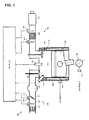
- Fig. 1 is a block diagram illustrating an internal combustion engine to which an embodiment of the present invention is applied. More specifically, the ignition timing control apparatus according to the present invention is now described as applied to a so-called in-cylinder, direct injection spark-ignition engine EG.
- an intake passage 111 of the engine EG is provided with an air filter 112, an air flowmeter 113 for detecting the intake air flow rate, a throttle valve 114 for controlling the intake air flow rate and a collector 115 throttle valve.
- the throttle valve 114 is provided with an actuator 116 such as a DC motor that adjusts the opening degree of the throttle valve 114.
- the throttle valve actuator 116 electronically controls the opening of the throttle valve 114 in response to a drive signal from the engine control unit 11 so as to achieve the required torque calculated based on the accelerator pedal operation amount of the driver.
- a throttle sensor 117 for detecting the opening of the throttle valve 114 is provided and its detection signal will be output to the engine control unit 1.
- the throttle sensor 117 can also serve as an idle switch.
- a fuel injection valve 118 is provided so as to face a combustion chamber 123.
- the fuel injection valve 118 is configured be subjected to a driving pulse signal set by the engine control unit 11 to be driven to open and inject directly into the cylinder a fuel that in turn is fed from a fuel pump (not shown) at a predetermined pressure by way of a pressure regulator.
- a combustion chamber 123 is defined by a space surrounded by a cylinder 119, a crown surface of a piston 120 reciprocally movable within the cylinder, a cylinder head provided with an intake valve 121 and an exhaust valve 122.
- a spark plug 124 is mounted to be exposed to the combustion chamber 123 and ignites an intake air-fuel mixture based on an ignition signal from the engine control unit 11.
- the present invention is intended to control the ignition signal to the ignition plug 124 so as to maximize the output torque in relation to the fuel injection timing of the fuel injection valve 118.
- an exhaust passage 125 is provided with an air-fuel ratio sensor for detecting an air-fuel ratio of the exhaust, thus of the intake air mixture by detecting an oxygen concentration and its detection signal is output to the engine control unit 11.
- the air-fuel ratio sensor 126 may be an oxygen sensor for a rich/lean output, or may be a broad air-fuel ratio sensor for detecting over an air-fuel ratio linearly over a wide range.
- the exhaust passage 125 is provided with an exhaust gas purifying catalyst 127 for purifying exhaust gas.
- an oxygen catalyst may be used for oxidizing hydrocarbons HC and carbon monoxide CO in the exhaust gas.
- an oxygen sensor 128 is provided to detect a specific component in the exhaust gas, for example, to detect the oxygen concentration so as to provide a rich/lean output.
- the detection signal is output to the engine control unit 11.
- a downstream side oxygen sensor 128 is provided such that a suppression on a control error caused by the deterioration of the exhaust purifying catalyst 127 and the like is achieved (so as to adopt a so-called double air-fuel ratio sensor system).
- the oxygen sensor 128 may be eliminated.
- 129 is a muffler in Figure 1 .
- a crankshaft 130 of the engine EG is provided with a crank angle sensor 131.
- the engine control unit 11 may detect an engine rotation speed Ne either by counting a unit crank angle signal over a predetermined time generated from the crank angle sensor 131 in synchronization with engine rotation or by measuring the period of the crank reference angle signal.
- a cooling jacket 132 of the engine EG is provided with a water temperature sensor 133 that is exposed to the cooling jacket for detecting and outputting a coolant temperature Tw of the cooling jacket 131 to the engine control unit 11.
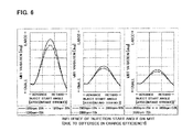
- Fig. 6 respectively show a graph which confirmed experimentally the relationship between the fuel injection timing (shown by a fuel injection start angle of the horizontal axis (degATDC)) and an optimal ignition timing (shown by a MBT variation or change amount in the vertical axis) when the engine rotation speed is set to 1200rpm (left), 2800rpm (central figure), 3600rpm (right) while setting an engine load at 25%, 50% and 75% (shown by an engine charging efficiency (%)) at each engine rotation speed fuel injection start angle (indicated by degATDC)), According to the results of the figure, along with the change in engine load, the variation or change amount of the optimum ignition timing is increased as the engine load is lower.
- degATDC fuel injection start angle of the horizontal axis
- the fuel injection timing at which the variations of the optimal ignition timing becomes a peal is about the same. Further, despite the change in engine rotation speed, the variation in the optimal ignition timing with respect to the engine load is substantially the same. In other words, although the absolute value of the optimal ignition timing may change in response to the change in engine load, the relative characteristic (profile) hardly change. Note that the crank angle range (deg) and load (charging efficiency %) in Figs. 5 , 6 are not necessarily identical.
- the optimum ignition timing with respect to the fuel injection timing may be affected by engine load and engine speed, but the degree of influence is different between the engine load and engine speed. That is, the present inventors have discovered that, while the influence of the optimum ignition timing with respect to the fuel injection timing due to the change in engine speed is complex, the influence to the optimal ignition timing with respect to a fuel injection timing due to change in engine load is relatively simple as compared to the change in engine speed. Moreover, based on these findings, when the control data is configured, the calculation load for the optimal ignition timing may be mitigated.
- the basic control data shown in Fig. 4 represents data obtained by an experiment or a computer simulation and shows an optimal ignition timing (indicated by a MBT equivalent line in the graph) with respect to an engine rotation speed (horizontal axis, rpm) of the engine EG and an engine load (charging efficiency (%) in the vertical axis) and may be configured as a control map.
- the specific fuel injection timing is not limited in particular, but may be set arbitrarily (In this embodiment, a constant fuel injection timing is set throughout the entire region of rotation speed and load).
- the equivalent lines in the figure indicates that the optimal ignition timing is delayed or retarded (see upper left of the graph) as the engine rotation speed is low and the engine load is high. Conversely, as the engine rotation speed increases and engine load decreases, the optimal ignition timing advances (see right lower portion of the graph). Note that the specific characteristic (profile of the equivalent lines) in the figure is only an example and does not pose any restriction on the present invention.
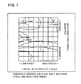
- the variation control data shown in Fig. 7 shows data obtained by an experiment or through a computer simulation regarding the (relative) variations or amount of change in the optimal ignition timing with respect to an engine rotation speed (rpm in horizontal axis) and a fuel injection timing (degATDC in the vertical axis) and may be configured as a control map, for example.
- the variations or change amount in the present embodiment correspond to the fuel injection start timing and the optimal ignition timing in crank degrees, "deg".
- the equivalent lines in the figure shows that the variations in the optimal ignition timing is smaller as the engine rotation speed is lower and the fuel injection timing is delayed or retarded (in the figure, indicated by "small” and thus relatively more retarded or delayed as compared to "large”).
- the correction coefficient control data shown in Fig. 8 is data obtained through experiments or computer simulation and represent a rate of variations in the optimal ignition timing with respect to an engine load while assuming the correction coefficient (gain) being "1" (i.e., correction amount is equal to "0") at a predetermined load when the variation control data shown in Fig. 7 has been acquired.
- a functional expression of an engine load and correction coefficient or rate may be used.
- the characteristic in the figure shows that the correction coefficient becomes smaller as the engine load is higher.
- the specific characteristic (profile) line in the figure is only an example and does not pose limitation on the present invention.
- the fuel injection timing at which the variation of the optimum ignition timing with respect to a change in engine load becomes the peak is about the same, and the movement of the variations in the optimal ignition timing with respect to engine load is about the same.
- the absolute value of the optimal ignition timing with respect to an engine load may change even at a change in engine rotation speed.
- the relative characteristic (profile) does not substantially change. Therefore, with respect to a current or actual engine load detected, by considering only a correction coefficient with respect to change in engine load, the calculation process may be simplified and the number of control maps may be reduced accordingly.
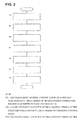
- FIG. 2 is a flowchart illustrating a procedure of ignition timing control executed by the engine controller 11.
- the engine rotation speed is detected by a crank angle sensor 131
- an engine load is detected by an accelerator opening sensor (not shown)
- a fuel injection timing is detected at predetermined time intervals from the control signal of the engine control unit 11.
- step ST1 by substituting or applying detected engine speed and detected engine load to the basic control data shown in FIG 4 , a basic optimum ignition timing at a specific injection timing is calculated, which is indicated by reference ST1 in Fig. 3 . Note that this step ST1 may be performed sometime before step ST7 so that it can be carried out immediately before step ST7, for example.
- step ST2 by applying the detected fuel injection timing as well as the detected engine rotation speed to the variation control data shown in Fig. 7 , a variation in the optimal ignition timing is calculated, which is indicated by reference ST2 in Fig. 3 .
- step ST3 by applying the specific fuel injection timing when the basic control data in Fig. 4 has been acquired and the detected engine rotation speed to the variation control data in Fig. 7 , a variation in optimal ignition timing is calculated, which is shown by reference ST3 in Fig. 3 .
- step ST4 by applying the detected engine load to the correction coefficient control data shown in Fig. 8 , a correction coefficient (gain) for a variation in optimal ignition timing is calculated, which is indicated by reference ST4 in Fig. 3 .
- step ST5 a deviation is calculated between the variation in the optimal ignition timing calculated in step ST2 and the variation in the optimal ignition timing calculated in step ST3, which is indicated by reference ST5 in Fig, 3 . Note that it is sufficient for this step ST5 to be performed somewhere between step ST3 and step ST6. Thus this step may be performed immediately after step ST3.
- step ST6 by multiplying the deviation of the variations in the basic optimal ignition timing as calculated in step ST1 by the correction coefficient (gain) calculated in step 4, an optimal ignition timing after correction is calculated in step ST6 the deviation of the variation in the optimum ignition timing calculated as indicated by reference ST6 in Fig. 3 .
- step ST7 by adding the basic optimum ignition timing calculated in step ST1 to the variation in the optimal ignition timing after correction, a final optimal ignition timing is calculated as indicated by reference ST7 in Fig. 3 .
- an optimal ignition timing control data ( Fig. 7 ) with respect to a fuel injection timing is required per the engine rotation speed.
- the variation in the optimal ignition timing may be corrected by a linear equation that calculates a correction coefficient of the optimal ignition timing with respect to change in engine load.
- the variation control data in Fig. 7 is set by a relative variation in the optimal ignition timing with respect to an engine rotation speed and a fuel injection timing.
- a deviation between variations is calculated, i.e. a deviation between the variation in the optimal ignition timing with respect to the detected injection timing and the variation in the optimal ignition timing with respect to the specific injection timing is calculated.
- the control data of the variation in the optimal ignition timing may be previously stored as a variation from the optimal ignition timing at a previously determined fuel injection timing, and by acquiring the variation in the optimal ignition timing based on the detected injection timing and the detected engine rotation speed, a deviation between the variations in the optimal ignition timing may be configured to be calculated.
- the control unit 11 corresponds to the injection timing detection unit or mechanism, storing unit or mechanism and control unit whereas the crank angle sensor corresponds to the rotation speed detection unit according to the present invention, and the accelerator pedal opening sensor not shown corresponds to a load detection unit according to the present invention.
Landscapes
- Engineering & Computer Science (AREA)
- Chemical & Material Sciences (AREA)
- Combustion & Propulsion (AREA)
- Mechanical Engineering (AREA)
- General Engineering & Computer Science (AREA)
- Theoretical Computer Science (AREA)
- Signal Processing (AREA)
- Combined Controls Of Internal Combustion Engines (AREA)
- Electrical Control Of Ignition Timing (AREA)
- Electrical Control Of Air Or Fuel Supplied To Internal-Combustion Engine (AREA)
Abstract
Description
- The present invention relates to an ignition timing control apparatus for an internal combustion engine.
- In order to achieve optimum values for an ignition signal and a fuel injeetion signal of the engine, an engine control apparatus has been known in which the optimum ignition control data is stored in advance with respect to the various control information regarding the operating state of the engine, and in response to measurement data from an input measurement section and input data from the input section and the output information receiving section, by referring these input data to the optimum ignition control data, the corrected control data for the optimal ignition signal that corrects the measurement data is calculated (Patent Document 1).
- Patent Document: Japanese Patent Application Publication No.
H8-189449 - However, in the engine control device of the prior art described above, it is necessary, when assuming two factors of engine load and engine speed as the control information regarding the engine, to prepare a plurality of control maps each corresponding to each injection timing. Thus, there is a problem involving an effort to prepare (to fit) a control map with the large calculation load associated.
- The objective of the present invention resides in providing an ignition timing control apparatus or system that can reduce the efforts (of fitting) to prepare a control map when obtaining an optimal ignition timing with respect to a fuel injection timing as well as decrease the calculation load associated.
- The present invention solves the problem described above by obtaining, at a current or actual engine rotation speed, a deviation between an optimal ignition timing with respect to a specific injection timing and an optimal ignition timing with respect to a current or actual fuel injection timing, and by obtaining a correction coefficient with respect to a current or actual engine load, to thereby obtain a variation or change amount in the optimal ignition timing based on the deviation in the optimal ignition timing and the correction coefficient.
- According to the present invention, based on the finding that the variations in the optimal ignition timing with respect to a fuel injection timing is affected by an engine rotation speed and engine load differently, and the optimal ignition timing with respect to an engine load is used as a correction coefficient, the calculation load when calculating the optimal ignition timing with respect to a fuel injection timing may be mitigated.
-
-
Fig. 1 is a block diagram illustrating an internal combustion engine to which an embodiment of the present invention is applied; -
Fig. 2 is a flowchart illustrating a procedure of ignition timing control executed by the engine control unit inFig. 1 ; -
Fig. 3 is a block diagram schematically showing the control procedure ofFig. 2 ; -
Fig. 4 is a control map showing an example of a basic control data stored in the engine control unit inFig. 1 ; -
Fig. 5 is a graph showing the relationship between the optimum ignition timing and fuel injection timing due to the change in engine rotation speed; -
Fig. 6 is a graph showing the relationship between the fuel injection timing and the optimum ignition timing due to the change in engine load; -
Fig. 7 is a control map showing an example of a change amount of the control data stored in the engine control unit inFig. 1 ; and -
Fig. 8 is a control map showing an example of the correction coefficient control data stored in the engine control unit inFig. 1 . -
Fig. 1 is a block diagram illustrating an internal combustion engine to which an embodiment of the present invention is applied. More specifically, the ignition timing control apparatus according to the present invention is now described as applied to a so-called in-cylinder, direct injection spark-ignition engine EG. - In
Fig. 1 , anintake passage 111 of the engine EG is provided with anair filter 112, anair flowmeter 113 for detecting the intake air flow rate, athrottle valve 114 for controlling the intake air flow rate and acollector 115 throttle valve. - The
throttle valve 114 is provided with anactuator 116 such as a DC motor that adjusts the opening degree of thethrottle valve 114. Thethrottle valve actuator 116 electronically controls the opening of thethrottle valve 114 in response to a drive signal from theengine control unit 11 so as to achieve the required torque calculated based on the accelerator pedal operation amount of the driver. Further, athrottle sensor 117 for detecting the opening of thethrottle valve 114 is provided and its detection signal will be output to the engine control unit 1. In addition, thethrottle sensor 117 can also serve as an idle switch. - A
fuel injection valve 118 is provided so as to face acombustion chamber 123. Thefuel injection valve 118 is configured be subjected to a driving pulse signal set by theengine control unit 11 to be driven to open and inject directly into the cylinder a fuel that in turn is fed from a fuel pump (not shown) at a predetermined pressure by way of a pressure regulator. - A
combustion chamber 123 is defined by a space surrounded by acylinder 119, a crown surface of apiston 120 reciprocally movable within the cylinder, a cylinder head provided with anintake valve 121 and anexhaust valve 122. Aspark plug 124 is mounted to be exposed to thecombustion chamber 123 and ignites an intake air-fuel mixture based on an ignition signal from theengine control unit 11. The present invention is intended to control the ignition signal to theignition plug 124 so as to maximize the output torque in relation to the fuel injection timing of thefuel injection valve 118. - Meanwhile, an
exhaust passage 125 is provided with an air-fuel ratio sensor for detecting an air-fuel ratio of the exhaust, thus of the intake air mixture by detecting an oxygen concentration and its detection signal is output to theengine control unit 11. The air-fuel ratio sensor 126 may be an oxygen sensor for a rich/lean output, or may be a broad air-fuel ratio sensor for detecting over an air-fuel ratio linearly over a wide range.. - Further, the
exhaust passage 125 is provided with an exhaust gas purifyingcatalyst 127 for purifying exhaust gas. As the exhaust gas purifyingcatalyst 127, a three-way catalyst may be used to purify the exhaust gas by performing the oxidation of hydrocarbons HC and carbon monoxide CO and the reduction of nitrogen oxides NOx in the exhaust in the vicinity of stoichiometric (stoichiometric air-fuel ratio, A = 1, the air weight / fuel weight = 14.7). Alternatively, an oxygen catalyst may be used for oxidizing hydrocarbons HC and carbon monoxide CO in the exhaust gas. - On the downstream side of the exhaust gas purifying
catalyst 127 of theexhaust passage 125, anoxygen sensor 128 is provided to detect a specific component in the exhaust gas, for example, to detect the oxygen concentration so as to provide a rich/lean output. The detection signal is output to theengine control unit 11. Note that, in accordance with the detection value of theoxygen sensor 128, by performing correction on the air-fuel feedback control based on the detection value of the air-fuel ratio sensor 126, a downstreamside oxygen sensor 128 is provided such that a suppression on a control error caused by the deterioration of the exhaust purifyingcatalyst 127 and the like is achieved (so as to adopt a so-called double air-fuel ratio sensor system). However, when it is sufficient to perform an air-fuel ratio feedback control only based on a detection value of the air-fuel sensor 126, theoxygen sensor 128 may be eliminated. - In addition, 129 is a muffler in
Figure 1 . - A
crankshaft 130 of the engine EG is provided with acrank angle sensor 131. Theengine control unit 11 may detect an engine rotation speed Ne either by counting a unit crank angle signal over a predetermined time generated from thecrank angle sensor 131 in synchronization with engine rotation or by measuring the period of the crank reference angle signal. - A
cooling jacket 132 of the engine EG is provided with awater temperature sensor 133 that is exposed to the cooling jacket for detecting and outputting a coolant temperature Tw of thecooling jacket 131 to theengine control unit 11. - Note that, in an in-cylinder direct-injection spark-ignition engine EG, when the ignition timing of the
ignition plug 124 is controlled to an optimal value in accordance with the fuel injection timing of thefuel injection valve 118, the output torque becomes maximum and a fuel efficiency is improved. The optimal ignition timing with respect to the fuel injection timing is largely affected by the operating state of the engine represented by the engine load and engine speed. -
Fig. 5 is a graph which confirmed experimentally the relationship between a fuel injection timing (shown by a fuel injection start angle in the horizontal axis (degATDC = indicated by a crank angle After Top Dead Center in the intake stroke) and the optimal ignition timing (indicated by the MBT (Maximum Brake Torque) variation or change amount in the vertical axis) when engine speed is subjected to 1200rpm, and 2800rpm, respectively. It can be seen that the characteristics of the optimum ignition timing for the fuel injection timing varies complicatedly due to change of the engine rotation speed. - Meanwhile,
Fig. 6 respectively show a graph which confirmed experimentally the relationship between the fuel injection timing (shown by a fuel injection start angle of the horizontal axis (degATDC)) and an optimal ignition timing (shown by a MBT variation or change amount in the vertical axis) when the engine rotation speed is set to 1200rpm (left), 2800rpm (central figure), 3600rpm (right) while setting an engine load at 25%, 50% and 75% (shown by an engine charging efficiency (%)) at each engine rotation speed fuel injection start angle (indicated by degATDC)), According to the results of the figure, along with the change in engine load, the variation or change amount of the optimum ignition timing is increased as the engine load is lower. However, at each engine load, the fuel injection timing at which the variations of the optimal ignition timing becomes a peal is about the same. Further, despite the change in engine rotation speed, the variation in the optimal ignition timing with respect to the engine load is substantially the same. In other words, although the absolute value of the optimal ignition timing may change in response to the change in engine load, the relative characteristic (profile) hardly change. Note that the crank angle range (deg) and load (charging efficiency %) inFigs. 5 ,6 are not necessarily identical. - Thus, although the optimum ignition timing with respect to the fuel injection timing may be affected by engine load and engine speed, but the degree of influence is different between the engine load and engine speed. That is, the present inventors have discovered that, while the influence of the optimum ignition timing with respect to the fuel injection timing due to the change in engine speed is complex, the influence to the optimal ignition timing with respect to a fuel injection timing due to change in engine load is relatively simple as compared to the change in engine speed. Moreover, based on these findings, when the control data is configured, the calculation load for the optimal ignition timing may be mitigated.
- Therefore, in the memory of the
engine control unit 11 according to the present embodiment, basic control data shown inFig. 4 , the variation control data shown inFig. 7 , and the correction coefficient control data shown inFig. 8 are stored, respectively. - The basic control data shown in
Fig. 4 represents data obtained by an experiment or a computer simulation and shows an optimal ignition timing (indicated by a MBT equivalent line in the graph) with respect to an engine rotation speed (horizontal axis, rpm) of the engine EG and an engine load (charging efficiency (%) in the vertical axis) and may be configured as a control map. The specific fuel injection timing is not limited in particular, but may be set arbitrarily (In this embodiment, a constant fuel injection timing is set throughout the entire region of rotation speed and load). The equivalent lines in the figure indicates that the optimal ignition timing is delayed or retarded (see upper left of the graph) as the engine rotation speed is low and the engine load is high. Conversely, as the engine rotation speed increases and engine load decreases, the optimal ignition timing advances (see right lower portion of the graph). Note that the specific characteristic (profile of the equivalent lines) in the figure is only an example and does not pose any restriction on the present invention. - The variation control data shown in
Fig. 7 shows data obtained by an experiment or through a computer simulation regarding the (relative) variations or amount of change in the optimal ignition timing with respect to an engine rotation speed (rpm in horizontal axis) and a fuel injection timing (degATDC in the vertical axis) and may be configured as a control map, for example. The variations or change amount in the present embodiment correspond to the fuel injection start timing and the optimal ignition timing in crank degrees, "deg". The equivalent lines in the figure shows that the variations in the optimal ignition timing is smaller as the engine rotation speed is lower and the fuel injection timing is delayed or retarded (in the figure, indicated by "small" and thus relatively more retarded or delayed as compared to "large"). On the other hand, the variations in the optimal ignition timing will be larger as the engine rotation speed is higher and the fuel injection timing is at the retard or delayed side (in the figure, indicated by "large" and thus relatively advanced as compared to "small"). Note that the specific characteristic in the figure (profile of the equivalent lines) is only an example and the no limitation is posed on the present invention. - The correction coefficient control data shown in
Fig. 8 is data obtained through experiments or computer simulation and represent a rate of variations in the optimal ignition timing with respect to an engine load while assuming the correction coefficient (gain) being "1" (i.e., correction amount is equal to "0") at a predetermined load when the variation control data shown inFig. 7 has been acquired. Instead of a control map shown, a functional expression of an engine load and correction coefficient or rate may be used. The characteristic in the figure shows that the correction coefficient becomes smaller as the engine load is higher. Note that the specific characteristic (profile) line in the figure is only an example and does not pose limitation on the present invention. - As described above, the fuel injection timing at which the variation of the optimum ignition timing with respect to a change in engine load becomes the peak is about the same, and the movement of the variations in the optimal ignition timing with respect to engine load is about the same. In other words, although the absolute value of the optimal ignition timing with respect to an engine load may change even at a change in engine rotation speed. Specifically, although the absolute value of the optimal ignition timing may vary in response to change of engine load, the relative characteristic (profile) does not substantially change. Therefore, with respect to a current or actual engine load detected, by considering only a correction coefficient with respect to change in engine load, the calculation process may be simplified and the number of control maps may be reduced accordingly.
- Now description is made of a control procedure.
Fig. 2 is a flowchart illustrating a procedure of ignition timing control executed by theengine controller 11. - In the following steps, the engine rotation speed is detected by a
crank angle sensor 131, an engine load is detected by an accelerator opening sensor (not shown), and a fuel injection timing is detected at predetermined time intervals from the control signal of theengine control unit 11. - First, in step ST1, by substituting or applying detected engine speed and detected engine load to the basic control data shown in
FIG 4 , a basic optimum ignition timing at a specific injection timing is calculated, which is indicated by reference ST1 inFig. 3 . Note that this step ST1 may be performed sometime before step ST7 so that it can be carried out immediately before step ST7, for example. - In step ST2, by applying the detected fuel injection timing as well as the detected engine rotation speed to the variation control data shown in
Fig. 7 , a variation in the optimal ignition timing is calculated, which is indicated by reference ST2 inFig. 3 . - In step ST3, by applying the specific fuel injection timing when the basic control data in
Fig. 4 has been acquired and the detected engine rotation speed to the variation control data inFig. 7 , a variation in optimal ignition timing is calculated, which is shown by reference ST3 inFig. 3 . - In step ST4, by applying the detected engine load to the correction coefficient control data shown in
Fig. 8 , a correction coefficient (gain) for a variation in optimal ignition timing is calculated, which is indicated by reference ST4 inFig. 3 . - In step ST5, a deviation is calculated between the variation in the optimal ignition timing calculated in step ST2 and the variation in the optimal ignition timing calculated in step ST3, which is indicated by reference ST5 in
Fig, 3 . Note that it is sufficient for this step ST5 to be performed somewhere between step ST3 and step ST6. Thus this step may be performed immediately after step ST3. - In step ST6, by multiplying the deviation of the variations in the basic optimal ignition timing as calculated in step ST1 by the correction coefficient (gain) calculated in step 4, an optimal ignition timing after correction is calculated in step ST6 the deviation of the variation in the optimum ignition timing calculated as indicated by reference ST6 in
Fig. 3 . - In step ST7, by adding the basic optimum ignition timing calculated in step ST1 to the variation in the optimal ignition timing after correction, a final optimal ignition timing is calculated as indicated by reference ST7 in
Fig. 3 . - As described above, according to the ignition timing control apparatus for an internal combustion engine according to the present embodiment, with respect to engine rotation speed, an optimal ignition timing control data (
Fig. 7 ) with respect to a fuel injection timing is required per the engine rotation speed. However, with respect to the detected engine load, since the variation in the optimal ignition timing may be corrected by a linear equation that calculates a correction coefficient of the optimal ignition timing with respect to change in engine load. Thus the necessity of referring to a plurality of control maps is removed so that the preparatory effort (for fitting process) of the control maps and the calculation load associated will be reduced. - In the illustrated embodiment, the variation control data in
Fig. 7 is set by a relative variation in the optimal ignition timing with respect to an engine rotation speed and a fuel injection timing. In addition, in step ST5 in the flowchart, a deviation between variations is calculated, i.e. a deviation between the variation in the optimal ignition timing with respect to the detected injection timing and the variation in the optimal ignition timing with respect to the specific injection timing is calculated. Alternatively, the control data of the variation in the optimal ignition timing may be previously stored as a variation from the optimal ignition timing at a previously determined fuel injection timing, and by acquiring the variation in the optimal ignition timing based on the detected injection timing and the detected engine rotation speed, a deviation between the variations in the optimal ignition timing may be configured to be calculated. - The
control unit 11 corresponds to the injection timing detection unit or mechanism, storing unit or mechanism and control unit whereas the crank angle sensor corresponds to the rotation speed detection unit according to the present invention, and the accelerator pedal opening sensor not shown corresponds to a load detection unit according to the present invention. -
- EG
- engine (internal combustion engine)
- 11
- engine control unit
- 111
- intake passage
- 112
- air filter
- 113
- air flow meter
- 114
- throttle valve
- 115
- collector
- 116
- throttle valve actuator
- 117
- throttle sensor
- 118
- fuel injection valve
- 119
- cylinder
- 120
- piston
- 121
- intake valve
- 122
- exhaust valve
- 123
- combustion chamber
- 124
- spark plug
- 125
- exhaust passage
- 126
- air-fuel ratio sensor
- 127
- exhaust purification catalyst
- 128
- oxygen sensor
- 129
- muffler
- 130
- crankshaft
- 131
- crank angle sensor
- 132
- cooling jacket
- 133
- water temperature sensor
Claims (3)
- An ignition timing control apparatus for a spark ignition internal combustion engine which injects fuel directly into a combustion chamber, comprising:an injection timing detection unit for detecting a fuel injection timing;a rotation speed detection unit for detecting an engine rotation speed,;a load detection unit for detecting an engine load;a storing unit for storing control data of variation in the optimal ignition timing with respect to an engine rotation speed and a fuel injection timing and control data of correction coefficient of the optimal ignition timing with respect to an engine load: anda control unit for obtaining an optimal ignition timing based on the fuel injection timing detected by the injection timing detection unit, the engine rotation speed detected by the rotation speed detection unit and the engine load detected by the load detection unit, whereinthe control unit acquires;
a variation in the optimal ignition timing based on the detected fuel injection timing and the detected engine rotation speed by referring to the control data;
a variation in the optimal ignition timing based on a previously determined, specific fuel injection timing and the detected engine rotation speed by referring to the control data;
a deviation between these variations of the optimal ignition timing;
a correction coefficient with respect to the detected engine load by referring to the control data of the correction coefficient; and
a variation in the optimal ignition timing after correction based on the deviation of the variations of the optimal ignition timing and the correction coefficient. - The ignition timing control apparatus for an internal combustion engine as claimed in claim 1, wherein
the control data of variations in the optimal ignition timing is stored as the variation from the optimal ignition timing at the previously determined, specific fuel injection timing, and
the control unit acquires the deviation of the variations in the optimal ignition timing by acquiring the variation based on the detected fuel injection timing and the detected engine rotation speed by referring to the control data in the variations of the optimal ignition timing. - The ignition timing control apparatus for an internal combustion engine as claimed in either claim 1 or 2, wherein
the storing unit stores basic control data of an optimal ignition timing with respect to an engine rotation speed and an engine load at the specific fuel injection timing, and wherein
the control unit acquires:a basic optimal ignition timing at the specific fuel injection timing based on the detected engine rotation speed and the detected engine load by referring to the basic control data, andan optimal ignition timing based on the basic optimal ignition timig and the variation of the corrected optimal ignition timing.
Applications Claiming Priority (2)
| Application Number | Priority Date | Filing Date | Title |
|---|---|---|---|
| JP2011096732A JP5793935B2 (en) | 2011-04-25 | 2011-04-25 | Ignition timing control device and ignition timing control method for internal combustion engine |
| PCT/JP2012/053287 WO2012147388A1 (en) | 2011-04-25 | 2012-02-13 | Ignition timing controller for internal combustion engine |
Publications (3)
| Publication Number | Publication Date |
|---|---|
| EP2703638A1 true EP2703638A1 (en) | 2014-03-05 |
| EP2703638A4 EP2703638A4 (en) | 2014-10-01 |
| EP2703638B1 EP2703638B1 (en) | 2017-12-27 |
Family
ID=47071917
Family Applications (1)
| Application Number | Title | Priority Date | Filing Date |
|---|---|---|---|
| EP12777410.7A Not-in-force EP2703638B1 (en) | 2011-04-25 | 2012-02-13 | Ignition timing controller for internal combustion engine |
Country Status (9)
| Country | Link |
|---|---|
| US (1) | US9670893B2 (en) |
| EP (1) | EP2703638B1 (en) |
| JP (1) | JP5793935B2 (en) |
| CN (1) | CN103492706B (en) |
| BR (1) | BR112013026475A2 (en) |
| MX (1) | MX2013010602A (en) |
| MY (1) | MY180566A (en) |
| RU (1) | RU2544841C1 (en) |
| WO (1) | WO2012147388A1 (en) |
Families Citing this family (2)
| Publication number | Priority date | Publication date | Assignee | Title |
|---|---|---|---|---|
| WO2019058534A1 (en) * | 2017-09-22 | 2019-03-28 | 株式会社トランストロン | Injector injection quantity control device, injector injection quantity control method, program and storage medium |
| JP7858004B2 (en) * | 2024-09-12 | 2026-05-13 | 本田技研工業株式会社 | Control device for internal combustion engines |
Family Cites Families (20)
| Publication number | Priority date | Publication date | Assignee | Title |
|---|---|---|---|---|
| SU891979A1 (en) | 1980-04-24 | 1981-12-23 | Центральный Ордена Трудового Красного Знамени Научно-Исследовательский Автомобильный И Автомоторный Институт | System for controlling fuel injection into i.c. engine |
| IT1234958B (en) | 1989-06-20 | 1992-06-02 | Weber Srl | ELECTRONIC FUEL INJECTION SYSTEM FOR COMBUSTION ENGINES, WITH SELF ADAPTIVE STRATEGIES TO CORRECT THE DEVIATIONS FROM THE OPTIMAL RATIO FOR THE QUANTITIES OF AIR AND PETROL SUPPLIED TO THE ENGINE |
| JP3422866B2 (en) | 1995-01-05 | 2003-06-30 | 株式会社エッチ・ケー・エス | Engine control device installed on the vehicle |
| JP3768296B2 (en) * | 1996-08-05 | 2006-04-19 | 三菱自動車工業株式会社 | In-cylinder injection type spark ignition internal combustion engine control device |
| JPH1061477A (en) * | 1996-08-26 | 1998-03-03 | Mitsubishi Motors Corp | Control device for in-cylinder injection spark ignition internal combustion engine |
| JP3211677B2 (en) * | 1996-08-28 | 2001-09-25 | 三菱自動車工業株式会社 | Ignition timing control system for in-cylinder injection internal combustion engine |
| JP3588999B2 (en) * | 1997-12-15 | 2004-11-17 | 日産自動車株式会社 | Control device during cold / warm-up of diesel engine |
| JP3616320B2 (en) * | 2000-09-21 | 2005-02-02 | 本田技研工業株式会社 | Ignition timing control device for internal combustion engine |
| JP4096924B2 (en) * | 2003-10-29 | 2008-06-04 | 株式会社デンソー | Injection amount control device for internal combustion engine |
| JP3993851B2 (en) | 2003-11-14 | 2007-10-17 | 本田技研工業株式会社 | Device for controlling ignition timing |
| JP2005307889A (en) * | 2004-04-22 | 2005-11-04 | Toyota Motor Corp | Ignition timing control device for internal combustion engine |
| JP4414377B2 (en) * | 2005-07-15 | 2010-02-10 | 本田技研工業株式会社 | Control device for internal combustion engine |
| JP2007092554A (en) * | 2005-09-27 | 2007-04-12 | Mitsubishi Motors Corp | In-cylinder injection type spark ignition internal combustion engine |
| DE102008000916B4 (en) * | 2007-04-02 | 2021-12-16 | Denso Corporation | Combustion control device for direct injection compression ignition engines |
| JP4893553B2 (en) * | 2007-09-25 | 2012-03-07 | トヨタ自動車株式会社 | Control device for internal combustion engine |
| JP4792454B2 (en) | 2007-12-20 | 2011-10-12 | 本田技研工業株式会社 | Ignition timing control device for internal combustion engine |
| JP5126034B2 (en) | 2008-12-02 | 2013-01-23 | 日産自動車株式会社 | Engine ignition timing control device and ignition timing control method |
| JP5031784B2 (en) * | 2009-03-02 | 2012-09-26 | 日立オートモティブシステムズ株式会社 | Control device for internal combustion engine |
| JP5279572B2 (en) | 2009-03-25 | 2013-09-04 | 本田技研工業株式会社 | Engine ignition control device |
| JP2010285870A (en) * | 2009-06-09 | 2010-12-24 | Denso Corp | In-cylinder pressure sensor instantaneous interruption detection device, control device for internal combustion engine |
-
2011
- 2011-04-25 JP JP2011096732A patent/JP5793935B2/en not_active Expired - Fee Related
-
2012
- 2012-02-13 MX MX2013010602A patent/MX2013010602A/en active IP Right Grant
- 2012-02-13 BR BR112013026475A patent/BR112013026475A2/en not_active Application Discontinuation
- 2012-02-13 EP EP12777410.7A patent/EP2703638B1/en not_active Not-in-force
- 2012-02-13 CN CN201280019137.0A patent/CN103492706B/en not_active Expired - Fee Related
- 2012-02-13 US US14/112,610 patent/US9670893B2/en not_active Expired - Fee Related
- 2012-02-13 WO PCT/JP2012/053287 patent/WO2012147388A1/en not_active Ceased
- 2012-02-13 MY MYPI2013003827A patent/MY180566A/en unknown
- 2012-02-13 RU RU2013152166/07A patent/RU2544841C1/en not_active IP Right Cessation
Also Published As
| Publication number | Publication date |
|---|---|
| CN103492706B (en) | 2016-01-06 |
| EP2703638A4 (en) | 2014-10-01 |
| US20140102413A1 (en) | 2014-04-17 |
| WO2012147388A1 (en) | 2012-11-01 |
| EP2703638B1 (en) | 2017-12-27 |
| JP2012229624A (en) | 2012-11-22 |
| CN103492706A (en) | 2014-01-01 |
| MY180566A (en) | 2020-12-02 |
| RU2544841C1 (en) | 2015-03-20 |
| US9670893B2 (en) | 2017-06-06 |
| MX2013010602A (en) | 2013-10-01 |
| JP5793935B2 (en) | 2015-10-14 |
| BR112013026475A2 (en) | 2016-12-20 |
Similar Documents
| Publication | Publication Date | Title |
|---|---|---|
| US7747379B2 (en) | Control device of direct injection internal combustion engine | |
| JP5011413B2 (en) | In-cylinder direct fuel injection internal combustion engine control device | |
| US9175627B2 (en) | Fuel injection control apparatus for an internal combustion engine | |
| EP2256323B1 (en) | Engine control device | |
| EP2444641B1 (en) | Control apparatus of a direct injection gasoline engine | |
| EP2128411B1 (en) | Ignition timing control system and method for internal combustion engine | |
| EP2138713A1 (en) | Internal combustion engine controlling apparatus | |
| WO2008102905A1 (en) | Controller of internal combustion engine | |
| WO2015040804A1 (en) | Control apparatus of internal combustion engine | |
| JP2018091267A (en) | Control device for internal combustion engine | |
| JP2009007966A (en) | Control device for internal combustion engine | |
| EP2270324B1 (en) | Control device for internal combustion engine | |
| JP4833924B2 (en) | Control device for internal combustion engine | |
| EP2703638B1 (en) | Ignition timing controller for internal combustion engine | |
| JP5310102B2 (en) | Control device for internal combustion engine | |
| JP2015004343A (en) | In-cylinder injection engine control device | |
| JP2005291146A (en) | In-cylinder pressure sensor temperature detection device, in-cylinder pressure detection device using the same, and control device for internal combustion engine | |
| JP2007224810A (en) | Fuel injection apparatus and method for internal combustion engine | |
| JP5400700B2 (en) | Fuel injection control device for internal combustion engine | |
| JP2014177911A (en) | Engine control device | |
| JP2002038993A (en) | Control device for in-cylinder injection engine | |
| JP2010127131A (en) | Egr control device of internal combustion engine | |
| JP2005105992A (en) | Control device for internal combustion engine | |
| JP2010185360A (en) | Fuel injection control device of internal combustion engine |
Legal Events
| Date | Code | Title | Description |
|---|---|---|---|
| PUAI | Public reference made under article 153(3) epc to a published international application that has entered the european phase |
Free format text: ORIGINAL CODE: 0009012 |
|
| 17P | Request for examination filed |
Effective date: 20130904 |
|
| AK | Designated contracting states |
Kind code of ref document: A1 Designated state(s): AL AT BE BG CH CY CZ DE DK EE ES FI FR GB GR HR HU IE IS IT LI LT LU LV MC MK MT NL NO PL PT RO RS SE SI SK SM TR |
|
| DAX | Request for extension of the european patent (deleted) | ||
| A4 | Supplementary search report drawn up and despatched |
Effective date: 20140901 |
|
| RIC1 | Information provided on ipc code assigned before grant |
Ipc: F02P 5/04 20060101ALI20140826BHEP Ipc: F02D 41/24 20060101ALN20140826BHEP Ipc: F02D 41/18 20060101ALN20140826BHEP Ipc: F02P 5/15 20060101AFI20140826BHEP Ipc: F02D 45/00 20060101ALI20140826BHEP |
|
| GRAP | Despatch of communication of intention to grant a patent |
Free format text: ORIGINAL CODE: EPIDOSNIGR1 |
|
| RIC1 | Information provided on ipc code assigned before grant |
Ipc: F02D 45/00 20060101ALI20170830BHEP Ipc: F02P 5/04 20060101ALI20170830BHEP Ipc: F02D 41/24 20060101ALN20170830BHEP Ipc: F02P 5/15 20060101AFI20170830BHEP Ipc: F02D 41/18 20060101ALN20170830BHEP |
|
| INTG | Intention to grant announced |
Effective date: 20170925 |
|
| GRAS | Grant fee paid |
Free format text: ORIGINAL CODE: EPIDOSNIGR3 |
|
| GRAA | (expected) grant |
Free format text: ORIGINAL CODE: 0009210 |
|
| AK | Designated contracting states |
Kind code of ref document: B1 Designated state(s): AL AT BE BG CH CY CZ DE DK EE ES FI FR GB GR HR HU IE IS IT LI LT LU LV MC MK MT NL NO PL PT RO RS SE SI SK SM TR |
|
| REG | Reference to a national code |
Ref country code: GB Ref legal event code: FG4D |
|
| REG | Reference to a national code |
Ref country code: CH Ref legal event code: EP |
|
| REG | Reference to a national code |
Ref country code: AT Ref legal event code: REF Ref document number: 958535 Country of ref document: AT Kind code of ref document: T Effective date: 20180115 |
|
| REG | Reference to a national code |
Ref country code: IE Ref legal event code: FG4D |
|
| REG | Reference to a national code |
Ref country code: DE Ref legal event code: R096 Ref document number: 602012041395 Country of ref document: DE |
|
| REG | Reference to a national code |
Ref country code: FR Ref legal event code: PLFP Year of fee payment: 7 |
|
| PG25 | Lapsed in a contracting state [announced via postgrant information from national office to epo] |
Ref country code: FI Free format text: LAPSE BECAUSE OF FAILURE TO SUBMIT A TRANSLATION OF THE DESCRIPTION OR TO PAY THE FEE WITHIN THE PRESCRIBED TIME-LIMIT Effective date: 20171227 Ref country code: LT Free format text: LAPSE BECAUSE OF FAILURE TO SUBMIT A TRANSLATION OF THE DESCRIPTION OR TO PAY THE FEE WITHIN THE PRESCRIBED TIME-LIMIT Effective date: 20171227 Ref country code: NO Free format text: LAPSE BECAUSE OF FAILURE TO SUBMIT A TRANSLATION OF THE DESCRIPTION OR TO PAY THE FEE WITHIN THE PRESCRIBED TIME-LIMIT Effective date: 20180327 |
|
| REG | Reference to a national code |
Ref country code: NL Ref legal event code: MP Effective date: 20171227 |
|
| REG | Reference to a national code |
Ref country code: LT Ref legal event code: MG4D |
|
| REG | Reference to a national code |
Ref country code: AT Ref legal event code: MK05 Ref document number: 958535 Country of ref document: AT Kind code of ref document: T Effective date: 20171227 |
|
| PG25 | Lapsed in a contracting state [announced via postgrant information from national office to epo] |
Ref country code: GR Free format text: LAPSE BECAUSE OF FAILURE TO SUBMIT A TRANSLATION OF THE DESCRIPTION OR TO PAY THE FEE WITHIN THE PRESCRIBED TIME-LIMIT Effective date: 20180328 Ref country code: RS Free format text: LAPSE BECAUSE OF FAILURE TO SUBMIT A TRANSLATION OF THE DESCRIPTION OR TO PAY THE FEE WITHIN THE PRESCRIBED TIME-LIMIT Effective date: 20171227 Ref country code: HR Free format text: LAPSE BECAUSE OF FAILURE TO SUBMIT A TRANSLATION OF THE DESCRIPTION OR TO PAY THE FEE WITHIN THE PRESCRIBED TIME-LIMIT Effective date: 20171227 Ref country code: BG Free format text: LAPSE BECAUSE OF FAILURE TO SUBMIT A TRANSLATION OF THE DESCRIPTION OR TO PAY THE FEE WITHIN THE PRESCRIBED TIME-LIMIT Effective date: 20180327 Ref country code: LV Free format text: LAPSE BECAUSE OF FAILURE TO SUBMIT A TRANSLATION OF THE DESCRIPTION OR TO PAY THE FEE WITHIN THE PRESCRIBED TIME-LIMIT Effective date: 20171227 |
|
| PG25 | Lapsed in a contracting state [announced via postgrant information from national office to epo] |
Ref country code: NL Free format text: LAPSE BECAUSE OF FAILURE TO SUBMIT A TRANSLATION OF THE DESCRIPTION OR TO PAY THE FEE WITHIN THE PRESCRIBED TIME-LIMIT Effective date: 20171227 |
|
| PG25 | Lapsed in a contracting state [announced via postgrant information from national office to epo] |
Ref country code: SK Free format text: LAPSE BECAUSE OF FAILURE TO SUBMIT A TRANSLATION OF THE DESCRIPTION OR TO PAY THE FEE WITHIN THE PRESCRIBED TIME-LIMIT Effective date: 20171227 Ref country code: ES Free format text: LAPSE BECAUSE OF FAILURE TO SUBMIT A TRANSLATION OF THE DESCRIPTION OR TO PAY THE FEE WITHIN THE PRESCRIBED TIME-LIMIT Effective date: 20171227 Ref country code: CY Free format text: LAPSE BECAUSE OF FAILURE TO SUBMIT A TRANSLATION OF THE DESCRIPTION OR TO PAY THE FEE WITHIN THE PRESCRIBED TIME-LIMIT Effective date: 20171227 Ref country code: CZ Free format text: LAPSE BECAUSE OF FAILURE TO SUBMIT A TRANSLATION OF THE DESCRIPTION OR TO PAY THE FEE WITHIN THE PRESCRIBED TIME-LIMIT Effective date: 20171227 Ref country code: EE Free format text: LAPSE BECAUSE OF FAILURE TO SUBMIT A TRANSLATION OF THE DESCRIPTION OR TO PAY THE FEE WITHIN THE PRESCRIBED TIME-LIMIT Effective date: 20171227 |
|
| PG25 | Lapsed in a contracting state [announced via postgrant information from national office to epo] |
Ref country code: PL Free format text: LAPSE BECAUSE OF FAILURE TO SUBMIT A TRANSLATION OF THE DESCRIPTION OR TO PAY THE FEE WITHIN THE PRESCRIBED TIME-LIMIT Effective date: 20171227 Ref country code: SM Free format text: LAPSE BECAUSE OF FAILURE TO SUBMIT A TRANSLATION OF THE DESCRIPTION OR TO PAY THE FEE WITHIN THE PRESCRIBED TIME-LIMIT Effective date: 20171227 Ref country code: IT Free format text: LAPSE BECAUSE OF FAILURE TO SUBMIT A TRANSLATION OF THE DESCRIPTION OR TO PAY THE FEE WITHIN THE PRESCRIBED TIME-LIMIT Effective date: 20171227 Ref country code: AT Free format text: LAPSE BECAUSE OF FAILURE TO SUBMIT A TRANSLATION OF THE DESCRIPTION OR TO PAY THE FEE WITHIN THE PRESCRIBED TIME-LIMIT Effective date: 20171227 Ref country code: RO Free format text: LAPSE BECAUSE OF FAILURE TO SUBMIT A TRANSLATION OF THE DESCRIPTION OR TO PAY THE FEE WITHIN THE PRESCRIBED TIME-LIMIT Effective date: 20171227 Ref country code: IS Free format text: LAPSE BECAUSE OF FAILURE TO SUBMIT A TRANSLATION OF THE DESCRIPTION OR TO PAY THE FEE WITHIN THE PRESCRIBED TIME-LIMIT Effective date: 20180427 |
|
| REG | Reference to a national code |
Ref country code: CH Ref legal event code: PL |
|
| PG25 | Lapsed in a contracting state [announced via postgrant information from national office to epo] |
Ref country code: MC Free format text: LAPSE BECAUSE OF FAILURE TO SUBMIT A TRANSLATION OF THE DESCRIPTION OR TO PAY THE FEE WITHIN THE PRESCRIBED TIME-LIMIT Effective date: 20171227 |
|
| REG | Reference to a national code |
Ref country code: DE Ref legal event code: R097 Ref document number: 602012041395 Country of ref document: DE |
|
| PLBE | No opposition filed within time limit |
Free format text: ORIGINAL CODE: 0009261 |
|
| STAA | Information on the status of an ep patent application or granted ep patent |
Free format text: STATUS: NO OPPOSITION FILED WITHIN TIME LIMIT |
|
| REG | Reference to a national code |
Ref country code: IE Ref legal event code: MM4A |
|
| REG | Reference to a national code |
Ref country code: BE Ref legal event code: MM Effective date: 20180228 |
|
| PG25 | Lapsed in a contracting state [announced via postgrant information from national office to epo] |
Ref country code: LI Free format text: LAPSE BECAUSE OF NON-PAYMENT OF DUE FEES Effective date: 20180228 Ref country code: LU Free format text: LAPSE BECAUSE OF NON-PAYMENT OF DUE FEES Effective date: 20180213 Ref country code: CH Free format text: LAPSE BECAUSE OF NON-PAYMENT OF DUE FEES Effective date: 20180228 Ref country code: DK Free format text: LAPSE BECAUSE OF FAILURE TO SUBMIT A TRANSLATION OF THE DESCRIPTION OR TO PAY THE FEE WITHIN THE PRESCRIBED TIME-LIMIT Effective date: 20171227 |
|
| 26N | No opposition filed |
Effective date: 20180928 |
|
| PG25 | Lapsed in a contracting state [announced via postgrant information from national office to epo] |
Ref country code: IE Free format text: LAPSE BECAUSE OF NON-PAYMENT OF DUE FEES Effective date: 20180213 |
|
| PG25 | Lapsed in a contracting state [announced via postgrant information from national office to epo] |
Ref country code: BE Free format text: LAPSE BECAUSE OF NON-PAYMENT OF DUE FEES Effective date: 20180228 Ref country code: SI Free format text: LAPSE BECAUSE OF FAILURE TO SUBMIT A TRANSLATION OF THE DESCRIPTION OR TO PAY THE FEE WITHIN THE PRESCRIBED TIME-LIMIT Effective date: 20171227 |
|
| PG25 | Lapsed in a contracting state [announced via postgrant information from national office to epo] |
Ref country code: MT Free format text: LAPSE BECAUSE OF NON-PAYMENT OF DUE FEES Effective date: 20180213 |
|
| PG25 | Lapsed in a contracting state [announced via postgrant information from national office to epo] |
Ref country code: TR Free format text: LAPSE BECAUSE OF FAILURE TO SUBMIT A TRANSLATION OF THE DESCRIPTION OR TO PAY THE FEE WITHIN THE PRESCRIBED TIME-LIMIT Effective date: 20171227 |
|
| PGFP | Annual fee paid to national office [announced via postgrant information from national office to epo] |
Ref country code: DE Payment date: 20200129 Year of fee payment: 9 Ref country code: GB Payment date: 20200206 Year of fee payment: 9 |
|
| PG25 | Lapsed in a contracting state [announced via postgrant information from national office to epo] |
Ref country code: HU Free format text: LAPSE BECAUSE OF FAILURE TO SUBMIT A TRANSLATION OF THE DESCRIPTION OR TO PAY THE FEE WITHIN THE PRESCRIBED TIME-LIMIT; INVALID AB INITIO Effective date: 20120213 Ref country code: PT Free format text: LAPSE BECAUSE OF FAILURE TO SUBMIT A TRANSLATION OF THE DESCRIPTION OR TO PAY THE FEE WITHIN THE PRESCRIBED TIME-LIMIT Effective date: 20171227 |
|
| PG25 | Lapsed in a contracting state [announced via postgrant information from national office to epo] |
Ref country code: MK Free format text: LAPSE BECAUSE OF NON-PAYMENT OF DUE FEES Effective date: 20171227 Ref country code: SE Free format text: LAPSE BECAUSE OF FAILURE TO SUBMIT A TRANSLATION OF THE DESCRIPTION OR TO PAY THE FEE WITHIN THE PRESCRIBED TIME-LIMIT Effective date: 20171227 |
|
| PGFP | Annual fee paid to national office [announced via postgrant information from national office to epo] |
Ref country code: FR Payment date: 20200113 Year of fee payment: 9 |
|
| PG25 | Lapsed in a contracting state [announced via postgrant information from national office to epo] |
Ref country code: AL Free format text: LAPSE BECAUSE OF FAILURE TO SUBMIT A TRANSLATION OF THE DESCRIPTION OR TO PAY THE FEE WITHIN THE PRESCRIBED TIME-LIMIT Effective date: 20171227 |
|
| REG | Reference to a national code |
Ref country code: DE Ref legal event code: R119 Ref document number: 602012041395 Country of ref document: DE |
|
| GBPC | Gb: european patent ceased through non-payment of renewal fee |
Effective date: 20210213 |
|
| PG25 | Lapsed in a contracting state [announced via postgrant information from national office to epo] |
Ref country code: DE Free format text: LAPSE BECAUSE OF NON-PAYMENT OF DUE FEES Effective date: 20210901 Ref country code: GB Free format text: LAPSE BECAUSE OF NON-PAYMENT OF DUE FEES Effective date: 20210213 Ref country code: FR Free format text: LAPSE BECAUSE OF NON-PAYMENT OF DUE FEES Effective date: 20210228 |