EP2703612A1 - Exhaust gas purifier for internal combustion engine - Google Patents
Exhaust gas purifier for internal combustion engine Download PDFInfo
- Publication number
- EP2703612A1 EP2703612A1 EP11864274.3A EP11864274A EP2703612A1 EP 2703612 A1 EP2703612 A1 EP 2703612A1 EP 11864274 A EP11864274 A EP 11864274A EP 2703612 A1 EP2703612 A1 EP 2703612A1
- Authority
- EP
- European Patent Office
- Prior art keywords
- reducing agent
- exhaust passage
- internal combustion
- combustion engine
- exhaust gas
- Prior art date
- Legal status (The legal status is an assumption and is not a legal conclusion. Google has not performed a legal analysis and makes no representation as to the accuracy of the status listed.)
- Withdrawn
Links
Images



Classifications
-
- F—MECHANICAL ENGINEERING; LIGHTING; HEATING; WEAPONS; BLASTING
- F01—MACHINES OR ENGINES IN GENERAL; ENGINE PLANTS IN GENERAL; STEAM ENGINES
- F01N—GAS-FLOW SILENCERS OR EXHAUST APPARATUS FOR MACHINES OR ENGINES IN GENERAL; GAS-FLOW SILENCERS OR EXHAUST APPARATUS FOR INTERNAL-COMBUSTION ENGINES
- F01N3/00—Exhaust or silencing apparatus having means for purifying, rendering innocuous, or otherwise treating exhaust
- F01N3/02—Exhaust or silencing apparatus having means for purifying, rendering innocuous, or otherwise treating exhaust for cooling, or for removing solid constituents of, exhaust
- F01N3/021—Exhaust or silencing apparatus having means for purifying, rendering innocuous, or otherwise treating exhaust for cooling, or for removing solid constituents of, exhaust by means of filters
- F01N3/023—Exhaust or silencing apparatus having means for purifying, rendering innocuous, or otherwise treating exhaust for cooling, or for removing solid constituents of, exhaust by means of filters using means for regenerating the filters, e.g. by burning trapped particles
- F01N3/025—Exhaust or silencing apparatus having means for purifying, rendering innocuous, or otherwise treating exhaust for cooling, or for removing solid constituents of, exhaust by means of filters using means for regenerating the filters, e.g. by burning trapped particles using fuel burner or by adding fuel to exhaust
- F01N3/0253—Exhaust or silencing apparatus having means for purifying, rendering innocuous, or otherwise treating exhaust for cooling, or for removing solid constituents of, exhaust by means of filters using means for regenerating the filters, e.g. by burning trapped particles using fuel burner or by adding fuel to exhaust adding fuel to exhaust gases
- F01N3/0256—Exhaust or silencing apparatus having means for purifying, rendering innocuous, or otherwise treating exhaust for cooling, or for removing solid constituents of, exhaust by means of filters using means for regenerating the filters, e.g. by burning trapped particles using fuel burner or by adding fuel to exhaust adding fuel to exhaust gases the fuel being ignited by electrical means
-
- F—MECHANICAL ENGINEERING; LIGHTING; HEATING; WEAPONS; BLASTING
- F01—MACHINES OR ENGINES IN GENERAL; ENGINE PLANTS IN GENERAL; STEAM ENGINES
- F01N—GAS-FLOW SILENCERS OR EXHAUST APPARATUS FOR MACHINES OR ENGINES IN GENERAL; GAS-FLOW SILENCERS OR EXHAUST APPARATUS FOR INTERNAL-COMBUSTION ENGINES
- F01N3/00—Exhaust or silencing apparatus having means for purifying, rendering innocuous, or otherwise treating exhaust
- F01N3/08—Exhaust or silencing apparatus having means for purifying, rendering innocuous, or otherwise treating exhaust for rendering innocuous
- F01N3/10—Exhaust or silencing apparatus having means for purifying, rendering innocuous, or otherwise treating exhaust for rendering innocuous by thermal or catalytic conversion of noxious components of exhaust
- F01N3/18—Exhaust or silencing apparatus having means for purifying, rendering innocuous, or otherwise treating exhaust for rendering innocuous by thermal or catalytic conversion of noxious components of exhaust characterised by methods of operation; Control
- F01N3/20—Exhaust or silencing apparatus having means for purifying, rendering innocuous, or otherwise treating exhaust for rendering innocuous by thermal or catalytic conversion of noxious components of exhaust characterised by methods of operation; Control specially adapted for catalytic conversion
- F01N3/2006—Periodically heating or cooling catalytic reactors, e.g. at cold starting or overheating
- F01N3/2033—Periodically heating or cooling catalytic reactors, e.g. at cold starting or overheating using a fuel burner or introducing fuel into exhaust duct
-
- F—MECHANICAL ENGINEERING; LIGHTING; HEATING; WEAPONS; BLASTING
- F01—MACHINES OR ENGINES IN GENERAL; ENGINE PLANTS IN GENERAL; STEAM ENGINES
- F01N—GAS-FLOW SILENCERS OR EXHAUST APPARATUS FOR MACHINES OR ENGINES IN GENERAL; GAS-FLOW SILENCERS OR EXHAUST APPARATUS FOR INTERNAL-COMBUSTION ENGINES
- F01N3/00—Exhaust or silencing apparatus having means for purifying, rendering innocuous, or otherwise treating exhaust
- F01N3/08—Exhaust or silencing apparatus having means for purifying, rendering innocuous, or otherwise treating exhaust for rendering innocuous
- F01N3/10—Exhaust or silencing apparatus having means for purifying, rendering innocuous, or otherwise treating exhaust for rendering innocuous by thermal or catalytic conversion of noxious components of exhaust
- F01N3/18—Exhaust or silencing apparatus having means for purifying, rendering innocuous, or otherwise treating exhaust for rendering innocuous by thermal or catalytic conversion of noxious components of exhaust characterised by methods of operation; Control
- F01N3/20—Exhaust or silencing apparatus having means for purifying, rendering innocuous, or otherwise treating exhaust for rendering innocuous by thermal or catalytic conversion of noxious components of exhaust characterised by methods of operation; Control specially adapted for catalytic conversion
- F01N3/206—Adding periodically or continuously substances to exhaust gases for promoting purification, e.g. catalytic material in liquid form, NOx reducing agents
- F01N3/2066—Selective catalytic reduction [SCR]
-
- F—MECHANICAL ENGINEERING; LIGHTING; HEATING; WEAPONS; BLASTING
- F01—MACHINES OR ENGINES IN GENERAL; ENGINE PLANTS IN GENERAL; STEAM ENGINES
- F01N—GAS-FLOW SILENCERS OR EXHAUST APPARATUS FOR MACHINES OR ENGINES IN GENERAL; GAS-FLOW SILENCERS OR EXHAUST APPARATUS FOR INTERNAL-COMBUSTION ENGINES
- F01N3/00—Exhaust or silencing apparatus having means for purifying, rendering innocuous, or otherwise treating exhaust
- F01N3/08—Exhaust or silencing apparatus having means for purifying, rendering innocuous, or otherwise treating exhaust for rendering innocuous
- F01N3/10—Exhaust or silencing apparatus having means for purifying, rendering innocuous, or otherwise treating exhaust for rendering innocuous by thermal or catalytic conversion of noxious components of exhaust
- F01N3/24—Exhaust or silencing apparatus having means for purifying, rendering innocuous, or otherwise treating exhaust for rendering innocuous by thermal or catalytic conversion of noxious components of exhaust characterised by constructional aspects of converting apparatus
- F01N3/28—Construction of catalytic reactors
- F01N3/2892—Exhaust flow directors or the like, e.g. upstream of catalytic device
-
- F—MECHANICAL ENGINEERING; LIGHTING; HEATING; WEAPONS; BLASTING
- F01—MACHINES OR ENGINES IN GENERAL; ENGINE PLANTS IN GENERAL; STEAM ENGINES
- F01N—GAS-FLOW SILENCERS OR EXHAUST APPARATUS FOR MACHINES OR ENGINES IN GENERAL; GAS-FLOW SILENCERS OR EXHAUST APPARATUS FOR INTERNAL-COMBUSTION ENGINES
- F01N3/00—Exhaust or silencing apparatus having means for purifying, rendering innocuous, or otherwise treating exhaust
- F01N3/08—Exhaust or silencing apparatus having means for purifying, rendering innocuous, or otherwise treating exhaust for rendering innocuous
- F01N3/10—Exhaust or silencing apparatus having means for purifying, rendering innocuous, or otherwise treating exhaust for rendering innocuous by thermal or catalytic conversion of noxious components of exhaust
- F01N3/24—Exhaust or silencing apparatus having means for purifying, rendering innocuous, or otherwise treating exhaust for rendering innocuous by thermal or catalytic conversion of noxious components of exhaust characterised by constructional aspects of converting apparatus
- F01N3/36—Arrangements for supply of additional fuel
-
- F—MECHANICAL ENGINEERING; LIGHTING; HEATING; WEAPONS; BLASTING
- F01—MACHINES OR ENGINES IN GENERAL; ENGINE PLANTS IN GENERAL; STEAM ENGINES
- F01N—GAS-FLOW SILENCERS OR EXHAUST APPARATUS FOR MACHINES OR ENGINES IN GENERAL; GAS-FLOW SILENCERS OR EXHAUST APPARATUS FOR INTERNAL-COMBUSTION ENGINES
- F01N3/00—Exhaust or silencing apparatus having means for purifying, rendering innocuous, or otherwise treating exhaust
- F01N3/08—Exhaust or silencing apparatus having means for purifying, rendering innocuous, or otherwise treating exhaust for rendering innocuous
- F01N3/10—Exhaust or silencing apparatus having means for purifying, rendering innocuous, or otherwise treating exhaust for rendering innocuous by thermal or catalytic conversion of noxious components of exhaust
- F01N3/24—Exhaust or silencing apparatus having means for purifying, rendering innocuous, or otherwise treating exhaust for rendering innocuous by thermal or catalytic conversion of noxious components of exhaust characterised by constructional aspects of converting apparatus
- F01N3/38—Arrangements for igniting
-
- F—MECHANICAL ENGINEERING; LIGHTING; HEATING; WEAPONS; BLASTING
- F01—MACHINES OR ENGINES IN GENERAL; ENGINE PLANTS IN GENERAL; STEAM ENGINES
- F01N—GAS-FLOW SILENCERS OR EXHAUST APPARATUS FOR MACHINES OR ENGINES IN GENERAL; GAS-FLOW SILENCERS OR EXHAUST APPARATUS FOR INTERNAL-COMBUSTION ENGINES
- F01N2240/00—Combination or association of two or more different exhaust treating devices, or of at least one such device with an auxiliary device, not covered by indexing codes F01N2230/00 or F01N2250/00, one of the devices being
- F01N2240/14—Combination or association of two or more different exhaust treating devices, or of at least one such device with an auxiliary device, not covered by indexing codes F01N2230/00 or F01N2250/00, one of the devices being a fuel burner
-
- F—MECHANICAL ENGINEERING; LIGHTING; HEATING; WEAPONS; BLASTING
- F01—MACHINES OR ENGINES IN GENERAL; ENGINE PLANTS IN GENERAL; STEAM ENGINES
- F01N—GAS-FLOW SILENCERS OR EXHAUST APPARATUS FOR MACHINES OR ENGINES IN GENERAL; GAS-FLOW SILENCERS OR EXHAUST APPARATUS FOR INTERNAL-COMBUSTION ENGINES
- F01N2240/00—Combination or association of two or more different exhaust treating devices, or of at least one such device with an auxiliary device, not covered by indexing codes F01N2230/00 or F01N2250/00, one of the devices being
- F01N2240/20—Combination or association of two or more different exhaust treating devices, or of at least one such device with an auxiliary device, not covered by indexing codes F01N2230/00 or F01N2250/00, one of the devices being a flow director or deflector
-
- F—MECHANICAL ENGINEERING; LIGHTING; HEATING; WEAPONS; BLASTING
- F01—MACHINES OR ENGINES IN GENERAL; ENGINE PLANTS IN GENERAL; STEAM ENGINES
- F01N—GAS-FLOW SILENCERS OR EXHAUST APPARATUS FOR MACHINES OR ENGINES IN GENERAL; GAS-FLOW SILENCERS OR EXHAUST APPARATUS FOR INTERNAL-COMBUSTION ENGINES
- F01N2250/00—Combinations of different methods of purification
- F01N2250/02—Combinations of different methods of purification filtering and catalytic conversion
-
- F—MECHANICAL ENGINEERING; LIGHTING; HEATING; WEAPONS; BLASTING
- F01—MACHINES OR ENGINES IN GENERAL; ENGINE PLANTS IN GENERAL; STEAM ENGINES
- F01N—GAS-FLOW SILENCERS OR EXHAUST APPARATUS FOR MACHINES OR ENGINES IN GENERAL; GAS-FLOW SILENCERS OR EXHAUST APPARATUS FOR INTERNAL-COMBUSTION ENGINES
- F01N2610/00—Adding substances to exhaust gases
- F01N2610/02—Adding substances to exhaust gases the substance being ammonia or urea
-
- F—MECHANICAL ENGINEERING; LIGHTING; HEATING; WEAPONS; BLASTING
- F01—MACHINES OR ENGINES IN GENERAL; ENGINE PLANTS IN GENERAL; STEAM ENGINES
- F01N—GAS-FLOW SILENCERS OR EXHAUST APPARATUS FOR MACHINES OR ENGINES IN GENERAL; GAS-FLOW SILENCERS OR EXHAUST APPARATUS FOR INTERNAL-COMBUSTION ENGINES
- F01N2610/00—Adding substances to exhaust gases
- F01N2610/03—Adding substances to exhaust gases the substance being hydrocarbons, e.g. engine fuel
-
- F—MECHANICAL ENGINEERING; LIGHTING; HEATING; WEAPONS; BLASTING
- F01—MACHINES OR ENGINES IN GENERAL; ENGINE PLANTS IN GENERAL; STEAM ENGINES
- F01N—GAS-FLOW SILENCERS OR EXHAUST APPARATUS FOR MACHINES OR ENGINES IN GENERAL; GAS-FLOW SILENCERS OR EXHAUST APPARATUS FOR INTERNAL-COMBUSTION ENGINES
- F01N2610/00—Adding substances to exhaust gases
- F01N2610/14—Arrangements for the supply of substances, e.g. conduits
- F01N2610/1453—Sprayers or atomisers; Arrangement thereof in the exhaust apparatus
-
- Y—GENERAL TAGGING OF NEW TECHNOLOGICAL DEVELOPMENTS; GENERAL TAGGING OF CROSS-SECTIONAL TECHNOLOGIES SPANNING OVER SEVERAL SECTIONS OF THE IPC; TECHNICAL SUBJECTS COVERED BY FORMER USPC CROSS-REFERENCE ART COLLECTIONS [XRACs] AND DIGESTS
- Y02—TECHNOLOGIES OR APPLICATIONS FOR MITIGATION OR ADAPTATION AGAINST CLIMATE CHANGE
- Y02T—CLIMATE CHANGE MITIGATION TECHNOLOGIES RELATED TO TRANSPORTATION
- Y02T10/00—Road transport of goods or passengers
- Y02T10/10—Internal combustion engine [ICE] based vehicles
- Y02T10/12—Improving ICE efficiencies
Definitions
- the above-mentioned solid matter may be exposed to an atmosphere of 400 degrees C or less. Accordingly, the amounts of generation of urea crystals, cyanuric acid, melanin, etc., may be increased on the contrary.
- the thermal decomposition and hydrolysis of the aqueous urea solution are promoted, so that it also becomes possible to enhance the mixing effect of the exhaust gas and the reducing agent by means of the mixing device.
- the mixing effect of the exhaust gas and the reducing agent by the mixing device is enhanced, it will also become possible to enhance the purification or reduction rate of nitrogen oxides (NO X ) in the selective reduction type catalyst.
- the flame generated by the temperature raising device comes to be locally blown to said mixing device and said place of collision.
- said mixing device and said place of collision will be heated locally. Accordingly, it is possible to remove the solid matter derived from the reducing agent, while suppressing an amount of fuel required to generate the flame to a small level. Moreover, it also becomes possible to avoid a situation where locations other than said mixing device and said place of collision are heated unnecessarily.
- the mixer 8 is a device which is disposed in a portion of the exhaust passage 2 at the downstream side of the reducing agent addition valve 5 and at the upstream side of the catalyst casing 4, and which serves to promote the reducing agent added from the reducing agent addition valve 5 and the exhaust gas to mix with each other.
- the mixer 8 is constructed in such a manner that the exhaust gas and the reducing agent are agitated by generating a swirl stream of the exhaust gas, or by generating a turbulence in the flow of the exhaust gas.
- the ammonia (NH 3 ) functions as a reducing agent for the nitrogen oxides (NO X ).
- the ammonia (NH 3 ) has been adsorbed in a wide range of the selective reduction type catalyst, it is possible to enhance the purification or reduction rate of the nitrogen oxides (NO X ) in the selective reduction type catalyst.
- the glow plug 7 is disposed in such a manner that a heat generation portion of the glow plug 7 is located in the vicinity of a nozzle hole of the fuel addition valve 6, or on the flight path of the fuel injected from the fuel addition valve 6.
- the glow plug 7 is to cause the heat generation portion to generate heat by converting the electrical energy supplied from an unillustrated battery or alternator into thermal or heat energy.
- the glow plug 7 acts to ignite or fire fuel by causing the heat generation portion to generate heat at the time when the fuel is injected from the fuel addition valve 6.
- the glow plug 7 of the temperature raising device is disposed in such a manner that a heat generation portion of the glow plug 7 is located in the vicinity of a nozzle hole of the fuel addition valve 6, or on the flight path of the fuel injected from the fuel addition valve 6, similarly to the above-mentioned first embodiment.
Landscapes
- Engineering & Computer Science (AREA)
- Chemical & Material Sciences (AREA)
- Chemical Kinetics & Catalysis (AREA)
- Combustion & Propulsion (AREA)
- Mechanical Engineering (AREA)
- General Engineering & Computer Science (AREA)
- Health & Medical Sciences (AREA)
- Toxicology (AREA)
- Exhaust Gas After Treatment (AREA)
- Exhaust Silencers (AREA)
Abstract
Description
- The present invention relates to an exhaust gas purification apparatus which is disposed in an exhaust passage of an internal combustion engine, and in particular, relates to an exhaust gas purification apparatus which serves to purify nitrogen oxides (NOX) in an exhaust gas, by supplying a reducing agent derived from ammonia to a selective reduction type catalyst from an urea addition valve.
- In a
patent document 1, there is described a technique in which in an exhaust gas purification apparatus for an internal combustion engine which is provided with a selective reduction type catalyst disposed in an exhaust passage of the internal combustion engine, and an addition valve adapted to add an aqueous urea solution to an exhaust gas before flowing into the selective reduction type catalyst, provision is made for a mixing device (mixer) which is arranged in the exhaust passage at a location upstream of the selective reduction type catalyst and downstream of the addition valve for promoting the exhaust gas and urea water to mix with each other. - In a
patent document 2, there is described a technique in which in an exhaust gas purification apparatus for an internal combustion engine which is provided with a selective reduction type catalyst disposed in an exhaust passage of the internal combustion engine, and an addition valve adapted to add an aqueous urea solution to an exhaust gas before flowing into the selective reduction type catalyst, provision is made for a fin which is arranged in the exhaust passage at a location upstream of the addition valve for generating a swirl flow of the exhaust gas. - In a
patent document 3, there is described an exhaust gas purification apparatus for an internal combustion engine which is provided with a catalyst carrier disposed in an exhaust passage of the internal combustion engine, an addition valve adapted to supply fuel into the exhaust passage at a location upstream of the catalyst carrier, and a glow plug adapted to ignite the fuel supplied from the addition valve. -
- Patent Document 1: Japanese patent application laid-open No.
2009-002213 - Patent Document 2: Japanese patent No.
3892452 - Patent Document 3: Japanese patent application laid-open No.
2006-112401 - However, according to the exhaust gas purification apparatus for an internal combustion engine as described in the above-mentioned
patent document 1, urea crystals, cyanuric acid, melanin or the like may adhere to or deposit on a wall surface of the exhaust passage and the mixing device. For example, when the aqueous urea solution collides with the wall surface of the exhaust passage or the mixer, moisture will evaporate and solidify on the wall surface of the exhaust passage and in the mixer. After that, when solid matter thus formed is exposed to an atmosphere of about 200 to 400 degrees C, urea crystals, cyanuric acid and melanin will tend to be generated. - As a method of removing the solid matter adhered to or deposited on the wall surface of the exhaust passage and/or the mixer, there can be considered a method of heating the wall surface of the exhaust passage and/or the mixer by causing the temperature of the exhaust gas to go up, or a method of directly heating the exhaust passage and/or the mixer by means of a heater, etc. However, in the process in which the exhaust passage and/or the mixer are heated according to these methods, the above-mentioned solid matter may be exposed to an atmosphere of 400 degrees C or less. Accordingly, the amounts of generation of urea crystals, cyanuric acid, melanin, etc., may be increased on the contrary.
- The present invention has been made in view of the circumstances as referred to above, and has for its object to provide a technique in which in an exhaust gas purification apparatus for an internal combustion engine including a selective reduction type catalyst disposed in an exhaust passage of the internal combustion engine, a reducing agent supply device for supplying an ammonia derived reducing agent to a portion of the exhaust passage at the upstream side of the selective reduction type catalyst, and a mixing device disposed in a portion of the exhaust passage at the upstream side of the selective reduction type catalyst and at the downstream side of the reducing agent supply device, solid matter derived from the reducing agent being adhered to or deposited on the mixing device, etc., can be removed in a suitable manner.
- The present invention resides in an exhaust gas purification apparatus for an internal combustion engine which is provided with a selective reduction type catalyst disposed in an exhaust passage of the internal combustion engine, a reducing agent supply device for supplying an ammonia derived reducing agent to a portion of the exhaust passage at the upstream side of the selective reduction type catalyst, and a mixing device disposed in a portion of the exhaust passage at the upstream side of the selective reduction type catalyst and at the downstream side of the reducing agent supply device, wherein solid matter adhered to or deposited on the mixing device is removed without inducing the generation of urea crystals, cyanuric acid, melanin, etc., by applying a flame to the mixing device.
- Specifically, an exhaust gas purification apparatus for an internal combustion engine according to the present invention is provided with:
- a selective reduction type catalyst disposed in an exhaust passage of the internal combustion engine;
- a reducing agent supply device to supply an ammonia derived reducing agent into a portion of the exhaust passage at the upstream side of said selective reduction type catalyst;
- a mixing device disposed in a portion of the exhaust passage at the upstream side of said selective reduction type catalyst and at the downstream side of said reducing agent supply device so as to promote the reducing agent supplied from said reducing agent supply device and an exhaust gas to mix with each other; and
- a temperature raising device disposed in a portion of the exhaust passage at the upstream side of said mixture so as to raise the temperature of said mixing device by blowing a flame to said mixing device.
- In the exhaust gas purification apparatus for an internal combustion engine as constructed in this manner, the reducing agent supplied from the reducing agent supply device flows into the selective reduction type catalyst by way of the mixing device. At that time, when the reducing agent collides with a wall surface of the mixing device, etc., solid matter derived from the reducing agent may adhere to or deposit on the mixing device. When the solid matter derived from the reducing agent is exposed to an atmosphere of about 200 to 400 degrees C (hereinafter referred to as a "denaturation or modification atmosphere"), it will turn into difficultly melting substances. For example, in cases where an aqueous urea solution is used as the ammonia derived reducing agent, it turns into cyanuric acid, melanin, etc.
- On the other hand, when the temperature raising device blows a flame to the mixing device, the solid matter adhered to or deposited on the mixing device will be exposed to an atmosphere of a sufficiently high temperature as compared with said denaturation atmosphere. At that time, the temperature of the atmosphere to which said solid matter is exposed does not gradually rise through said denaturation atmosphere, but instead goes up at a stretch to a temperature which is higher than that of said denaturation atmosphere. As a result, said solid matter comes to be melted and removed, without being denatured or modified to cyanuric acid, melanin, etc.
- Accordingly, according to the exhaust gas purification apparatus for an internal combustion engine of the present invention, the solid matter derived from the reducing agent being adhered to or deposited on the mixing device can be removed in a suitable manner. Moreover, when the temperature raising device blows a flame to the mixing device, the mixing device receives the heat of the flame, so that the temperature thereof is thereby caused to go up. When the temperature of the mixing device goes up, evaporation of the reducing agent flowing into the mixing device will be promoted. In particular, in cases where the aqueous urea solution is used as the ammonia derived reducing agent, the thermal decomposition and hydrolysis of the aqueous urea solution are promoted, so that it also becomes possible to enhance the mixing effect of the exhaust gas and the reducing agent by means of the mixing device. When the mixing effect of the exhaust gas and the reducing agent by the mixing device is enhanced, it will also become possible to enhance the purification or reduction rate of nitrogen oxides (NOX) in the selective reduction type catalyst.
- In the exhaust gas purification apparatus for an internal combustion engine according to the present invention, the temperature raising device may be disposed in the exhaust passage at the upstream side of the reducing agent supply device. In that case, the temperature raising device may be constructed in such a manner that a flame can also be blown to a place of collision at which the reducing agent to be supplied from the reducing agent supply device collides with the wall surface of the exhaust passage, in addition to the mixing device.
- When the reducing agent supplied from the reducing agent supply device collides with the wall surface of the exhaust passage, solid matter derived from the reducing agent may adhere to or deposit on said wall surface (said place of collision). When the solid matter adheres to or deposits on said place of collision, the supply of the reducing agent may be obstructed by the solid matter. On the other hand, when the temperature raising device blows a flame to said mixing device and said place of collision, the solid matter adhered to or deposited on said place of collision will be melted and removed, in addition to the solid matter adhered to or deposited on said mixing device.
- Here, note that when the flame generated by the temperature raising device arrives at the reducing agent supply device, there may occur thermal deterioration of the reducing agent supply device, etc. For that reason, the reducing agent supply device may be arranged at a position at which the flame generated by said temperature raising device does not arrive. According to the above-mentioned arrangement, the solid matter adhered to or deposited on said mixing device and/or said place of collision can be removed, without accompanying the thermal deterioration of the reducing agent supply device, etc.
- In the exhaust gas purification apparatus for an internal combustion engine according to the present invention, the temperature raising device may be provided with a distribution plate that serves to distribute the flame to said mixing device and said place of collision.
- According to such a construction, the flame generated by the temperature raising device comes to be locally blown to said mixing device and said place of collision. As a result, said mixing device and said place of collision will be heated locally. Accordingly, it is possible to remove the solid matter derived from the reducing agent, while suppressing an amount of fuel required to generate the flame to a small level. Moreover, it also becomes possible to avoid a situation where locations other than said mixing device and said place of collision are heated unnecessarily.
- According to the present invention, in an exhaust gas purification apparatus for an internal combustion engine including a selective reduction type catalyst disposed in an exhaust passage of the internal combustion engine, a reducing agent supply device for supplying an ammonia derived reducing agent to a portion of the exhaust passage at the upstream side of the selective reduction type catalyst, and a mixing device disposed in a portion of the exhaust passage at the upstream side of the selective reduction type catalyst and at the downstream side of the reducing agent supply device, solid matter derived from the reducing agent being adhered to or deposited on the mixing device can be removed in a suitable manner.
-
-
Fig. 1 is a view showing the schematic construction of an exhaust gas purification apparatus for an internal combustion engine in a first embodiment of the present invention. -
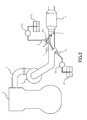
Fig. 2 is a view showing a flight path of a flame generated by a fuel addition valve and a glow plug. -
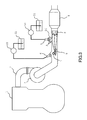
Fig. 3 is a view showing another construction example of the exhaust gas purification apparatus for an internal combustion engine in the first embodiment of the present invention. -
Fig. 4 is a view showing the schematic construction of an exhaust system of an internal combustion engine in a second embodiment of the present invention. -
Fig. 5 is a view showing a flight path of a flame generated by a fuel addition valve and a glow plug. - Hereinafter, specific embodiments of the present invention will be described based on the attached drawings. However, the dimensions, materials, shapes, relative arrangements and so on of component parts described in the embodiments are not intended to limit the technical scope of the present invention to these alone in particular as long as there are no specific statements.
- First, reference will be made to a first embodiment of the present invention based on
Fig. 1 through Fig. 3 .Fig. 1 is a view showing the schematic construction of an exhaust system of an internal combustion engine to which the present invention is applied. Aninternal combustion engine 1 shown inFig. 1 is an internal combustion engine of compression ignition type (diesel engine), but may be an internal combustion engine of spark ignition type (gasoline engine) which is able to carry out a lean combustion operation (lean burn operation). - In
Fig. 1 , anexhaust passage 2 is connected to theinternal combustion engine 1. Theexhaust passage 2 is a passage for circulating or passing a burned gas (an exhaust gas) discharged from the interior of each cylinder of theinternal combustion engine 1. Aturbine 3 of a centrifugal supercharger (turbocharger) is arranged in the middle of theexhaust passage 2. Acatalyst casing 4 is disposed in theexhaust passage 2 at the downstream side of theturbine 3. - The
catalyst casing 4 receives therein a catalyst carrier by which a selective reduction type catalyst is supported in a cylindrical casing. The catalyst carrier is formed by coating an alumina-based or zeolite-based active component (carrier) to a substrate of monolith type which has a honeycomb-shaped cross section made of heat resisting steel such as, for example, cordierite, Fe-Cr-Al steel, etc. Moreover, a precious metal catalyst (e.g., platinum (Pt)) having oxidation ability is supported by the catalyst carrier. - A reducing
agent addition valve 5, a temperature raising device and amixer 8 are mounted on a portion of theexhaust passage 2 which is located between theturbine 3 and thecatalyst casing 4. - The reducing
agent addition valve 5 is disposed in theexhaust passage 2 at the upstream side of thecatalyst casing 4, in a portion (depressed portion) 20 of theexhaust passage 2 which is depressed to a radially outer side thereof, in such a manner that the reducingagent addition valve 5 is not exposed or protruded into theexhaust passage 2. In addition, the reducingagent addition valve 5 is connected to a reducingagent tank 51 through afirst pump 50. Thefirst pump 50 draws the reducing agent stored in the reducingagent tank 51, and at the same time, pressure feeds the reducing agent thus drawn to the reducingagent addition valve 5. The reducingagent addition valve 5 injects the reducing agent pressure fed from thefirst pump 50 into theexhaust passage 2. The reducingagent addition valve 5, thefirst pump 50 and the reducingagent tank 51 are one form of embodiment of a reducing agent supply device according to the present invention. - Here, note that the reducing agent stored in the reducing
agent tank 51 is an ammonia derived reducing agent. As the ammonia derived reducing agent, there can be used a water solution of urea, ammonium carbamate, or the like. In this embodiment, it is assumed that an aqueous urea solution is used as the ammonia derived reducing agent. - The
mixer 8 is a device which is disposed in a portion of theexhaust passage 2 at the downstream side of the reducingagent addition valve 5 and at the upstream side of thecatalyst casing 4, and which serves to promote the reducing agent added from the reducingagent addition valve 5 and the exhaust gas to mix with each other. For example, themixer 8 is constructed in such a manner that the exhaust gas and the reducing agent are agitated by generating a swirl stream of the exhaust gas, or by generating a turbulence in the flow of the exhaust gas. - Here, when the aqueous urea solution is injected from the reducing
agent addition valve 5, the aqueous urea solution flows into themixer 8 together with the exhaust gas. Themixer 8 acts to agitate the aqueous urea solution and the exhaust gas. As a result, the aqueous urea solution and the exhaust gas are mixed with each other in a homogeneous manner, and at the same time, the aqueous urea solution is pyrolyzed or hydrolyzed by receiving the heat of the exhaust gas. When the aqueous urea solution is pyrolyzed or hydrolyzed, ammonia (NH3) is generated. Accordingly, the gas flowing out of themixer 8 becomes a gas in which the exhaust gas and ammonia (NH3) have been mixed in a homogeneous manner. When such a gas flows into thecatalyst casing 4, ammonia (NH3) comes to spread around substantially the whole of thecatalyst casing 4. The ammonia (NH3) having flowed into thecatalyst casing 4 is adsorbed or occluded by the selective reduction type catalyst. The ammonia (NH3) adsorbed or occluded by the selective reduction type catalyst reacts with the nitrogen oxides (NOX) contained in the exhaust gas to generate nitrogen (N2) and water (H2O). That is, the ammonia (NH3) functions as a reducing agent for the nitrogen oxides (NOX). At that time, in cases where the ammonia (NH3) has been adsorbed in a wide range of the selective reduction type catalyst, it is possible to enhance the purification or reduction rate of the nitrogen oxides (NOX) in the selective reduction type catalyst. - The temperature raising device is a device which acts to blow a flame onto those parts (i.e., a wall surface of the
exhaust passage 2 or the mixer 8) which solid matter derived from the reducing agent added from the reducingagent addition valve 5 tends to adhere to or deposit on, thereby rapidly raising the temperature of the parts. The temperature raising device is provided with afuel addition valve 6 and aglow plug 7. - The
fuel addition valve 6 is disposed in a portion of theexhaust passage 2 at the upstream side of the reducingagent addition valve 5. Thefuel addition valve 6 is connected to afuel tank 61 through asecond pump 60. Thefuel tank 61 is a tank which serves to store fuel for theinternal combustion engine 1. Thesecond pump 60 draws the fuel stored in thefuel tank 61, and at the same time, pressure feeds the fuel thus drawn to thefuel addition valve 6. Thefuel addition valve 6 injects the fuel sent from thesecond pump 60 into the exhaust gas in theexhaust passage 2. - The
glow plug 7 is disposed in such a manner that a heat generation portion of theglow plug 7 is located in the vicinity of a nozzle hole of thefuel addition valve 6, or on the flight path of the fuel injected from thefuel addition valve 6. Theglow plug 7 is to cause the heat generation portion to generate heat by converting the electrical energy supplied from an unillustrated battery or alternator into thermal or heat energy. Theglow plug 7 acts to ignite or fire fuel by causing the heat generation portion to generate heat at the time when the fuel is injected from thefuel addition valve 6. - Here, when the reducing agent (aqueous urea solution) injected from the reducing
agent addition valve 5 collides with themixer 8, the wall surface of theexhaust passage 2, etc., solid matter is precipitated in those parts. When such solid matter is exposed to an atmosphere of about 200 to 400 degrees C (denaturation or modification atmosphere), it will turn into difficultly melting substances such as cyanuric acid, melanin, and so on. For that reason, there has been a fear that when the solid matter is intended to be melted and removed by raising the temperature of the exhaust gas or by being heated by means of a heater, the solid matter is exposed to a denaturation atmosphere in the temperature raising process or the heating process, thereby promoting generation of cyanuric acid, melanin, etc. - On the other hand, when the temperature raising device blows a flame to the above-mentioned parts, the solid matter will be exposed to an atmosphere which is sufficiently higher in temperature than the denaturation atmosphere. Moreover, the temperature of the atmosphere to which the solid matter is exposed does not gradually rise through the denaturation atmosphere, but instead goes up at a stretch to a temperature which is higher than that of the denaturation atmosphere. As a result, the solid matter is melted and removed, without being denatured or modified to cyanuric acid, melanin, etc.
- Accordingly, if the amount of fuel added by the
fuel addition valve 6 and the amount of heat generated by theglow plug 7, which together constitute the temperature raising device, are controlled so as to cause a proper amount of flame to arrive at the above-mentioned parts, the parts will receive the heat of the flame thereby to rapidly rise in temperature, so that the solid matter will be melted and removed. Here, note that in the example shown inFig. 1 , the solid matter derived from the reducing agent is easy to adhere to or deposit on themixer 8 and a branching portion (a part indicated by an arrow A inFig. 1 ) between theexhaust passage 2 and thedepressed portion 20. Accordingly, in order to melt and remove the solid matter adhered to or deposited on the branching portion A and themixer 8 in a more reliable manner, the temperature raising device and themixer 8 may be arranged in such a manner that a flame (which is indicated by arrows of broken lines inFig. 2 ) generated by thefuel addition valve 6 and theglow plug 7 arrives to themixer 8 by way of the branching portion A, as shown inFig. 2 . - Specifically, the
fuel addition valve 6 may be composed of an injector of low diffusion type with which the fuel added thereby does not diffuse easily, and may be arranged in such a manner that the nozzle hole of the injector is directed to the branching portion A, and at the same time, the direction thereof is inclined with respect to an axis of theexhaust passage 2. At that time, theglow plug 7 should just be arranged on the flight path of the fuel added from thefuel addition valve 6. According to such arrangements, the fuel injected from thefuel addition valve 6 is reflected on the wall surface of theexhaust passage 2 in the vicinity of the branching portion A, so that it comes to arrive to themixer 8. According to this, the flame generated by theglow plug 7 comes to be blown to themixer 8 by way of the branching portion A. - Accordingly, the solid matter derived from the reducing agent adhered to or deposited on the wall surface of the
exhaust passage 2 and/or themixer 8 can be removed, without being turned into substances which are difficult to melt. Here, note that the temperature raising device can blow a flame onto the branching portion A and themixer 8 in a local manner, so that the temperatures of the branching portion A and themixer 8 can be caused to rise rapidly, while suppressing an increase in the fuel consumption. In addition, because thefuel addition valve 6 and theglow plug 7 can be caused to operate without regard to the operating state of theinternal combustion engine 1, it becomes possible to remove the solid matter derived from the reducing agent, before the amount of adhesion or the amount of deposit thereof becomes excessively large, or it also becomes possible to prohibit the operations of thefuel addition valve 6 and theglow plug 7 when the amount of adhesion or the amount of deposit of the solid matter derived from the reducing agent is exceptionally small. Moreover, when the temperature raising device blows a flame to themixer 8, the temperature of themixer 8 and the ambient temperature inside themixer 8 are made higher. For that reason, evaporation of the aqueous urea solution flowing into themixer 8 is promoted, and at the same time, thermal decomposition and hydrolysis of urea therein are also promoted. As a result, it is possible to suppress a situation in which the aqueous urea solution flows into thecatalyst casing 4 as it is in a liquid phase, and at the same time, it also becomes possible to make the ammonia (NH3) and the exhaust gas much more uniform. - Incidentally, when the flame generated by the temperature raising device strikes against the reducing
agent addition valve 5, there may be caused adverse or harmful effects such as thermal deterioration of the reducingagent addition valve 5, etc. However, because the reducingagent addition valve 5 of this embodiment is arranged in thedepressed portion 20 of theexhaust passage 2 which is depressed or recessed to the radially outer side of theexhaust passage 2, it is possible to avoid the situation where the flame strikes against the reducingagent addition valve 5. Accordingly, the solid matter derived from the reducing agent can be removed, without accompanying the thermal deterioration of the reducingagent addition valve 5, etc. Here, note that as another construction which serves not to expose the reducingagent addition valve 5 to the flame, there can also be adopted one in which a shield plate or the like is disposed at the immediately upstream side of the reducingagent addition valve 5. - In addition, the temperature raising device may be provided with a
distribution plate 9 which is disposed on the flight path of the fuel added from thefuel addition valve 6, as shown inFig. 3 . It is preferable that thedistribution plate 9 be constructed in such a manner that the fuel or flame having collided with thedistribution plate 9 goes to a downstream side, while diffusing in a radial direction within theexhaust passage 2. According to such a construction, it is possible to cause the flame to arrive to the branching portion A, and at the same time, it is also possible to cause the flame to arrive at substantially the entire region of an upstream side end face of themixer 8. As a result, the solid matter derived from the reducing agent being adhered to or deposited on themixer 8 can be removed in a more reliable manner, and at the same time, the evaporation of the aqueous urea solution in themixer 8 as well as the thermal decomposition and hydrolysis of urea can be promoted further more. - Next, reference will be made to a second embodiment of the present invention based on
Fig. 4 andFig. 5 . Here, a construction different from that of the above-mentioned first embodiment will be described, and an explanation of the same construction will be omitted. - The difference between the above-mentioned first embodiment and this second embodiment resides in the feature that the solid matter derived from the reducing agent is removed by using a temperature raising device for raising the temperature of the catalyst.
-
Fig. 4 is a view showing the schematic construction of an exhaust system of aninternal combustion engine 1 according to this second embodiment of the present invention. InFig. 4 , the same symbols are attached to the same components as those in the above-mentioned first embodiment. InFig. 4 , aparticulate filter 10 having an oxidation catalyst supported thereon is disposed in a portion of anexhaust passage 2 at the downstream side of afuel addition valve 6 and aglow plug 7, and at the upstream side of a reducingagent addition valve 5. Theparticulate filter 10 is formed in a cylindrical shape having an outside diameter smaller than an inside diameter of theexhaust passage 2, and is arranged in coaxial relation with theexhaust passage 2. Here, note that in place of theparticulate filter 10, a catalyst carrier of a cylindrical shape may be arranged, and an oxidation catalyst may be supported by the catalyst carrier. - In addition, the reducing
agent addition valve 5 of this embodiment is disposed in a straight portion of theexhaust passage 2, in adepressed portion 21 of theexhaust passage 2 which is depressed to a radially outer side thereof, in such a manner that the reducingagent addition valve 5 is not exposed or protruded into theexhaust passage 2. On the other hand, thefuel addition valve 6 of the temperature raising device is disposed in the straight portion of theexhaust passage 2, in adepressed portion 22 of theexhaust passage 2 which is depressed to a radially outer side thereof, in such a manner that thefuel addition valve 6 is not exposed or protruded into theexhaust passage 2. Theglow plug 7 of the temperature raising device is disposed in such a manner that a heat generation portion of theglow plug 7 is located in the vicinity of a nozzle hole of thefuel addition valve 6, or on the flight path of the fuel injected from thefuel addition valve 6, similarly to the above-mentioned first embodiment. - In the exhaust gas purification apparatus for an internal combustion engine as constructed in this manner, in cases where particulate matter trapped by the
particulate filter 10 is to be oxidized, or in cases where the catalyst supported on theparticulate filter 10 is to be activated, etc., when thefuel addition valve 6 and theglow plug 7 are caused to operate, a flame generated by thefuel addition valve 6 and theglow plug 7 will arrive at the vicinity of theparticulate filter 10 by receiving the pressure of the exhaust gas. In that case, the temperature of theparticulate filter 10 and the temperature of the exhaust gas flowing into theparticulate filter 10 will go up quickly. As a result, the particulate matter trapped by theparticulate filter 10 will be oxidized, or the oxidation catalyst supported on theparticulate filter 10 will be activated quickly. - However, when the reducing agent injected from the reducing
agent addition valve 5 collides with the wall surface of theexhaust passage 2, solid matter derived from the reducing agent is precipitated on the wall surface. In the example shown inFig. 4 , the solid matter derived from the reducing agent is easy to adhere to or deposit on a stepped portion (a part indicated by an arrow B inFig. 4 ) in a boundary between thedepressed portion 21 and theexhaust passage 2. - Accordingly, the temperature raising device of this embodiment is provided with a
distribution plate 11 which serves to distribute the flame generated by thefuel addition valve 6 and theglow plug 7 to theparticulate filter 10, the stepped portion B and themixer 8. Thedistribution plate 11 is disposed at a location downstream of the heat generation portion of theglow plug 7 on the flight path of the fuel injected from thefuel addition valve 6. At that time, thedistribution plate 11 should be disposed in such a manner that the fuel or the flame having collided with thedistribution plate 11 can arrive to themixer 8 while passing through a gap between theparticulate filter 10 and theexhaust passage 2. - For example, in the example shown in
Fig. 4 , the fuel added from thefuel addition valve 6 flies to the radially inner side of theexhaust passage 2, and hence, thedistribution plate 11 is disposed substantially in parallel with an axial direction of theexhaust passage 2. Thus, when thedistribution plate 11 is arranged in this manner, as shown inFig. 5 , the flame (flame indicated by an arrow of a broken line inFig. 5 ) generated by thefuel addition valve 6 and theglow plug 7 collides with thedistribution plate 11, and thereafter is dispersed in a radial direction of theexhaust passage 2. - A portion of the flame dispersed to the vicinity of the periphery of the
exhaust passage 2 flows into the gap between theparticulate filter 10 and theexhaust passage 2. In addition, a portion of the flame dispersed to the vicinity of the center of theexhaust passage 2 collides with an upstream side end face of theparticulate filter 10, and thereafter flows into the gap between theparticulate filter 10 and theexhaust passage 2. The flame having flowed into the gap between theparticulate filter 10 and theexhaust passage 2 goes in the axial direction of theexhaust passage 2. Subsequently, when the flame arrives downstream of a downstream side end face of theparticulate filter 10, a part of the flame advances along a peripheral edge portion of theexhaust passage 2 in the axial direction thereof, and the remaining flame advances to a downstream side of theexhaust passage 2, while diffusing to a radially inner side of theexhaust passage 2. In other words, the flame will arrive at themixer 8, while spreading in the radial direction in the downstream of the downstream side end face of theparticulate filter 10. - Accordingly, the flame generated by the
fuel addition valve 6 and theglow plug 7 will be distributed to theparticulate filter 10, the stepped portion B and themixer 8. As a result, the solid matter adhered to or deposited on the stepped portion B and/or themixer 8 is removed, without denaturing to difficultly melting substances such as cyanuric acid, melanin, and so on. - In addition, when the flame collides with the upstream side end face of the
particulate filter 10, or when the flame passes through the gap between theparticulate filter 10 and theexhaust passage 2, the heat of the flame is conducted to an outer peripheral surface of theparticulate filter 10, so it also becomes possible to cause the temperature of theparticulate filter 10 to go up quickly. - Moreover, in the downstream of the downstream side end face of the
particulate filter 10, the flame arrives at themixer 8 while spreading in the radial direction, so that it can be caused to arrive at substantially the entire region of the upstream side end face of themixer 8. As a result, the solid matter derived from the reducing agent being adhered to or deposited on themixer 8 can be removed in a more reliable manner, and at the same time, the evaporation of the aqueous urea solution in themixer 8 as well as the thermal decomposition and hydrolysis of urea can be promoted further more. - According to the second embodiment described above, a temperature raising device for raising the temperature of the
particulate filter 10 and a temperature raising device for removing solid matter derived from a reducing agent can be shared. As a result, it becomes possible to remove the solid matter derived from the reducing agent in a suitable manner, while suppressing an increase in the number of component parts. -
- 1 internal combustion engine
- 2 exhaust passage
- 3 turbine
- 4 catalyst casing
- 5 reducing agent addition valve
- 6 fuel addition valve
- 7 glow plug
- 8 mixer (mixing device)
- 9 distribution plate
- 10 particulate filter
- 11 distribution plate
- 50 first pump
- 51 reducing agent tank
- 60 second pump
- 61 fuel tank
Claims (4)
- An exhaust gas purification apparatus of an internal combustion engine comprising:a selective reduction type catalyst disposed in an exhaust passage of the internal combustion engine;a reducing agent supply device to supply an ammonia derived reducing agent into a portion of the exhaust passage at the upstream side of said selective reduction type catalyst;a mixing device disposed in a portion of the exhaust passage at the upstream side of said selective reduction type catalyst and at the downstream side of said reducing agent supply device so as to promote the reducing agent to be supplied from said reducing agent supply device and an exhaust gas to mix with each other; anda temperature raising device disposed in a portion of the exhaust passage at the upstream side of said mixing device so as to raise the temperature of said mixing device by blowing a flame to said mixing device.
- The exhaust gas purification apparatus for an internal combustion engine according to claim 1, wherein said temperature raising device is disposed in a portion of the exhaust passage at the upstream side of said reducing agent supply device so as to blow the flame to a place of collision at which the reducing agent to be supplied from said reducing agent supply device collides with a wall surface of the exhaust passage, as well as to said mixing device.
- The exhaust gas purification apparatus for an internal combustion engine according to claim 2, wherein said reducing agent supply device is disposed at a position at which the flame generated by said temperature raising device does not arrive.
- The exhaust gas purification apparatus for an internal combustion engine according to claim 2 or 3, wherein said temperature raising device is provided with a distribution plate that serves to distribute the flame to said place of collision and said mixing device.
Applications Claiming Priority (1)
| Application Number | Priority Date | Filing Date | Title |
|---|---|---|---|
| PCT/JP2011/060466 WO2012147205A1 (en) | 2011-04-28 | 2011-04-28 | Exhaust gas purifier for internal combustion engine |
Publications (2)
| Publication Number | Publication Date |
|---|---|
| EP2703612A1 true EP2703612A1 (en) | 2014-03-05 |
| EP2703612A4 EP2703612A4 (en) | 2014-11-19 |
Family
ID=47071745
Family Applications (1)
| Application Number | Title | Priority Date | Filing Date |
|---|---|---|---|
| EP11864274.3A Withdrawn EP2703612A4 (en) | 2011-04-28 | 2011-04-28 | EXHAUST GAS PURIFIER FOR AN INTERNAL COMBUSTION ENGINE |
Country Status (4)
| Country | Link |
|---|---|
| EP (1) | EP2703612A4 (en) |
| JP (1) | JP5664771B2 (en) |
| CN (1) | CN103502591B (en) |
| WO (1) | WO2012147205A1 (en) |
Cited By (4)
| Publication number | Priority date | Publication date | Assignee | Title |
|---|---|---|---|---|
| US20160032801A1 (en) * | 2014-07-31 | 2016-02-04 | Caterpillar Inc. | Aftertreatment system having multiple dosing circuits |
| WO2018087263A1 (en) * | 2016-11-11 | 2018-05-17 | Perkins Engines Company Limited | Diesel exhaust fluid injector |
| DE102017217001A1 (en) * | 2017-09-26 | 2019-03-28 | Bayerische Motoren Werke Aktiengesellschaft | Exhaust system for an internal combustion engine |
| FR3072123A1 (en) * | 2017-10-05 | 2019-04-12 | Psa Automobiles Sa | MIXING BOX AND EXHAUST GAS POST-PROCESSING DEVICE INCORPORATING IT |
Families Citing this family (4)
| Publication number | Priority date | Publication date | Assignee | Title |
|---|---|---|---|---|
| KR101699614B1 (en) * | 2015-06-01 | 2017-01-24 | 두산엔진주식회사 | Burner system |
| JP2020084930A (en) * | 2018-11-29 | 2020-06-04 | いすゞ自動車株式会社 | Exhaust emission control device and vehicle |
| CN112393273B (en) * | 2020-12-04 | 2024-11-15 | 重庆超力高科技股份有限公司 | Premix burner |
| WO2025080740A1 (en) * | 2023-10-10 | 2025-04-17 | Donaldson Company, Inc. | Exhaust aftertreatment system |
Family Cites Families (13)
| Publication number | Priority date | Publication date | Assignee | Title |
|---|---|---|---|---|
| JP3892452B2 (en) | 2004-07-16 | 2007-03-14 | 日産ディーゼル工業株式会社 | Engine exhaust purification system |
| JP2006112401A (en) | 2004-10-18 | 2006-04-27 | Denso Corp | Catalyst temperature riser |
| US7874147B2 (en) * | 2007-04-26 | 2011-01-25 | Emcon Technologies Llc | Method and apparatus for a non-catalytic NOx reduction |
| JP4827256B2 (en) | 2007-06-21 | 2011-11-30 | 日野自動車株式会社 | Exhaust treatment device |
| JP5000405B2 (en) * | 2007-07-06 | 2012-08-15 | 日野自動車株式会社 | Exhaust purification device |
| DE102008040569A1 (en) * | 2008-07-21 | 2010-01-28 | Robert Bosch Gmbh | Exhaust gas system i.e. DENOX system, for reducing nitrogen oxide in exhaust gas of diesel engine, has field generating device generating electrical and/or magnetic field for flat crystal growth of reducing agent crystals |
| US8511075B2 (en) * | 2008-09-19 | 2013-08-20 | Caterpillar Inc. | Flame deflector for emissions control system |
| JP2010096005A (en) * | 2008-10-14 | 2010-04-30 | Bosch Corp | Exhaust emission control device for internal combustion engine |
| US20100269492A1 (en) * | 2009-04-27 | 2010-10-28 | Tenneco Automotive Operating Company Inc. | Diesel aftertreatment system |
| JP5316266B2 (en) * | 2009-07-03 | 2013-10-16 | いすゞ自動車株式会社 | Reducing agent supply device for urea SCR catalyst |
| US8887495B2 (en) * | 2009-07-14 | 2014-11-18 | GM Global Technology Operations LLC | Ash filter, exhaust gas treatment system incorporating the same and method of using the same |
| JP5500909B2 (en) * | 2009-08-25 | 2014-05-21 | ボッシュ株式会社 | Exhaust purification device |
| JP2011064069A (en) * | 2009-09-15 | 2011-03-31 | Toyota Industries Corp | Exhaust gas treatment system |
-
2011
- 2011-04-28 WO PCT/JP2011/060466 patent/WO2012147205A1/en not_active Ceased
- 2011-04-28 EP EP11864274.3A patent/EP2703612A4/en not_active Withdrawn
- 2011-04-28 CN CN201180070484.1A patent/CN103502591B/en not_active Expired - Fee Related
- 2011-04-28 JP JP2013511857A patent/JP5664771B2/en not_active Expired - Fee Related
Cited By (4)
| Publication number | Priority date | Publication date | Assignee | Title |
|---|---|---|---|---|
| US20160032801A1 (en) * | 2014-07-31 | 2016-02-04 | Caterpillar Inc. | Aftertreatment system having multiple dosing circuits |
| WO2018087263A1 (en) * | 2016-11-11 | 2018-05-17 | Perkins Engines Company Limited | Diesel exhaust fluid injector |
| DE102017217001A1 (en) * | 2017-09-26 | 2019-03-28 | Bayerische Motoren Werke Aktiengesellschaft | Exhaust system for an internal combustion engine |
| FR3072123A1 (en) * | 2017-10-05 | 2019-04-12 | Psa Automobiles Sa | MIXING BOX AND EXHAUST GAS POST-PROCESSING DEVICE INCORPORATING IT |
Also Published As
| Publication number | Publication date |
|---|---|
| WO2012147205A1 (en) | 2012-11-01 |
| EP2703612A4 (en) | 2014-11-19 |
| JP5664771B2 (en) | 2015-02-04 |
| CN103502591B (en) | 2016-02-17 |
| JPWO2012147205A1 (en) | 2014-07-28 |
| CN103502591A (en) | 2014-01-08 |
Similar Documents
| Publication | Publication Date | Title |
|---|---|---|
| EP2703612A1 (en) | Exhaust gas purifier for internal combustion engine | |
| CN101389834B (en) | Exhaust aftertreatment device with star-plugged turbulator | |
| US9057312B2 (en) | System and apparatus for reducing reductant deposit formation in exhaust aftertreatment systems | |
| US8752365B2 (en) | Method for dosing an urea based reducing agent into a gas exhaust stream | |
| US20120204541A1 (en) | Exhaust mixer element and method for mixing | |
| EP1481719A2 (en) | Engine exhaust gas treatment system and exhaust gas treatment process | |
| US20200102873A1 (en) | Diesel emissions fluid injector mixer | |
| JP5937517B2 (en) | Dosing module that administers urea-based reducing agent to the exhaust gas stream | |
| EP2693012B1 (en) | Exhaust gas purification apparatus for internal combustion engine | |
| JP2009002213A (en) | Exhaust treatment device | |
| JP2008240722A (en) | Exhaust emission control device | |
| US9421496B2 (en) | Exhaust gas purification apparatus for internal combustion engine | |
| US20150361842A1 (en) | Exhaust system for a vehicle | |
| US20190388851A1 (en) | Large engine mixer for exhaust system | |
| US20160281563A1 (en) | Exhaust system for an internal combustion engine of a motor vehicle and method for operating an exhaust system | |
| WO2013017943A1 (en) | Exhaust gas purification system and exhaust gas purification method for internal combustion engine | |
| US20170218821A1 (en) | Apparatus for producing ammonia | |
| CN112096489A (en) | Exhaust gas system for exhaust gas aftertreatment |
Legal Events
| Date | Code | Title | Description |
|---|---|---|---|
| PUAI | Public reference made under article 153(3) epc to a published international application that has entered the european phase |
Free format text: ORIGINAL CODE: 0009012 |
|
| 17P | Request for examination filed |
Effective date: 20131107 |
|
| AK | Designated contracting states |
Kind code of ref document: A1 Designated state(s): AL AT BE BG CH CY CZ DE DK EE ES FI FR GB GR HR HU IE IS IT LI LT LU LV MC MK MT NL NO PL PT RO RS SE SI SK SM TR |
|
| DAX | Request for extension of the european patent (deleted) | ||
| A4 | Supplementary search report drawn up and despatched |
Effective date: 20141022 |
|
| RIC1 | Information provided on ipc code assigned before grant |
Ipc: F01N 3/28 20060101ALI20141016BHEP Ipc: F01N 3/20 20060101ALI20141016BHEP Ipc: F01N 3/36 20060101ALI20141016BHEP Ipc: F01N 3/38 20060101ALI20141016BHEP Ipc: F01N 3/08 20060101AFI20141016BHEP Ipc: F01N 3/025 20060101ALI20141016BHEP |
|
| 17Q | First examination report despatched |
Effective date: 20160811 |
|
| STAA | Information on the status of an ep patent application or granted ep patent |
Free format text: STATUS: EXAMINATION IS IN PROGRESS |
|
| STAA | Information on the status of an ep patent application or granted ep patent |
Free format text: STATUS: THE APPLICATION IS DEEMED TO BE WITHDRAWN |
|
| 18D | Application deemed to be withdrawn |
Effective date: 20180801 |