EP2703545A2 - Washing machine having detergent supply device - Google Patents
Washing machine having detergent supply device Download PDFInfo
- Publication number
- EP2703545A2 EP2703545A2 EP13181733.0A EP13181733A EP2703545A2 EP 2703545 A2 EP2703545 A2 EP 2703545A2 EP 13181733 A EP13181733 A EP 13181733A EP 2703545 A2 EP2703545 A2 EP 2703545A2
- Authority
- EP
- European Patent Office
- Prior art keywords
- water supply
- passage
- water
- frame
- detergent
- Prior art date
- Legal status (The legal status is an assumption and is not a legal conclusion. Google has not performed a legal analysis and makes no representation as to the accuracy of the status listed.)
- Granted
Links
- 239000003599 detergent Substances 0.000 title claims abstract description 106
- 238000005406 washing Methods 0.000 title claims abstract description 22
- XLYOFNOQVPJJNP-UHFFFAOYSA-N water Substances O XLYOFNOQVPJJNP-UHFFFAOYSA-N 0.000 claims abstract description 349
- 230000008878 coupling Effects 0.000 claims abstract description 24
- 238000010168 coupling process Methods 0.000 claims abstract description 24
- 238000005859 coupling reaction Methods 0.000 claims abstract description 24
- 230000002093 peripheral effect Effects 0.000 claims abstract description 19
- 230000002708 enhancing effect Effects 0.000 abstract description 2
- 238000003860 storage Methods 0.000 description 18
- 239000002979 fabric softener Substances 0.000 description 15
- 239000007788 liquid Substances 0.000 description 11
- 239000013042 solid detergent Substances 0.000 description 8
- 239000008400 supply water Substances 0.000 description 7
- 238000004519 manufacturing process Methods 0.000 description 3
- 238000005192 partition Methods 0.000 description 3
- 230000003247 decreasing effect Effects 0.000 description 2
- 238000000034 method Methods 0.000 description 2
- 229910000838 Al alloy Inorganic materials 0.000 description 1
- 238000001746 injection moulding Methods 0.000 description 1
- 238000003756 stirring Methods 0.000 description 1
- 238000003466 welding Methods 0.000 description 1
Images


Classifications
-
- D—TEXTILES; PAPER
- D06—TREATMENT OF TEXTILES OR THE LIKE; LAUNDERING; FLEXIBLE MATERIALS NOT OTHERWISE PROVIDED FOR
- D06F—LAUNDERING, DRYING, IRONING, PRESSING OR FOLDING TEXTILE ARTICLES
- D06F39/00—Details of washing machines not specific to a single type of machines covered by groups D06F9/00 - D06F27/00
- D06F39/02—Devices for adding soap or other washing agents
- D06F39/028—Arrangements for selectively supplying water to detergent compartments
-
- D—TEXTILES; PAPER
- D06—TREATMENT OF TEXTILES OR THE LIKE; LAUNDERING; FLEXIBLE MATERIALS NOT OTHERWISE PROVIDED FOR
- D06F—LAUNDERING, DRYING, IRONING, PRESSING OR FOLDING TEXTILE ARTICLES
- D06F39/00—Details of washing machines not specific to a single type of machines covered by groups D06F9/00 - D06F27/00
- D06F39/08—Liquid supply or discharge arrangements
- D06F39/081—Safety arrangements for preventing water damage
-
- D—TEXTILES; PAPER
- D06—TREATMENT OF TEXTILES OR THE LIKE; LAUNDERING; FLEXIBLE MATERIALS NOT OTHERWISE PROVIDED FOR
- D06F—LAUNDERING, DRYING, IRONING, PRESSING OR FOLDING TEXTILE ARTICLES
- D06F39/00—Details of washing machines not specific to a single type of machines covered by groups D06F9/00 - D06F27/00
- D06F39/08—Liquid supply or discharge arrangements
- D06F39/088—Liquid supply arrangements
-
- D—TEXTILES; PAPER
- D06—TREATMENT OF TEXTILES OR THE LIKE; LAUNDERING; FLEXIBLE MATERIALS NOT OTHERWISE PROVIDED FOR
- D06F—LAUNDERING, DRYING, IRONING, PRESSING OR FOLDING TEXTILE ARTICLES
- D06F39/00—Details of washing machines not specific to a single type of machines covered by groups D06F9/00 - D06F27/00
- D06F39/12—Casings; Tubs
-
- D—TEXTILES; PAPER
- D06—TREATMENT OF TEXTILES OR THE LIKE; LAUNDERING; FLEXIBLE MATERIALS NOT OTHERWISE PROVIDED FOR
- D06F—LAUNDERING, DRYING, IRONING, PRESSING OR FOLDING TEXTILE ARTICLES
- D06F39/00—Details of washing machines not specific to a single type of machines covered by groups D06F9/00 - D06F27/00
- D06F39/02—Devices for adding soap or other washing agents
- D06F39/024—Devices for adding soap or other washing agents mounted on the agitator or the rotating drum; Free body dispensers
Definitions
- the following description relates to a washing machine having a detergent supply device to supply a detergent to the inside of the washing machine.
- a washing machine is an appliance that washes laundry using electric power.
- a washing machine comprises a tub to store wash water, a drum rotatably mounted in the tub, a pulsator rotatably mounted on a bottom of the drum, and a motor to rotate the drum and the pulsator.
- the drum and the pulsator are rotated by the motor, and the pulsator stirs the laundry placed in the drum together with the wash water to remove dirt from the laundry.
- a detergent supply device of a drum washing machine includes a detergent storage unit to store at least one of a solid detergent and a liquid detergent, and a water supply unit to supply water to the detergent storage unit.
- the water supply unit includes an upper frame and a lower frame that may be thermal welded to each other to prevent water leakage.
- the upper frame and the lower frame of the water supply unit may not be perfectly thermal welded, water leakage through an imperfectly welded portion may occur when a pressure of water supplied from an external water source is relatively high. Due to the water leakage, water to be supplied to only a solid detergent may be undesirably supplied to a liquid detergent or a fabric softener. Therefore, a user may not obtain desired washing result.
- a thermal welding process with respect to the upper and lower frames may increase manufacturing costs.
- a detergent supply device of a washing machine includes a housing having an opening, a detergent case to store a detergent, the detergent case being movably coupled to the housing through the opening, a water supply frame coupled to an upper portion of the housing to guide water to the detergent case, and a cover frame to sealingly cover an upper portion of the water supply frame, wherein the water supply frame includes a first passage rib to define a first water supply passage, a second passage rib to define a second water supply passage which communicates with the first water supply passage and guides water in a direction different from the first water supply passage, and at least one guide rib connecting the first passage rib and the second passage rib to enable water passing through the first water supply passage to flow toward the second water supply passage.
- the water supply frame may further include at least one drain slot communicating with the first water supply passage and the second water supply passage and formed above the guide rib.
- the guide rib may guide water passing through the first water supply passage toward the second water supply passage, and if the level of water in the water supply frame is higher than the height of the guide rib, the guide rib may guide at least a part of water in the water supply frame toward the drain slot.
- the guide rib may have a lower height than the first passage rib and the second passage rib.
- the drain slot may be defined by the guide rib, the first passage rib and the second passage rib.
- the water supply frame may further include at least one third passage rib disposed between the first passage rib and the second passage rib, and the third passage rib may include a first surface to define the first water supply passage with the first passage rib, and a second surface to define the second water supply passage with the second passage rib, the second surface being opposite to the first surface.
- the cover frame may include a plurality of coupling protrusions protruding from an inner peripheral surface thereof to support a bottom surface of the water supply frame.
- a washing machine includes a main body, a drum rotatably mounted in the main body, and a detergent supply device disposed at an upper portion of the main body to supply a detergent into the drum, wherein the detergent supply device includes a housing, a detergent case to store a detergent, the detergent case being movably coupled to the housing, a water supply frame coupled to an upper portion of the housing to guide water to the detergent case, and a cover frame to sealingly cover an upper portion of the water supply frame, the cover frame including a plurality of coupling protrusions protruding from an inner peripheral surface thereof to support a bottom surface of the water supply frame.
- the plurality of coupling protrusions may be arranged apart from each other along the inner peripheral surface of the cover frame.
- Each of the coupling protrusions may include a contact surface configured to be in contact with the bottom surface of the water supply frame when the water supply frame and the cover frame are in a coupled state, and a slanted surface connecting the contact surface and the inner peripheral surface of the cover frame, the slanted surface being slanted downwardly from the contact surface to the inner peripheral surface of the cover frame.
- the water supply frame may include a plurality of gap forming protrusions protruding from an outer bottom surface thereof and arranged corresponding to positions of the coupling protrusions so that a gap is formed between each of the gap forming protrusions and each of the coupling protrusions.
- the cover frame may further include a plurality of locking hooks to fix the cover frame coupled with the water supply frame to the housing, and the plurality of locking hooks may be arranged along an outer peripheral surface of the cover frame.
- the water supply frame may include a water supply passage through which water supplied from an external water source moves, a plurality of through-holes formed through the bottom surface of the water supply frame, through which water moving along the water supply passage drops into the detergent case, and at least one guide rib provided in the water supply passage and configured to enable water introduced into a portion of the water supply passage to change a moving direction and move toward another portion of the water supply passage.
- the water supply passage may include at least one first water supply passage into which water supplied from an external water source is introduced, at least one second water supply passage configured to communicate with the first water supply passage and change a moving direction of water having passed through the first water supply passage, and at least one third water supply passages configured to communicate with the second water supply passage and change a moving direction of water having passed through the second water supply passage.
- the guide rib may be disposed at a junctional region between the second water supply passage and the third water supply passage to enable water passing through the second water supply passage to move toward the third water supply passage.
- the third water supply passage may be disposed between the first water supply passage and the second water supply passage.
- the second water supply passage may be provided in at least two parts which are arranged while interposing the first water supply passage therebetween.
- the water supply frame may further include a plurality of passage ribs protruding from an inner bottom surface thereof to define the water supply passage, and the guide rib may have a lower height than the passage ribs.
- the guide rib may have a first end connected to a surface of a first passage rib defining the first water supply passage and the third water supply passage, and a second end connected to a surface of a second passage rib defining the second water supply passage.
- the water supply frame may further include at least one drain slot formed above the guide rib. If a level of water introduced into the water supply passage is higher than the guide rib, the drain slot may allow the water in the water supply passage to be discharged from the water supply frame.
- the water supply frame may further include at least one drain slot defined by the cover frame, the first passage rib, the second passage rib and the guide rib.
- the drain slot may communicate with the second water supply passage and the third water supply passage.
- a washing machine includes a main body, a tub disposed in the main body to store wash water, and a detergent supply device disposed at an upper portion of the main body to supply a detergent into the tub, wherein the detergent supply device includes a lower frame to store a detergent, a middle frame coupled to an upper portion of the lower frame, the middle frame including at least one water supply passage through which water supplied from an external water source moves, and at least one through-hole formed through the water supply passage, through which water moving along the water supply passage drops into the lower frame, and an upper frame including a receiving part to receive the middle frame therein, and a plurality of coupling protrusions protruding from an inner surface of the receiving part to support a bottom surface of the middle frame so that the middle frame is fixed in the receiving part.
- the plurality of coupling protrusions may be arranged apart from each other along an inner peripheral surface of the receiving part.
- the upper frame may further include a plurality of locking hooks to fix the upper frame coupled with the middle frame to the lower frame.
- the middle frame may further include a first water supply part to supply water to a solid detergent stored in the lower frame, and a second water supply part to supply water to a liquid detergent and a fabric softener stored in the lower frame.
- the first water supply part may include at least one first drain slot to prevent water supplied to the first water supply part from moving to the second water supply part in a relatively high water pressure condition.
- the middle frame may further include at least one drain passage provided between the first water supply part and the second water supply part to prevent water escaping from the first water supply part from moving to the second water supply part in a relatively high water pressure condition, and a plurality of second drain slots formed through the drain passage so that water moving along the drain passage is discharged to the lower frame.
- the first water supply part may further include at least one guide rib to prevent water supplied to the first water supply part from being discharged through the first drain slot in a relatively low water pressure condition.
- a part of the water introduced into the first water supply part may be discharged to the outside of the detergent supply device through at least one of the first drain slot and the second drain slots.
- the components of the detergent supply device may be easily assembled by simple engagement methods, manufacturing processes may be simplified, and productivity may be enhanced.
- water supplied to the detergent supply device may be evenly distributed in the detergent supply device and then supplied to the detergent case. Accordingly, the washing machine may maintain superior washing performance, and thus operational reliability is increased.
- FIG. 1 is a view illustrating constitution of a washing machine according to an embodiment of the present disclosure.
- a washing machine 1 comprises a main body 10 defining an external appearance of the washing machine and supporting components mounted inside the main body 10, a tub 20 disposed in the main body 10, a drum 30 rotatably disposed in the tub 20, and a motor 40 to drive the drum 30.
- the main body 10 is formed with a laundry entrance hole 11 at a front portion thereof, through which a user places laundry into the drum 30.
- a door 12 is provided at the front portion of the main body 10 in order to open and close the laundry entrance hole 11.
- Water supply hoses 50 to supply wash water to the tub 20 are installed above the tub 20.
- One end portion of each of the water supply hoses 50 is connected to an external water supply source (not shown), and the other end portion of each of the water supply hoses 50 is connected to a detergent supply device 100.
- the detergent supply device 100 is connected to the tub 20 through a connection pipe 54, and includes a detergent case 120 to store a detergent or a fabric softener. Water supplied through the water supply hoses 50 passes through the detergent case 120 and is mixed with the detergent or the fabric softener, and then the water containing the detergent or the fabric softener is supplied to the inside of the tub 20.
- a drain pump 60 and a drain pipe 62 are mounted under the tub 20, in order to discharge water in the tub 20 to the outside of the main body 10.
- the tub 20 is supported by a damper 80.
- the damper 80 connects an inner bottom surface of the main body 10 and an outer surface of the tub 20.
- the drum 30 includes a cylindrical body 31, a front plate 32 provided at a front portion of the cylindrical body 31, and a rear plate 33 provided at a rear portion of the cylindrical body 31.
- the front plate 32 is formed with an opening 32a through which laundry is placed or removed into/from the drum 30.
- the rear plate 33 is connected with a driving shaft 42 to transmit power from the motor 40 to the drum 30.
- a plurality of through-holes 34 for wash water circulation is formed through a peripheral surface of the drum 30.
- the drum 30 is also provided with a plurality of lifters 35 on an inner circumferential surface thereof, in order to lift laundry when the drum 30 rotates.
- the driving shaft 42 is disposed between the drum 30 and the motor 40. One end portion of the driving shaft 42 is connected to the rear plate 33 of the drum 30, and the other end portion of the driving shaft 42 extends outside a rear wall of the tub 20. If the motor 40 drives the driving shaft 42, the drum 30 connected to the driving shalt 42 rotates about the driving shaft 42.
- a bearing housing 70 is mounted to the rear wall of the tub 20 so as to rotatably support the driving shaft 42.
- the bearing housing 70 may be made of, for example, aluminum alloy, and may be inserted into the rear wall of the tub 20 when the tub 20 is formed by injection molding.
- Bearings 72 are disposed between the bearing housing 70 and the driving shaft 42 so that the driving shaft 42 may effectively rotate.
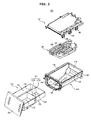
- FIG. 2 is an exploded perspective view of the detergent supply device according to an embodiment of the present disclosure
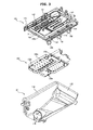
- FIG. 3 is an exploded perspective view of the detergent supply device of FIG. 2 , taken from a different angle
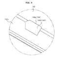
- FIG. 4 is an enlarged view of an A portion in FIG. 3
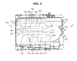
- FIG. 5 is a plan view illustrating engagement of a water supply frame and a cover frame of the detergent supply device according to the embodiment of the present disclosure
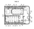
- FIG. 6 is a bottom view illustrating engagement of the water supply frame and the cover frame of the detergent supply device according to the embodiment of the present disclosure
- FIG. 7 is a sectional view taken along line I-I in FIG. 5
- FIG. 8 is an enlarged view of a B portion in FIG. 7
- FIG. 9 is a perspective view illustrating the water supply frame depicted in FIG. 2
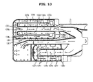
- FIG. 10 is a view illustrating water flow along a water supply passage of the water supply frame depicted in FIG. 2 .
- the detergent case 120 is omitted.
- the detergent supply device 100 includes a housing 110, a detergent case 120 configured to store a detergent or a fabric softener and movably coupled to the housing 110, a water supply frame 130 coupled to an upper portion of the housing 110 in order to supply water to the housing 110, and a cover frame 140 sealingly cover an upper portion of the water supply flame 130.
- the housing 110 includes a housing body 112 in which the detergent case 120 is received, an opening 114 formed at a front portion of the housing body 112, through which the detergent case 120 is withdrawn from the housing body 112, and rails 116 provided at opposite inner lateral surfaces of the housing body 112 in order to support the detergent case 120 so that the detergent case 120 may slide with respect to the housing 110.
- a discharge port 118 is formed at a bottom surface of the housing body 112, through which a detergent or fabric softener mixed with water is discharged from the detergent supply device 100.
- the discharge port 118 is connected to the connection pipe 54.
- the detergent or fabric softener mixed with water discharged through the discharge port 118 is fed to the tub 20 via the connection pipe 54.
- the bottom surface of the housing body 112 is slanted downwardly toward the discharge port 118 so that the detergent or fabric softener mixed with water may not accumulate on the bottom surface of the housing body 112 but may be effectively discharged through the discharge port 118.
- the housing body 112 is provided with a fixing part 119, and the cover frame 140 is provided with locking hooks 146.
- the fixing part 119 protrudes outwardly along an upper periphery of the housing body 112 so that the locking hooks 146 of the cover frame 140 may be hooked to the fixing part 119 when the housing 110 and the cover frame 140 are coupled.
- the detergent case 120 is partitioned into a first storage part 121 to store a solid detergent, a second storage part 122 divided from the first storage part 121 by a first partition wall 124 to store a fabric softener, and a third storage part 123 divided from the first storage part 121 by the first partition wall 124 and divided from the second storage part 122 by a second partition wall 125 to store a liquid detergent.
- a liquid detergent discharge device 127 is provided at the third storage part 123 so as to effectively discharge a liquid detergent from the third storage part 123.
- the liquid detergent discharge device 127 includes a siphon pipe 127a protruding from a bottom surface of the third storage part 123 by a designated length, and a siphon cap 127b coupled to an outer portion of the siphon pipe 127a.
- a handle 128 may be provided in front of the first and second storage parts 121 and 122 to enable a user to put or withdraw the detergent case 120 into/from the housing 110.
- the water supply frame 130 includes a first water supply part 131 disposed above the first storage part 121 of the detergent case 120 to supply water to a solid detergent stored in the first storage part 121, a second water supply part 132 disposed above the second storage part 122 of the detergent case 120 to supply water to a fabric softener stored in the second storage part 122, and a third water supply part 133 disposed above the third storage part 123 of the detergent case 120 to supply water to a liquid detergent stored in the third storage part 123.
- the water supply frame 130 further includes a plurality of water supply passages 134 along which water supplied from an external water source (not shown) to the water supply frame 130 moves, and a plurality of through-holes 130b formed through a bottom surface of the water supply frame 130 so that water moving along the water supply passages 134 may drop into the detergent case 120 through the through-holes 130b.
- the water supply passages 134 include a first water supply passage 134a configured to guide water supplied from an external water source to the water supply frame 130 to the first water supply part 131, second water supply passages 134b configured to communicate with the first water supply passage 134a and change a moving direction of the water having passed through the first water supply passage 134a, and third water supply passages 134c configured to communicate with the second water supply passages 134b and change a moving direction of the water having passed through the second water supply passages 134b.
- the water supply passages 134 include a fourth water supply passage 134d configured to guide water supplied from an external water source to the water supply frame 130 to the second water supply part 132, a fifth water supply passage 134e configured to guide water supplied from an external water source to the water supply frame 130 to the third water supply part 133, and sixth water supply passages 134f configured to communicate with the fifth water supply passage 134e and change a moving direction of the water having passed through the fifth water supply passage 134e.
- the first water supply passage 134a is interposed between a pair of third water supply passages 134c, and each of the third water supply passages 134c is interposed between the first water supply passage 134a and each of a pair of second water supply passages 134b.
- the fifth water supply passage 134e is interposed between a pair of sixth water supply passages 134f.
- the reason of changing a moving direction of the water in the first water supply part 131 or the third water supply part 133 is that the water is evenly distributed in the water supply frame 130 and then drops into the detergent case 120, thereby enabling a detergent or a fabric softener in the detergent case 120 to be evenly dissolved in the water and supplied to the tub 20.
- a drain passage 136 is provided between the first water supply part 131 and the second water supply part 132 or between one of the second water supply passages 134b and the fourth water supply passage 134d.
- a plurality of second drain slots 138 are formed through the drain passage 136 so that water passing through the drain passage 136 may be discharged to the housing 110.
- the water supply passages 134 are defined by a plurality of passage ribs 137 protruding from an inner bottom surface of the water supply frame 130.
- the passage ribs 137 include first passage ribs 137a to define the first water supply passage 134a, a second passage rib 137b to define the second water supply passages 134b, and third passage ribs 137c disposed between the first passage ribs 137a and the second passage rib 137b to define the third water supply passages 134c with the first passage ribs 137a and define the second water supply passages 134b with the second passage rib 137b.
- the passage ribs 137 include a fourth passage rib 137d to define the drain passage 136 with the second passage rib 137b, a fifth passage rib 137e to define the fourth water supply passage 134d with the fourth passage rib 137d, and sixth passage ribs 137f to define the sixth water supply passages 134f with the fifth passage rib 137e and define the fifth water supply passage 134e by being disposed parallel to and spaced apart from each other.
- First guide ribs 139a are provided between the respective first passage ribs 137a and the second passage rib 137b in the vicinity of respective junctional regions between the second water supply passages 134b and the third water supply passages 134c. That is, one end portion of each of the first guide ribs 139a is connected to one end portion of each of the first passage ribs 137a, and the other end portion of each of the first guide ribs 139a is connected to one end portion of the second passage rib 137b opposing the one end portion of each of the first passage ribs 137a.
- the first guide ribs 139a serve to enable water introduced into the second water supply passages 134b to be evenly distributed and smoothly flow to the third water supply passages 134c, and also serve to prevent water at the junctional regions between the second water supply passages 134b and the third water supply passages 134c from being discharged through first drain slots 135a (which will be described later).
- second guide ribs 139b are provided between the fifth passage rib 137e and the respective sixth passage ribs 137f. That is, one end portion of each of the second guide ribs 139b is connected to one end portion of the fifth passage rib 137e, and the other end portion of each of the second guide ribs 139b is connected to one end portion of each of the sixth passage ribs 137f opposing the one end portion of the fifth passage rib 137e.
- the second guide ribs 139b serve to prevent water introduced into the sixth water supply passages 134f from being discharged through second drain slots 135b (which will be described later).
- the water supply frame 130 further includes first drain slots 135a formed above the first guide ribs 139a and communicating with the second water supply passages 134b and the third water supply passages 134c, and second drain slots 135b formed above the second guide ribs 139b and communicating with the sixth water supply passages 134f.
- the first drain slots 135a are defined by the cover frame 140, the first passage ribs 137a, the second passage rib 137b, and the first guide ribs 139a which have a lower height than the first passage ribs 137a and the second passage rib 137b.
- the first drain slots 135a allow the water in the second water supply passages 134b or the third water supply passages 134c to be discharged from the water supply frame 130, thereby decreasing an internal pressure of the water supply frame 130. Accordingly, the water supplied to the first water supply part 131 is prevented from moving to the second water supply part 132 or the third water supply part 133 through a gap between the water supply frame 130 and the cover frame 140. As a result, the water to be supplied to a solid detergent is prevented from permeating a liquid detergent or a fabric softener.
- the second drain slots 135b are defined by the cover frame 140, the fifth passage rib 137e, the sixth passage ribs 137f, and the second guide ribs 139b which have a lower height than the fifth passage rib 137e and the sixth passage ribs 137f.
- a pressure of water supplied from an external water source to the water supply frame 130 is relatively high, i.e., in a relatively high water pressure condition, if a level of water introduced into the sixth water supply passages 134f becomes higher than the second guide ribs 139b, the second drain slots 135b allow the water in the sixth water supply passages 134f to be discharged from the water supply frame 130, thereby decreasing an internal pressure of the water supply frame 130.
- the water supplied to the third water supply part 133 is prevented from moving to the first water supply part 131 through a gap between the water supply frame 130 and the cover frame 140.
- the water to be supplied to a liquid detergent or a fabric softener is prevented from permeating a solid detergent.
- a plurality of gap forming protrusions 130a is provided at an outer bottom surface of the water supply frame 130.
- the gap forming protrusions 130a protrude from the outer bottom surface of the water supply frame 130 by a predetermined length, and are arranged corresponding to positions of coupling protrusions 144 (which will be described later) of the cover frame 140 so that a gap is formed between each of the gap forming protrusions 130a and each of the coupling protrusions 144.
- a user may insert a tool such as a screwdriver into the gap between each of the gap forming protrusions 130a and each of the coupling protrusions 144, and may easily separate the water supply frame 130 and the cover frame 140 from each other using a principle of leverage.
- a tool such as a screwdriver
- the cover frame 140 sealingly covers the upper portion of the water supply frame 130.
- the cover frame 140 includes a receiving part 142 in which the water supply frame 130 is received, a plurality of coupling protrusions 144 protruding from an inner peripheral surface 142a of the receiving part 142 to support the bottom surface of the water supply frame 130, and a plurality of locking hooks 146 to fix the cover frame 140 coupled with the water supply frame 130 to the housing 110.
- the plurality of coupling protrusions 144 is arranged apart from each other along the inner peripheral surface 142a of the receiving part 142.
- Each of the coupling protrusions 144 includes a contact surface 144a which contacts the bottom surface of the water supply frame 130 when the water supply frame 130 is received in the receiving part 142, and a slanted surface 144b connecting the contact surface 144a and the inner peripheral surface 142a of the receiving part 142.
- the slanted surface 144b is slanted downwardly from the contact surface 144a to the inner peripheral surface 142a of the receiving part 142.
- the water supply frame 130 is securely fixed to the cover frame 140 by the contact surface 144a. In coupling the water supply frame 130 and the cover frame 140, the slanted surface 144b comes into contact with an end portion of the water supply frame 130 and guides the water supply frame 130 to be inserted into the receiving part 142.
- the plurality of locking hooks 146 is arranged along an outer peripheral surface of the cover frame 140, and are hooked to the fixing part 119 protruding outwardly along the upper periphery of the housing 110, to thereby fix the cover frame 140 coupled with the water supply frame 130 to the housing 110.
- the components of the detergent supply device 100 may be simply assembled using the plurality of coupling protrusions 144 and the plural locking hooks 146 provided at the cover frame 140. Accordingly, manufacturing time and costs may be reduced, and productivity may be enhanced.
- water may be evenly distributed in the water supply frame 130 by the first guide ribs 139a and the second guide ribs 139b provided at the water supply frame 130.
- the first drain slots 135a and the second drain slots 135b may prevent water from leaking through a gap between the water supply frame 130 and the cover frame 140.
Abstract
Description
- The following description relates to a washing machine having a detergent supply device to supply a detergent to the inside of the washing machine.
- A washing machine is an appliance that washes laundry using electric power. In general, a washing machine comprises a tub to store wash water, a drum rotatably mounted in the tub, a pulsator rotatably mounted on a bottom of the drum, and a motor to rotate the drum and the pulsator.
- After laundry and wash water containing a detergent are put in the drum, the drum and the pulsator are rotated by the motor, and the pulsator stirs the laundry placed in the drum together with the wash water to remove dirt from the laundry.
- In general, a detergent supply device of a drum washing machine includes a detergent storage unit to store at least one of a solid detergent and a liquid detergent, and a water supply unit to supply water to the detergent storage unit. The water supply unit includes an upper frame and a lower frame that may be thermal welded to each other to prevent water leakage.
- However, if the upper frame and the lower frame of the water supply unit may not be perfectly thermal welded, water leakage through an imperfectly welded portion may occur when a pressure of water supplied from an external water source is relatively high. Due to the water leakage, water to be supplied to only a solid detergent may be undesirably supplied to a liquid detergent or a fabric softener. Therefore, a user may not obtain desired washing result. In addition, a thermal welding process with respect to the upper and lower frames may increase manufacturing costs.
- It is an aspect of the present disclosure to provide a washing machine equipped with a detergent supply device having an improved structure capable of preventing water leakage.
- It is another aspect of the present disclosure to provide a washing machine equipped with a detergent supply device having an improved structure in which water supplied to the detergent supply device is evenly distributed in the detergent supply device.
- It is a further aspect of the present disclosure to provide a washing machine equipped with a detergent supply device having an improved component coupling structure capable of enhancing productivity.
- Additional aspects of the disclosure will be set forth in part in the description which follows and, in part, will be apparent from the description, or may be learned by practice of the disclosure.
- In accordance with one aspect of the present disclosure, a detergent supply device of a washing machine includes a housing having an opening, a detergent case to store a detergent, the detergent case being movably coupled to the housing through the opening, a water supply frame coupled to an upper portion of the housing to guide water to the detergent case, and a cover frame to sealingly cover an upper portion of the water supply frame, wherein the water supply frame includes a first passage rib to define a first water supply passage, a second passage rib to define a second water supply passage which communicates with the first water supply passage and guides water in a direction different from the first water supply passage, and at least one guide rib connecting the first passage rib and the second passage rib to enable water passing through the first water supply passage to flow toward the second water supply passage.
- The water supply frame may further include at least one drain slot communicating with the first water supply passage and the second water supply passage and formed above the guide rib.
- If a level of water in the water supply frame is lower than a height of the guide rib, the guide rib may guide water passing through the first water supply passage toward the second water supply passage, and if the level of water in the water supply frame is higher than the height of the guide rib, the guide rib may guide at least a part of water in the water supply frame toward the drain slot.
- The guide rib may have a lower height than the first passage rib and the second passage rib.
- The drain slot may be defined by the guide rib, the first passage rib and the second passage rib.
- The water supply frame may further include at least one third passage rib disposed between the first passage rib and the second passage rib, and the third passage rib may include a first surface to define the first water supply passage with the first passage rib, and a second surface to define the second water supply passage with the second passage rib, the second surface being opposite to the first surface.
- The cover frame may include a plurality of coupling protrusions protruding from an inner peripheral surface thereof to support a bottom surface of the water supply frame.
- In accordance with another aspect of the present disclosure, a washing machine includes a main body, a drum rotatably mounted in the main body, and a detergent supply device disposed at an upper portion of the main body to supply a detergent into the drum, wherein the detergent supply device includes a housing, a detergent case to store a detergent, the detergent case being movably coupled to the housing, a water supply frame coupled to an upper portion of the housing to guide water to the detergent case, and a cover frame to sealingly cover an upper portion of the water supply frame, the cover frame including a plurality of coupling protrusions protruding from an inner peripheral surface thereof to support a bottom surface of the water supply frame.
- The plurality of coupling protrusions may be arranged apart from each other along the inner peripheral surface of the cover frame.
- Each of the coupling protrusions may include a contact surface configured to be in contact with the bottom surface of the water supply frame when the water supply frame and the cover frame are in a coupled state, and a slanted surface connecting the contact surface and the inner peripheral surface of the cover frame, the slanted surface being slanted downwardly from the contact surface to the inner peripheral surface of the cover frame.
- The water supply frame may include a plurality of gap forming protrusions protruding from an outer bottom surface thereof and arranged corresponding to positions of the coupling protrusions so that a gap is formed between each of the gap forming protrusions and each of the coupling protrusions.
- The cover frame may further include a plurality of locking hooks to fix the cover frame coupled with the water supply frame to the housing, and the plurality of locking hooks may be arranged along an outer peripheral surface of the cover frame.
- The water supply frame may include a water supply passage through which water supplied from an external water source moves, a plurality of through-holes formed through the bottom surface of the water supply frame, through which water moving along the water supply passage drops into the detergent case, and at least one guide rib provided in the water supply passage and configured to enable water introduced into a portion of the water supply passage to change a moving direction and move toward another portion of the water supply passage.
- The water supply passage may include at least one first water supply passage into which water supplied from an external water source is introduced, at least one second water supply passage configured to communicate with the first water supply passage and change a moving direction of water having passed through the first water supply passage, and at least one third water supply passages configured to communicate with the second water supply passage and change a moving direction of water having passed through the second water supply passage. The guide rib may be disposed at a junctional region between the second water supply passage and the third water supply passage to enable water passing through the second water supply passage to move toward the third water supply passage.
- The third water supply passage may be disposed between the first water supply passage and the second water supply passage.
- The second water supply passage may be provided in at least two parts which are arranged while interposing the first water supply passage therebetween.
- The water supply frame may further include a plurality of passage ribs protruding from an inner bottom surface thereof to define the water supply passage, and the guide rib may have a lower height than the passage ribs.
- The guide rib may have a first end connected to a surface of a first passage rib defining the first water supply passage and the third water supply passage, and a second end connected to a surface of a second passage rib defining the second water supply passage.
- The water supply frame may further include at least one drain slot formed above the guide rib. If a level of water introduced into the water supply passage is higher than the guide rib, the drain slot may allow the water in the water supply passage to be discharged from the water supply frame.
- The water supply frame may further include at least one drain slot defined by the cover frame, the first passage rib, the second passage rib and the guide rib.
- The drain slot may communicate with the second water supply passage and the third water supply passage.
- In accordance with a further aspect of the present disclosure, a washing machine includes a main body, a tub disposed in the main body to store wash water, and a detergent supply device disposed at an upper portion of the main body to supply a detergent into the tub, wherein the detergent supply device includes a lower frame to store a detergent, a middle frame coupled to an upper portion of the lower frame, the middle frame including at least one water supply passage through which water supplied from an external water source moves, and at least one through-hole formed through the water supply passage, through which water moving along the water supply passage drops into the lower frame, and an upper frame including a receiving part to receive the middle frame therein, and a plurality of coupling protrusions protruding from an inner surface of the receiving part to support a bottom surface of the middle frame so that the middle frame is fixed in the receiving part.
- The plurality of coupling protrusions may be arranged apart from each other along an inner peripheral surface of the receiving part.
- The upper frame may further include a plurality of locking hooks to fix the upper frame coupled with the middle frame to the lower frame.
- The middle frame may further include a first water supply part to supply water to a solid detergent stored in the lower frame, and a second water supply part to supply water to a liquid detergent and a fabric softener stored in the lower frame.
- The first water supply part may include at least one first drain slot to prevent water supplied to the first water supply part from moving to the second water supply part in a relatively high water pressure condition.
- The middle frame may further include at least one drain passage provided between the first water supply part and the second water supply part to prevent water escaping from the first water supply part from moving to the second water supply part in a relatively high water pressure condition, and a plurality of second drain slots formed through the drain passage so that water moving along the drain passage is discharged to the lower frame.
- The first water supply part may further include at least one guide rib to prevent water supplied to the first water supply part from being discharged through the first drain slot in a relatively low water pressure condition.
- If a level of water introduced into the first water supply part is higher than the guide rib, a part of the water introduced into the first water supply part may be discharged to the outside of the detergent supply device through at least one of the first drain slot and the second drain slots.
- As described above, since the components of the detergent supply device may be easily assembled by simple engagement methods, manufacturing processes may be simplified, and productivity may be enhanced.
- In addition, even though a pressure of water supplied from an external water source is relatively high, water leakage may not occur. Further, in a relatively low water pressure condition, water supplied to the detergent supply device may be evenly distributed in the detergent supply device and then supplied to the detergent case. Accordingly, the washing machine may maintain superior washing performance, and thus operational reliability is increased.
- These and/or other aspects of the disclosure will become apparent and more readily appreciated from the following description of embodiments, taken in conjunction with the accompanying drawings of which:
-
FIG. 1 is a view illustrating constitution of a washing machine according to an embodiment of the present disclosure; -
FIG. 2 is an exploded perspective view of a detergent supply device according to an embodiment of the present disclosure; -
FIG. 3 is an exploded perspective view of the detergent supply device ofFIG. 2 , taken from a different angle; -
FIG. 4 is an enlarged view of an A portion inFIG. 3 ; -
FIG. 5 is a plan view illustrating engagement of a water supply frame and a cover frame of the detergent supply device according to an embodiment of the present disclosure; -
FIG. 6 is a bottom view illustrating engagement of the water supply frame and the cover frame of the detergent supply device according to an embodiment of the present disclosure; -
FIG. 7 is a sectional view taken along line I-I inFIG. 5 ; -
FIG. 8 is an enlarged view of a B portion inFIG. 7 ; -
FIG. 9 is a perspective view illustrating the water supply frame depicted inFIG. 2 ; and -
FIG. 10 is a view illustrating water flow along a water supply passage of the water supply frame depicted inFIG. 2 . - Reference will now be made in detail to embodiments of the present disclosure, examples of which are illustrated in the accompanying drawings, wherein like reference numerals refer to like components throughout.
-
FIG. 1 is a view illustrating constitution of a washing machine according to an embodiment of the present disclosure. - As shown in
FIG. 1 , awashing machine 1 comprises amain body 10 defining an external appearance of the washing machine and supporting components mounted inside themain body 10, atub 20 disposed in themain body 10, adrum 30 rotatably disposed in thetub 20, and amotor 40 to drive thedrum 30. - The
main body 10 is formed with alaundry entrance hole 11 at a front portion thereof, through which a user places laundry into thedrum 30. Adoor 12 is provided at the front portion of themain body 10 in order to open and close thelaundry entrance hole 11. -
Water supply hoses 50 to supply wash water to thetub 20 are installed above thetub 20. One end portion of each of thewater supply hoses 50 is connected to an external water supply source (not shown), and the other end portion of each of thewater supply hoses 50 is connected to adetergent supply device 100. - The
detergent supply device 100 is connected to thetub 20 through a connection pipe 54, and includes adetergent case 120 to store a detergent or a fabric softener. Water supplied through thewater supply hoses 50 passes through thedetergent case 120 and is mixed with the detergent or the fabric softener, and then the water containing the detergent or the fabric softener is supplied to the inside of thetub 20. - A
drain pump 60 and adrain pipe 62 are mounted under thetub 20, in order to discharge water in thetub 20 to the outside of themain body 10. - The
tub 20 is supported by adamper 80. Thedamper 80 connects an inner bottom surface of themain body 10 and an outer surface of thetub 20. - The
drum 30 includes acylindrical body 31, afront plate 32 provided at a front portion of thecylindrical body 31, and arear plate 33 provided at a rear portion of thecylindrical body 31. Thefront plate 32 is formed with anopening 32a through which laundry is placed or removed into/from thedrum 30. Therear plate 33 is connected with a drivingshaft 42 to transmit power from themotor 40 to thedrum 30. - A plurality of through-
holes 34 for wash water circulation is formed through a peripheral surface of thedrum 30. Thedrum 30 is also provided with a plurality oflifters 35 on an inner circumferential surface thereof, in order to lift laundry when thedrum 30 rotates. - The driving
shaft 42 is disposed between thedrum 30 and themotor 40. One end portion of the drivingshaft 42 is connected to therear plate 33 of thedrum 30, and the other end portion of the drivingshaft 42 extends outside a rear wall of thetub 20. If themotor 40 drives the drivingshaft 42, thedrum 30 connected to the driving shalt 42 rotates about the drivingshaft 42. - A bearing
housing 70 is mounted to the rear wall of thetub 20 so as to rotatably support the drivingshaft 42. The bearinghousing 70 may be made of, for example, aluminum alloy, and may be inserted into the rear wall of thetub 20 when thetub 20 is formed by injection molding.Bearings 72 are disposed between the bearinghousing 70 and the drivingshaft 42 so that the drivingshaft 42 may effectively rotate. - Hereinafter, a structure of the
detergent supply device 100 according to the embodiment of the present disclosure will be explained. -
FIG. 2 is an exploded perspective view of the detergent supply device according to an embodiment of the present disclosure,FIG. 3 is an exploded perspective view of the detergent supply device ofFIG. 2 , taken from a different angle, andFIG. 4 is an enlarged view of an A portion inFIG. 3 .FIG. 5 is a plan view illustrating engagement of a water supply frame and a cover frame of the detergent supply device according to the embodiment of the present disclosure, andFIG. 6 is a bottom view illustrating engagement of the water supply frame and the cover frame of the detergent supply device according to the embodiment of the present disclosure.FIG. 7 is a sectional view taken along line I-I inFIG. 5 ,FIG. 8 is an enlarged view of a B portion inFIG. 7 ,FIG. 9 is a perspective view illustrating the water supply frame depicted inFIG. 2 , andFIG. 10 is a view illustrating water flow along a water supply passage of the water supply frame depicted inFIG. 2 . InFIG. 3 , thedetergent case 120 is omitted. - As shown in
FIGS. 2 through 10 , thedetergent supply device 100 includes ahousing 110, adetergent case 120 configured to store a detergent or a fabric softener and movably coupled to thehousing 110, awater supply frame 130 coupled to an upper portion of thehousing 110 in order to supply water to thehousing 110, and acover frame 140 sealingly cover an upper portion of thewater supply flame 130. - The
housing 110 includes ahousing body 112 in which thedetergent case 120 is received, anopening 114 formed at a front portion of thehousing body 112, through which thedetergent case 120 is withdrawn from thehousing body 112, and rails 116 provided at opposite inner lateral surfaces of thehousing body 112 in order to support thedetergent case 120 so that thedetergent case 120 may slide with respect to thehousing 110. - A
discharge port 118 is formed at a bottom surface of thehousing body 112, through which a detergent or fabric softener mixed with water is discharged from thedetergent supply device 100. Thedischarge port 118 is connected to the connection pipe 54. The detergent or fabric softener mixed with water discharged through thedischarge port 118 is fed to thetub 20 via the connection pipe 54. The bottom surface of thehousing body 112 is slanted downwardly toward thedischarge port 118 so that the detergent or fabric softener mixed with water may not accumulate on the bottom surface of thehousing body 112 but may be effectively discharged through thedischarge port 118. - In order to fix the
cover frame 140 to thehousing 110, thehousing body 112 is provided with a fixingpart 119, and thecover frame 140 is provided with locking hooks 146. The fixingpart 119 protrudes outwardly along an upper periphery of thehousing body 112 so that the locking hooks 146 of thecover frame 140 may be hooked to the fixingpart 119 when thehousing 110 and thecover frame 140 are coupled. - The
detergent case 120 is partitioned into afirst storage part 121 to store a solid detergent, asecond storage part 122 divided from thefirst storage part 121 by afirst partition wall 124 to store a fabric softener, and athird storage part 123 divided from thefirst storage part 121 by thefirst partition wall 124 and divided from thesecond storage part 122 by asecond partition wall 125 to store a liquid detergent. A liquiddetergent discharge device 127 is provided at thethird storage part 123 so as to effectively discharge a liquid detergent from thethird storage part 123. The liquiddetergent discharge device 127 includes a siphonpipe 127a protruding from a bottom surface of thethird storage part 123 by a designated length, and a siphoncap 127b coupled to an outer portion of the siphonpipe 127a. Ahandle 128 may be provided in front of the first andsecond storage parts detergent case 120 into/from thehousing 110. - The
water supply frame 130 includes a firstwater supply part 131 disposed above thefirst storage part 121 of thedetergent case 120 to supply water to a solid detergent stored in thefirst storage part 121, a secondwater supply part 132 disposed above thesecond storage part 122 of thedetergent case 120 to supply water to a fabric softener stored in thesecond storage part 122, and a thirdwater supply part 133 disposed above thethird storage part 123 of thedetergent case 120 to supply water to a liquid detergent stored in thethird storage part 123. - The
water supply frame 130 further includes a plurality ofwater supply passages 134 along which water supplied from an external water source (not shown) to thewater supply frame 130 moves, and a plurality of through-holes 130b formed through a bottom surface of thewater supply frame 130 so that water moving along thewater supply passages 134 may drop into thedetergent case 120 through the through-holes 130b. - The
water supply passages 134 include a firstwater supply passage 134a configured to guide water supplied from an external water source to thewater supply frame 130 to the firstwater supply part 131, secondwater supply passages 134b configured to communicate with the firstwater supply passage 134a and change a moving direction of the water having passed through the firstwater supply passage 134a, and thirdwater supply passages 134c configured to communicate with the secondwater supply passages 134b and change a moving direction of the water having passed through the secondwater supply passages 134b. - In addition, the
water supply passages 134 include a fourthwater supply passage 134d configured to guide water supplied from an external water source to thewater supply frame 130 to the secondwater supply part 132, a fifthwater supply passage 134e configured to guide water supplied from an external water source to thewater supply frame 130 to the thirdwater supply part 133, and sixth water supply passages 134f configured to communicate with the fifthwater supply passage 134e and change a moving direction of the water having passed through the fifthwater supply passage 134e. - The first
water supply passage 134a is interposed between a pair of thirdwater supply passages 134c, and each of the thirdwater supply passages 134c is interposed between the firstwater supply passage 134a and each of a pair of secondwater supply passages 134b. The fifthwater supply passage 134e is interposed between a pair of sixth water supply passages 134f. - The reason of changing a moving direction of the water in the first
water supply part 131 or the thirdwater supply part 133 is that the water is evenly distributed in thewater supply frame 130 and then drops into thedetergent case 120, thereby enabling a detergent or a fabric softener in thedetergent case 120 to be evenly dissolved in the water and supplied to thetub 20. - A
drain passage 136 is provided between the firstwater supply part 131 and the secondwater supply part 132 or between one of the secondwater supply passages 134b and the fourthwater supply passage 134d. A plurality ofsecond drain slots 138 are formed through thedrain passage 136 so that water passing through thedrain passage 136 may be discharged to thehousing 110. When a pressure of water supplied from an external water source to thewater supply frame 130 is relatively high, thedrain passage 136 temporarily stores water escaping from the firstwater supply part 131 and discharges the water to thehousing 110 through thesecond drain slots 138, thereby preventing the water from moving to the secondwater supply part 132. Accordingly, the water to be supplied to a solid detergent is prevented from permeating a liquid detergent or a fabric softener. - The
water supply passages 134 are defined by a plurality ofpassage ribs 137 protruding from an inner bottom surface of thewater supply frame 130. Thepassage ribs 137 includefirst passage ribs 137a to define the firstwater supply passage 134a, asecond passage rib 137b to define the secondwater supply passages 134b, andthird passage ribs 137c disposed between thefirst passage ribs 137a and thesecond passage rib 137b to define the thirdwater supply passages 134c with thefirst passage ribs 137a and define the secondwater supply passages 134b with thesecond passage rib 137b. - In addition, the
passage ribs 137 include afourth passage rib 137d to define thedrain passage 136 with thesecond passage rib 137b, afifth passage rib 137e to define the fourthwater supply passage 134d with thefourth passage rib 137d, andsixth passage ribs 137f to define the sixth water supply passages 134f with thefifth passage rib 137e and define the fifthwater supply passage 134e by being disposed parallel to and spaced apart from each other. -
First guide ribs 139a are provided between the respectivefirst passage ribs 137a and thesecond passage rib 137b in the vicinity of respective junctional regions between the secondwater supply passages 134b and the thirdwater supply passages 134c. That is, one end portion of each of thefirst guide ribs 139a is connected to one end portion of each of thefirst passage ribs 137a, and the other end portion of each of thefirst guide ribs 139a is connected to one end portion of thesecond passage rib 137b opposing the one end portion of each of thefirst passage ribs 137a. When a pressure of water supplied from an external water source to thewater supply frame 130 is relatively low, i.e., in a relatively low water pressure condition, thefirst guide ribs 139a serve to enable water introduced into the secondwater supply passages 134b to be evenly distributed and smoothly flow to the thirdwater supply passages 134c, and also serve to prevent water at the junctional regions between the secondwater supply passages 134b and the thirdwater supply passages 134c from being discharged throughfirst drain slots 135a (which will be described later). - In addition,
second guide ribs 139b are provided between thefifth passage rib 137e and the respectivesixth passage ribs 137f. That is, one end portion of each of thesecond guide ribs 139b is connected to one end portion of thefifth passage rib 137e, and the other end portion of each of thesecond guide ribs 139b is connected to one end portion of each of thesixth passage ribs 137f opposing the one end portion of thefifth passage rib 137e. When a pressure of water supplied from an external water source to thewater supply frame 130 is relatively low, i.e., in a relatively low water pressure condition, thesecond guide ribs 139b serve to prevent water introduced into the sixth water supply passages 134f from being discharged throughsecond drain slots 135b (which will be described later). - The
water supply frame 130 further includesfirst drain slots 135a formed above thefirst guide ribs 139a and communicating with the secondwater supply passages 134b and the thirdwater supply passages 134c, andsecond drain slots 135b formed above thesecond guide ribs 139b and communicating with the sixth water supply passages 134f. - The
first drain slots 135a are defined by thecover frame 140, thefirst passage ribs 137a, thesecond passage rib 137b, and thefirst guide ribs 139a which have a lower height than thefirst passage ribs 137a and thesecond passage rib 137b. When a pressure of water supplied from an external water source to thewater supply frame 130 is relatively high, i.e., in a relatively high water pressure condition, if a level of water introduced into the secondwater supply passages 134b or the thirdwater supply passages 134c becomes higher than thefirst guide ribs 139a, thefirst drain slots 135a allow the water in the secondwater supply passages 134b or the thirdwater supply passages 134c to be discharged from thewater supply frame 130, thereby decreasing an internal pressure of thewater supply frame 130. Accordingly, the water supplied to the firstwater supply part 131 is prevented from moving to the secondwater supply part 132 or the thirdwater supply part 133 through a gap between thewater supply frame 130 and thecover frame 140. As a result, the water to be supplied to a solid detergent is prevented from permeating a liquid detergent or a fabric softener. - The
second drain slots 135b are defined by thecover frame 140, thefifth passage rib 137e, thesixth passage ribs 137f, and thesecond guide ribs 139b which have a lower height than thefifth passage rib 137e and thesixth passage ribs 137f. When a pressure of water supplied from an external water source to thewater supply frame 130 is relatively high, i.e., in a relatively high water pressure condition, if a level of water introduced into the sixth water supply passages 134f becomes higher than thesecond guide ribs 139b, thesecond drain slots 135b allow the water in the sixth water supply passages 134f to be discharged from thewater supply frame 130, thereby decreasing an internal pressure of thewater supply frame 130. Accordingly, the water supplied to the thirdwater supply part 133 is prevented from moving to the firstwater supply part 131 through a gap between thewater supply frame 130 and thecover frame 140. As a result, the water to be supplied to a liquid detergent or a fabric softener is prevented from permeating a solid detergent. - A plurality of
gap forming protrusions 130a is provided at an outer bottom surface of thewater supply frame 130. Thegap forming protrusions 130a protrude from the outer bottom surface of thewater supply frame 130 by a predetermined length, and are arranged corresponding to positions of coupling protrusions 144 (which will be described later) of thecover frame 140 so that a gap is formed between each of thegap forming protrusions 130a and each of thecoupling protrusions 144. When thewater supply frame 130 and thecover frame 140 are separated, a user may insert a tool such as a screwdriver into the gap between each of thegap forming protrusions 130a and each of thecoupling protrusions 144, and may easily separate thewater supply frame 130 and thecover frame 140 from each other using a principle of leverage. - The
cover frame 140 sealingly covers the upper portion of thewater supply frame 130. Thecover frame 140 includes a receivingpart 142 in which thewater supply frame 130 is received, a plurality ofcoupling protrusions 144 protruding from an innerperipheral surface 142a of the receivingpart 142 to support the bottom surface of thewater supply frame 130, and a plurality of lockinghooks 146 to fix thecover frame 140 coupled with thewater supply frame 130 to thehousing 110. - The plurality of
coupling protrusions 144 is arranged apart from each other along the innerperipheral surface 142a of the receivingpart 142. Each of thecoupling protrusions 144 includes acontact surface 144a which contacts the bottom surface of thewater supply frame 130 when thewater supply frame 130 is received in the receivingpart 142, and aslanted surface 144b connecting thecontact surface 144a and the innerperipheral surface 142a of the receivingpart 142. Theslanted surface 144b is slanted downwardly from thecontact surface 144a to the innerperipheral surface 142a of the receivingpart 142. Thewater supply frame 130 is securely fixed to thecover frame 140 by thecontact surface 144a. In coupling thewater supply frame 130 and thecover frame 140, theslanted surface 144b comes into contact with an end portion of thewater supply frame 130 and guides thewater supply frame 130 to be inserted into the receivingpart 142. - The plurality of locking hooks 146 is arranged along an outer peripheral surface of the
cover frame 140, and are hooked to the fixingpart 119 protruding outwardly along the upper periphery of thehousing 110, to thereby fix thecover frame 140 coupled with thewater supply frame 130 to thehousing 110. - As described above, the components of the
detergent supply device 100, that is, thehousing 110, thewater supply frame 130 and thecover frame 140 may be simply assembled using the plurality ofcoupling protrusions 144 and the plural locking hooks 146 provided at thecover frame 140. Accordingly, manufacturing time and costs may be reduced, and productivity may be enhanced. In addition, even though it is in a relatively low water pressure condition, water may be evenly distributed in thewater supply frame 130 by thefirst guide ribs 139a and thesecond guide ribs 139b provided at thewater supply frame 130. Further, in a relatively high water pressure condition, thefirst drain slots 135a and thesecond drain slots 135b may prevent water from leaking through a gap between thewater supply frame 130 and thecover frame 140. - Although a few embodiments of the present disclosure have been shown and described, it would be appreciated by those skilled in the art that changes may be made in these embodiments without departing from the principles and spirit of the disclosure, the scope of which is defined in the claims and their equivalents.
Claims (11)
- A detergent supply device of a washing machine comprising:a housing having an opening;a detergent case to store a detergent, the detergent case being movably coupled to the housing through the opening;a water supply frame coupled to an upper portion of the housing to guide water to the detergent case; anda cover frame to sealingly cover an upper portion of the water supply frame,wherein the water supply frame includes:a first passage rib to define a first water supply passage;a second passage rib to define a second water supply passage which communicates with the first water supply passage and guides water in a direction different from the first water supply passage; andat least one guide rib connecting the first passage rib and the second passage rib to enable water passing through the first water supply passage to flow toward the second water supply passage.
- The detergent supply device according to claim 1, wherein the water supply frame further includes at least one drain slot communicating with the first water supply passage and the second water supply passage and formed above the guide rib.
- The detergent supply device according to claim 2, wherein if a level of water in the water supply frame is lower than a height of the guide rib, the guide rib guides water passing through the first water supply passage toward the second water supply passage, and
if the level of water in the water supply frame is higher than the height of the guide rib, the guide rib guides at least a portion of water in the water supply frame toward the drain slot. - The detergent supply device according to claim 1, wherein the guide rib has a lower height than the first passage rib and the second passage rib.
- The detergent supply device according to claim 2, wherein the drain slot is defined by the guide rib, the first passage rib and the second passage rib.
- The detergent supply device according to claim 1, wherein the water supply frame further includes at least one third passage rib disposed between the first passage rib and the second passage rib, and
wherein the third passage rib includes a first surface to define the first water supply passage with the first passage rib, and a second surface to define the second water supply passage with the second passage rib, the second surface being opposite to the first surface. - The detergent supply device according to claim 1, wherein the cover frame includes a plurality of coupling protrusions protruding from an inner peripheral surface thereof to support a bottom surface of the water supply frame.
- The detergent supply device according to claim 7, wherein the plurality of coupling protrusions are arranged apart from each other along the inner peripheral surface of the cover frame.
- The detergent supply device according to claim 8, wherein each of the coupling protrusions includes a contact surface configured to be in contact with the bottom surface of the water supply frame when the water supply frame and the cover frame are in a coupled state, and a slanted surface connecting the contact surface and the inner peripheral surface of the cover frame, the slanted surface being slanted downwardly from the contact surface to the inner peripheral surface of the cover frame.
- The detergent supply device according to claim 7, wherein the water supply frame includes a plurality of gap forming protrusions protruding from an outer bottom surface thereof and arranged corresponding to positions of the coupling protrusions so that a gap is formed between each of the gap forming protrusions and each of the coupling protrusions.
- The detergent supply device according to claim 7, wherein the cover frame further includes a plurality of locking hooks to fix the cover frame coupled with the water supply frame to the housing, and
wherein the plural locking hooks are arranged along an outer peripheral surface of the cover frame.
Applications Claiming Priority (1)
| Application Number | Priority Date | Filing Date | Title |
|---|---|---|---|
| KR1020120093978A KR101953883B1 (en) | 2012-08-27 | 2012-08-27 | Washing machine having detergent feeding device |
Publications (3)
| Publication Number | Publication Date |
|---|---|
| EP2703545A2 true EP2703545A2 (en) | 2014-03-05 |
| EP2703545A3 EP2703545A3 (en) | 2015-10-21 |
| EP2703545B1 EP2703545B1 (en) | 2017-10-11 |
Family
ID=49033941
Family Applications (1)
| Application Number | Title | Priority Date | Filing Date |
|---|---|---|---|
| EP13181733.0A Not-in-force EP2703545B1 (en) | 2012-08-27 | 2013-08-26 | Washing machine having detergent supply device |
Country Status (3)
| Country | Link |
|---|---|
| US (1) | US9777424B2 (en) |
| EP (1) | EP2703545B1 (en) |
| KR (1) | KR101953883B1 (en) |
Cited By (3)
| Publication number | Priority date | Publication date | Assignee | Title |
|---|---|---|---|---|
| EP3290568A1 (en) * | 2016-09-05 | 2018-03-07 | Electrolux Appliances Aktiebolag | Laundry washing machine with a detergent dispenser |
| CN108532227A (en) * | 2017-03-06 | 2018-09-14 | 青岛海尔洗衣机有限公司 | A kind of washing machine water box and washing machine |
| IT201700052193A1 (en) * | 2017-05-15 | 2018-11-15 | Linea 3 S R L | DEVICE FOR WASHING MACHINE FOR WATER SUPPLY TO AN UNDERLYING GROUP OF DETERGENT CONTAINERS |
Families Citing this family (7)
| Publication number | Priority date | Publication date | Assignee | Title |
|---|---|---|---|---|
| JP6456927B2 (en) * | 2014-03-04 | 2019-01-23 | エルジー エレクトロニクス インコーポレイティド | Washing machine |
| USD788390S1 (en) * | 2015-07-02 | 2017-05-30 | Samsung Electronics Co., Ltd. | Detergent container for washing machine |
| USD788391S1 (en) * | 2015-07-02 | 2017-05-30 | Samsung Electronics Co., Ltd. | Detergent container for washing machine |
| USD828662S1 (en) * | 2016-06-08 | 2018-09-11 | Lg Electronics Inc. | Detergent inlet for washing machine |
| KR102488736B1 (en) | 2017-10-24 | 2023-01-17 | 삼성전자주식회사 | Washing machine having detergent feeding device |
| CN110857506B (en) * | 2018-08-22 | 2020-11-10 | 无锡小天鹅电器有限公司 | Feeding device and clothes treatment device with same |
| CN113622159A (en) * | 2021-08-30 | 2021-11-09 | 青岛海尔洗衣机有限公司 | Detergent feeding device of washing equipment and washing equipment |
Family Cites Families (7)
| Publication number | Priority date | Publication date | Assignee | Title |
|---|---|---|---|---|
| DE3807431A1 (en) * | 1988-03-07 | 1989-09-21 | Bosch Siemens Hausgeraete | DETERGENT DISCHARGE DEVICE |
| IT1295908B1 (en) * | 1997-10-31 | 1999-05-28 | T & P Spa | DEVICE FOR THE HOUSING OF WASHING AGENTS IN A WASHING MACHINE WITH INCORPORATED AIR JUMP |
| KR101082564B1 (en) * | 2004-04-14 | 2011-11-10 | 엘지전자 주식회사 | Dispenser of washing-machine |
| KR20050118894A (en) * | 2004-06-15 | 2005-12-20 | 삼성전자주식회사 | Washing machine having a detergent feeding device |
| KR101203554B1 (en) * | 2005-06-29 | 2012-11-21 | 엘지전자 주식회사 | Detergent applying apparatus of cleaning device |
| EP2331739B1 (en) * | 2008-07-07 | 2011-12-07 | Arçelik Anonim Sirketi | Detergent box flushing arrangement for a washing machine |
| KR101748773B1 (en) * | 2011-01-04 | 2017-06-20 | 삼성전자주식회사 | Washing machine |
-
2012
- 2012-08-27 KR KR1020120093978A patent/KR101953883B1/en active IP Right Grant
-
2013
- 2013-08-26 US US13/975,632 patent/US9777424B2/en active Active
- 2013-08-26 EP EP13181733.0A patent/EP2703545B1/en not_active Not-in-force
Non-Patent Citations (1)
| Title |
|---|
| None |
Cited By (11)
| Publication number | Priority date | Publication date | Assignee | Title |
|---|---|---|---|---|
| EP3290568A1 (en) * | 2016-09-05 | 2018-03-07 | Electrolux Appliances Aktiebolag | Laundry washing machine with a detergent dispenser |
| WO2018041682A1 (en) * | 2016-09-05 | 2018-03-08 | Electrolux Appliances Aktiebolag | Laundry washing machine equipped with a treating agents dispenser |
| EP3290568B1 (en) | 2016-09-05 | 2019-03-20 | Electrolux Appliances Aktiebolag | Laundry washing machine with a detergent dispenser |
| CN109689961A (en) * | 2016-09-05 | 2019-04-26 | 伊莱克斯家用电器股份公司 | Equipped with the washing machine of reagent treatment distributor |
| EP3511465A1 (en) * | 2016-09-05 | 2019-07-17 | Electrolux Appliances Aktiebolag | Laundry washing machine equipped with a treating agents dispenser |
| CN109689961B (en) * | 2016-09-05 | 2021-08-31 | 伊莱克斯家用电器股份公司 | Washing machine equipped with treating agent dispenser |
| EP3882392A1 (en) * | 2016-09-05 | 2021-09-22 | Electrolux Appliances Aktiebolag | A method of using a laundry washing machine and laundry washing machine |
| US11255038B2 (en) | 2016-09-05 | 2022-02-22 | Electrolux Appliances Aktiebolag | Laundry washing machine equipped with a treating agents dispenser |
| CN108532227A (en) * | 2017-03-06 | 2018-09-14 | 青岛海尔洗衣机有限公司 | A kind of washing machine water box and washing machine |
| IT201700052193A1 (en) * | 2017-05-15 | 2018-11-15 | Linea 3 S R L | DEVICE FOR WASHING MACHINE FOR WATER SUPPLY TO AN UNDERLYING GROUP OF DETERGENT CONTAINERS |
| EP3404137A1 (en) * | 2017-05-15 | 2018-11-21 | LINEA 3 S.r.l. | A device for a washing machine for supply of water to trays of the washing machine containing detergents |
Also Published As
| Publication number | Publication date |
|---|---|
| US20140053614A1 (en) | 2014-02-27 |
| EP2703545B1 (en) | 2017-10-11 |
| KR101953883B1 (en) | 2019-05-22 |
| KR20140027849A (en) | 2014-03-07 |
| US9777424B2 (en) | 2017-10-03 |
| EP2703545A3 (en) | 2015-10-21 |
Similar Documents
| Publication | Publication Date | Title |
|---|---|---|
| EP2703545B1 (en) | Washing machine having detergent supply device | |
| KR101466332B1 (en) | Washing machine and detergent feeding device of the same | |
| US9328442B2 (en) | Washing machine | |
| EP1634987A1 (en) | Washing machine | |
| EP2666900A1 (en) | Detergent feeding device and washing machine having the same | |
| US20150225888A1 (en) | Washing machine | |
| KR20140131809A (en) | Detergent automatic providing apparatus and washing machine having the same | |
| KR102565746B1 (en) | Detergent automatic providing apparatus and washing machine having the same | |
| KR101225167B1 (en) | Washing Machine having Drain Casing | |
| KR20100083208A (en) | Tub and washing machine having the same | |
| CA2957040A1 (en) | Laundry treatment apparatus with tub support protruding in direction of heater insertion | |
| WO2008105635A1 (en) | Washing machine | |
| KR100484808B1 (en) | A circulating apparatus of washer | |
| KR20180074490A (en) | Washing machine | |
| EP3786341B1 (en) | Detergent storage container and method for manufacturing the same | |
| KR102517220B1 (en) | A Laundry Treatment Machine | |
| KR20010088209A (en) | Drum washing machine | |
| KR20130064847A (en) | Drum washing machine having the detergent feeding device | |
| CN111727283B (en) | Laundry treatment apparatus | |
| JP2013240407A (en) | Washing machine | |
| JP6803522B2 (en) | Washing machine | |
| KR102111743B1 (en) | Washing machine | |
| KR20230156611A (en) | Washing machine | |
| JP2023080771A (en) | washing machine | |
| JP2022186220A (en) | washing machine |
Legal Events
| Date | Code | Title | Description |
|---|---|---|---|
| AK | Designated contracting states |
Kind code of ref document: A2 Designated state(s): AL AT BE BG CH CY CZ DE DK EE ES FI FR GB GR HR HU IE IS IT LI LT LU LV MC MK MT NL NO PL PT RO RS SE SI SK SM TR |
|
| AX | Request for extension of the european patent |
Extension state: BA ME |
|
| PUAI | Public reference made under article 153(3) epc to a published international application that has entered the european phase |
Free format text: ORIGINAL CODE: 0009012 |
|
| PUAL | Search report despatched |
Free format text: ORIGINAL CODE: 0009013 |
|
| AK | Designated contracting states |
Kind code of ref document: A3 Designated state(s): AL AT BE BG CH CY CZ DE DK EE ES FI FR GB GR HR HU IE IS IT LI LT LU LV MC MK MT NL NO PL PT RO RS SE SI SK SM TR |
|
| AX | Request for extension of the european patent |
Extension state: BA ME |
|
| RIC1 | Information provided on ipc code assigned before grant |
Ipc: D06F 39/02 20060101AFI20150911BHEP |
|
| 17P | Request for examination filed |
Effective date: 20160421 |
|
| RBV | Designated contracting states (corrected) |
Designated state(s): AL AT BE BG CH CY CZ DE DK EE ES FI FR GB GR HR HU IE IS IT LI LT LU LV MC MK MT NL NO PL PT RO RS SE SI SK SM TR |
|
| GRAP | Despatch of communication of intention to grant a patent |
Free format text: ORIGINAL CODE: EPIDOSNIGR1 |
|
| INTG | Intention to grant announced |
Effective date: 20170327 |
|
| RAP1 | Party data changed (applicant data changed or rights of an application transferred) |
Owner name: SAMSUNG ELECTRONICS CO., LTD. |
|
| GRAS | Grant fee paid |
Free format text: ORIGINAL CODE: EPIDOSNIGR3 |
|
| GRAA | (expected) grant |
Free format text: ORIGINAL CODE: 0009210 |
|
| AK | Designated contracting states |
Kind code of ref document: B1 Designated state(s): AL AT BE BG CH CY CZ DE DK EE ES FI FR GB GR HR HU IE IS IT LI LT LU LV MC MK MT NL NO PL PT RO RS SE SI SK SM TR |
|
| REG | Reference to a national code |
Ref country code: GB Ref legal event code: FG4D |
|
| REG | Reference to a national code |
Ref country code: CH Ref legal event code: EP |
|
| REG | Reference to a national code |
Ref country code: IE Ref legal event code: FG4D |
|
| REG | Reference to a national code |
Ref country code: AT Ref legal event code: REF Ref document number: 936119 Country of ref document: AT Kind code of ref document: T Effective date: 20171115 |
|
| REG | Reference to a national code |
Ref country code: DE Ref legal event code: R096 Ref document number: 602013027750 Country of ref document: DE |
|
| REG | Reference to a national code |
Ref country code: NL Ref legal event code: MP Effective date: 20171011 |
|
| REG | Reference to a national code |
Ref country code: LT Ref legal event code: MG4D |
|
| REG | Reference to a national code |
Ref country code: AT Ref legal event code: MK05 Ref document number: 936119 Country of ref document: AT Kind code of ref document: T Effective date: 20171011 |
|
| PG25 | Lapsed in a contracting state [announced via postgrant information from national office to epo] |
Ref country code: NL Free format text: LAPSE BECAUSE OF FAILURE TO SUBMIT A TRANSLATION OF THE DESCRIPTION OR TO PAY THE FEE WITHIN THE PRESCRIBED TIME-LIMIT Effective date: 20171011 |
|
| PG25 | Lapsed in a contracting state [announced via postgrant information from national office to epo] |
Ref country code: LT Free format text: LAPSE BECAUSE OF FAILURE TO SUBMIT A TRANSLATION OF THE DESCRIPTION OR TO PAY THE FEE WITHIN THE PRESCRIBED TIME-LIMIT Effective date: 20171011 Ref country code: FI Free format text: LAPSE BECAUSE OF FAILURE TO SUBMIT A TRANSLATION OF THE DESCRIPTION OR TO PAY THE FEE WITHIN THE PRESCRIBED TIME-LIMIT Effective date: 20171011 Ref country code: ES Free format text: LAPSE BECAUSE OF FAILURE TO SUBMIT A TRANSLATION OF THE DESCRIPTION OR TO PAY THE FEE WITHIN THE PRESCRIBED TIME-LIMIT Effective date: 20171011 Ref country code: NO Free format text: LAPSE BECAUSE OF FAILURE TO SUBMIT A TRANSLATION OF THE DESCRIPTION OR TO PAY THE FEE WITHIN THE PRESCRIBED TIME-LIMIT Effective date: 20180111 Ref country code: SE Free format text: LAPSE BECAUSE OF FAILURE TO SUBMIT A TRANSLATION OF THE DESCRIPTION OR TO PAY THE FEE WITHIN THE PRESCRIBED TIME-LIMIT Effective date: 20171011 |
|
| PG25 | Lapsed in a contracting state [announced via postgrant information from national office to epo] |
Ref country code: RS Free format text: LAPSE BECAUSE OF FAILURE TO SUBMIT A TRANSLATION OF THE DESCRIPTION OR TO PAY THE FEE WITHIN THE PRESCRIBED TIME-LIMIT Effective date: 20171011 Ref country code: GR Free format text: LAPSE BECAUSE OF FAILURE TO SUBMIT A TRANSLATION OF THE DESCRIPTION OR TO PAY THE FEE WITHIN THE PRESCRIBED TIME-LIMIT Effective date: 20180112 Ref country code: AT Free format text: LAPSE BECAUSE OF FAILURE TO SUBMIT A TRANSLATION OF THE DESCRIPTION OR TO PAY THE FEE WITHIN THE PRESCRIBED TIME-LIMIT Effective date: 20171011 Ref country code: IS Free format text: LAPSE BECAUSE OF FAILURE TO SUBMIT A TRANSLATION OF THE DESCRIPTION OR TO PAY THE FEE WITHIN THE PRESCRIBED TIME-LIMIT Effective date: 20180211 Ref country code: BG Free format text: LAPSE BECAUSE OF FAILURE TO SUBMIT A TRANSLATION OF THE DESCRIPTION OR TO PAY THE FEE WITHIN THE PRESCRIBED TIME-LIMIT Effective date: 20180111 Ref country code: HR Free format text: LAPSE BECAUSE OF FAILURE TO SUBMIT A TRANSLATION OF THE DESCRIPTION OR TO PAY THE FEE WITHIN THE PRESCRIBED TIME-LIMIT Effective date: 20171011 Ref country code: LV Free format text: LAPSE BECAUSE OF FAILURE TO SUBMIT A TRANSLATION OF THE DESCRIPTION OR TO PAY THE FEE WITHIN THE PRESCRIBED TIME-LIMIT Effective date: 20171011 |
|
| REG | Reference to a national code |
Ref country code: DE Ref legal event code: R097 Ref document number: 602013027750 Country of ref document: DE |
|
| PG25 | Lapsed in a contracting state [announced via postgrant information from national office to epo] |
Ref country code: SK Free format text: LAPSE BECAUSE OF FAILURE TO SUBMIT A TRANSLATION OF THE DESCRIPTION OR TO PAY THE FEE WITHIN THE PRESCRIBED TIME-LIMIT Effective date: 20171011 Ref country code: DK Free format text: LAPSE BECAUSE OF FAILURE TO SUBMIT A TRANSLATION OF THE DESCRIPTION OR TO PAY THE FEE WITHIN THE PRESCRIBED TIME-LIMIT Effective date: 20171011 Ref country code: EE Free format text: LAPSE BECAUSE OF FAILURE TO SUBMIT A TRANSLATION OF THE DESCRIPTION OR TO PAY THE FEE WITHIN THE PRESCRIBED TIME-LIMIT Effective date: 20171011 Ref country code: CZ Free format text: LAPSE BECAUSE OF FAILURE TO SUBMIT A TRANSLATION OF THE DESCRIPTION OR TO PAY THE FEE WITHIN THE PRESCRIBED TIME-LIMIT Effective date: 20171011 |
|
| PLBE | No opposition filed within time limit |
Free format text: ORIGINAL CODE: 0009261 |
|
| STAA | Information on the status of an ep patent application or granted ep patent |
Free format text: STATUS: NO OPPOSITION FILED WITHIN TIME LIMIT |
|
| PG25 | Lapsed in a contracting state [announced via postgrant information from national office to epo] |
Ref country code: PL Free format text: LAPSE BECAUSE OF FAILURE TO SUBMIT A TRANSLATION OF THE DESCRIPTION OR TO PAY THE FEE WITHIN THE PRESCRIBED TIME-LIMIT Effective date: 20171011 Ref country code: SM Free format text: LAPSE BECAUSE OF FAILURE TO SUBMIT A TRANSLATION OF THE DESCRIPTION OR TO PAY THE FEE WITHIN THE PRESCRIBED TIME-LIMIT Effective date: 20171011 Ref country code: IT Free format text: LAPSE BECAUSE OF FAILURE TO SUBMIT A TRANSLATION OF THE DESCRIPTION OR TO PAY THE FEE WITHIN THE PRESCRIBED TIME-LIMIT Effective date: 20171011 Ref country code: RO Free format text: LAPSE BECAUSE OF FAILURE TO SUBMIT A TRANSLATION OF THE DESCRIPTION OR TO PAY THE FEE WITHIN THE PRESCRIBED TIME-LIMIT Effective date: 20171011 |
|
| 26N | No opposition filed |
Effective date: 20180712 |
|
| PG25 | Lapsed in a contracting state [announced via postgrant information from national office to epo] |
Ref country code: SI Free format text: LAPSE BECAUSE OF FAILURE TO SUBMIT A TRANSLATION OF THE DESCRIPTION OR TO PAY THE FEE WITHIN THE PRESCRIBED TIME-LIMIT Effective date: 20171011 |
|
| PG25 | Lapsed in a contracting state [announced via postgrant information from national office to epo] |
Ref country code: MC Free format text: LAPSE BECAUSE OF FAILURE TO SUBMIT A TRANSLATION OF THE DESCRIPTION OR TO PAY THE FEE WITHIN THE PRESCRIBED TIME-LIMIT Effective date: 20171011 |
|
| REG | Reference to a national code |
Ref country code: CH Ref legal event code: PL |
|
| PG25 | Lapsed in a contracting state [announced via postgrant information from national office to epo] |
Ref country code: LI Free format text: LAPSE BECAUSE OF NON-PAYMENT OF DUE FEES Effective date: 20180831 Ref country code: CH Free format text: LAPSE BECAUSE OF NON-PAYMENT OF DUE FEES Effective date: 20180831 Ref country code: LU Free format text: LAPSE BECAUSE OF NON-PAYMENT OF DUE FEES Effective date: 20180826 |
|
| REG | Reference to a national code |
Ref country code: BE Ref legal event code: MM Effective date: 20180831 |
|
| PG25 | Lapsed in a contracting state [announced via postgrant information from national office to epo] |
Ref country code: FR Free format text: LAPSE BECAUSE OF NON-PAYMENT OF DUE FEES Effective date: 20180831 Ref country code: BE Free format text: LAPSE BECAUSE OF NON-PAYMENT OF DUE FEES Effective date: 20180831 |
|
| PG25 | Lapsed in a contracting state [announced via postgrant information from national office to epo] |
Ref country code: MT Free format text: LAPSE BECAUSE OF NON-PAYMENT OF DUE FEES Effective date: 20180826 |
|
| PG25 | Lapsed in a contracting state [announced via postgrant information from national office to epo] |
Ref country code: TR Free format text: LAPSE BECAUSE OF FAILURE TO SUBMIT A TRANSLATION OF THE DESCRIPTION OR TO PAY THE FEE WITHIN THE PRESCRIBED TIME-LIMIT Effective date: 20171011 |
|
| PG25 | Lapsed in a contracting state [announced via postgrant information from national office to epo] |
Ref country code: PT Free format text: LAPSE BECAUSE OF FAILURE TO SUBMIT A TRANSLATION OF THE DESCRIPTION OR TO PAY THE FEE WITHIN THE PRESCRIBED TIME-LIMIT Effective date: 20171011 Ref country code: HU Free format text: LAPSE BECAUSE OF FAILURE TO SUBMIT A TRANSLATION OF THE DESCRIPTION OR TO PAY THE FEE WITHIN THE PRESCRIBED TIME-LIMIT; INVALID AB INITIO Effective date: 20130826 |
|
| PG25 | Lapsed in a contracting state [announced via postgrant information from national office to epo] |
Ref country code: CY Free format text: LAPSE BECAUSE OF FAILURE TO SUBMIT A TRANSLATION OF THE DESCRIPTION OR TO PAY THE FEE WITHIN THE PRESCRIBED TIME-LIMIT Effective date: 20171011 Ref country code: MK Free format text: LAPSE BECAUSE OF NON-PAYMENT OF DUE FEES Effective date: 20171011 Ref country code: IE Free format text: LAPSE BECAUSE OF NON-PAYMENT OF DUE FEES Effective date: 20180826 |
|
| PG25 | Lapsed in a contracting state [announced via postgrant information from national office to epo] |
Ref country code: AL Free format text: LAPSE BECAUSE OF FAILURE TO SUBMIT A TRANSLATION OF THE DESCRIPTION OR TO PAY THE FEE WITHIN THE PRESCRIBED TIME-LIMIT Effective date: 20171011 |
|
| PGFP | Annual fee paid to national office [announced via postgrant information from national office to epo] |
Ref country code: GB Payment date: 20210726 Year of fee payment: 9 |
|
| PGFP | Annual fee paid to national office [announced via postgrant information from national office to epo] |
Ref country code: DE Payment date: 20220621 Year of fee payment: 10 |
|
| GBPC | Gb: european patent ceased through non-payment of renewal fee |
Effective date: 20220826 |
|
| PG25 | Lapsed in a contracting state [announced via postgrant information from national office to epo] |
Ref country code: GB Free format text: LAPSE BECAUSE OF NON-PAYMENT OF DUE FEES Effective date: 20220826 |
|
| REG | Reference to a national code |
Ref country code: DE Ref legal event code: R119 Ref document number: 602013027750 Country of ref document: DE |