EP2703291A2 - Système de simulation de protection contre le givrage d'entrée d'air - Google Patents
Système de simulation de protection contre le givrage d'entrée d'air Download PDFInfo
- Publication number
- EP2703291A2 EP2703291A2 EP20130174077 EP13174077A EP2703291A2 EP 2703291 A2 EP2703291 A2 EP 2703291A2 EP 20130174077 EP20130174077 EP 20130174077 EP 13174077 A EP13174077 A EP 13174077A EP 2703291 A2 EP2703291 A2 EP 2703291A2
- Authority
- EP
- European Patent Office
- Prior art keywords
- inlet
- heated air
- aircraft engine
- airfoil model
- aircraft
- Prior art date
- Legal status (The legal status is an assumption and is not a legal conclusion. Google has not performed a legal analysis and makes no representation as to the accuracy of the status listed.)
- Granted
Links
Images




Classifications
-
- G—PHYSICS
- G01—MEASURING; TESTING
- G01M—TESTING STATIC OR DYNAMIC BALANCE OF MACHINES OR STRUCTURES; TESTING OF STRUCTURES OR APPARATUS, NOT OTHERWISE PROVIDED FOR
- G01M9/00—Aerodynamic testing; Arrangements in or on wind tunnels
- G01M9/08—Aerodynamic models
-
- B—PERFORMING OPERATIONS; TRANSPORTING
- B64—AIRCRAFT; AVIATION; COSMONAUTICS
- B64D—EQUIPMENT FOR FITTING IN OR TO AIRCRAFT; FLIGHT SUITS; PARACHUTES; ARRANGEMENT OR MOUNTING OF POWER PLANTS OR PROPULSION TRANSMISSIONS IN AIRCRAFT
- B64D15/00—De-icing or preventing icing on exterior surfaces of aircraft
- B64D15/02—De-icing or preventing icing on exterior surfaces of aircraft by ducted hot gas or liquid
- B64D15/04—Hot gas application
-
- G—PHYSICS
- G01—MEASURING; TESTING
- G01M—TESTING STATIC OR DYNAMIC BALANCE OF MACHINES OR STRUCTURES; TESTING OF STRUCTURES OR APPARATUS, NOT OTHERWISE PROVIDED FOR
- G01M17/00—Testing of vehicles
-
- G—PHYSICS
- G01—MEASURING; TESTING
- G01M—TESTING STATIC OR DYNAMIC BALANCE OF MACHINES OR STRUCTURES; TESTING OF STRUCTURES OR APPARATUS, NOT OTHERWISE PROVIDED FOR
- G01M9/00—Aerodynamic testing; Arrangements in or on wind tunnels
- G01M9/06—Measuring arrangements specially adapted for aerodynamic testing
Definitions
- the present disclosure relates generally to aircraft and icing conditions and, in particular, to simulating icing conditions for aircraft. Still more particularly, the present disclosure relates to a method and apparatus for simulating operation of an inlet ice protection system in an icing condition.
- icing on an aircraft may occur when the atmospheric conditions lead to the formation of ice on the surfaces of the aircraft. Further, this ice also may occur within the engine. Ice formation on the surfaces of the aircraft, on inlets of an engine, and other locations is undesirable and potentially unsafe for operating the aircraft.
- Icing conditions may occur when drops of supercooled liquid water are present. Water is considered to be supercooled when the water is cooled below the stated freezing point for water but is still in liquid form. Icing conditions may be characterized by the size of the drops, the liquid water content, the air temperature, and/or other parameters. These parameters may affect the rate and extent at which ice forms on an aircraft.
- Drops of water may be supercooled in various environments. For example, drops of water may be supercooled in stratiform clouds and in cumulous clouds.
- the aircraft may not operate as desired. For example, ice on the wing of an aircraft may cause the aircraft to stall at a lower angle of attack. Further, icing on the wing may case the aircraft to and have an increased drag.
- Aircraft may have mechanisms to prevent icing, remove ice, or some combination thereof to handle these icing conditions.
- aircraft may include ice protection systems that detect icing on the aircraft, prevent ice from forming on the surface of the aircraft, remove ice from the surface of the aircraft, or some combination thereof. Ice may be prevented from forming on the surface of the aircraft using bleed air, infrared heating, and other suitable mechanisms.
- icing conditions may be considered during the design of an aircraft and the certification of the aircraft.
- the regulations may require the use of icing protection systems to protect different surfaces, such as surfaces on the wing, fuselage, and engine, from icing conditions as part of a certification process for an aircraft.
- icing wind tunnels Analysis and testing of aircraft designs is often conducted using simulations of icing conditions performed in wind tunnels. These wind tunnels are configured to imitate environments in which the aircraft operate where icing conditions may be present. These types of wind tunnels may be referred to as icing wind tunnels.
- Testing icing protection systems with aircraft structures may be more difficult than desired due to the size, complexity, and other factors that may be present with particular types of aircraft structures.
- some aircraft structures may be larger than desired for testing in an icing wind tunnel.
- the size of an icing wind tunnel may limit what structures may be tested in the icing wind tunnel.
- some icing protection systems may be complex.
- the complexity of the icing protection system may make testing the icing protection system in an icing wind tunnel more difficult than desired.
- the icing protection system for an aircraft may involve numerous control systems, wires, power sources, and other components. Connecting these different components to structures of an aircraft in an icing wind tunnel may be more difficult for testing than desired. As a result, testing icing protection systems may be more difficult than desired.
- an apparatus comprises a heating system.
- the heating system is configured to generate a flow of heated air in an airfoil model of an inlet of an aircraft engine in which the flow of the heated air simulates air flowing in the inlet of the aircraft engine.
- a heating system is configured to generate a flow of heated air in an airfoil model of an aircraft structure.
- the airfoil mode of the aircraft structure is configured to be exposed to icing conditions during operation of an aircraft in which the flow of the heated air simulates air flowing in the aircraft structure.
- a method for generating a flow of heated air in an airfoil model of an inlet of an aircraft engine is presented.
- the heated air is sent into a duct system associated with the airfoil model of the inlet of the aircraft engine.
- the heated air is circulated within the airfoil model of the inlet of the aircraft engine using the duct system in a manner that simulates air flowing in the inlet of the aircraft engine.
- an apparatus comprising a heating system (122) configured to generate a flow (130) of heated air (124) in an airfoil model (110) of an inlet (104) of an aircraft engine (106) in which the flow (130) of the heated air (124) simulates air flowing in the inlet (104) of the aircraft engine (106).
- the apparatus further comprises the airfoil model (110) of the inlet (104) of the aircraft engine (106).
- the apparatus in which the heating system (122) is associated with a wind tunnel (116) configured to simulate icing conditions (118).
- the apparatus in which the heating system (122) comprises a duct system (802) associated with the airfoil model (110) of the inlet (104) of the aircraft engine (106), wherein the duct system (802) is configured to circulate the heated air (124).
- the heating system (122) comprises a duct system (802) associated with the airfoil model (110) of the inlet (104) of the aircraft engine (106), wherein the duct system (802) is configured to circulate the heated air (124).
- the apparatus in which the heating system (122) further comprises a nozzle system (804) configured to direct the heated air (124) within the airfoil model (110) of the inlet (104) of the aircraft engine (106).
- a nozzle system (804) configured to direct the heated air (124) within the airfoil model (110) of the inlet (104) of the aircraft engine (106).
- the apparatus in which the nozzle system (804) includes a first nozzle (824) configured to direct the heated air (124) into the airfoil model (110) of the inlet (104) of the aircraft engine (106) from a heated air (124) source connected to the duct system (802) and a second nozzle (822) configured to direct the heated air (124) recirculated by the duct system (802) in the airfoil model (110) of the inlet (104) of the aircraft engine (106).
- a first nozzle configured to direct the heated air (124) into the airfoil model (110) of the inlet (104) of the aircraft engine (106) from a heated air (124) source connected to the duct system (802) and a second nozzle (822) configured to direct the heated air (124) recirculated by the duct system (802) in the airfoil model (110) of the inlet (104) of the aircraft engine (106).
- the apparatus in which the heating system (122) further comprises at least one of a valve (206), a flow orifice (208), and a plenum (210).
- the apparatus in which the airfoil model (110) of the inlet (104) of the aircraft engine (106) has a leading edge (504) and an interior (132) corresponding to a cross section of the inlet (104).
- the apparatus in which the air flowing in the inlet (104) of the aircraft engine (106) is bleed air.
- the apparatus in which the heated air (124) has a number of parameters (136) selected from at least one of a temperature (138) and a flow rate (140).
- an apparatus comprising a heating system (122) configured to generate a flow (130) of heated air (124) in an airfoil model (110) of an aircraft structure configured to be exposed to icing conditions (118) during operation of an aircraft (108) in which the flow (130) of the heated air (124) simulates air flowing in the aircraft structure.
- the apparatus in which the aircraft structure is selected from one of an inlet (104) of an aircraft engine (106), a wing, a horizontal stabilizer, and a vertical stabilizer.
- the apparatus in which the heating system (122) comprises a duct system (802) configured to circulate the heated air (124) in the airfoil model (110) of the aircraft structure.
- a method for generating a flow (130) of heated air (124) in an airfoil model (110) of an inlet (104) of an aircraft engine (106) comprises sending the heated air (124) into a duct system (802) associated with the airfoil model (110) of the inlet (104) of the aircraft engine (106), and circulating the heated air (124) within the airfoil model (110) of the inlet (104) of the aircraft engine (106) using the duct system (802) in a manner that simulates air flowing in the inlet (104) of the aircraft engine (106).
- the method in which circulating the heated air (124) within the airfoil model (110) of the inlet (104) of the aircraft engine (106) using the duct system (802) in the manner that simulates the air flowing in the inlet (104) of the aircraft engine (106) comprises circulating the heated air (124) within the airfoil model (110) using the duct system (802) in the manner that simulates the air flowing in the inlet (104) of the aircraft engine (106) while the airfoil model (110) of the inlet (104) of the aircraft engine (106) is exposed to icing conditions (118).
- the method in which circulating the heated air (124) within the airfoil model (110) of the inlet (104) of the aircraft engine (106) using the duct system (802) in the manner that simulates the air flowing in the inlet (104) of the aircraft engine (106) comprises circulating the heated air (124) within the airfoil model (110) of the inlet (104) of the aircraft engine (106) using the duct system (802) in a manner that simulates a flow rate (140) of the air flowing in the inlet (104) of the aircraft engine (106).
- the method in which circulating the heated air (124) within the airfoil model (110) of the inlet (104) of the aircraft engine (106) using the duct system (802) in the manner that simulates the air flowing in the inlet (104) of the aircraft engine (106) comprises circulating the heated air (124) within the airfoil model (110) of the inlet (104) of the aircraft engine (106) using the duct system (802) in a manner that simulates a temperature (138) of the air flowing in the inlet (104) of the aircraft engine (106).
- the method in which circulating the heated air (124) within the airfoil model (110) of the inlet (104) of the aircraft engine (106) using the duct system (802) in the manner that simulates the air flowing in the inlet (104) of the aircraft engine (106) comprises recirculating the heated air (124) in the airfoil model (110) of the inlet (104) of the aircraft engine (106) in a manner that simulates circulation of the air flowing within the inlet (104) of the aircraft engine (106).
- the method further comprises circulating the heated air (124) within the airfoil model (110) of the inlet (104) of the aircraft engine (106) using the duct system (802) and least one of a nozzle system (804) and a valve system (806) in a manner that simulates the air flowing in the inlet (104) of the aircraft engine (106).
- the illustrative embodiments recognize and take into account one or more different considerations.
- the illustrative embodiments recognize and take into account that a cross section or a portion of an aircraft structure may be placed in the icing wind tunnel rather than the entire aircraft structure if the icing wind tunnel is unable to accommodate the entire aircraft structure.
- a cross section of a wing, a stabilizer, or an inlet for the aircraft engine may be placed in the icing wind tunnel.
- the illustrative embodiments also recognize and take into account that even though cross sections of structures may be used, the complexity of the icing protection systems also may make it difficult to determine whether an icing protection system will perform as desired in icing conditions using an icing wind tunnel.
- some icing protection systems may provide protection for the inlet of an engine of an aircraft. This type of icing protection system may use bleed air or heated air from another source such as an auxiliary power unit. Bleed air is heated air from the engine of the aircraft. This heated air may be sent into the interior of the inlet of the engine.
- the heated air heats the inlet in a manner that provides protection against icing conditions.
- One type of icing protection system includes the design of the inlet with the use of heated air. The illustrative embodiments recognize and take into account that testing this type of icing protection system may be difficult because of the size and complexity of aircraft engines and the size limitations of icing wind tunnels that are currently available.
- the inlet may be simulated using an airfoil model for a cross section of the inlet.
- the heating of the model of the inlet may not provide a desired simulation of the icing protection system.
- the simulation of the bleed air heating provided by an engine may be simulated using electric heater mats installed in an inner surface of the leading edge of the airfoil model for the inlet for the aircraft engine.
- the illustrative embodiments recognize and take into account that the use of electric heater mats to heat the leading edge of the inlet may require large amounts of electrical power. As a result, modifications to the icing wind tunnel may be desired to provide the needed amount of electrical power.
- electric heater mats may require different settings to provide a desired simulation of hot bleed air from an aircraft engine. Testing and analysis may be performed to identify correct electric heater mat settings. This testing and analysis may add to the complexity of testing the inlet for the aircraft engine.
- these electric heater mats may not simulate the manner in which the inlet for the aircraft engine is heated through bleed air as accurately as desired. As a result, further actual flight testing may be performed to validate the results from icing wind tunnel testing for at least some of the testing conditions.
- the illustrative embodiments recognize and take into account that it would be desirable to test designs of inlets for aircraft engines with heating systems that provide a more desired simulation of the hot bleed air that originates from aircraft engines.
- an apparatus comprises a heating system.
- the heating system is configured to generate a flow of heated air in an airfoil model of an inlet that simulates air flowing in the inlet of an aircraft engine.
- the heating system generates a flow of heated air that more closely simulates the bleed air as compared to using electric heater mats mounted to the interior surface of the inlet.
- icing simulation environment 100 may be used to simulate icing conditions 118.
- wind tunnel 116 is configured to simulate icing conditions 118 in test area 120 of wind tunnel 116 for an aircraft structure.
- This aircraft structure may be test object 102.
- Different types of icing conditions may be simulated in wind tunnel 116.
- wind tunnel 116 may simulate icing conditions 118 in which different sizes of supercooled liquid water drops are present.
- inlet 104 in aircraft engine 106 of aircraft 108 may be larger than desired for testing in wind tunnel 116.
- inlet 104 may not be suitable for testing as test object 102 in wind tunnel 116. Consequently, test object 102 may take the form of airfoil model 110 for inlet 104 in aircraft engine 106 of aircraft 108.
- airfoil model 110 is a cross section of inlet 104.
- airfoil model 110 has leading edge cross section 112 that matches leading edge curvature 114 of inlet 104 in aircraft engine 106.
- leading edge cross section 112 of airfoil model 110 may provide the same airflow as leading edge curvature 114 of inlet 104.
- interior 132 of airfoil model 110 may have a configuration that corresponds to interior 134 of inlet 104.
- the size and shape of interior 132 of airfoil model 110 corresponds to interior 134 of inlet 104.
- leading edge cross section 112 and interior 132 of airfoil model 110 are substantially planar rather than curved as is the case in leading edge curvature 114 and interior 134 for inlet 104.
- leading edge cross section 112 of airfoil model 110 may have a similar curve as inlet 104 such that the cross section substantially matches a corresponding portion of inlet 104.
- airfoil model 110 may be substantially planar or may have a curve corresponding to leading edge curvature 114 of inlet 104.
- airfoil model 110 is associated with heating system 122.
- the association is a physical association in these depicted examples.
- a first component, heating system 122 may be considered to be associated with a second component, airfoil model 110, by being secured to the second component, bonded to the second component, mounted to the second component, welded to the second component, fastened to the second component, and/or connected to the second component in some other suitable manner.
- the first component also may be connected to the second component using a third component.
- the first component may also be considered to be associated with the second component by being formed as part of and/or an extension of the second component.
- heating system 122 is configured to generate flow 130 of heated air 124 in airfoil model 110.
- Flow 130 of heated air 124 is generated by heating system 122 in a manner that simulates flow 126 of heated air 128 generated by aircraft engine 106.
- Heated air 128 from aircraft engine 106 may take the form of bleed air in these illustrative examples.
- heating system 122 is configured to simulate flow 126 of heated air 128 within inlet 104 with heated air 124 within airfoil model 110.
- flow 130 of heated air 124 may have number of parameters 136.
- a "number of" when used with reference to items means one or more items.
- number of parameters 136 is one or more parameters.
- Number of parameters 136 may include temperature 138, flow rate 140, and other suitable parameters.
- design of inlet 104 may be tested in test area 120 of wind tunnel 116 under icing conditions 118.
- testing of the design of inlet 104 may be less expensive and less time consuming than testing with currently available testing systems.
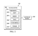
- heating system 122 includes one or more of components 200. These components are configured to generate flow 130 of heated air 124 within airfoil model 110 in a manner that simulates flow 126 of heated air 128 in inlet 104 of aircraft engine 106 in Figure 1 .
- components 200 may include at least one of duct 202, nozzle 204, valve 206, flow orifice 208, plenum 210, heated air source 212, and other suitable components.
- the phrase "at least one of,” when used with a list of items, means different combinations of one or more of the listed items may be used and only one of each item in the list may be needed.
- “at least one of item A, item B, and item C” may include, without limitation, item A or item A and item B. This example also may include item A, item B, and item C, or item B and item C.
- "at least one of” may be, for example, without limitation, two of item A, one of item B, and ten of item C; four of item B and seven of item C; and other suitable combinations.
- one or more of components 200 may be located within interior 132 of airfoil model 110 in Figure 1 .
- Duct 202 is a structure with an enclosed passage for conveying a flow of a fluid such as flow 130 of heated air 124.
- Duct 202 may be rigid or flexible depending on the particular implementation.
- Nozzle 204 is a component having an opening configured to regulate flow 130 of heated air 124, direct flow 130 of heated air 124, or both.
- nozzle 204 may have various sizes and configurations to provide flow 130 of heated air 124 in a desired manner.
- valve 206 is configured to be associated with duct 202.
- Valve 206 is configured to control flow 130 of heated air 124 within duct 202 in these illustrative examples. Valve 206 may be adjusted prior to flow 130 of heated air 124 being generated within interior 132 of airfoil model 110, while flow 130 of heated air 124 flows within interior 132 of airfoil model 110, or a combination of the two.
- flow orifice 208 is configured to be associated with duct 202 and is a structure configured to change the diameter of a location in duct 202. Flow orifice 208 may be used to increase flow rate 140 of heated air 124 within a portion of duct 202. Further, flow orifice 208 may be placed downstream of valve 206. In this location, flow orifice 208 may be used to adjust flow 130 of heated air 124 from valve 206 more precisely. For example, flow orifice 208 may be configured to increase flow rate 140 of flow 130 of heated air 124 coming from valve 206.
- plenum 210 is a structure that may take the form of a plate or gate. Plenum 210 may be placed in duct 202 or at an end of duct 202. Plenum 210 is configured to control airflow by increasing friction in duct 202.
- Components 200 may be made of various types of materials.
- components 200 may be comprised of polycarbonate, plastic, aluminum, polyvinyl chloride, and other suitable materials. These materials may be selected based on an ability of the materials to perform as desired in circulating heated air 124 within airfoil model 110.
- Heated air source 212 is configured to generate flow 130 of heated air 124 in heating system 122.
- components 200 in heating system 122 may be connected to heated air source 212 to provide flow 130 of heated air 124 within interior 132 of airfoil model 110.
- components 200 in heating system 122 are configured to control flow 130 of heated air 124 such that flow 130 of heated air 124 substantially matches air, such as heated air 128 flowing from aircraft engine 106 through inlet 104 for the portion of inlet 104 that airfoil model 110 represents.
- flow 130 of heated air 124 may simulate a circulation of heated air 128 within interior 134 of inlet 104. Heated air 128 may travel around interior 134 of inlet 104 for some period of time in these illustrative examples.
- heated air 124 may simulate heated air from an auxiliary power unit in the aircraft rather than heated air 128 from aircraft engine 106.
- icing simulation environment 100 and the various components such as components 200 for heating system 122 in Figure 1 and Figure 2 are not meant to imply physical or architectural limitations to the manner in which an illustrative embodiment may be implemented. Other components in addition to or in place of the ones illustrated may be used. Some components may be unnecessary. Also, the blocks are presented to illustrate some functional components. One or more of these blocks may be combined, divided, or combined and divided into different blocks when implemented in an illustrative embodiment.
- heated air source 212 may be considered part of heating system 122 rather than as a separate component from heating system 122. In still other illustrative examples, heated air source 212 may be considered part of wind tunnel 116. In yet other illustrative examples, airfoil model 110 also may include a portion of the housing for aircraft engine 106 in addition to inlet 104.
- test object 102 may be a portion of a wing, a horizontal stabilizer, a vertical stabilizer, or some other suitable structure in which air flows within the structure from a source in the aircraft for purposes of providing icing protection.
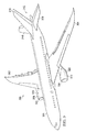
- aircraft 300 has wing 302 and wing 304 attached to body 306.
- Aircraft 300 includes engine 308 attached to wing 302 and engine 310 attached to wing 304.
- Body 306 has tail section 312.
- Horizontal stabilizer 314, horizontal stabilizer 316, and vertical stabilizer 318 are attached to tail section 312 of body 306.
- Aircraft 300 is an example of an aircraft in which an icing protection system may be located, and which may be simulated in icing simulation environment 100 in Figure 1 .
- engine 308 has housing 319 with inlet 320.
- Engine 310 has housing 322 with inlet 324.
- Inlet 320 and inlet 324 are examples of physical implementations for inlet 104 shown in block form in Figure 1 .
- These inlets may have a certain interior shape configured to provide icing protection on those portions of aircraft 300 when heated air, such as bleed air from an engine or heated air from an auxiliary power unit, is sent through the interiors of inlet 320 and inlet 324.
- heated air such as bleed air from an engine or heated air from an auxiliary power unit
- air may flow within the interior of inlet 320 and inlet 324 in a manner that reduces the formation of ice, prevents the formation of ice, and melts any ice that may form on the surface of inlet 320 and inlet 324 due to icing conditions in these illustrative examples.
- An airfoil model such as airfoil model 110 in Figure 1 , may be created for inlet 320 and inlet 324 and tested to determine whether the inlet designs provide a desired level of icing protection.
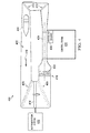
- FIG. 4 an illustration of a wind tunnel in which icing conditions may be simulated is depicted in accordance with an illustrative embodiment.
- a top view of wind tunnel 400 is shown.
- Wind tunnel 400 is an example of one implementation of wind tunnel 116 in Figure 1 .
- interior 402 of wind tunnel 400 has airflow generator 404, turning vane 406, turning vane 408, turning vane 410, turning vane 412, heat exchanger 414, spray bars 416, and other suitable components.
- airflow generator 404 is configured to generate airflow 418 within interior 402 of wind tunnel 400.
- Airflow generator 404 includes a fan system in this illustrative example.
- Turning vanes 406, 408, 410, and 412 are configured to aid in directing airflow 418 within interior 402 of wind tunnel 400.
- Heat exchanger 414 is connected to refrigeration system 420. Refrigeration system 420 with heat exchanger 414 is configured to cool air within airflow 418. Spray bars 416 are configured to generate drops of water 422 to simulate icing conditions within interior 402 of wind tunnel 400. Drops of water 422 may be supercooled drops in these illustrative examples.
- test section 424 is the portion of wind tunnel 400 in which a test object may be placed for testing.
- the test object takes the form of an airfoil model, such as airfoil model 110 in Figure 1 .
- wind tunnel 400 also may include heated air source 426. Heated air source 426 is configured to generate heated air that may be directed to the test object in these illustrative examples. The operation of wind tunnel 400 is controlled in control room 428.
- wind tunnel 400 in Figure 4 is only presented as an illustrative example of one manner in which wind tunnel 116 in Figure 1 may be implemented. This example is not meant to imply limitations to the manner in which wind tunnel 116 may be implemented for use in testing test object 102, such as airfoil model 110 of inlet 104.
- other wind tunnels may have other shapes or configurations.
- other wind tunnels may include additional airflow generators in addition to airflow generator 404 and may include other numbers of turning vanes.
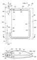
- airfoil model 500 is an example of one physical implementation for airfoil model 110 in Figure 1 .
- airfoil model 500 is an example of a cross section for inlet 320 or inlet 324 on aircraft 300 in Figure 3 .
- Airfoil model 500 may be placed into test section 424 of wind tunnel 400 for simulating icing conditions.
- airfoil model 500 with leading edge cross section 502 represents the geometry for inlet 320.
- Airfoil model 500 has leading edge 504 and trailing edge 506.
- airfoil model 500 has surface 508 defined by structure 510. Additionally, airfoil model 500 has interior 512 and interior 514. These two interiors are defined by structure 516, which is shown in phantom in this illustration. Structure 516 may be, for example, a bulk head.
- leading edge cross section 502 matches a leading edge curvature for inlet 320.
- section 518 has a curvature that substantially conforms to a cross section of the leading edge curvature for inlet 320.
- airfoil model 500 is substantially planar in the direction of arrow 520 rather than curved.
- airfoil model 500 also may have a curve in the direction of arrow 520 to match a radial curve for inlet 320.
- a radial curve for inlet 320 is a curve around an axis extending centrally through engine 310 in Figure 3 .
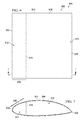
- FIG. 6 an illustration of a top view of an airfoil model is depicted in accordance with an illustrative embodiment.
- a top view of airfoil model 500 in Figure 5 is shown.
- FIG 7 an illustration of a cross section of an airfoil model is depicted in accordance with an illustrative embodiment.
- a cross-sectional view of airfoil model 500 is shown taken along lines 7-7 in Figure 6 .
- Airfoil model 500 as shown in Figures 5-7 is an example of an airfoil model in which a heating system may be implemented to generate a flow of heated air within interior 512 of airfoil model 500.
- heating system 800 is an example of one implementation for heating system 122 shown in block form in Figure 1 and Figure 2 .
- airfoil model 500 is shown in phantom to better illustrate components in heating system 800.
- heating system 800 includes duct system 802, nozzle system 804, valve system 806, plenum 808, and orifice 810.
- Duct system 802 includes duct 812, duct 814, and duct 816.
- Duct 812 and duct 816 are associated with each other.
- Duct 814 is connected to a heated air source not shown in this illustration.
- duct system 802 may be insulated to reduce heat loss from a duct to the internal cavity or structure of airfoil model 500 to a desired level. In this manner, a desired level of heat transfer may be provided to simulate the recirculation of heated air within an inlet.
- Valve system 806 includes valve 818 and valve 820. Valve 818 is located in duct 812, while valve 820 is located in duct 816. In this illustrative example, orifice 810 is located within duct 812. Plenum 808 is connected to duct 816. Nozzle system 804 includes nozzle 822 and nozzle 824.
- Nozzle 824 introduces heated air 825 into interior 512 of airfoil model 500.
- Nozzle 822 also may be configured to adjust the speed of the air flowing back into interior 512.
- Nozzle 824 injects heated air 825, and nozzle 822 injects recirculated air in these illustrative examples.
- Heated air 825 flows in the direction of arrow 826. As heated air 825 flows within interior 512, the heated air heats surface 508 of airfoil model 500 in section 518.
- Heated air 825 may be collected by plenum 808. Depending on the state of valve 820 and valve 818, heated air 825 may flow from plenum 808 into at least one of the direction of arrow 828 and in the direction of arrow 830. When valve 818 is open, heated air 825 flows in the direction of arrow 828. When valve 820 is open, heated air 825 flows in the direction of arrow 830. Valve 818 and valve 820 may be controlled to adjust the flow of heated air 825 in the direction of arrow 828 and in the direction of arrow 830.
- Heated air 825 flows in the direction of arrow 828 to simulate the circulation of heated air 825 within an inlet.
- heated air 825 flows in the direction of arrow 828 in duct 812, heated air 825 is returned to interior 512 by nozzle 822.
- the flow of heated air 825 in the direction of arrow 828 is controlled using valve 818 upstream of orifice 810. These components may control the amount of heated air 825 and the speed of heated air 825 that flows through duct 812. With duct 812, heated air 825 flowing within duct 812 may become cooler.
- duct 812 along with valve 818, orifice 810, and nozzle 822 are configured to simulate various parameters within an inlet.
- these components may be used to simulate the cooling and speed at which heated air 825 flows within the interior of an inlet as heated air 825 recirculates within the inlet.
- Valve 820 in duct 816 may be configured to simulate the exit of heated air 825 from an inlet.
- FIG. 9 an illustration of a top view of an airfoil model with a heating system is depicted in accordance with an illustrative embodiment. As depicted, a top view of airfoil model 500 with heating system 800 from Figure 8 is shown.
- FIG. 10 an illustration of a cross-sectional view of an airfoil model with a heating system is depicted in accordance with an illustrative embodiment.
- a cross-sectional view of airfoil model 500 with heating system 800 is shown in a cross-sectional view taken along lines 10-10 in Figure 9 .
- heating system 1100 is an example of another configuration for a heating system that may be used in airfoil model 500.
- heating system 1100 may be one configuration for heating system 122 in Figure 1 .
- duct system 1102 is only present within interior 512 of airfoil model 500 and not within interior 514 of airfoil model 500.
- structure 510 and structure 516 are shown in phantom to illustrate various components for heating system 1100.
- heating system 1100 includes duct system 1102, nozzle system 1104, valve system 1106, plenum 1108, and orifice 1110.
- duct system 1102 includes duct 1112, duct 1114, and duct 1116.
- Nozzle system 1104 includes nozzle 1118 and nozzle 1120.
- Valve system 1106 includes valve 1122 and valve 1124.
- Duct 1114 in duct system 1102 is connected to a heated air source not shown in this illustration.
- Duct system 1102 may be insulated to reduce heat loss to a desired level.
- Nozzle 1120 introduces heated air 1125 in the direction of arrow 1126 into interior 512 of airfoil model 500. Heated air 1125 enters plenum 1108 and may travel in at least one of the direction of arrow 1128 and in the direction of arrow 1130. These directions are controlled by valve 1122 and valve 1124 in duct 1112 and duct 1116, respectively.
- duct 1112 is located outside of structure 510.
- duct 1112 may extend into the interior of the wind tunnel farther beyond and outside of the wind tunnel walls as needed to simulate the length of the engine air duct used in the aircraft to obtain heated air from the aircraft engine.
- Duct 1112 may be insulated to reduce the amount of cooling may occur. The amount of insulation and the length of duct 1112 is configured to simulate the flow of air within inlet 320 in Figure 3 .
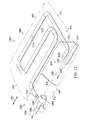
- heating system 1200 includes duct system 1202, nozzle system 1204, valve system 1206, plenum 1208, and orifice 1210.
- duct system 1202 includes duct 1212, duct 1214, and duct 1216.
- Duct system 1202 may be insulated to reduce heat loss to a desired level. Materials for insulation of duct system 1202 may be selected from at least one of fiberglass, foam, and other suitable materials.
- Nozzle system 1204 includes nozzle 1218 and nozzle 1220. Nozzle 1218 is associated with duct 1212 and nozzle 1220 is associated with duct 1214.
- Valve system 1206 includes valve 1222 and valve 1224. Valve 1222 is located in duct 1212 and valve 1224 is located in duct 1216. Plenum 1208 is associated with duct 1216. Orifice 1210 is located within duct 1212.
- duct 1214 is connected to a heated air source not shown in this illustration and provides flow of heated air 1225 in the direction of arrow 1226.
- Plenum 1208 may receive heated air 1225 flowing within interior 512 in airfoil model 500 and heated air 1225 may travel in at least one of the direction of arrow 1228 and in the direction of arrow 1230 as controlled by valve 1222 and valve 1224, respectively.
- duct system 1202 is located within airfoil model 500.
- Duct 1212 has a shape and configuration to simulate the flow of air around inlet 320 in Figure 3 .
- the length of duct 1212 is selected to simulate the distance that the heated air flows around inlet 320 to return to the cross section of inlet 320 as modeled by leading edge cross section 502 of airfoil model 500.
- airfoil model 500 and the different heating systems that may be used with airfoil model 500 in Figures 5-12 are not meant to imply limitations to the manner in which other illustrative embodiments may be implemented.
- the different configurations of heating systems are presented only as illustrations of some examples of implementations for heating system 122 shown in block form in Figure 1 and Figure 2 .
- Other heating systems may include other components in addition to or in place of the ones illustrated as well as other configurations for the components illustrated in the figures.
- an additional duct with another nozzle may be included in addition to the nozzle used to introduce air into airfoil model 500 from a heated air source.
- more than one duct may be used to recirculate air within airfoil model 500 rather than the single duct as illustrated in these examples.
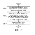
- FIG. 13 an illustration of a flowchart of a process for generating a flow of heated air in an airfoil model of an inlet for an aircraft is depicted in accordance with an illustrative embodiment.
- the process illustrated in Figure 13 may be implemented in icing simulation environment 100 in Figure 1 .
- the process may be implemented using heating system 122 for airfoil model 110 in Figure 1 .
- the process begins by sending heated air into a duct system associated with an airfoil model of an inlet of an aircraft engine (operation 1300).
- the process then circulates the heated air within the airfoil model of the inlet of the aircraft engine using the duct system in a manner that simulates air flowing in the inlet of the aircraft engine (operation 1302).
- the process then exposes the airfoil model to an icing condition (operation 1304), with the process terminating thereafter.
- the airfoil model may be subjected to an icing condition in a wind tunnel configured to generate icing conditions.
- the airfoil model may be mounted onto an aircraft and flown in actual icing conditions.
- each block in the flowcharts or block diagrams may represent a module, segment, function, and/or a portion of an operation or step.
- the function or functions noted in the blocks may occur out of the order noted in the figures.
- two blocks shown in succession may be executed substantially concurrently, or the blocks may sometimes be performed in the reverse order, depending upon the functionality involved.
- other blocks may be added in addition to the illustrated blocks in a flowchart or block diagram.
- operation 1304 may be performed prior to operation 1302.
- both operation 1302 and operation 1304 may be performed at the same time.
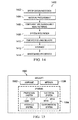
- Illustrative embodiments of the disclosure may be described in the context of aircraft manufacturing and service method 1400 as shown in Figure 14 and aircraft 1500 as shown in Figure 15 . Testing of airfoil model 110 may occur during one of the phases of manufacturing and service method 1400.
- aircraft manufacturing and service method 1400 may include specification and design 1402 of aircraft 1500 in Figure 15 and material procurement 1404.
- aircraft 1500 in Figure 15 During production, component and subassembly manufacturing 1406 and system integration 1408 of aircraft 1500 in Figure 15 takes place. Thereafter, aircraft 1500 in Figure 15 may go through certification and delivery 1410 in order to be placed in service 1412. While in service 1412 by a customer, aircraft 1500 in Figure 15 is scheduled for routine maintenance and service 1414, which may include modification, reconfiguration, refurbishment, and other maintenance or service.
- Each of the processes of aircraft manufacturing and service method 1400 may be performed or carried out by a system integrator, a third party, and/or an operator.
- the operator may be a customer.
- a system integrator may include, without limitation, any number of aircraft manufacturers and major-system subcontractors
- a third party may include, without limitation, any number of vendors, subcontractors, and suppliers
- an operator may be an airline, a leasing company, a military entity, a service organization, and so on.
- Aircraft 1500 may be one example of aircraft 108 in Figure 1 and aircraft 300 in Figure 3 .
- aircraft 1500 is produced by aircraft manufacturing and service method 1400 in Figure 14 and may include airframe 1502 with plurality of systems 1504 and interior 1506.
- systems 1504 include one or more of propulsion system 1508, electrical system 1510, hydraulic system 1512, and environmental system 1514. Any number of other systems may be included.
- propulsion system 1508 include one or more of propulsion system 1508, electrical system 1510, hydraulic system 1512, and environmental system 1514. Any number of other systems may be included.
- an aerospace example is shown, different illustrative embodiments may be applied to other industries, such as the automotive industry.
- Apparatuses and methods embodied herein may be employed during at least one of the stages of aircraft manufacturing and service method 1400 in Figure 14 .
- One or more illustrative embodiments may be implemented during specification and design 1402 to test designs of icing protection systems used aircraft 1500.
- one or more illustrative embodiments may be used during certification and delivery 1410 to certify that icing protection designs may perform as desired. Further, one or more illustrative embodiments may be used during maintenance and service 1414 when new icing conditions are designed or implemented in aircraft 1500 during maintenance, upgrades, refurbishment, or other operations performed on aircraft 1500.
- the illustrative embodiments provide a method and apparatus for simulating an ice protection system in a wind tunnel that generates icing conditions.
- the illustrative embodiments may be used to simulate an icing protection system for an inlet for the aircraft engine that uses heated air to provide icing protection.
- the illustrative examples may reduce the complexity and time needed to simulate icing conditions for an airfoil model for the inlet.
- the illustrative embodiments provide a more accurate simulation of the operation of an icing protection system as compared to using electric heater mats that are installed on the inner surface of the leading edge of an airfoil model. In this manner, the illustrative embodiments may use actual airflow and temperatures that may be found in bleed air from an engine, heated air from an auxiliary power unit, or other sources in an aircraft.
- the illustrative embodiments also provide an ability to replicate the flow of heated air. This replication includes the flow rate, the distance that the heated air flows in the inlet, and the circular routing of the heated air within the interior of the inlet. As a result, the illustrative embodiments provide more accurate results and may reduce the amount of flight testing needed to determine whether an icing protection system performs as desired.
Landscapes
- Physics & Mathematics (AREA)
- General Physics & Mathematics (AREA)
- Fluid Mechanics (AREA)
- Engineering & Computer Science (AREA)
- Aviation & Aerospace Engineering (AREA)
- Aerodynamic Tests, Hydrodynamic Tests, Wind Tunnels, And Water Tanks (AREA)
Applications Claiming Priority (1)
| Application Number | Priority Date | Filing Date | Title |
|---|---|---|---|
| US13/598,223 US9134196B2 (en) | 2012-08-29 | 2012-08-29 | Inlet icing protection simulation system |
Publications (3)
| Publication Number | Publication Date |
|---|---|
| EP2703291A2 true EP2703291A2 (fr) | 2014-03-05 |
| EP2703291A3 EP2703291A3 (fr) | 2015-09-02 |
| EP2703291B1 EP2703291B1 (fr) | 2017-05-10 |
Family
ID=48700376
Family Applications (1)
| Application Number | Title | Priority Date | Filing Date |
|---|---|---|---|
| EP13174077.1A Active EP2703291B1 (fr) | 2012-08-29 | 2013-06-27 | Système de simulation de protection contre le givrage d'entrée d'air |
Country Status (2)
| Country | Link |
|---|---|
| US (1) | US9134196B2 (fr) |
| EP (1) | EP2703291B1 (fr) |
Cited By (6)
| Publication number | Priority date | Publication date | Assignee | Title |
|---|---|---|---|---|
| CN109596302A (zh) * | 2018-11-02 | 2019-04-09 | 中国航空工业集团公司西安飞机设计研究所 | 一种飞行器模型低速风洞实验的流量控制引射系统 |
| CN110411702A (zh) * | 2019-07-11 | 2019-11-05 | 中国空气动力研究与发展中心低速空气动力研究所 | 结冰风洞防除冰供气系统的高压气源供气管路 |
| CN110411703A (zh) * | 2019-07-11 | 2019-11-05 | 中国空气动力研究与发展中心低速空气动力研究所 | 结冰风洞防除冰供气系统 |
| CN113029499A (zh) * | 2021-03-26 | 2021-06-25 | 中国空气动力研究与发展中心超高速空气动力研究所 | 一种高超声速风洞大尺度模块化试验段的现场安装工艺 |
| CN114166460A (zh) * | 2022-02-11 | 2022-03-11 | 中国空气动力研究与发展中心低速空气动力研究所 | 飞行器进气道试验装置、系统和热气防冰试验判稳方法 |
| CN121163812A (zh) * | 2025-11-24 | 2025-12-19 | 中国空气动力研究与发展中心高速空气动力研究所 | 一种高速风洞进气道试验运行与流场控制方法 |
Families Citing this family (6)
| Publication number | Priority date | Publication date | Assignee | Title |
|---|---|---|---|---|
| FR2993003B1 (fr) * | 2012-07-06 | 2016-10-21 | Snecma | Dispositif de simulation d'une introduction de paquets de glace dans un moteur |
| US10138811B2 (en) * | 2014-03-13 | 2018-11-27 | The Boeing Company | Enhanced temperature control anti-ice nozzle |
| US9696238B2 (en) * | 2014-09-16 | 2017-07-04 | The Boeing Company | Systems and methods for icing flight tests |
| CN105021372B (zh) * | 2015-08-04 | 2017-12-22 | 中国航天空气动力技术研究院 | 风洞自由飞模型相似设计方法 |
| CN115508096B (zh) * | 2021-06-23 | 2025-07-15 | 中国航发商用航空发动机有限责任公司 | 流道模拟件、防冰试验装置和防冰试验方法 |
| CN117241417B (zh) * | 2023-11-08 | 2024-01-19 | 中国空气动力研究与发展中心低速空气动力研究所 | 一种飞机进气道前缘电热防冰热载荷试验方法 |
Family Cites Families (3)
| Publication number | Priority date | Publication date | Assignee | Title |
|---|---|---|---|---|
| US4688745A (en) | 1986-01-24 | 1987-08-25 | Rohr Industries, Inc. | Swirl anti-ice system |
| FR2774035B1 (fr) * | 1998-01-29 | 2000-03-31 | Valeo Climatisation | Dispositif de chauffage et/ou climatisation de vehicule automobile, avec gestion amelioree de l'echange thermique |
| ES2596505T3 (es) * | 2001-08-07 | 2017-01-10 | Toray Industries, Inc. | Procedimiento para la fabricación de un elemento de PRF grande |
-
2012
- 2012-08-29 US US13/598,223 patent/US9134196B2/en active Active
-
2013
- 2013-06-27 EP EP13174077.1A patent/EP2703291B1/fr active Active
Non-Patent Citations (1)
| Title |
|---|
| None |
Cited By (8)
| Publication number | Priority date | Publication date | Assignee | Title |
|---|---|---|---|---|
| CN109596302A (zh) * | 2018-11-02 | 2019-04-09 | 中国航空工业集团公司西安飞机设计研究所 | 一种飞行器模型低速风洞实验的流量控制引射系统 |
| CN110411702A (zh) * | 2019-07-11 | 2019-11-05 | 中国空气动力研究与发展中心低速空气动力研究所 | 结冰风洞防除冰供气系统的高压气源供气管路 |
| CN110411703A (zh) * | 2019-07-11 | 2019-11-05 | 中国空气动力研究与发展中心低速空气动力研究所 | 结冰风洞防除冰供气系统 |
| CN113029499A (zh) * | 2021-03-26 | 2021-06-25 | 中国空气动力研究与发展中心超高速空气动力研究所 | 一种高超声速风洞大尺度模块化试验段的现场安装工艺 |
| CN113029499B (zh) * | 2021-03-26 | 2022-04-12 | 中国空气动力研究与发展中心超高速空气动力研究所 | 一种高超声速风洞大尺度模块化试验段的现场安装工艺 |
| CN114166460A (zh) * | 2022-02-11 | 2022-03-11 | 中国空气动力研究与发展中心低速空气动力研究所 | 飞行器进气道试验装置、系统和热气防冰试验判稳方法 |
| CN114166460B (zh) * | 2022-02-11 | 2022-04-19 | 中国空气动力研究与发展中心低速空气动力研究所 | 飞行器进气道试验装置、系统和热气防冰试验判稳方法 |
| CN121163812A (zh) * | 2025-11-24 | 2025-12-19 | 中国空气动力研究与发展中心高速空气动力研究所 | 一种高速风洞进气道试验运行与流场控制方法 |
Also Published As
| Publication number | Publication date |
|---|---|
| EP2703291B1 (fr) | 2017-05-10 |
| US20140060166A1 (en) | 2014-03-06 |
| EP2703291A3 (fr) | 2015-09-02 |
| US9134196B2 (en) | 2015-09-15 |
Similar Documents
| Publication | Publication Date | Title |
|---|---|---|
| EP2703291B1 (fr) | Système de simulation de protection contre le givrage d'entrée d'air | |
| US10907546B2 (en) | Cross-stream heat exchanger | |
| US9328650B2 (en) | Engine cooling system | |
| EP3057869B1 (fr) | Système et procédé anti-givrage pour les aéronefs | |
| EP2650665B1 (fr) | Système de simulation d'état de givrage de large goutte en surfusion | |
| CA2848491C (fr) | Methodes et dispositif de melange de debits d'air dans les systemes de controle environnemental | |
| Shen et al. | Three-dimensional numerical simulation of ice accretion at the engine inlet | |
| Romani et al. | Cabin temperature control model for commercial aircraft | |
| CN107152996A (zh) | 一种用于风洞试验的矢量推进飞机模型 | |
| Zhaoguang et al. | Study of power influences to the wing-mounted civil aircraft aerodynamic characteristics | |
| CN113955146A (zh) | 一种防冰冷负荷分布试验的模拟装置 | |
| US9187180B2 (en) | Thermal pneumatic deicing system for an aircraft RAM air heat exchanger | |
| Veillard et al. | Icing simulation in multistage jet engines | |
| Tetteh et al. | Experimental study of an anti-icing system for stator and inlet guide vanes | |
| Butler | Aircraft crown compartment thermal management: the influence of internal heat dissipating elements | |
| CN111504593A (zh) | 适用于空气舵射流风洞试验的固定工装 | |
| Harrison | Active flow control of a boundary layer ingesting serpentine diffuser | |
| Liu et al. | Optimization for Hot-film Anti-icing Structure by BPNN and GA | |
| CN119821675A (zh) | 一种飞机风挡的防冰系统 | |
| Xie et al. | Numerical simulation on the ventilation cooling performance of the engine nacelle under hover and forward flight conditions | |
| Wang et al. | Analysis of Civil Aircraft Fuselage Ventilation Drag Influenced by Engine Jet Flow | |
| Humphreys et al. | Flight testing of a HLF wing with suction, ice-protection and anti-contamination systems | |
| KASIM | THE EFFECT OF IMPINGEMENT HOT AIR ON TEMPERATURE DISTRIBUTION OF THE FLAT PLATE | |
| Pottanam Selvarajan et al. | Optimising Oil-Cooler Duct Position for a Pusher Type Turboprop Aircraft | |
| Andreozzi et al. | Thermal and Fluid Dynamic Analysis on Impinging Jet for Aircraft Anti-Icing |
Legal Events
| Date | Code | Title | Description |
|---|---|---|---|
| AK | Designated contracting states |
Kind code of ref document: A2 Designated state(s): AL AT BE BG CH CY CZ DE DK EE ES FI FR GB GR HR HU IE IS IT LI LT LU LV MC MK MT NL NO PL PT RO RS SE SI SK SM TR |
|
| AX | Request for extension of the european patent |
Extension state: BA ME |
|
| PUAI | Public reference made under article 153(3) epc to a published international application that has entered the european phase |
Free format text: ORIGINAL CODE: 0009012 |
|
| PUAL | Search report despatched |
Free format text: ORIGINAL CODE: 0009013 |
|
| AK | Designated contracting states |
Kind code of ref document: A3 Designated state(s): AL AT BE BG CH CY CZ DE DK EE ES FI FR GB GR HR HU IE IS IT LI LT LU LV MC MK MT NL NO PL PT RO RS SE SI SK SM TR |
|
| AX | Request for extension of the european patent |
Extension state: BA ME |
|
| RIC1 | Information provided on ipc code assigned before grant |
Ipc: B64D 15/04 20060101AFI20150724BHEP |
|
| 17P | Request for examination filed |
Effective date: 20160223 |
|
| RBV | Designated contracting states (corrected) |
Designated state(s): AL AT BE BG CH CY CZ DE DK EE ES FI FR GB GR HR HU IE IS IT LI LT LU LV MC MK MT NL NO PL PT RO RS SE SI SK SM TR |
|
| GRAP | Despatch of communication of intention to grant a patent |
Free format text: ORIGINAL CODE: EPIDOSNIGR1 |
|
| INTG | Intention to grant announced |
Effective date: 20160621 |
|
| GRAJ | Information related to disapproval of communication of intention to grant by the applicant or resumption of examination proceedings by the epo deleted |
Free format text: ORIGINAL CODE: EPIDOSDIGR1 |
|
| GRAP | Despatch of communication of intention to grant a patent |
Free format text: ORIGINAL CODE: EPIDOSNIGR1 |
|
| INTC | Intention to grant announced (deleted) | ||
| INTG | Intention to grant announced |
Effective date: 20161121 |
|
| GRAS | Grant fee paid |
Free format text: ORIGINAL CODE: EPIDOSNIGR3 |
|
| GRAA | (expected) grant |
Free format text: ORIGINAL CODE: 0009210 |
|
| AK | Designated contracting states |
Kind code of ref document: B1 Designated state(s): AL AT BE BG CH CY CZ DE DK EE ES FI FR GB GR HR HU IE IS IT LI LT LU LV MC MK MT NL NO PL PT RO RS SE SI SK SM TR |
|
| REG | Reference to a national code |
Ref country code: GB Ref legal event code: FG4D |
|
| REG | Reference to a national code |
Ref country code: AT Ref legal event code: REF Ref document number: 892034 Country of ref document: AT Kind code of ref document: T Effective date: 20170515 Ref country code: CH Ref legal event code: EP |
|
| REG | Reference to a national code |
Ref country code: IE Ref legal event code: FG4D |
|
| REG | Reference to a national code |
Ref country code: DE Ref legal event code: R096 Ref document number: 602013020858 Country of ref document: DE |
|
| REG | Reference to a national code |
Ref country code: FR Ref legal event code: PLFP Year of fee payment: 5 |
|
| REG | Reference to a national code |
Ref country code: NL Ref legal event code: MP Effective date: 20170510 |
|
| REG | Reference to a national code |
Ref country code: LT Ref legal event code: MG4D |
|
| REG | Reference to a national code |
Ref country code: AT Ref legal event code: MK05 Ref document number: 892034 Country of ref document: AT Kind code of ref document: T Effective date: 20170510 |
|
| PG25 | Lapsed in a contracting state [announced via postgrant information from national office to epo] |
Ref country code: AT Free format text: LAPSE BECAUSE OF FAILURE TO SUBMIT A TRANSLATION OF THE DESCRIPTION OR TO PAY THE FEE WITHIN THE PRESCRIBED TIME-LIMIT Effective date: 20170510 Ref country code: ES Free format text: LAPSE BECAUSE OF FAILURE TO SUBMIT A TRANSLATION OF THE DESCRIPTION OR TO PAY THE FEE WITHIN THE PRESCRIBED TIME-LIMIT Effective date: 20170510 Ref country code: LT Free format text: LAPSE BECAUSE OF FAILURE TO SUBMIT A TRANSLATION OF THE DESCRIPTION OR TO PAY THE FEE WITHIN THE PRESCRIBED TIME-LIMIT Effective date: 20170510 Ref country code: NO Free format text: LAPSE BECAUSE OF FAILURE TO SUBMIT A TRANSLATION OF THE DESCRIPTION OR TO PAY THE FEE WITHIN THE PRESCRIBED TIME-LIMIT Effective date: 20170810 Ref country code: FI Free format text: LAPSE BECAUSE OF FAILURE TO SUBMIT A TRANSLATION OF THE DESCRIPTION OR TO PAY THE FEE WITHIN THE PRESCRIBED TIME-LIMIT Effective date: 20170510 Ref country code: GR Free format text: LAPSE BECAUSE OF FAILURE TO SUBMIT A TRANSLATION OF THE DESCRIPTION OR TO PAY THE FEE WITHIN THE PRESCRIBED TIME-LIMIT Effective date: 20170811 Ref country code: HR Free format text: LAPSE BECAUSE OF FAILURE TO SUBMIT A TRANSLATION OF THE DESCRIPTION OR TO PAY THE FEE WITHIN THE PRESCRIBED TIME-LIMIT Effective date: 20170510 |
|
| PG25 | Lapsed in a contracting state [announced via postgrant information from national office to epo] |
Ref country code: LV Free format text: LAPSE BECAUSE OF FAILURE TO SUBMIT A TRANSLATION OF THE DESCRIPTION OR TO PAY THE FEE WITHIN THE PRESCRIBED TIME-LIMIT Effective date: 20170510 Ref country code: NL Free format text: LAPSE BECAUSE OF FAILURE TO SUBMIT A TRANSLATION OF THE DESCRIPTION OR TO PAY THE FEE WITHIN THE PRESCRIBED TIME-LIMIT Effective date: 20170510 Ref country code: PL Free format text: LAPSE BECAUSE OF FAILURE TO SUBMIT A TRANSLATION OF THE DESCRIPTION OR TO PAY THE FEE WITHIN THE PRESCRIBED TIME-LIMIT Effective date: 20170510 Ref country code: BG Free format text: LAPSE BECAUSE OF FAILURE TO SUBMIT A TRANSLATION OF THE DESCRIPTION OR TO PAY THE FEE WITHIN THE PRESCRIBED TIME-LIMIT Effective date: 20170810 Ref country code: SE Free format text: LAPSE BECAUSE OF FAILURE TO SUBMIT A TRANSLATION OF THE DESCRIPTION OR TO PAY THE FEE WITHIN THE PRESCRIBED TIME-LIMIT Effective date: 20170510 Ref country code: RS Free format text: LAPSE BECAUSE OF FAILURE TO SUBMIT A TRANSLATION OF THE DESCRIPTION OR TO PAY THE FEE WITHIN THE PRESCRIBED TIME-LIMIT Effective date: 20170510 Ref country code: IS Free format text: LAPSE BECAUSE OF FAILURE TO SUBMIT A TRANSLATION OF THE DESCRIPTION OR TO PAY THE FEE WITHIN THE PRESCRIBED TIME-LIMIT Effective date: 20170910 |
|
| PG25 | Lapsed in a contracting state [announced via postgrant information from national office to epo] |
Ref country code: RO Free format text: LAPSE BECAUSE OF FAILURE TO SUBMIT A TRANSLATION OF THE DESCRIPTION OR TO PAY THE FEE WITHIN THE PRESCRIBED TIME-LIMIT Effective date: 20170510 Ref country code: CZ Free format text: LAPSE BECAUSE OF FAILURE TO SUBMIT A TRANSLATION OF THE DESCRIPTION OR TO PAY THE FEE WITHIN THE PRESCRIBED TIME-LIMIT Effective date: 20170510 Ref country code: SK Free format text: LAPSE BECAUSE OF FAILURE TO SUBMIT A TRANSLATION OF THE DESCRIPTION OR TO PAY THE FEE WITHIN THE PRESCRIBED TIME-LIMIT Effective date: 20170510 Ref country code: EE Free format text: LAPSE BECAUSE OF FAILURE TO SUBMIT A TRANSLATION OF THE DESCRIPTION OR TO PAY THE FEE WITHIN THE PRESCRIBED TIME-LIMIT Effective date: 20170510 Ref country code: DK Free format text: LAPSE BECAUSE OF FAILURE TO SUBMIT A TRANSLATION OF THE DESCRIPTION OR TO PAY THE FEE WITHIN THE PRESCRIBED TIME-LIMIT Effective date: 20170510 |
|
| REG | Reference to a national code |
Ref country code: CH Ref legal event code: PL |
|
| REG | Reference to a national code |
Ref country code: DE Ref legal event code: R097 Ref document number: 602013020858 Country of ref document: DE |
|
| PG25 | Lapsed in a contracting state [announced via postgrant information from national office to epo] |
Ref country code: IT Free format text: LAPSE BECAUSE OF FAILURE TO SUBMIT A TRANSLATION OF THE DESCRIPTION OR TO PAY THE FEE WITHIN THE PRESCRIBED TIME-LIMIT Effective date: 20170510 Ref country code: SM Free format text: LAPSE BECAUSE OF FAILURE TO SUBMIT A TRANSLATION OF THE DESCRIPTION OR TO PAY THE FEE WITHIN THE PRESCRIBED TIME-LIMIT Effective date: 20170510 |
|
| PLBE | No opposition filed within time limit |
Free format text: ORIGINAL CODE: 0009261 |
|
| STAA | Information on the status of an ep patent application or granted ep patent |
Free format text: STATUS: NO OPPOSITION FILED WITHIN TIME LIMIT |
|
| REG | Reference to a national code |
Ref country code: IE Ref legal event code: MM4A |
|
| 26N | No opposition filed |
Effective date: 20180213 |
|
| PG25 | Lapsed in a contracting state [announced via postgrant information from national office to epo] |
Ref country code: CH Free format text: LAPSE BECAUSE OF NON-PAYMENT OF DUE FEES Effective date: 20170630 Ref country code: LU Free format text: LAPSE BECAUSE OF NON-PAYMENT OF DUE FEES Effective date: 20170627 Ref country code: IE Free format text: LAPSE BECAUSE OF NON-PAYMENT OF DUE FEES Effective date: 20170627 Ref country code: LI Free format text: LAPSE BECAUSE OF NON-PAYMENT OF DUE FEES Effective date: 20170630 |
|
| PG25 | Lapsed in a contracting state [announced via postgrant information from national office to epo] |
Ref country code: SI Free format text: LAPSE BECAUSE OF FAILURE TO SUBMIT A TRANSLATION OF THE DESCRIPTION OR TO PAY THE FEE WITHIN THE PRESCRIBED TIME-LIMIT Effective date: 20170510 |
|
| REG | Reference to a national code |
Ref country code: BE Ref legal event code: MM Effective date: 20170630 |
|
| REG | Reference to a national code |
Ref country code: FR Ref legal event code: PLFP Year of fee payment: 6 |
|
| PG25 | Lapsed in a contracting state [announced via postgrant information from national office to epo] |
Ref country code: BE Free format text: LAPSE BECAUSE OF NON-PAYMENT OF DUE FEES Effective date: 20170630 |
|
| PG25 | Lapsed in a contracting state [announced via postgrant information from national office to epo] |
Ref country code: MT Free format text: LAPSE BECAUSE OF NON-PAYMENT OF DUE FEES Effective date: 20170627 |
|
| PG25 | Lapsed in a contracting state [announced via postgrant information from national office to epo] |
Ref country code: HU Free format text: LAPSE BECAUSE OF FAILURE TO SUBMIT A TRANSLATION OF THE DESCRIPTION OR TO PAY THE FEE WITHIN THE PRESCRIBED TIME-LIMIT; INVALID AB INITIO Effective date: 20130627 Ref country code: MC Free format text: LAPSE BECAUSE OF FAILURE TO SUBMIT A TRANSLATION OF THE DESCRIPTION OR TO PAY THE FEE WITHIN THE PRESCRIBED TIME-LIMIT Effective date: 20170510 |
|
| PG25 | Lapsed in a contracting state [announced via postgrant information from national office to epo] |
Ref country code: CY Free format text: LAPSE BECAUSE OF NON-PAYMENT OF DUE FEES Effective date: 20170510 |
|
| PG25 | Lapsed in a contracting state [announced via postgrant information from national office to epo] |
Ref country code: MK Free format text: LAPSE BECAUSE OF FAILURE TO SUBMIT A TRANSLATION OF THE DESCRIPTION OR TO PAY THE FEE WITHIN THE PRESCRIBED TIME-LIMIT Effective date: 20170510 |
|
| PG25 | Lapsed in a contracting state [announced via postgrant information from national office to epo] |
Ref country code: TR Free format text: LAPSE BECAUSE OF FAILURE TO SUBMIT A TRANSLATION OF THE DESCRIPTION OR TO PAY THE FEE WITHIN THE PRESCRIBED TIME-LIMIT Effective date: 20170510 |
|
| PG25 | Lapsed in a contracting state [announced via postgrant information from national office to epo] |
Ref country code: PT Free format text: LAPSE BECAUSE OF FAILURE TO SUBMIT A TRANSLATION OF THE DESCRIPTION OR TO PAY THE FEE WITHIN THE PRESCRIBED TIME-LIMIT Effective date: 20170510 |
|
| PG25 | Lapsed in a contracting state [announced via postgrant information from national office to epo] |
Ref country code: AL Free format text: LAPSE BECAUSE OF FAILURE TO SUBMIT A TRANSLATION OF THE DESCRIPTION OR TO PAY THE FEE WITHIN THE PRESCRIBED TIME-LIMIT Effective date: 20170510 |
|
| P01 | Opt-out of the competence of the unified patent court (upc) registered |
Effective date: 20230516 |
|
| PGFP | Annual fee paid to national office [announced via postgrant information from national office to epo] |
Ref country code: GB Payment date: 20260629 Year of fee payment: 14 |
|
| PGFP | Annual fee paid to national office [announced via postgrant information from national office to epo] |
Ref country code: DE Payment date: 20260629 Year of fee payment: 14 |
|
| PGFP | Annual fee paid to national office [announced via postgrant information from national office to epo] |
Ref country code: FR Payment date: 20260625 Year of fee payment: 14 |