EP2703290A2 - Air transmission system for flexible passenger supply units - Google Patents
Air transmission system for flexible passenger supply units Download PDFInfo
- Publication number
- EP2703290A2 EP2703290A2 EP13179022.2A EP13179022A EP2703290A2 EP 2703290 A2 EP2703290 A2 EP 2703290A2 EP 13179022 A EP13179022 A EP 13179022A EP 2703290 A2 EP2703290 A2 EP 2703290A2
- Authority
- EP
- European Patent Office
- Prior art keywords
- air
- air supply
- supply line
- tap opening
- individual
- Prior art date
- Legal status (The legal status is an assumption and is not a legal conclusion. Google has not performed a legal analysis and makes no representation as to the accuracy of the status listed.)
- Granted
Links
- 230000005540 biological transmission Effects 0.000 title 1
- QVGXLLKOCUKJST-UHFFFAOYSA-N atomic oxygen Chemical compound [O] QVGXLLKOCUKJST-UHFFFAOYSA-N 0.000 claims description 4
- 229910052760 oxygen Inorganic materials 0.000 claims description 4
- 239000001301 oxygen Substances 0.000 claims description 4
- 230000003287 optical effect Effects 0.000 claims description 3
- 238000003825 pressing Methods 0.000 claims description 2
- 238000003860 storage Methods 0.000 description 7
- 238000005253 cladding Methods 0.000 description 5
- 238000009826 distribution Methods 0.000 description 3
- 230000001419 dependent effect Effects 0.000 description 2
- 239000002313 adhesive film Substances 0.000 description 1
- 230000001276 controlling effect Effects 0.000 description 1
- 238000009434 installation Methods 0.000 description 1
- 230000003993 interaction Effects 0.000 description 1
- 238000000034 method Methods 0.000 description 1
- 230000001105 regulatory effect Effects 0.000 description 1
- 238000009420 retrofitting Methods 0.000 description 1
- 238000010079 rubber tapping Methods 0.000 description 1
Images



Classifications
-
- B—PERFORMING OPERATIONS; TRANSPORTING
- B64—AIRCRAFT; AVIATION; COSMONAUTICS
- B64D—EQUIPMENT FOR FITTING IN OR TO AIRCRAFT; FLIGHT SUITS; PARACHUTES; ARRANGEMENT OR MOUNTING OF POWER PLANTS OR PROPULSION TRANSMISSIONS IN AIRCRAFT
- B64D13/00—Arrangements or adaptations of air-treatment apparatus for aircraft crew or passengers, or freight space
- B64D13/02—Arrangements or adaptations of air-treatment apparatus for aircraft crew or passengers, or freight space the air being pressurised
-
- B—PERFORMING OPERATIONS; TRANSPORTING
- B64—AIRCRAFT; AVIATION; COSMONAUTICS
- B64D—EQUIPMENT FOR FITTING IN OR TO AIRCRAFT; FLIGHT SUITS; PARACHUTES; ARRANGEMENT OR MOUNTING OF POWER PLANTS OR PROPULSION TRANSMISSIONS IN AIRCRAFT
- B64D13/00—Arrangements or adaptations of air-treatment apparatus for aircraft crew or passengers, or freight space
-
- B—PERFORMING OPERATIONS; TRANSPORTING
- B64—AIRCRAFT; AVIATION; COSMONAUTICS
- B64D—EQUIPMENT FOR FITTING IN OR TO AIRCRAFT; FLIGHT SUITS; PARACHUTES; ARRANGEMENT OR MOUNTING OF POWER PLANTS OR PROPULSION TRANSMISSIONS IN AIRCRAFT
- B64D13/00—Arrangements or adaptations of air-treatment apparatus for aircraft crew or passengers, or freight space
- B64D13/06—Arrangements or adaptations of air-treatment apparatus for aircraft crew or passengers, or freight space the air being conditioned
- B64D2013/0603—Environmental Control Systems
- B64D2013/0625—Environmental Control Systems comprising means for distribution effusion of conditioned air in the cabin
Definitions
- the invention relates to an air supply system for passengers in a passenger compartment, for example of an aircraft.
- the invention relates to a system for transmitting air in passenger supply units (passenger supply unit/PSU), which can be flexibly arranged relative to a central air supply line.
- passenger supply unit/PSU passenger supply unit
- DE 10 2010 012 882 B3 shows a system for supplying individual air with an air line and a sliding individual air panel.
- the air line has a tubular element with a slotted opening formed in the longitudinal direction, and a lamellar element, which is suitable for closing the slotted opening.
- the individual air panel has a housing, an air nozzle for controlling individual air on the front side of the housing, and a cantilever arm on the rear side of the housing for displacing the lamellar element, and thereby partially opening the air line, as well as an opening for receiving air from the air line.
- Described in DE 10 2007 014 406 B3 is a supply channel with an air distribution system that comprises an oblong housing, a hollow profile extending in the longitudinal direction of the housing, and at least one air shower with an air inlet and at least one air outlet.
- a plurality of perforation openings is incorporated in a jacket surface of the hollow profile.
- the air shower is designed in such a way as to abut tightly against the jacket surface of the hollow profile in one area of the air inlet.
- Perforation openings emptying into an air inlet of an air shower can be sealed by means of an adhesive film applied thereto.
- the supply channel makes it possible to variably position air showers along the longitudinal direction of the supply channel.
- One object of the invention is to provide an air supply system that can be easily adjusted to a modified seat layout.
- an air supply system for passengers comprises an air supply line and an individual air panel with at least one air nozzle.
- the air supply line can be fitted with a plurality of laterally situated air outlets, which are spaced apart at uniform distances from each other.
- the individual air panel comprises an air tap opening with a width and length, wherein the length is several times greater than the width.
- the individual air panel can be variably positioned in the longitudinal direction on the air supply line in such a way that the air tap opening in the longitudinal direction is arranged parallel to the air supply line, and that the air tap opening covers at least one air outlet. In this way, air can flow out of the air supply line through the air outlet and air tap opening to the air nozzle.
- the air flows out of the air outlet only at one other location in the longitudinal air tap opening. If the individual air panel is shifted beyond the length of the air tap opening, the latter can already come to cover the next air outlet.
- the air supply system enables a distribution of individual air panels without having to specially adjust the individual air supply.
- a flexible interface between the individual air panels and aircraft air supply system or climate control system permits an individual air supply at any longitudinal coordinate of the aircraft cabin. An operator thus has the option of selecting any seat spacing configuration desired, without having to reposition the supply channel. Instead, he or she can simply shift the individual air panels or give them a staggered arrangement.
- each of the air outlets can incorporate a valve, and an actuating element for opening the valve can be arranged on the air tap opening of the individual air panel, wherein the actuating element can be designed in such a way as to open the valve when the individual air panel is positioned on the air supply line.
- the valve can be a check valve, which can be situated in an air outlet in such a way that the check valve plunger is outwardly directed.
- the actuating element can be designed as a rib or bar, which is suitable for inwardly pressing the plunger, and thereby opening the check valve.
- the air supply system can further comprise an attachment rail, wherein the individual air panel can be secured to the attachment rail in such a way that it can be shifted along the air supply line.
- the actuating element can here be suitable for opening an air outlet if the air tap opening is pushed over the air outlet, i.e., when the actuating element interacts with an element, for example a check valve, which closes the air outlet.
- the distance between two air outlets is slightly greater than the length of the air tap opening.
- the air tap opening always covers precisely one air outlet when continuously shifted along the supply line.
- the individual air panel can be positioned on the air supply line at one of several predetermined positions spaced apart at uniform distances from each other along the air supply line, wherein the positions are predetermined in such a way that the air tap opening always completely covers precisely one air outlet.
- the individual air panel can also comprise a reading light, a stewardess call button, a loudspeaker, a USB interface for transmitting information and/or energy, an oxygen mask, an oxygen generator and/or an optical display element, so that the individual air panel comprises additional functionalities of a passenger supply unit (PSU).
- PSU passenger supply unit
- the air supply system can also comprise an air treatment unit that provides air with a desired humidity and temperature and/or filtered air, and routes it to the individual air panel through the air supply line.
- the aircraft comprises an air supply system as described herein for supplying passengers with individual inlet air.
- the air supply system can also be used in any means of passenger conveyance, for example in a bus, a railway car, or a ship.
- Fig. 1 shows a longitudinal section through a passenger cabin of an aircraft.
- a plurality of seat rows 40 are arranged in the passenger cabin.
- hat racks or storage compartments 30 are situated over the seat rows.
- passenger supply units 20 to supply the passengers with signals, information, electrical or electronic connections, as well as fresh air.
- air nozzles 22 allocated to each individual seat row are provided, and situated on a passenger supply channel spaced a corresponding distance apart from each other.
- Fig. 2 is a cross section through a storage compartment 30, wherein cladding elements 50 are provided under the storage compartment. In roughly the middle under the storage compartment, the cladding elements 50 form a recess 55 suitable for accommodating at least one passenger supply unit (PSU) 20.
- An air supply line 10 is located on one side of the recess 55.
- the air supply line 10 has at least one valve 14, which is set up to regulate a flow of air from the air supply line 10 into the PSU 20.
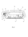
- Fig. 3 provides a detailed view of the arrangement of a PSU20 in a recess 55.
- the PSU 20 can comprise an air tap opening 24 on a side facing the air supply line, i.e., an element open toward the air supply line.
- the valve 14 in the air supply line 10 can be actuated in such a way that air flows from the air supply line and through the air tap opening into the PSU. The inflowing air inside the PSU can then be routed to air nozzles 22.
- Fig. 2 and 3 show gaps between the cladding elements 50 that form the recess 55.
- Rails 52 for suspending and shifting the PSU can be provide in these gaps.
- Corresponding meshing elements 53 secured to the PSU 20 can engage into the rails 52.
- Fig. 4 presents a potential embodiment of a passenger supply unit (PSU) 20, wherein in particular the air supply arrangements are shown.
- the PSU 20 comprises an air tap opening 24, an air guiding element like a hose 28, as well as several air nozzles 22.
- the PSU 20 can further be set up to accommodate additional elements for supplying passengers with optical or acoustic signals or with energy.
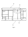
- Fig. 5 presents an alternative embodiment of a PSU 20 with an air tap opening 224 and air nozzles 22.
- the flow of air from the air tap opening 24 can be routed via integrally formed channels in the PSU housing to the air nozzles 22. It can here also be provided that additional functionalities be integrated into the PSU.
- Fig. 5 further shows a section of a channel formed by the recess 55 in the cladding under a storage compartment. Situated on one side of the recess 55 parallel to the recess, which can be formed in the longitudinal direction of the passenger cabin, is an air supply line 10, which is provided at regular intervals with air outlets, wherein these air outlets are closed as regulated by valves 14.
- Fig. 6 depicts an element for tapping air from the air supply line, i.e., an air tap opening.
- an element can be designed as a separate element or be an integral part of the housing of a PSU.
- the element has an opening with length L and width B, wherein the length L is several times greater than width B.
- the length L can be 5 to 9 times, preferably about 7 times greater than the width B.
- the length L can measure about 12 inches (30.5 cm), and the width B about 1.5 inches (3.8 cm).
- a rib 26 is situated in the opening in the longitudinal direction.
- the rib 26 is supported and reinforced by a plurality of braces 27.
- a plurality of braces 27 In the embodiment on Fig.
- the rib 26 is centrally located transverse to the longitudinal direction, and designed roughly flush with the outer edge of the opening.
- a rib arranged in this way can be used to press a protruding end of a check valve plunger back far enough to open the check valve.
- a seal 25 can be provided to prevent air from uncontrollably flowing past the air tap opening. As soon as the air tap opening is situated parallel to an air supply line in the longitudinal direction, and a check valve is opened by means of the rib 26, air can flow out of the air supply line into the air tap opening, and be relayed further through an outlet opening 29 in the direction of one or more air nozzles.
- Fig. 7 presents a view intended to illustrate the interaction between an air tap opening 24 and check valve 14.
- the air tap opening 24 is arranged in such a way relative to the valve 14 on an air supply line 10 that the rib 26 supported by braces 27 exerts a force F on the plunger 16 of the check valve 14, and presses the plunger back against the restoring force of the spring 17.
- the air outlet 12 is opened, and air can flow out of the air supply line 10 (as symbolized by the two arrows).
- Fig. 8 presents a diagrammatic view of a motion grid for a PSU with an air tap opening 24 relative to an air supply line 10.
- air outlets 12 Spaced apart by distance D from each other in the air supply line are air outlets 12, wherein these air outlets 12 can each be sealed, for example with a check valve.
- the distance D is greater than the length L of the air tap opening, so that only one air outlet 12 is covered by the air tap opening at any one time. For example, if the distance D measures about 14 inches (35.5 cm) and the length L 12 inches (30.5 cm), it can be ensured after at least every 2 inches (5 cm) that the air tap opening covers an air outlet 12, and opens a valve in the air outlet, for example by means of a rib.
Landscapes
- Health & Medical Sciences (AREA)
- General Health & Medical Sciences (AREA)
- Pulmonology (AREA)
- Engineering & Computer Science (AREA)
- Aviation & Aerospace Engineering (AREA)
- Duct Arrangements (AREA)
Abstract
Description
- The invention relates to an air supply system for passengers in a passenger compartment, for example of an aircraft. In particular, the invention relates to a system for transmitting air in passenger supply units (passenger supply unit/PSU), which can be flexibly arranged relative to a central air supply line.
-
DE 10 2010 012 882 B3 shows a system for supplying individual air with an air line and a sliding individual air panel. The air line has a tubular element with a slotted opening formed in the longitudinal direction, and a lamellar element, which is suitable for closing the slotted opening. The individual air panel has a housing, an air nozzle for controlling individual air on the front side of the housing, and a cantilever arm on the rear side of the housing for displacing the lamellar element, and thereby partially opening the air line, as well as an opening for receiving air from the air line. - Described in
DE 10 2007 014 406 B3 - However, the problem in such air distribution systems is that the air showers or air nozzles must be adjusted to the respective seat positions, which significantly hampers installation in the cabin equipment and retrofitting. This greatly limits the flexibility of the cabin configuration, since the aircraft reference documentation and connecting points must be determined very early on in the definition process.
- One object of the invention is to provide an air supply system that can be easily adjusted to a modified seat layout. These and other objects are achieved by the subject matter of the independent claim. Additional embodiments are described in the dependent claims.
- In general, an air supply system for passengers comprises an air supply line and an individual air panel with at least one air nozzle. The air supply line can be fitted with a plurality of laterally situated air outlets, which are spaced apart at uniform distances from each other. The individual air panel comprises an air tap opening with a width and length, wherein the length is several times greater than the width. According to the invention, the individual air panel can be variably positioned in the longitudinal direction on the air supply line in such a way that the air tap opening in the longitudinal direction is arranged parallel to the air supply line, and that the air tap opening covers at least one air outlet. In this way, air can flow out of the air supply line through the air outlet and air tap opening to the air nozzle.
- If the position of the individual air panel is changed in the longitudinal direction, the air flows out of the air outlet only at one other location in the longitudinal air tap opening. If the individual air panel is shifted beyond the length of the air tap opening, the latter can already come to cover the next air outlet.
- The air supply system enables a distribution of individual air panels without having to specially adjust the individual air supply. A flexible interface between the individual air panels and aircraft air supply system or climate control system permits an individual air supply at any longitudinal coordinate of the aircraft cabin. An operator thus has the option of selecting any seat spacing configuration desired, without having to reposition the supply channel. Instead, he or she can simply shift the individual air panels or give them a staggered arrangement.
- In an embodiment, each of the air outlets can incorporate a valve, and an actuating element for opening the valve can be arranged on the air tap opening of the individual air panel, wherein the actuating element can be designed in such a way as to open the valve when the individual air panel is positioned on the air supply line.
- For example, the valve can be a check valve, which can be situated in an air outlet in such a way that the check valve plunger is outwardly directed. For example, the actuating element can be designed as a rib or bar, which is suitable for inwardly pressing the plunger, and thereby opening the check valve.
- In a further embodiment, the air supply system can further comprise an attachment rail, wherein the individual air panel can be secured to the attachment rail in such a way that it can be shifted along the air supply line. The actuating element can here be suitable for opening an air outlet if the air tap opening is pushed over the air outlet, i.e., when the actuating element interacts with an element, for example a check valve, which closes the air outlet.
- In another embodiment of the air supply system, the distance between two air outlets is slightly greater than the length of the air tap opening. As a result of this constellation, the air tap opening always covers precisely one air outlet when continuously shifted along the supply line.
- In an embodiment, the individual air panel can be positioned on the air supply line at one of several predetermined positions spaced apart at uniform distances from each other along the air supply line, wherein the positions are predetermined in such a way that the air tap opening always completely covers precisely one air outlet.
- In a further embodiment, the individual air panel can also comprise a reading light, a stewardess call button, a loudspeaker, a USB interface for transmitting information and/or energy, an oxygen mask, an oxygen generator and/or an optical display element, so that the individual air panel comprises additional functionalities of a passenger supply unit (PSU).
- In another embodiment, the air supply system can also comprise an air treatment unit that provides air with a desired humidity and temperature and/or filtered air, and routes it to the individual air panel through the air supply line.
- In an embodiment, the aircraft comprises an air supply system as described herein for supplying passengers with individual inlet air. Let it here be noted that the air supply system can also be used in any means of passenger conveyance, for example in a bus, a railway car, or a ship.
- The aspects described above along with other aspects, features and advantages of the invention can also be gleaned from the exemplary embodiments, which are described below with reference to the attached drawings.
-
-
Fig. 1 is a longitudinal section through a passenger cabin. -
Fig. 2 is a cross section through a passenger supply channel under a storage compartment. -
Fig. 3 is a cross section through an individual air panel and an air supply line. -
Fig. 4 shows an individual air panel according to an embodiment. -
Fig. 5 shows an individual air panel according to another embodiment. -
Fig. 6 is an isometric view of an air tap opening of an individual air panel. -
Fig. 7 is a sectional view of a check valve together with an air tap opening. -
Fig. 8 shows a motion grid for an individual air panel on an air supply line. - On the figures, identical reference numbers are used for the same or at least similar elements, components or aspects. Let it be noted that the embodiments to be described in detail below are only illustrative, and not limiting.
-
Fig. 1 shows a longitudinal section through a passenger cabin of an aircraft. A plurality ofseat rows 40 are arranged in the passenger cabin. Situated over the seat rows are hat racks orstorage compartments 30 along withpassenger supply units 20 to supply the passengers with signals, information, electrical or electronic connections, as well as fresh air. As depicted onFig. 1 ,air nozzles 22 allocated to each individual seat row are provided, and situated on a passenger supply channel spaced a corresponding distance apart from each other. -
Fig. 2 is a cross section through astorage compartment 30, whereincladding elements 50 are provided under the storage compartment. In roughly the middle under the storage compartment, thecladding elements 50 form arecess 55 suitable for accommodating at least one passenger supply unit (PSU) 20. Anair supply line 10 is located on one side of therecess 55. Theair supply line 10 has at least onevalve 14, which is set up to regulate a flow of air from theair supply line 10 into thePSU 20. -
Fig. 3 provides a detailed view of the arrangement of a PSU20 in arecess 55. As shown onFig. 3 , thePSU 20 can comprise an air tap opening 24 on a side facing the air supply line, i.e., an element open toward the air supply line. As soon as aPSU 20 becomes situated in therecess 55, thevalve 14 in theair supply line 10 can be actuated in such a way that air flows from the air supply line and through the air tap opening into the PSU. The inflowing air inside the PSU can then be routed toair nozzles 22. -
Fig. 2 and3 show gaps between thecladding elements 50 that form therecess 55.Rails 52 for suspending and shifting the PSU can be provide in these gaps. Corresponding meshingelements 53 secured to thePSU 20 can engage into therails 52. -
Fig. 4 presents a potential embodiment of a passenger supply unit (PSU) 20, wherein in particular the air supply arrangements are shown. ThePSU 20 comprises anair tap opening 24, an air guiding element like ahose 28, as well asseveral air nozzles 22. ThePSU 20 can further be set up to accommodate additional elements for supplying passengers with optical or acoustic signals or with energy. -
Fig. 5 presents an alternative embodiment of aPSU 20 with an air tap opening 224 andair nozzles 22. In this embodiment, the flow of air from the air tap opening 24 can be routed via integrally formed channels in the PSU housing to theair nozzles 22. It can here also be provided that additional functionalities be integrated into the PSU. -
Fig. 5 further shows a section of a channel formed by therecess 55 in the cladding under a storage compartment. Situated on one side of therecess 55 parallel to the recess, which can be formed in the longitudinal direction of the passenger cabin, is anair supply line 10, which is provided at regular intervals with air outlets, wherein these air outlets are closed as regulated byvalves 14. -
Fig. 6 depicts an element for tapping air from the air supply line, i.e., an air tap opening. Such an element can be designed as a separate element or be an integral part of the housing of a PSU. As evident fromFig. 6 , the element has an opening with length L and width B, wherein the length L is several times greater than width B. For example, the length L can be 5 to 9 times, preferably about 7 times greater than the width B. For example, the length L can measure about 12 inches (30.5 cm), and the width B about 1.5 inches (3.8 cm). Arib 26 is situated in the opening in the longitudinal direction. Therib 26 is supported and reinforced by a plurality ofbraces 27. In the embodiment onFig. 6 , therib 26 is centrally located transverse to the longitudinal direction, and designed roughly flush with the outer edge of the opening. A rib arranged in this way can be used to press a protruding end of a check valve plunger back far enough to open the check valve. - A
seal 25 can be provided to prevent air from uncontrollably flowing past the air tap opening. As soon as the air tap opening is situated parallel to an air supply line in the longitudinal direction, and a check valve is opened by means of therib 26, air can flow out of the air supply line into the air tap opening, and be relayed further through anoutlet opening 29 in the direction of one or more air nozzles. -
Fig. 7 presents a view intended to illustrate the interaction between anair tap opening 24 andcheck valve 14. Theair tap opening 24 is arranged in such a way relative to thevalve 14 on anair supply line 10 that therib 26 supported bybraces 27 exerts a force F on theplunger 16 of thecheck valve 14, and presses the plunger back against the restoring force of thespring 17. In this way, theair outlet 12 is opened, and air can flow out of the air supply line 10 (as symbolized by the two arrows). -
Fig. 8 presents a diagrammatic view of a motion grid for a PSU with an air tap opening 24 relative to anair supply line 10. Spaced apart by distance D from each other in the air supply line areair outlets 12, wherein theseair outlets 12 can each be sealed, for example with a check valve. The distance D is greater than the length L of the air tap opening, so that only oneair outlet 12 is covered by the air tap opening at any one time. For example, if the distance D measures about 14 inches (35.5 cm) and thelength L 12 inches (30.5 cm), it can be ensured after at least every 2 inches (5 cm) that the air tap opening covers anair outlet 12, and opens a valve in the air outlet, for example by means of a rib. - While the invention was illustrated and described in detail in the drawings and above specification, it is intended that such illustrations and descriptions merely be illustrative or exemplary, and not restrictive, so that the invention is not limited by the disclosed embodiments. In the claims, the word "comprising" does not preclude other elements, and the indeterminate article "one" does not rule out a plurality.
- Just the fact that certain features are mentioned in various dependent claims does not in itself limit the subject matter of the invention. Combinations of these features can also be advantageously used. The references in the claims are not to limit the scope of the claims.
-
- 10
- Air supply line
- 12
- Air outlet
- 14
- Valve
- 16
- Plunger
- 17
- Spring
- 20
- Individual air panel
- 22
- Air nozzle
- 24
- Air tap opening
- 25
- Seal
- 26
- Rib
- 27
- Brace
- 28
- Hose
- 29
- Outlet opening
- 30
- Storage compartment
- 40
- Seat row
- 50
- Cladding
- 52
- Rail
- 53
- Meshing element
- 55
- Recess
- B
- Width
- D
- Distance
- F
- Force
- L
- Length
Claims (10)
- An air supply system for passengers, comprising:an air supply line (10) with a plurality of laterally situated air outlets (11), which are spaced apart at uniform distances (D) from each other,an individual air panel (20) with at least one air nozzle (22) and one air tap opening (24), which comprises a width (B) and length (L), wherein the length of the air tap opening is several times greater than the width of the air tap opening, and wherein the individual air panel can be variably positioned in the longitudinal direction on the air supply line in such a way that the air tap opening in the longitudinal direction is arranged parallel to the air supply line, and that the air tap opening covers an air outlet, so that air can flow out of the air supply line through the air outlet and air tap opening to the air nozzle.
- The air supply system according to claim 1, wherein each of the air outlets (12) includes a valve (14), and wherein an actuating element (26) for opening the valve is arranged on the air tap opening (24), wherein the actuating element opens the valve when the individual air panel (20) is positioned on the air supply line (10).
- The air supply system according to claim 2, wherein the valve is a check valve, wherein the check valve is situated in an air outlet (12) in such a way that a plunger of the check valve is outwardly directed, and wherein the actuating element is suitable for inwardly pressing the plunger, and thereby opening the check valve.
- The air supply system according to one of claims 1 to 3, further comprising an attachment rail (52), wherein the individual air panel (20) is secured to the attachment rail in such a way that it can be shifted along the air supply line (10).
- The air supply system according to claim 4, wherein the actuating element (26) is suitable for opening an air outlet (12) when the air tap opening (24) is shifted over the air outlet.
- The air supply system according to one of claims 1 to 5, wherein the distance (D) between two air outlets (12) is slightly greater than the length (L) of the air tap opening (24).
- The air supply system according to one of claims 1 to 6, wherein the individual air panel (20) can be positioned on the air supply line at one of several predetermined positions spaced apart at uniform distances from each other along the air supply line (10), wherein the positions are predetermined in such a way that the air tap opening (24) always completely covers precisely one air outlet (12).
- The air supply system according to claim 1, wherein the individual air panel (20) further comprises at least one element from a group comprised of a reading lamp, stewardess call button, loudspeaker, USB interface, optical display element, oxygen mask and oxygen generator.
- The air supply system according to claim 1, which further comprises an air treatment unit.
- An aircraft with an air supply system according to claim 1 for supplying passengers with individual inlet air.
Applications Claiming Priority (2)
| Application Number | Priority Date | Filing Date | Title |
|---|---|---|---|
| US201261695330P | 2012-08-31 | 2012-08-31 | |
| DE102012017349.0A DE102012017349A1 (en) | 2012-08-31 | 2012-08-31 | Air transmission system for flexible passenger supply units |
Publications (3)
| Publication Number | Publication Date |
|---|---|
| EP2703290A2 true EP2703290A2 (en) | 2014-03-05 |
| EP2703290A3 EP2703290A3 (en) | 2017-11-08 |
| EP2703290B1 EP2703290B1 (en) | 2018-10-10 |
Family
ID=48915895
Family Applications (1)
| Application Number | Title | Priority Date | Filing Date |
|---|---|---|---|
| EP13179022.2A Not-in-force EP2703290B1 (en) | 2012-08-31 | 2013-08-02 | Air transmission system for flexible passenger supply units |
Country Status (3)
| Country | Link |
|---|---|
| US (1) | US9630721B2 (en) |
| EP (1) | EP2703290B1 (en) |
| DE (1) | DE102012017349A1 (en) |
Families Citing this family (2)
| Publication number | Priority date | Publication date | Assignee | Title |
|---|---|---|---|---|
| DE102014101895A1 (en) | 2014-02-14 | 2015-08-20 | Airbus Operations Gmbh | Interior component for a vehicle with a modular passenger supply unit |
| US11290793B2 (en) * | 2019-07-23 | 2022-03-29 | AAC Technologies Pte. Ltd. | Sounding device and mobile terminal |
Citations (2)
| Publication number | Priority date | Publication date | Assignee | Title |
|---|---|---|---|---|
| DE102007014406B3 (en) | 2007-03-26 | 2008-04-24 | Airbus Deutschland Gmbh | Supply channel for supplying fresh air and/or air-conditioned air to seat of vehicle i.e. airplane, has air shower designed for sealingly fitting at mantle surface of hollow profile in area of air inlet |
| DE102010012882B3 (en) | 2010-03-26 | 2011-07-28 | Airbus Operations GmbH, 21129 | Air line for use in air supply system that is utilized for supplying air to individual passenger in aircraft, has strip-like element supported at inner side wall of hollow section, so that airflow is enabled out from hollow section |
Family Cites Families (9)
| Publication number | Priority date | Publication date | Assignee | Title |
|---|---|---|---|---|
| DE4301681C1 (en) * | 1993-01-22 | 1994-10-20 | Deutsche Aerospace Airbus | Pipe branch between an air line and an air shower |
| DE102005053696B4 (en) * | 2005-11-10 | 2009-05-14 | Airbus Deutschland Gmbh | Emergency ram air inlet flap of an aircraft |
| FR2915788B1 (en) * | 2007-05-04 | 2012-05-25 | Airbus France | DEVICE FOR CONNECTING MULTI-SYSTEMS ON BOARD AN AIRCRAFT |
| US9561855B2 (en) * | 2008-05-01 | 2017-02-07 | The Boeing Company | Alternate directional momentum ventilation nozzle for passenger cabins |
| DE102008062703A1 (en) * | 2008-12-17 | 2010-07-01 | Airbus Deutschland Gmbh | Aircraft cabin panel for sound absorption |
| DE102009014599A1 (en) * | 2009-03-24 | 2010-09-30 | Airbus Deutschland Gmbh | Integration of supply functions in a storage compartment |
| DE102010008626A1 (en) * | 2010-02-19 | 2011-08-25 | Airbus Operations GmbH, 21129 | Supply air supply for passengers in aircraft |
| DE102010018502A1 (en) * | 2010-04-28 | 2011-11-03 | Airbus Operations Gmbh | Supply system for supplying passengers in a passenger compartment of a vehicle |
| DE102010052157A1 (en) * | 2010-11-22 | 2012-05-24 | Airbus Operations Gmbh | Ventilation system and aircraft air conditioning |
-
2012
- 2012-08-31 DE DE102012017349.0A patent/DE102012017349A1/en not_active Withdrawn
-
2013
- 2013-08-02 EP EP13179022.2A patent/EP2703290B1/en not_active Not-in-force
- 2013-08-27 US US14/010,756 patent/US9630721B2/en not_active Expired - Fee Related
Patent Citations (2)
| Publication number | Priority date | Publication date | Assignee | Title |
|---|---|---|---|---|
| DE102007014406B3 (en) | 2007-03-26 | 2008-04-24 | Airbus Deutschland Gmbh | Supply channel for supplying fresh air and/or air-conditioned air to seat of vehicle i.e. airplane, has air shower designed for sealingly fitting at mantle surface of hollow profile in area of air inlet |
| DE102010012882B3 (en) | 2010-03-26 | 2011-07-28 | Airbus Operations GmbH, 21129 | Air line for use in air supply system that is utilized for supplying air to individual passenger in aircraft, has strip-like element supported at inner side wall of hollow section, so that airflow is enabled out from hollow section |
Also Published As
| Publication number | Publication date |
|---|---|
| DE102012017349A1 (en) | 2014-03-06 |
| US20140065937A1 (en) | 2014-03-06 |
| US9630721B2 (en) | 2017-04-25 |
| EP2703290B1 (en) | 2018-10-10 |
| EP2703290A3 (en) | 2017-11-08 |
Similar Documents
| Publication | Publication Date | Title |
|---|---|---|
| DE102011116884B4 (en) | Passenger service module and passenger service system | |
| EP2139707B1 (en) | Supply channel comprising an air distribution system for vehicles, aircraft having such a supply channel, and method for producing a supply channel | |
| US5556332A (en) | Air duct for a position adjustable service panel | |
| US9487294B2 (en) | Supply system for supplying passengers in a passenger compartment of a vehicle | |
| JP4412562B2 (en) | Aircraft archway structure | |
| EP2801523B1 (en) | Passenger supply system for installation in a passenger supply channel | |
| EP2907751B1 (en) | Interior component for a vehicle with a modular passenger service unit | |
| US9834309B2 (en) | Air transmission system for flexible passenger supply units | |
| EP2703290B1 (en) | Air transmission system for flexible passenger supply units | |
| EP2536632B1 (en) | Inlet air supply for passengers in aircraft | |
| US20100087131A1 (en) | Integrated air supply device | |
| US20120129438A1 (en) | Ventilation system and aircraft air-conditioning system | |
| DE102010012882B3 (en) | Air line for use in air supply system that is utilized for supplying air to individual passenger in aircraft, has strip-like element supported at inner side wall of hollow section, so that airflow is enabled out from hollow section | |
| EP1848631B1 (en) | Arrangement of line connections for installations in an aircraft passenger cabin | |
| DE102010024265A1 (en) | Ventilation device for passenger cabin, particularly in airplane, has supply channel and multiple supply units having air outlet device | |
| WO2009149904A2 (en) | Aircraft system carrier element | |
| EP4737313A1 (en) | Aircraft section and aircraft comprising a freezing protection for a water line | |
| CN119262298A (en) | Aircraft having a drinking water system and method for installing a drinking water system in an aircraft | |
| CN121947767A (en) | Lateral air outlet for an aircraft cabin and aircraft with a lateral air outlet | |
| EP3168141B1 (en) | A cargo floor or wall for an aircraft | |
| US20120019944A1 (en) | Mirror arrangement for monitoring a passenger cabin of an aircraft | |
| EP3254966B1 (en) | Panel system for covering the ceiling portion of an aircraft cabin | |
| US20150008283A1 (en) | Aircraft seating unit with fixture member |
Legal Events
| Date | Code | Title | Description |
|---|---|---|---|
| AK | Designated contracting states |
Kind code of ref document: A2 Designated state(s): AL AT BE BG CH CY CZ DE DK EE ES FI FR GB GR HR HU IE IS IT LI LT LU LV MC MK MT NL NO PL PT RO RS SE SI SK SM TR |
|
| AX | Request for extension of the european patent |
Extension state: BA ME |
|
| PUAI | Public reference made under article 153(3) epc to a published international application that has entered the european phase |
Free format text: ORIGINAL CODE: 0009012 |
|
| PUAL | Search report despatched |
Free format text: ORIGINAL CODE: 0009013 |
|
| AK | Designated contracting states |
Kind code of ref document: A3 Designated state(s): AL AT BE BG CH CY CZ DE DK EE ES FI FR GB GR HR HU IE IS IT LI LT LU LV MC MK MT NL NO PL PT RO RS SE SI SK SM TR |
|
| AX | Request for extension of the european patent |
Extension state: BA ME |
|
| RIC1 | Information provided on ipc code assigned before grant |
Ipc: B64D 13/00 20060101AFI20170929BHEP |
|
| STAA | Information on the status of an ep patent application or granted ep patent |
Free format text: STATUS: REQUEST FOR EXAMINATION WAS MADE |
|
| 17P | Request for examination filed |
Effective date: 20180409 |
|
| RBV | Designated contracting states (corrected) |
Designated state(s): AL AT BE BG CH CY CZ DE DK EE ES FI FR GB GR HR HU IE IS IT LI LT LU LV MC MK MT NL NO PL PT RO RS SE SI SK SM TR |
|
| GRAP | Despatch of communication of intention to grant a patent |
Free format text: ORIGINAL CODE: EPIDOSNIGR1 |
|
| STAA | Information on the status of an ep patent application or granted ep patent |
Free format text: STATUS: GRANT OF PATENT IS INTENDED |
|
| INTG | Intention to grant announced |
Effective date: 20180622 |
|
| GRAS | Grant fee paid |
Free format text: ORIGINAL CODE: EPIDOSNIGR3 |
|
| GRAA | (expected) grant |
Free format text: ORIGINAL CODE: 0009210 |
|
| STAA | Information on the status of an ep patent application or granted ep patent |
Free format text: STATUS: THE PATENT HAS BEEN GRANTED |
|
| AK | Designated contracting states |
Kind code of ref document: B1 Designated state(s): AL AT BE BG CH CY CZ DE DK EE ES FI FR GB GR HR HU IE IS IT LI LT LU LV MC MK MT NL NO PL PT RO RS SE SI SK SM TR |
|
| REG | Reference to a national code |
Ref country code: GB Ref legal event code: FG4D |
|
| REG | Reference to a national code |
Ref country code: CH Ref legal event code: EP Ref country code: AT Ref legal event code: REF Ref document number: 1050928 Country of ref document: AT Kind code of ref document: T Effective date: 20181015 |
|
| REG | Reference to a national code |
Ref country code: IE Ref legal event code: FG4D |
|
| REG | Reference to a national code |
Ref country code: DE Ref legal event code: R096 Ref document number: 602013044758 Country of ref document: DE |
|
| REG | Reference to a national code |
Ref country code: NL Ref legal event code: MP Effective date: 20181010 |
|
| REG | Reference to a national code |
Ref country code: LT Ref legal event code: MG4D |
|
| REG | Reference to a national code |
Ref country code: AT Ref legal event code: MK05 Ref document number: 1050928 Country of ref document: AT Kind code of ref document: T Effective date: 20181010 |
|
| PG25 | Lapsed in a contracting state [announced via postgrant information from national office to epo] |
Ref country code: NL Free format text: LAPSE BECAUSE OF FAILURE TO SUBMIT A TRANSLATION OF THE DESCRIPTION OR TO PAY THE FEE WITHIN THE PRESCRIBED TIME-LIMIT Effective date: 20181010 |
|
| PG25 | Lapsed in a contracting state [announced via postgrant information from national office to epo] |
Ref country code: ES Free format text: LAPSE BECAUSE OF FAILURE TO SUBMIT A TRANSLATION OF THE DESCRIPTION OR TO PAY THE FEE WITHIN THE PRESCRIBED TIME-LIMIT Effective date: 20181010 Ref country code: LV Free format text: LAPSE BECAUSE OF FAILURE TO SUBMIT A TRANSLATION OF THE DESCRIPTION OR TO PAY THE FEE WITHIN THE PRESCRIBED TIME-LIMIT Effective date: 20181010 Ref country code: HR Free format text: LAPSE BECAUSE OF FAILURE TO SUBMIT A TRANSLATION OF THE DESCRIPTION OR TO PAY THE FEE WITHIN THE PRESCRIBED TIME-LIMIT Effective date: 20181010 Ref country code: LT Free format text: LAPSE BECAUSE OF FAILURE TO SUBMIT A TRANSLATION OF THE DESCRIPTION OR TO PAY THE FEE WITHIN THE PRESCRIBED TIME-LIMIT Effective date: 20181010 Ref country code: PL Free format text: LAPSE BECAUSE OF FAILURE TO SUBMIT A TRANSLATION OF THE DESCRIPTION OR TO PAY THE FEE WITHIN THE PRESCRIBED TIME-LIMIT Effective date: 20181010 Ref country code: BG Free format text: LAPSE BECAUSE OF FAILURE TO SUBMIT A TRANSLATION OF THE DESCRIPTION OR TO PAY THE FEE WITHIN THE PRESCRIBED TIME-LIMIT Effective date: 20190110 Ref country code: FI Free format text: LAPSE BECAUSE OF FAILURE TO SUBMIT A TRANSLATION OF THE DESCRIPTION OR TO PAY THE FEE WITHIN THE PRESCRIBED TIME-LIMIT Effective date: 20181010 Ref country code: NO Free format text: LAPSE BECAUSE OF FAILURE TO SUBMIT A TRANSLATION OF THE DESCRIPTION OR TO PAY THE FEE WITHIN THE PRESCRIBED TIME-LIMIT Effective date: 20190110 Ref country code: IS Free format text: LAPSE BECAUSE OF FAILURE TO SUBMIT A TRANSLATION OF THE DESCRIPTION OR TO PAY THE FEE WITHIN THE PRESCRIBED TIME-LIMIT Effective date: 20190210 Ref country code: AT Free format text: LAPSE BECAUSE OF FAILURE TO SUBMIT A TRANSLATION OF THE DESCRIPTION OR TO PAY THE FEE WITHIN THE PRESCRIBED TIME-LIMIT Effective date: 20181010 |
|
| PG25 | Lapsed in a contracting state [announced via postgrant information from national office to epo] |
Ref country code: GR Free format text: LAPSE BECAUSE OF FAILURE TO SUBMIT A TRANSLATION OF THE DESCRIPTION OR TO PAY THE FEE WITHIN THE PRESCRIBED TIME-LIMIT Effective date: 20190111 Ref country code: SE Free format text: LAPSE BECAUSE OF FAILURE TO SUBMIT A TRANSLATION OF THE DESCRIPTION OR TO PAY THE FEE WITHIN THE PRESCRIBED TIME-LIMIT Effective date: 20181010 Ref country code: AL Free format text: LAPSE BECAUSE OF FAILURE TO SUBMIT A TRANSLATION OF THE DESCRIPTION OR TO PAY THE FEE WITHIN THE PRESCRIBED TIME-LIMIT Effective date: 20181010 Ref country code: RS Free format text: LAPSE BECAUSE OF FAILURE TO SUBMIT A TRANSLATION OF THE DESCRIPTION OR TO PAY THE FEE WITHIN THE PRESCRIBED TIME-LIMIT Effective date: 20181010 Ref country code: PT Free format text: LAPSE BECAUSE OF FAILURE TO SUBMIT A TRANSLATION OF THE DESCRIPTION OR TO PAY THE FEE WITHIN THE PRESCRIBED TIME-LIMIT Effective date: 20190210 |
|
| REG | Reference to a national code |
Ref country code: DE Ref legal event code: R097 Ref document number: 602013044758 Country of ref document: DE |
|
| PG25 | Lapsed in a contracting state [announced via postgrant information from national office to epo] |
Ref country code: IT Free format text: LAPSE BECAUSE OF FAILURE TO SUBMIT A TRANSLATION OF THE DESCRIPTION OR TO PAY THE FEE WITHIN THE PRESCRIBED TIME-LIMIT Effective date: 20181010 Ref country code: DK Free format text: LAPSE BECAUSE OF FAILURE TO SUBMIT A TRANSLATION OF THE DESCRIPTION OR TO PAY THE FEE WITHIN THE PRESCRIBED TIME-LIMIT Effective date: 20181010 Ref country code: CZ Free format text: LAPSE BECAUSE OF FAILURE TO SUBMIT A TRANSLATION OF THE DESCRIPTION OR TO PAY THE FEE WITHIN THE PRESCRIBED TIME-LIMIT Effective date: 20181010 |
|
| PLBE | No opposition filed within time limit |
Free format text: ORIGINAL CODE: 0009261 |
|
| STAA | Information on the status of an ep patent application or granted ep patent |
Free format text: STATUS: NO OPPOSITION FILED WITHIN TIME LIMIT |
|
| PG25 | Lapsed in a contracting state [announced via postgrant information from national office to epo] |
Ref country code: SK Free format text: LAPSE BECAUSE OF FAILURE TO SUBMIT A TRANSLATION OF THE DESCRIPTION OR TO PAY THE FEE WITHIN THE PRESCRIBED TIME-LIMIT Effective date: 20181010 Ref country code: RO Free format text: LAPSE BECAUSE OF FAILURE TO SUBMIT A TRANSLATION OF THE DESCRIPTION OR TO PAY THE FEE WITHIN THE PRESCRIBED TIME-LIMIT Effective date: 20181010 Ref country code: EE Free format text: LAPSE BECAUSE OF FAILURE TO SUBMIT A TRANSLATION OF THE DESCRIPTION OR TO PAY THE FEE WITHIN THE PRESCRIBED TIME-LIMIT Effective date: 20181010 Ref country code: SM Free format text: LAPSE BECAUSE OF FAILURE TO SUBMIT A TRANSLATION OF THE DESCRIPTION OR TO PAY THE FEE WITHIN THE PRESCRIBED TIME-LIMIT Effective date: 20181010 |
|
| 26N | No opposition filed |
Effective date: 20190711 |
|
| PG25 | Lapsed in a contracting state [announced via postgrant information from national office to epo] |
Ref country code: SI Free format text: LAPSE BECAUSE OF FAILURE TO SUBMIT A TRANSLATION OF THE DESCRIPTION OR TO PAY THE FEE WITHIN THE PRESCRIBED TIME-LIMIT Effective date: 20181010 |
|
| PGFP | Annual fee paid to national office [announced via postgrant information from national office to epo] |
Ref country code: GB Payment date: 20190821 Year of fee payment: 7 |
|
| PG25 | Lapsed in a contracting state [announced via postgrant information from national office to epo] |
Ref country code: TR Free format text: LAPSE BECAUSE OF FAILURE TO SUBMIT A TRANSLATION OF THE DESCRIPTION OR TO PAY THE FEE WITHIN THE PRESCRIBED TIME-LIMIT Effective date: 20181010 |
|
| PG25 | Lapsed in a contracting state [announced via postgrant information from national office to epo] |
Ref country code: MC Free format text: LAPSE BECAUSE OF FAILURE TO SUBMIT A TRANSLATION OF THE DESCRIPTION OR TO PAY THE FEE WITHIN THE PRESCRIBED TIME-LIMIT Effective date: 20181010 Ref country code: CH Free format text: LAPSE BECAUSE OF NON-PAYMENT OF DUE FEES Effective date: 20190831 Ref country code: LI Free format text: LAPSE BECAUSE OF NON-PAYMENT OF DUE FEES Effective date: 20190831 Ref country code: LU Free format text: LAPSE BECAUSE OF NON-PAYMENT OF DUE FEES Effective date: 20190802 |
|
| REG | Reference to a national code |
Ref country code: BE Ref legal event code: MM Effective date: 20190831 |
|
| PG25 | Lapsed in a contracting state [announced via postgrant information from national office to epo] |
Ref country code: IE Free format text: LAPSE BECAUSE OF NON-PAYMENT OF DUE FEES Effective date: 20190802 |
|
| PG25 | Lapsed in a contracting state [announced via postgrant information from national office to epo] |
Ref country code: BE Free format text: LAPSE BECAUSE OF NON-PAYMENT OF DUE FEES Effective date: 20190831 |
|
| GBPC | Gb: european patent ceased through non-payment of renewal fee |
Effective date: 20200802 |
|
| PG25 | Lapsed in a contracting state [announced via postgrant information from national office to epo] |
Ref country code: CY Free format text: LAPSE BECAUSE OF FAILURE TO SUBMIT A TRANSLATION OF THE DESCRIPTION OR TO PAY THE FEE WITHIN THE PRESCRIBED TIME-LIMIT Effective date: 20181010 |
|
| PG25 | Lapsed in a contracting state [announced via postgrant information from national office to epo] |
Ref country code: HU Free format text: LAPSE BECAUSE OF FAILURE TO SUBMIT A TRANSLATION OF THE DESCRIPTION OR TO PAY THE FEE WITHIN THE PRESCRIBED TIME-LIMIT; INVALID AB INITIO Effective date: 20130802 Ref country code: MT Free format text: LAPSE BECAUSE OF FAILURE TO SUBMIT A TRANSLATION OF THE DESCRIPTION OR TO PAY THE FEE WITHIN THE PRESCRIBED TIME-LIMIT Effective date: 20181010 |
|
| PG25 | Lapsed in a contracting state [announced via postgrant information from national office to epo] |
Ref country code: GB Free format text: LAPSE BECAUSE OF NON-PAYMENT OF DUE FEES Effective date: 20200802 |
|
| PGFP | Annual fee paid to national office [announced via postgrant information from national office to epo] |
Ref country code: FR Payment date: 20210819 Year of fee payment: 9 |
|
| PGFP | Annual fee paid to national office [announced via postgrant information from national office to epo] |
Ref country code: DE Payment date: 20210819 Year of fee payment: 9 |
|
| PG25 | Lapsed in a contracting state [announced via postgrant information from national office to epo] |
Ref country code: MK Free format text: LAPSE BECAUSE OF FAILURE TO SUBMIT A TRANSLATION OF THE DESCRIPTION OR TO PAY THE FEE WITHIN THE PRESCRIBED TIME-LIMIT Effective date: 20181010 |
|
| REG | Reference to a national code |
Ref country code: DE Ref legal event code: R119 Ref document number: 602013044758 Country of ref document: DE |
|
| PG25 | Lapsed in a contracting state [announced via postgrant information from national office to epo] |
Ref country code: FR Free format text: LAPSE BECAUSE OF NON-PAYMENT OF DUE FEES Effective date: 20220831 Ref country code: DE Free format text: LAPSE BECAUSE OF NON-PAYMENT OF DUE FEES Effective date: 20230301 |