EP2703140A1 - Extrusion molding apparatus and manufacturing method for green honeycomb molded body using same - Google Patents
Extrusion molding apparatus and manufacturing method for green honeycomb molded body using same Download PDFInfo
- Publication number
- EP2703140A1 EP2703140A1 EP12776461.1A EP12776461A EP2703140A1 EP 2703140 A1 EP2703140 A1 EP 2703140A1 EP 12776461 A EP12776461 A EP 12776461A EP 2703140 A1 EP2703140 A1 EP 2703140A1
- Authority
- EP
- European Patent Office
- Prior art keywords
- fragmenting
- board
- slits
- downstream
- end side
- Prior art date
- Legal status (The legal status is an assumption and is not a legal conclusion. Google has not performed a legal analysis and makes no representation as to the accuracy of the status listed.)
- Granted
Links
Images



Classifications
-
- C—CHEMISTRY; METALLURGY
- C04—CEMENTS; CONCRETE; ARTIFICIAL STONE; CERAMICS; REFRACTORIES
- C04B—LIME, MAGNESIA; SLAG; CEMENTS; COMPOSITIONS THEREOF, e.g. MORTARS, CONCRETE OR LIKE BUILDING MATERIALS; ARTIFICIAL STONE; CERAMICS; REFRACTORIES; TREATMENT OF NATURAL STONE
- C04B38/00—Porous mortars, concrete, artificial stone or ceramic ware; Preparation thereof
-
- B—PERFORMING OPERATIONS; TRANSPORTING
- B29—WORKING OF PLASTICS; WORKING OF SUBSTANCES IN A PLASTIC STATE IN GENERAL
- B29B—PREPARATION OR PRETREATMENT OF THE MATERIAL TO BE SHAPED; MAKING GRANULES OR PREFORMS; RECOVERY OF PLASTICS OR OTHER CONSTITUENTS OF WASTE MATERIAL CONTAINING PLASTICS
- B29B13/00—Conditioning or physical treatment of the material to be shaped
- B29B13/10—Conditioning or physical treatment of the material to be shaped by grinding, e.g. by triturating; by sieving; by filtering
-
- B—PERFORMING OPERATIONS; TRANSPORTING
- B28—WORKING CEMENT, CLAY, OR STONE
- B28B—SHAPING CLAY OR OTHER CERAMIC COMPOSITIONS; SHAPING SLAG; SHAPING MIXTURES CONTAINING CEMENTITIOUS MATERIAL, e.g. PLASTER
- B28B3/00—Producing shaped articles from the material by using presses; Presses specially adapted therefor
- B28B3/20—Producing shaped articles from the material by using presses; Presses specially adapted therefor wherein the material is extruded
- B28B3/206—Forcing the material through screens or slots
-
- B—PERFORMING OPERATIONS; TRANSPORTING
- B28—WORKING CEMENT, CLAY, OR STONE
- B28B—SHAPING CLAY OR OTHER CERAMIC COMPOSITIONS; SHAPING SLAG; SHAPING MIXTURES CONTAINING CEMENTITIOUS MATERIAL, e.g. PLASTER
- B28B3/00—Producing shaped articles from the material by using presses; Presses specially adapted therefor
- B28B3/20—Producing shaped articles from the material by using presses; Presses specially adapted therefor wherein the material is extruded
-
- B—PERFORMING OPERATIONS; TRANSPORTING
- B28—WORKING CEMENT, CLAY, OR STONE
- B28B—SHAPING CLAY OR OTHER CERAMIC COMPOSITIONS; SHAPING SLAG; SHAPING MIXTURES CONTAINING CEMENTITIOUS MATERIAL, e.g. PLASTER
- B28B3/00—Producing shaped articles from the material by using presses; Presses specially adapted therefor
- B28B3/20—Producing shaped articles from the material by using presses; Presses specially adapted therefor wherein the material is extruded
- B28B3/22—Producing shaped articles from the material by using presses; Presses specially adapted therefor wherein the material is extruded by screw or worm
-
- B—PERFORMING OPERATIONS; TRANSPORTING
- B28—WORKING CEMENT, CLAY, OR STONE
- B28B—SHAPING CLAY OR OTHER CERAMIC COMPOSITIONS; SHAPING SLAG; SHAPING MIXTURES CONTAINING CEMENTITIOUS MATERIAL, e.g. PLASTER
- B28B3/00—Producing shaped articles from the material by using presses; Presses specially adapted therefor
- B28B3/20—Producing shaped articles from the material by using presses; Presses specially adapted therefor wherein the material is extruded
- B28B3/26—Extrusion dies
- B28B3/269—For multi-channeled structures, e.g. honeycomb structures
-
- B—PERFORMING OPERATIONS; TRANSPORTING
- B29—WORKING OF PLASTICS; WORKING OF SUBSTANCES IN A PLASTIC STATE IN GENERAL
- B29C—SHAPING OR JOINING OF PLASTICS; SHAPING OF MATERIAL IN A PLASTIC STATE, NOT OTHERWISE PROVIDED FOR; AFTER-TREATMENT OF THE SHAPED PRODUCTS, e.g. REPAIRING
- B29C48/00—Extrusion moulding, i.e. expressing the moulding material through a die or nozzle which imparts the desired form; Apparatus therefor
- B29C48/03—Extrusion moulding, i.e. expressing the moulding material through a die or nozzle which imparts the desired form; Apparatus therefor characterised by the shape of the extruded material at extrusion
- B29C48/09—Articles with cross-sections having partially or fully enclosed cavities, e.g. pipes or channels
- B29C48/11—Articles with cross-sections having partially or fully enclosed cavities, e.g. pipes or channels comprising two or more partially or fully enclosed cavities, e.g. honeycomb-shaped
-
- B—PERFORMING OPERATIONS; TRANSPORTING
- B29—WORKING OF PLASTICS; WORKING OF SUBSTANCES IN A PLASTIC STATE IN GENERAL
- B29C—SHAPING OR JOINING OF PLASTICS; SHAPING OF MATERIAL IN A PLASTIC STATE, NOT OTHERWISE PROVIDED FOR; AFTER-TREATMENT OF THE SHAPED PRODUCTS, e.g. REPAIRING
- B29C48/00—Extrusion moulding, i.e. expressing the moulding material through a die or nozzle which imparts the desired form; Apparatus therefor
- B29C48/25—Component parts, details or accessories; Auxiliary operations
- B29C48/36—Means for plasticising or homogenising the moulding material or forcing it through the nozzle or die
- B29C48/362—Means for plasticising or homogenising the moulding material or forcing it through the nozzle or die using static mixing devices
Definitions
- the present invention relates to a technique for producing a molded body, and more specifically, it relates to a technique for producing a green honeycomb molded body.
- Honeycomb filter structures for Diesel Particulate Filters are widely known in the conventional art. Such honeycomb filter structures have a structure wherein some of the through-holes of a honeycomb structure having a plurality of through-holes have one of their sides plugged with a plugging material, while the other sides of the remaining through-holes are likewise plugged with a plugging material.
- Patent literatures 1 and 2 there are disclosed a die and extrusion-molding device to be used for production of a green honeycomb molded body.
- Patent literature 2 describes an extrusion-molding device having a screen (filtering net) mounted at the upstream of a molding die (see Fig. 1 of Patent literature 2).
- the extrusion-molding device of the invention serves to produce a green honeycomb molded body with a cell structure
- the device includes: a housing with a flow passage for transporting a paste raw material composition; a screw provided upstream of the flow passage for kneading the raw material composition and transporting it downstream; a die provided downstream of the flow passage and having slits corresponding to the shape of the cell structure of the green honeycomb molded body; a resistance tube for connecting the flow passage and the die; and a fragmenting board provided between the screw and the die, having through-passages through which the raw material composition passes from an upstream end side to a downstream end side thereof, wherein the through-passages comprise upstream channels composed of a plurality of flow passages extending downstream from the upstream end side of the fragmenting board; and downstream channels extending up to the downstream end side of the fragmenting board and having flow passage cross-sectional shapes different from those of the upstream channels.
- the flow passage cross-sectional shapes of the upstream channels and the downstream channels forming the through-passages of the fragmenting board are different from each other, thereby creating a more complex flow of the raw material composition in the through-passages.
- the raw material composition is thus fragmented as it passes through the through-passages of the fragmenting board, preventing large aggregated masses from reaching the die in that state and making it possible to satisfactorily reduce defects in the partitions forming the cell structure and in the outer peripheral wall.
- the fragmenting board can be given higher strength than the screen, it is possible to reduce the frequency of maintenance and increase productivity.
- the upstream channels may be composed of a plurality of flow passages extending downstream essentially straight from the upstream end side of the fragmenting while the downstream channels may be composed of slits having a pattern identical or similar to die slits.
- aggregated masses can be fragmented to a high degree by the downstream channels (slits) of the fragmenting board, thereby obtaining a high rectifying effect for the raw material composition.
- By adjusting the flow (evening the flow rate distribution) of the raw material composition before the raw material composition is supplied to the die it is possible to efficiently produce a green honeycomb molded body with high dimensional precision.
- an "identical or similar pattern" between the fragmenting board slits and die slits is determined primarily based on the pitch of the slits. For example, when both the die and fragmenting board have lattice-like slits, both have an identical pattern if the slit pitch is the same, even if the opening widths of the slits differ, while both are considered to have a similar pattern in case where the opening widths of the slits of both are identical and only the slit pitch differs.
- the ratio (A/B) between the thickness A of the section where the slits are formed in the fragmenting board and the opening width B of the slits on the downstream end side of the fragmenting board is preferably between 1 and 10
- the ratio (C/B) between the pitch C in the pattern of the slits of the fragmenting board and the opening width B of the slits on the downstream end side of the fragmenting board is preferably between 1 and 10 (see Fig. 7 ).
- the construction of the downstream channels of the fragmenting board is not limited to being a construction similar to die slits (a construction with connected slits), and may instead be a construction with a plurality of unconnected slits. That is, the upstream channels may be composed of a plurality of flow passages extending downstream essentially straight from the upstream end side of the fragmenting board while the downstream channels may be composed of a plurality of slits each connected to the plurality of flow passages. Even when this type of construction is employed, the aggregated masses can be fragmented to a high degree by the downstream end flow passage (the plurality of slits) of the fragmenting board, thereby obtaining a high rectifying effect for the raw material composition. By adjusting the flow (evening the flow rate distribution) of the raw material composition before the raw material composition is introduced into the die, it is possible to efficiently produce a molded body with high dimensional precision.
- the ratio (C'B') between the spacing C' between the centers of the through-passages on the downstream end side of the fragmenting board and the aperture dimension B' of the through-passages on the downstream end side of the fragmenting board is preferably between 1 and 10 (see Fig. 6(b) and Fig. 8 ).
- the ratio (B'/D) between the aperture dimension B' of the through-passages on the downstream end side of the fragmenting board and the opening width D of the die slits is preferably between 0.2 and 1.5 (see Fig. 4 , Fig. 6(b) and Fig. 8 ).
- the invention provides a method for producing a green honeycomb molded body using the extrusion-molding device described above. According to the method of the invention, the action of the fragmenting board can satisfactorily reduce defects in the partitions forming the cell structure and in the outer peripheral walls.
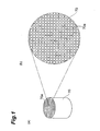
- the green honeycomb molded body 70 shown in Fig. 1 is obtained by extrusion molding a raw material composition.
- the green honeycomb molded body 70 is a circular column having a plurality of through-holes 70a arranged in a substantially parallel manner.
- the cross-sectional shapes of the through-holes 70a are square, as shown in Fig. 1(b) .
- the plurality of through-holes 70a have a square arrangement for the green honeycomb molded body 70, i.e. the central axes of the through-holes 70a are disposed so that they are positioned at the apexes of squares.
- the square shapes of the cross-sections of the through-holes 70a may have sizes with sides of 0.8 to 2.5 mm, for example.
- a honeycomb structure is produced by firing the green honeycomb molded body 70 at a prescribed temperature.
- the length of the through-holes 70a of the green honeycomb molded body 70 in the direction of their extension there are no particular restrictions on the length of the through-holes 70a of the green honeycomb molded body 70 in the direction of their extension, and it may be 40 to 350 mm, for example.
- the outer diameter of the green honeycomb molded body 70 there are also no particular restrictions on the outer diameter of the green honeycomb molded body 70, and it may be 100 to 320 mm, for example.
- the raw material composition forming the green honeycomb molded body 70 includes an inorganic compound source powder as the ceramic starting material, an organic binder such as methyl cellulose, and additives that are added as necessary.
- preferred ceramic materials include oxides such as alumina, silica, mullite, cordierite, glass and aluminum titanate, or silicon carbide, silicon nitride and the like.
- Aluminum titanate may further include magnesium and/or silicon.
- the inorganic compound source powder may include an aluminum source powder such as ⁇ -alumina powder, and a titanium source powder such as anatase or rutile titania powder, and if necessary also a magnesium source powder such as magnesia powder or magnesia spinel powder, and/or a silicon source powder such as silicon oxide powder or glass frit.
- an aluminum source powder such as ⁇ -alumina powder
- a titanium source powder such as anatase or rutile titania powder
- magnesium source powder such as magnesia powder or magnesia spinel powder
- silicon source powder such as silicon oxide powder or glass frit.
- Organic binders include celluloses such as methyl cellulose, carboxylmethyl cellulose, hydroxyalkylmethyl celluloses and sodium carboxylmethyl cellulose; alcohols such as polyvinyl alcohol; and ligninsulfonic acid salts.
- additives examples include pore-forming agents, lubricants, plasticizers, dispersing agents and solvents.
- Pore-forming agents include carbon materials such as graphite; resins such as polyethylene, polypropylene and polymethyl methacrylate; plant materials such as starch, nut shells, walnut shells and corn; ice; and dry ice.
- Lubricants and plasticizers include alcohols such as glycerin; higher fatty acids such as caprylic acid, lauric acid, palmitic acid, arachidic acid, oleic acid and stearic acid; stearic acid metal salts such as Al stearate; and polyoxyalkylenealkyl ethers (POAAE).
- alcohols such as glycerin
- higher fatty acids such as caprylic acid, lauric acid, palmitic acid, arachidic acid, oleic acid and stearic acid
- stearic acid metal salts such as Al stearate
- POAAE polyoxyalkylenealkyl ethers
- dispersing agents examples include inorganic acids such as nitric acid, hydrochloric acid and sulfuric acid; organic acids such as oxalic acid, citric acid, acetic acid, malic acid and lactic acid; alcohols such as methanol, ethanol and propanol; and surfactants such as ammonium polycarboxylate and polyoxyalkylenealkyl ethers.
- solvents examples include alcohols such as methanol, ethanol, butanol and propanol; glycols such as propylene glycol, polypropylene glycol and ethylene glycol; and water.
- the extrusion-molding device 10 shown in Fig. 2 is for production of a green honeycomb molded body 70 from a powdered or paste raw material composition.
- the extrusion-molding device 10 comprises a screw 2A provided in the upper level of a housing 1, and a screw 2B provided in the lower level.
- the screws 2A, 2B knead a raw material composition supplied through an entry port 1a, while transporting it through a flow passage 1b toward the downstream.
- a vacuum chamber 3 Between the screws 2A, 2B there is provided a vacuum chamber 3, with pressure reduction in the vacuum chamber 3 allowing deaerating treatment of the raw material composition.
- the raw material composition in the vacuum chamber 3 is introduced into the lower level screw 2B by a roller 3a.
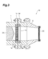
- the extrusion-molding device 10 further comprises a fragmenting board 5 provided downstream of the screw 2B, a die 20 through which the molded body 70A composed of the raw material composition is extruded, and a resistance tube 9 connecting the flow passage 1b and the die 20.
- the resistance tube 9 has a tapered interior flow passage, with the cross-sectional area of the flow passage gradually decreasing from the upstream toward the downstream.
- the resistance tube 9 may have an enlarged section in which the flow passage cross-section increases from the upstream toward the downstream.
- a support stage 15 for support of the molded body 70A is situated next to the extrusion-molding device 10.
- the die 20 shown in Fig. 4 has slits corresponding to the shape of the cell structure of the green honeycomb molded body 70.
- the die 20 comprises a die main body 21 with raw material-supply holes 21a and slits 21b, a cover ring 22, a spacer 24 and a holder 28.
- the die main body 21 has a side S1 situated on the upstream end and a side S2 situated on the downstream end when mounted on the extrusion-molding device.
- a plurality of raw material supply holes 21a are formed on the side S1 and lattice-like slits 21b connected to the raw material supply hole 21a are formed on the side S2.
- the raw material composition supplied from the side S1 side of the die main body 21 reaches the side S2 side through the raw material supply holes 21a and the slits 21 b, and is extruded as a cell structure with a square arrangement.
- the opening width D of the slits of the die 20 is preferably 0.05 to 0.5 mm, more preferably 0.1 to 0.5 mm and even more preferably 0.12 to 0.38 mm, although this will depend on the viscosity of the raw material composition (see Fig. 4 ).
- Fig. 4 shows a die main body 21 with an overall flat discharge surface (side S2), the center section of the discharge surface of the die main body may be protruding, or a recess may be formed. In such cases, a level difference will be created between the center section and perimeter (the region containing the spacer, etc.) of the discharge surface.
- the cover ring 22 is disposed covering the perimeter of the side S2 of the die main body 21.
- the cover ring 22 has an opening with an inner diameter corresponding to the outer diameter of the green honeycomb molded body 70.
- a cover ring 22 with a prescribed inner diameter it is possible to obtain a green honeycomb molded body 70 with the prescribed outer diameter, regardless of the outer shape of the die main body 21.
- the spacer 24 is disposed between the die main body 21 and the cover ring 22.
- the spacer 24 is made of a sheet-like material with a thickness of about 0.3 to 1.0 mm. Specific examples for the material of the spacer 24 include metals such as copper, paper, resins and the like.
- the spacer 24 has an opening that is larger around the edges than the opening of the cover ring 22.
- the holder 28 serves to anchor the cover ring 22 and spacer to the die main body 21.
- the fragmenting board 5 serves to remove extraneous material from the raw material composition while fragmenting the aggregated masses in the raw material composition, before the raw material composition is introduced into the die 20.
- the fragmenting board 5 is provided in a detachable manner with respect to the housing 1, and it is disposed between the screw 2B and the die 20.
- flanges 1c, 1d are tightened with a bolt and nut, anchoring the fragmenting board 5 to the housing 1 together with an annular jig 5a.
- the jig 5a serves to adjust the discharge shape (inner diameter), and is disposed covering the perimeter of the downstream end side F2 of the fragmenting board 5.
- the fragmenting board 5 has through-passages 6 through which a raw material composition passes from the upstream end side F1 to the downstream end side F2, the through-passages 6 being formed of the upstream channels 6A and the downstream channels 6B.
- the upstream channels 6A are composed of a plurality of flow passages 6a extending downstream essentially straight from the upstream end side F1. Each flow passage 6a has a substantially circular flow passage cross-sectional shape.
- the downstream channels 6B are formed of perpendicularly crossing slits S.
- the slits S have a pattern identical or similar to the slits 21b of the die main body 21.
- the value of the open area ratio at the downstream end of the fragmenting board 5 is preferably equal to or greater than the value of the open area ratio at the downstream end of the die 20.
- the open area ratios at the downstream ends of the fragmenting board 5 and die 20 are calculated by the following formula (1).
- X 2 ⁇ b / c - b / c 2
- b represents the slit opening width
- c represents the slit pattern pitch.
- B in Fig. 6 corresponds to the opening width (b) of the slits S of the fragmenting board 5
- C corresponds to the slit pattern pitch (c) of the fragmenting board 5.
- the ratio (A/B) between the thickness A at the section of the fragmenting board 5 where the slits S are formed and the opening width B of the slits S is preferably 1 to 10 and more preferably 1 to 5 (see Fig. 7 ). If the value of A/B is less than 1 the dispersion effect on aggregated masses will be inadequate and the aggregated masses will tend to reaggregate after passing through the fragmenting board 5, tending to produce defects in the green molded body. If the value of A/B exceeds 10, on the other hand, pressure loss due to the fragmenting board 5 will tend to become excessively high.
- the ratio (C/B) between the pitch C of the pattern of the slits S of the fragmenting board 5 and the opening width B of the slits S on the downstream end side F2 of the fragmenting board 5 is preferably 1 to 10 and more preferably 1 to 5 (see Fig. 7 ). If the value of C/B is less than 1 the dispersion effect on aggregated masses will be inadequate and the aggregated masses will tend to reaggregate after passing through the fragmenting board 5, tending to produce defects in the green molded body. If the value of C/B exceeds 10, on the other hand, pressure loss due to the fragmenting board 5 will tend to become excessively high.
- the ratio (B/D) between the opening width B of the slits S of the fragmenting board 5 and the opening width D of the slits S of the die 20 is preferably 0.2 to 1.5 and more preferably 0.3 to 1.0 (see Fig. 4 and Fig. 6(b) ). If the value of B/D is less than 0.2, pressure loss by the fragmenting board 5 will tend to become excessively high. If the value of B/D is greater than 1.5, on the other hand, the upstream end side S1 of the die 20 will tend to become obstructed by aggregated masses that have passed through the fragmenting board 5, and defects will tend to be produced in the green honeycomb molded body 70 as a result.
- the fragmenting board 5 is preferably a structure that undergoes essentially no strain even when under pressure from the upstream end.
- the material of the fragmenting board 5 is preferably carbon steel, for example. Examples of preferred materials other than carbon steel include special steel containing nickel, chromium, tungsten or the like.
- the thickness of the fragmenting board 5 is preferably 10 to 100 mm, from the viewpoint of ensuring sufficient strength. If the downstream channels 6B are slits S, it will be possible to achieve satisfactory degrees of high open area ratio and high mechanical strength.
- the fragmenting board 5 exhibits a high rectifying effect on the raw material composition and can rectify the flow of the raw material composition before the raw material composition is supplied to the die 20, thereby allowing efficient production of a green honeycomb molded body with high dimensional precision.
- a method of producing the green honeycomb molded body 70 using the extrusion-molding device 10 will now be described.
- a raw material composition is introduced into the flow passage 1b through the entry port 1a.
- the kneaded blend passes through the through-passages 6 of the fragmenting board 5, thus homogenizing the flow rate distribution, and it is then introduced into the die 20.
- the linear speed of the raw material composition at the downstream end of the die 20 is preferably about 10 to 150 cm/min.
- the raw material composition with homogenized flow rate distribution is extruded from the die 20 and the molded body 70A is collected on the support stage 15.
- the molded body 70A is cut to a prescribed length to obtain a green honeycomb molded body 70.
- downstream channels 6B of the fragmenting board 5 were composed of slits S in a pattern similar (identical or nearly identical) to the die 20, but the downstream channels may instead be composed of a plurality of independent slits.
- the downstream channels 7B of the fragmenting board 7 shown in Fig. 8 are composed of a plurality of cross-shaped slits 7b each penetrating the plurality of flow passages 7a forming the upstream channels 7A.
- the value of the open area ratio at the downstream end of the fragmenting board 7 is preferably equal to or greater than the value of the open area ratio at the downstream end of the die 20.
- the open area ratio at the downstream end of the fragmenting board 7 is calculated by formula (2) above.
- B' in Fig. 8 corresponds to the opening width (b') of the slits S of the fragmenting board 7
- C' corresponds to the slit pattern pitch (c') of the fragmenting board 5
- E' corresponds to the distance (e') between the edges of the adjacent slits.
- X ⁇ 2 ⁇ b ⁇ / c ⁇ - b ⁇ / c ⁇ 2 - 2 ⁇ b ⁇ e ⁇
- the ratio (A/B') between the thickness A at the section of the fragmenting board 7 where the slits S are formed and the opening width B' of the slits S is preferably 1 to 10 and more preferably 1 to 5 (see Fig. 8 ). If the value of A/B' is less than 1 the dispersion effect on aggregated masses will be inadequate and the aggregated masses will tend to reaggregate after passing through the fragmenting board 5, tending to produce defects in the green molded body. If the value of A/B' exceeds 10, on the other hand, pressure loss due to the fragmenting board 7 will tend to become excessively high.
- the ratio (C'/B') between the pitch C' of the pattern of the slits S of the fragmenting board 7 and the opening width B' of the slits S on the downstream end side F2 of the fragmenting board 7 is preferably 1 to 10 and more preferably 1 to 5 (see Fig. 8 ). If the value of C'/B' is less than 1 the dispersion effect on aggregated masses will be inadequate and the aggregated masses will tend to reaggregate after passing through the fragmenting board 7, tending to produce defects in the green molded body. If the value of C'/B' exceeds 10, on the other hand, pressure loss due to the fragmenting board 7 will tend to become excessively high.
- the ratio (B'/D) between the opening width B' of the slits S of the fragmenting board 7 and the opening width D of the slits S of the die 20 is preferably 0.2 to 1.5 and more preferably 0.3 to 1.0 (see Fig. 4 and Fig. 8 ). If the value of B'/D is less than 0.2, pressure loss due to the fragmenting board 7 will tend to become excessively high. If the value of B'/D is greater than 1.5, on the other hand, the upstream end side S1 of the die 20 will tend to become obstructed by aggregated masses that have passed through the fragmenting board 7, and defects will tend to be produced in the green honeycomb molded body 70 as a result.
- the slit shapes are not limited to being cross-shaped and do not necessarily need to be slits.
- the shape and structure of the molded body are not limited to those shown.
- the outer shape of the green honeycomb molded body 70 may be rectangular columnar, such as square columnar, or elliptic cylindrical, for example.
- the arrangement of the through-holes 70a does not need to be a square arrangement, and may instead be a substantially triangular arrangement or substantially hexagonal arrangement, for example.
- the shapes of the through-holes 70a do not need to be square, and may instead be substantially triangular, substantially hexagonal, substantially octagonal or substantially circular, or a combination of the foregoing.
- Combinations of multiple shapes include combinations of regular hexagons and asymmetrical hexagons (see Fig. 9 ), and combinations of quadrilaterals and octagons (octosquares).
- the green honeycomb molded body 80 shown in Fig. 9 has a plurality of through-holes 81a, 81b with different cross-sectional shapes.
- the plurality of through-holes 81a, 81b are partitioned by partitions 82 extending substantially parallel to the central axis of the green honeycomb molded body 80.
- the through-holes 81a have cross-sectional shapes that are regular hexagonal.
- the through-holes 81b on the other hand, have cross-sectional shapes that are flattened hexagonal, and they are disposed surrounding the through-holes 81 a.
- this embodiment was described as a case where the cell structure of the green honeycomb molded body 70 and the pattern of the slits S of the fragmenting board 5 were both square configurations, but there is no particular need for these patterns to match.
- the pattern of the slits S of the fragmenting board 5 may be appropriately selected as substantially triangular or substantially hexagonal, for example.
- a fragmenting board having a pattern identical or similar to the die for the green honeycomb molded body 80 may be employed, or the fragmenting board 5 or fragmenting board 7 described above may be employed.
- the upstream end side F1 of the fragmenting board may be chamfered, for example, and the inlets of the upstream channels tapered, or the upstream channels may have an alternating configuration so as to allow the diameters of the upstream channels to be widened (a configuration with alternatingly selected slit intersections).
- a fragmenting board (made of tool steel) was prepared having the same construction as the fragmenting boards shown in Figs. 6 and 7 , and was mounted upstream a die (see Fig. 3 ).
- the die used was one allowing production of a green honeycomb molded body of the type shown in Fig. 9 .
- the ratio (B/D) between the slit opening width B of the fragmenting board and the slit opening width D of the die was 1.2.
- the fragmenting board was removed from the extrusion-molding device and examined, and no damage was found.
- the perpendicularity of the green honeycomb molded body was measured.
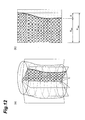
- the definition of perpendicularity and method for measuring it are as follows. As shown in Fig. 12 , the green honeycomb molded body is erected vertical on a horizontal plane. With imaginary planes considered to be formed by imaginary lines extending in a radial fashion centered around the center of gravity on the bottom edge surface of the green honeycomb molded body (point O in Fig. 12(a) ), and moving upward in a vertical line, the differences between the radii of the contour lines of the green honeycomb molded body cut by the imaginary planes are calculated (X in Fig. 12(b) ). The values of X are calculated for each of the imaginary planes, and the maximum is defined as the perpendicularity.
- strainer stainless steel
- breaker plate stainless steel
- the fragmenting board was removed from the extrusion-molding device and examined, and several locations of damage were found in the strainer wire mesh.
- the average value of the perpendicularity measured for 10 molded bodies in the same manner as the examples was 1.5 mm (standard deviation: 0.388 mm).
- 1 Housing, 1b: flow passage, 2B: screw, 5, 7: fragmenting boards, 6: through-passage, 6A, 7A: upstream channels, 6B, 7B: downstream channels, 6a, 7a: flow passages (through-passages), S, 7b: fragmenting board slits, 9: resistance tube, 10: extrusion-molding device, 20: die, 21b: die slit, 70, 80: green honeycomb molded bodies, F1: fragmenting board upstream end side, F2: fragmenting board downstream end side.
Landscapes
- Engineering & Computer Science (AREA)
- Mechanical Engineering (AREA)
- Chemical & Material Sciences (AREA)
- Ceramic Engineering (AREA)
- Manufacturing & Machinery (AREA)
- Materials Engineering (AREA)
- Structural Engineering (AREA)
- Organic Chemistry (AREA)
- Press-Shaping Or Shaping Using Conveyers (AREA)
Abstract
Description
- The present invention relates to a technique for producing a molded body, and more specifically, it relates to a technique for producing a green honeycomb molded body.
- Honeycomb filter structures for Diesel Particulate Filters are widely known in the conventional art. Such honeycomb filter structures have a structure wherein some of the through-holes of a honeycomb structure having a plurality of through-holes have one of their sides plugged with a plugging material, while the other sides of the remaining through-holes are likewise plugged with a plugging material. In
Patent literatures 1 and 2 there are disclosed a die and extrusion-molding device to be used for production of a green honeycomb molded body. -
- [PTL 1] Japanese Unexamined Patent Application Publication No.
61-5915 - [PTL 2] Japanese Patent No.
4099896 - Filtration treatment of raw material compositions is known in the conventional art for prior removal of coarse grains and extraneous material in paste raw material compositions, before supply of such raw material compositions to a die. For example, Patent literature 2 describes an extrusion-molding device having a screen (filtering net) mounted at the upstream of a molding die (see
Fig. 1 of Patent literature 2). - When a screen with a suitable mesh size is used for filtration of a raw material composition, it is possible to remove relatively hard extraneous materials (such as metal fragments) included in the raw material composition and reduce defects caused thereby in the molded body. However, it is not possible to adequately remove loosely bound aggregated masses that are able to pass through the conventional screens mounted on extrusion-molding devices, and therefore defects caused thereby cannot be satisfactorily reduced. Conventional screens also have room for improvement in terms of strength, because it has been necessary to halt operation of the device each time for screen replacement when the screen tears due to the extraneous material.
- It is an object of the present invention to provide an extrusion-molding device that can satisfactorily reduce defects in the partitions forming the cell structure and in the outer peripheral walls when a green honeycomb molded body is produced, as well as a method for producing a molded body using the same.
- The extrusion-molding device of the invention serves to produce a green honeycomb molded body with a cell structure, and the device includes: a housing with a flow passage for transporting a paste raw material composition; a screw provided upstream of the flow passage for kneading the raw material composition and transporting it downstream; a die provided downstream of the flow passage and having slits corresponding to the shape of the cell structure of the green honeycomb molded body; a resistance tube for connecting the flow passage and the die; and a fragmenting board provided between the screw and the die, having through-passages through which the raw material composition passes from an upstream end side to a downstream end side thereof, wherein the through-passages comprise upstream channels composed of a plurality of flow passages extending downstream from the upstream end side of the fragmenting board; and downstream channels extending up to the downstream end side of the fragmenting board and having flow passage cross-sectional shapes different from those of the upstream channels.
- According to the invention the flow passage cross-sectional shapes of the upstream channels and the downstream channels forming the through-passages of the fragmenting board are different from each other, thereby creating a more complex flow of the raw material composition in the through-passages. The raw material composition is thus fragmented as it passes through the through-passages of the fragmenting board, preventing large aggregated masses from reaching the die in that state and making it possible to satisfactorily reduce defects in the partitions forming the cell structure and in the outer peripheral wall. In addition, since the fragmenting board can be given higher strength than the screen, it is possible to reduce the frequency of maintenance and increase productivity.
- According to the invention, it is possible to employ a construction similar to die slits as the construction of the downstream channels of the fragmenting board. Specifically, the upstream channels may be composed of a plurality of flow passages extending downstream essentially straight from the upstream end side of the fragmenting while the downstream channels may be composed of slits having a pattern identical or similar to die slits. By employing such a construction, aggregated masses can be fragmented to a high degree by the downstream channels (slits) of the fragmenting board, thereby obtaining a high rectifying effect for the raw material composition. By adjusting the flow (evening the flow rate distribution) of the raw material composition before the raw material composition is supplied to the die, it is possible to efficiently produce a green honeycomb molded body with high dimensional precision.
- Incidentally, an "identical or similar pattern" between the fragmenting board slits and die slits is determined primarily based on the pitch of the slits. For example, when both the die and fragmenting board have lattice-like slits, both have an identical pattern if the slit pitch is the same, even if the opening widths of the slits differ, while both are considered to have a similar pattern in case where the opening widths of the slits of both are identical and only the slit pitch differs.
- When the downstream channels of the fragmenting board are similar to the slits of the die, the ratio (A/B) between the thickness A of the section where the slits are formed in the fragmenting board and the opening width B of the slits on the downstream end side of the fragmenting board, is preferably between 1 and 10, and the ratio (C/B) between the pitch C in the pattern of the slits of the fragmenting board and the opening width B of the slits on the downstream end side of the fragmenting board is preferably between 1 and 10 (see
Fig. 7 ). - According to the invention, the construction of the downstream channels of the fragmenting board is not limited to being a construction similar to die slits (a construction with connected slits), and may instead be a construction with a plurality of unconnected slits. That is, the upstream channels may be composed of a plurality of flow passages extending downstream essentially straight from the upstream end side of the fragmenting board while the downstream channels may be composed of a plurality of slits each connected to the plurality of flow passages. Even when this type of construction is employed, the aggregated masses can be fragmented to a high degree by the downstream end flow passage (the plurality of slits) of the fragmenting board, thereby obtaining a high rectifying effect for the raw material composition. By adjusting the flow (evening the flow rate distribution) of the raw material composition before the raw material composition is introduced into the die, it is possible to efficiently produce a molded body with high dimensional precision.
- According to the invention, the ratio (C'B') between the spacing C' between the centers of the through-passages on the downstream end side of the fragmenting board and the aperture dimension B' of the through-passages on the downstream end side of the fragmenting board is preferably between 1 and 10 (see
Fig. 6(b) andFig. 8 ). - According to the invention, the ratio (B'/D) between the aperture dimension B' of the through-passages on the downstream end side of the fragmenting board and the opening width D of the die slits is preferably between 0.2 and 1.5 (see
Fig. 4 ,Fig. 6(b) andFig. 8 ). - The invention provides a method for producing a green honeycomb molded body using the extrusion-molding device described above. According to the method of the invention, the action of the fragmenting board can satisfactorily reduce defects in the partitions forming the cell structure and in the outer peripheral walls.
- According to the invention it is possible to satisfactorily reduce defects in the partitions forming the cell structure and in the outer peripheral walls when a green honeycomb molded body is produced.
-
-
Fig. 1(a) is a perspective view showing one example of a green honeycomb molded body, andFig. 1(b) is a partial magnified view of a green honeycomb molded body. -
Fig. 2 is a simplified cross-sectional view showing an embodiment of an extrusion-molding device according to the invention. -
Fig. 3 is a partial cross-sectional view schematically showing the internal structure of the extrusion-molding device ofFig. 2 . -
Fig. 4 is a partial end view showing an example of the construction of a die. -
Fig. 5 is a plan view showing an example of the upstream end side of a fragmenting board. -
Fig. 6(a) is a plan view showing an example of the downstream end side of a fragmenting board, andFig. 6(b) is a partial magnified view of the downstream end side shown inFig. 6(a) . -
Fig. 7 is a partial end view schematically showing the internal structure of the fragmenting board ofFig. 5 . -
Fig. 8 is a partial magnified view of the downstream end side of a fragmenting board according to another embodiment. -
Fig. 9 is a diagram showing another example of a green honeycomb molded body. -
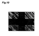
Fig. 10 is a photograph showing extraneous material trapped in a fragmenting board. -
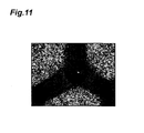
Fig. 11 is a photograph showing extraneous material after it has reached a die. -
Fig. 12 is a diagram illustrating a method of measuring the perpendicularity of a green honeycomb molded body. - Preferred embodiments of the invention will now be explained in detail, with reference to the accompanying drawings. A green honeycomb molded body for a honeycomb structure will be explained first, before explanation of the extrusion-molding device of the invention.
- The green honeycomb molded
body 70 shown inFig. 1 is obtained by extrusion molding a raw material composition. As shown inFig. 1(a) , the green honeycomb moldedbody 70 is a circular column having a plurality of through-holes 70a arranged in a substantially parallel manner. The cross-sectional shapes of the through-holes 70a are square, as shown inFig. 1(b) . As viewed from an end face, the plurality of through-holes 70a have a square arrangement for the green honeycomb moldedbody 70, i.e. the central axes of the through-holes 70a are disposed so that they are positioned at the apexes of squares. The square shapes of the cross-sections of the through-holes 70a may have sizes with sides of 0.8 to 2.5 mm, for example. A honeycomb structure is produced by firing the green honeycomb moldedbody 70 at a prescribed temperature. - There are no particular restrictions on the length of the through-
holes 70a of the green honeycomb moldedbody 70 in the direction of their extension, and it may be 40 to 350 mm, for example. There are also no particular restrictions on the outer diameter of the green honeycomb moldedbody 70, and it may be 100 to 320 mm, for example. - There are no particular restrictions on the raw material composition forming the green honeycomb molded
body 70, but for production of a honeycomb structure for a Diesel Particulate Filter, it includes an inorganic compound source powder as the ceramic starting material, an organic binder such as methyl cellulose, and additives that are added as necessary. From the viewpoint of high-temperature resistance of the honeycomb structure, preferred ceramic materials include oxides such as alumina, silica, mullite, cordierite, glass and aluminum titanate, or silicon carbide, silicon nitride and the like. Aluminum titanate may further include magnesium and/or silicon. - For production of an aluminum titanate green honeycomb molded body, for example, the inorganic compound source powder may include an aluminum source powder such as α-alumina powder, and a titanium source powder such as anatase or rutile titania powder, and if necessary also a magnesium source powder such as magnesia powder or magnesia spinel powder, and/or a silicon source powder such as silicon oxide powder or glass frit.
- Organic binders include celluloses such as methyl cellulose, carboxylmethyl cellulose, hydroxyalkylmethyl celluloses and sodium carboxylmethyl cellulose; alcohols such as polyvinyl alcohol; and ligninsulfonic acid salts.
- Examples of additives include pore-forming agents, lubricants, plasticizers, dispersing agents and solvents.
- Pore-forming agents include carbon materials such as graphite; resins such as polyethylene, polypropylene and polymethyl methacrylate; plant materials such as starch, nut shells, walnut shells and corn; ice; and dry ice.
- Lubricants and plasticizers include alcohols such as glycerin; higher fatty acids such as caprylic acid, lauric acid, palmitic acid, arachidic acid, oleic acid and stearic acid; stearic acid metal salts such as Al stearate; and polyoxyalkylenealkyl ethers (POAAE).
- Examples of dispersing agents include inorganic acids such as nitric acid, hydrochloric acid and sulfuric acid; organic acids such as oxalic acid, citric acid, acetic acid, malic acid and lactic acid; alcohols such as methanol, ethanol and propanol; and surfactants such as ammonium polycarboxylate and polyoxyalkylenealkyl ethers.
- Examples of solvents include alcohols such as methanol, ethanol, butanol and propanol; glycols such as propylene glycol, polypropylene glycol and ethylene glycol; and water.
- Embodiments of the extrusion-molding device of the invention will now be explained. The extrusion-
molding device 10 shown inFig. 2 is for production of a green honeycomb moldedbody 70 from a powdered or paste raw material composition. - The extrusion-
molding device 10 comprises ascrew 2A provided in the upper level of ahousing 1, and ascrew 2B provided in the lower level. Thescrews entry port 1a, while transporting it through aflow passage 1b toward the downstream. Between thescrews vacuum chamber 3, with pressure reduction in thevacuum chamber 3 allowing deaerating treatment of the raw material composition. The raw material composition in thevacuum chamber 3 is introduced into thelower level screw 2B by aroller 3a. - As shown in
Fig. 3 , the extrusion-molding device 10 further comprises a fragmentingboard 5 provided downstream of thescrew 2B, a die 20 through which the moldedbody 70A composed of the raw material composition is extruded, and aresistance tube 9 connecting theflow passage 1b and thedie 20. Theresistance tube 9 has a tapered interior flow passage, with the cross-sectional area of the flow passage gradually decreasing from the upstream toward the downstream. For production of a moldedbody 70A having a larger diameter than the diameter of thescrew 2B, theresistance tube 9 may have an enlarged section in which the flow passage cross-section increases from the upstream toward the downstream. In order to prevent deformation of the moldedbody 70A that has been extruded from thedie 20, asupport stage 15 for support of the moldedbody 70A is situated next to the extrusion-molding device 10. - The die 20 shown in
Fig. 4 has slits corresponding to the shape of the cell structure of the green honeycomb moldedbody 70. Thedie 20 comprises a diemain body 21 with raw material-supply holes 21a and slits 21b, acover ring 22, aspacer 24 and aholder 28. - The die
main body 21 has a side S1 situated on the upstream end and a side S2 situated on the downstream end when mounted on the extrusion-molding device. A plurality of rawmaterial supply holes 21a are formed on the side S1 and lattice-like slits 21b connected to the rawmaterial supply hole 21a are formed on the side S2. The raw material composition supplied from the side S1 side of the diemain body 21 reaches the side S2 side through the rawmaterial supply holes 21a and theslits 21 b, and is extruded as a cell structure with a square arrangement. The opening width D of the slits of the die 20 is preferably 0.05 to 0.5 mm, more preferably 0.1 to 0.5 mm and even more preferably 0.12 to 0.38 mm, although this will depend on the viscosity of the raw material composition (seeFig. 4 ). Incidentally, althoughFig. 4 shows a diemain body 21 with an overall flat discharge surface (side S2), the center section of the discharge surface of the die main body may be protruding, or a recess may be formed. In such cases, a level difference will be created between the center section and perimeter (the region containing the spacer, etc.) of the discharge surface. - The
cover ring 22 is disposed covering the perimeter of the side S2 of the diemain body 21. Thecover ring 22 has an opening with an inner diameter corresponding to the outer diameter of the green honeycomb moldedbody 70. In other words, by using acover ring 22 with a prescribed inner diameter it is possible to obtain a green honeycomb moldedbody 70 with the prescribed outer diameter, regardless of the outer shape of the diemain body 21. - The
spacer 24 is disposed between the diemain body 21 and thecover ring 22. Thespacer 24 is made of a sheet-like material with a thickness of about 0.3 to 1.0 mm. Specific examples for the material of thespacer 24 include metals such as copper, paper, resins and the like. Thespacer 24 has an opening that is larger around the edges than the opening of thecover ring 22. Situating thespacer 24 having such a construction between the diemain body 21 and thecover ring 22 creates a gap between them. The raw material composition that has passed through the gap becomes the outer peripheral skin (or outer peripheral wall) of the green honeycomb moldedbody 70. A cover ring having a gap formed by a spacer may also be used, in which case no spacer will be necessary. When a moldedbody 70A having a specific outer diameter and outer shape is to be specially produced, a die without a spacer and cover ring may be used. - The
holder 28 serves to anchor thecover ring 22 and spacer to the diemain body 21. - The fragmenting
board 5 serves to remove extraneous material from the raw material composition while fragmenting the aggregated masses in the raw material composition, before the raw material composition is introduced into thedie 20. The fragmentingboard 5 is provided in a detachable manner with respect to thehousing 1, and it is disposed between thescrew 2B and thedie 20. For example,flanges board 5 to thehousing 1 together with anannular jig 5a. Thejig 5a serves to adjust the discharge shape (inner diameter), and is disposed covering the perimeter of the downstream end side F2 of the fragmentingboard 5. - As shown in
Figs. 5 to 7 , the fragmentingboard 5 has through-passages 6 through which a raw material composition passes from the upstream end side F1 to the downstream end side F2, the through-passages 6 being formed of theupstream channels 6A and thedownstream channels 6B. Theupstream channels 6A are composed of a plurality offlow passages 6a extending downstream essentially straight from the upstream end side F1. Eachflow passage 6a has a substantially circular flow passage cross-sectional shape. Thedownstream channels 6B, on the other hand, are formed of perpendicularly crossing slits S. The slits S have a pattern identical or similar to theslits 21b of the diemain body 21. - In order to keep pressure loss due to the fragmenting
board 5 from exceeding pressure loss due to thedie 20, the value of the open area ratio at the downstream end of the fragmentingboard 5 is preferably equal to or greater than the value of the open area ratio at the downstream end of thedie 20. The open area ratios at the downstream ends of the fragmentingboard 5 and die 20 are calculated by the following formula (1).
In the formula, b represents the slit opening width, and c represents the slit pattern pitch. B inFig. 6 corresponds to the opening width (b) of the slits S of the fragmentingboard 5, and C corresponds to the slit pattern pitch (c) of the fragmentingboard 5. - The ratio (A/B) between the thickness A at the section of the fragmenting
board 5 where the slits S are formed and the opening width B of the slits S is preferably 1 to 10 and more preferably 1 to 5 (seeFig. 7 ). If the value of A/B is less than 1 the dispersion effect on aggregated masses will be inadequate and the aggregated masses will tend to reaggregate after passing through the fragmentingboard 5, tending to produce defects in the green molded body. If the value of A/B exceeds 10, on the other hand, pressure loss due to the fragmentingboard 5 will tend to become excessively high. - The ratio (C/B) between the pitch C of the pattern of the slits S of the fragmenting
board 5 and the opening width B of the slits S on the downstream end side F2 of the fragmentingboard 5 is preferably 1 to 10 and more preferably 1 to 5 (seeFig. 7 ). If the value of C/B is less than 1 the dispersion effect on aggregated masses will be inadequate and the aggregated masses will tend to reaggregate after passing through the fragmentingboard 5, tending to produce defects in the green molded body. If the value of C/B exceeds 10, on the other hand, pressure loss due to the fragmentingboard 5 will tend to become excessively high. - The ratio (B/D) between the opening width B of the slits S of the fragmenting
board 5 and the opening width D of the slits S of the die 20 is preferably 0.2 to 1.5 and more preferably 0.3 to 1.0 (seeFig. 4 andFig. 6(b) ). If the value of B/D is less than 0.2, pressure loss by the fragmentingboard 5 will tend to become excessively high. If the value of B/D is greater than 1.5, on the other hand, the upstream end side S1 of the die 20 will tend to become obstructed by aggregated masses that have passed through the fragmentingboard 5, and defects will tend to be produced in the green honeycomb moldedbody 70 as a result. - The fragmenting
board 5 is preferably a structure that undergoes essentially no strain even when under pressure from the upstream end. From this viewpoint, the material of the fragmentingboard 5 is preferably carbon steel, for example. Examples of preferred materials other than carbon steel include special steel containing nickel, chromium, tungsten or the like. The thickness of the fragmentingboard 5 is preferably 10 to 100 mm, from the viewpoint of ensuring sufficient strength. If thedownstream channels 6B are slits S, it will be possible to achieve satisfactory degrees of high open area ratio and high mechanical strength. - According to this embodiment, it is possible to create a more complex flow of the raw material composition inside the through-passages 6 of the fragmenting
board 5. The raw material composition is thus fragmented as it passes through the through-passages 6 of the fragmentingboard 5, preventing large aggregated masses from reaching the die 20 in that state and making it possible to satisfactorily reduce defects in the partitions forming the cell structure and in the outer peripheral wall. In addition, the fragmentingboard 5 exhibits a high rectifying effect on the raw material composition and can rectify the flow of the raw material composition before the raw material composition is supplied to thedie 20, thereby allowing efficient production of a green honeycomb molded body with high dimensional precision. - A method of producing the green honeycomb molded
body 70 using the extrusion-molding device 10 will now be described. First, a raw material composition is introduced into theflow passage 1b through theentry port 1a. By rotating thescrews board 5, thus homogenizing the flow rate distribution, and it is then introduced into thedie 20. The linear speed of the raw material composition at the downstream end of the die 20 is preferably about 10 to 150 cm/min. - The raw material composition with homogenized flow rate distribution is extruded from the
die 20 and the moldedbody 70A is collected on thesupport stage 15. The moldedbody 70A is cut to a prescribed length to obtain a green honeycomb moldedbody 70. - The above detailed explanation of a preferred embodiment of the invention is not intended to restrict the scope of the invention to this embodiment. For example, according to this embodiment the
downstream channels 6B of the fragmentingboard 5 were composed of slits S in a pattern similar (identical or nearly identical) to thedie 20, but the downstream channels may instead be composed of a plurality of independent slits. For example, thedownstream channels 7B of the fragmentingboard 7 shown inFig. 8 are composed of a plurality ofcross-shaped slits 7b each penetrating the plurality offlow passages 7a forming theupstream channels 7A. - In order to keep pressure loss due to the fragmenting
board 7 from exceeding pressure loss due to thedie 20, the value of the open area ratio at the downstream end of the fragmentingboard 7 is preferably equal to or greater than the value of the open area ratio at the downstream end of thedie 20. The open area ratio at the downstream end of the fragmentingboard 7 is calculated by formula (2) above. B' inFig. 8 corresponds to the opening width (b') of the slits S of the fragmentingboard 7, C' corresponds to the slit pattern pitch (c') of the fragmentingboard 5, and E' corresponds to the distance (e') between the edges of the adjacent slits.
- The ratio (A/B') between the thickness A at the section of the fragmenting
board 7 where the slits S are formed and the opening width B' of the slits S is preferably 1 to 10 and more preferably 1 to 5 (seeFig. 8 ). If the value of A/B' is less than 1 the dispersion effect on aggregated masses will be inadequate and the aggregated masses will tend to reaggregate after passing through the fragmentingboard 5, tending to produce defects in the green molded body. If the value of A/B' exceeds 10, on the other hand, pressure loss due to the fragmentingboard 7 will tend to become excessively high. - The ratio (C'/B') between the pitch C' of the pattern of the slits S of the fragmenting
board 7 and the opening width B' of the slits S on the downstream end side F2 of the fragmentingboard 7 is preferably 1 to 10 and more preferably 1 to 5 (seeFig. 8 ). If the value of C'/B' is less than 1 the dispersion effect on aggregated masses will be inadequate and the aggregated masses will tend to reaggregate after passing through the fragmentingboard 7, tending to produce defects in the green molded body. If the value of C'/B' exceeds 10, on the other hand, pressure loss due to the fragmentingboard 7 will tend to become excessively high. - The ratio (B'/D) between the opening width B' of the slits S of the fragmenting
board 7 and the opening width D of the slits S of the die 20 is preferably 0.2 to 1.5 and more preferably 0.3 to 1.0 (seeFig. 4 andFig. 8 ). If the value of B'/D is less than 0.2, pressure loss due to the fragmentingboard 7 will tend to become excessively high. If the value of B'/D is greater than 1.5, on the other hand, the upstream end side S1 of the die 20 will tend to become obstructed by aggregated masses that have passed through the fragmentingboard 7, and defects will tend to be produced in the green honeycomb moldedbody 70 as a result. - If the construction is such that the flow passage cross-sections of the upstream channels and the downstream channels forming the through-passages are different from each other, and the aggregated masses are fragmented inside the through-passages, then the slit shapes are not limited to being cross-shaped and do not necessarily need to be slits.
- Also, while this embodiment was described as a circular column green honeycomb molded
body 70, the shape and structure of the molded body are not limited to those shown. The outer shape of the green honeycomb moldedbody 70 may be rectangular columnar, such as square columnar, or elliptic cylindrical, for example. Also, the arrangement of the through-holes 70a does not need to be a square arrangement, and may instead be a substantially triangular arrangement or substantially hexagonal arrangement, for example. In addition, the shapes of the through-holes 70a do not need to be square, and may instead be substantially triangular, substantially hexagonal, substantially octagonal or substantially circular, or a combination of the foregoing. Combinations of multiple shapes include combinations of regular hexagons and asymmetrical hexagons (seeFig. 9 ), and combinations of quadrilaterals and octagons (octosquares). - The green honeycomb molded
body 80 shown inFig. 9 has a plurality of through-holes holes partitions 82 extending substantially parallel to the central axis of the green honeycomb moldedbody 80. The through-holes 81a have cross-sectional shapes that are regular hexagonal. The through-holes 81b, on the other hand, have cross-sectional shapes that are flattened hexagonal, and they are disposed surrounding the through-holes 81 a. - Also, this embodiment was described as a case where the cell structure of the green honeycomb molded
body 70 and the pattern of the slits S of the fragmentingboard 5 were both square configurations, but there is no particular need for these patterns to match. The pattern of the slits S of the fragmentingboard 5 may be appropriately selected as substantially triangular or substantially hexagonal, for example. Also, when the green honeycomb moldedbody 80 shown inFig. 9 is to be produced, a fragmenting board having a pattern identical or similar to the die for the green honeycomb moldedbody 80 may be employed, or the fragmentingboard 5 or fragmentingboard 7 described above may be employed. - Furthermore, from the viewpoint of reducing pressure loss at the fragmenting board, the upstream end side F1 of the fragmenting board may be chamfered, for example, and the inlets of the upstream channels tapered, or the upstream channels may have an alternating configuration so as to allow the diameters of the upstream channels to be widened (a configuration with alternatingly selected slit intersections).
- The following examples and comparative examples were carried out to evaluate the performance of fragmenting boards.
- A fragmenting board (made of tool steel) was prepared having the same construction as the fragmenting boards shown in
Figs. 6 and7 , and was mounted upstream a die (seeFig. 3 ). The die used was one allowing production of a green honeycomb molded body of the type shown inFig. 9 . The ratio (B/D) between the slit opening width B of the fragmenting board and the slit opening width D of the die was 1.2. - After extruding a cumulative total of 3111 kg of the raw material composition, the fragmenting board was removed from the extrusion-molding device and examined, and no damage was found.
- When the fragmenting board was removed from the extrusion-molding device and examined, extraneous material was found to be trapped in the fragmenting board, as shown in
Fig. 10 . Since a fragmenting board is rigid and undergoes essentially no deformation even under applied force, hard extraneous materials that are larger than the opening width of the slits can be reliably trapped. Defects in the green honeycomb molded body due to such extraneous material can therefore be prevented. - The perpendicularity of the green honeycomb molded body was measured. The definition of perpendicularity and method for measuring it are as follows. As shown in
Fig. 12 , the green honeycomb molded body is erected vertical on a horizontal plane. With imaginary planes considered to be formed by imaginary lines extending in a radial fashion centered around the center of gravity on the bottom edge surface of the green honeycomb molded body (point O inFig. 12(a) ), and moving upward in a vertical line, the differences between the radii of the contour lines of the green honeycomb molded body cut by the imaginary planes are calculated (X inFig. 12(b) ). The values of X are calculated for each of the imaginary planes, and the maximum is defined as the perpendicularity. For measurement of the perpendicularity, calculation is performed at 10 transections of imaginary planes every 0.5°, and the perpendicularity is determined. The average value of the perpendicularity measured for 10 molded bodies was 1.0 mm (standard deviation: 0.199 mm). - There were prepared a strainer (stainless steel) having a prescribed aperture and a breaker plate (stainless steel) to support it, and these were placed on the upstream end of a die. The strainer core used was one having a smaller value of the aperture M than the value of the opening width B of the slits of the fragmenting board used in the examples. The ratio M/B was 0.7. The die used was the same as in the examples.
- After extruding a cumulative total of 866 kg of the raw material composition, the fragmenting board was removed from the extrusion-molding device and examined, and several locations of damage were found in the strainer wire mesh.
- When the die was removed from the extrusion-molding device and examined, extraneous material was found to be trapped in the die, as shown in
Fig. 11 . In other words, extraneous material with larger particle sizes than the aperture of the strainer passed through the strainer, and reached the die. - The average value of the perpendicularity measured for 10 molded bodies in the same manner as the examples was 1.5 mm (standard deviation: 0.388 mm).
- According to the invention it is possible to satisfactorily reduce defects in the partitions forming the cell structure and in the outer peripheral walls when a green honeycomb molded body is produced.
- 1: Housing, 1b: flow passage, 2B: screw, 5, 7: fragmenting boards, 6: through-passage, 6A, 7A: upstream channels, 6B, 7B: downstream channels, 6a, 7a: flow passages (through-passages), S, 7b: fragmenting board slits, 9: resistance tube, 10: extrusion-molding device, 20: die, 21b: die slit, 70, 80: green honeycomb molded bodies, F1: fragmenting board upstream end side, F2: fragmenting board downstream end side.
Claims (8)
- An extrusion-molding device for producing a green honeycomb molded body with a cell structure, the device comprising:a housing with a flow passage for transporting a paste raw material composition;a screw provided upstream of the flow passage for kneading the raw material composition and transporting it downstream;a die provided downstream of the flow passage and having slits corresponding to the shape of the cell structure of the green honeycomb molded body;a resistance tube for connecting the flow passage and the die; anda fragmenting board provided between the screw and the die, having through-passages through which the raw material composition passes from an upstream end side to a downstream end side thereof,
wherein the through-passages comprise:upstream channels composed of a plurality of flow passages extending downstream from the upstream end side of the fragmenting board; anddownstream channels extending up to the downstream end side of the fragmenting board and having flow passage cross-sectional shapes different from those of the upstream channels. - The extrusion-molding device according to claim 1,
wherein the upstream channels are composed of a plurality of flow passages extending downstream essentially straight from the upstream end side of the fragmenting board, while the downstream channels are composed of slits forming a pattern identical or similar to the die slits. - The extrusion-molding device according to claim 2,
wherein the ratio (A/B) between the thickness A of the section of the fragmenting board where the slits are formed and the opening width B of the slits on the downstream end side of the fragmenting board is between 1 and 10. - The extrusion-molding device according to claim 2 or 3,
wherein the ratio (C/B) between the pitch C of the pattern of slits of the fragmenting board and the opening width B of the slits on the downstream end side of the fragmenting board is between 1 and 10. - The extrusion-molding device according to claim 1,
wherein the upstream channels are composed of a plurality of flow passages extending downstream essentially straight from the upstream end side of the fragmenting board toward, and the downstream channels are composed of a plurality of slits each connected to the plurality of flow passages. - The extrusion-molding device according to claim 1 or 5,
wherein the ratio (C'/B') between the spacing C' between the centers of the through-passages on the downstream end side of the fragmenting board and the aperture dimension B' of the through-passages on the downstream end side of the fragmenting board is between 1 and 10. - The extrusion-molding device according to any one of claims 1, 5 and 6,
wherein the ratio (B'/D) between the aperture dimension B' of the through-passages on the downstream end side of the fragmenting board and the opening width D of the slits of the die is 0.2 to 1.5. - A method for producing a green honeycomb molded body employing the extrusion-molding device according to any one of claims 1 to 7.
Applications Claiming Priority (2)
| Application Number | Priority Date | Filing Date | Title |
|---|---|---|---|
| JP2011101686 | 2011-04-28 | ||
| PCT/JP2012/061409 WO2012147935A1 (en) | 2011-04-28 | 2012-04-27 | Extrusion molding apparatus and manufacturing method for green honeycomb molded body using same |
Publications (3)
| Publication Number | Publication Date |
|---|---|
| EP2703140A1 true EP2703140A1 (en) | 2014-03-05 |
| EP2703140A4 EP2703140A4 (en) | 2015-03-04 |
| EP2703140B1 EP2703140B1 (en) | 2016-04-27 |
Family
ID=47072447
Family Applications (1)
| Application Number | Title | Priority Date | Filing Date |
|---|---|---|---|
| EP12776461.1A Not-in-force EP2703140B1 (en) | 2011-04-28 | 2012-04-27 | Extrusion molding apparatus for manufacturing green honeycomb molded body |
Country Status (7)
| Country | Link |
|---|---|
| US (1) | US9095993B2 (en) |
| EP (1) | EP2703140B1 (en) |
| JP (1) | JP5953102B2 (en) |
| KR (1) | KR20140009446A (en) |
| MX (1) | MX338498B (en) |
| PL (1) | PL2703140T3 (en) |
| WO (1) | WO2012147935A1 (en) |
Family Cites Families (9)
| Publication number | Priority date | Publication date | Assignee | Title |
|---|---|---|---|---|
| JPS5946763B2 (en) * | 1977-05-04 | 1984-11-14 | 日本碍子株式会社 | Honeycomb extrusion molding method and device |
| US4364888A (en) * | 1981-05-04 | 1982-12-21 | Corning Glass Works | Method and apparatus for extruding a honeycomb structure |
| JPS615915A (en) | 1984-06-19 | 1986-01-11 | Sakai Chem Ind Co Ltd | Continuous extrusion of honeycomb molding and continuous extruding die used therefor |
| DD267948A1 (en) * | 1987-12-14 | 1989-05-17 | Keramikmaschinen Goerlitz Veb | DEVICE FOR INFLUENCING THE CERAMIC MASS FLOW IN SCREW PRESSES WITH COMPRESSION CHAMBER |
| JP4099896B2 (en) | 1999-04-21 | 2008-06-11 | 株式会社デンソー | Extrusion device for honeycomb structure |
| US7276194B2 (en) | 2003-08-29 | 2007-10-02 | Corning Incorporated | Method and apparatus for extruding a ceramic material |
| JP2005334826A (en) * | 2004-05-28 | 2005-12-08 | Toyo Tire & Rubber Co Ltd | Filter device and extrusion molding device |
| JP5261195B2 (en) | 2007-02-01 | 2013-08-14 | 日本碍子株式会社 | Extrusion jig |
| CN102933359A (en) * | 2010-06-17 | 2013-02-13 | 住友化学株式会社 | Extrusion-molding device and method for producing molded body using same |
-
2012
- 2012-04-27 PL PL12776461.1T patent/PL2703140T3/en unknown
- 2012-04-27 US US14/113,619 patent/US9095993B2/en not_active Expired - Fee Related
- 2012-04-27 WO PCT/JP2012/061409 patent/WO2012147935A1/en not_active Ceased
- 2012-04-27 MX MX2013012122A patent/MX338498B/en active IP Right Grant
- 2012-04-27 EP EP12776461.1A patent/EP2703140B1/en not_active Not-in-force
- 2012-04-27 JP JP2012102981A patent/JP5953102B2/en not_active Expired - Fee Related
- 2012-04-27 KR KR1020137026133A patent/KR20140009446A/en not_active Withdrawn
Also Published As
| Publication number | Publication date |
|---|---|
| US9095993B2 (en) | 2015-08-04 |
| KR20140009446A (en) | 2014-01-22 |
| EP2703140A4 (en) | 2015-03-04 |
| WO2012147935A1 (en) | 2012-11-01 |
| EP2703140B1 (en) | 2016-04-27 |
| JP2012236412A (en) | 2012-12-06 |
| MX2013012122A (en) | 2014-01-24 |
| JP5953102B2 (en) | 2016-07-20 |
| PL2703140T3 (en) | 2016-10-31 |
| MX338498B (en) | 2016-04-20 |
| US20140050812A1 (en) | 2014-02-20 |
Similar Documents
| Publication | Publication Date | Title |
|---|---|---|
| CN102164724B (en) | Method for manufacturing ceramic molded body and forming device thereof | |
| DE102019002146B4 (en) | Honeycomb shaped body and method for producing a honeycomb structure | |
| US8435025B2 (en) | Honeycomb extrusion die apparatus | |
| EP3235565A1 (en) | Honeycomb structured body | |
| WO2013099814A1 (en) | Extrusion-molding die | |
| US9375890B2 (en) | Extrusion-molding device and method for producing molded body using same | |
| JP5686709B2 (en) | Extrusion molding apparatus and method for producing molded body using the same | |
| US8758004B2 (en) | Extruder | |
| JP5753005B2 (en) | Method for producing green molded body for honeycomb structure | |
| EP2703140B1 (en) | Extrusion molding apparatus for manufacturing green honeycomb molded body | |
| JP5945413B2 (en) | Extrusion mold | |
| US11312662B2 (en) | High isostatic strength honeycomb structures and extrusion dies therefor | |
| JP2014014983A (en) | Mold, and method for manufacturing honeycomb structure | |
| JP5908345B2 (en) | Die for forming honeycomb structure and method for manufacturing honeycomb structure using the same | |
| WO2014007143A1 (en) | Extrusion molding device and method for manufacturing compact using same | |
| JP6010368B2 (en) | Die for forming honeycomb structure and method for manufacturing honeycomb structure using the same | |
| EP3192630A1 (en) | Extrusion molding mold |
Legal Events
| Date | Code | Title | Description |
|---|---|---|---|
| PUAI | Public reference made under article 153(3) epc to a published international application that has entered the european phase |
Free format text: ORIGINAL CODE: 0009012 |
|
| 17P | Request for examination filed |
Effective date: 20131030 |
|
| AK | Designated contracting states |
Kind code of ref document: A1 Designated state(s): AL AT BE BG CH CY CZ DE DK EE ES FI FR GB GR HR HU IE IS IT LI LT LU LV MC MK MT NL NO PL PT RO RS SE SI SK SM TR |
|
| DAX | Request for extension of the european patent (deleted) | ||
| A4 | Supplementary search report drawn up and despatched |
Effective date: 20150204 |
|
| RIC1 | Information provided on ipc code assigned before grant |
Ipc: B29B 13/10 20060101ALI20150129BHEP Ipc: B28B 3/20 20060101AFI20150129BHEP |
|
| GRAP | Despatch of communication of intention to grant a patent |
Free format text: ORIGINAL CODE: EPIDOSNIGR1 |
|
| INTG | Intention to grant announced |
Effective date: 20151105 |
|
| GRAS | Grant fee paid |
Free format text: ORIGINAL CODE: EPIDOSNIGR3 |
|
| GRAA | (expected) grant |
Free format text: ORIGINAL CODE: 0009210 |
|
| REG | Reference to a national code |
Ref country code: FR Ref legal event code: PLFP Year of fee payment: 5 |
|
| AK | Designated contracting states |
Kind code of ref document: B1 Designated state(s): AL AT BE BG CH CY CZ DE DK EE ES FI FR GB GR HR HU IE IS IT LI LT LU LV MC MK MT NL NO PL PT RO RS SE SI SK SM TR |
|
| REG | Reference to a national code |
Ref country code: GB Ref legal event code: FG4D |
|
| REG | Reference to a national code |
Ref country code: CH Ref legal event code: EP |
|
| REG | Reference to a national code |
Ref country code: AT Ref legal event code: REF Ref document number: 794215 Country of ref document: AT Kind code of ref document: T Effective date: 20160515 |
|
| REG | Reference to a national code |
Ref country code: IE Ref legal event code: FG4D |
|
| REG | Reference to a national code |
Ref country code: DE Ref legal event code: R096 Ref document number: 602012017794 Country of ref document: DE |
|
| REG | Reference to a national code |
Ref country code: LT Ref legal event code: MG4D |
|
| PG25 | Lapsed in a contracting state [announced via postgrant information from national office to epo] |
Ref country code: BE Free format text: LAPSE BECAUSE OF NON-PAYMENT OF DUE FEES Effective date: 20160430 |
|
| REG | Reference to a national code |
Ref country code: NL Ref legal event code: MP Effective date: 20160427 |
|
| REG | Reference to a national code |
Ref country code: AT Ref legal event code: MK05 Ref document number: 794215 Country of ref document: AT Kind code of ref document: T Effective date: 20160427 |
|
| PG25 | Lapsed in a contracting state [announced via postgrant information from national office to epo] |
Ref country code: NL Free format text: LAPSE BECAUSE OF FAILURE TO SUBMIT A TRANSLATION OF THE DESCRIPTION OR TO PAY THE FEE WITHIN THE PRESCRIBED TIME-LIMIT Effective date: 20160427 |
|
| PG25 | Lapsed in a contracting state [announced via postgrant information from national office to epo] |
Ref country code: FI Free format text: LAPSE BECAUSE OF FAILURE TO SUBMIT A TRANSLATION OF THE DESCRIPTION OR TO PAY THE FEE WITHIN THE PRESCRIBED TIME-LIMIT Effective date: 20160427 Ref country code: LT Free format text: LAPSE BECAUSE OF FAILURE TO SUBMIT A TRANSLATION OF THE DESCRIPTION OR TO PAY THE FEE WITHIN THE PRESCRIBED TIME-LIMIT Effective date: 20160427 Ref country code: NO Free format text: LAPSE BECAUSE OF FAILURE TO SUBMIT A TRANSLATION OF THE DESCRIPTION OR TO PAY THE FEE WITHIN THE PRESCRIBED TIME-LIMIT Effective date: 20160727 |
|
| PG25 | Lapsed in a contracting state [announced via postgrant information from national office to epo] |
Ref country code: HR Free format text: LAPSE BECAUSE OF FAILURE TO SUBMIT A TRANSLATION OF THE DESCRIPTION OR TO PAY THE FEE WITHIN THE PRESCRIBED TIME-LIMIT Effective date: 20160427 Ref country code: PT Free format text: LAPSE BECAUSE OF FAILURE TO SUBMIT A TRANSLATION OF THE DESCRIPTION OR TO PAY THE FEE WITHIN THE PRESCRIBED TIME-LIMIT Effective date: 20160829 Ref country code: ES Free format text: LAPSE BECAUSE OF FAILURE TO SUBMIT A TRANSLATION OF THE DESCRIPTION OR TO PAY THE FEE WITHIN THE PRESCRIBED TIME-LIMIT Effective date: 20160427 Ref country code: GR Free format text: LAPSE BECAUSE OF FAILURE TO SUBMIT A TRANSLATION OF THE DESCRIPTION OR TO PAY THE FEE WITHIN THE PRESCRIBED TIME-LIMIT Effective date: 20160728 Ref country code: LV Free format text: LAPSE BECAUSE OF FAILURE TO SUBMIT A TRANSLATION OF THE DESCRIPTION OR TO PAY THE FEE WITHIN THE PRESCRIBED TIME-LIMIT Effective date: 20160427 Ref country code: RS Free format text: LAPSE BECAUSE OF FAILURE TO SUBMIT A TRANSLATION OF THE DESCRIPTION OR TO PAY THE FEE WITHIN THE PRESCRIBED TIME-LIMIT Effective date: 20160427 Ref country code: AT Free format text: LAPSE BECAUSE OF FAILURE TO SUBMIT A TRANSLATION OF THE DESCRIPTION OR TO PAY THE FEE WITHIN THE PRESCRIBED TIME-LIMIT Effective date: 20160427 Ref country code: SE Free format text: LAPSE BECAUSE OF FAILURE TO SUBMIT A TRANSLATION OF THE DESCRIPTION OR TO PAY THE FEE WITHIN THE PRESCRIBED TIME-LIMIT Effective date: 20160427 |
|
| REG | Reference to a national code |
Ref country code: CH Ref legal event code: PL |
|
| PG25 | Lapsed in a contracting state [announced via postgrant information from national office to epo] |
Ref country code: BE Free format text: LAPSE BECAUSE OF FAILURE TO SUBMIT A TRANSLATION OF THE DESCRIPTION OR TO PAY THE FEE WITHIN THE PRESCRIBED TIME-LIMIT Effective date: 20160427 Ref country code: IT Free format text: LAPSE BECAUSE OF FAILURE TO SUBMIT A TRANSLATION OF THE DESCRIPTION OR TO PAY THE FEE WITHIN THE PRESCRIBED TIME-LIMIT Effective date: 20160427 |
|
| REG | Reference to a national code |
Ref country code: IE Ref legal event code: MM4A |
|
| REG | Reference to a national code |
Ref country code: DE Ref legal event code: R097 Ref document number: 602012017794 Country of ref document: DE |
|
| PG25 | Lapsed in a contracting state [announced via postgrant information from national office to epo] |
Ref country code: CH Free format text: LAPSE BECAUSE OF NON-PAYMENT OF DUE FEES Effective date: 20160430 Ref country code: CZ Free format text: LAPSE BECAUSE OF FAILURE TO SUBMIT A TRANSLATION OF THE DESCRIPTION OR TO PAY THE FEE WITHIN THE PRESCRIBED TIME-LIMIT Effective date: 20160427 Ref country code: EE Free format text: LAPSE BECAUSE OF FAILURE TO SUBMIT A TRANSLATION OF THE DESCRIPTION OR TO PAY THE FEE WITHIN THE PRESCRIBED TIME-LIMIT Effective date: 20160427 Ref country code: LI Free format text: LAPSE BECAUSE OF NON-PAYMENT OF DUE FEES Effective date: 20160430 Ref country code: SK Free format text: LAPSE BECAUSE OF FAILURE TO SUBMIT A TRANSLATION OF THE DESCRIPTION OR TO PAY THE FEE WITHIN THE PRESCRIBED TIME-LIMIT Effective date: 20160427 Ref country code: RO Free format text: LAPSE BECAUSE OF FAILURE TO SUBMIT A TRANSLATION OF THE DESCRIPTION OR TO PAY THE FEE WITHIN THE PRESCRIBED TIME-LIMIT Effective date: 20160427 Ref country code: DK Free format text: LAPSE BECAUSE OF FAILURE TO SUBMIT A TRANSLATION OF THE DESCRIPTION OR TO PAY THE FEE WITHIN THE PRESCRIBED TIME-LIMIT Effective date: 20160427 |
|
| PG25 | Lapsed in a contracting state [announced via postgrant information from national office to epo] |
Ref country code: SM Free format text: LAPSE BECAUSE OF FAILURE TO SUBMIT A TRANSLATION OF THE DESCRIPTION OR TO PAY THE FEE WITHIN THE PRESCRIBED TIME-LIMIT Effective date: 20160427 |
|
| PLBE | No opposition filed within time limit |
Free format text: ORIGINAL CODE: 0009261 |
|
| STAA | Information on the status of an ep patent application or granted ep patent |
Free format text: STATUS: NO OPPOSITION FILED WITHIN TIME LIMIT |
|
| REG | Reference to a national code |
Ref country code: FR Ref legal event code: PLFP Year of fee payment: 6 |
|
| 26N | No opposition filed |
Effective date: 20170130 |
|
| PG25 | Lapsed in a contracting state [announced via postgrant information from national office to epo] |
Ref country code: IE Free format text: LAPSE BECAUSE OF NON-PAYMENT OF DUE FEES Effective date: 20160427 Ref country code: SI Free format text: LAPSE BECAUSE OF FAILURE TO SUBMIT A TRANSLATION OF THE DESCRIPTION OR TO PAY THE FEE WITHIN THE PRESCRIBED TIME-LIMIT Effective date: 20160427 |
|
| PG25 | Lapsed in a contracting state [announced via postgrant information from national office to epo] |
Ref country code: MC Free format text: LAPSE BECAUSE OF FAILURE TO SUBMIT A TRANSLATION OF THE DESCRIPTION OR TO PAY THE FEE WITHIN THE PRESCRIBED TIME-LIMIT Effective date: 20160427 |
|
| REG | Reference to a national code |
Ref country code: FR Ref legal event code: PLFP Year of fee payment: 7 |
|
| PGFP | Annual fee paid to national office [announced via postgrant information from national office to epo] |
Ref country code: GB Payment date: 20180329 Year of fee payment: 7 |
|
| PG25 | Lapsed in a contracting state [announced via postgrant information from national office to epo] |
Ref country code: HU Free format text: LAPSE BECAUSE OF FAILURE TO SUBMIT A TRANSLATION OF THE DESCRIPTION OR TO PAY THE FEE WITHIN THE PRESCRIBED TIME-LIMIT; INVALID AB INITIO Effective date: 20120427 Ref country code: CY Free format text: LAPSE BECAUSE OF FAILURE TO SUBMIT A TRANSLATION OF THE DESCRIPTION OR TO PAY THE FEE WITHIN THE PRESCRIBED TIME-LIMIT Effective date: 20160427 |
|
| PGFP | Annual fee paid to national office [announced via postgrant information from national office to epo] |
Ref country code: PL Payment date: 20180312 Year of fee payment: 7 Ref country code: FR Payment date: 20180315 Year of fee payment: 7 |
|
| PG25 | Lapsed in a contracting state [announced via postgrant information from national office to epo] |
Ref country code: MT Free format text: LAPSE BECAUSE OF NON-PAYMENT OF DUE FEES Effective date: 20160430 Ref country code: LU Free format text: LAPSE BECAUSE OF NON-PAYMENT OF DUE FEES Effective date: 20160427 Ref country code: IS Free format text: LAPSE BECAUSE OF FAILURE TO SUBMIT A TRANSLATION OF THE DESCRIPTION OR TO PAY THE FEE WITHIN THE PRESCRIBED TIME-LIMIT Effective date: 20160427 Ref country code: TR Free format text: LAPSE BECAUSE OF FAILURE TO SUBMIT A TRANSLATION OF THE DESCRIPTION OR TO PAY THE FEE WITHIN THE PRESCRIBED TIME-LIMIT Effective date: 20160427 Ref country code: MK Free format text: LAPSE BECAUSE OF FAILURE TO SUBMIT A TRANSLATION OF THE DESCRIPTION OR TO PAY THE FEE WITHIN THE PRESCRIBED TIME-LIMIT Effective date: 20160427 |
|
| PG25 | Lapsed in a contracting state [announced via postgrant information from national office to epo] |
Ref country code: BG Free format text: LAPSE BECAUSE OF FAILURE TO SUBMIT A TRANSLATION OF THE DESCRIPTION OR TO PAY THE FEE WITHIN THE PRESCRIBED TIME-LIMIT Effective date: 20160427 |
|
| PGFP | Annual fee paid to national office [announced via postgrant information from national office to epo] |
Ref country code: DE Payment date: 20180417 Year of fee payment: 7 |
|
| PG25 | Lapsed in a contracting state [announced via postgrant information from national office to epo] |
Ref country code: AL Free format text: LAPSE BECAUSE OF FAILURE TO SUBMIT A TRANSLATION OF THE DESCRIPTION OR TO PAY THE FEE WITHIN THE PRESCRIBED TIME-LIMIT Effective date: 20160427 |
|
| REG | Reference to a national code |
Ref country code: DE Ref legal event code: R119 Ref document number: 602012017794 Country of ref document: DE |
|
| GBPC | Gb: european patent ceased through non-payment of renewal fee |
Effective date: 20190427 |
|
| PG25 | Lapsed in a contracting state [announced via postgrant information from national office to epo] |
Ref country code: GB Free format text: LAPSE BECAUSE OF NON-PAYMENT OF DUE FEES Effective date: 20190427 Ref country code: DE Free format text: LAPSE BECAUSE OF NON-PAYMENT OF DUE FEES Effective date: 20191101 |
|
| PG25 | Lapsed in a contracting state [announced via postgrant information from national office to epo] |
Ref country code: FR Free format text: LAPSE BECAUSE OF NON-PAYMENT OF DUE FEES Effective date: 20190430 |
|
| PG25 | Lapsed in a contracting state [announced via postgrant information from national office to epo] |
Ref country code: PL Free format text: LAPSE BECAUSE OF NON-PAYMENT OF DUE FEES Effective date: 20190427 |