EP2703037A1 - Somatic insertion tool - Google Patents
Somatic insertion tool Download PDFInfo
- Publication number
- EP2703037A1 EP2703037A1 EP12799938.1A EP12799938A EP2703037A1 EP 2703037 A1 EP2703037 A1 EP 2703037A1 EP 12799938 A EP12799938 A EP 12799938A EP 2703037 A1 EP2703037 A1 EP 2703037A1
- Authority
- EP
- European Patent Office
- Prior art keywords
- distal
- end portion
- main body
- proximal
- insertion instrument
- Prior art date
- Legal status (The legal status is an assumption and is not a legal conclusion. Google has not performed a legal analysis and makes no representation as to the accuracy of the status listed.)
- Granted
Links
Images



Classifications
-
- A—HUMAN NECESSITIES
- A61—MEDICAL OR VETERINARY SCIENCE; HYGIENE
- A61B—DIAGNOSIS; SURGERY; IDENTIFICATION
- A61B1/00—Instruments for performing medical examinations of the interior of cavities or tubes of the body by visual or photographical inspection, e.g. endoscopes; Illuminating arrangements therefor
- A61B1/012—Instruments for performing medical examinations of the interior of cavities or tubes of the body by visual or photographical inspection, e.g. endoscopes; Illuminating arrangements therefor characterised by internal passages or accessories therefor
- A61B1/018—Instruments for performing medical examinations of the interior of cavities or tubes of the body by visual or photographical inspection, e.g. endoscopes; Illuminating arrangements therefor characterised by internal passages or accessories therefor for receiving instruments
-
- A—HUMAN NECESSITIES
- A61—MEDICAL OR VETERINARY SCIENCE; HYGIENE
- A61M—DEVICES FOR INTRODUCING MEDIA INTO, OR ONTO, THE BODY; DEVICES FOR TRANSDUCING BODY MEDIA OR FOR TAKING MEDIA FROM THE BODY; DEVICES FOR PRODUCING OR ENDING SLEEP OR STUPOR
- A61M25/00—Catheters; Hollow probes
- A61M25/01—Introducing, guiding, advancing, emplacing or holding catheters
- A61M25/09—Guide wires
- A61M25/09041—Mechanisms for insertion of guide wires
-
- A—HUMAN NECESSITIES
- A61—MEDICAL OR VETERINARY SCIENCE; HYGIENE
- A61M—DEVICES FOR INTRODUCING MEDIA INTO, OR ONTO, THE BODY; DEVICES FOR TRANSDUCING BODY MEDIA OR FOR TAKING MEDIA FROM THE BODY; DEVICES FOR PRODUCING OR ENDING SLEEP OR STUPOR
- A61M25/00—Catheters; Hollow probes
- A61M25/01—Introducing, guiding, advancing, emplacing or holding catheters
- A61M25/09—Guide wires
- A61M2025/09058—Basic structures of guide wires
- A61M2025/09075—Basic structures of guide wires having a core without a coil possibly combined with a sheath
-
- A—HUMAN NECESSITIES
- A61—MEDICAL OR VETERINARY SCIENCE; HYGIENE
- A61M—DEVICES FOR INTRODUCING MEDIA INTO, OR ONTO, THE BODY; DEVICES FOR TRANSDUCING BODY MEDIA OR FOR TAKING MEDIA FROM THE BODY; DEVICES FOR PRODUCING OR ENDING SLEEP OR STUPOR
- A61M25/00—Catheters; Hollow probes
- A61M25/01—Introducing, guiding, advancing, emplacing or holding catheters
- A61M25/09—Guide wires
- A61M2025/09175—Guide wires having specific characteristics at the distal tip
-
- A—HUMAN NECESSITIES
- A61—MEDICAL OR VETERINARY SCIENCE; HYGIENE
- A61M—DEVICES FOR INTRODUCING MEDIA INTO, OR ONTO, THE BODY; DEVICES FOR TRANSDUCING BODY MEDIA OR FOR TAKING MEDIA FROM THE BODY; DEVICES FOR PRODUCING OR ENDING SLEEP OR STUPOR
- A61M25/00—Catheters; Hollow probes
- A61M25/0021—Catheters; Hollow probes characterised by the form of the tubing
- A61M25/0023—Catheters; Hollow probes characterised by the form of the tubing by the form of the lumen, e.g. cross-section, variable diameter
- A61M25/0026—Multi-lumen catheters with stationary elements
- A61M25/0032—Multi-lumen catheters with stationary elements characterized by at least one unconventionally shaped lumen, e.g. polygons, ellipsoids, wedges or shapes comprising concave and convex parts
Definitions
- the present invention relates to an intracorporeal insertion instrument.
- Intracorporeal insertion instruments have been used for various examinations and various treatments in medical fields.
- Intracorporeal insertion instruments include a catheter for CTO (chronic total occlusion), a guide wire for allowing passage through a narrowed area in a bile duct or a pancreatic duct, or the like.
- CTO chronic total occlusion
- guide wire for allowing passage through a narrowed area in a bile duct or a pancreatic duct, or the like.
- ERCP endoscopic retrograde cholangiopancreatography
- a contrast agent is injected from the duodenal papilla, to confirm the narrowed area of the bile duct while viewing an X-ray image, and treatment for expanding the narrowed area of the bile duct by inserting a stent and the like into the narrowed area using a guide wire.
- the intracorporeal insertion instrument is inserted close to such a narrowed area. Since the bile duct or the like intricately branches off, it is not easy for a surgeon to select one branched duct having a narrowed area among a plurality of branched ducts which branch off in a plurality of directions and insert and place a guide wire in the selected branched duct, while viewing an X-ray image. Same is true for a catheter used for a therapy of CTO (chronic total occlusion).
- CTO chronic total occlusion
- Japanese Unexamined Patent Application Publication (Translation of PCT Application) No. 2008-509718 discloses a technique for previously forming a guide wire, which passes through a guide tube in a catheter to protrude from a distal end, such that the guide wire bends when the guide wire is projected from a narrow guide tube and released, in order to advance the guide wire in the lumen in a direction of a desired duct at a branch point.
- Japanese Unexamined Patent Application Publication (Translation of PCT Application) No. 2011-500191 proposes a catheter tool which is capable of changing the moving direction of the guide wire in order to orient the guide wire projected from a distal end portion in a desired branching direction.
- the catheter tool has a mechanism for changing the separating distance between two guide wires, in order to change the moving direction of the guide wires.
- a balloon mechanism and the like for controlling the separating distance between the two guide wires is provided at a distal end portion of the catheter tool.
- a configuration for changing the separating distance between the two guide wires is required for changing the moving direction of the guide wires, and therefore there arises a problem that the configuration is complicated to result in making a diameter of the catheter tool thick. Furthermore, since the surgeon is required to perform an operation for inflation of the balloon, the surgeon has to perform, while holding the catheter tool by one hand, the inflation operation of the balloon and the insertion operation of the guide wires by the other hand, so that operability is not good.
- the present invention has been made in view of the foregoing problems and an object of the present invention is to provide an intracorporeal insertion instrument which is simple in configuration and suitable for diameter reduction, and is configured such that a plurality of guide wires are protruded in directions different from each other.
- An intracorporeal insertion instrument comprises: a plurality of elongated guide tools wherein a cross-sectional shape of at least a distal end portion is non-circular shape and a bending habit is applied to at least the distal end portion; and a sheath main body including a plurality of lumens formed such that the plurality of guide tools are inserted from a plurality of proximal-end openings provided at a proximal end portion to be capable of protruding from a plurality of distal-end openings provided at a distal end portion, wherein the plurality of distal-end openings are formed such that the respective guide tools do not rotate around axes of the respective guide tools at the respective distal-end openings and a plurality of distal end portions of the plurality of guide tools separate from each other along protruding directions.
- An intracorporeal insertion instrument comprises: a plurality of elongated guide tools wherein a cross-sectional shape of at least a distal end portion is non-circular shape and a bending habit is applied to at least the distal end portion; and a sheath main body including one lumen formed such that the plurality of guide tools are inserted from a proximal-end opening provided at a proximal end portion to be capable of protruding from a distal-end opening provided at a distal end portion, wherein the distal-end opening is formed such that the respective guide tools do not rotate around axes of the respective guide tools at the distal-end opening and the plurality of distal end portions of the plurality of guide tools separate from each other along protruding directions.
- FIG. 1 illustrates a state where a guide wire is inserted in a desired direction at one branch point in a bile duct in ERCP (endoscopic retrograde cholangiopancreatography).
- FIG. 1 illustrates a state where a distal end portion 11A of an insertion portion 11 of an endoscope inserted from the mouth of a subject passes through the esophagus ES and the stomach ST to reach in the vicinity of the papilla Vater AV of the duodenum DU.
- an intracorporeal insertion instrument 21 for bile duct is inserted in a treatment instrument insertion channel inserted in the insertion portion 11 of the endoscope.
- the endoscope is a lateral-view endoscope, and is configured such that the intracorporeal insertion instrument 21 can be protruded from an opening portion of the distal end portion 11A of the insertion portion 11.
- a surgeon operates a raising stand of the distal end portion 11A while viewing an image displayed on a monitor (not shown) of the endoscope apparatus, thereby capable of guiding the distal end of the intracorporeal insertion section 21 to an orifice of the papilla Vater AV.
- the intracorporeal insertion instrument 21 passes from the papilla Vater AV through the common bile duct CD not through the main pancreatic duct MPD.
- the surgeon passes the intracorporeal insertion instrument 21 through the common bile duct CD, and further enables a distal end portion 21a of the intracorporeal insertion instrument 21 to advance toward the liver LV while viewing the X-ray image.
- a distal end portion of the common hepatic duct CHD on the distal end side of the common bile duct CD branches off into the right hepatic duct RHD and the left hepatic duct LHD, and the respective tips of the right hepatic duct RHD and the left hepatic duct LHD further branch off.
- the bile duct finely branches off and forms a dendritic network, to be a bile capillary in the liver LV.
- FIG. 1 illustrates a state where the distal end portion 2 1 a of the intracorporeal insertion instrument 21 is located at a branch point Dp1 between the right hepatic duct RHD and the left hepatic duct LHD in the common hepatic duct CHD.
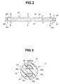
- FIG. 2 is a front view illustrating a configuration of the intracorporeal insertion instrument 21.
- the intracorporeal insertion instrument 21 is configured by including a sheath main body 22 which is an elongated, that is, long double lumen tube, and two guide wires 25, 26 inserted into two lumens 23, 24 which penetrate through from a proximal end portion 22b to a distal end portion 22a of the sheath main body 22. That is, the lumens 23, 24 are formed to allow the respective guide wires as guide tools to be inserted therethrough, and to be able to be protruded from the distal-end openings of the sheath main body 22.
- sheath main body 22 is a double lumen tube having two lumens in the present embodiment, but may be a multiple lumen tube having three or more lumens.
- the sheath main body 22 has a circular cross section and includes inside thereof the two lumens 23, 24 formed along the axis of the sheath main body 22.
- a diameter D1 of the circle of the cross section perpendicular to the axis direction of the sheath main body 22 is 1.2 mm, for example, and the material of the sheath main body is a fluorine resin such as PTFE (polytetrafluoroethylene).
- FIG. 3 is a cross-sectional view of the intracorporeal insertion instrument 21 in FIG. 2 , which is taken along the III-III line.
- the intracorporeal insertion instrument 21 is configured such that cross sections thereof have the same cross-sectional shape at any position.
- the cross sections of the respective lumens 23 and 24, which are taken along the direction perpendicular to the axis of the sheath main body 22, have a non-circular shape, i.e., a semicircular shape in the present embodiment.
- the two lumens 23 and 24 are formed such that inner walls of two plane portions 23a, 24a corresponding to the straight parts of the semicircular shapes are parallel with each other when the sheath main body 22 is straightened.
- the sheath main body 22 has a length about two meters, for example.
- the sheath main body 22 including inside thereof such two lumens 23, 24 can be produced by the publicly-known extrusion molding method.
- the two guide wires 25, 26 are elongated and elastic wires made of stainless steel and have semicircular cross-sectional shapes which are similar to the cross-sectional shapes of the lumens 23, 24 and have a size insertable into the lumens 23, 24. That is, the guide wires 25, 26 have shapes complementary to the cross-sectional shapes of the lumens 23, 24. Therefore, as shown in FIG. 3 , the guide wires 25, 26 respectively have flat portions 25a, 26a and cylindrical surfaces 25b, 26b. The surfaces of the guide wires 25, 26 are coated by fluorine coating, for example.
- the guide wires 25, 26 have cross-sectional shapes having a size capable of preventing the respective guide wires from rotating around the axes of the guide wires in the respective lumens. Therefore, only slight gaps exist between the guide wires 25, 26 and the inner walls of the lumens 23, 24.
- the lengths of the guide wires 25, 26 are equal to or longer than two meters, for example.
- Such guide wires 25, 26 can be formed using a die by passing circular cylinder-shaped members through a semicircular hole of the die and pulling the members.
- the guide wires 25, 26 as shown in FIG. 3 can be produced also by pulling and extending semicircular cylinder-shaped members.
- guide wires 25, 26 as guide tools may be tubular wires, instead of solid wires.
- a bending habit is previously applied to the distal end portions 25t, 26t of the guide wires 25, 26.
- the bending habit is applied to the respective distal end portions 25a, 26a of the guide wires 25, 26 along the axis direction of the respective guide wires such that the distal end portions 25a, 26a bend toward the cylindrical surfaces 25b, 26b of the guide wires 25, 26, respectively.
- the bending habit can be applied by manual operation by a human, for example, by fixing the distal end portions 25t, 26t of the guide wires 25, 26 on a fixing table and drawing the cylindrical surfaces 25b, 26b of the distal end portion 25t, 26t along the axes of the guide wires 25, 26 while pressing a predetermined jig on the cylindrical surfaces.
- the bending habit may be applied over the entire of the guide wires 25, 26, or may be applied at least to the distal end portions 25t, 26t of the guide wires 25, 26. Therefore, the guide wires 25, 26 as guide tools are elongated members configured such that the cross-sectional shapes of at least the distal ends are non-circular and the bending habit along the axis direction is applied to at least the distal end portions.
- the guide wires 25, 26 are inserted from the respective proximal-end openings of the lumens 23, 24, which are located at the proximal end portion 22b of the sheath main body 22.
- the shapes of the two proximal-end openings are the same as the cross-sectional shapes of the lumens 23, 24.
- the guide wires 25, 26 are thin, made of stainless steel, and have elasticity. Therefore, even if the distal end portions 25t, 26t are bent, the guide wires can be easily inserted into the lumens 23, 24 from the respective proximal-end openings.
- the distal end portions 25t, 26t of the guide wires 25, 26 do not contact the inner walls of the lumens 23, 24 to be released, thereby allowing the distal end portions 25t, 26t of the guide wires 25, 26 to bend respectively in the directions in which the bending habit is applied.
- FIG. 4 is a perspective view illustrating the state of the guide wires 25, 26 protruded from the distal end portion 22a of the sheath main body 22.
- the distal end portion 25t, 26t of the guide wires 25, 26 bend toward the cylindrical surfaces 25b, 26b which are the directions in which the bending habit is previously applied. Therefore, the distal end portions 25a, 26a protrude in directions different from each other.
- the distal-end openings 23t, 24t of the lumens 23, 24 at the distal end portion 22a are formed such that the flat surface 25a of the guide wire 25 and the flat surface 26a of the guide wire 26 are opposed to each other at the distal end portion 22a of the sheath main body 22. Therefore, when the guide wires 25, 26 protrude from the distal end portion 22a of the sheath main body 22, the guide wires surely bend in the previously-determined directions different from each other.
- the distal-end openings 23t, 24t are formed so as to prevent the distal end portions 25t, 26t of the guide wires 25, 26 from rotating around the axes thereof. Further, the distal-end openings 23t, 24t are formed such that the distal end portions 25t, 26t are separated from each other as shown by the arrow al along the protruding directions.
- the sheath main body 22 includes a plurality of lumens 23, 24 configured such that a plurality of guide wires 25, 26 are inserted from the plurality of proximal-end openings provided at the proximal end portion 22b and the plurality of guide wires 25, 26 can be protruded from the plurality of distal-end openings 23t, 24t provided at the distal end portion 22a.
- the plurality of distal end openings 23t, 24t are formed at the distal end portion 22a such that the respective guide wires do not rotate around the axes thereof in the distal-end openings and the plurality of distal end portions 25t, 26t of the plurality of guide wires 25, 26 are separated from each other along the protruding directions.
- the directions in which the two guide wires 25, 26 bend are determined by the positions and orientations of the distal-end openings 23t, 24t of the two lumens 23, 24 at the distal end portion 22a of the sheath main body 22, and the directions of bending caused by the bending habit previously applied to the guide wires 25,26.
- the bending habit is previously applied to the respective guide wires 25, 26 so as to bend toward the cylindrical surfaces 25b, 26b, and at the distal end portion 22a of the sheath main body 22, the distal-end openings 23t, 24t of the lumens 23, 24 are formed such that the flat surfaces 25a, 26a of the respective guide wires 25, 26 are opposed to and parallel with each other. Therefore, as shown in FIG. 4 , the distal end portions 25t, 26t of the two guide wires 25, 26, which protrude from the distal end portion 22a, bend in the directions separated from each other as shown by the arrow a1 as going toward the distal end direction in the axis direction of the sheath main body 22.
- the distal end portion 21a of the intracorporeal insertion instrument 21 when the distal end portion 21a of the intracorporeal insertion instrument 21 is at the branch point between the right hepatic duct RHD and the left hepatic duct LHD, the distal end portions 25t, 26t of the guide wires 25, 26 protrude in different directions, which allows the surgeon to easily pass either of the guide wires in a desired bile duct.
- the distal end portions 25t, 26t of the guide wires 25, 26 protrude in different directions also at a branch point Dp2, which is located further ahead, in the right bile duct RHD. Therefore, it is easy for the surgeon to introduce the intracorporeal insertion instrument 21 to a desired site.
- the cross-sectional shapes of the lumens 23, 24 of the sheath main body 22 are the same from the proximal end portion 22b to 22a.
- the guide wires 25, 26 in order to allow the two guide wires 25, 26 to surely bend in different directions at the distal end portion 22a, it is sufficient that the guide wires do not rotate around the axes thereof at the distal-end openings 23t, 24t of the sheath main body 22. Therefore, the cross-sectional shapes of the lumens 23, 24 are not necessarily the same from the proximal end portion 22b to the distal end portion 22a.
- an intracorporeal insertion instrument which has a simple configuration and is suitable for diameter reduction, and which enables a plurality of guide wires to protrude in the directions different from each other.
- the surgeon can rapidly insert the guide wire to a desired position by using such an intracorporeal insertion instrument 21, which reduces a burden on the surgeon and the patient.
- the above-described intracorporeal insertion instrument has a simple structure, the instrument can be produced at reduced cost. Furthermore, since the above-described intracorporeal insertion instrument has a simple structure, cleaning is easy and such an intraporporeal insertion instrument is suitable for reuse.
- each of the plurality of lumens 23, 24 has cross-sectional shapes which are different between the distal end portion 22a and the proximal end portion 22b of the sheath main body 22, and the proximal-end openings of the respective lumens may be made larger than the distal-end openings of the respective lumens.
- FIG. 5 is a perspective view for illustrating the proximal-end openings 23tb, 24tb, diameters of which are expanded at a proximal end portion 22b of the sheath main body 22.
- the respective cross-sectional areas of the proximal-end openings 23tb, 24tb are larger than the respective cross-sectional areas of the lumens 23, 24 in the sheath main body 22. That is, the lumens 23, 24 are formed such that the cross-sectional areas of the respective lumens gradually become larger toward the proximal-end openings 23tb, 24tb in a predetermined range R of the proximal end portion 22b.
- the proximal-end openings 23tb, 24tb can be formed by inserting a jig 31 having a tapered distal end portion into the respective lumens 23, 24 from the proximal end portion 22b of the sheath main body 22.
- a tapered portion 31a of the jig 31 has a part larger than the cross-sectional areas of the lumens 23, 24 in the sheath main body 22.
- the cross-sectional shape of each of the lumens in the sheath main body 22 has a part which gradually changes from the proximal-end opening to the distal-end opening, the shape gently changes from the proximal end portion 22b to the distal end portion 22a, and the diameter of each of the lumens becomes smaller from the proximal end portion 22b to the distal end portion 22a.
- proximal-end openings 23tb, 24tb the opening areas of which are formed to be large, it is easy for the user to insert the guide wires 25, 26 into the lumens 23, 24.
- the sheath main body in the above-described embodiment is one sheath formed from the distal end portion 22a to the proximal end portion 22b.
- the intracorporeal insertion instrument in the modified example 1 includes on the proximal end portion side thereof a plurality of sheath portions branched off for each of the lumens.
- FIG. 6 is a front view of a configuration of the intracorporeal insertion instrument according to the present modified example.
- the proximal end portion 22b of a sheath main body 22A according to the present modified example is bifurcated, as shown in FIG. 5 . That is, the proximal end portion 22b includes sheath portions 22A1, 22A2 which are branched off for each of the lumens.
- the sheath portion 22A1 is the sheath portion of the lumen 23, and the sheath portion 22A2 is the sheath portion of the lumen 24.
- the lengths of the sheath portions 22A1, 22A2 at the bifurcated part is about 20 to 30 cm, for example.
- the proximal end portion 22b of the sheath main body 22A is provided with the sheath portions corresponding to the respective lumens. Therefore, it is easy for the user such as a surgeon to insert the guide wires 25, 26 into the respective lumens 23, 24.
- the lumens 23, 24 at the proximal end portion 22b may be expanded so as to facilitate the insertion of the guide wires 25, 26.
- FIG. 7 illustrates the proximal-end opening viewed from the proximal end side shown by the arrow Vp in FIG. 6 .
- the inner diameter d2 of the proximal-end openings of the sheath portions 22A1, 22A2 is expanded, it is easy for the user to insert the guide wires 25, 26 into the lumens 23, 24, respectively.
- the inner diameters of the proximal-end openings can be expanded by using the above-described jig 31 having a tapered portion whose cross section is a circular shape.
- An intracorporeal insertion instrument according to the modified example 2 is formed such that the user can distinguish between the flat portion and the cylindrical surface when inserting the guide wires from the proximal end portion 22b.
- the user can discriminate the respective orientations of the guide wires and the sheath main body. Therefore, the user can easily insert the guide wires into the lumens.
- FIG. 8 illustrates the intracorporeal insertion instrument according to the present modified example.
- a linear colored portion 41 whose color is different from the color of the outer circumferential surface of the sheath main body 22 is provided on the side of each of the cylindrical surfaces 23b, 24b of the lumens along the axis direction of the sheath main body 22.
- a linear colored portion whose color is different from the color of the guide wire 25 is provided also on the cylindrical surface 25b of the guide wire 25.
- the two linear colored portions 41 are provided on at least the outer circumferential surface of the proximal end portion 22b of the sheath main body 22.
- the respective lumens 23, 24 are formed such that the cylindrical surfaces 23b, 24b face toward the outer circumferential side of the sheath main body 22. Accordingly, the colored portions 41 are provided at the positions close to the top portions of the cylindrical surfaces of the respective lumens.
- the colored portions 42 are provided to the guide wires 25, 26, along the top portions of the cylindrical surfaces 25b, 26b.
- the colored portions 41, 42 can be provided to the sheath main body 22 or the guide wires 25, 26 by applying paint of a predetermined color.
- the colored portions 41 are provided on the outer circumferential surface of the sheath main body 22 along the vicinity of the top portions of the parts forming circular arcs on the cross sections of the respective lumens 23, 24, and also the colored portions 42 are provided to the guide wires 25, 26, along the top portions of the parts forming circular arcs on the cross sections of the guide wires.
- the colored portions 41, 42 are provided to the sheath main body 22 and the respective guide wires, as the indicators for positioning in the circumferential direction of the insertion axis of the respective guide wires at the proximal-end openings of the sheath main body 22.
- the user when viewing the sheath main body 22 and the guide wires 25, 26, the user can insert the guide wires 25, 26 having non-circular cross-sectional shapes into the proximal-end openings 23tb, 24tb having non-circular cross-sectional shapes. Therefore, the user can easily insert the guide wires into the lumens of the sheath main body.
- each of the distal-end openings and the cross-sectional shape of each of the distal end portions of the guide wires are semicircular shape, but may be other shapes.
- FIG. 9 and FIG. 10 illustrate other examples of the shapes of the distal-end openings of the sheath main body and the shapes of the guide wires.
- FIG. 9 is a cross-sectional view of an intracorporeal insertion instrument in which a sheath main body includes four lumens.
- a sheath main body 22B includes inside thereof four lumens 51, and is configured such that guide wires 52 are insertable into the respective lumens 51.
- the shapes of the distal-end openings of the sheath main body 22B are the same as the cross-sectional shapes of the lumens 51 shown in FIG. 9 . That is, the shapes of the plurality of distal-end openings are different from one another.
- each of the distal-end openings of the respective lumens 51 is a sector shape
- the cross-sectional shape of each of the guide wires 52 is also a sector shape analogous to but smaller than the sector shape of each of the lumens 51.
- a bending habit is applied to the distal end portion of each of the guide wires 52 so as to bend toward each of the cylindrical surfaces 52a.
- the intracorporeal insertion instrument as shown in FIG. 9 enables the plurality of guide wires 52 to protrude in the directions different from each other.
- FIG. 10 is a cross-sectional view of the intracorporeal insertion instrument having a plurality of lumens of different shapes.
- a sheath main body 22C includes inside thereof two lumens 61, 62, and the lumens 61, 62 allow guide wires 63, 64 to be inserted therethrough.
- the shapes of the distal-end openings of the sheath main body 22C are the same as the cross-sectional shapes of the lumens 61, 62 shown in FIG. 10 , respectively.
- the shape of the distal-end opening of the lumen 61 is a sector shape and the cross-sectional shape of the guide wire 63 is also a sector shape analogous to but smaller than the sector shape of the lumen 61.
- a bending habit is applied to the distal end portion of the guide wire 63 so as to bend toward the cylindrical surface 63 a.
- the shape of the distal-end opening of the lumen 62 is a semicircular shape, and also the cross-sectional shape of the guide wire 64 is a semicircular shape analogous to but smaller than the sector shape of the lumen 62.
- a bending habit is applied to the distal end portion of the guide wire 64 so as to bend toward a flat surface 64a.
- the intracorporeal insertion instrument shown in FIG. 10 enables the plurality of guide wires 63, 64 having shapes different from each other to protrude in directions different from each other.
- an identification tag as identification means may be provided to each of the guide wires and the sheath main body so that the plurality of guide wires having shapes different from each other can be correctly inserted into corresponding lumens, respectively.
- tags 81 a and 81 b each of which indicates a type, a shape, and the like of the guide wire to be inserted, are attached to the respective sheath portions, and also tags 82a and 82b, each of which indicates a type, a shape, and the like of the guide wire, are attached to the respective guide wires.
- each of the tags is an adhesive seal or the like, on which a character, a sign or the like indicating a type, etc. is printed, and is pasted on each of the sheath portions of the proximal end portion 22b and each of the proximal ends of the guide wires by making use of the adherence property of the seal.
- the tag 82a is pasted on the guide wire 63 which is one of the two guide wires having different shapes as shown in FIG. 10 , for example, and when the sheath portion of the corresponding lumen 61 is a sheath portion 22A1, the tag 81a is pasted on the sheath portion 22A1. If the tags 81 a and 82a have the same sign, mark and the like, the user can easily recognize that the guide wire 63 should be inserted into the sheath portion 22A1. The same is true for the guide wire 64 and the lumen 62.
- the user can easily insert the guide wires into the correct lumens by using such tags.
- each of the distal-end openings may be a triangle shape, a trapezoid shape, a star shape, or the like, instead of the above-described semicircular shape and the sector shape.
- an intracorporeal insertion instrument which has a simple configuration and is suitable for diameter reduction, and which enables a plurality of guide wires to protrude in directions different from each other.
- a plurality of lumens are formed in the sheath main body and the guide wires are inserted into the respective lumens.
- the sheath main body includes one lumen into which a plurality of guide wires are insertable.
- FIG. 11 is a cross-sectional view of the intracorporeal insertion instrument 21 according to the present embodiment.
- the members corresponding to those in the above-described first embodiment are made of the same materials and produced in the same production method.
- a sheath main body 22D includes one lumen 71 into which three guide wires 72 are insertable.
- Each of the guide wires 72 is a member having substantially circular cross section and including a protruding portion 72a along an axis direction. A bending habit is applied to each of the distal end portions of the guide wires 72 so as to bend toward the protruding portion 72a.
- the lumen 71 is provided with three groove portions 71 a which are engaged with the protruding portions 72a of the three guide wires 72 and which are formed along the axis direction.
- the user such as a surgeon can insert the three guide wires 72 from the proximal-end opening of the proximal end portion 22b of the sheath main body 22D in a state where the protruding portions 72a of the respective guide wires 71 are engaged with the respective groove portions 71a.
- the protruding portions 72a enter into the groove portions 71 a, respectively, which prevents the three guide wires 72 from rotating in the axis direction.
- the sheath main body 22D includes the single lumen 71 formed such that the plurality of guide wires are inserted from the proximal-end opening provided at the proximal end portion 22b and the plurality of guide wires can be protruded from the distal-end opening provided at the distal end portion 22a.
- the distal-end opening is formed such that the respective guide wires are prevented from rotating around the axes of the respective guide wires in the one distal-end opening, and the plurality of the distal end portions of the plurality of guide wires are separated from each other along the protruding directions.
- the three guide wires protrude from the distal-end opening of the lumen 71 of the sheath main body 22D in directions different from each other.
- the present embodiment has the same effects as those in the first embodiment, and configured such that the plurality of guide wires can be inserted into the one lumen, the diameter of the sheath main body 22D can be made smaller than the diameter of the sheath main body in the first embodiment.
- an intracorporeal insertion instrument which has a simple configuration and is suitable for diameter reduction, and which enables a plurality of guide wires to protrude in directions different from each other.
Landscapes
- Health & Medical Sciences (AREA)
- Life Sciences & Earth Sciences (AREA)
- Public Health (AREA)
- Biophysics (AREA)
- Engineering & Computer Science (AREA)
- Biomedical Technology (AREA)
- Heart & Thoracic Surgery (AREA)
- Veterinary Medicine (AREA)
- Animal Behavior & Ethology (AREA)
- General Health & Medical Sciences (AREA)
- Surgery (AREA)
- Anesthesiology (AREA)
- Hematology (AREA)
- Pulmonology (AREA)
- Physics & Mathematics (AREA)
- Nuclear Medicine, Radiotherapy & Molecular Imaging (AREA)
- Optics & Photonics (AREA)
- Pathology (AREA)
- Radiology & Medical Imaging (AREA)
- Medical Informatics (AREA)
- Molecular Biology (AREA)
- Media Introduction/Drainage Providing Device (AREA)
Abstract
Description
- The present invention relates to an intracorporeal insertion instrument.
- Conventionally, intracorporeal insertion instruments have been used for various examinations and various treatments in medical fields. Intracorporeal insertion instruments include a catheter for CTO (chronic total occlusion), a guide wire for allowing passage through a narrowed area in a bile duct or a pancreatic duct, or the like.
- For example, in ERCP (endoscopic retrograde cholangiopancreatography), an endoscope is used, and a contrast agent is injected from the duodenal papilla, to confirm the narrowed area of the bile duct while viewing an X-ray image, and treatment for expanding the narrowed area of the bile duct by inserting a stent and the like into the narrowed area using a guide wire.
- In this case, the intracorporeal insertion instrument is inserted close to such a narrowed area. Since the bile duct or the like intricately branches off, it is not easy for a surgeon to select one branched duct having a narrowed area among a plurality of branched ducts which branch off in a plurality of directions and insert and place a guide wire in the selected branched duct, while viewing an X-ray image. Same is true for a catheter used for a therapy of CTO (chronic total occlusion).
- Japanese Unexamined Patent Application Publication (Translation of PCT Application) No.
2008-509718 - Further, Japanese Unexamined Patent Application Publication (Translation of PCT Application) No.
2011-500191 - However, as in the catheter tool according to the first proposal, even if the bending habit is previously applied to the guide wire, a plurality of guide wires are not necessarily bent in different directions when the guide wires are released from a distal end portion of the catheter. This is because the guide wire rotates in the axial direction of the guide wire in the guide tube of the catheter and a direction of the bending habit of the guide wire is indefinite when the guide wire is protruded from the distal end portion of the catheter.
- Further, in the case of the catheter tool according to the second proposal, a configuration for changing the separating distance between the two guide wires is required for changing the moving direction of the guide wires, and therefore there arises a problem that the configuration is complicated to result in making a diameter of the catheter tool thick. Furthermore, since the surgeon is required to perform an operation for inflation of the balloon, the surgeon has to perform, while holding the catheter tool by one hand, the inflation operation of the balloon and the insertion operation of the guide wires by the other hand, so that operability is not good.
- Therefore, the present invention has been made in view of the foregoing problems and an object of the present invention is to provide an intracorporeal insertion instrument which is simple in configuration and suitable for diameter reduction, and is configured such that a plurality of guide wires are protruded in directions different from each other.
- An intracorporeal insertion instrument according to one aspect of the present invention comprises: a plurality of elongated guide tools wherein a cross-sectional shape of at least a distal end portion is non-circular shape and a bending habit is applied to at least the distal end portion; and a sheath main body including a plurality of lumens formed such that the plurality of guide tools are inserted from a plurality of proximal-end openings provided at a proximal end portion to be capable of protruding from a plurality of distal-end openings provided at a distal end portion, wherein the plurality of distal-end openings are formed such that the respective guide tools do not rotate around axes of the respective guide tools at the respective distal-end openings and a plurality of distal end portions of the plurality of guide tools separate from each other along protruding directions.
- An intracorporeal insertion instrument according to another aspect of the present invention comprises: a plurality of elongated guide tools wherein a cross-sectional shape of at least a distal end portion is non-circular shape and a bending habit is applied to at least the distal end portion; and a sheath main body including one lumen formed such that the plurality of guide tools are inserted from a proximal-end opening provided at a proximal end portion to be capable of protruding from a distal-end opening provided at a distal end portion, wherein the distal-end opening is formed such that the respective guide tools do not rotate around axes of the respective guide tools at the distal-end opening and the plurality of distal end portions of the plurality of guide tools separate from each other along protruding directions.
-
-
FIG. 1 relates to a first embodiment of the present invention, and illustrates a state where a guide wire is inserted in a desired direction at one branch point in a bile duct in ERCP (Endoscopic retrograde cholangiopancreatography). -
FIG. 2 is a front view illustrating a configuration of anintracorporeal insertion instrument 21 according to the first embodiment of the present invention. -
FIG. 3 is a cross-sectional view of theintracorporeal insertion instrument 21 inFIG. 2 , which is taken along the III-III line. -
FIG. 4 is a perspective view illustrating a state of theguide wires distal end portion 22a of a sheathmain body 22 according to the first embodiment of the present invention. -
FIG. 5 is a perspective view illustrating proximal-end openings 23tb, 24tb, diameters of which are expanded at aproximal end portion 22b of the sheathmain body 22, according to the first embodiment of the present invention. -
FIG. 6 is a front view of a configuration of an intracorporeal insertion instrument according to a modified example 1 of the first embodiment of the present invention. -
FIG. 7 illustrates the proximal-end opening viewed from the proximal end side shown by the arrow Vp inFIG. 6 . -
FIG. 8 illustrates an intracorporeal insertion instrument according to a modified example 2 of the first embodiment of the present invention. -
FIG. 9 illustrates another example of the shapes of the distal-end openings of the sheath main body and the shapes of the guide wires, according to a modified example 3 of the first embodiment of the present invention. -
FIG. 10 illustrates yet another example of the shapes of the distal-end openings of the sheath main body and the shapes of the guide wires, according to the modified example 3 of the first embodiment of the present invention. -
FIG. 11 is a cross-sectional view of anintracorporeal insertion instrument 21 according to a second embodiment of the present invention. - Hereinafter, embodiments of the present invention will be described with reference to drawings.
- Note that, in the drawings used in the description below, a different scale size is used for each of the components in order to allow each of the components to be illustrated in a recognizable size in the drawings, and the present invention is not limited to the number, shapes, ratio of the sizes of the components, and a relative positional relationship among the components shown in these drawings.
- The present embodiment will be described using an example of an intracorporeal insertion instrument including a plurality of guide wires for a bile duct and a sheath main body through which the plurality of guide wires are inserted.
FIG. 1 illustrates a state where a guide wire is inserted in a desired direction at one branch point in a bile duct in ERCP (endoscopic retrograde cholangiopancreatography). -
FIG. 1 illustrates a state where adistal end portion 11A of aninsertion portion 11 of an endoscope inserted from the mouth of a subject passes through the esophagus ES and the stomach ST to reach in the vicinity of the papilla Vater AV of the duodenum DU. In a treatment instrument insertion channel inserted in theinsertion portion 11 of the endoscope, anintracorporeal insertion instrument 21 for bile duct is inserted. The endoscope is a lateral-view endoscope, and is configured such that theintracorporeal insertion instrument 21 can be protruded from an opening portion of thedistal end portion 11A of theinsertion portion 11. - A surgeon operates a raising stand of the
distal end portion 11A while viewing an image displayed on a monitor (not shown) of the endoscope apparatus, thereby capable of guiding the distal end of theintracorporeal insertion section 21 to an orifice of the papilla Vater AV. InFIG. 1 , theintracorporeal insertion instrument 21 passes from the papilla Vater AV through the common bile duct CD not through the main pancreatic duct MPD. The surgeon passes theintracorporeal insertion instrument 21 through the common bile duct CD, and further enables adistal end portion 21a of theintracorporeal insertion instrument 21 to advance toward the liver LV while viewing the X-ray image. A distal end portion of the common hepatic duct CHD on the distal end side of the common bile duct CD branches off into the right hepatic duct RHD and the left hepatic duct LHD, and the respective tips of the right hepatic duct RHD and the left hepatic duct LHD further branch off. The bile duct finely branches off and forms a dendritic network, to be a bile capillary in the liver LV. -
FIG. 1 illustrates a state where the distal end portion 2 1 a of theintracorporeal insertion instrument 21 is located at a branch point Dp1 between the right hepatic duct RHD and the left hepatic duct LHD in the common hepatic duct CHD. -
FIG. 2 is a front view illustrating a configuration of theintracorporeal insertion instrument 21. Theintracorporeal insertion instrument 21 is configured by including a sheathmain body 22 which is an elongated, that is, long double lumen tube, and twoguide wires lumens proximal end portion 22b to adistal end portion 22a of the sheathmain body 22. That is, thelumens main body 22. - Note that the sheath
main body 22 is a double lumen tube having two lumens in the present embodiment, but may be a multiple lumen tube having three or more lumens. - The sheath
main body 22 has a circular cross section and includes inside thereof the twolumens main body 22. A diameter D1 of the circle of the cross section perpendicular to the axis direction of the sheathmain body 22 is 1.2 mm, for example, and the material of the sheath main body is a fluorine resin such as PTFE (polytetrafluoroethylene). -
FIG. 3 is a cross-sectional view of theintracorporeal insertion instrument 21 inFIG. 2 , which is taken along the III-III line. As shown inFIG. 3 , theintracorporeal insertion instrument 21 is configured such that cross sections thereof have the same cross-sectional shape at any position. The cross sections of therespective lumens main body 22, have a non-circular shape, i.e., a semicircular shape in the present embodiment. - As shown in
FIG. 3 , the twolumens plane portions main body 22 is straightened. The sheathmain body 22 has a length about two meters, for example. The sheathmain body 22 including inside thereof such twolumens - The two
guide wires lumens lumens guide wires lumens FIG. 3 , theguide wires flat portions cylindrical surfaces guide wires - Furthermore, the
guide wires guide wires lumens guide wires -
Such guide wires guide wires FIG. 3 can be produced also by pulling and extending semicircular cylinder-shaped members. - Note that the
guide wires - A bending habit is previously applied to the
distal end portions guide wires distal end portions guide wires distal end portions cylindrical surfaces guide wires - The bending habit can be applied by manual operation by a human, for example, by fixing the
distal end portions guide wires cylindrical surfaces distal end portion guide wires - Note that the bending habit may be applied over the entire of the
guide wires distal end portions guide wires guide wires - The
guide wires lumens proximal end portion 22b of the sheathmain body 22. The shapes of the two proximal-end openings are the same as the cross-sectional shapes of thelumens guide wires distal end portions lumens - When the
guide wires lumens distal end portions distal end portion 22a of the sheathmain body 22, thedistal end portions guide wires lumens distal end portions guide wires -
FIG. 4 is a perspective view illustrating the state of theguide wires distal end portion 22a of the sheathmain body 22. As shown inFIG. 4 , if theguide wires end openings lumens distal end portion guide wires cylindrical surfaces distal end portions - The distal-
end openings lumens distal end portion 22a are formed such that theflat surface 25a of theguide wire 25 and theflat surface 26a of theguide wire 26 are opposed to each other at thedistal end portion 22a of the sheathmain body 22. Therefore, when theguide wires distal end portion 22a of the sheathmain body 22, the guide wires surely bend in the previously-determined directions different from each other. - The distal-
end openings distal end portions guide wires end openings distal end portions - That is, the sheath
main body 22 includes a plurality oflumens guide wires proximal end portion 22b and the plurality ofguide wires end openings distal end portion 22a. Furthermore, the plurality ofdistal end openings distal end portion 22a such that the respective guide wires do not rotate around the axes thereof in the distal-end openings and the plurality ofdistal end portions guide wires - Therefore, the directions in which the two
guide wires end openings lumens distal end portion 22a of the sheathmain body 22, and the directions of bending caused by the bending habit previously applied to theguide wires - In the above-described example, the bending habit is previously applied to the
respective guide wires cylindrical surfaces distal end portion 22a of the sheathmain body 22, the distal-end openings lumens flat surfaces respective guide wires FIG. 4 , thedistal end portions guide wires distal end portion 22a, bend in the directions separated from each other as shown by the arrow a1 as going toward the distal end direction in the axis direction of the sheathmain body 22. - For example, as shown in
FIG. 1 , when thedistal end portion 21a of theintracorporeal insertion instrument 21 is at the branch point between the right hepatic duct RHD and the left hepatic duct LHD, thedistal end portions guide wires - Furthermore, as shown by the dotted lines in
FIG. 1 , for example, thedistal end portions guide wires intracorporeal insertion instrument 21 to a desired site. - Note that the cross-sectional shapes of the
lumens main body 22 are the same from theproximal end portion 22b to 22a. However, as shown inFIG. 4 , in order to allow the twoguide wires distal end portion 22a, it is sufficient that the guide wires do not rotate around the axes thereof at the distal-end openings main body 22. Therefore, the cross-sectional shapes of thelumens proximal end portion 22b to thedistal end portion 22a. - As described above, according to the present embodiment, it is possible to provide an intracorporeal insertion instrument which has a simple configuration and is suitable for diameter reduction, and which enables a plurality of guide wires to protrude in the directions different from each other. As a result, the surgeon can rapidly insert the guide wire to a desired position by using such an
intracorporeal insertion instrument 21, which reduces a burden on the surgeon and the patient. - In addition, since the above-described intracorporeal insertion instrument has a simple structure, the instrument can be produced at reduced cost. Furthermore, since the above-described intracorporeal insertion instrument has a simple structure, cleaning is easy and such an intraporporeal insertion instrument is suitable for reuse.
- Note that the opening area of the proximal-end openings 23tb and 24tb may be formed to be large at the
proximal end portion 22b of the sheathmain body 22 in order to facilitate the insertion of theguide wires lumens distal end portion 22a and theproximal end portion 22b of the sheathmain body 22, and the proximal-end openings of the respective lumens may be made larger than the distal-end openings of the respective lumens. -
FIG. 5 is a perspective view for illustrating the proximal-end openings 23tb, 24tb, diameters of which are expanded at aproximal end portion 22b of the sheathmain body 22. As shown inFIG. 5 , the respective cross-sectional areas of the proximal-end openings 23tb, 24tb are larger than the respective cross-sectional areas of thelumens main body 22. That is, thelumens proximal end portion 22b. - As shown in
FIG. 5 , insuch lumens jig 31 having a tapered distal end portion into therespective lumens proximal end portion 22b of the sheathmain body 22. A taperedportion 31a of thejig 31 has a part larger than the cross-sectional areas of thelumens main body 22. - In other words, the cross-sectional shape of each of the lumens in the sheath
main body 22 has a part which gradually changes from the proximal-end opening to the distal-end opening, the shape gently changes from theproximal end portion 22b to thedistal end portion 22a, and the diameter of each of the lumens becomes smaller from theproximal end portion 22b to thedistal end portion 22a. - According to the proximal-end openings 23tb, 24tb, the opening areas of which are formed to be large, it is easy for the user to insert the
guide wires lumens - Hereinafter, modified examples of the present embodiment are described.
- As shown in
FIG. 2 , the sheath main body in the above-described embodiment is one sheath formed from thedistal end portion 22a to theproximal end portion 22b. However, the intracorporeal insertion instrument in the modified example 1 includes on the proximal end portion side thereof a plurality of sheath portions branched off for each of the lumens. -
FIG. 6 is a front view of a configuration of the intracorporeal insertion instrument according to the present modified example. Theproximal end portion 22b of a sheathmain body 22A according to the present modified example is bifurcated, as shown inFIG. 5 . That is, theproximal end portion 22b includes sheath portions 22A1, 22A2 which are branched off for each of the lumens. The sheath portion 22A1 is the sheath portion of thelumen 23, and the sheath portion 22A2 is the sheath portion of thelumen 24. The lengths of the sheath portions 22A1, 22A2 at the bifurcated part is about 20 to 30 cm, for example. - The
proximal end portion 22b of the sheathmain body 22A is provided with the sheath portions corresponding to the respective lumens. Therefore, it is easy for the user such as a surgeon to insert theguide wires respective lumens - Furthermore, also in the present modified example, the
lumens proximal end portion 22b may be expanded so as to facilitate the insertion of theguide wires -
FIG. 7 illustrates the proximal-end opening viewed from the proximal end side shown by the arrow Vp inFIG. 6 . As shown inFIG. 7 , since the inner diameter d2 of the proximal-end openings of the sheath portions 22A1, 22A2 is expanded, it is easy for the user to insert theguide wires lumens jig 31 having a tapered portion whose cross section is a circular shape. - An intracorporeal insertion instrument according to the modified example 2 is formed such that the user can distinguish between the flat portion and the cylindrical surface when inserting the guide wires from the
proximal end portion 22b. The user can discriminate the respective orientations of the guide wires and the sheath main body. Therefore, the user can easily insert the guide wires into the lumens. -
FIG. 8 illustrates the intracorporeal insertion instrument according to the present modified example. On the outer circumferential side of the sheathmain body 22 of theproximal end portion 22b, a linearcolored portion 41 whose color is different from the color of the outer circumferential surface of the sheathmain body 22 is provided on the side of each of thecylindrical surfaces 23b, 24b of the lumens along the axis direction of the sheathmain body 22. Similarly, a linear colored portion whose color is different from the color of theguide wire 25 is provided also on thecylindrical surface 25b of theguide wire 25. - Specifically, the two linear
colored portions 41 are provided on at least the outer circumferential surface of theproximal end portion 22b of the sheathmain body 22. As shown inFIG. 3 , therespective lumens cylindrical surfaces 23b, 24b face toward the outer circumferential side of the sheathmain body 22. Accordingly, thecolored portions 41 are provided at the positions close to the top portions of the cylindrical surfaces of the respective lumens. - Also, the
colored portions 42 are provided to theguide wires cylindrical surfaces - Note that the
colored portions main body 22 or theguide wires - That is, the
colored portions 41 are provided on the outer circumferential surface of the sheathmain body 22 along the vicinity of the top portions of the parts forming circular arcs on the cross sections of therespective lumens colored portions 42 are provided to theguide wires colored portions main body 22 and the respective guide wires, as the indicators for positioning in the circumferential direction of the insertion axis of the respective guide wires at the proximal-end openings of the sheathmain body 22. - As a result, if the user inserts the
guide wires proximal end portion 22b of the sheathmain body 22 such that thecolored portions main body 22 and theguide wires guide wires - In the above-described embodiment and the respective modified examples, the shape of each of the distal-end openings and the cross-sectional shape of each of the distal end portions of the guide wires are semicircular shape, but may be other shapes.
-
FIG. 9 andFIG. 10 illustrate other examples of the shapes of the distal-end openings of the sheath main body and the shapes of the guide wires. -
FIG. 9 is a cross-sectional view of an intracorporeal insertion instrument in which a sheath main body includes four lumens. As shown inFIG. 9 , a sheathmain body 22B includes inside thereof fourlumens 51, and is configured such thatguide wires 52 are insertable into therespective lumens 51. The shapes of the distal-end openings of the sheathmain body 22B are the same as the cross-sectional shapes of thelumens 51 shown inFIG. 9 . That is, the shapes of the plurality of distal-end openings are different from one another. - The shape of each of the distal-end openings of the
respective lumens 51 is a sector shape, and the cross-sectional shape of each of theguide wires 52 is also a sector shape analogous to but smaller than the sector shape of each of thelumens 51. A bending habit is applied to the distal end portion of each of theguide wires 52 so as to bend toward each of thecylindrical surfaces 52a. - Therefore, also the intracorporeal insertion instrument as shown in
FIG. 9 enables the plurality ofguide wires 52 to protrude in the directions different from each other. -
FIG. 10 is a cross-sectional view of the intracorporeal insertion instrument having a plurality of lumens of different shapes. As shown inFIG. 10 , a sheathmain body 22C includes inside thereof twolumens lumens guide wires main body 22C are the same as the cross-sectional shapes of thelumens FIG. 10 , respectively. - The shape of the distal-end opening of the
lumen 61 is a sector shape and the cross-sectional shape of theguide wire 63 is also a sector shape analogous to but smaller than the sector shape of thelumen 61. A bending habit is applied to the distal end portion of theguide wire 63 so as to bend toward thecylindrical surface 63 a. - The shape of the distal-end opening of the
lumen 62 is a semicircular shape, and also the cross-sectional shape of theguide wire 64 is a semicircular shape analogous to but smaller than the sector shape of thelumen 62. A bending habit is applied to the distal end portion of theguide wire 64 so as to bend toward aflat surface 64a. - Therefore, also the intracorporeal insertion instrument shown in
FIG. 10 enables the plurality ofguide wires - Note that an identification tag as identification means may be provided to each of the guide wires and the sheath main body so that the plurality of guide wires having shapes different from each other can be correctly inserted into corresponding lumens, respectively.
- For example, in
FIG. 6 , as shown by the one-dot chain lines, when theproximal end portion 22b has a sheath portion for each of the guide wires, tags 81 a and 81 b, each of which indicates a type, a shape, and the like of the guide wire to be inserted, are attached to the respective sheath portions, and also tags 82a and 82b, each of which indicates a type, a shape, and the like of the guide wire, are attached to the respective guide wires. For example, each of the tags is an adhesive seal or the like, on which a character, a sign or the like indicating a type, etc. is printed, and is pasted on each of the sheath portions of theproximal end portion 22b and each of the proximal ends of the guide wires by making use of the adherence property of the seal. - The
tag 82a is pasted on theguide wire 63 which is one of the two guide wires having different shapes as shown inFIG. 10 , for example, and when the sheath portion of thecorresponding lumen 61 is a sheath portion 22A1, thetag 81a is pasted on the sheath portion 22A1. If thetags guide wire 63 should be inserted into the sheath portion 22A1. The same is true for theguide wire 64 and thelumen 62. - Therefore, the user can easily insert the guide wires into the correct lumens by using such tags.
- Furthermore, the shape of each of the distal-end openings may be a triangle shape, a trapezoid shape, a star shape, or the like, instead of the above-described semicircular shape and the sector shape.
- As described above, according to the above-described embodiment and the respective modified examples, it is possible to provide an intracorporeal insertion instrument which has a simple configuration and is suitable for diameter reduction, and which enables a plurality of guide wires to protrude in directions different from each other.
- In the above-described embodiment, a plurality of lumens are formed in the sheath main body and the guide wires are inserted into the respective lumens. However, in the present embodiment, the sheath main body includes one lumen into which a plurality of guide wires are insertable.
-
FIG. 11 is a cross-sectional view of theintracorporeal insertion instrument 21 according to the present embodiment. InFIG. 11 , the members corresponding to those in the above-described first embodiment are made of the same materials and produced in the same production method. - As shown in
FIG. 11 , a sheathmain body 22D includes onelumen 71 into which threeguide wires 72 are insertable. - Each of the
guide wires 72 is a member having substantially circular cross section and including a protrudingportion 72a along an axis direction. A bending habit is applied to each of the distal end portions of theguide wires 72 so as to bend toward the protrudingportion 72a. - On the other hand, the
lumen 71 is provided with threegroove portions 71 a which are engaged with the protrudingportions 72a of the threeguide wires 72 and which are formed along the axis direction. The user such as a surgeon can insert the threeguide wires 72 from the proximal-end opening of theproximal end portion 22b of the sheathmain body 22D in a state where the protrudingportions 72a of therespective guide wires 71 are engaged with therespective groove portions 71a. - As shown in
FIG. 11 , in thelumen 71, the protrudingportions 72a enter into thegroove portions 71 a, respectively, which prevents the threeguide wires 72 from rotating in the axis direction. - That is, in the present embodiment, the sheath
main body 22D includes thesingle lumen 71 formed such that the plurality of guide wires are inserted from the proximal-end opening provided at theproximal end portion 22b and the plurality of guide wires can be protruded from the distal-end opening provided at thedistal end portion 22a. In addition, the distal-end opening is formed such that the respective guide wires are prevented from rotating around the axes of the respective guide wires in the one distal-end opening, and the plurality of the distal end portions of the plurality of guide wires are separated from each other along the protruding directions. - Therefore, the three guide wires protrude from the distal-end opening of the
lumen 71 of the sheathmain body 22D in directions different from each other. - Note that, also regarding the present second embodiment, the respective modified examples 1 to 3 described in the first embodiment are applicable.
- The present embodiment has the same effects as those in the first embodiment, and configured such that the plurality of guide wires can be inserted into the one lumen, the diameter of the sheath
main body 22D can be made smaller than the diameter of the sheath main body in the first embodiment. - As described above, according to the above-described two embodiments and the respective modified examples, it is possible to provide an intracorporeal insertion instrument which has a simple configuration and is suitable for diameter reduction, and which enables a plurality of guide wires to protrude in directions different from each other.
- Note that description was made in the above-described examples by taking the intracorporeal insertion instrument for bile duct as an example. However, the above-described examples can be applied to intracorporeal insertion instruments for blood vessels of the heart, blood vessels in the brain, and the like.
- The present invention is not limited to the above-described embodiments, and various changes, modifications, and the like are possible without departing from the gist of the invention.
- The present application is filed claiming the priority of Japanese Patent Application No.
2011-134500 filed in Japan on June 16, 2011, and the above described disclosure is incorporated by reference in the present description and claims.
Claims (15)
- An intracorporeal insertion instrument comprising:a plurality of elongated guide tools wherein a cross-sectional shape of at least a distal end portion is non-circular shape and a bending habit is applied to at least the distal end portion; anda sheath main body including a plurality of lumens formed such that the plurality of guide tools are inserted from a plurality of proximal-end openings provided at a proximal end portion to be capable of protruding from a plurality of distal-end openings provided at a distal end portion, wherein the plurality of distal-end openings are formed such that the respective guide tools do not rotate around axes of the respective guide tools at the respective distal-end openings and a plurality of distal end portions of the plurality of guide tools separate from each other along protruding directions.
- The intracorporeal insertion instrument according to claim 1, wherein each of the plurality of lumens has cross-sectional shapes which are different between the distal end portion and the proximal end portion of the sheath main body, and the proximal-end opening of each of the lumens is larger than the distal-end opening.
- The intracorporeal insertion instrument according to claim 2, wherein the cross-sectional shape of each of the plurality of lumens has a part changing gradually from the proximal-end opening toward the distal-end opening.
- The intracorporeal insertion instrument according to any one of claims 1 to 3, wherein shapes of the plurality of distal-end openings are different from each other.
- The intracorporeal insertion instrument according to claim 1, wherein the sheath main body includes a plurality of sheath portions which branch off for each of the lumens at the proximal end portion of the sheath main body.
- The intracorporeal insertion instrument according to claim 5, wherein an inner diameter of each of the proximal-end openings is expanded at each sheath portion.
- The intracorporeal insertion instrument according to claim 1, wherein the cross-sectional shapes of at least the distal end portions of the plurality of guide tools are the same, and at least the distal end portions have the cross-sectional shapes complementary to cross-sectional shapes of the plurality of distal-end openings of the sheath main body.
- The intracorporeal insertion instrument according to claim 1, wherein the cross-sectional shape of at least the distal end portion of each of the plurality of guide tools is a semicircular shape, a sector shape, a triangle shape, a trapezoidal shape, or a star shape.
- The intracorporeal insertion instrument according to any one of claims 1 to 3, wherein the plurality of guide tools are wires.
- The intracorporeal insertion according to claim 9, the wires are solid or tubular wires.
- The intracorporeal insertion instrument according to claim 10, wherein surfaces of the plurality of guide tools are coated.
- The intracorporeal insertion instrument according to claim 1, wherein each of the plurality of guide tools and the sheath main body are provided with an indicator portion for positioning of the guide tool in a circumferential direction of an insertion axis at the proximal-end opening.
- An intracorporeal insertion instrument comprising:a plurality of elongated guide tools wherein a cross-sectional shape of at least a distal end portion is non-circular shape and a bending habit is applied to at least the distal end portion; anda sheath main body including one lumen formed such that the plurality of guide tools are inserted from a proximal-end opening provided at a proximal end portion to be capable of protruding from a distal-end opening provided at a distal end portion, wherein the distal-end opening is formed such that the respective guide tools do not rotate around axes of the respective guide tools at the distal-end opening and the plurality of distal end portions of the plurality of guide tools separate from each other along protruding directions.
- The intracorporeal insertion instrument according to claim 13, wherein the sheath main body includes a plurality of sheath portions which branch off for each of the guide tools at the proximal end portion of the sheath main body.
- The intracorporeal insertion instrument according to claim 14, wherein an inner diameter of each of the proximal-end openings is expanded at each of the sheath portions.
Applications Claiming Priority (2)
| Application Number | Priority Date | Filing Date | Title |
|---|---|---|---|
| JP2011134500 | 2011-06-16 | ||
| PCT/JP2012/061767 WO2012172885A1 (en) | 2011-06-16 | 2012-05-08 | Somatic insertion tool |
Publications (3)
| Publication Number | Publication Date |
|---|---|
| EP2703037A1 true EP2703037A1 (en) | 2014-03-05 |
| EP2703037A4 EP2703037A4 (en) | 2014-10-29 |
| EP2703037B1 EP2703037B1 (en) | 2016-04-27 |
Family
ID=47356881
Family Applications (1)
| Application Number | Title | Priority Date | Filing Date |
|---|---|---|---|
| EP12799938.1A Not-in-force EP2703037B1 (en) | 2011-06-16 | 2012-05-08 | Intracorporeal insertion instrument |
Country Status (5)
| Country | Link |
|---|---|
| US (1) | US20130197310A1 (en) |
| EP (1) | EP2703037B1 (en) |
| JP (1) | JP5412587B2 (en) |
| CN (1) | CN103619400B (en) |
| WO (1) | WO2012172885A1 (en) |
Families Citing this family (5)
| Publication number | Priority date | Publication date | Assignee | Title |
|---|---|---|---|---|
| US11103127B2 (en) * | 2014-10-20 | 2021-08-31 | Research Development International Corporation | Steerable micro-endoscope |
| CN109195656B (en) * | 2016-07-04 | 2022-06-07 | 株式会社钟化 | catheter |
| WO2019207706A1 (en) * | 2018-04-26 | 2019-10-31 | オリンパス株式会社 | Treatment system |
| US12005205B2 (en) * | 2019-12-16 | 2024-06-11 | Stryker Corporation | Guidewires for medical devices |
| EP4322821A4 (en) * | 2021-04-14 | 2025-02-05 | Arthrex, Inc. | System and method for using detectable radiation in surgery |
Family Cites Families (21)
| Publication number | Priority date | Publication date | Assignee | Title |
|---|---|---|---|---|
| US4742817A (en) * | 1985-05-15 | 1988-05-10 | Olympus Optical Co., Ltd. | Endoscopic apparatus having a bendable insertion section |
| US5484419A (en) * | 1990-11-02 | 1996-01-16 | Arrow International Investment Corporation | Hand-held device for feeding a spring wire guide |
| JPH05184526A (en) * | 1991-09-17 | 1993-07-27 | Olympus Optical Co Ltd | Bending mechanism for flexible tube |
| JPH0636603U (en) * | 1992-10-23 | 1994-05-17 | オリンパス光学工業株式会社 | Endoscope |
| JPH07155382A (en) * | 1993-12-02 | 1995-06-20 | Terumo Corp | Guide wire inserter |
| SE9601541D0 (en) * | 1995-11-08 | 1996-04-23 | Pacesetter Ab | Guidewire assembly |
| US5993447A (en) * | 1996-08-16 | 1999-11-30 | United States Surgical | Apparatus for thermal treatment of tissue |
| US6454702B1 (en) * | 1999-10-14 | 2002-09-24 | Scimed Life Systems, Inc. | Endoscope and endoscopic instrument system having reduced backlash when moving the endoscopic instrument within a working channel of the endoscope |
| US6974411B2 (en) * | 2000-04-03 | 2005-12-13 | Neoguide Systems, Inc. | Endoscope with single step guiding apparatus |
| JP4970677B2 (en) * | 2001-09-26 | 2012-07-11 | オリンパス株式会社 | Guide wire |
| US7029435B2 (en) * | 2003-10-16 | 2006-04-18 | Granit Medical Innovation, Llc | Endoscope having multiple working segments |
| US20050209673A1 (en) * | 2004-03-04 | 2005-09-22 | Y Med Inc. | Bifurcation stent delivery devices |
| US7780715B2 (en) * | 2004-03-04 | 2010-08-24 | Y Med, Inc. | Vessel treatment devices |
| JP2008509718A (en) | 2004-08-12 | 2008-04-03 | ネオバスク メディカル リミティド | Delivery of drugs into the coronary sinus |
| JP4734018B2 (en) * | 2005-04-26 | 2011-07-27 | オリンパスメディカルシステムズ株式会社 | Endoscope device |
| US7918783B2 (en) * | 2006-03-22 | 2011-04-05 | Boston Scientific Scimed, Inc. | Endoscope working channel with multiple functionality |
| US8105246B2 (en) * | 2007-08-03 | 2012-01-31 | Boston Scientific Scimed, Inc. | Elongate medical device having enhanced torque and methods thereof |
| EP2219722B1 (en) * | 2007-10-19 | 2017-01-11 | Barts And The London NHS Trust | Catheter apparatus |
| US20090312786A1 (en) * | 2008-06-12 | 2009-12-17 | Terumo Medical Corporation | Guide Sheath Dilator And Method Of Using The Same |
| JP5407036B2 (en) * | 2008-09-02 | 2014-02-05 | オリンパスメディカルシステムズ株式会社 | Treatment endoscope |
| US9877744B2 (en) * | 2010-02-12 | 2018-01-30 | Intuitive Surgical Operations, Inc. | Entry guide for multiple instruments in a single port surgical system |
-
2012
- 2012-05-08 CN CN201280028946.8A patent/CN103619400B/en not_active Expired - Fee Related
- 2012-05-08 EP EP12799938.1A patent/EP2703037B1/en not_active Not-in-force
- 2012-05-08 JP JP2012556324A patent/JP5412587B2/en active Active
- 2012-05-08 WO PCT/JP2012/061767 patent/WO2012172885A1/en not_active Ceased
- 2012-12-17 US US13/716,634 patent/US20130197310A1/en not_active Abandoned
Also Published As
| Publication number | Publication date |
|---|---|
| US20130197310A1 (en) | 2013-08-01 |
| WO2012172885A1 (en) | 2012-12-20 |
| EP2703037B1 (en) | 2016-04-27 |
| JPWO2012172885A1 (en) | 2015-02-23 |
| CN103619400B (en) | 2015-12-02 |
| CN103619400A (en) | 2014-03-05 |
| EP2703037A4 (en) | 2014-10-29 |
| JP5412587B2 (en) | 2014-02-12 |
Similar Documents
| Publication | Publication Date | Title |
|---|---|---|
| EP1854500B1 (en) | Treatment tool inserting/withdrawing auxiliary device | |
| CN105903117B (en) | Catheter tube | |
| EP2740400A1 (en) | Bending tube and medical instrument | |
| US20230122303A1 (en) | Endoscopic treatment tool | |
| EP2703037B1 (en) | Intracorporeal insertion instrument | |
| US8412311B2 (en) | Fluoroscopy-free guidewire systems and methods | |
| US11839359B2 (en) | Endoscope bending section | |
| CN111971083A (en) | Vector flushing sizing catheter | |
| WO2013161764A1 (en) | Operation member | |
| JP2019503734A (en) | Fixed guide wire | |
| JP7548922B2 (en) | Medical instrument set and method of use thereof | |
| JP4043456B2 (en) | High frequency incision tool | |
| JP2023508542A (en) | Deflection Mechanism of ENT Tool | |
| EP4084666B1 (en) | Non-circular working channel of an ear-nose-throat tool | |
| JP7536874B2 (en) | Prevents pull wire from twisting when deflecting ENT tools | |
| US20190184142A1 (en) | Guidewire assembly with offset core wires | |
| JPH10146315A (en) | Endoscope system | |
| CN115944257A (en) | Endoscopes, Accessories and Endoscopy Systems | |
| JP7664113B2 (en) | Supported Devices | |
| JPH08257137A (en) | Insertion aid |
Legal Events
| Date | Code | Title | Description |
|---|---|---|---|
| PUAI | Public reference made under article 153(3) epc to a published international application that has entered the european phase |
Free format text: ORIGINAL CODE: 0009012 |
|
| 17P | Request for examination filed |
Effective date: 20131127 |
|
| AK | Designated contracting states |
Kind code of ref document: A1 Designated state(s): AL AT BE BG CH CY CZ DE DK EE ES FI FR GB GR HR HU IE IS IT LI LT LU LV MC MK MT NL NO PL PT RO RS SE SI SK SM TR |
|
| DAX | Request for extension of the european patent (deleted) | ||
| A4 | Supplementary search report drawn up and despatched |
Effective date: 20140925 |
|
| RIC1 | Information provided on ipc code assigned before grant |
Ipc: A61B 1/00 20060101ALI20140919BHEP Ipc: A61M 25/09 20060101AFI20140919BHEP |
|
| RAP1 | Party data changed (applicant data changed or rights of an application transferred) |
Owner name: OLYMPUS CORPORATION |
|
| GRAP | Despatch of communication of intention to grant a patent |
Free format text: ORIGINAL CODE: EPIDOSNIGR1 |
|
| INTG | Intention to grant announced |
Effective date: 20151030 |
|
| GRAR | Information related to intention to grant a patent recorded |
Free format text: ORIGINAL CODE: EPIDOSNIGR71 |
|
| GRAS | Grant fee paid |
Free format text: ORIGINAL CODE: EPIDOSNIGR3 |
|
| GRAA | (expected) grant |
Free format text: ORIGINAL CODE: 0009210 |
|
| INTG | Intention to grant announced |
Effective date: 20160316 |
|
| AK | Designated contracting states |
Kind code of ref document: B1 Designated state(s): AL AT BE BG CH CY CZ DE DK EE ES FI FR GB GR HR HU IE IS IT LI LT LU LV MC MK MT NL NO PL PT RO RS SE SI SK SM TR |
|
| REG | Reference to a national code |
Ref country code: GB Ref legal event code: FG4D |
|
| REG | Reference to a national code |
Ref country code: CH Ref legal event code: EP |
|
| REG | Reference to a national code |
Ref country code: AT Ref legal event code: REF Ref document number: 794057 Country of ref document: AT Kind code of ref document: T Effective date: 20160515 |
|
| REG | Reference to a national code |
Ref country code: IE Ref legal event code: FG4D |
|
| REG | Reference to a national code |
Ref country code: DE Ref legal event code: R096 Ref document number: 602012017843 Country of ref document: DE |
|
| REG | Reference to a national code |
Ref country code: LT Ref legal event code: MG4D |
|
| PG25 | Lapsed in a contracting state [announced via postgrant information from national office to epo] |
Ref country code: BE Free format text: LAPSE BECAUSE OF NON-PAYMENT OF DUE FEES Effective date: 20160531 |
|
| REG | Reference to a national code |
Ref country code: NL Ref legal event code: MP Effective date: 20160427 |
|
| REG | Reference to a national code |
Ref country code: AT Ref legal event code: MK05 Ref document number: 794057 Country of ref document: AT Kind code of ref document: T Effective date: 20160427 |
|
| RAP2 | Party data changed (patent owner data changed or rights of a patent transferred) |
Owner name: OLYMPUS CORPORATION |
|
| PG25 | Lapsed in a contracting state [announced via postgrant information from national office to epo] |
Ref country code: NL Free format text: LAPSE BECAUSE OF FAILURE TO SUBMIT A TRANSLATION OF THE DESCRIPTION OR TO PAY THE FEE WITHIN THE PRESCRIBED TIME-LIMIT Effective date: 20160427 |
|
| RAP2 | Party data changed (patent owner data changed or rights of a patent transferred) |
Owner name: OLYMPUS CORPORATION |
|
| PG25 | Lapsed in a contracting state [announced via postgrant information from national office to epo] |
Ref country code: NO Free format text: LAPSE BECAUSE OF FAILURE TO SUBMIT A TRANSLATION OF THE DESCRIPTION OR TO PAY THE FEE WITHIN THE PRESCRIBED TIME-LIMIT Effective date: 20160727 Ref country code: FI Free format text: LAPSE BECAUSE OF FAILURE TO SUBMIT A TRANSLATION OF THE DESCRIPTION OR TO PAY THE FEE WITHIN THE PRESCRIBED TIME-LIMIT Effective date: 20160427 Ref country code: PL Free format text: LAPSE BECAUSE OF FAILURE TO SUBMIT A TRANSLATION OF THE DESCRIPTION OR TO PAY THE FEE WITHIN THE PRESCRIBED TIME-LIMIT Effective date: 20160427 Ref country code: LT Free format text: LAPSE BECAUSE OF FAILURE TO SUBMIT A TRANSLATION OF THE DESCRIPTION OR TO PAY THE FEE WITHIN THE PRESCRIBED TIME-LIMIT Effective date: 20160427 |
|
| RIN2 | Information on inventor provided after grant (corrected) |
Inventor name: HINO KAZUHIKO |
|
| PG25 | Lapsed in a contracting state [announced via postgrant information from national office to epo] |
Ref country code: PT Free format text: LAPSE BECAUSE OF FAILURE TO SUBMIT A TRANSLATION OF THE DESCRIPTION OR TO PAY THE FEE WITHIN THE PRESCRIBED TIME-LIMIT Effective date: 20160829 Ref country code: SE Free format text: LAPSE BECAUSE OF FAILURE TO SUBMIT A TRANSLATION OF THE DESCRIPTION OR TO PAY THE FEE WITHIN THE PRESCRIBED TIME-LIMIT Effective date: 20160427 Ref country code: GR Free format text: LAPSE BECAUSE OF FAILURE TO SUBMIT A TRANSLATION OF THE DESCRIPTION OR TO PAY THE FEE WITHIN THE PRESCRIBED TIME-LIMIT Effective date: 20160728 Ref country code: HR Free format text: LAPSE BECAUSE OF FAILURE TO SUBMIT A TRANSLATION OF THE DESCRIPTION OR TO PAY THE FEE WITHIN THE PRESCRIBED TIME-LIMIT Effective date: 20160427 Ref country code: AT Free format text: LAPSE BECAUSE OF FAILURE TO SUBMIT A TRANSLATION OF THE DESCRIPTION OR TO PAY THE FEE WITHIN THE PRESCRIBED TIME-LIMIT Effective date: 20160427 Ref country code: ES Free format text: LAPSE BECAUSE OF FAILURE TO SUBMIT A TRANSLATION OF THE DESCRIPTION OR TO PAY THE FEE WITHIN THE PRESCRIBED TIME-LIMIT Effective date: 20160427 Ref country code: RS Free format text: LAPSE BECAUSE OF FAILURE TO SUBMIT A TRANSLATION OF THE DESCRIPTION OR TO PAY THE FEE WITHIN THE PRESCRIBED TIME-LIMIT Effective date: 20160427 Ref country code: LV Free format text: LAPSE BECAUSE OF FAILURE TO SUBMIT A TRANSLATION OF THE DESCRIPTION OR TO PAY THE FEE WITHIN THE PRESCRIBED TIME-LIMIT Effective date: 20160427 |
|
| PG25 | Lapsed in a contracting state [announced via postgrant information from national office to epo] |
Ref country code: BE Free format text: LAPSE BECAUSE OF FAILURE TO SUBMIT A TRANSLATION OF THE DESCRIPTION OR TO PAY THE FEE WITHIN THE PRESCRIBED TIME-LIMIT Effective date: 20160427 Ref country code: IT Free format text: LAPSE BECAUSE OF FAILURE TO SUBMIT A TRANSLATION OF THE DESCRIPTION OR TO PAY THE FEE WITHIN THE PRESCRIBED TIME-LIMIT Effective date: 20160427 |
|
| REG | Reference to a national code |
Ref country code: CH Ref legal event code: PL |
|
| REG | Reference to a national code |
Ref country code: DE Ref legal event code: R097 Ref document number: 602012017843 Country of ref document: DE |
|
| PG25 | Lapsed in a contracting state [announced via postgrant information from national office to epo] |
Ref country code: LI Free format text: LAPSE BECAUSE OF NON-PAYMENT OF DUE FEES Effective date: 20160531 Ref country code: DK Free format text: LAPSE BECAUSE OF FAILURE TO SUBMIT A TRANSLATION OF THE DESCRIPTION OR TO PAY THE FEE WITHIN THE PRESCRIBED TIME-LIMIT Effective date: 20160427 Ref country code: EE Free format text: LAPSE BECAUSE OF FAILURE TO SUBMIT A TRANSLATION OF THE DESCRIPTION OR TO PAY THE FEE WITHIN THE PRESCRIBED TIME-LIMIT Effective date: 20160427 Ref country code: RO Free format text: LAPSE BECAUSE OF FAILURE TO SUBMIT A TRANSLATION OF THE DESCRIPTION OR TO PAY THE FEE WITHIN THE PRESCRIBED TIME-LIMIT Effective date: 20160427 Ref country code: SK Free format text: LAPSE BECAUSE OF FAILURE TO SUBMIT A TRANSLATION OF THE DESCRIPTION OR TO PAY THE FEE WITHIN THE PRESCRIBED TIME-LIMIT Effective date: 20160427 Ref country code: MC Free format text: LAPSE BECAUSE OF FAILURE TO SUBMIT A TRANSLATION OF THE DESCRIPTION OR TO PAY THE FEE WITHIN THE PRESCRIBED TIME-LIMIT Effective date: 20160427 Ref country code: CH Free format text: LAPSE BECAUSE OF NON-PAYMENT OF DUE FEES Effective date: 20160531 Ref country code: CZ Free format text: LAPSE BECAUSE OF FAILURE TO SUBMIT A TRANSLATION OF THE DESCRIPTION OR TO PAY THE FEE WITHIN THE PRESCRIBED TIME-LIMIT Effective date: 20160427 |
|
| REG | Reference to a national code |
Ref country code: IE Ref legal event code: MM4A |
|
| PG25 | Lapsed in a contracting state [announced via postgrant information from national office to epo] |
Ref country code: SM Free format text: LAPSE BECAUSE OF FAILURE TO SUBMIT A TRANSLATION OF THE DESCRIPTION OR TO PAY THE FEE WITHIN THE PRESCRIBED TIME-LIMIT Effective date: 20160427 |
|
| PLBE | No opposition filed within time limit |
Free format text: ORIGINAL CODE: 0009261 |
|
| STAA | Information on the status of an ep patent application or granted ep patent |
Free format text: STATUS: NO OPPOSITION FILED WITHIN TIME LIMIT |
|
| GBPC | Gb: european patent ceased through non-payment of renewal fee |
Effective date: 20160727 |
|
| 26N | No opposition filed |
Effective date: 20170130 |
|
| REG | Reference to a national code |
Ref country code: FR Ref legal event code: ST Effective date: 20170306 |
|
| PG25 | Lapsed in a contracting state [announced via postgrant information from national office to epo] |
Ref country code: FR Free format text: LAPSE BECAUSE OF NON-PAYMENT OF DUE FEES Effective date: 20160627 |
|
| PG25 | Lapsed in a contracting state [announced via postgrant information from national office to epo] |
Ref country code: SI Free format text: LAPSE BECAUSE OF FAILURE TO SUBMIT A TRANSLATION OF THE DESCRIPTION OR TO PAY THE FEE WITHIN THE PRESCRIBED TIME-LIMIT Effective date: 20160427 Ref country code: IE Free format text: LAPSE BECAUSE OF NON-PAYMENT OF DUE FEES Effective date: 20160508 Ref country code: GB Free format text: LAPSE BECAUSE OF NON-PAYMENT OF DUE FEES Effective date: 20160727 |
|
| PG25 | Lapsed in a contracting state [announced via postgrant information from national office to epo] |
Ref country code: CY Free format text: LAPSE BECAUSE OF FAILURE TO SUBMIT A TRANSLATION OF THE DESCRIPTION OR TO PAY THE FEE WITHIN THE PRESCRIBED TIME-LIMIT Effective date: 20160427 Ref country code: HU Free format text: LAPSE BECAUSE OF FAILURE TO SUBMIT A TRANSLATION OF THE DESCRIPTION OR TO PAY THE FEE WITHIN THE PRESCRIBED TIME-LIMIT; INVALID AB INITIO Effective date: 20120508 |
|
| PG25 | Lapsed in a contracting state [announced via postgrant information from national office to epo] |
Ref country code: MT Free format text: LAPSE BECAUSE OF NON-PAYMENT OF DUE FEES Effective date: 20160531 Ref country code: TR Free format text: LAPSE BECAUSE OF FAILURE TO SUBMIT A TRANSLATION OF THE DESCRIPTION OR TO PAY THE FEE WITHIN THE PRESCRIBED TIME-LIMIT Effective date: 20160427 Ref country code: IS Free format text: LAPSE BECAUSE OF FAILURE TO SUBMIT A TRANSLATION OF THE DESCRIPTION OR TO PAY THE FEE WITHIN THE PRESCRIBED TIME-LIMIT Effective date: 20160427 Ref country code: LU Free format text: LAPSE BECAUSE OF NON-PAYMENT OF DUE FEES Effective date: 20160508 Ref country code: MK Free format text: LAPSE BECAUSE OF FAILURE TO SUBMIT A TRANSLATION OF THE DESCRIPTION OR TO PAY THE FEE WITHIN THE PRESCRIBED TIME-LIMIT Effective date: 20160427 |
|
| PG25 | Lapsed in a contracting state [announced via postgrant information from national office to epo] |
Ref country code: BG Free format text: LAPSE BECAUSE OF FAILURE TO SUBMIT A TRANSLATION OF THE DESCRIPTION OR TO PAY THE FEE WITHIN THE PRESCRIBED TIME-LIMIT Effective date: 20160427 |
|
| PG25 | Lapsed in a contracting state [announced via postgrant information from national office to epo] |
Ref country code: AL Free format text: LAPSE BECAUSE OF FAILURE TO SUBMIT A TRANSLATION OF THE DESCRIPTION OR TO PAY THE FEE WITHIN THE PRESCRIBED TIME-LIMIT Effective date: 20160427 |
|
| PGFP | Annual fee paid to national office [announced via postgrant information from national office to epo] |
Ref country code: DE Payment date: 20220519 Year of fee payment: 11 |
|
| REG | Reference to a national code |
Ref country code: DE Ref legal event code: R119 Ref document number: 602012017843 Country of ref document: DE |
|
| PG25 | Lapsed in a contracting state [announced via postgrant information from national office to epo] |
Ref country code: DE Free format text: LAPSE BECAUSE OF NON-PAYMENT OF DUE FEES Effective date: 20231201 |