EP2701402B1 - Suspension for high power micro speaker, and high power micro speaker having the same - Google Patents
Suspension for high power micro speaker, and high power micro speaker having the same Download PDFInfo
- Publication number
- EP2701402B1 EP2701402B1 EP12006042.1A EP12006042A EP2701402B1 EP 2701402 B1 EP2701402 B1 EP 2701402B1 EP 12006042 A EP12006042 A EP 12006042A EP 2701402 B1 EP2701402 B1 EP 2701402B1
- Authority
- EP
- European Patent Office
- Prior art keywords
- suspension
- micro speaker
- high power
- connection portions
- voice coil
- Prior art date
- Legal status (The legal status is an assumption and is not a legal conclusion. Google has not performed a legal analysis and makes no representation as to the accuracy of the status listed.)
- Active
Links
Images




Classifications
-
- H—ELECTRICITY
- H04—ELECTRIC COMMUNICATION TECHNIQUE
- H04R—LOUDSPEAKERS, MICROPHONES, GRAMOPHONE PICK-UPS OR LIKE ACOUSTIC ELECTROMECHANICAL TRANSDUCERS; ELECTRIC HEARING AIDS; PUBLIC ADDRESS SYSTEMS
- H04R1/00—Details of transducers, loudspeakers or microphones
- H04R1/06—Arranging circuit leads; Relieving strain on circuit leads
-
- H—ELECTRICITY
- H04—ELECTRIC COMMUNICATION TECHNIQUE
- H04R—LOUDSPEAKERS, MICROPHONES, GRAMOPHONE PICK-UPS OR LIKE ACOUSTIC ELECTROMECHANICAL TRANSDUCERS; ELECTRIC HEARING AIDS; PUBLIC ADDRESS SYSTEMS
- H04R7/00—Diaphragms for electromechanical transducers; Cones
- H04R7/16—Mounting or tensioning of diaphragms or cones
- H04R7/18—Mounting or tensioning of diaphragms or cones at the periphery
- H04R7/20—Securing diaphragm or cone resiliently to support by flexible material, springs, cords, or strands
-
- H—ELECTRICITY
- H04—ELECTRIC COMMUNICATION TECHNIQUE
- H04R—LOUDSPEAKERS, MICROPHONES, GRAMOPHONE PICK-UPS OR LIKE ACOUSTIC ELECTROMECHANICAL TRANSDUCERS; ELECTRIC HEARING AIDS; PUBLIC ADDRESS SYSTEMS
- H04R9/00—Transducers of moving-coil, moving-strip, or moving-wire type
- H04R9/02—Details
- H04R9/04—Construction, mounting, or centering of coil
- H04R9/041—Centering
- H04R9/043—Inner suspension or damper, e.g. spider
Definitions
- the present invention relates to a suspension structure for a high power micro speaker and, more particularly, to a shape of a suspension which ensures a lightweight of the suspension as well as high reliability and a conductive pattern which applies electric signals.
- a conventional micro speaker does not use a special suspension to ensure a lightweight of a diaphragm and connects a lead wire of a voice coil to the diaphragm via bonding to apply external electric signals to the voice coil. Therefore, unbalanced vibration is often generated due to the absence of the suspension, and the lead wire of the coil is often down in high power due to a tensile force, which makes it difficult for the micro speaker to be applied to high power.
- a micro speaker using a suspension provided with a conductive pattern for transmitting electric signals.
- an increase in weight of the diaphragm which results from the use of the suspension, leads to a decrease in sound pressure of the micro speaker.
- cracks may occur in the conductive pattern in high power, causing a defect.
- FIG. 1 is a view showing a shape of a voice coil and a lead wire used in a conventional suspension type micro speaker
- FIG. 2 is a view showing fabrication of a rectangular coil of FIG. 1
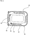
- FIG. 3 is a view showing a shape of a suspension used in the conventional micro speaker.
- a circular voice coil 10 is changed to a rectangular voice coil 20 using a jig 30.
- lead wires 22 and 24 of the voice coil 20 are positioned on the short side of the rectangular shape.
- a suspension 40 includes an outer peripheral portion 42, an inner peripheral portion 46, and a connection portion 44 connecting the outer peripheral portion 42 to the inner peripheral portion 46.
- a conductive pattern 50 as well as land portions 60 for use in soldering or bonding the lead wires 22 and 24 of the voice coil 20 are formed on the surface of the suspension 40.
- the land portions 60 for use in soldering or bonding the lead wires 22 and 24 of the voice coil 20 are formed on the connection portion 44 disposed on the short side adjacent to the positions of the lead wires 22 and 24 of the coil.
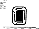
- FIG. 4 is a view showing stress distribution of each portion that is generated in the event of vibration of the conventional suspension.
- WO 2011/027995 A2 discloses a microspeaker comprising: a frame having a hollow interior; a cover for covering one open side of the frame; a yoke for covering the other open side of the frame; an external magnet inserted into the frame and having a hollow interior, and which generates a magnetic field having a predetermined intensity and direction; an external plate for concentrating, in a specific direction, the magnetic field generated by the external magnet; an internal magnet for generating a magnetic field in a direction identical to that of the magnetic field of the external magnet; and an internal plate mounted on an upper surface of the internal magnet to concentrate, in a specific direction, the magnetic field generated by the internal magnet. Further, a voice coil is arranged to vibrate in the height direction of the external magnet and internal magnet.
- a vibrating body is arranged to vibrate along with the voice coil in the upward and downward directions.
- a vibrating diaphragm is interposed between the cover and the vibrating body so as to vibrate in the upward and downward directions by means of the vibrating body which vibrates in the upward and downward directions, in order to generate sound.
- a solder pad is mounted on the vibrating body to transmit an electrical control signal transmitted from the outside of the frame to the vibrating body.
- An object of the present invention is to provide a suspension structure which can resist high power in a micro speaker.
- Another object of the present invention is to provide a conductive pattern of a suspension for a micro speaker which can transmit electric signals even when cracks occur in some part of the suspension.
- a further object of the present invention is to provide a shape of a suspension and a conductive pattern which can minimize a further decrease in sound pressure caused by the use of the suspension.
- a still further object of the present invention is to provide a suspension which does not interrupt a smooth vertical movement of a diaphragm.
- FIG. 5 is a view showing a voice coil lead-in wire structure provided in a high power micro speaker according the present invention.
- a voice coil 100 provided in the high power micro speaker according to the present invention is formed in a rectangular shape like a conventional rectangular coil 10.
- the voice coil 100 provided in the high power micro speaker of the present invention and the voice coil 10 of the prior art have a difference in drawing-out directions of lead wires 120 and 140.
- the lead wires 120 and 140 of the voice coil 100 are not disposed on the same side of the rectangular shape side by side but drawn out from opposite diagonal sides.
- the lead wires 120 and 140 are drawn out from ends of two longer sides among the four sides of the rectangle.
- the lead wires 120 and 140 of the voice coil 100 are shaped in a right-angle direction according to a shape of a connection portion of the suspension discussed later.
- FIG. 6 is a view showing the suspension for the high power micro speaker according to the present invention.
- a suspension 200 according to the present invention includes an outer peripheral portion 210, connection portions 220' and 220" and a central portion 230, and also includes a terminal portion 240 for providing electric connection to an external terminal on one side.
- a conductive pattern 250 is formed on the suspension 200, in particular, on the outer peripheral portion 210, the terminal portion 240 on one side of the outer peripheral portion 210, and the connection portions 220' and 220".
- the suspension 200 is formed in a rectangular shape, and land portions 260 for use in welding or soldering the lead wires 120 and 140 of the voice coil 100 are disposed on the connection portions 220' (longer sides of the rectangle) connecting the outer peripheral portion 210 to the central portion 230 among the connection portions 220' and 220". That is, the land portions 260 for use in welding or soldering the lead wires 120 and 140 are symmetrically positioned in a diagonal direction.
- the land portions 260 for use in welding or soldering the lead wires 120 and 140 of the voice coil 100 are disposed on the longer connection portions 220' among the connection portions 220' and 220", which prevents cracks from occurring in the conductive pattern 250 in high power, and the land portions 260 are symmetrically positioned, which prevents unbalanced vibration.
- FIG. 7 is a view showing the position, from which a protective film is removed, on the suspension for the high power micro speaker according to the present invention.
- Protective films 310, 320 and 330 for protecting the conductive pattern 250 formed on the suspension 200 as well as the suspension 200 itself are attached to the top and bottom of the suspension for the high power micro speaker according to one embodiment of the present invention.
- the protective films 310, 320 and 330 are attached to the outer peripheral portion 210, the connection portions 220' and 220", and the central portion 230 of the suspension 200.
- Some sections 320', 320" and 330' of the protective films 310, 320 and 330 attached to the top of the suspension 200 (where the voice coil 100 is not attached) are removed to improve sound characteristics of the high power micro speaker.
- the sections 320', 320" and 330', from which the protective films are removed, are designated as shaded sections in FIG. 7 .
- the protective films 320 attached to the longer connection portions 220' disposed on the long sides among the connection portions 220' and 220" of the suspension 200 are partially or wholly removed (320') to reduce the intensity of vertical vibration, which facilitates low sound vibration when the speaker is mounted.
- the protective films 320 attached to the connection portions 220" disposed on the short sides among the connection portions 220' and 220" of the suspension 200 are partially removed (320") to reduce the intensity of vertical vibration, which facilitates low sound vibration when the speaker is mounted.
- the central portion of the protective film 330 attached to the central portion 230 of the suspension 200 is partially removed (330') to reduce a weight of the entire suspension 200, which improves a sound pressure.
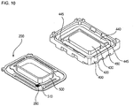
- FIGS. 8 to 10 are views showing a micro speaker according to a further example.
- some parts of a top plate corresponding to solder land portions are removed to prevent a suspension from colliding against the top surface of the top plate and thus getting damaged due to its excess vibration caused by high power vibration.
Landscapes
- Engineering & Computer Science (AREA)
- Physics & Mathematics (AREA)
- Acoustics & Sound (AREA)
- Signal Processing (AREA)
- Multimedia (AREA)
- Audible-Bandwidth Dynamoelectric Transducers Other Than Pickups (AREA)
Description
- The present invention relates to a suspension structure for a high power micro speaker and, more particularly, to a shape of a suspension which ensures a lightweight of the suspension as well as high reliability and a conductive pattern which applies electric signals.
- Sound reproduction techniques of mobile multimedia have been improved with the development of mobile communication technologies, as a result of which high performance, high sound quality and high power are required of a micro speaker.
- In most cases, a conventional micro speaker does not use a special suspension to ensure a lightweight of a diaphragm and connects a lead wire of a voice coil to the diaphragm via bonding to apply external electric signals to the voice coil. Therefore, unbalanced vibration is often generated due to the absence of the suspension, and the lead wire of the coil is often down in high power due to a tensile force, which makes it difficult for the micro speaker to be applied to high power.
- In order to solve the foregoing problem, there has been developed a micro speaker using a suspension provided with a conductive pattern for transmitting electric signals. In the case of the micro speaker using the suspension, an increase in weight of the diaphragm, which results from the use of the suspension, leads to a decrease in sound pressure of the micro speaker. In addition, cracks may occur in the conductive pattern in high power, causing a defect.
-
FIG. 1 is a view showing a shape of a voice coil and a lead wire used in a conventional suspension type micro speaker,FIG. 2 is a view showing fabrication of a rectangular coil ofFIG. 1 , andFIG. 3 is a view showing a shape of a suspension used in the conventional micro speaker. As illustrated inFIG. 2 , acircular voice coil 10 is changed to arectangular voice coil 20 using ajig 30. Here,lead wires 22 and 24 of thevoice coil 20 are positioned on the short side of the rectangular shape. Referring toFIG. 3 , asuspension 40 includes an outerperipheral portion 42, an innerperipheral portion 46, and aconnection portion 44 connecting the outerperipheral portion 42 to the innerperipheral portion 46. Aconductive pattern 50 as well asland portions 60 for use in soldering or bonding thelead wires 22 and 24 of thevoice coil 20 are formed on the surface of thesuspension 40. In theconventional suspension 40, theland portions 60 for use in soldering or bonding thelead wires 22 and 24 of thevoice coil 20 are formed on theconnection portion 44 disposed on the short side adjacent to the positions of thelead wires 22 and 24 of the coil. -
FIG. 4 is a view showing stress distribution of each portion that is generated in the event of vibration of the conventional suspension. - Here, it can be seen that a significant surface tension occurs inside the
short connection portion 44 disposed on the short side of thesuspension 40, as a result of which cracks may easily occur in theconductive pattern 50 formed on the surface of thesuspension 40. -
WO 2011/027995 A2 discloses a microspeaker comprising: a frame having a hollow interior; a cover for covering one open side of the frame; a yoke for covering the other open side of the frame; an external magnet inserted into the frame and having a hollow interior, and which generates a magnetic field having a predetermined intensity and direction; an external plate for concentrating, in a specific direction, the magnetic field generated by the external magnet; an internal magnet for generating a magnetic field in a direction identical to that of the magnetic field of the external magnet; and an internal plate mounted on an upper surface of the internal magnet to concentrate, in a specific direction, the magnetic field generated by the internal magnet. Further, a voice coil is arranged to vibrate in the height direction of the external magnet and internal magnet. A vibrating body is arranged to vibrate along with the voice coil in the upward and downward directions. A vibrating diaphragm is interposed between the cover and the vibrating body so as to vibrate in the upward and downward directions by means of the vibrating body which vibrates in the upward and downward directions, in order to generate sound. A solder pad is mounted on the vibrating body to transmit an electrical control signal transmitted from the outside of the frame to the vibrating body. The thus-configured microspeaker having a high output vibrating diaphragm joining structure prevents the disconnection of both ends of the voice coil coupled to the vibrating body, improves the vibrating strength of the vibrating diaphragm, and thus achieves a higher sound output. - An object of the present invention is to provide a suspension structure which can resist high power in a micro speaker.
- Another object of the present invention is to provide a conductive pattern of a suspension for a micro speaker which can transmit electric signals even when cracks occur in some part of the suspension.
- A further object of the present invention is to provide a shape of a suspension and a conductive pattern which can minimize a further decrease in sound pressure caused by the use of the suspension.
- A still further object of the present invention is to provide a suspension which does not interrupt a smooth vertical movement of a diaphragm.
- These objects are solved by the subject-matter of the claims.
-
-
FIG. 1 is a view showing a shape of a voice coil and a lead wire used in a conventional micro speaker having a suspension. -
FIG. 2 is a view showing fabrication of a rectangular coil ofFIG. 1 . -
FIG. 3 is a view showing the suspension used in the conventional micro speaker. -
FIG. 4 is a view showing stress distribution of each portion that is generated in the event of vibration of the conventional suspension. -
FIG. 5 is a view showing a voice coil lead-in wire structure provided in a micro speaker according to a first embodiment of the present invention. -
FIG. 6 is a view showing positions of land portions of a suspension for the high power micro speaker according to the present invention. -
FIG. 7 is a view showing the position, from which a protective film is removed, on the suspension for the high power micro speaker according to the present invention. -
FIGS. 8 to 10 are views showing a high power micro speaker according to further examples. - Hereinafter, preferred embodiments of the present invention will be described in detail with reference to the accompanying drawings.
-
FIG. 5 is a view showing a voice coil lead-in wire structure provided in a high power micro speaker according the present invention. Avoice coil 100 provided in the high power micro speaker according to the present invention is formed in a rectangular shape like a conventionalrectangular coil 10. However, thevoice coil 100 provided in the high power micro speaker of the present invention and thevoice coil 10 of the prior art have a difference in drawing-out directions oflead wires lead wires voice coil 100 are not disposed on the same side of the rectangular shape side by side but drawn out from opposite diagonal sides. Preferably, thelead wires lead wires lead wires voice coil 100 are shaped in a right-angle direction according to a shape of a connection portion of the suspension discussed later. -
FIG. 6 is a view showing the suspension for the high power micro speaker according to the present invention. Asuspension 200 according to the present invention includes an outerperipheral portion 210,connection portions 220' and 220" and acentral portion 230, and also includes aterminal portion 240 for providing electric connection to an external terminal on one side. In addition, aconductive pattern 250 is formed on thesuspension 200, in particular, on the outerperipheral portion 210, theterminal portion 240 on one side of the outerperipheral portion 210, and theconnection portions 220' and 220". Meanwhile, thesuspension 200 is formed in a rectangular shape, andland portions 260 for use in welding or soldering thelead wires voice coil 100 are disposed on the connection portions 220' (longer sides of the rectangle) connecting the outerperipheral portion 210 to thecentral portion 230 among theconnection portions 220' and 220". That is, theland portions 260 for use in welding or soldering thelead wires land portions 260 for use in welding or soldering thelead wires voice coil 100 are disposed on the longer connection portions 220' among theconnection portions 220' and 220", which prevents cracks from occurring in theconductive pattern 250 in high power, and theland portions 260 are symmetrically positioned, which prevents unbalanced vibration. -
FIG. 7 is a view showing the position, from which a protective film is removed, on the suspension for the high power micro speaker according to the present invention.Protective films conductive pattern 250 formed on thesuspension 200 as well as thesuspension 200 itself are attached to the top and bottom of the suspension for the high power micro speaker according to one embodiment of the present invention. Theprotective films peripheral portion 210, theconnection portions 220' and 220", and thecentral portion 230 of thesuspension 200. Somesections 320', 320" and 330' of theprotective films voice coil 100 is not attached) are removed to improve sound characteristics of the high power micro speaker. Thesections 320', 320" and 330', from which the protective films are removed, are designated as shaded sections inFIG. 7 . - In particular, the
protective films 320 attached to the longer connection portions 220' disposed on the long sides among theconnection portions 220' and 220" of thesuspension 200 are partially or wholly removed (320') to reduce the intensity of vertical vibration, which facilitates low sound vibration when the speaker is mounted. - Additionally, according to an embodiment of the present invention, the
protective films 320 attached to theconnection portions 220" disposed on the short sides among theconnection portions 220' and 220" of thesuspension 200 are partially removed (320") to reduce the intensity of vertical vibration, which facilitates low sound vibration when the speaker is mounted. - Moreover, according to an embodiment of the present invention, the central portion of the
protective film 330 attached to thecentral portion 230 of thesuspension 200 is partially removed (330') to reduce a weight of theentire suspension 200, which improves a sound pressure. -
FIGS. 8 to 10 are views showing a micro speaker according to a further example. In the micro speaker according to this example, some parts of a top plate corresponding to solder land portions are removed to prevent a suspension from colliding against the top surface of the top plate and thus getting damaged due to its excess vibration caused by high power vibration.
Claims (3)
- A suspension (200) for a high power micro speaker that includes an outer peripheral portion (210), a central portion (230) and connection portions (220', 220"), the suspension (200) being provided with a conductive pattern (250), and the outer peripheral portion (210) and the central portion being (230) formed in a rectangular shape,
wherein the connection portions (220', 220") comprise a pair of long connection portions (220') connecting long sides of the outer peripheral portion (210) and the central portion (230) and a pair of short connection portions (220") connecting short sides of the outer peripheral portion (210) and the central portion (230),
wherein land portions (260) for use in soldering or welding lead-in wires (120, 140) of a voice coil (100) are formed on the long connection portions (220'),
wherein the suspension further comprises a protective film (310, 320, 330) for protecting the conductive pattern (250), which protective film (310, 320, 330) is attached to the outer peripheral portion (210), at least a part of the central portion (230) and at least a part of the connection portions (220', 220"), characterized in that
the protective film (310, 320, 330) is not attached to parts of the long connection portions (220') disposed on the long sides, or is not attached to the long connection portions (220'). - The suspension (200) of claim 1, wherein the protective film (310, 320, 330) is not attached to a part of the central portion (230).
- The suspension (200) of claim 1, wherein the protective film (310, 320, 330) is not attached to parts of the short connection portions (220").
Priority Applications (1)
| Application Number | Priority Date | Filing Date | Title |
|---|---|---|---|
| EP12006042.1A EP2701402B1 (en) | 2012-08-24 | 2012-08-24 | Suspension for high power micro speaker, and high power micro speaker having the same |
Applications Claiming Priority (1)
| Application Number | Priority Date | Filing Date | Title |
|---|---|---|---|
| EP12006042.1A EP2701402B1 (en) | 2012-08-24 | 2012-08-24 | Suspension for high power micro speaker, and high power micro speaker having the same |
Publications (2)
| Publication Number | Publication Date |
|---|---|
| EP2701402A1 EP2701402A1 (en) | 2014-02-26 |
| EP2701402B1 true EP2701402B1 (en) | 2019-11-13 |
Family
ID=46875624
Family Applications (1)
| Application Number | Title | Priority Date | Filing Date |
|---|---|---|---|
| EP12006042.1A Active EP2701402B1 (en) | 2012-08-24 | 2012-08-24 | Suspension for high power micro speaker, and high power micro speaker having the same |
Country Status (1)
| Country | Link |
|---|---|
| EP (1) | EP2701402B1 (en) |
Citations (2)
| Publication number | Priority date | Publication date | Assignee | Title |
|---|---|---|---|---|
| WO2012023775A1 (en) * | 2010-08-17 | 2012-02-23 | 주식회사 엑셀웨이 | Vibration-lead plate for flat type speaker, mounted between voice coil plate and vibration plate |
| EP2490461A2 (en) * | 2010-08-18 | 2012-08-22 | Em-tech. Co., Ltd. | Acoustic transducer device |
Family Cites Families (3)
| Publication number | Priority date | Publication date | Assignee | Title |
|---|---|---|---|---|
| KR100930537B1 (en) * | 2009-09-03 | 2009-12-09 | 주식회사 블루콤 | Micro speaker with high power diaphragm mating structure |
| KR20110022656A (en) * | 2011-02-16 | 2011-03-07 | 박태복 | High power micro speakers |
| KR101187510B1 (en) * | 2011-12-14 | 2012-10-02 | 부전전자 주식회사 | High power micro-speaker |
-
2012
- 2012-08-24 EP EP12006042.1A patent/EP2701402B1/en active Active
Patent Citations (3)
| Publication number | Priority date | Publication date | Assignee | Title |
|---|---|---|---|---|
| WO2012023775A1 (en) * | 2010-08-17 | 2012-02-23 | 주식회사 엑셀웨이 | Vibration-lead plate for flat type speaker, mounted between voice coil plate and vibration plate |
| EP2608571A1 (en) * | 2010-08-17 | 2013-06-26 | Exelway Inc. | Vibration-lead plate for flat type speaker, mounted between voice coil plate and vibration plate |
| EP2490461A2 (en) * | 2010-08-18 | 2012-08-22 | Em-tech. Co., Ltd. | Acoustic transducer device |
Also Published As
| Publication number | Publication date |
|---|---|
| EP2701402A1 (en) | 2014-02-26 |
Similar Documents
| Publication | Publication Date | Title |
|---|---|---|
| US9900703B2 (en) | Suspension for high power micro speaker and high power micro speaker having the same | |
| CN102598709B (en) | Acoustic transducer device | |
| EP2709381B1 (en) | High output micro speaker | |
| EP2770752A2 (en) | Inner ring magnet type microspeaker | |
| CN101583068A (en) | Electroacoustic transducing device | |
| CN110662155B (en) | Sound production device and assembly method thereof | |
| KR101439915B1 (en) | Slim width microspeaker | |
| EP2725820B1 (en) | Vibration module for sound transducer | |
| WO2019205659A1 (en) | Sound producing device, sound producing module, and electronic terminal | |
| EP2809080B1 (en) | Microspeaker with improved soldering structure | |
| KR101351893B1 (en) | Suspension for high power micro speaker and high power micro speaker having the same | |
| KR101381255B1 (en) | Hybrid microspeaker | |
| US20160234586A1 (en) | Electroacoustic transducer | |
| US10104476B2 (en) | Miniature loudspeaker | |
| CN214177561U (en) | Sound producing device | |
| KR101255586B1 (en) | High power acoustic transducer | |
| CN103686549B (en) | The suspension of high power micro-speaker and the high power micro-speaker with suspension | |
| KR101148055B1 (en) | Sound transducer having spring member which can conduct electiric signals and be used as a suspension | |
| CN202551344U (en) | Bone-conduction microphone | |
| CN204887427U (en) | a speaker | |
| US20110293132A1 (en) | Electroacoustic transducer | |
| KR20130004464A (en) | High power acoustic transducer | |
| KR101498454B1 (en) | Speaker | |
| KR101142254B1 (en) | High power rectangular speaker having suspension | |
| EP2701402A1 (en) | Suspension for high power micro speaker, and high power micro speaker having the same |
Legal Events
| Date | Code | Title | Description |
|---|---|---|---|
| PUAI | Public reference made under article 153(3) epc to a published international application that has entered the european phase |
Free format text: ORIGINAL CODE: 0009012 |
|
| AK | Designated contracting states |
Kind code of ref document: A1 Designated state(s): AL AT BE BG CH CY CZ DE DK EE ES FI FR GB GR HR HU IE IS IT LI LT LU LV MC MK MT NL NO PL PT RO RS SE SI SK SM TR |
|
| AX | Request for extension of the european patent |
Extension state: BA ME |
|
| 17P | Request for examination filed |
Effective date: 20140728 |
|
| RBV | Designated contracting states (corrected) |
Designated state(s): AL AT BE BG CH CY CZ DE DK EE ES FI FR GB GR HR HU IE IS IT LI LT LU LV MC MK MT NL NO PL PT RO RS SE SI SK SM TR |
|
| STAA | Information on the status of an ep patent application or granted ep patent |
Free format text: STATUS: EXAMINATION IS IN PROGRESS |
|
| 17Q | First examination report despatched |
Effective date: 20180426 |
|
| GRAP | Despatch of communication of intention to grant a patent |
Free format text: ORIGINAL CODE: EPIDOSNIGR1 |
|
| STAA | Information on the status of an ep patent application or granted ep patent |
Free format text: STATUS: GRANT OF PATENT IS INTENDED |
|
| INTG | Intention to grant announced |
Effective date: 20190607 |
|
| RIN1 | Information on inventor provided before grant (corrected) |
Inventor name: JEONG, IN HO Inventor name: CHOI, KYU DONG Inventor name: KIM, CHEON MYEONG |
|
| GRAS | Grant fee paid |
Free format text: ORIGINAL CODE: EPIDOSNIGR3 |
|
| GRAA | (expected) grant |
Free format text: ORIGINAL CODE: 0009210 |
|
| STAA | Information on the status of an ep patent application or granted ep patent |
Free format text: STATUS: THE PATENT HAS BEEN GRANTED |
|
| AK | Designated contracting states |
Kind code of ref document: B1 Designated state(s): AL AT BE BG CH CY CZ DE DK EE ES FI FR GB GR HR HU IE IS IT LI LT LU LV MC MK MT NL NO PL PT RO RS SE SI SK SM TR |
|
| REG | Reference to a national code |
Ref country code: CH Ref legal event code: EP Ref country code: AT Ref legal event code: REF Ref document number: 1202940 Country of ref document: AT Kind code of ref document: T Effective date: 20191115 |
|
| REG | Reference to a national code |
Ref country code: DE Ref legal event code: R096 Ref document number: 602012065586 Country of ref document: DE |
|
| REG | Reference to a national code |
Ref country code: IE Ref legal event code: FG4D |
|
| REG | Reference to a national code |
Ref country code: NL Ref legal event code: MP Effective date: 20191113 |
|
| REG | Reference to a national code |
Ref country code: LT Ref legal event code: MG4D |
|
| PG25 | Lapsed in a contracting state [announced via postgrant information from national office to epo] |
Ref country code: ES Free format text: LAPSE BECAUSE OF FAILURE TO SUBMIT A TRANSLATION OF THE DESCRIPTION OR TO PAY THE FEE WITHIN THE PRESCRIBED TIME-LIMIT Effective date: 20191113 Ref country code: PT Free format text: LAPSE BECAUSE OF FAILURE TO SUBMIT A TRANSLATION OF THE DESCRIPTION OR TO PAY THE FEE WITHIN THE PRESCRIBED TIME-LIMIT Effective date: 20200313 Ref country code: SE Free format text: LAPSE BECAUSE OF FAILURE TO SUBMIT A TRANSLATION OF THE DESCRIPTION OR TO PAY THE FEE WITHIN THE PRESCRIBED TIME-LIMIT Effective date: 20191113 Ref country code: LV Free format text: LAPSE BECAUSE OF FAILURE TO SUBMIT A TRANSLATION OF THE DESCRIPTION OR TO PAY THE FEE WITHIN THE PRESCRIBED TIME-LIMIT Effective date: 20191113 Ref country code: NL Free format text: LAPSE BECAUSE OF FAILURE TO SUBMIT A TRANSLATION OF THE DESCRIPTION OR TO PAY THE FEE WITHIN THE PRESCRIBED TIME-LIMIT Effective date: 20191113 Ref country code: PL Free format text: LAPSE BECAUSE OF FAILURE TO SUBMIT A TRANSLATION OF THE DESCRIPTION OR TO PAY THE FEE WITHIN THE PRESCRIBED TIME-LIMIT Effective date: 20191113 Ref country code: LT Free format text: LAPSE BECAUSE OF FAILURE TO SUBMIT A TRANSLATION OF THE DESCRIPTION OR TO PAY THE FEE WITHIN THE PRESCRIBED TIME-LIMIT Effective date: 20191113 Ref country code: BG Free format text: LAPSE BECAUSE OF FAILURE TO SUBMIT A TRANSLATION OF THE DESCRIPTION OR TO PAY THE FEE WITHIN THE PRESCRIBED TIME-LIMIT Effective date: 20200213 Ref country code: GR Free format text: LAPSE BECAUSE OF FAILURE TO SUBMIT A TRANSLATION OF THE DESCRIPTION OR TO PAY THE FEE WITHIN THE PRESCRIBED TIME-LIMIT Effective date: 20200214 Ref country code: NO Free format text: LAPSE BECAUSE OF FAILURE TO SUBMIT A TRANSLATION OF THE DESCRIPTION OR TO PAY THE FEE WITHIN THE PRESCRIBED TIME-LIMIT Effective date: 20200213 Ref country code: FI Free format text: LAPSE BECAUSE OF FAILURE TO SUBMIT A TRANSLATION OF THE DESCRIPTION OR TO PAY THE FEE WITHIN THE PRESCRIBED TIME-LIMIT Effective date: 20191113 |
|
| PG25 | Lapsed in a contracting state [announced via postgrant information from national office to epo] |
Ref country code: RS Free format text: LAPSE BECAUSE OF FAILURE TO SUBMIT A TRANSLATION OF THE DESCRIPTION OR TO PAY THE FEE WITHIN THE PRESCRIBED TIME-LIMIT Effective date: 20191113 Ref country code: IS Free format text: LAPSE BECAUSE OF FAILURE TO SUBMIT A TRANSLATION OF THE DESCRIPTION OR TO PAY THE FEE WITHIN THE PRESCRIBED TIME-LIMIT Effective date: 20200313 Ref country code: HR Free format text: LAPSE BECAUSE OF FAILURE TO SUBMIT A TRANSLATION OF THE DESCRIPTION OR TO PAY THE FEE WITHIN THE PRESCRIBED TIME-LIMIT Effective date: 20191113 |
|
| PG25 | Lapsed in a contracting state [announced via postgrant information from national office to epo] |
Ref country code: AL Free format text: LAPSE BECAUSE OF FAILURE TO SUBMIT A TRANSLATION OF THE DESCRIPTION OR TO PAY THE FEE WITHIN THE PRESCRIBED TIME-LIMIT Effective date: 20191113 |
|
| PG25 | Lapsed in a contracting state [announced via postgrant information from national office to epo] |
Ref country code: EE Free format text: LAPSE BECAUSE OF FAILURE TO SUBMIT A TRANSLATION OF THE DESCRIPTION OR TO PAY THE FEE WITHIN THE PRESCRIBED TIME-LIMIT Effective date: 20191113 Ref country code: DK Free format text: LAPSE BECAUSE OF FAILURE TO SUBMIT A TRANSLATION OF THE DESCRIPTION OR TO PAY THE FEE WITHIN THE PRESCRIBED TIME-LIMIT Effective date: 20191113 Ref country code: RO Free format text: LAPSE BECAUSE OF FAILURE TO SUBMIT A TRANSLATION OF THE DESCRIPTION OR TO PAY THE FEE WITHIN THE PRESCRIBED TIME-LIMIT Effective date: 20191113 Ref country code: CZ Free format text: LAPSE BECAUSE OF FAILURE TO SUBMIT A TRANSLATION OF THE DESCRIPTION OR TO PAY THE FEE WITHIN THE PRESCRIBED TIME-LIMIT Effective date: 20191113 |
|
| REG | Reference to a national code |
Ref country code: DE Ref legal event code: R097 Ref document number: 602012065586 Country of ref document: DE |
|
| REG | Reference to a national code |
Ref country code: AT Ref legal event code: MK05 Ref document number: 1202940 Country of ref document: AT Kind code of ref document: T Effective date: 20191113 |
|
| PG25 | Lapsed in a contracting state [announced via postgrant information from national office to epo] |
Ref country code: SM Free format text: LAPSE BECAUSE OF FAILURE TO SUBMIT A TRANSLATION OF THE DESCRIPTION OR TO PAY THE FEE WITHIN THE PRESCRIBED TIME-LIMIT Effective date: 20191113 Ref country code: SK Free format text: LAPSE BECAUSE OF FAILURE TO SUBMIT A TRANSLATION OF THE DESCRIPTION OR TO PAY THE FEE WITHIN THE PRESCRIBED TIME-LIMIT Effective date: 20191113 |
|
| PLBE | No opposition filed within time limit |
Free format text: ORIGINAL CODE: 0009261 |
|
| STAA | Information on the status of an ep patent application or granted ep patent |
Free format text: STATUS: NO OPPOSITION FILED WITHIN TIME LIMIT |
|
| 26N | No opposition filed |
Effective date: 20200814 |
|
| PG25 | Lapsed in a contracting state [announced via postgrant information from national office to epo] |
Ref country code: SI Free format text: LAPSE BECAUSE OF FAILURE TO SUBMIT A TRANSLATION OF THE DESCRIPTION OR TO PAY THE FEE WITHIN THE PRESCRIBED TIME-LIMIT Effective date: 20191113 Ref country code: AT Free format text: LAPSE BECAUSE OF FAILURE TO SUBMIT A TRANSLATION OF THE DESCRIPTION OR TO PAY THE FEE WITHIN THE PRESCRIBED TIME-LIMIT Effective date: 20191113 |
|
| PG25 | Lapsed in a contracting state [announced via postgrant information from national office to epo] |
Ref country code: IT Free format text: LAPSE BECAUSE OF FAILURE TO SUBMIT A TRANSLATION OF THE DESCRIPTION OR TO PAY THE FEE WITHIN THE PRESCRIBED TIME-LIMIT Effective date: 20191113 |
|
| PG25 | Lapsed in a contracting state [announced via postgrant information from national office to epo] |
Ref country code: MC Free format text: LAPSE BECAUSE OF FAILURE TO SUBMIT A TRANSLATION OF THE DESCRIPTION OR TO PAY THE FEE WITHIN THE PRESCRIBED TIME-LIMIT Effective date: 20191113 |
|
| REG | Reference to a national code |
Ref country code: CH Ref legal event code: PL |
|
| GBPC | Gb: european patent ceased through non-payment of renewal fee |
Effective date: 20200824 |
|
| PG25 | Lapsed in a contracting state [announced via postgrant information from national office to epo] |
Ref country code: LI Free format text: LAPSE BECAUSE OF NON-PAYMENT OF DUE FEES Effective date: 20200831 Ref country code: CH Free format text: LAPSE BECAUSE OF NON-PAYMENT OF DUE FEES Effective date: 20200831 Ref country code: LU Free format text: LAPSE BECAUSE OF NON-PAYMENT OF DUE FEES Effective date: 20200824 |
|
| REG | Reference to a national code |
Ref country code: BE Ref legal event code: MM Effective date: 20200831 |
|
| PG25 | Lapsed in a contracting state [announced via postgrant information from national office to epo] |
Ref country code: FR Free format text: LAPSE BECAUSE OF NON-PAYMENT OF DUE FEES Effective date: 20200831 |
|
| PG25 | Lapsed in a contracting state [announced via postgrant information from national office to epo] |
Ref country code: BE Free format text: LAPSE BECAUSE OF NON-PAYMENT OF DUE FEES Effective date: 20200831 Ref country code: IE Free format text: LAPSE BECAUSE OF NON-PAYMENT OF DUE FEES Effective date: 20200824 Ref country code: GB Free format text: LAPSE BECAUSE OF NON-PAYMENT OF DUE FEES Effective date: 20200824 |
|
| PGFP | Annual fee paid to national office [announced via postgrant information from national office to epo] |
Ref country code: DE Payment date: 20210827 Year of fee payment: 10 |
|
| PG25 | Lapsed in a contracting state [announced via postgrant information from national office to epo] |
Ref country code: TR Free format text: LAPSE BECAUSE OF FAILURE TO SUBMIT A TRANSLATION OF THE DESCRIPTION OR TO PAY THE FEE WITHIN THE PRESCRIBED TIME-LIMIT Effective date: 20191113 Ref country code: MT Free format text: LAPSE BECAUSE OF FAILURE TO SUBMIT A TRANSLATION OF THE DESCRIPTION OR TO PAY THE FEE WITHIN THE PRESCRIBED TIME-LIMIT Effective date: 20191113 Ref country code: CY Free format text: LAPSE BECAUSE OF FAILURE TO SUBMIT A TRANSLATION OF THE DESCRIPTION OR TO PAY THE FEE WITHIN THE PRESCRIBED TIME-LIMIT Effective date: 20191113 |
|
| PG25 | Lapsed in a contracting state [announced via postgrant information from national office to epo] |
Ref country code: MK Free format text: LAPSE BECAUSE OF FAILURE TO SUBMIT A TRANSLATION OF THE DESCRIPTION OR TO PAY THE FEE WITHIN THE PRESCRIBED TIME-LIMIT Effective date: 20191113 |
|
| REG | Reference to a national code |
Ref country code: DE Ref legal event code: R119 Ref document number: 602012065586 Country of ref document: DE |
|
| PG25 | Lapsed in a contracting state [announced via postgrant information from national office to epo] |
Ref country code: DE Free format text: LAPSE BECAUSE OF NON-PAYMENT OF DUE FEES Effective date: 20230301 |