EP2701320B1 - Verfahren zur übertragung von steuerungsinformationen in einem drahtlosen kommunikationssystem und vorrichtung dafür - Google Patents
Verfahren zur übertragung von steuerungsinformationen in einem drahtlosen kommunikationssystem und vorrichtung dafür Download PDFInfo
- Publication number
- EP2701320B1 EP2701320B1 EP12773941.5A EP12773941A EP2701320B1 EP 2701320 B1 EP2701320 B1 EP 2701320B1 EP 12773941 A EP12773941 A EP 12773941A EP 2701320 B1 EP2701320 B1 EP 2701320B1
- Authority
- EP
- European Patent Office
- Prior art keywords
- information
- pusch
- slot
- pucch
- transmission
- Prior art date
- Legal status (The legal status is an assumption and is not a legal conclusion. Google has not performed a legal analysis and makes no representation as to the accuracy of the status listed.)
- Active
Links
- 238000000034 method Methods 0.000 title claims description 59
- 238000004891 communication Methods 0.000 title claims description 29
- 230000005540 biological transmission Effects 0.000 claims description 192
- 108010003272 Hyaluronate lyase Proteins 0.000 description 177
- 101000741965 Homo sapiens Inactive tyrosine-protein kinase PRAG1 Proteins 0.000 description 61
- 102100038659 Inactive tyrosine-protein kinase PRAG1 Human genes 0.000 description 61
- 102100036409 Activated CDC42 kinase 1 Human genes 0.000 description 58
- 239000000969 carrier Substances 0.000 description 36
- 230000004913 activation Effects 0.000 description 21
- 238000012545 processing Methods 0.000 description 20
- 230000015654 memory Effects 0.000 description 18
- 238000013507 mapping Methods 0.000 description 16
- 230000007480 spreading Effects 0.000 description 14
- 230000006870 function Effects 0.000 description 10
- 230000002776 aggregation Effects 0.000 description 8
- 238000004220 aggregation Methods 0.000 description 8
- 125000004122 cyclic group Chemical group 0.000 description 4
- 238000010586 diagram Methods 0.000 description 4
- 241000760358 Enodes Species 0.000 description 3
- 230000000694 effects Effects 0.000 description 3
- 238000005516 engineering process Methods 0.000 description 3
- 230000008054 signal transmission Effects 0.000 description 3
- 230000011664 signaling Effects 0.000 description 3
- 238000003491 array Methods 0.000 description 2
- 239000000872 buffer Substances 0.000 description 2
- 238000010276 construction Methods 0.000 description 2
- 230000003247 decreasing effect Effects 0.000 description 2
- 239000011159 matrix material Substances 0.000 description 2
- 238000012986 modification Methods 0.000 description 2
- 230000004048 modification Effects 0.000 description 2
- 230000010363 phase shift Effects 0.000 description 2
- 238000003672 processing method Methods 0.000 description 2
- 229920006934 PMI Polymers 0.000 description 1
- 101150071746 Pbsn gene Proteins 0.000 description 1
- 102100035362 Phosphomannomutase 2 Human genes 0.000 description 1
- 230000004931 aggregating effect Effects 0.000 description 1
- 238000013459 approach Methods 0.000 description 1
- 238000006243 chemical reaction Methods 0.000 description 1
- 230000001419 dependent effect Effects 0.000 description 1
- 238000013461 design Methods 0.000 description 1
- 230000007774 longterm Effects 0.000 description 1
- 238000007726 management method Methods 0.000 description 1
- 238000010295 mobile communication Methods 0.000 description 1
- 230000003287 optical effect Effects 0.000 description 1
- 230000000737 periodic effect Effects 0.000 description 1
- 230000002085 persistent effect Effects 0.000 description 1
- 230000008569 process Effects 0.000 description 1
- 238000013468 resource allocation Methods 0.000 description 1
- 238000005070 sampling Methods 0.000 description 1
- 238000001228 spectrum Methods 0.000 description 1
- 230000003068 static effect Effects 0.000 description 1
- 239000002699 waste material Substances 0.000 description 1
Images


Classifications
-
- H—ELECTRICITY
- H04—ELECTRIC COMMUNICATION TECHNIQUE
- H04L—TRANSMISSION OF DIGITAL INFORMATION, e.g. TELEGRAPHIC COMMUNICATION
- H04L5/00—Arrangements affording multiple use of the transmission path
- H04L5/003—Arrangements for allocating sub-channels of the transmission path
- H04L5/0053—Allocation of signaling, i.e. of overhead other than pilot signals
-
- H—ELECTRICITY
- H04—ELECTRIC COMMUNICATION TECHNIQUE
- H04W—WIRELESS COMMUNICATION NETWORKS
- H04W36/00—Hand-off or reselection arrangements
- H04W36/08—Reselecting an access point
-
- H—ELECTRICITY
- H04—ELECTRIC COMMUNICATION TECHNIQUE
- H04W—WIRELESS COMMUNICATION NETWORKS
- H04W72/00—Local resource management
- H04W72/20—Control channels or signalling for resource management
-
- H—ELECTRICITY
- H04—ELECTRIC COMMUNICATION TECHNIQUE
- H04W—WIRELESS COMMUNICATION NETWORKS
- H04W72/00—Local resource management
- H04W72/20—Control channels or signalling for resource management
- H04W72/23—Control channels or signalling for resource management in the downlink direction of a wireless link, i.e. towards a terminal
Definitions
- the present invention relates to a wireless communication system, and more particularly, to a method and apparatus for transmitting control information.
- the wireless communication system may support Carrier Aggregation (CA).
- CA Carrier Aggregation
- a wireless communication system is a multiple access system that can support communication with multiple users by sharing available system resources (a bandwidth, transmission power, etc.) among the multiple users.
- Examples of the multiple access system include Code Division Multiple Access (CDMA), Frequency Division Multiple Access (FDMA), Time Division Multiple Access (TDMA), Orthogonal Frequency Division Multiple Access (OFDMA), Single Carrier Frequency Division Multiple Access (SC-FDMA), etc.
- WO 2011/041623 discloses methods and systems for transmitting uplink control information and feedback for carrier aggregation systems.
- a user equipment device is configured to transmit uplink control information and other feedback for several downlink component carriers using one or more uplink component carriers.
- the user equipment device transmits such data using a physical uplink control channel rather than a physical uplink shared channel.
- the user equipment device determines the uplink control information and feedback data that is to be transmitted, the physical uplink control channel resources to be used to transmit the uplink control information and feedback data, and how the uplink control information and feedback data may be transmitted over the physical uplink control channel.
- An object of the present invention devised to solve the conventional problem is to provide a method and apparatus for efficiently transmitting control information in a wireless communication system. Another object of the present invention is to provide a channel format, signal processing method, and apparatus for efficiently transmitting control information. Another object of the present invention is to provide a method and apparatus for efficiently allocating resources to transmit control information.
- a method for transmitting information to a Base Station (BS) at a User Equipment (UE) in a wireless communication system includes receiving first information for cross carrier scheduling from the BS in a primary cell among at least one serving cell configured for the UE, and transmitting second information about a secondary cell related to the first information among the at least one serving cell to the BS in an uplink resource of the primary cell.
- BS Base Station
- UE User Equipment
- the second information may include at least one of information indicating whether a Physical Uplink Shared CHannel (PUSCH) is transmitted in the secondary cell, information about a starting time of the PUSCH transmission, and information about an ending time of the PUSCH transmission.
- PUSCH Physical Uplink Shared CHannel
- the uplink resource of the primary cell may include a Physical Uplink Control CHannel (PUCCH) and a PUSCH.
- PUCCH Physical Uplink Control CHannel
- PUSCH Physical Uplink Control CHannel
- the second information may be one bit. If the second information indicates 0, the second information may indicate no Physical Uplink Shared CHannel (PUSCH) transmission in the secondary cell and if the second information indicates 1, the second information may indicate that the PUSCH is transmitted in the secondary cell, starting from the starting time of a corresponding slot.
- PUSCH Physical Uplink Shared CHannel
- the second information may be two bits and the second information may indicate whether a Physical Uplink Shared CHannel(PUSCH) is transmitted in the secondary cell, a starting time of the PUSCH transmission, and an ending time of the PUSCH transmission according to a combination of the two bits.
- PUSCH Physical Uplink Shared CHannel
- the ending time of the PUSCH transmission may be when a predetermined period for the PUSCH transmission ends after the starting time of the PUSCH transmission.
- the ending time of the PUSCH transmission may be a subframe boundary or a slot boundary of the primary cell, closest to the starting time of the PUSCH transmission.
- the method may further include transmitting state information about the secondary cell to the BS, and the state information may include the second information.
- the state information may indicate that a result of carrier sensing of the secondary cell is kept busy for a predetermined time or longer.
- a UE for transmitting information to a BS in a wireless communication system includes a processor, a reception module configured to receive first information for cross carrier scheduling from the BS in a primary cell among at least one serving cell configured for the UE, and a transmission module configured to transmit second information about a secondary cell related to the first information among the at least one serving cell to the BS in an uplink resource of the primary cell.
- the second information may include at least one of information indicating whether a Physical Uplink Shared CHannel(PUSCH) is transmitted in the secondary cell, information about a starting time of the PUSCH transmission, and information about an ending time of the PUSCH transmission.
- PUSCH Physical Uplink Shared CHannel
- the uplink resource of the primary cell may include a Physical Uplink Control CHannel(PUCCH) and a Physical Uplink Shared CHannel(PUSCH).
- PUCCH Physical Uplink Control CHannel
- PUSCH Physical Uplink Shared CHannel
- the second information may be one bit. If the second information indicates 0, the second information may indicate no PUSCH transmission in the secondary cell and if the second information indicates 1, the second information may indicate the PUSCH is transmitted in the secondary cell, starting from the starting time of a corresponding slot.
- the second information may be two bits, and the second information may indicate whether a Physical Uplink Shared CHannel(PUSCH) is to be transmitted in the secondary cell, a starting time of the PUSCH transmission, and an ending time of the PUSCH transmission according to a combination of the two bits.
- PUSCH Physical Uplink Shared CHannel
- the ending time of the PUSCH transmission may be when a predetermined period for the PUSCH transmission ends after the starting time of the PUSCH transmission.
- the ending time of the PUSCH transmission may be a subframe boundary or a slot boundary of the primary cell, closest to the starting time of the PUSCH transmission.
- the processor may control transmission of state information about the secondary cell to the BS through the transmission module, and the state information may include the second information.
- the state information may indicate that a result of carrier sensing of the secondary cell is kept busy for a predetermined time or longer.
- control information can be transmitted efficiently in a wireless communication system.
- a channel format and a signal processing method for efficiently transmitting control information can be provided.
- resources in which control information is transmitted can be efficiently allocated.
- CDMA Code Division Multiple Access
- FDMA Frequency Division Multiple Access
- TDMA Time Division Multiple Access
- OFDMA Orthogonal Frequency Division Multiple Access
- SC-FDMA Single Carrier Frequency Division Multiple Access
- MC-FDMA Multi-Carrier Frequency Division Multiple Access
- CDMA may be implemented as a radio technology such as Universal Terrestrial Radio Access (UTRA) or CDMA2000.
- TDMA may be implemented as a radio technology such as Global System for Mobile communications/General Packet Radio Service/Enhanced Data Rates for GSM Evolution (GSM/GPRS/EDGE).
- OFDMA may be implemented as a radio technology such as IEEE 802.11 (Wi-Fi), IEEE 802.16 (WiMAX), IEEE 802.20, Evolved-UTRA (E-UTRA) etc.
- UTRAN is a part of Universal Mobile Telecommunication System (UMTS).
- 3GPP 3 rd Generation Partnership Project
- LTE Long Term Evolution
- E-UMTS Evolved-UMTS
- 3GPP LTE employs OFDMA for Downlink (DL) and SC-FDMA for Uplink (UL).
- LTE-Advanced (LTE-A) is an evolution of 3GPP LTE. For clarity of description, the following description focuses on the 3GPP LTE/LTE-A system.
- a User Equipment is fixed or mobile.
- the UE is a device that transmits and receives user data and/or control information by communicating with a Base Station (BS).
- BS Base Station
- the term 'UE' may be replaced with 'Mobile Station (MS)', 'Mobile Terminal (MT)', 'User Terminal (UT)', 'Subscriber Station (SS)', 'wireless device', 'Personal Digital Assistant (PDA)', 'wireless modem', 'handheld device', etc.
- a BS is typically a fixed station that communicates with a UE or another BS.
- the BS exchanges data and control information with a UE and another BS.
- the term 'BS' may be replaced with 'evolved Node B (eNB or eNode B)', 'Base Transceiver System (BTS)', 'Access Point (AP)', etc.
- allocation of a specific signal to a frame/subframe/slot/carrier/subcarrier amounts to transmission of the specific signal on the carrier/subcarrier during the period of the frame/subframe/slot or at the timing of the frame/subframe/slot.
- a rank or a transmission rank is the number of layers that are multiplexed in or allocated to one Orthogonal Frequency Division Multiplexing (OFDM) symbol or one Resource Element (RE).
- OFDM Orthogonal Frequency Division Multiplexing
- RE Resource Element
- a Physical Downlink Control CHannel (PDCCH)/Physical Control Format Indicator CHannel (PCFICH)/Physical Hybrid automatic repeat request Indicator CHannel (PHICH)/Physical Downlink Shared CHannel (PDSCH) is a set of REs that carry Downlink Control Information (DCI)/a Control Format Indicator (CFI)/a DownLink ACKnowledgement/Negative ACKnowledgement (DL ACK/NACK) for an UpLink (UL) transmission/DL data.
- DCI Downlink Control Information
- CFI Control Format Indicator
- DL ACK/NACK UpLink
- a Physical Uplink Control CHannel (PUCCH)/Physical Uplink Shared CHannel (PUSCH)/Physical Random Access CHannel (PRACH) is a set of REs that carry Uplink Control Information (UCI)/UL data/a random access signal.
- UCI Uplink Control Information
- PDCCH REs allocated or belonging to the PDCCH/PCFICH/PHICH/PDSCH/PUCCH/PUSCH/PRACH are referred to as PDCCH REs/PCFICH REs/PHICH REs/PDSCH REs/PUCCH REs/PUSCH REs/PRACH REs or PDCCH resources/PCFICH resources/PHICH resources/PDSCH resources/PUCCH resources/PUSCH resources/PRACH resources in the present invention.
- PUCCH/PUSCH/PRACH transmission from a UE amounts to transmission of UCI/UL data/a random access signal on the PUSCH/PUCCH/PRACH from the UE.
- PDCCH/PCFICH/PHICH/PDSCH transmission from an eNB amounts to transmission of DCI/DL data on the PDCCH/PCFICH/PHICH/PDSCH from the eNB.
- mapping ACK/NACK information to a specific constellation point amounts to mapping the ACK/NACK information to a specific complex modulation symbol. Further, mapping ACK/NACK information to a specific complex modulation symbol amounts to modulating the ACK/NACK information to the specific complex modulation symbol.
- FIG. 1 is a block diagram illustrating configurations of a UE and an eNB.
- the UE operates as a transmitter on a UL and as a receiver on a DL
- the eNB operates as a receiver on a UL and as a transmitter on a DL.
- the UE and the eNB include antennas 500a and 500b that receive information, data, signals, or messages, transmitters 100a and 100b that transmit information, data, signals, or messages by controlling the antennas 500a and 500b, receivers 300a and 300b that receive information, data, signals, or messages by controlling the antennas 500a and 500b, and memories 200a and 200b that temporarily or permanently store various types of information in a wireless communication system.
- the UE and the eNB include processors 400a and 400b respectively, which are dynamically connected to components such as the transmitters 100a and 10b, the receivers 300a and 300b, and the memories 200a and 200b and configured to control these components.
- Each of the transmitter 100a, the receiver 300a, the memory 200a, and the processor 400a in the UE may be configured independently on a separate chip, or two or more of them may be configured on one chip.
- Each of the transmitter 100b, the receiver 300b, the memory 200b, and the processor 400b in the eNB may be configured independently on a separate chip, or two or more of them may be configured on one chip.
- the transmitter and the receiver may be incorporated into a single transceiver in the UE or the eNB.
- the antennas 500a and 500b transmit signals generated from the transmitters 100a and 100b to the outside or provide external received signals to the receivers 300a and 300b.
- the antennas 500a and 500b may also be called antenna ports.
- An antenna port may be configured with one or more physical antennas. If a transceiver supports Multiple Input Multiple Output (MIMO) for data transmission and reception through a plurality of antennas, the transceiver may be connected to two or more antennas.
- MIMO Multiple Input Multiple Output
- the processor 400a or 400b provides overall control to each component or module of the UE or the eNB. Particularly, the processors 400a and 400b may perform various control functions to implement the present invention, a Medium Access Control (MAC) frame conversion control function based on Quality of Service (QoS) and a propagation environment, a power saving function to control an idle-mode operation, a handover function, an authentication and encryption function, etc.
- the processors 400a and 400b may be referred to as controllers, microcontrollers, microprocessors, microcomputers, etc.
- the processors 400a and 400b may be implemented in hardware, firmware, software, or a combination of them.
- the processors 400a and 400b may include Application Specific Integrated Circuits (ASICs), Digital Signal Processors (DSPs), Digital Signal Processing Devices (DSPDs), Programmable Logic Devices (PLDs), Field Programmable Gate Arrays (FPGAs), etc. which are configured so as to perform the present invention.
- ASICs Application Specific Integrated Circuits
- DSPs Digital Signal Processors
- DSPDs Digital Signal Processing Devices
- PLDs Programmable Logic Devices
- FPGAs Field Programmable Gate Arrays
- the firmware or the software may be configured in the form of a module, a procedure, a function, etc. performing the functions or operations of the present invention.
- the firmware or software may be provided in the processor 400a and 400b or may be stored in the memories 200a and 200b and executed by the processors 400a and 400b.
- the transmitters 100a and 100b encode and modulate a transmission signal or transmission data that is scheduled by the processors 400a and 400b or schedulers connected to the processors 400a and 400b, in a predetermined coding and modulation scheme and then provide the modulated signal or data to the antennas 500a and 500b.
- the transmitters 100a and 100b and the receivers 300a and 300b of the UE and the eNB may be configured differently depending on operations for processing a transmission signal and a received signal.
- the memories 200a and 200b may store programs for processing and controlling in the processors 400a and 400b and may temporarily store input and output information.
- the memories 200a and 200b may serve as buffers.
- the memories 200a and 200b may be configured with a flash memory type, a hard disk type, a multimedia card micro type, a card type memory (e.g. a Secure Digital (SD) memory or an eXtreme Digital (XD) memory), a Random Access Memory (RAM), a Static Random Access Memory (SRAM), a Read Only Memory (ROM), an Electrically Erasable Programmable Read Only Memory (EEPROM), a Programmable Read Only Memory (PROM), a magnetic memory, a magnetic disk, an optical disk, etc.
- SD Secure Digital
- XD eXtreme Digital
- RAM Random Access Memory
- SRAM Static Random Access Memory
- ROM Read Only Memory
- EEPROM Electrically Erasable Programmable Read Only Memory
- PROM Programmable Read Only Memory
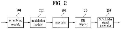
- FIG. 2 illustrates a signal processing operation for transmitting a UL signal at a UE.
- the transmitter 100a of the UE may include a scrambling module 201, a modulation mapper 202, a precoder 203, an RE mapper 204, and an SC-FDMA signal generator 205.
- the scrambling module 201 may scramble a transmission signal with a scrambling signal.
- the modulation mapper 202 modulates the scrambled signal to complex modulation symbols in Binary Phase Shift Keying (BPSK), Quadrature Phase Shift Keying (QPSK), or 16-ary/64-ary Quadrature Amplitude Modulation (16QAM/64QAM) according to the type of the transmission signal or a channel state.
- the precoder 203 precodes the complex modulation symbols and the RE mapper 204 maps the complex modulation symbols to time-frequency REs.
- the SC-FDMA signal generator 205 may transmit the processed signal to an eNB through an antenna port.
- FIG. 3 illustrates a signal processing operation for transmitting a DL signal at an eNB.
- the transmitter 100b of the transmitter may include scrambling modules 301, modulation mappers 302, a layer mapper 303, a precoder 304, RE mappers 305, and OFDMA signal generators 306.
- the scrambling modules 301 may scramble the signal or the codewords and the modulation mappers 302 may modulate the scrambled signal or codewords to complex modulation symbols, as is done in the UE illustrated in FIG. 2 .
- the layer mapper 303 may map the complex modulation symbols to a plurality of layers.
- the precoder 304 may multiply the layers by a precoding matrix and allocate the products to respective transmission antennas.
- the RE mappers 305 may map the antenna-specific transmission signals to time-frequency REs.
- the OFDMA signal generators 306 may transmit the processed signals through respective antenna ports.
- a Peak-to-Average Power Ratio becomes a problem with UL signal transmission from a UE.
- a UL signal is transmitted in SC-FDMA, while a DL signal is transmitted in OFDMA.
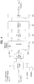
- FIG. 4 illustrates SC-FDMA and OFDMA to which the present invention is applied.
- the 3GPP system adopts OFDMA for DL and SC-FDMA for UL.
- a UE and an eNB are common in that each of the UE and the eNB has a serial-to-parallel converter 401, a subcarrier mapper 403, an M-point Inverse Discrete Fourier Transform (IDFT) module 404, and a Cyclic Prefix (CP) adder 406 in order to transmit a UL signal or a DL signal.
- the UE further includes an N-point Discrete Fourier Transform (DFT) module 402.
- DFT N-point Discrete Fourier Transform
- the N-point DFT module 402 counterbalances the effects of IDFT of the IDFT module 404 to some extent so that the transmission signal takes a single carrier property.
- FIG. 5 illustrates examples of mapping input symbols to subcarriers in a frequency domain in a manner that satisfies the single carrier property. If DFT symbols are allocated to subcarriers in the mapping scheme illustrated in FIG. 5(a) or 5(b) , a transmission signal satisfying the single carrier property may be achieved.
- FIG. 5(a) illustrates a localized mapping scheme and FIG. 5(b) illustrates a distributed mapping scheme.
- DFT-s-OFDM Clustered DFT-spread-OFDM
- a precoded signal is divided into a plurality of sub-blocks and mapped to non-contiguous subcarriers.
- FIGS. 6 , 7 and 8 illustrate examples of mapping input symbols to a single carrier in DFT-s-OFDM.
- FIG. 6 illustrates a signal processing operation for mapping DFT output samples to a single carrier in clustered SC-FDMA and FIGS. 7 and 8 illustrate signal processing operations for mapping DFT output samples to multiple carriers in clustered SC-FDMA.
- FIG. 6 illustrates an example of intra-carrier clustered SC-FDMA and FIGS. 7 and 8 illustrate examples of inter-carrier clustered SC-FDMA.
- CCs contiguous Component Carriers
- FIG. 8 with non-contiguous CCs allocated in the frequency domain, signals are generated from a plurality of IFFT blocks.
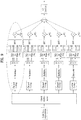
- FIG. 9 illustrates a signal processing operation in segmented SC-FDMA.
- segmented SC-FDMA As many IFFT modules as the number of DFT modules are used. Thus, as DFT modules are mapped to IFFT modules in a one-to-one correspondence, segmented SC-FDMA is a simple extension of the DFT spreading and IFFT frequency subcarrier mapping configuration of the existing SC-FDMA. Segmented SC-FDMA is also referred to as NxSC-FDMA or NxDFT-s-OFDMA. Herein, NxSC-FDMA and NxDFT-s-OFDMA are uniformly called segmented SC-FDMA. Referring to FIG. 9 , to relieve the single carrier property constraint, total time-domain modulation symbols are grouped into N groups (N is an integer larger than 1) and DFT-processed on a group basis in segmented SC-FDMA.
- N is an integer larger than 1
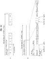
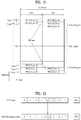
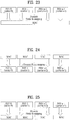
- FIG. 10 illustrates exemplary radio frame structures in a wireless communication system.
- FIG. 10(a) illustrates an exemplary radio frame of Frame Structure type 1 (FS-1) in the 3GPP LTE/LTE-A system
- FIG. 10(b) illustrates an exemplary radio frame of Frame Structure type 2 (FS-2) in the 3GPP LTE/LTE-A system.
- the frame structure illustrated in FIG. 10(a) may apply to a Frequency Division Duplex (FDD) mode and a Half FDD (H-FDD) mode
- the frame structure illustrated in FIG. 10(b) may apply to a Time Division Duplex (TDD) mode.
- FDD Frequency Division Duplex
- H-FDD Half FDD
- TDD Time Division Duplex
- a 3GPP LTE/LTE-A radio frame is 10ms (327200T s ) long and divided into 10 equal-sized subframes.
- the 10 subframes of a radio frame may be indexed.
- Each subframe is 1ms long, including two slots.
- the 20 slots of a radio frame may be indexed sequentially from 0 to 19. Each slot is 0.5ms long.
- a unit time over which one subframe is transmitted is defined as a Transmission Time Interval (TTI).
- Time resources may be identified by a radio frame number (or a radio frame index), a subframe number (or a subframe index), a slot number (or a slot index), etc.
- Radio frames may be configured for different duplexing modes. For example, DL transmission and UL transmission are distinguished by frequency in the FDD mode and thus a radio frame includes only DL subframes or UL subframes.
- a TDD radio frame is divided into UL subframes and DL subframes because DL transmission and UL transmission are distinguished by time in the TDD mode.
- FIG. 11 illustrates a UL subframe structure to which the present invention is applied.
- a UL subframe may be divided into a data region and a control region in the frequency domain.
- At least one PUCCH may be allocated to the control region to transmit UCI.
- At least one PUSCH may be allocated to the data region to transmit user data. If a UE operates in SC-FDMA in conformance to LTE release 8 or release 9, the UE may not transmit a PUCCH and a PUSCH simultaneously in order to maintain the single carrier property.
- the size and usage of UCI delivered on a PUCCH are different according to a PUCCH format.
- the size of UCI may also be changed according to a coding rate.
- the following PUCCH formats may be defined.
- [Table 1] lists modulation schemes and the numbers of bits per subframe for PUCCH formats
- [Table 2] lists the numbers of Reference Signals (RSs) per slot for PUCCH formats
- [Table 3] lists the positions of SC-FDMA symbols at which RSs are arranged, for PUCCH formats.
- PUCCH formats 2a and 2b are for a normal CP case.
- Subcarriers far from a Direct Current (DC) subcarrier are used for the control region of a UL subframe. That is, subcarriers at both ends of a UL transmission bandwidth are allocated for transmission of UCI.
- the DC subcarrier which is not used for signal transmission, is mapped to a carrier frequency f 0 during frequency upconversion in an OFDMA/SC-FDMA signal generator.
- a PUCCH for a UE is allocated to an RB pair in a subframe, the RBs of the RB pair occupying different subcarriers in the two slots of the subframe. It is said that the RB pair allocated to the PUCCH is frequency-hopped over a slot boundary. If frequency hopping is not used, the RB pair occupies the same subcarriers in the two slots. Since a PUCCH for a UE is allocated to an RB pair in a subframe irrespective of frequency hopping, the same PUCCH is transmitted twice in the subframe, each RB of the RB pair in one slot.
- PUCCH region An RB pair used for PUCCH transmission in a subframe is referred to as a PUCCH region.
- the PUCCH region and a code used in the PUCCH region are collectively referred to as PUCCH resources. That is, different PUCCH resources may be positioned in different PUCCH regions or may have different codes in the same PUCCH region.
- a PUCCH carrying ACK/NACK information is referred to as an ACK/NACK PUCCH
- a PUCCH carrying CQI/Precoding Matrix Index (PMI)/Rank Indicator (RI) information is referred to as a CQI/PMI/RI PUCCH
- SR PUCCH a PUCCH carrying SR information
- An eNB allocates PUCCH resources to a UE explicitly or implicitly so that the UE may transmit UCI in the PUCCH resources.
- UCI such as ACK/NACK information, CQI information, PMI information, RI information, and SR information may be transmitted in the control region of a UL subframe.
- a UE and an eNB transmit and receive signals or data to and from each other.
- the UE decodes the received data. If the data decoding is successful, the UE transmits an ACK to the eNB. On the contrary, if the data decoding is failed, the UE transmits a NACK to the eNB.
- the eNB transmits an ACK/NACK for the received data in the same manner as the UE.
- the UE receives a PDSCH from the eNB and transmits an ACK/NACK for the received PDSCH to the eNB on a PUCCH implicitly determined by a PDCCH carrying scheduling information about the PDSCH. If the UE fails to receive data on the PDSCH, this state may be considered to be a Discontinuous Transmission (DTX) state. In this case, the DTX state is handled as no data reception or the same state as a NACK (data reception but failed decoding) according to a predetermined rule.
- DTX Discontinuous Transmission
- FIG. 12 illustrates an operation for determining a PUCCH that will deliver an ACK/NACK, to which the present invention is applied.
- a plurality of PUCCH resources are shared among a plurality of UEs in a cell at each time point, rather than PUCCH resources for an ACK/NACK are allocated to each UE in advance.
- PUCCH resources in which a UE will transmit an ACK/NACK are determined implicitly by a PDCCH carrying scheduling information about DL data related to the ACK/NACK.
- a total region carrying PDCCHs in each DL subframe includes a plurality of CCEs and a PDCCH directed to the UE includes one or more CCEs.
- a CCE includes a plurality of Resource Element Groups (REGs) (e.g. 9 REGs).
- REGs Resource Element Groups
- One REG includes four successive REs except for REs carrying RSs.
- the UE transmits an ACK/NACK in PUCCH resources that are implicitly determined or calculated by a function of a specific CCE (e.g. a first CCE or a CCE with a lowest index) from among the CCEs of the received PDCCH.
- a specific CCE e.g. a first CCE or a CCE with a lowest index
- the lowest CCE index of a PDCCH is mapped to a PUCCH resource index for ACK/NACK transmission. If scheduling information about a PDSCH is delivered to a UE on a PDCCH including CCEs #4, #5, and #6 as illustrated in FIG. 12 , the UE transmits to the eNB an ACK/NACK in PUCCH resource #4 mapped to CCE #4 which is the first of the CCEs of the PDCCH.
- FIG. 12 illustrates an exemplary case in which there are up to M PUCCH resources in a UL subframe, for a DL subframe having up to M' CCEs. While M' may be equal to M, M' and M may be different and thus the CCEs may be mapped to the PUCCH resources in an overlapped manner.
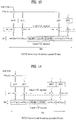
- FIGS. 13 and 14 illustrate slot-level structures of PUCCH format 1a and PUCCH format 1b, for ACK/NACK transmission.
- FIG. 13 illustrates PUCCH formats 1a and 1b in a normal CP case
- FIG. 14 illustrates PUCCH formats 1a and 1b in an extended CP case.
- PUCCH formats 1a and 1b the same UCI is repeated on a slot basis in a subframe.
- a UE transmits an ACK/NACK signal in different resources defined by a different Cyclic Shift (CS) (frequency-domain code) of a Computer-Generated Constant Amplitude Zero Auto Correlation (CG-CAZAC) sequence and a different Orthogonal Cover (OC) or Orthogonal Cover Code (OCC) (time-domain spreading code).
- CS Cyclic Shift
- CG-CAZAC Computer-Generated Constant Amplitude Zero Auto Correlation
- OC Orthogonal Cover
- OCC Orthogonal Cover Code
- a total of 18 UEs may be multiplexed into the same Physical Resource Block (PRB) in a single antenna case.
- PRB Physical Resource Block
- An orthogonal sequence w0, w1, w2, w3 may apply to the time domain (after FFT modulation) or to the frequency domain (before FFT modulation).
- the slot-level structure of PUCCH format 1 for SR transmission is identical to that of PUCCH formats 1a and 1b, except for a modulation scheme.
- PUCCH resources defined by a CS, an OC, a PRB, and an RS may be allocated to a UE by RRC signaling, for transmission of SR information and an ACK/NACK for Semi-Persistent Scheduling (SPS).
- SPS Semi-Persistent Scheduling
- PUCCH resources may be allocated to a UE implicitly using the lowest CCE index of a PDCCH corresponding to a PDSCH or the lowest CCE index of an SPS-releasing PDCCH, for a dynamic ACK/NACK feedback (or an ACK/NACK feedback for non-persistent scheduling) and an ACK/NACK feedback for the SPS-releasing PDCCH.
- FIG. 15 illustrates PUCCH format 2/2a/2b in a normal CP case
- FIG. 16 illustrates PUCCH format 2/2a/2b in an extended CP case.
- one subframe includes 10 QPSK data symbols except for RS symbols in the normal CP case.
- Each QPSK symbol is spread by a CS in the frequency domain and then mapped to a corresponding SC-FDMA symbol.
- SC-FDMA symbol-level CS hopping may be used to randomize inter-cell interference.
- RSs may be multiplexed in Code Division Multiplexing (CDM) using CSs.
- CDM Code Division Multiplexing
- 12 or 6 UEs may be multiplexed into the same PRB. That is, a plurality of UEs may be multiplexed using CS+OC+PRB and CS+PRB respectively in PUCCH format 1/1a/1b and PUCCH format 2/2a/2b.
- Length-4 orthogonal sequences (i.e. OCs) and length-3 orthogonal sequences (i.e. OCs) available to PUCCH format 1/1a/1b are illustrated in [Table 4] and [Table 5], respectively.
- Orthogonal sequences for RSs in PUCCH format 1/1a/1b are given as illustrated in [Table 6] [Table 6] Sequence index Normal CP Extended CP 0 [111] [11] 1 [1 e j2 ⁇ / 3 e 4 ⁇ / 3 ] [1-1] 2 [1 e j4 ⁇ / 3 e 2 ⁇ / 3 ] N/A
- FIG. 17 illustrates ACK/NACK channelization for PUCCH formats 1a and 1b.
- ⁇ shift PUCCH 2.
- FIG. 18 illustrates channelization for PUCCH format 1/1a/1b and PUCCH format 2/2a/2b that are combined in the same PRB.
- CS hopping and OC remapping may be performed in the following manner:
- Resources n r for PUCCH format 1/1a/1b include the following set:
- n cs n oc , and n rb .
- n rb (n cs , n oc , and n rb ).
- a set of a CQI, a PMI, and an RI and a set of a CQI and an ACK/NACK may be transmitted in PUCCH format 2/2a/2b.
- RM Reed Muller
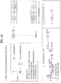
- a UL CQI may be channel-encoded in the LTE system, as follows. First, a bit stream a 0 , a 1 , a 2 , a 3 , ..., a A-1 is channel-encoded with a (20, A) RM code. [Table 7] lists base sequences for the (20, A) code. a 0 and a A-1 are the Most Significant Bit (MSB) and Least Significant Bit (LSB) of the bit stream, respectively. In the extended CP case, the maximum number of transmission bits is 11, aside from the case of simultaneous CQI and ACK/NACK transmission. The bit stream may be encoded to 20 bits using the RM code and then modulated in QPSK.
- MSB Most Significant Bit
- LSB Least Significant Bit
- the channel-coded bits b 0 , b 1 , b 2 , b 3 , ..., b B-1 may be generated by the following equation.
- [Table 8] illustrates a UCI field for a wideband CQI feedback (a CQI feedback for a PDSCH transmitted through a single antenna port, by transmit diversity, or by open-loop spatial multiplexing).
- [Table 9] illustrates UCI fields for a wideband CQI and PMI feedback. These fields report about PDSCH transmission in closed-loop spatial multiplexing.
- [Table 10] illustrates a UCI field for an RI feedback in wideband reporting.
- [Table 10] Field Bit widths Field 2 antenna ports 4 antenna pots 2 antenna ports Maxim 2 layers Maximum 4 layers RI 1 1 2
- FIG. 19 illustrates PRB allocation. As illustrated in FIG. 19 , PRBs may be used for PUCCH transmission in slot n s .
- a multi-carrier system or Carrier Aggregation (CA) system aggregates a plurality of carriers having narrower bandwidths than a target bandwidth, for wideband support.
- the bandwidths of the plurality of carriers may be restricted to bandwidths used in the legacy system.
- the legacy LTE system supports 1.4, 3, 5, 10, 15, and 20MHz and the LTE-A system evolved from the LTE system may support a broader bandwidth than 20MHz by aggregating LTE bandwidths.
- a new bandwidth may be defined irrespective of the legacy bandwidths to thereby support CA.
- the term multi-carrier is interchangeable with CA and bandwidth aggregation.
- CA may cover both aggregation of contiguous carriers and aggregation of non-contiguous carriers.
- CA may cover both intra-band CA and inter-band CA.
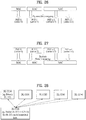
- FIG. 20 illustrates a concept of managing DownLink Component Carriers (DL CCs) at an eNB and FIG. 21 illustrates a concept of managing UpLink Component Carriers (UL CCs) at a UE.
- DL CCs DownLink Component Carriers
- UL CCs UpLink Component Carriers
- a MAC layer is taken simply as a higher layer in FIGS. 19 and 20 .
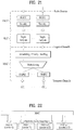
- FIG. 22 illustrates a concept of managing multiple carriers using one MAC entity at an eNB
- FIG. 23 illustrates a concept of managing multiple carriers using one MAC entity at a UE.
- a single MAC entity manages and operates one or more frequency carriers, for transmission and reception. Because the frequency carriers managed by the single MAC entity do not need to be contiguous, resource management is more flexible.
- one Physical (PHY) entity means one CC, for the convenience of description.
- One PHY entity does not necessarily refer to an independent Radio Frequency (RF) device. Although one independent RF device generally means one PHY entity, this is not always true. Thus one RF device may include a plurality of PHY entities.
- FIG. 24 illustrates a concept of managing multiple carriers using a plurality of MAC entities at an eNB
- FIG. 25 illustrates a concept of managing multiple carriers using a plurality of MAC entities at a UE
- FIG. 26 illustrates another concept of managing multiple carriers using a plurality of MAC entities at an eNB
- FIG. 27 illustrates another concept of managing multiple carriers using a plurality of MAC entities at a UE.
- a plurality of MAC entities may control a plurality of carriers as illustrated in FIGS. 24 to 27 .
- the MAC entities may control the carriers at a one-to-one correspondence as illustrated in FIGS. 24 and 25 , whereas a plurality of MAC entities may control some of the plurality of carriers in a one-to-one correspondence and one MAC entity may control the remaining one or more carriers as illustrated in FIGS. 26 and 27 .
- the above system has N carriers which may be used contiguously or non-contiguously. This applies to UL and DL.
- a TDD system is designed so as to use N carriers each for DL and UL transmission, while an FDD system is designed so as to use a plurality of carriers separately for DL and UL transmissions.
- the FDD system may support asymmetrical CA in which the number of aggregated carriers and/or a carrier bandwidth is different for DL and UL.
- all CCs may be configured to ensure backward compatibility with a legacy system. However, CCs that do not ensure backward compatibility are not excluded from the present invention.
- FIG. 28 illustrates asymmetrical CA with five DL CCs linked to one UL CC.
- the asymmetrical CA may be configured from the viewpoint of UCI transmission.
- UCI related to a plurality of DL CCs e.g. ACKs/NACKs related to the DL CCs
- UCI related to a plurality of DL CCs is transmitted in one UL CC.
- specific UCI e.g. an ACK/NACK related to a DL CC
- a predetermined one UL CC e.g. a Primary CC (PCC) or Primary Cell (PCell)
- each DL CC may deliver up to two codewords and the number of ACKs/NACKs for each CC depends on the maximum number of codewords set for the CC (e.g. if an eNB sets 2 as the maximum number of codewords for a specific CC, even though a specific PDCCH uses only one codeword in the CC, a related ACK/NACK has as many codewords as the maximum number of codewords set for the CC, that is, two codewords), a UL ACK/NACK needs at least two bits per DL CC. In this case, at least 10 ACK/NACK bits are required to transmit ACKs/NACKs for data received in five DL CCs, in one UL CC.
- UCI payload may be increased.
- ACK/NACK information for a codeword is taken as an example in the present invention, it is to be clearly understood that a transport block corresponding to the codeword exists and the ACK/NACK information may apply as an ACK/NACK for the transport block.
- a UL anchor CC (i.e. a UL PCC) is a CC in which a PUCCH or UCI is transmitted.
- the UL anchor CC may be determined cell-specifically or UE-specifically.
- a UE may determine a CC in which the UE attempts initial random access as a PCC.
- a DTX state may be fed back explicitly or may be fed back as the same state as a NACK.
- a cell is defined as a combination of DL and UL resources, while the UL resources are optional. Accordingly, a cell may include DL resources only or both DL and UL resources. If CA is supported, the linkage between the carrier frequencies (or DL CCs) of DL resources and the carrier frequencies (or UL CCs) of UL resources may be indicated by system information.
- a cell operating in a primary frequency resource (or a PCC) may be referred to as a PCell and a cell operating in a secondary frequency resource (an SCC) may be referred to as an SCell.
- the PCell is used for a UE to establish an initial connection or to re-establish a connection.
- the PCell may be a cell indicated during handover. Only one PCell may exist in CA in LTE-A release 10.
- the SCell may be configured after an RRC connection is established and used to provide additional radio resources. Both a PCell and an SCell may be collectively referred to as serving cells. Accordingly, if CA has not been configured for a UE in RRC_CONNECTED state or the UE in RRC_CONNECTED state does not support CA, one serving cell including only a PCell exists for the UE. On the other hand, if CA has been configured for a UE in RRC_CONNECTED state, one or more serving cells including a PCell and one or more SCells exist for the UE.
- a network may add one or more SCells to a PCell initially configured during connection establishment, for a UE after initial security activation is initiated. Therefore, the terms PCC, PCell, primary (radio) resource, and primary frequency resource are interchangeably used. Likewise, the terms SCC, SCell, secondary (radio) resource, and secondary frequency resource are interchangeably used.
- a new PUCCH format proposed by the present invention will be referred to as a CA PUCCH format or PUCCH format 3, considering that PUCCH format 1 to PUCCH format 2 are defined in the legacy LTE release 8/9.
- the technical spirit of the proposed PUCCH format manner or in a similar manner.
- embodiments of the present invention are applicable to a periodic PUSCH structure that delivers control information periodically or an aperiodic PUSCH structure that delivers control information aperiodically.
- PUCCH format 3 which uses a legacy LTE UCI/RS symbol structure of PUCCH format 1/1a/1b (a normal CP case).
- the subframe-level/slot-level UCI/RS symbol structure of PUCCH format 3 is purely exemplary and thus the present invention is not limited to the specific structure.
- the number and positions of UCI/RS symbols in PUCCH format 3 of the present invention may be changed freely according to a system design.
- PUCCH format 3 may be defined based on a legacy LTE RS symbol structure of PUCCH format 2/2a/2b according to an embodiment of the present invention.
- PUCCH format 3 may be used to transmit UCI of any type/size.
- information such as an HARQ ACK/NACK, a CQI, a PMI, an RI, an SR, etc. may be transmitted in PUCCH format 3 and the information may have payload of any size in the embodiment of the present invention.
- ACK/NACK transmission in PUCCH format 3 of the present invention will be described below.
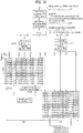
- FIGS. 29 to 32 illustrate exemplary structures of PUCCH format 3 and signal processing operations based on the PUCCH format 3 structures according to the present invention. Particularly, FIGS. 29 to 32 illustrate exemplary DFT-based PUCCH format structures.
- a DFT-based PUCCH structure a PUCCH is DFT-precoded, spread with a time-domain OC at an SC-FDMA level, and then transmitted.
- DFT-based PUCCH formats are collectively referred to as PUCCH format 3.
- FIG. 29 illustrates a structure of PUCCH format 3 using an OC with a Spreading Factor (SF) of 4.
- a channel coding block channel-encodes transmission bits a_0, a_1, ..., a_M-1 (e.g. multiple ACK/NACK bits) to coded bits (encoded bits or coding bits) (or a codeword) b_0, b_1, ..., b_N-1.
- M is the length of the transmission bits
- N is the length of the coded bits.
- the transmission bits include UCI, for example, multiple ACKs/NACKs for data received on a plurality of PDSCHs in a plurality of DL CCs.
- the transmission bits a_0, a_1, ..., a_M-1 are jointly encoded irrespective of the type/number/size of UCI. For example, if the transmission bits include ACKs/NACKs for a plurality of DL CCs, the transmission bits are wholly encoded, rather than they are encoded on a DL CC basis and on an ACK/NACK bit basis. As a result, a single codeword is produced.
- the channel coding includes, not limited to, simple repetition, simplex coding, RM coding, punctured RM coding, Tail-Biting Convolutional Coding (TBCC), Low-Density Parity-Check (LDPC) coding, or Turbo coding.
- the coded bits may be rate-matched in consideration of a modulation order and the amount of resources.
- the rate matching function may be incorporated into the channel coding block or may be performed in a separate functional block.
- the channel coding block may generate a single codeword by encoding a plurality of pieces of control information using a (32, 0) RM code and may perform cyclic buffer rate-matching on the codeword.
- a modulator generates modulation symbols c_0, c_1, ..., c_L-1 by modulating the coded bits b_0, b_1, ..., b_N-1.
- L is the size of modulation symbols.
- the coded bits b_0, b_1, ..., b_N-1 are modulated by changing the size and phase of the transmission signal.
- n-Phase Shift Keying (n-PSK) or n-QAM may be used as a modulation scheme (n is an integer equal to or larger than 2).
- the modulation scheme may be BPSK, QPSK, 8-PSK, QAM, 16-QAM, 64-QAM, etc.
- a divider divides the modulation symbols c_0, c_1, ..., c_L-1 to each slot.
- the sequence/pattern/method of dividing the modulation symbols to each slot is not limited to a specific sequence/pattern/method.
- the divider may divide the modulation symbols to each slot sequentially, starting from the first modulation symbol (localized scheme). In this case, the modulation symbols c_0, c_1, ..., c_L/2-1 may be divided to slot 0 and the modulation symbols c_L/2, c_L/2+1, ..., c_L-1 may be divided to slot 1.
- the modulation symbols may be interleaved (or permuted). For example, even-numbered modulation symbols may be divided to slot 0, while odd-numbered modulation symbols may be divided to slot 1. The order of the modulation and the division operations may be changed.
- DFT precoders perform DFT precoding (e.g. 12-point DFT) on the modulation symbols divided to the respective slots in order to generate a single carrier waveform.
- DFT precoding e.g. 12-point DFT
- the modulation symbols c_0, c_1, ..., c_L/2-1 divided to slot 0 are DFT-precoded to DFT symbols d_0, d_1, ..., d_L/2-1
- the modulation symbols c_L/2, c_L/2+1, ..., c_L-1 divided to slot 1 are DFT-precoded to DFT symbols d_L/2, d_L/2+1, ..., d_L-1.
- the DFT precoding may be replaced with another equivalent linear operation (e.g. Walsh precoding).
- the SC-FDMA symbol-level time-domain spreading is performed using a spreading code (sequence).
- the spreading code includes a quasi-OC and an OC.
- the quasi-OC includes, not limited to, a Pseudo-Noise (PN) code.
- the OC includes, not limited to, a Walsh code and a DFT code. While an OC is taken as an exemplary spreading code for the convenience of description, the OC may be replaced with a quasi-OC.
- the maximum size of a spreading code (or a maximum SF) is limited by the number of SC-FDMA symbols in which control information is transmitted.
- the SF means the spreading degree of control information.
- the SF may be related to a multiplexing order or antenna multiplexing order of a UE.
- the SF may be changed to, for example, 1, 2, 3, 4, ... depending on system requirements.
- An SF may be predefined between an eNB and a UE or indicated to the UE by DCI or RRC signaling.
- a signal generated in the above operation is mapped to subcarriers of a PRB and converted to a time-domain signal by IFFT.
- a CP is added to the time-domain signal and the resulting SC-FDMA symbols are transmitted through an RF end.
- each step will be described in greater detail on the assumption that ACKs/NACKs for five DL CCs are transmitted.
- an ACK/NACK for the DL CC may be 12 bits, with a DTX state included.
- a (rate-matched) coding block may be 48 bits.
- the coded bits are modulated to 24 QPSK modulation symbols which are divided to two slots, 12 QPSK symbols to each slot.
- the QPSK symbols of each slot are converted to 12 DFT symbols by 12-point DFT.
- FIG. 30 illustrates an exemplary structure of PUCCH format 3 using an OC with an SF of 5.
- the signal processing operation of FIG. 30 is basically identical to the signal processing operation described above with reference to FIG. 29 , except for different numbers and positions of UCI SC-FDMA symbols and RS SC-FDMA symbols.
- Spreading blocks may reside at the front ends of DFT precoders.
- an LTE RS structure may still be used.
- a base sequence may be cyclically shifted.
- the multiplexing capacity of a data part is 5.
- the multiplexing capacity of an RS part is determined by a CS interval ⁇ shift PUCCH .
- FIG. 31 illustrates an exemplary structure of PUCCH format 3, which may increase a slot-level multiplexing capacity.
- the total multiplexing capacity may be increased by applying the SC-FDMA symbol-level spreading described before with reference to FIGS. 29 and 30 to RSs.
- the use of a Walsh cover (or a DFT code cover) in a slot doubles the multiplexing capacity. Therefore, the multiplexing capacity is 8 for ⁇ shift PUCCH , thereby not decreasing the multiplexing capacity of the data part.
- linear modifications of [y1 y2] e.g. [j j], [j -j], [1 j], [1 -j], etc.
- FIG. 32 illustrates an exemplary structure of PUCCH format 3, which may increase a subframe-level multiplexing capacity.
- An operation for processing PUCCH format 3 is not restricted to operation orders illustrated in FIGS. 29 to 32 .
- Cross carrier scheduling is to schedule a data channel transmitted in a PCC or another CC by a control channel transmitted in the PCC using a CIF.
- FIG. 33 illustrates an exemplary application of cross carrier scheduling. Particularly, FIG. 33 illustrates a cross carrier scheduling scheme using a CIF, in the case where three cells (or CCs) are allocated to a Relay Node (RN). It is assumed herein that DL Cell (DL CC) #A is a PCell and the other CCs #B and #C are SCells.
- DL Cell (DL CC) #A is a PCell and the other CCs #B and #C are SCells.
- the present invention proposes a method for efficiently conducting UL communication of a UE in a CA situation where the UE transmits and receives data in two or more frequency spectrums, frequency bands, or carriers.
- the UE is configured to communicate in two CCs.
- PCC PCell
- SCC SCell
- the UE receives various control signals such as a PDCCH in the PCell and data transmission and reception in the SCell is cross-carrier scheduled by a control signal in the PCell.
- CC #1 is a DL PCell (LTE-A frequency band)
- CC #3 is a UL PCell (LTE-A frequency band)
- CC #2 is an SCell (unlicensed band).
- FIG. 34 is a simplified diagram illustrating the FDD system.
- DL/UL scheduling information is transmitted in CC #1 as the DL PCell.
- a UL ACK/NACK and CSI are transmitted in CC #3 as the UL PCell.
- CC #2 e.g. an SCell and an unlicensed band
- a DL PCell and a UL PCell operate in the same band.
- an eNB schedules a UL SubFrame (SF) of CC #2 (e.g. an SCell) for a UE by cross carrier scheduling in CC #1 (e.g. a DL PCell)
- CC #2 e.g. an SCell
- the eNB and the UE are not allowed to use CC #2 exclusively. Rather, the eNB and the UE should use CC #2 by contention with other systems based on Carrier Sensing (CS). Therefore, the eNB may not make clear "the starting/ending time of PUSCH transmission in CC #2" or "whether PUSCH transmission is available or not" for the UE.
- CS Carrier Sensing
- CC #2 e.g. an SCell
- a DL PCell and a UL PCell operate in the same frequency band.
- the present invention proposes a method for transmitting information indicating "whether PUSCH transmission is available in an SCell" and information about "the starting/ending time of PUSCH transmission" using UL resources of a PCell for which a transmission opportunity is ensured for a UE all the time or at a preset time point.
- the information transmitted in the UL resources of the PCell is not limited to the information indicating "whether PUSCH transmission is available in an SCell" and the information about "the starting/ending time of PUSCH transmission” and may further include various pieces of information related to SCell-based PUSCH transmission.
- a UL subframe of CC #2 (e.g. an SCell) is scheduled by cross carrier scheduling in CC #1 (e.g. a DL PCell).
- the present invention is not limited to the assumption. It is obvious that the present invention is also applicable to aggregation of two or more CCs or non-cross carrier scheduling.
- the first slot' or 'the second slot' of SF #(n+k) in which the UE performs a CS operation may be used for transmission of "Carrier Reservation Transport Block (CRTB)".
- CRTB Carrier Reservation Transport Block
- a maximum time period during which the UE performs the CS operation to determine the state of CC #2 may be set to T max . If the UE determines that CC #2 is busy during the time period T max , the UE may "repeat the CS operation on CC #2 in the next slot, discontinuing the CS operation on CC #2 in the corresponding slot" or may "give up PUSCH transmission in the corresponding SF".
- the eNB may indicate a value of T max and a CS rule to the UE by a higher-layer signal or a physical-layer signal.
- a CRTB is a kind of "dummy information" or "a copy of a part of a later transmitted PUSCH", which the UE transmits to reserve CC #2 as its resources until before actual PUSCH transmission, if the UE determines by a CS operation that CC #2 is idle during a predetermined time period (e.g. a time period T).
- the eNB may determine according to a predefined rule what information a CRTB transmitted by a UE includes and/or whether the CRTB is transmitted from a UE communicating with the eNB.
- the UE may transmit information to the eNB efficiently by including a UE Identifier (ID) of the UE or an indicator indicating whether a (current) transmitted signal serves as a CRTB.
- ID UE Identifier
- the UE determines by a CS operation that CC #2 is idle for a predetermined time period (e.g. the time period T)
- the UE transmits a CRTB.
- the starting time of CRTB transmission is ["the start of a specific slot of SF #(n+k) in which the UE starts the CS operation" + T].
- the ending time of the CRTB transmission may be the slot boundary (or SF boundary) of a PCC (e.g. CC #1) closest to the starting time of the CRTB transmission.
- the length of a CRTB e.g. L spans from the starting time of the CRTB transmission to the ending time of the CRTB transmission.
- an eNB may transmit to the UE an additional "activation message" that activates the UL grant.
- the eNB may also transmit the activation message to the UE in a next SF (e.g. SF #(n+v) where v is an integer equal to or larger than 5) as well as in SF #(n+4).
- a next SF e.g. SF #(n+v) where v is an integer equal to or larger than 5
- the activation message may include information indicating the transmission time of a UL grant linked to the activation message (e.g. a predefined indicator serving the usage). For example, if a preamble is used as the activation message, the information may be mapped to or included in a corresponding preamble sequence.
- the activation message is a "preamble sequence known" to both the eNB and the UE.
- the known preamble sequence may serve many other usages as well as the usage of an activation message that activates a UL grant received at a specific time point.
- the usage of the preamble sequence may be set to indication of a purpose that radio resources at a specific time point will serve, indication of a transmission time of a PUSCH (e.g. the position of a subframe or an OFDM symbol), or indication of a UL HARQ process ID linked to PUSCH transmission activated by the preamble sequence.
- the UE Upon receipt of the activation message, the UE performs a CS operation to determine whether CCE #2 is "idle” or “busy", in a "slot in which the activation message has been received” or a "(predetermined) next specific slot". If the CCE #2 is idle for a predetermined time period (e.g. the time period T), the UE transmits a PUSCH.
- a predetermined time period e.g. the time period T
- a UE When a UL subframe of CC #2 (e.g. an SCell) is scheduled by cross carrier scheduling in CCE #1 (e.g. a PCell), a UE transmits to an eNB information indicating "whether a PUSCH is transmitted in CC #2" and information about "the starting/ending time of PUSCH transmission” in the following manner.
- CC #2 e.g. an SCell
- CCE #1 e.g. a PCell
- PUSCH transmission may take place "in units of a multiple of (1/Y)x(Length of Slot) of CC #1 (e.g. a DL PCell)" (Y ⁇ 1 and Y is an integer).
- the eNB may transmit information about a value of Y to the UE by a higher-layer signal or a physical-layer signal.
- L_information information about the starting time of PUSCH transmission in CC #2.
- the starting time of PUSCH transmission will first be described in detail.
- the UE may notify the eNB of information about the starting time of PUSCH transmission (e.g. L_information) in UL resources (e.g. a PUCCH or a PUSCH) of CC #3 (e.g. a UL PCell) linked (or allocated) for mapping the information.
- L_information information about the starting time of PUSCH transmission
- UL resources e.g. a PUCCH or a PUSCH
- CC #3 e.g. a UL PCell linked (or allocated) for mapping the information.
- the UE may transmit L_information to the eNB in PUCCH resources of CC #3 (e.g. the UL PCC) positioned at an (actual) starting time or point of PUSCH transmission" or "(predetermined) fixed specific PUCCH resources of CC #3 (e.g. the UL PCC) irrespective of the (actual) starting time or point of PUSCH transmission".
- PUCCH resources of CC #3 e.g. the UL PCC
- the PUCCH resources of CC #3 (e.g. the UL PCC) used for transmission of L_information may be "resources linked to a CCE of a PDCCH granting the PUSCH resources of CC #2 (e.g. resources linked to a lowest CCE index of the UL grant)".
- PUCCH resource waste may be reduced.
- L_information may be "1 bit”. That is, if L_information (e.g. 1 bit) is '0', this may imply that no PUSCH transmission takes place in CC #2 of a corresponding slot (or a corresponding subframe). If L_information is '1', this may imply that PUSCH transmission takes place in CC #2, starting from the start of the corresponding slot (or the start of a next slot).
- the L_information may be "2 bits". That is, if L_information (e.g. 2 bits) is '00', this may imply that no PUSCH transmission takes place in CC #2 of a corresponding slot. If L_information is '01', this may imply that PUSCH transmission starts in CC #2 at a point 1/4 x (Length of SF) apart from the start of an SF of the DL PCC (e.g. CC #1). If L_information is '10', this may imply that PUSCH transmission starts in CC #2 at a point 1/2 x (Length of SF) (e.g. the start of the second slot) apart from the start of the SF of the DL PCC (e.g.
- CC #1 If L_information is '11', this may imply that PUSCH transmission starts in CC #2 at a point 3/4 x (Length of SF) apart from the start of the SF of the DL PCC (e.g. CC #1).
- a part of L_information, Bit first allocated to a first PUCCH resource of CC #3 (e.g. the UL PCC) and a part of L_information, Bit second allocated to a second PUCCH resource of CC #3 (e.g. the UL PCC) may be defined differently.
- the first and second PUCCH resources may be respectively the first and second slot areas of PUCCH resources linked to one CCE index.
- this method is effective. For example, if the UE reports the starting time of PUSCH transmission to the eNB in CC #3 in the same subframe as a PUSCH of CC #2, the UE may just report to the eNB at a time corresponding to the first slot whether a PUSCH is transmitted in the first slot of CC #2. Thus, it is not impossible for the UE to report to the eNB whether a PUSCH is transmitted in the second slot, in other words, whether a PUSCH is finally transmitted in a corresponding subframe and the starting time of the PUSCH transmission. Therefore, the afore-described method may enable transmission of more accurate information by reducing the amount of information reported in the first slot.
- the UE may use a specific PUCCH format configured for this usage (e.g. PUCCH format 3 (in the LTE system)) in a restrictive manner.
- resources at a specific position, preset for this usage between the eNB and the UE may be used as UL resources of CC #3 (e.g. the UL PCC) to which L_information is mapped.
- a field serving this usage may be newly created in an existing PUCCH format, for transmission of L_information.
- the UE may transmit information indicating "whether a PUSCH is transmitted in CC #2" to the eNB in similar methods to the above-described methods for transmitting L_information.
- the ending time of PUSCH transmission in CC #2 from a UE may be set to "a time point apart from the starting time of PUSCH transmission by a preset PUSCH length L _PUSCH (e.g. a fixed length of PUSCH)" or "an SF boundary or slot boundary of CC #1 (e.g. the DL PCell) closest to the starting time of PUSCH transmission”.
- L _PUSCH e.g. a fixed length of PUSCH
- an SF boundary or slot boundary of CC #1 e.g. the DL PCell
- Case 3 a method for setting the ending time of PUSCH transmission to an SF boundary of CC #1 (e.g. the DL PCell) closest to the starting time of PUSCH transmission will be called Case 3.
- Case 4 A method for setting the ending time of PUSCH transmission to a slot boundary of CC #1 (e.g. the DL PCell) closest to the starting time of PUSCH transmission will be called Case 4.
- the UE may additionally transmit information about the ending time of PUSCH transmission in CC #2 to the eNB in methods similar to the afore-described methods for transmitting L_information (e.g. a method for transmitting L_information in UL resources (e.g. a PUCCH or PUSCH) of the UL PCC).
- L_information e.g. a method for transmitting L_information in UL resources (e.g. a PUCCH or PUSCH) of the UL PCC).
- the present invention is not limited thereto.
- a time point before or after the transmission timing of a PUSCH in an SCell, or a preset specific time point may be used in the present invention.
- a UE When a UL subframe of CC #2 (e.g. an SCell) is scheduled by cross carrier scheduling in CC #1 (e.g. a DL PCell), a UE performs a CS operation to determine the state of CC #2.
- CC #2 e.g. an SCell
- a UE When a UL subframe of CC #2 (e.g. an SCell) is scheduled by cross carrier scheduling in CC #1 (e.g. a DL PCell), a UE performs a CS operation to determine the state of CC #2.
- the UE may transmit at least one bit indicating this state (ST_information) in UL resources (e.g. a PUCCH or PUSCH) of, for example, CC #3 (e.g. a UL PCC) to the eNB.
- UL resources e.g. a PUCCH or PUSCH
- CC #3 e.g. a UL PCC
- the UE may transmit ST information in methods similar to the method for transmitting L_information (e.g. a method for transmitting L information in UL resources (a PUCCH or PUSCH) of the UL PCC).
- Embodiments of the present invention illustrated in FIGS. 35 to 40 provide "various method for scheduling a UL subframe of CC #2 (e.g. an SCell) by cross carrier scheduling in CC #1 (e.g. a DL PCell)" as well as “the proposed operation methods”. The principles of these methods are embraced as the proposed methods of the present invention.
- the present invention is not limited thereto.
- a time point before or after the transmission timing of the PUSCH in the SCell, or a preset specific time point may be used in the present invention.
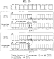
- the UE determines as a result of the CS operation of CC #2, starting from the first slot of SF #(n+4) that CC #2 is idle for a time period T.
- the UE transmits a CRTB for a time period from [the start of the first slot of SF #(n+4) + T] to [the end of the first slot of SF #(n+4)] and transmits a PUSCH for a time period from [the start of the second slot of SF #(n+4)] to [the end of the second slot of SF #(n+4)].
- the UE transmits to the eNB 1-bit information about the starting time of the PUSCH transmission (e.g. L_information) (e.g. '1' indicating the start of the (actual) PUSCH transmission at [the start of the second slot of SF #(n+4)) in PUCCH resources (the second slot) of CC #3 (e.g. a UL PCC) at the starting time of the actual PUSCH transmission (e.g. in the second slot of SF #(n+4)).
- L_information e.g. '1' indicating the start of the (actual) PUSCH transmission at [the start of the second slot of SF #(n+4)
- PUCCH resources the second slot of CC #3 (e.g. a UL PCC)
- the starting time of the actual PUSCH transmission e.g. in the second slot of SF #(n+4)
- the ending time of the PUSCH transmission may be [the end of the second slot of SF #(n+4)].
- the UE determines as a result of the CS operation of CC #2 starting from the first slot of SF #(n+4) that CC #2 is busy for a preset time period T max and thus does not transmit a PUSCH in the second slot of SF #(n+4).
- the UE may transmit to the eNB 1-bit information about this situation (e.g. '0' indicating no PUSCH transmission in SF #(n+4)) in PUCCH resources of the second slot of SF #(n+4) in CC #3 (e.g. the UL PCC).
- the present invention is not limited thereto.
- a time point before or after the transmission timing of the PUSCH in the SCell, or a preset specific time point may be used in the present invention.
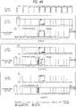
- FIG. 36 illustrates a specific exemplary operation according to the first embodiment of the present invention.
- This case may be regarded as a kind of the afore-described Case 1.
- the UE determines as a result of the CS operation of CC #2, starting from the second slot of SF #(n+3) that CC #2 is idle for a time period T.
- the UE transmits a CRTB for a time period from [the start of the second slot of SF #(n+3) + T] to [the end of the second slot of SF #(n+3)] and transmits a PUSCH for a time period from [the start of the first slot of SF #(n+4)] to [the end of the second slot of SF #(n+4)].
- the UE transmits to the eNB 1-bit information about the starting time of the PUSCH transmission (e.g. L_information) (e.g. '1' indicating the start of the (actual) PUSCH transmission at [the start of the first slot of SF #(n+4)]) in PUCCH resources (the first slot) of CC #3 (e.g. a UL PCC) at the starting time of the actual PUSCH transmission (e.g. in the first slot of SF #(n+4)).
- L_information e.g. '1' indicating the start of the (actual) PUSCH transmission at [the start of the first slot of SF #(n+4)]
- the ending time of the PUSCH transmission is [the end of the second slot of SF #(n+4)] according to the preset method of Case 3.
- the UE determines as a result of the CS operation of CC #2 starting from the second slot of SF #(n+3) that CC #2 is busy for a preset time period T max and thus discontinues the CS operation in the corresponding slot. Then the UE resumes the CS operation, starting from the first slot of SF #(n+4).
- the UE determines as a result of the CS operation of CC #2, starting from the first slot of SF #(n+4) that CC #2 is idle for a time period T. Then the UE transmits a CRTB for a time period from [the start of the first slot of SF #(n+4) + T] to [the end of the first slot of SF #(n+4)] and transmits a PUSCH for a time period from [the start of the second slot of SF #(n+4)] to [the end of the second slot of SF #(n+4)].
- the UE transmits to the eNB 1-bit information set to '0' indicating no PUSCH transmission in the first slot of SF #(n+4) in PUCCH resources of the first slot of SF #(n+4) in CC #3 (e.g. the UL PCC) and 1-bit information set to '1' indicating the start of the PUSCH transmission in [the start of the second slot of SF #(n+4)] in PUCCH resources of the second slot of SF #(n+4) in CC #3 (e.g. the UL PCC).
- the ending time of the PUSCH transmission is [the end of the second slot of SF #(n+4)] according to the preset method of Case 3.
- the UE determines as a result of the CS operation of CC #2 starting from the second slot of SF #(n+3) that CC #2 is busy for the preset time period T max and thus does not transmit a PUSCH in SF #(n+4).
- the UE may transmit to the eNB 1-bit information about this situation (e.g. '0' indicating no PUSCH transmission in SF #(n+4)) in PUCCH resources of the first slot of SF #(n+4) in CC #3 (e.g. the UL PCC).
- eNB 1-bit information about this situation (e.g. '0' indicating no PUSCH transmission in SF #(n+4)) in PUCCH resources of the first slot of SF #(n+4) in CC #3 (e.g. the UL PCC).
- the present invention is not limited thereto.
- a time point before or after the transmission timing of the PUSCH in the SCell, or a preset specific time point may be used in the present invention.
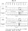
- FIG. 37 illustrates a specific exemplary operation according to the first embodiment of the present invention.
- a UE receives "a UL grant for a UL subframe of CC #2 in SF #n of CC #1" and receives "an activation message that activates the UL grant received in SF #n of CC #1" in SF #(n+6) of CC #1".
- the UE starts to perform a CS operation on CC #2 in the first slot of SF #(n+6).
- This case may be regarded as a kind of the afore-described Case 2.
- the UE receives and decodes the activation message in SF #(n+6) and determines as a result of the CS operation of CC #2 that CC #2 is idle for a time period T.
- the UE transmits a CRTB for a time period from [the start of the first slot of SF #(n+6) + the time taken to receive and decode the activation message + T] to [the end of the first slot of SF #(n+6)] and transmits a PUSCH for a time period from [the start of the second slot of SF #(n+6)] to [the end of the second slot of SF #(n+6)].
- the UE transmits to the eNB 1-bit information about the starting time of the PUSCH transmission (e.g. L_information) (e.g. '1' indicating the start of the (actual) PUSCH transmission at [the start of the second slot of SF #(n+6)]) in PUCCH resources (the second slot) of CC #3 (e.g. the UL PCC) at the starting time of the actual PUSCH transmission (e.g. in the second slot of SF #(n+6)).
- L_information e.g. '1' indicating the start of the (actual) PUSCH transmission at [the start of the second slot of SF #(n+6)]
- the ending time of the PUSCH transmission is [the end of the second slot of SF #(n+6)] according to the preset method of Case 3.
- the UE receives the activation message in SF #(n+6), decodes the activation message, and determines as a result of the CS operation of CC #2 that CC #2 is busy for a preset time period T max . Thus the UE does not transmit a PUSCH in (the second slot of) SF #(n+6).
- the UE may transmit to the eNB 1-bit information about this situation (e.g. '0' indicating no PUSCH transmission in (the second slot of) SF #(n+6)) in PUCCH resources of the second slot (of SF #(n+6)) in CC #3 (e.g. the UL PCC).
- the present invention is not limited thereto.
- a time point before or after the transmission timing of the PUSCH in the SCell, or a preset specific time point may be used in the present invention.
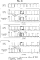
- FIG. 38 illustrates a specific exemplary operation according to the first embodiment of the present invention.
- a UE may receive "a UL grant for a UL subframe of CC #2 in SF #n of CC #1" and may receive "an activation message that activates the UL grant received in SF #n of CC #1" in SF #(n+6) of CC#1".
- SF #h e.g. SF #(n+6)
- This case may be regarded as a kind of the afore-described Case 2.
- the UE receives and decodes the activation message in SF #(n+6) and determines as a result of the CS operation of CC #2 in the first slot of SF #(n+7) that CC #2 is idle for a time period T.
- the UE transmits a CRTB for a time period from [the start of the first slot of SF #(n+7) + T] to [the end of the first slot of SF #(n+7)] and transmits a PUSCH for a time period from [the start of the second slot of SF #(n+7)] to [the end of the second slot of SF #(n+7)].
- the UE transmits to the eNB 1-bit information about the starting time of the PUSCH transmission (e.g. L_information) (e.g. '1' indicating the start of the (actual) PUSCH transmission at [the start of the second slot of SF #(n+7)]) in PUCCH resources (the second slot) of CC #3 (e.g. a UL PCC) at the starting time of the actual PUSCH transmission (e.g. in the second slot of SF #(n+7)).
- L_information e.g. '1' indicating the start of the (actual) PUSCH transmission at [the start of the second slot of SF #(n+7)]
- the ending time of the PUSCH transmission is [the end of the second slot of SF #(n+7)] according to the preset method of Case 3.
- the UE receives the activation message in SF #(n+6), decodes the activation message, and determines as a result of the CS operation of CC #2 in the first slot of SF #(n+7) that CC #2 is busy for the preset time period T max . Thus the UE does not transmit a PUSCH in (the second slot of) SF #(n+7).
- the UE may transmit to the eNB 1-bit information about this situation (e.g. '0' indicating no PUSCH transmission in (the second slot of) SF #(n+7)) in PUCCH resources of the second slot (of SF #(n+7)) in CC #3 (e.g. the UL PCC).
- eNB 1-bit information about this situation e.g. '0' indicating no PUSCH transmission in (the second slot of) SF #(n+7)
- PUCCH resources of the second slot (of SF #(n+7)) in CC #3 e.g. the UL PCC
- the present invention is not limited thereto.
- a time point before or after the transmission timing of the PUSCH in the SCell, or a preset specific time point may be used in the present invention.
- FIG. 39 illustrates a specific exemplary operation according to the first embodiment of the present invention.
- a UE may receive "a UL grant for a UL subframe of CC #2 in SF #n of CC #1" and may receive "an activation message that activates the UL grant received in SF #n of CC #1" in SF #(n+6) of CC #1".
- the UE may start to perform a CS operation on CC #2 in the second slot of SG #(n+6).
- This case may be regarded as a kind of the afore-described Case 2.
- the UE determines as a result of the CS operation of CC #2, starting from the second slot of SF #(n+6) that CC #2 is idle for a time period T.
- the UE transmits a CRTB for a time period from [the start of the second slot of SF #(n+6) + T] to [the end of the second slot of SF #(n+6)] and transmits a PUSCH for a time period from [the start of the first slot of SF #(n+7)] to [the end of the second slot of SF #(n+7)].
- the UE transmits to the eNB 1-bit information about the starting time of the PUSCH transmission (e.g. L_information) (e.g. '1' indicating the start of the (actual) PUSCH transmission at [the start of the first slot of SF #(n+7)]) in PUCCH resources (the first slot) of CC #3 (e.g. a UL PCC) at the starting time of the actual PUSCH transmission (e.g. in the first slot of SF #(n+7)).
- L_information e.g. '1' indicating the start of the (actual) PUSCH transmission at [the start of the first slot of SF #(n+7)]
- the ending time of the PUSCH transmission is [the end of the second slot of SF #(n+7)] according to the preset method of Case 3.
- the UE determines as a result of the CS operation of CC #2, starting from the second slot of SF #(n+6) that CC #2 is busy for the preset time period
- the UE Determining as a result of the CS operation of CC #2 starting from the first slot of SF #(n+7) that CC #2 is idle for the time period T, the UE transmits a CRTB for a time period from [the start of the first slot of SF #(n+7) + T] to [the end of the first slot of SF #(n+7)] and transmits a PUSCH for a time period from [the start of the second slot of SF #(n+7)] to [the end of the second slot of SF #(n+7)].
- the UE transmits to the eNB 1-bit information set to '0' indicating no PUSCH transmission in the first slot of SF #(n+7) in PUCCH resources of the first slot of SF #(n+7) in CC #3 (e.g. the UL PCC) and 1-bit information set to '1' indicating the start of the PUSCH transmission in [the second slot of SF #(n+7)] in PUCCH resources of the second slot of SF #(n+7) in CC #3 (e.g. the UL PCC).
- the ending time of the PUSCH transmission is [the end of the second slot of SF #(n+7)] according to the preset method of Case 3.
- the UE determines as a result of the CS operation of CC #2, starting from the second slot of SF #(n+6) that CC #2 is busy for the preset time period T max . Thus the UE does not transmit a PUSCH in SF #(n+7).
- the UE may transmit to the eNB 1-bit information indicating this situation (e.g. '0' indicating no PUSCH transmission in SF #(n+7)) in PUCCH resources of the first slot (of SF #(n+7)) in CC #3 (e.g. the UL PCC).
- the eNB 1-bit information indicating this situation (e.g. '0' indicating no PUSCH transmission in SF #(n+7)) in PUCCH resources of the first slot (of SF #(n+7)) in CC #3 (e.g. the UL PCC).
- the present invention is not limited thereto.
- a time point before or after the transmission timing of the PUSCH in the SCell, or a preset specific time point may be used in the present invention.
- FIG. 40 illustrates a specific exemplary operation according to the first embodiment of the present invention.
- a "slot offset W" is applied between a PCell (e.g. CC #1 (DL PCell) or CC #3 (UL PCell)) and an SCell (e.g. CC #2).
- a PCell e.g. CC #1 (DL PCell) or CC #3 (UL PCell)
- SCell e.g. CC #2
- An eNB may indicate a value of W to a UE in advance by a higher-layer signal or a physical-layer signal.
- the UE determines as a result of the CS operation of CC #2, starting from the first slot of SF #(n+4) from the viewpoint of SF indexing of CC #2 that CC #2 is idle for a time period T.
- the UE transmits a CRTB for a time period from [the start of the first slot of SF #(n+4) + T] to [the end of the first slot of SF #(n+4)] and transmits a PUSCH for a time period from [the start of the second slot of SF #(n+4)] to [the end of the first slot of SF #(n+5)].
- the UE transmits to the eNB 1-bit information about the starting time of the PUSCH transmission (e.g. L_information) (e.g. '1' indicating the start of the (actual) PUSCH transmission at [the start of the first slot of SF #(n+4) from the viewpoint of SF indexing of CC #3]) in PUCCH resources (the first slot) of CC #3 (e.g. a UL PCC) at the starting time of the actual PUSCH transmission (e.g. in the first slot of SF #(n+4) from the viewpoint of SF indexing of CC #3).
- L_information e.g. '1' indicating the start of the (actual) PUSCH transmission at [the start of the first slot of SF #(n+4) from the viewpoint of SF indexing of CC #3]
- PUCCH resources the first slot of CC #3 (e.g. a UL PCC) at the starting time of the actual PUSCH transmission (e.g. in the first slot of
- the ending time of the PUSCH transmission is [the end of the second slot of SF #(n+4)] from the viewpoint of SF indexing of CC #3 according to the preset method of Case 3.
- the UE determines as a result of the CS operation of CC #2, starting from the first slot of SF #(n+4) from the viewpoint of SF indexing of CC #2 that CC #2 is busy for the preset time period T max .
- the UE discontinues the CS operation in the corresponding slot and then resumes the CS operation, starting from the second slot of SF #(n+4).
- the UE Determining as a result of the CS operation of CC #2 starting from the second slot of SF #(n+4) from the viewpoint of SF indexing of CC #2 that CC #2 is idle for the time period T, the UE transmits a CRTB for a time period from [the start of the second slot of SF #(n+4) + T] to [the end of the second slot of SF #(n+4)] and transmits a PUSCH for a time period from [the start of the first slot of SF #(n+5)] to [the end of the first slot of SF #(n+5)].
- the UE transmits to the eNB 1-bit information set to '0' indicating no PUSCH transmission in the first slot of SF #(n+4) in PUCCH resources of the first slot (of SF #(n+4)) in CC #3 (e.g. the UL PCC) from the viewpoint of SF indexing of CC #3 and 1-bit information set to '1' indicating the start of the PUSCH transmission at [the start of the second slot of SF #(n+4) from the viewpoint of SF indexing of CC #3] in PUCCH resources of the second slot (of SF #(n+4)) in CC #3 (e.g. the UL PCC).
- the ending time of the PUSCH transmission is [the end of the second slot of SF #(n+4) from the viewpoint of SF indexing of CC #3] according to the preset method of Case 3.
- the UE determines as a result of the CS operation of CC #2, starting from the first slot of SF #(n+4) that CC #2 is busy for the preset time period T max .
- the UE does not transmit a PUSCH in SF #(n+4) from the viewpoint of SF indexing of CC #3.
- the UE transmits to the eNB 1-bit information indicating this situation (e.g. '0' indicating no PUSCH transmission in SF #(n+4) from the viewpoint of SF indexing of CC #3) in PUCCH resources of the first slot (of SF #(n+4)) in CC #3 (e.g. the UL PCC) from the viewpoint of SF indexing of CC #3.
- the eNB 1-bit information indicating this situation (e.g. '0' indicating no PUSCH transmission in SF #(n+4) from the viewpoint of SF indexing of CC #3) in PUCCH resources of the first slot (of SF #(n+4)) in CC #3 (e.g. the UL PCC) from the viewpoint of SF indexing of CC #3.
- a "slot offset W" is applied between a PCell (e.g. CC #1 (DL PCell) or CC #3 (UL PCell)) and an SCell (e.g. CC #2), the UE may use one whole subframe for PUSCH transmission after a CS operation.
- a PCell e.g. CC #1 (DL PCell) or CC #3 (UL PCell)
- SCell e.g. CC #2
- Embodiment 1 to Embodiment 8 may be modified and extended in such a manner that a UE transmits a PUSCH immediately when determining CC #2 is idle for a time period T by a CS operation of CC #2, without transmitting a CRTB.
- the UE may not transmit information about "whether a PUSCH is to be transmitted in an SCell" and information about "the starting/ending time of PUSCH transmission” to the eNB in UL resources of a PCell ensuring a transmission opportunity all the time (or at a preset time point). Rather, the UE may use a "known preamble (sequence)" configured to serve this purpose (e.g. to indicate "whether a PUSCH is to be transmitted in an SCell” and "the starting/ending time of PUSCH transmission”), preset between the eNB and the UE.
- a "known preamble (sequence)" configured to serve this purpose (e.g. to indicate "whether a PUSCH is to be transmitted in an SCell” and "the starting/ending time of PUSCH transmission"
- the present invention is not limited thereto.
- a time point before or after the transmission timing of the PUSCH of the SCell, or a preset specific time point may be used in the present invention.
- the foregoing proposed methods may be extended to a CA situation in which two or more CCs are aggregated in an FDD or TDD system.
- the present invention may be extended to a case where specific radio resources (e.g. time/frequency resources) for which a usage is not set are independently used as well as a case where the specific radio resources are aggregated.
- specific radio resources e.g. time/frequency resources
- the present invention may be extended to a case where a (preset) usage of specific resources of each CC used for communication between a transmitter and a receiver is (dynamically) changed according to a system load state in a CA environment.
- the present invention may be extended to any case of PDCCH-based or Enhanced-PDCCH (E-PDCCH)-based communication.
- E-PDCCH Enhanced-PDCCH
- the present invention may be extended to a case where an extension carrier is additionally aggregated for communication.
- the proposed methods may be extended to a case where Device-to-Device (D2D) communication is conducted in a specific frequency band allocated for such a communication usage or existing (cell-specific) radio resources are (re)used by changing the usage of the existing radio resources in a D2D communication environment.
- D2D Device-to-Device
- a BS refers to a terminal node of a network, which directly communicates with a UE.
- a specific operation described as being performed by the BS may be performed by an upper node of the BS. Namely, it is apparent that, in a network comprised of a plurality of network nodes including a BS, various operations performed for communication with a UE may be performed by the BS, or network nodes other than the BS.
- the term 'BS' may be replaced with a fixed station, a Node B, an eNode B (eNB), an access point, etc.
- the term terminal may be replaced with a UE, a Mobile Station (MS), a Mobile Subscriber Station (MSS), etc.
- the embodiments of the present invention may be achieved by various means, for example, hardware, firmware, software, or a combination thereof.
- the methods according to exemplary embodiments of the present invention may be achieved by one or more Application Specific Integrated Circuits (ASICs), Digital Signal Processors (DSPs), Digital Signal Processing Devices (DSPDs), Programmable Logic Devices (PLDs), Field Programmable Gate Arrays (FPGAs), processors, controllers, microcontrollers, microprocessors, etc.
- ASICs Application Specific Integrated Circuits
- DSPs Digital Signal Processors
- DSPDs Digital Signal Processing Devices
- PLDs Programmable Logic Devices
- FPGAs Field Programmable Gate Arrays
- processors controllers, microcontrollers, microprocessors, etc.
- an embodiment of the present invention may be implemented in the form of a module, a procedure, a function, etc.
- Software code may be stored in a memory unit and executed by a processor.
- the memory unit is located at the interior or exterior of the processor and may transmit and receive data to and from the processor via various known means.
Landscapes
- Engineering & Computer Science (AREA)
- Signal Processing (AREA)
- Computer Networks & Wireless Communication (AREA)
- Mobile Radio Communication Systems (AREA)
Claims (10)
- Verfahren zum Senden und Empfangen einer Information mit einer Basisstation, BS, durch ein Benutzergerät, UE, in einem drahtlosen Kommunikationssystem, das Verfahren umfassend:Empfangen einer Downlink-Steuerinformation, DCI, für eine trägerübergreifende Zeitablaufsteuerung von der BS über ein lizenziertes Band unter bedienenden Zellen, die für das UE konfiguriert sind,wobei die DCI eine Information über die Zeitablaufsteuerung eines gemeinsam genutzten physikalischen Uplink-Kanals, PUSCH, durch ein lizenzfreies Band unter den bedienenden Zellenund eine Information über eine Startposition des PUSCH durch das lizenzfreie Band unter den bedienenden Zellen beinhaltet,Durchführen einer Trägererfassung auf dem lizenzfreien Band für eine Zeitdauer, Senden einer zweiten Information über die Startposition des PUSCH an die BS in einer Uplink-Ressource des lizenzierten Bandes undSenden des PUSCH über das lizenzfreie Band basierend auf der DCI, wenn das lizenzfreie Band während der Zeitdauer als inaktiv erfasst wird.
- Verfahren nach Anspruch 1, wobei die zweite Information über die Startposition des PUSCH durch eine Kombination von zwei Bits angegeben wird.
- Verfahren nach Anspruch 2, wobei die zweite Information über die Startposition des PUSCH durch die Kombination der zwei Bits angegeben wird, wenn ein Wert der zwei Bits etwas anderes ist als '00'.
- Verfahren nach Anspruch 1, wobei der PUSCH nicht auf dem lizenzfreien Band gesendet wird, wenn das lizenzfreie Band als während der Zeitdauer aktiv erfasst wird.
- Verfahren nach Anspruch 4, ferner umfassend:
Senden einer Zustandsinformation, die eine Information darüber beinhaltet, dass das lizenzfreie Band als während der Zeitdauer aktiv erfasst wird. - Benutzergerät, UE, zum Senden einer Information an eine Basisstation, BS, in einem drahtlosen Kommunikationssystem, das UE umfassend:einen Prozessor;ein Empfangsmodul, das konfiguriert ist, um eine Downlink-Steuerinformation für eine trägerübergreifende Zeitablaufsteuerung von der BS über ein lizenziertes Band unter bedienenden Zellen, die für das UE konfiguriert sind, zu empfangen,wobei die DCI eine Information über die Zeitablaufsteuerung eines gemeinsam genutzten physikalischen Uplink-Kanals, PUSCH, über eine sekundäre Uplink-Zelle unter den bedienenden Zellen und eine Information über eine Startposition des PUSCH über das lizenzfreie Band unter den bedienenden Zellen beinhaltet,wobei das UE konfiguriert ist, um eine Trägererfassung auf dem lizenzfreien Band für eine Zeitdauer durchzuführenund eine zweite Information über die Startposition des PUSCH an die BS in einer Uplink-Ressource des lizenzierten Bandes zu senden, und das UE ferner ein Sendemodul umfasst, das konfiguriert ist, um den PUSCH über das lizenzfreie Band basierend auf der DCI, wenn das lizenzfreie Band als während der Zeitdauer inaktiv erfasst wird, zu senden.
- UE nach Anspruch 6, wobei die zweite Information über die Startposition des PUSCH durch eine Kombination von zwei Bits angegeben wird.
- UE nach Anspruch 7, wobei die zweite Information über die Startposition des PUSCH durch die Kombination der zwei Bits angegeben wird, wenn ein Wert der zwei Bit etwas anderes ist als '00'.
- UE nach Anspruch 6, wobei der PUSCH nicht auf dem lizenzfreien Band gesendet wird, wenn das lizenzfreie Band als während der Zeitdauer aktiv erfasst wird.
- UE nach Anspruch 9, wobei das Sendemodul konfiguriert ist, um eine Zustandsinformation, die eine Information darüber beinhaltet, dass das lizenzfreie Band als während der Zeitdauer aktiv erfasst wird, zu senden.
Priority Applications (1)
| Application Number | Priority Date | Filing Date | Title |
|---|---|---|---|
| EP19204461.8A EP3621220B1 (de) | 2011-04-19 | 2012-04-19 | Verfahren zur übertragung von steuerungsinformationen in einem drahtlosen kommunikationssystem und vorrichtung dafür |
Applications Claiming Priority (2)
| Application Number | Priority Date | Filing Date | Title |
|---|---|---|---|
| US201161477166P | 2011-04-19 | 2011-04-19 | |
| PCT/KR2012/003005 WO2012144823A2 (ko) | 2011-04-19 | 2012-04-19 | 무선통신 시스템에서의 제어정보의 전송 방법 및 장치 |
Related Child Applications (2)
| Application Number | Title | Priority Date | Filing Date |
|---|---|---|---|
| EP19204461.8A Division EP3621220B1 (de) | 2011-04-19 | 2012-04-19 | Verfahren zur übertragung von steuerungsinformationen in einem drahtlosen kommunikationssystem und vorrichtung dafür |
| EP19204461.8A Division-Into EP3621220B1 (de) | 2011-04-19 | 2012-04-19 | Verfahren zur übertragung von steuerungsinformationen in einem drahtlosen kommunikationssystem und vorrichtung dafür |
Publications (3)
| Publication Number | Publication Date |
|---|---|
| EP2701320A2 EP2701320A2 (de) | 2014-02-26 |
| EP2701320A4 EP2701320A4 (de) | 2015-03-11 |
| EP2701320B1 true EP2701320B1 (de) | 2019-11-27 |
Family
ID=47042051
Family Applications (2)
| Application Number | Title | Priority Date | Filing Date |
|---|---|---|---|
| EP12773941.5A Active EP2701320B1 (de) | 2011-04-19 | 2012-04-19 | Verfahren zur übertragung von steuerungsinformationen in einem drahtlosen kommunikationssystem und vorrichtung dafür |
| EP19204461.8A Active EP3621220B1 (de) | 2011-04-19 | 2012-04-19 | Verfahren zur übertragung von steuerungsinformationen in einem drahtlosen kommunikationssystem und vorrichtung dafür |
Family Applications After (1)
| Application Number | Title | Priority Date | Filing Date |
|---|---|---|---|
| EP19204461.8A Active EP3621220B1 (de) | 2011-04-19 | 2012-04-19 | Verfahren zur übertragung von steuerungsinformationen in einem drahtlosen kommunikationssystem und vorrichtung dafür |
Country Status (4)
| Country | Link |
|---|---|
| US (1) | US9198101B2 (de) |
| EP (2) | EP2701320B1 (de) |
| KR (2) | KR102001930B1 (de) |
| WO (1) | WO2012144823A2 (de) |
Families Citing this family (18)
| Publication number | Priority date | Publication date | Assignee | Title |
|---|---|---|---|---|
| WO2012109195A2 (en) * | 2011-02-07 | 2012-08-16 | Interdigital Patent Holdings, Inc. | Method and apparatus for operating supplementary cells in licensed exempt spectrum |
| JP5895388B2 (ja) * | 2011-07-22 | 2016-03-30 | シャープ株式会社 | 端末装置、基地局装置、集積回路および通信方法 |
| WO2013153515A2 (en) * | 2012-04-09 | 2013-10-17 | Telefonaktiebolaget L M Ericsson (Publ) | Managing uncertain measurement occasions |
| US9949275B2 (en) | 2013-10-01 | 2018-04-17 | Qualcomm Incorporated | Physical uplink control management in LTE/LTE-A systems with unlicensed spectrum |
| KR102087665B1 (ko) * | 2014-04-10 | 2020-03-11 | 삼성전자주식회사 | 셀룰러 무선 통신 시스템에서 비인가 대역 채널을 사용하는 방법 및 장치 |
| US10194424B2 (en) * | 2014-05-20 | 2019-01-29 | Qualcomm Incorporated | Techniques for managing resources for uplink transmissions in a shared radio frequency spectrum band |
| US10193608B2 (en) * | 2014-07-16 | 2019-01-29 | Lg Electronics Inc. | Method for transmitting/receiving channel state information in wireless communication system and device therefor |
| ES2763379T3 (es) | 2015-01-30 | 2020-05-28 | Nec Corp | Método y aparato para realizar transmisión de subtrama fraccional |
| US20180084407A1 (en) * | 2015-04-08 | 2018-03-22 | Lg Electronics Inc. | Method for transmitting sidelink terminal information of terminal in wireless communication system and terminal utilizing the method |
| KR102482083B1 (ko) * | 2015-08-13 | 2022-12-28 | 한국전자통신연구원 | 비면허 대역을 지원하는 통신 네트워크를 위한 스케쥴링 방법 |
| CA2997465C (en) | 2015-09-25 | 2022-07-26 | Panasonic Intellectual Property Corporation Of America | User equipment and wireless communication method |
| WO2017054160A1 (zh) * | 2015-09-30 | 2017-04-06 | 富士通株式会社 | 调度信息确定装置、调度装置、方法和系统 |
| EP3332594A4 (de) * | 2016-02-02 | 2019-03-27 | Nec Corporation | Verfahren und vorrichtungen zur durchführung von uplink-übertragung und -empfang |
| CN108886768B (zh) * | 2016-03-31 | 2020-11-10 | 华为技术有限公司 | 传输数据的方法、基站和用户设备 |
| WO2017170814A1 (ja) * | 2016-03-31 | 2017-10-05 | 株式会社Nttドコモ | ユーザ端末、無線基地局及び無線通信方法 |
| JP6627828B2 (ja) | 2017-07-19 | 2020-01-08 | 日亜化学工業株式会社 | 薄膜の製造方法、薄膜形成材料、光学薄膜、及び光学部材 |
| US10742379B2 (en) | 2018-01-12 | 2020-08-11 | Mediatek Inc. | Uplink control information handling for new radio |
| CN110475345A (zh) * | 2018-05-10 | 2019-11-19 | 中兴通讯股份有限公司 | 数据传输的发送、接收方法及装置 |
Family Cites Families (29)
| Publication number | Priority date | Publication date | Assignee | Title |
|---|---|---|---|---|
| EP1813059B1 (de) * | 2004-10-20 | 2012-06-20 | Qualcomm Incorporated | Mehrfrequenzbandbetrieb in drahtlosen netzwerken |
| US8493873B2 (en) * | 2007-06-18 | 2013-07-23 | Qualcomm Incorporated | Multiplexing of sounding signals in ACK and CQI channels |
| KR20100019948A (ko) * | 2008-08-11 | 2010-02-19 | 엘지전자 주식회사 | 공간 다중화 기법을 이용한 데이터 전송방법 |
| US8577377B2 (en) * | 2009-01-22 | 2013-11-05 | Qualcomm Incorporated | Methods and apparatus for providing a wireless expansion network |
| US8855570B2 (en) * | 2009-02-05 | 2014-10-07 | Telefonaktiebolaget L M Ericsson (Publ) | Coexistence of plural wireless communication transceivers in close proximity |
| KR101670536B1 (ko) | 2009-07-07 | 2016-10-28 | 엘지전자 주식회사 | 다중 반송파 시스템에서 반송파 스케줄링 방법 및 장치 |
| CN102474495B (zh) | 2009-08-17 | 2016-01-20 | Lg电子株式会社 | 在无线通信系统中对发送上行链路控制信息的上行链路载波进行分配的方法及装置 |
| EP3691172B1 (de) * | 2009-10-01 | 2023-12-06 | InterDigital Patent Holdings, Inc. | Uplink-steuerdatenübertragung |
| KR20110036479A (ko) * | 2009-10-01 | 2011-04-07 | 삼성전자주식회사 | 이동통신 시스템에서 harq 피드백을 처리하는 방법 및 장치 |
| EP2502456B1 (de) * | 2009-11-19 | 2020-08-12 | InterDigital Patent Holdings, Inc. | Aktivierung/deaktivierung von komponententrägern in mehrträgersystemen |
| CN102714565B (zh) * | 2010-01-08 | 2016-03-02 | Lg电子株式会社 | 在支持多载波的无线通信系统中发送上行链路控制信息的方法和装置 |
| US20110243106A1 (en) * | 2010-04-02 | 2011-10-06 | Mediatek Inc. | Methods for carrier agggregation |
| EP2562949B1 (de) * | 2010-04-22 | 2020-01-08 | LG Electronics Inc. | Verfahren und vorrichtung zur übertragung von uplink-steuerungsinformationen in einem trägeraggregationssystem |
| US8422429B2 (en) * | 2010-05-04 | 2013-04-16 | Samsung Electronics Co., Ltd. | Method and system for indicating the transmission mode for uplink control information |
| WO2011159624A2 (en) * | 2010-06-18 | 2011-12-22 | Brown, J., Robert, Jr. | System and method for uplink control information transmission in carrier aggregation |
| KR101959362B1 (ko) * | 2010-07-26 | 2019-03-19 | 엘지전자 주식회사 | 무선 통신 시스템에서 상향링크 제어 신호 전송 방법 및 장치 |
| US8873480B2 (en) * | 2010-10-01 | 2014-10-28 | Intel Corporation | Techniques for dynamic spectrum management, allocation, and sharing |
| US8917586B2 (en) * | 2010-10-01 | 2014-12-23 | Blackberry Limited | Orthogonal resource selection transmit diversity and resource assignment |
| WO2012044135A2 (ko) * | 2010-10-01 | 2012-04-05 | 엘지전자 주식회사 | 제어 정보를 전송하는 방법 및 이를 위한 장치 |
| US8885496B2 (en) * | 2010-10-08 | 2014-11-11 | Sharp Kabushiki Kaisha | Uplink control information transmission on backward compatible PUCCH formats with carrier aggregation |
| CN103370970B (zh) * | 2010-11-03 | 2016-11-09 | 三星电子株式会社 | 具有载波聚合的下行链路的tdd系统中的harq-ack信息生成及harq-ack信号功率控制 |
| KR101575442B1 (ko) * | 2010-12-28 | 2015-12-07 | 엘지전자 주식회사 | Tdd 기반 무선 통신 시스템에서 신호 송수신 방법 및 장치 |
| US8817647B2 (en) * | 2011-02-15 | 2014-08-26 | Mediatek Inc. | Priority rules of periodic CSI reporting in carrier aggregation |
| WO2012118343A2 (ko) * | 2011-03-02 | 2012-09-07 | 엘지전자 주식회사 | 단말의 사운딩 참조신호 전송방법 및 장치 |
| WO2012124996A2 (ko) * | 2011-03-15 | 2012-09-20 | 엘지전자 주식회사 | 신호 송수신 방법 및 이를 위한 장치 |
| US9191180B2 (en) * | 2011-03-21 | 2015-11-17 | Lg Electronics Inc. | Method and device for executing HARQ in TDD-based wireless communication system |
| US9467959B2 (en) * | 2011-04-01 | 2016-10-11 | Mediatek, Inc. | Method of maintaining multiple timing advance |
| CN103583071B (zh) * | 2011-04-01 | 2018-02-16 | 英特尔公司 | 在载波聚合通信系统中执行多定时超前调整 |
| US9848411B2 (en) * | 2011-11-17 | 2017-12-19 | Lg Electronics Inc. | Method for transmitting uplink control channel by terminal in wireless communication system |
-
2012
- 2012-04-19 EP EP12773941.5A patent/EP2701320B1/de active Active
- 2012-04-19 EP EP19204461.8A patent/EP3621220B1/de active Active
- 2012-04-19 KR KR1020137024585A patent/KR102001930B1/ko active IP Right Grant
- 2012-04-19 US US14/005,959 patent/US9198101B2/en not_active Expired - Fee Related
- 2012-04-19 WO PCT/KR2012/003005 patent/WO2012144823A2/ko active Application Filing
- 2012-04-19 KR KR1020197020455A patent/KR102131836B1/ko active IP Right Grant
Non-Patent Citations (1)
| Title |
|---|
| None * |
Also Published As
| Publication number | Publication date |
|---|---|
| US9198101B2 (en) | 2015-11-24 |
| KR20140012676A (ko) | 2014-02-03 |
| EP2701320A4 (de) | 2015-03-11 |
| KR20190086055A (ko) | 2019-07-19 |
| WO2012144823A3 (ko) | 2013-01-17 |
| KR102131836B1 (ko) | 2020-07-09 |
| EP3621220A1 (de) | 2020-03-11 |
| KR102001930B1 (ko) | 2019-07-19 |
| WO2012144823A2 (ko) | 2012-10-26 |
| EP2701320A2 (de) | 2014-02-26 |
| US20140029573A1 (en) | 2014-01-30 |
| EP3621220B1 (de) | 2021-03-31 |
Similar Documents
| Publication | Publication Date | Title |
|---|---|---|
| EP2701320B1 (de) | Verfahren zur übertragung von steuerungsinformationen in einem drahtlosen kommunikationssystem und vorrichtung dafür | |
| US10433258B2 (en) | Method and apparatus for transmitting control information in a wireless communication system | |
| US10015819B2 (en) | Method of transmitting control information in a wireless communication system and apparatus thereof | |
| US9763243B2 (en) | Method and apparatus for transmitting control information in wireless communication system | |
| US9763230B2 (en) | Method and apparatus for receiving and transmitting channel state information based on carrier sensing | |
| US9184869B2 (en) | Method and apparatus for transmitting control information in a wireless communication system | |
| US8976751B2 (en) | Method for transmitting control information and apparatus for same | |
| US9380135B2 (en) | Method and device for information transmission in wireless communication system | |
| WO2012169744A2 (ko) | 무선통신 시스템에서의 정보 전송 방법 및 장치 | |
| KR20120081033A (ko) | 무선통신 시스템에서의 제어정보의 전송 방법 및 장치 | |
| US9055573B2 (en) | Method and device for transmitting control information in a wireless communication system | |
| US20130142161A1 (en) | Method and apparatus for transmitting control information in a wireless communication system |
Legal Events
| Date | Code | Title | Description |
|---|---|---|---|
| PUAI | Public reference made under article 153(3) epc to a published international application that has entered the european phase |
Free format text: ORIGINAL CODE: 0009012 |
|
| 17P | Request for examination filed |
Effective date: 20131114 |
|
| AK | Designated contracting states |
Kind code of ref document: A2 Designated state(s): AL AT BE BG CH CY CZ DE DK EE ES FI FR GB GR HR HU IE IS IT LI LT LU LV MC MK MT NL NO PL PT RO RS SE SI SK SM TR |
|
| DAX | Request for extension of the european patent (deleted) | ||
| A4 | Supplementary search report drawn up and despatched |
Effective date: 20150205 |
|
| RIC1 | Information provided on ipc code assigned before grant |
Ipc: H04W 36/08 20090101ALI20150130BHEP Ipc: H04W 72/12 20090101ALI20150130BHEP Ipc: H04J 11/00 20060101AFI20150130BHEP Ipc: H04B 7/26 20060101ALI20150130BHEP |
|
| STAA | Information on the status of an ep patent application or granted ep patent |
Free format text: STATUS: EXAMINATION IS IN PROGRESS |
|
| 17Q | First examination report despatched |
Effective date: 20180528 |
|
| GRAP | Despatch of communication of intention to grant a patent |
Free format text: ORIGINAL CODE: EPIDOSNIGR1 |
|
| STAA | Information on the status of an ep patent application or granted ep patent |
Free format text: STATUS: GRANT OF PATENT IS INTENDED |
|
| INTG | Intention to grant announced |
Effective date: 20190621 |
|
| GRAS | Grant fee paid |
Free format text: ORIGINAL CODE: EPIDOSNIGR3 |
|
| GRAA | (expected) grant |
Free format text: ORIGINAL CODE: 0009210 |
|
| STAA | Information on the status of an ep patent application or granted ep patent |
Free format text: STATUS: THE PATENT HAS BEEN GRANTED |
|
| AK | Designated contracting states |
Kind code of ref document: B1 Designated state(s): AL AT BE BG CH CY CZ DE DK EE ES FI FR GB GR HR HU IE IS IT LI LT LU LV MC MK MT NL NO PL PT RO RS SE SI SK SM TR |
|
| REG | Reference to a national code |
Ref country code: GB Ref legal event code: FG4D |
|
| REG | Reference to a national code |
Ref country code: CH Ref legal event code: EP |
|
| REG | Reference to a national code |
Ref country code: AT Ref legal event code: REF Ref document number: 1207911 Country of ref document: AT Kind code of ref document: T Effective date: 20191215 |
|
| REG | Reference to a national code |
Ref country code: DE Ref legal event code: R096 Ref document number: 602012066040 Country of ref document: DE |
|
| REG | Reference to a national code |
Ref country code: IE Ref legal event code: FG4D |
|
| REG | Reference to a national code |
Ref country code: SE Ref legal event code: TRGR |
|
| REG | Reference to a national code |
Ref country code: NL Ref legal event code: FP |
|
| REG | Reference to a national code |
Ref country code: LT Ref legal event code: MG4D |
|
| PG25 | Lapsed in a contracting state [announced via postgrant information from national office to epo] |
Ref country code: LV Free format text: LAPSE BECAUSE OF FAILURE TO SUBMIT A TRANSLATION OF THE DESCRIPTION OR TO PAY THE FEE WITHIN THE PRESCRIBED TIME-LIMIT Effective date: 20191127 Ref country code: BG Free format text: LAPSE BECAUSE OF FAILURE TO SUBMIT A TRANSLATION OF THE DESCRIPTION OR TO PAY THE FEE WITHIN THE PRESCRIBED TIME-LIMIT Effective date: 20200227 Ref country code: FI Free format text: LAPSE BECAUSE OF FAILURE TO SUBMIT A TRANSLATION OF THE DESCRIPTION OR TO PAY THE FEE WITHIN THE PRESCRIBED TIME-LIMIT Effective date: 20191127 Ref country code: LT Free format text: LAPSE BECAUSE OF FAILURE TO SUBMIT A TRANSLATION OF THE DESCRIPTION OR TO PAY THE FEE WITHIN THE PRESCRIBED TIME-LIMIT Effective date: 20191127 Ref country code: GR Free format text: LAPSE BECAUSE OF FAILURE TO SUBMIT A TRANSLATION OF THE DESCRIPTION OR TO PAY THE FEE WITHIN THE PRESCRIBED TIME-LIMIT Effective date: 20200228 Ref country code: NO Free format text: LAPSE BECAUSE OF FAILURE TO SUBMIT A TRANSLATION OF THE DESCRIPTION OR TO PAY THE FEE WITHIN THE PRESCRIBED TIME-LIMIT Effective date: 20200227 Ref country code: ES Free format text: LAPSE BECAUSE OF FAILURE TO SUBMIT A TRANSLATION OF THE DESCRIPTION OR TO PAY THE FEE WITHIN THE PRESCRIBED TIME-LIMIT Effective date: 20191127 |
|
| PG25 | Lapsed in a contracting state [announced via postgrant information from national office to epo] |
Ref country code: HR Free format text: LAPSE BECAUSE OF FAILURE TO SUBMIT A TRANSLATION OF THE DESCRIPTION OR TO PAY THE FEE WITHIN THE PRESCRIBED TIME-LIMIT Effective date: 20191127 Ref country code: IS Free format text: LAPSE BECAUSE OF FAILURE TO SUBMIT A TRANSLATION OF THE DESCRIPTION OR TO PAY THE FEE WITHIN THE PRESCRIBED TIME-LIMIT Effective date: 20200327 Ref country code: RS Free format text: LAPSE BECAUSE OF FAILURE TO SUBMIT A TRANSLATION OF THE DESCRIPTION OR TO PAY THE FEE WITHIN THE PRESCRIBED TIME-LIMIT Effective date: 20191127 |
|
| PG25 | Lapsed in a contracting state [announced via postgrant information from national office to epo] |
Ref country code: AL Free format text: LAPSE BECAUSE OF FAILURE TO SUBMIT A TRANSLATION OF THE DESCRIPTION OR TO PAY THE FEE WITHIN THE PRESCRIBED TIME-LIMIT Effective date: 20191127 |
|
| PG25 | Lapsed in a contracting state [announced via postgrant information from national office to epo] |
Ref country code: PT Free format text: LAPSE BECAUSE OF FAILURE TO SUBMIT A TRANSLATION OF THE DESCRIPTION OR TO PAY THE FEE WITHIN THE PRESCRIBED TIME-LIMIT Effective date: 20200419 Ref country code: EE Free format text: LAPSE BECAUSE OF FAILURE TO SUBMIT A TRANSLATION OF THE DESCRIPTION OR TO PAY THE FEE WITHIN THE PRESCRIBED TIME-LIMIT Effective date: 20191127 Ref country code: DK Free format text: LAPSE BECAUSE OF FAILURE TO SUBMIT A TRANSLATION OF THE DESCRIPTION OR TO PAY THE FEE WITHIN THE PRESCRIBED TIME-LIMIT Effective date: 20191127 Ref country code: RO Free format text: LAPSE BECAUSE OF FAILURE TO SUBMIT A TRANSLATION OF THE DESCRIPTION OR TO PAY THE FEE WITHIN THE PRESCRIBED TIME-LIMIT Effective date: 20191127 Ref country code: CZ Free format text: LAPSE BECAUSE OF FAILURE TO SUBMIT A TRANSLATION OF THE DESCRIPTION OR TO PAY THE FEE WITHIN THE PRESCRIBED TIME-LIMIT Effective date: 20191127 |
|
| REG | Reference to a national code |
Ref country code: DE Ref legal event code: R097 Ref document number: 602012066040 Country of ref document: DE |
|
| PG25 | Lapsed in a contracting state [announced via postgrant information from national office to epo] |
Ref country code: SM Free format text: LAPSE BECAUSE OF FAILURE TO SUBMIT A TRANSLATION OF THE DESCRIPTION OR TO PAY THE FEE WITHIN THE PRESCRIBED TIME-LIMIT Effective date: 20191127 Ref country code: SK Free format text: LAPSE BECAUSE OF FAILURE TO SUBMIT A TRANSLATION OF THE DESCRIPTION OR TO PAY THE FEE WITHIN THE PRESCRIBED TIME-LIMIT Effective date: 20191127 |
|
| REG | Reference to a national code |
Ref country code: AT Ref legal event code: MK05 Ref document number: 1207911 Country of ref document: AT Kind code of ref document: T Effective date: 20191127 |
|
| PLBE | No opposition filed within time limit |
Free format text: ORIGINAL CODE: 0009261 |
|
| STAA | Information on the status of an ep patent application or granted ep patent |
Free format text: STATUS: NO OPPOSITION FILED WITHIN TIME LIMIT |
|
| 26N | No opposition filed |
Effective date: 20200828 |
|
| PG25 | Lapsed in a contracting state [announced via postgrant information from national office to epo] |
Ref country code: AT Free format text: LAPSE BECAUSE OF FAILURE TO SUBMIT A TRANSLATION OF THE DESCRIPTION OR TO PAY THE FEE WITHIN THE PRESCRIBED TIME-LIMIT Effective date: 20191127 Ref country code: MC Free format text: LAPSE BECAUSE OF FAILURE TO SUBMIT A TRANSLATION OF THE DESCRIPTION OR TO PAY THE FEE WITHIN THE PRESCRIBED TIME-LIMIT Effective date: 20191127 Ref country code: SI Free format text: LAPSE BECAUSE OF FAILURE TO SUBMIT A TRANSLATION OF THE DESCRIPTION OR TO PAY THE FEE WITHIN THE PRESCRIBED TIME-LIMIT Effective date: 20191127 Ref country code: PL Free format text: LAPSE BECAUSE OF FAILURE TO SUBMIT A TRANSLATION OF THE DESCRIPTION OR TO PAY THE FEE WITHIN THE PRESCRIBED TIME-LIMIT Effective date: 20191127 |
|
| REG | Reference to a national code |
Ref country code: CH Ref legal event code: PL |
|
| PG25 | Lapsed in a contracting state [announced via postgrant information from national office to epo] |
Ref country code: CH Free format text: LAPSE BECAUSE OF NON-PAYMENT OF DUE FEES Effective date: 20200430 Ref country code: LI Free format text: LAPSE BECAUSE OF NON-PAYMENT OF DUE FEES Effective date: 20200430 Ref country code: IT Free format text: LAPSE BECAUSE OF FAILURE TO SUBMIT A TRANSLATION OF THE DESCRIPTION OR TO PAY THE FEE WITHIN THE PRESCRIBED TIME-LIMIT Effective date: 20191127 Ref country code: LU Free format text: LAPSE BECAUSE OF NON-PAYMENT OF DUE FEES Effective date: 20200419 |
|
| REG | Reference to a national code |
Ref country code: BE Ref legal event code: MM Effective date: 20200430 |
|
| PG25 | Lapsed in a contracting state [announced via postgrant information from national office to epo] |
Ref country code: BE Free format text: LAPSE BECAUSE OF NON-PAYMENT OF DUE FEES Effective date: 20200430 |
|
| PG25 | Lapsed in a contracting state [announced via postgrant information from national office to epo] |
Ref country code: IE Free format text: LAPSE BECAUSE OF NON-PAYMENT OF DUE FEES Effective date: 20200419 |
|
| PG25 | Lapsed in a contracting state [announced via postgrant information from national office to epo] |
Ref country code: TR Free format text: LAPSE BECAUSE OF FAILURE TO SUBMIT A TRANSLATION OF THE DESCRIPTION OR TO PAY THE FEE WITHIN THE PRESCRIBED TIME-LIMIT Effective date: 20191127 Ref country code: MT Free format text: LAPSE BECAUSE OF FAILURE TO SUBMIT A TRANSLATION OF THE DESCRIPTION OR TO PAY THE FEE WITHIN THE PRESCRIBED TIME-LIMIT Effective date: 20191127 Ref country code: CY Free format text: LAPSE BECAUSE OF FAILURE TO SUBMIT A TRANSLATION OF THE DESCRIPTION OR TO PAY THE FEE WITHIN THE PRESCRIBED TIME-LIMIT Effective date: 20191127 |
|
| PG25 | Lapsed in a contracting state [announced via postgrant information from national office to epo] |
Ref country code: MK Free format text: LAPSE BECAUSE OF FAILURE TO SUBMIT A TRANSLATION OF THE DESCRIPTION OR TO PAY THE FEE WITHIN THE PRESCRIBED TIME-LIMIT Effective date: 20191127 |
|
| PGFP | Annual fee paid to national office [announced via postgrant information from national office to epo] |
Ref country code: FR Payment date: 20230306 Year of fee payment: 12 |
|
| PGFP | Annual fee paid to national office [announced via postgrant information from national office to epo] |
Ref country code: SE Payment date: 20230307 Year of fee payment: 12 |
|
| P01 | Opt-out of the competence of the unified patent court (upc) registered |
Effective date: 20230524 |
|
| PGFP | Annual fee paid to national office [announced via postgrant information from national office to epo] |
Ref country code: DE Payment date: 20230306 Year of fee payment: 12 |
|
| PGFP | Annual fee paid to national office [announced via postgrant information from national office to epo] |
Ref country code: NL Payment date: 20240306 Year of fee payment: 13 |
|
| PGFP | Annual fee paid to national office [announced via postgrant information from national office to epo] |
Ref country code: GB Payment date: 20240305 Year of fee payment: 13 |