EP2701286A2 - Housing for an electric machine with meandering cooling channel and guide structures - Google Patents
Housing for an electric machine with meandering cooling channel and guide structures Download PDFInfo
- Publication number
- EP2701286A2 EP2701286A2 EP13175883.1A EP13175883A EP2701286A2 EP 2701286 A2 EP2701286 A2 EP 2701286A2 EP 13175883 A EP13175883 A EP 13175883A EP 2701286 A2 EP2701286 A2 EP 2701286A2
- Authority
- EP
- European Patent Office
- Prior art keywords
- housing
- webs
- longitudinal axis
- cooling channel
- guide
- Prior art date
- Legal status (The legal status is an assumption and is not a legal conclusion. Google has not performed a legal analysis and makes no representation as to the accuracy of the status listed.)
- Granted
Links
- 238000001816 cooling Methods 0.000 title claims abstract description 110
- 239000012809 cooling fluid Substances 0.000 claims abstract description 51
- 238000000034 method Methods 0.000 claims abstract description 12
- 238000004519 manufacturing process Methods 0.000 claims abstract description 11
- 239000012530 fluid Substances 0.000 claims description 4
- XLYOFNOQVPJJNP-UHFFFAOYSA-N water Substances O XLYOFNOQVPJJNP-UHFFFAOYSA-N 0.000 description 10
- 239000006260 foam Substances 0.000 description 5
- 239000007788 liquid Substances 0.000 description 2
- 238000005476 soldering Methods 0.000 description 2
- 238000009423 ventilation Methods 0.000 description 2
- 238000013022 venting Methods 0.000 description 2
- 238000003466 welding Methods 0.000 description 2
- 229910052782 aluminium Inorganic materials 0.000 description 1
- XAGFODPZIPBFFR-UHFFFAOYSA-N aluminium Chemical compound [Al] XAGFODPZIPBFFR-UHFFFAOYSA-N 0.000 description 1
- 238000005266 casting Methods 0.000 description 1
- 239000002131 composite material Substances 0.000 description 1
- 239000002826 coolant Substances 0.000 description 1
- 239000000110 cooling liquid Substances 0.000 description 1
- 230000001419 dependent effect Effects 0.000 description 1
- 238000004512 die casting Methods 0.000 description 1
- 239000000463 material Substances 0.000 description 1
- 229910052751 metal Inorganic materials 0.000 description 1
- 239000002184 metal Substances 0.000 description 1
- 238000005086 pumping Methods 0.000 description 1
- 238000007528 sand casting Methods 0.000 description 1
- 238000007493 shaping process Methods 0.000 description 1
Images


Classifications
-
- H—ELECTRICITY
- H02—GENERATION; CONVERSION OR DISTRIBUTION OF ELECTRIC POWER
- H02K—DYNAMO-ELECTRIC MACHINES
- H02K5/00—Casings; Enclosures; Supports
- H02K5/04—Casings or enclosures characterised by the shape, form or construction thereof
- H02K5/20—Casings or enclosures characterised by the shape, form or construction thereof with channels or ducts for flow of cooling medium
- H02K5/203—Casings or enclosures characterised by the shape, form or construction thereof with channels or ducts for flow of cooling medium specially adapted for liquids, e.g. cooling jackets
Definitions
- Electric machines can be cooled by liquids, for example.
- a cooling channel may be provided on the housing of the electric machine, in which a cooling fluid flows, for example in the circumferential direction around the electric machine.
- a cooling surface can be increased.
- the flow velocity of the cooling fluid can be increased.
- the cooling fluid may be helically routed around the housing.
- elements such as cooling fins, cooling needles or the like can be incorporated on the housing.
- such housing are made DE 10141890 A1 known.
- an increase in the flow velocity of the cooling fluid can be achieved by alternately deflecting the cooling fluid in the axial direction.
- dead water areas can arise in which, for example, air bubbles can accumulate and which can reduce the cooling efficiency.
- a housing for a fluid-cooled electric machine has an outer meandering surface and an inner meandering surface which form a closed cooling channel. Furthermore, the housing has at least one first meander web and a second meander web, both of which are arranged on the housing or on the cooling channel such that a cooling fluid is guided in a meandering manner. Furthermore, the housing has at least one guide web, which is arranged between the first and the second meander web.
- the idea of the present invention is based on providing additional guide webs between the meander webs, which lead to a splitting of the flow of the cooling fluid in each case between two adjacent meander webs.
- a reduction of dead water areas is achieved.
- the cooling surface of the housing can be increased and thus the cooling efficiency of the housing with the same hydraulic pumping power can be increased by up to about 30 percent.
- a better ventilation of the cooling channel can be ensured.
- the better venting is effected by the fact that the dead water areas, so the areas that are not achieved by the cooling fluid can be reduced and thus accumulate less air or air bubbles in these dead water areas.
- the guide webs are arranged in the cooling channel such that they do not increase or only slightly increase the flow resistance.
- the guide webs ensure a better mechanical rigidity of the housing and optionally a better mechanical stiffness of the mold in the manufacture of the housing.
- the housing can be used, for example, for fluid cooled electric machines such as generators or motors with a stator and a rotor.
- the housing can be used for electric machines in motor vehicles, in particular in hybrid vehicles.
- the housing has a material with good thermal conductivity.
- the housing may comprise a metal such as aluminum.
- the cooling fluid also referred to as coolant, may be a liquid or a gas.
- the cooling fluid may be water.
- the housing may be cylindrical and suitable for receiving a stator and a rotor.
- the housing has an outer circumferential surface and an inner circumferential surface, which together form a closed cooling channel and are preferably made in one piece, that is to say integrally or cohesively.
- the guide webs and possibly also the meander webs can be connected both to the inner circumferential surface and to the outer lateral surface.
- the cooling channel can be designed in two or more parts in the axial direction.
- the inner shell surface and the outer shell surface may be separately, i. be made in two pieces in the radial direction.
- the guide webs and possibly also the meander webs on the inner circumferential surface can be bonded cohesively.
- the outer and the inner circumferential surface of the cooling channel can be designed cylindrically with different diameters.
- the cooling channel can also be referred to as a cooling jacket.
- the housing further has at least one first meander land and at least one second meander land.
- the housing a plurality of first and a plurality of second meandering webs.
- a meandering web can be an elongate element with a longitudinal axis which is directly connected to the edge of the cooling channel.
- the first meander web is directly connected to the edge of a first side of the housing and the second meander web to the edge on the other side of the housing.
- the meandering webs can alternate in the direction of rotation.
- the meander webs can be made in one piece or integrally or cohesively with the lateral surfaces.
- the meandering webs may be alternately arranged on a first and a second edge of the cooling channel and project into the cooling channel. If a longitudinal axis of the housing is arranged, for example, perpendicular to a horizontal, then a first edge of the cooling channel can be arranged at the top and a second edge of the cooling channel at the bottom. For example, a plurality of first meander webs may begin at the first edge of the cooling channel and extend downwardly parallel to the longitudinal axis of the housing. The first meander webs are arranged at a distance from the second edge. The second meander webs can start at the second edge, that is to say at the bottom edge of the cooling channel and run upwards parallel to the longitudinal axis of the housing.
- the first and second meander webs are arranged on the cooling channel such that the cooling fluid is guided meander-shaped in the cooling channel.
- the cooling fluid can be guided by the meander webs alternately at least in sections substantially parallel and antiparallel to the longitudinal axis of the housing.
- Antiparallel means that the flow direction of the cooling fluid is substantially parallel to the longitudinal axis, but in the opposite direction than before. That is, the cooling fluid can be alternately deflected in the axial direction of the housing.
- At least one guide web is provided between the at least one first and the at least one second meander web.
- the guide bar also referred to as a gutter, can be arranged on the housing such that a cooling surface of the housing is increased. The cooling surface is thereby increased, that causes the leadership of the cooling fluid through the guide bar a reduction of dead water areas. That is, with the guide bar is more area achieved by the cooling fluid than without a guide bar.
- the guide bar can be an elongate component with a longitudinal axis. The guide bar is not connected to any of the edges of the cooling channel.
- a guide bar can be provided between each first and second meander web.
- the cooling fluid flows essentially in the circumferential direction and is meandered alternately in the axial direction by the meander webs.
- the cooling fluid can flow around the guide webs on all sides and is thereby divided between two adjacent meander webs into two separate flows, e.g. better to reach corners of the cooling channel.
- the guide bar is designed to divide the cooling fluid into two parallel flows or streams. In this case, both flows are performed parallel or anti-parallel to the longitudinal axis of the housing between the first and the second meandering web.
- the guide web causes a splitting of the flow of the cooling fluid between two adjacent meander webs, so that the cooling fluid flows on both sides of the guide web essentially in the same direction at least in sections and is subsequently brought together again.
- the guide bar is cohesively connected to the outer and the inner circumferential surface. That is, the guide bar is integral or integral with the housing or with the lateral surfaces of the housing.
- the housing for example by means of the lost foam method, which for example DE 102008040873 A1 is known to be produced.
- both the guide bar and the lateral surfaces and possibly also the meander bars form a unit.
- the guide bar can be connected by welding or soldering with the inner and with the outer circumferential surface.
- the first and the second meandering web or the plurality of first and second meandering webs can be made cohesively with the outer and the inner circumferential surface.
- the guide bar may be executed in a multi-part design of the housing, cohesively with one of the lateral surfaces and flush with the abut other lateral surface. Furthermore, in the case of a two-part or multi-part design of the cooling channel, a gap can be provided between the guide web and one of the lateral surfaces.
- a longitudinal axis of the guide web runs essentially parallel to the longitudinal axis of the housing. That is, the guide webs or the longitudinal axes of the guide webs can be oriented axially, that is parallel to the longitudinal axis of the housing. Alternatively or additionally, a longitudinal axis of the first meandering web and a longitudinal axis of the second meandering web are oriented parallel to the longitudinal axis of the housing. For example, both the longitudinal axes of all guide webs and the longitudinal axes of all meander webs may extend parallel to the longitudinal axis of the housing. As a result, an uncomplicated structure of the housing is provided.
- the guide bar or all guide webs may be arranged centrally between each adjacent first and second meandering webs. In this way, a particularly advantageous division of the cooling fluid between the first and the second meander web can be effected, so that as much surface of the housing is achieved by the cooling fluid.
- the longitudinal axis of the guide bar forms an angle with the longitudinal axis of the housing. That is, the longitudinal axis of the guide bar may be set at an angle with respect to an axial direction of the housing. Different guide ribs on the housing can have different angles of inclination.
- the longitudinal axis of a guide bar relative to the longitudinal axis of the housing may be inclined by approximately 30 °.
- a longitudinal axis of another guide bar can be tilted by -30 ° relative to a longitudinal axis of the housing. This means that two guide webs, for example, are arranged mirror-symmetrically to a first meander web and / or a second meander web.
- it can be tilt angle of the guide webs between 0 ° and 30 ° or between 0 ° and -30 °.
- a symmetrical arrangement of the guide webs may be advantageous, since this ensures a direction independent of the flow through the cooling channel.
- the guide webs may be arranged asymmetrically.
- the guide webs can be arranged asymmetrically with respect to the meander webs. That the guide webs may e.g. not centrally located between the right and left Gurandersteg. Additionally or alternatively, the guide webs may be arranged asymmetrically with respect to an axial direction.
- the individual meander loops i. a sequence of guide bar and meander bar be designed differently or asymmetrically. This can simplify the manufacturing process, e.g. For manufacturing reasons, certain webs are possible in one place on the circumference, but not on another, e.g. because of the Entformraum.
- a cross-section of the guide web which is perpendicular to the longitudinal axis of the guide web, varies along the longitudinal axis of the housing. That is, the cross section of the guide bar may change in the axial direction of the housing.
- a guide bar may taper to a direction of the longitudinal axis of the housing and be wider towards the other direction.
- a guide bar can be designed rod-shaped, diamond-shaped or triangular.
- At least one further guide web is provided between the first and the second meander web. That is, between two adjacent meander webs at least two guide webs are arranged. In this case, a distance between the guide webs in each case correspond to the distance of a guide bar to the next meander bar.
- the guide webs between the first and the second meandering web can be arranged parallel to one another. Furthermore, these guide webs may have different lengths and shapes. Furthermore, the guide webs can be arranged at different distances from the first and the second edge of the cooling channel.
- At least two guide webs are connected to one another by deflection webs.
- the deflecting webs can serve as deflection aids.
- the deflection webs can be linear or straight, for example.
- the deflection webs for example, perpendicular to axial direction of the cooling channel.
- the deflecting webs can be rounded or arcuate.
- interruptions are provided in the guide webs and / or in the meander webs.
- the breaks can be e.g. Be openings in which the inner and outer lateral surface are not connected.
- the cooling surface can be increased.
- the interruptions allow an exchange between the individual channels through which the cooling fluid flows.
- the interruptions may be particularly advantageous if the guide webs are connected by means of deflection webs, so that pronounced parallel paths of the cooling liquid arise in the cooling channel.
- the interruptions can produce a pressure equalization between the paths.
- a fluid-cooled electric machine in this case has a stator, a rotor and a housing described above.
- the stator and the rotor are arranged in the housing.
- the housing is designed to cool the stator and / or the rotor by means of a cooling fluid.
- a method of manufacturing a housing as described above comprises the following steps: providing an outer and an inner circumferential surface, which together form a closed cooling channel. Providing at least a first and a second meandering ridge on the housing such that a cooling fluid is alternately guided in parallel and anti-parallel to a longitudinal axis of the housing. Providing a guide bar between the first and the second meandering bar such that the guide bar connects the outer and the inner circumferential surface and increases a cooling surface of the housing.
- a lost-foam method, a welding method or a soldering method can be used for the integral production of the housing.
- the cooling channel is made in one piece.
- the outer circumferential surface and the inner circumferential surface are connected by the guide webs and possibly also by the meander webs materially connected radially. That is, the Leitstege are both with the inner as well as with the outer surface cohesively connected.
- the cooling channel can be produced using a sand casting method, in particular a lost foam method.
- the cooling channel is designed in two parts in the axial direction and in the radial direction.
- the outer circumferential surface and the inner circumferential surface can be materially connected by the guide webs as described above.
- the guide webs and the meander webs can be materially bonded to one of the lateral surfaces.
- the guide webs and the meander webs can be made in one piece with the inner circumferential surface.
- a gap between the outer circumferential surface and the guide webs may be present in the cooling channel.
- the individual parts of the cooling channel may be e.g. Milled, poured and welded.
- the inner circumferential surface can be produced together with the guide webs and the meander webs by a die-casting method and by radial demoulding.
- cooling channel 9 In the figures, only parts of a cooling channel 9 are partially shown. The entire cooling channel 9 can have several, in particular a plurality of meandering turns.
- Fig. 1 the course of flow velocities in the cooling channel 9 of a known housing is shown.
- the cooling channel is a single meander executed.
- the first meander webs 11 are arranged, for example, on a first edge 23 of the cooling channel, and the second meander webs 13 are arranged on a second edge 25 of the cooling channel.
- a cooling fluid flows substantially in the circumferential direction 31 around an in Fig. 1 not shown electric machine.
- the cooling fluid is deflected several times in the axial direction 33. This dead water areas can arise, which are not achieved by the cooling fluid and thus reduce cooling efficiency. Furthermore, air bubbles can accumulate in the dead water areas, which can lead to ventilation problems.
- FIG. 2 an embodiment of the invention is shown in which in the cooling channel 9 of a housing 1 guide webs 17 between the meandering webs 11, 13 are introduced.
- Fig. 2 shows a course of flow velocities of the cooling fluid in the cooling channel 9 in the projection in a plane.
- the cooling efficiency at the same hydraulic pump power for example, be increased by about 30%.
- the increase of the cooling efficiency is due to an enlargement of the cooling surface and the guidance of the flow of the cooling fluid for the reduction of dead water areas.
- the venting of the cooling channel 9 is improved, since now less air or air bubbles can accumulate in the dead water areas.
- the guide webs 17 provided in the cooling channel 9 promote the rigidity of the housing 1, which, for example, in FIG Fig. 9 is shown.
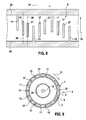
- Fig. 9 shows a cross section of an electric machine 3 with a stator 27 and a rotor 29, which are surrounded by a housing 1.
- the housing has an outer lateral surface 5 and an inner lateral surface 7, which together form a closed cooling channel 9.
- On the housing or on the cooling channel 9 a plurality of first meandering webs 11 and a plurality of second meandering webs 13 is provided.
- a longitudinal axis 15 of the housing 1 is oriented perpendicular to the image plane.
- the first and second meandering webs 11, 13 run as in Fig.
- the meander webs 11, 13 are arranged on the housing 1 in such a way that the cooling fluid is alternately guided parallel and antiparallel to the longitudinal axis 15 of the housing 1. Further, in each case between a first meandering web 11 and a second meandering web 13, a guide web 17 is provided in each case.
- the guide webs 17 connect the outer lateral surface 5 with the inner circumferential surface 7.
- the width of the cooling channel 9 can in the embodiment in Fig. 9 for example, be between 3 and 6 mm. Accordingly, the width of the first meander webs 11, second meander webs 13 and the guide webs 17 can be between 3 and 6 mm.
- the axially projected length of the guide ribs 17 is less than the axial dimension of the cooling channel 9. That is, the guide ribs 17 are connected to neither the first edge 23 nor the second edge 25 of the cooling channel 9. In this way, the cooling fluid can flow past on both sides of the guide bar 17.
- the guide webs 17 can be produced in a casting process, for example in the lost-foam process, and in this way can be materially bonded to the housing.
- a meandering cooling channel 9 with three shaping disks, also referred to as a slice can be produced.
- the introduction of guide webs 17 in the cooling channel 9 or in the housing 1 requires no additional slices. In this way, the manufacturing cost of the housing 1 can be kept low.
- the guide webs 17 or a longitudinal axis 39 of the guide webs 17 are oriented parallel to the first meander webs 11, to the second meander webs 13 and to the axial direction 33 and to the longitudinal axis 15 of the housing 1.
- the guide webs 17 and the longitudinal axis 39 of the guide webs 17 relative to the axial direction 33 may be employed at an angle 19.
- the guide webs 17 close an angle 19 with the projection of the longitudinal axis 15 on the cooling channel 9 a.
- the guide webs 17 may include different angles with the longitudinal axis 15.
- adjacent guide ribs 17 are each arranged mirror-symmetrically to the meander web 11 or the second meander web 13 arranged therebetween.
- a guide bar 17 may enclose an angle of approximately 30 ° with the longitudinal axis 15 of the housing 1.
- One adjacent guide bar 17 may include an angle of -30 ° with the longitudinal axis 15.
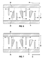
- guide webs 17 may have a variable in the axial direction 33 cross-section. As in 6 and 7 shown, the cross section of the guide ribs 17 changes in the axial direction. In this case, the cross section can vary differently with different guide webs 17.
- the guide bar 17 tapers towards the second edge 25 of the cooling channel.
- the shape of the guide webs 17 corresponds for example to a triangle.
- adjacent guide webs 17 are mirror-symmetrical with respect to the intermediate meander webs 11, 13 executed.
- the guide webs 17 each taper alternately toward the first edge 23 and the second edge 25 of the cooling channel 9.
- a plurality, in particular two guide webs 17 between each two adjacent meandering webs 11 and 13 may be arranged.
- a further guide bar 21 located next to the guide bar 17, a further guide bar 21.
- the guide webs 17, 21 may be offset relative to an axial direction 33 may be arranged. That is, for example, the guide bar 17 is arranged closer to the first edge 23 of the cooling channel 9, while the further guide bar 21 is arranged closer to the second edge 25 of the cooling channel 9.
- Fig. 3 is a plastic representation of the cooling channel 9 of the housing 1 is shown. Only the volume of fluid which can be filled by the cooling fluid is shown.
- the cooling channel may include a cooling fluid supply 35 and a cooling fluid discharge 37. These can be provided as lines in the housing 1.
- Fig. 4 is the flow pattern of an example in Fig. 2 and Fig. 3 shown cooling channels 9 illustrated with arrows. It can be seen that the cooling fluid can flow past the guide bar 17 on four sides.
- the guide bar 17 divides the flow of cooling fluid between two meandering webs 11, 13 into two separate streams, which can then be brought together again. In the illustrated embodiment, the cooling fluid can flow past right and left on the guide bar 17.
- a cooling channel 9 is shown, in which by way of example a guide web 17 is shown with an asymmetrical shape.
- the guide bar 17 in the upper part of a triangular plan and is executed in the lower area linear.
- the remaining guide webs 17 may have a different or different shape.
- a cooling channel 9 is shown with deflecting webs 41.
- the deflecting webs 41 each connect two adjacent guide webs 17 with one another, so that the cooling fluid path separated by the individual guide webs 17 is lengthened in this way.
- the deflection webs 41 are in Fig. 11 executed in a straight line.
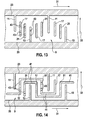
- Fig. 12 is a cooling channel 9 with interruptions 43 to guide webs 17, 21 and shown on meandering webs 13.
- the interruptions 43 may be provided on all guide webs 17, 21 and on all meandering webs 11, 13 or only on selected webs 11, 13, 17, 21.
- the interruptions 43 increase the cooling surface and allow a pressure equalization within the cooling channel 9.
- Fig. 14 is a cooling channel 9 shown, in which both deflecting webs 41 and 43 interruptions are provided in the guide webs 17, 21 combined.
- two guide webs 17, 21 between two adjacent meandering webs 11, 13 are arranged.
- the cooling channel 9 can be as in relation to Fig. 9 already described in one piece. That is, the guide webs 17 and the meander webs 11, 13 are each materially connected both with the inner circumferential surface 7 and with the outer circumferential surface 5. Alternatively, the cooling channel 9 can be designed in several parts. In Fig. 15 the design of the inner circumferential surface 7 is shown at radially two-part design of the cooling channel 9. In this case, the guide webs 17 and the meander webs 11, 13 are integrally connected to the inner circumferential surface 7. In the Fig. 15 not shown outer surface 5 is made separately. In this case, with a composite cooling channel 9, a gap between the guide webs 17 and the outer circumferential surface 5 remain.
Abstract
Description
Elektromaschinen können beispielsweise durch Flüssigkeiten gekühlt werden. Hierzu kann am Gehäuse der Elektromaschine ein Kühlkanal vorgesehen sein, in dem ein Kühlfluid beispielsweise in Umfangrichtung um die Elektromaschine strömt.Electric machines can be cooled by liquids, for example. For this purpose, a cooling channel may be provided on the housing of the electric machine, in which a cooling fluid flows, for example in the circumferential direction around the electric machine.
Um eine Wärmeübertragung von der Elektromaschine auf das Kühlfluid zu erhöhen, kann einerseits eine Kühlfläche vergrößert werden. Andererseits kann hierzu die Strömungsgeschwindigkeit des Kühlfluids vergrößert werden. Um eine Erhöhung der Strömungsgeschwindigkeit zu erreichen, kann das Kühlfluid zum Beispiel helixförmig um das Gehäuse geleitet werden. Ferner können am Gehäuse Elemente wie Kühlrippen, Kühlnadeln oder ähnliches eingebracht sein. Beispielsweise sind derartige Gehäuse aus
Ferner kann eine Erhöhung der Strömungsgeschwindigkeit des Kühlfluids dadurch erreicht werden, dass das Kühlfluid abwechselnd in axialer Richtung umgelenkt wird. Dabei können allerdings sogenannte Totwassergebiete entstehen, in denen sich beispielsweise Luftblasen ansammeln können und die die Kühlungseffizienz verringern können.Furthermore, an increase in the flow velocity of the cooling fluid can be achieved by alternately deflecting the cooling fluid in the axial direction. However, so-called dead water areas can arise in which, for example, air bubbles can accumulate and which can reduce the cooling efficiency.
Es kann daher ein Bedarf an einem verbesserten Gehäuse für eine fluidgekühlte Elektromaschine bestehen, welches insbesondere eine bessere Kühlungseffizienz und eine günstige Herstellung gewährleistet.There may therefore be a need for an improved housing for a fluid cooled electric machine, which in particular ensures better cooling efficiency and production.
Dieser Bedarf kann durch den Gegenstand der vorliegenden Erfindung gemäß den unabhängigen Ansprüchen gedeckt werden. Vorteilhafte Ausführungsformen der vorliegenden Erfindung sind in den abhängigen Ansprüchen beschrieben.This need can be met by the subject matter of the present invention according to the independent claims. Advantageous embodiments of the present invention are described in the dependent claims.
Im Folgenden werden Merkmale, Einzelheiten und mögliche Vorteiler einer Vorrichtung gemäß Ausführungsformen der Erfindung im Detail diskutiert.In the following, features, details and possible advantages of a device according to embodiments of the invention are discussed in detail.
Gemäß einem ersten Aspekt der Erfindung wird ein Gehäuse für eine fluidgekühlte Elektromaschine vorgestellt. Das Gehäuse weist eine äußere Mäanderfläche und eine innere Mäanderfläche auf, die einen geschlossenen Kühlkanal bilden. Ferner weist das Gehäuse mindestens einen ersten Mäandersteg und einen zweiten Mäandersteg auf, die beide derart am Gehäuse bzw. am Kühlkanal angeordnet sind, dass ein Kühlfluid mäanderförmig geführt wird. Des Weiteren weist das Gehäuse mindestens einen Leitsteg auf, der zwischen dem ersten und dem zweiten Mäandersteg angeordnet ist.According to a first aspect of the invention, a housing for a fluid-cooled electric machine is presented. The housing has an outer meandering surface and an inner meandering surface which form a closed cooling channel. Furthermore, the housing has at least one first meander web and a second meander web, both of which are arranged on the housing or on the cooling channel such that a cooling fluid is guided in a meandering manner. Furthermore, the housing has at least one guide web, which is arranged between the first and the second meander web.
Anders ausgedrückt basiert die Idee der vorliegenden Erfindung darauf, zwischen den Mäanderstegen zusätzliche Leitstege vorzusehen, die zu einer Aufspaltung der Strömung des Kühlfluids jeweils zwischen zwei benachbarten Mäanderstegen führt. Durch die Auftrennung der Strömung des Kühlfluids zwischen den Mäanderstegen wird eine Reduzierung von Totwassergebieten erreicht. Auf diese Weise kann die Kühlfläche des Gehäuses vergrößert werden und damit die Kühlungseffizienz des Gehäuses bei gleicher hydraulischer Pumpleistung um bis zu ca. 30 Prozent erhöht werden. Ferner kann dank der verbesserten Führung des Kühlfluids durch die Leitstege eine bessere Entlüftung des Kühlkanals gewährleistet werden. Die bessere Entlüftung wird dadurch bewirkt, dass die Totwassergebiete, also die Gebiete, die nicht durch das Kühlfluid erreicht werden, verringert werden und sich damit weniger Luft bzw. Luftbläschen in diesen Totwassergebieten ansammeln können. Des Weiteren sind die Leitstege derart im Kühlkanal angeordnet, dass sie den Strömungswiderstand nicht oder nur geringfügig erhöhen. Somit wird mit Hilfe der Leitstege bei gleichbleibender Pumpleistung einer Kühlfluidpumpe eine bessere Kühlung erreicht.In other words, the idea of the present invention is based on providing additional guide webs between the meander webs, which lead to a splitting of the flow of the cooling fluid in each case between two adjacent meander webs. By separating the flow of cooling fluid between the meander webs, a reduction of dead water areas is achieved. In this way, the cooling surface of the housing can be increased and thus the cooling efficiency of the housing with the same hydraulic pumping power can be increased by up to about 30 percent. Furthermore, thanks to the improved guidance of the cooling fluid through the guide webs, a better ventilation of the cooling channel can be ensured. The better venting is effected by the fact that the dead water areas, so the areas that are not achieved by the cooling fluid can be reduced and thus accumulate less air or air bubbles in these dead water areas. Furthermore, the guide webs are arranged in the cooling channel such that they do not increase or only slightly increase the flow resistance. Thus, with help the Leitstege at constant pump power of a cooling fluid pump achieved better cooling.
Zusätzlich gewährleisten die Leitstege eine bessere mechanische Steifigkeit des Gehäuses und gegebenenfalls eine bessere mechanische Steifigkeit der Gussform bei der Herstellung des Gehäuses.In addition, the guide webs ensure a better mechanical rigidity of the housing and optionally a better mechanical stiffness of the mold in the manufacture of the housing.
Das Gehäuse kann zum Beispiel für fluidgekühlte Elektromaschinen wie Generatoren oder Motoren mit einem Stator und einem Rotor verwendet werden. Beispielsweise kann das Gehäuse für Elektromaschinen in Kraftfahrzeugen, insbesondere in Hybridfahrzeugen verwendet werden. Dabei weist das Gehäuse ein Material mit guter Wärmeleitfähigkeit auf. Beispielsweise kann das Gehäuse ein Metall wie zum Beispiel Aluminium aufweisen. Ferner kann das Kühlfluid, auch als Kühlmittel bezeichnet, eine Flüssigkeit oder ein Gas sein. Beispielsweise kann das Kühlfluid Wasser sein.The housing can be used, for example, for fluid cooled electric machines such as generators or motors with a stator and a rotor. For example, the housing can be used for electric machines in motor vehicles, in particular in hybrid vehicles. In this case, the housing has a material with good thermal conductivity. For example, the housing may comprise a metal such as aluminum. Further, the cooling fluid, also referred to as coolant, may be a liquid or a gas. For example, the cooling fluid may be water.
Das Gehäuse kann zylinderförmig ausgeführt sein und zur Aufnahme eines Stators und eines Rotors geeignet sein. Hierzu weist das Gehäuse eine äußere Mantelfläche und eine innere Mantelfläche auf, die zusammen einen geschlossenen Kühlkanal bilden und vorzugsweise einstückig, das heißt integral oder stoffschlüssig ausgeführt sind. Dabei können die Leitstege und ggf. auch die Mäanderstege sowohl mit der inneren Mantelfläche als auch mit der äußeren Mantelfläche verbunden sein. Ferner kann der Kühlkanal zwei- bzw. mehrteilig in axialer Richtung ausgeführt sein.The housing may be cylindrical and suitable for receiving a stator and a rotor. For this purpose, the housing has an outer circumferential surface and an inner circumferential surface, which together form a closed cooling channel and are preferably made in one piece, that is to say integrally or cohesively. In this case, the guide webs and possibly also the meander webs can be connected both to the inner circumferential surface and to the outer lateral surface. Furthermore, the cooling channel can be designed in two or more parts in the axial direction.
Alternativ können die innere Mantelfläche und die äußere Mantelfläche separat, d.h. zweistückig in radialer Richtung, gefertigt sein. In diesem Fall können die Leitstege und ggf. auch die Mäanderstege auf der inneren Mantelfläche stoffschlüssig angebunden sein.Alternatively, the inner shell surface and the outer shell surface may be separately, i. be made in two pieces in the radial direction. In this case, the guide webs and possibly also the meander webs on the inner circumferential surface can be bonded cohesively.
Die äußere und die innere Mantelfläche des Kühlkanals können zylinderförmig mit unterschiedlichen Durchmessern ausgeführt sein. Der Kühlkanal kann dabei auch als Kühlmantel bezeichnet werden.The outer and the inner circumferential surface of the cooling channel can be designed cylindrically with different diameters. The cooling channel can also be referred to as a cooling jacket.
Das Gehäuse weist ferner mindestens einen ersten Mäandersteg und mindestens einen zweiten Mäandersteg auf. Insbesondere kann das Gehäuse eine Vielzahl von ersten und eine Vielzahl von zweiten Mäanderstegen aufweisen. Ein Mäandersteg kann dabei ein längliches Element mit einer Längsachse sein, das direkt mit dem Rand des Kühlkanals in Verbindung steht. Dabei ist der erste Mäandersteg mit dem Rand einer ersten Seite des Gehäuses und der zweite Mäandersteg mit dem Rand auf der anderen Seite des Gehäuses direkt verbunden. Die Mäanderstege können sich dabei in Umlaufrichtung abwechseln. Die Mäanderstege können einstückig bzw. integral oder stoffschlüssig mit den Mantelflächen ausgeführt sein.The housing further has at least one first meander land and at least one second meander land. In particular, the housing a plurality of first and a plurality of second meandering webs. A meandering web can be an elongate element with a longitudinal axis which is directly connected to the edge of the cooling channel. In this case, the first meander web is directly connected to the edge of a first side of the housing and the second meander web to the edge on the other side of the housing. The meandering webs can alternate in the direction of rotation. The meander webs can be made in one piece or integrally or cohesively with the lateral surfaces.
Die Mäanderstege können abwechselnd an einem ersten und einem zweiten Rand des Kühlkanals angeordnet sein und in den Kühlkanal hineinragen. Ist eine Längsachse des Gehäuses beispielsweise senkrecht zu einer Horizontalen angeordnet, so kann ein erster Rand des Kühlkanals oben und ein zweiter Rand des Kühlkanals unten angeordnet sein. Eine Vielzahl von ersten Mäanderstegen kann beispielsweise am ersten Rand des Kühlkanals beginnen und parallel zur Längsachse des Gehäuses nach unten verlaufen. Dabei sind die ersten Mäanderstege in einem Abstand vom zweiten Rand angeordnet. Die zweiten Mäanderstege können am zweiten Rand, also am unten befindlichen Rand des Kühlkanals beginnen und parallel zur Längsachse des Gehäuses nach oben verlaufen.The meandering webs may be alternately arranged on a first and a second edge of the cooling channel and project into the cooling channel. If a longitudinal axis of the housing is arranged, for example, perpendicular to a horizontal, then a first edge of the cooling channel can be arranged at the top and a second edge of the cooling channel at the bottom. For example, a plurality of first meander webs may begin at the first edge of the cooling channel and extend downwardly parallel to the longitudinal axis of the housing. The first meander webs are arranged at a distance from the second edge. The second meander webs can start at the second edge, that is to say at the bottom edge of the cooling channel and run upwards parallel to the longitudinal axis of the housing.
Insgesamt sind die ersten und zweiten Mäanderstege derart am Kühlkanal angeordnet, dass das Kühlfluid, mäanderförmig im Kühlkanal geführt wird. Insbesondere kann das Kühlfluid durch die Mäanderstege abwechselnd zumindest abschnittsweise im Wesentlichen parallel und antiparallel zur Längsachse des Gehäuses geführt werden. Antiparallel bedeutet dabei, dass die Strömungsrichtung des Kühlfluids im Wesentlichen parallel zur Längsachse, jedoch in entgegengesetzter Richtung als zuvor verläuft. Das heißt, das Kühlfluid kann abwechselnd in axialer Richtung des Gehäuses umgelenkt werden.Overall, the first and second meander webs are arranged on the cooling channel such that the cooling fluid is guided meander-shaped in the cooling channel. In particular, the cooling fluid can be guided by the meander webs alternately at least in sections substantially parallel and antiparallel to the longitudinal axis of the housing. Antiparallel means that the flow direction of the cooling fluid is substantially parallel to the longitudinal axis, but in the opposite direction than before. That is, the cooling fluid can be alternately deflected in the axial direction of the housing.
Zwischen dem mindestens einen ersten und dem mindestens einen zweiten Mäandersteg ist mindestens ein Leitsteg vorgesehen. Der Leitsteg, auch als Zwischensteg bezeichnet, kann dabei derart am Gehäuse angeordnet sein, dass eine Kühlfläche des Gehäuses vergrößert wird. Die Kühlfläche wird dabei dadurch vergrößert, dass die Führung des Kühlfluids durch den Leitsteg eine Verringerung von Totwassergebieten bewirkt. Das heißt, mit dem Leitsteg wird mehr Fläche durch das Kühlfluid erreicht als ohne einen Leitsteg. Der Leitsteg kann dabei ein längliches Bauelement mit einer Längsachse sein. Dabei ist der Leitsteg mit keinem der Ränder des Kühlkanals verbunden.At least one guide web is provided between the at least one first and the at least one second meander web. The guide bar, also referred to as a gutter, can be arranged on the housing such that a cooling surface of the housing is increased. The cooling surface is thereby increased, that causes the leadership of the cooling fluid through the guide bar a reduction of dead water areas. That is, with the guide bar is more area achieved by the cooling fluid than without a guide bar. The guide bar can be an elongate component with a longitudinal axis. The guide bar is not connected to any of the edges of the cooling channel.
Insbesondere kann zwischen jedem ersten und zweiten Mäandersteg jeweils ein Leitsteg vorgesehen sein. Das Kühlfluid strömt im Wesentlichen in Umfangsrichtung und wird durch die Mäanderstege mäanderförmig abwechselnd in axialer Richtung umgelenkt. Ferner kann das Kühlfluid die Leitstege an allen Seiten umströmen und wird dadurch zwischen zwei benachbarten Mäanderstegen in zwei separate Strömungen aufgeteilt, die z.B. besser Ecken des Kühlkanals erreichen können.In particular, a guide bar can be provided between each first and second meander web. The cooling fluid flows essentially in the circumferential direction and is meandered alternately in the axial direction by the meander webs. Furthermore, the cooling fluid can flow around the guide webs on all sides and is thereby divided between two adjacent meander webs into two separate flows, e.g. better to reach corners of the cooling channel.
Gemäß einem Ausführungsbeispiel der Erfindung ist der Leitsteg ausgeführt, das Kühlfluid in zwei parallele Strömungen bzw. Ströme einzuteilen. Dabei werden beide Strömungen parallel oder antiparallel zur Längsachse des Gehäuses zwischen dem ersten und dem zweiten Mäandersteg geführt. Anders ausgedrückt bewirkt der Leitsteg eine Aufspaltung des Stromes des Kühlfluids zwischen zwei benachbarten Mäanderstegen, so dass das Kühlfluid an beiden Seiten des Leitstegs im Wesentlichen zumindest abschnittsweise in die gleiche Richtung strömt und anschließend wieder zusammengeführt wird.According to one embodiment of the invention, the guide bar is designed to divide the cooling fluid into two parallel flows or streams. In this case, both flows are performed parallel or anti-parallel to the longitudinal axis of the housing between the first and the second meandering web. In other words, the guide web causes a splitting of the flow of the cooling fluid between two adjacent meander webs, so that the cooling fluid flows on both sides of the guide web essentially in the same direction at least in sections and is subsequently brought together again.
Gemäß einem weiteren Ausführungsbeispiel der Erfindung ist der Leitsteg stoffschlüssig mit der äußeren und mit der inneren Mantelfläche verbunden. Das heißt, der Leitsteg ist einstückig bzw. integral mit dem Gehäuse bzw. mit den Mantelflächen des Gehäuses ausgeführt. Hierzu kann das Gehäuse beispielsweise mittels des Lost-Foam-Verfahrens, welches zum Beispiel aus
Alternativ, kann der Leitsteg bei mehrteiliger Ausführung des Gehäuses, stoffschlüssig mit einer der Mantelflächen ausgeführt sein und bündig an der anderen Mantelfläche anliegen. Ferner kann bei einer zwei- oder mehrteiligen Ausgestaltung des Kühlkanals ein Spalt zwischen dem Leitsteg und einer der Mantelflächen vorgesehen sein.Alternatively, the guide bar may be executed in a multi-part design of the housing, cohesively with one of the lateral surfaces and flush with the abut other lateral surface. Furthermore, in the case of a two-part or multi-part design of the cooling channel, a gap can be provided between the guide web and one of the lateral surfaces.
Gemäß einem weiteren Ausführungsbeispiel der Erfindung verläuft eine Längsachse des Leitstegs im Wesentlichen parallel zur Längsachse des Gehäuses. Das heißt, die Leitstege bzw. die Längsachsen der Leitstege können axial, das heißt parallel zur Längsachse des Gehäuses orientiert sein. Alternativ oder zusätzlich ist eine Längsachse des ersten Mäanderstegs und eine Längsachse des zweiten Mäanderstegs parallel zur Längsachse des Gehäuses orientiert. Beispielsweise können sowohl die Längsachsen aller Leitstege als auch die Längsachsen aller Mäanderstege parallel zur Längsachse des Gehäuses verlaufen. Hierdurch wird ein unkomplizierter Aufbau des Gehäuses bereitgestellt.According to a further exemplary embodiment of the invention, a longitudinal axis of the guide web runs essentially parallel to the longitudinal axis of the housing. That is, the guide webs or the longitudinal axes of the guide webs can be oriented axially, that is parallel to the longitudinal axis of the housing. Alternatively or additionally, a longitudinal axis of the first meandering web and a longitudinal axis of the second meandering web are oriented parallel to the longitudinal axis of the housing. For example, both the longitudinal axes of all guide webs and the longitudinal axes of all meander webs may extend parallel to the longitudinal axis of the housing. As a result, an uncomplicated structure of the housing is provided.
Dabei kann der Leitsteg bzw. alle Leitstege mittig jeweils zwischen benachbarten ersten und zweiten Mäanderstegen angeordnet sein. Hierdurch kann eine besonders vorteilhafte Aufteilung des Kühlfluids zwischen dem ersten und dem zweiten Mäandersteg bewirkt werden, so dass möglichst viel Fläche des Gehäuses durch das Kühlfluid erreicht wird.In this case, the guide bar or all guide webs may be arranged centrally between each adjacent first and second meandering webs. In this way, a particularly advantageous division of the cooling fluid between the first and the second meander web can be effected, so that as much surface of the housing is achieved by the cooling fluid.
Gemäß einem weiteren Ausführungsbeispiel der Erfindung schließt die Längsachse des Leitstegs einen Winkel mit der Längsachse des Gehäuses ein. Das heißt, die Längsachse des Leitstegs kann gegenüber einer axialen Richtung des Gehäuses mit einem Winkel angestellt sein. Unterschiedliche Leitstege am Gehäuse können dabei unterschiedliche Neigungswinkel aufweisen. Beispielsweise kann die Längsachse eines Leitstegs gegenüber der Längsachse des Gehäuses um ca. 30° geneigt sein. Eine Längsachse eines weiteren Leitstegs kann dabei um -30° gegenüber einer Längsachse des Gehäuses geneigt sein. Das heißt, dass zwei Leitstege zum Beispiel spiegelsymmetrisch zu einem ersten Mäandersteg und/oder einem zweiten Mäandersteg angeordnet sind. Insbesondere kann er Neigungswinkel der Leitstege zwischen 0° und 30° bzw. zwischen 0° und -30° liegen. Eine symmetrische Anordnung der Leitstege kann vorteilhaft sein, da diese eine Richtungsunabhängigkeit der Durchströmung des Kühlkanals gewährleistet.According to a further embodiment of the invention, the longitudinal axis of the guide bar forms an angle with the longitudinal axis of the housing. That is, the longitudinal axis of the guide bar may be set at an angle with respect to an axial direction of the housing. Different guide ribs on the housing can have different angles of inclination. For example, the longitudinal axis of a guide bar relative to the longitudinal axis of the housing may be inclined by approximately 30 °. A longitudinal axis of another guide bar can be tilted by -30 ° relative to a longitudinal axis of the housing. This means that two guide webs, for example, are arranged mirror-symmetrically to a first meander web and / or a second meander web. In particular, it can be tilt angle of the guide webs between 0 ° and 30 ° or between 0 ° and -30 °. A symmetrical arrangement of the guide webs may be advantageous, since this ensures a direction independent of the flow through the cooling channel.
Alternativ können die Leitstege asymmetrisch angeordnet sein. Dabei können die Leitstege asymmetrisch bezüglich der Mäanderstege angeordnet sein. D.h. die Leitstege können z.B. nicht mittig zwischen dem rechten und dem linken Mäandersteg angeordnet sein. Zusätzlich oder alternativ können die Leitstege asymmetrisch bezüglich einer axialen Richtung angeordnet sein.Alternatively, the guide webs may be arranged asymmetrically. In this case, the guide webs can be arranged asymmetrically with respect to the meander webs. That the guide webs may e.g. not centrally located between the right and left Mäandersteg. Additionally or alternatively, the guide webs may be arranged asymmetrically with respect to an axial direction.
Ferner können die einzelnen Mäanderschleifen, d.h. eine Folge aus Leitsteg und Mäandersteg unterschiedlich bzw. asymmetrisch ausgeführt sein. Dies kann das Herstellungsverfahren vereinfachen, wenn z.B. Fertigungsbedingt bestimmte Stege an einer Stelle am Umfang möglich sind, an einer anderen aber nicht, z.B. wegen der Entformrichtung.Furthermore, the individual meander loops, i. a sequence of guide bar and meander bar be designed differently or asymmetrically. This can simplify the manufacturing process, e.g. For manufacturing reasons, certain webs are possible in one place on the circumference, but not on another, e.g. because of the Entformrichtung.
Gemäß einem weiteren Ausführungsbeispiel der Erfindung variiert ein zur Längsachse des Leitstegs senkrechter Querschnitt des Leitstegs entlang der Längsachse des Gehäuses. Das heißt, der Querschnitt des Leitstegs kann sich in axialer Richtung des Gehäuses ändern. Beispielsweise kann ein Leitsteg sich zu einer Richtung der Längsachse des Gehäuses verjüngen und zur anderen Richtung hin breiter werden. Insbesondere kann ein Leitsteg stabförmig, rautenförmig oder dreieckig ausgeführt sein.According to a further exemplary embodiment of the invention, a cross-section of the guide web, which is perpendicular to the longitudinal axis of the guide web, varies along the longitudinal axis of the housing. That is, the cross section of the guide bar may change in the axial direction of the housing. For example, a guide bar may taper to a direction of the longitudinal axis of the housing and be wider towards the other direction. In particular, a guide bar can be designed rod-shaped, diamond-shaped or triangular.
Gemäß einem weiteren Ausführungsbeispiel der Erfindung ist zwischen dem ersten und dem zweiten Mäandersteg mindestens ein weiterer Leitsteg vorgesehen. Das heißt, zwischen zwei benachbarten Mäanderstegen sind mindestens zwei Leitstege angeordnet. Dabei kann ein Abstand zwischen den Leitstegen jeweils dem Abstand eines Leitstegs zum nächsten Mäandersteg entsprechen. Die Leitstege zwischen dem ersten und dem zweiten Mäandersteg können dabei parallel zueinander angeordnet sein. Ferner können diese Leitstege unterschiedliche Längen und Formen aufweisen. Ferner können die Leitstege in unterschiedlichem Abstand zum ersten und zum zweiten Rand des Kühlkanals angeordnet sein.According to a further embodiment of the invention, at least one further guide web is provided between the first and the second meander web. That is, between two adjacent meander webs at least two guide webs are arranged. In this case, a distance between the guide webs in each case correspond to the distance of a guide bar to the next meander bar. The guide webs between the first and the second meandering web can be arranged parallel to one another. Furthermore, these guide webs may have different lengths and shapes. Furthermore, the guide webs can be arranged at different distances from the first and the second edge of the cooling channel.
Gemäß einem weiteren Ausführungsbeispiel der Erfindung sind mindestens zwei Leitstege durch Umlenkstege miteinander verbunden. Die Umlenkstege können dabei als Umlenkhilfen dienen. Die Umlenkstege können dabei z.B. linienförmig und geradlinig verlaufen. Dabei können die Umlenkstege z.B. senkrecht zur axialen Richtung des Kühlkanals verlaufen. Alternativ können die Umlenkstege abgerundet bzw. bogenförmig ausgeführt sein.According to a further exemplary embodiment of the invention, at least two guide webs are connected to one another by deflection webs. The deflecting webs can serve as deflection aids. The deflection webs can be linear or straight, for example. The deflection webs, for example, perpendicular to axial direction of the cooling channel. Alternatively, the deflecting webs can be rounded or arcuate.
Gemäß einem weiteren Ausführungsbeispiel der Erfindung sind in den Leitstegen und/oder in den Mäanderstegen Unterbrechungen vorgesehen. Die Unterbrechungen können z.B. Öffnungen sein, an denen die innere und die äußere Mantelfläche nicht verbunden sind. Hierdurch kann die Kühloberfläche vergrößert werden. Ferner ermöglichen die Unterbrechungen einen Austausch zwischen den einzelnen durch das Kühlfluid durchströmten Kanälen. Die Unterbrechungen können insbesondere vorteilhaft sein, wenn die Leitstege mittels Umlenkstegen verbunden sind, so dass im Kühlkanal ausgeprägte parallele Pfade der Kühlflüssigkeit entstehen. Die Unterbrechungen können dabei einen Druckausgleich zwischen den Pfaden herstellen.According to a further embodiment of the invention, interruptions are provided in the guide webs and / or in the meander webs. The breaks can be e.g. Be openings in which the inner and outer lateral surface are not connected. As a result, the cooling surface can be increased. Furthermore, the interruptions allow an exchange between the individual channels through which the cooling fluid flows. The interruptions may be particularly advantageous if the guide webs are connected by means of deflection webs, so that pronounced parallel paths of the cooling liquid arise in the cooling channel. The interruptions can produce a pressure equalization between the paths.
Gemäß einem zweiten Aspekt der Erfindung wird eine fluidgekühlte Elektromaschine vorgestellt. Die fluidgekühlte Elektromaschine weist dabei einen Stator, einen Rotor und ein oben beschriebenes Gehäuse auf. Der Stator und der Rotor sind dabei im Gehäuse angeordnet. Das Gehäuse ist dabei ausgeführt, den Stator und/oder den Rotor mittels eines Kühlfluids zu kühlen.According to a second aspect of the invention, a fluid-cooled electric machine is presented. The fluid-cooled electric machine in this case has a stator, a rotor and a housing described above. The stator and the rotor are arranged in the housing. The housing is designed to cool the stator and / or the rotor by means of a cooling fluid.
Gemäß einem dritten Aspekt der Erfindung wird ein Verfahren zur Herstellung eines oben beschriebenen Gehäuses vorgestellt. Das Verfahren weist die folgenden Schritte auf: Bereitstellen einer äußeren und einer inneren Mantelfläche, die zusammen einen geschlossenen Kühlkanal bilden. Vorsehen mindestens eines ersten und eines zweiten Mäanderstegs derart am Gehäuse, dass ein Kühlfluid abwechselnd parallel und antiparallel zu einer Längsachse des Gehäuses geführt wird. Vorsehen eines Leitstegs zwischen dem ersten und dem zweiten Mäandersteg derart, dass der Leitsteg die äußere und die innere Mantelfläche verbindet und eine Kühlfläche des Gehäuses vergrößert. Dabei kann zur integralen Herstellung des Gehäuses ein Lost-Foam-Verfahren, ein Schweißverfahren oder ein Lötverfahren eingesetzt werden.According to a third aspect of the invention, a method of manufacturing a housing as described above is presented. The method comprises the following steps: providing an outer and an inner circumferential surface, which together form a closed cooling channel. Providing at least a first and a second meandering ridge on the housing such that a cooling fluid is alternately guided in parallel and anti-parallel to a longitudinal axis of the housing. Providing a guide bar between the first and the second meandering bar such that the guide bar connects the outer and the inner circumferential surface and increases a cooling surface of the housing. In this case, a lost-foam method, a welding method or a soldering method can be used for the integral production of the housing.
Gemäß einem weiteren Ausführungsbeispiel der Erfindung ist der Kühlkanal einstückig ausgeführt. Anders ausgedrückt sind die äußere Mantelfläche und die innere Mantelfläche durch die Leitstege und gegebenenfalls auch durch die Mäanderstege stoffschlüssig radial verbunden. D.h. die Leitstege sind sowohl mit der inneren als auch mit der äußeren Mantelfläche stoffschlüssig verbunden. Beispielsweise kann der Kühlkanal dabei mit Hilfe eines Sandgussverfahrens, insbesondere eines Lost Foam Verfahrens hergestellt werden.According to a further embodiment of the invention, the cooling channel is made in one piece. In other words, the outer circumferential surface and the inner circumferential surface are connected by the guide webs and possibly also by the meander webs materially connected radially. That is, the Leitstege are both with the inner as well as with the outer surface cohesively connected. For example, the cooling channel can be produced using a sand casting method, in particular a lost foam method.
Gemäß einem weiteren Ausführungsbeispiel der Erfindung ist der Kühlkanal in axialer Richtung und in radialer Richtung zweiteilig ausgeführt. Bei einer zwei- bzw. mehrteiligen Ausführung in axialer Richtung können die äußere Mantelfläche und die innere Mantelfläche wie oben beschrieben stoffschlüssig durch die Leitstege verbunden sein.According to a further embodiment of the invention, the cooling channel is designed in two parts in the axial direction and in the radial direction. In a two- or multi-part design in the axial direction, the outer circumferential surface and the inner circumferential surface can be materially connected by the guide webs as described above.
Bei einer in radialer Richtung zwei- bzw. mehrteiligen Ausführung des Kühlkanals können die Leitstege und die Mäanderstege mit einer der Mantelflächen stoffschlüssig verbunden sein. Beispielsweise können die Leitstege und die Mäanderstege einstückig mit der inneren Mantelfläche gefertigt werden. Dabei kann im Kühlkanal ein Spalt zwischen der äußeren Mantelfläche und den Leitstegen vorliegen. Bei diesem Ausführungsbeispiel können die einzelnen Teile des Kühlkanals z.B. gefräst, gegossen und geschweißt werden. Insbesondere kann die innere Mantelfläche zusammen mit den Leitstegen und den Mäanderstegen durch ein Druckgussverfahren und durch radiale Entformung hergestellt werden.In a two- or multi-part design of the cooling channel in the radial direction, the guide webs and the meander webs can be materially bonded to one of the lateral surfaces. For example, the guide webs and the meander webs can be made in one piece with the inner circumferential surface. In this case, a gap between the outer circumferential surface and the guide webs may be present in the cooling channel. In this embodiment, the individual parts of the cooling channel may be e.g. Milled, poured and welded. In particular, the inner circumferential surface can be produced together with the guide webs and the meander webs by a die-casting method and by radial demoulding.
Weitere Merkmale und Vorteile der vorliegenden Erfindung werden dem Fachmann aus der nachfolgenden Beschreibung beispielhafter Ausführungsformen, die jedoch nicht als die Erfindung beschränkend auszulegen sind, unter Bezugnahme auf die beigelegten Zeichnungen ersichtlich.
- Fig. 1
- zeigt Strömungsgeschwindigkeiten eines Kühlfluids in einem bekannten Einfachmäander in einer Projektion in die Ebene
- Fig. 2
- zeigt Strömungsgeschwindigkeiten eines Kühlfluids in einem Kühlkanal eines Gehäuses gemäß einem Ausführungsbeispiel der Erfindung
- Fig. 3
- zeigt eine plastische Darstellung eines Kühlkanals eines Gehäuses gemäß einem Ausführungsbeispiel der Erfindung
- Fig. 4
- zeigt schematisch einen Strömungsverlauf in einem Kühlkanal eines Gehäuses gemäß einem Ausführungsbeispiel der Erfindung
- Fig. 5
- zeigt einen Kühlkanal eines Gehäuses mit geneigten Leitstegen gemäß einem weiteren Ausführungsbeispiel der Erfindung
- Fig. 6
- zeigt einen Kühlkanal eines Gehäuses mit Leitstegen mit variablem Durchmesser gemäß einem weiteren Ausführungsbeispiel der Erfindung
- Fig. 7
- zeigt einen Kühlkanal eines Gehäuses mit Leitstegen mit variablem Durchmesser gemäß einem weiteren Ausführungsbeispiel der Erfindung
- Fig. 8
- zeigt einen Kühlkanal eines Gehäuses mit jeweils zwei Leitstegen zwischen benachbarten Mäanderstegen gemäß einem weiteren Ausführungsbeispiel der Erfindung
- Fig. 9
- zeigt einen Querschnitt durch eine Elektromaschine gemäß einem Ausführungsbeispiel der Erfindung
- Fig. 10
- zeigt einen Kühlkanal mit einem asymmetrisch ausgestalteten Leitsteg gemäß einem weiteren Ausführungsbeispiel der Erfindung
- Fig. 11
- zeigt einen Kühlkanal mit Umlenkstegen, die Leitstege verbinden gemäß einem weiteren Ausführungsbeispiel der Erfindung
- Fig. 12
- zeigt einen Kühlkanal mit bogenförmigen Umlenkstegen gemäß einem weiteren Ausführungsbeispiel der Erfindung
- Fig. 13
- zeigt einen Kühlkanal mit Unterbrechungen an Leitstegen und an Mäanderstegen gemäß einem weiteren Ausführungsbeispiel der Erfindung
- Fig. 14
- zeigt einen Kühlkanal mit Umlenkstegen und Unterbrechungen gemäß einem weiteren Ausführungsbeispiel der Erfindung
- Fig. 15
- zeigt einen Querschnitt durch eine innere Mantelfläche bei mehrteiliger Ausführung des Kühlkanals gemäß einem Ausführungsbeispiel der Erfindung
- Fig. 1
- shows flow velocities of a cooling fluid in a known simple meander in an in-plane projection
- Fig. 2
- shows flow rates of a cooling fluid in a cooling passage of a housing according to an embodiment of the invention
- Fig. 3
- shows a plastic representation of a cooling passage of a housing according to an embodiment of the invention
- Fig. 4
- schematically shows a flow path in a cooling passage of a housing according to an embodiment of the invention
- Fig. 5
- shows a cooling channel of a housing with inclined guide webs according to another embodiment of the invention
- Fig. 6
- shows a cooling passage of a housing with guide webs of variable diameter according to another embodiment of the invention
- Fig. 7
- shows a cooling passage of a housing with guide webs of variable diameter according to another embodiment of the invention
- Fig. 8
- shows a cooling channel of a housing, each with two guide webs between adjacent meandering webs according to a further embodiment of the invention
- Fig. 9
- shows a cross section through an electric machine according to an embodiment of the invention
- Fig. 10
- shows a cooling channel with an asymmetrically designed guide bar according to another embodiment of the invention
- Fig. 11
- shows a cooling channel with deflection webs connecting the guide webs according to a further embodiment of the invention
- Fig. 12
- shows a cooling channel with arcuate deflection webs according to another embodiment of the invention
- Fig. 13
- shows a cooling channel with interruptions on guide webs and on meandering webs according to a further embodiment of the invention
- Fig. 14
- shows a cooling channel with baffles and interruptions according to another embodiment of the invention
- Fig. 15
- shows a cross section through an inner circumferential surface in multi-part design of the cooling channel according to an embodiment of the invention
Alle Figuren sind lediglich schematische Darstellungen erfindungsgemäßer Vorrichtungen bzw. ihrer Bestandteile gemäß Ausführungsbeispielen der Erfindung. Insbesondere Abstände und Größenrelationen sind in den Figuren nicht maßstabsgetreu wiedergegeben. In den verschiedenen Figuren sind sich entsprechende Elemente mit den gleichen Referenznummern versehen.All figures are merely schematic representations of devices according to the invention or of their components according to embodiments of the invention. In particular, distances and size relationships are not shown to scale in the figures. In the various figures, corresponding elements are provided with the same reference numbers.
In den Figuren sind teilweise lediglich Teile eines Kühlkanals 9 dargestellt. Der gesamte Kühlkanal 9 kann dabei mehrere, insbesondere eine Vielzahl von Mäanderwindungen aufweisen.In the figures, only parts of a
In
In
Das dem Kühlkanal aus
Die Breite des Kühlkanals 9 kann im Ausführungsbeispiel in
Die Leitstege 17 können in einem Gussverfahren, beispielsweise im Lost-Foam-Verfahren hergestellt werden und auf diese Weise stoffschlüssig mit dem Gehäuse verbunden sein. Im Lost-Foam-Verfahren kann ein mäanderförmiger Kühlkanal 9 mit drei Formscheiben, auch als Slice bezeichnet, hergestellt werden. Die Einbringung von Leitstegen 17 in den Kühlkanal 9 bzw. in das Gehäuse 1 erfordert keine zusätzlichen Slices. Auf diese Weise können die Herstellungskosten des Gehäuses 1 gering gehalten werden.The
Im Ausführungsbeispiel in
Ferner können Leitstege 17 einen in axialer Richtung 33 veränderlichen Querschnitt aufweisen. Wie in
Wie in
In
In
In
In
In
Der Kühlkanal 9 kann dabei wie in Bezug auf
Claims (12)
eine äußere und eine innere Mantelfläche (5, 7), die einen geschlossenen Kühlkanal (9) bilden;
mindestens einen ersten und einen zweiten Mäandersteg (11, 13), die derart am Kühlkanal (9) angeordnet sind, dass ein Kühlfluid mäanderförmig im Kühlkanal (9) geführt wird;
dadurch gekennzeichnet, dass
zwischen dem ersten und dem zweiten Mäandersteg (11, 13) ein Leitsteg (17) vorgesehen ist.Housing (1) for a fluid-cooled electric machine (3), comprising the housing (1)
an outer and an inner circumferential surface (5, 7), which form a closed cooling channel (9);
at least a first and a second meandering web (11, 13), which are arranged on the cooling channel (9) such that a cooling fluid is guided meander-shaped in the cooling channel (9);
characterized in that
between the first and the second meander web (11, 13) a guide web (17) is provided.
wobei der Leitsteg (17) ausgeführt ist, das Kühlfluid in zwei parallele Strömungen aufzuteilen, die beide parallel oder antiparallel zur Längsachse (15) des Gehäuses (1) zwischen dem ersten und dem zweiten Mäandersteg (11, 13) geführt sind.Housing (1) according to claim 1,
wherein the guide bar (17) is designed to divide the cooling fluid into two parallel flows, which are both parallel or anti-parallel to the longitudinal axis (15) of the housing (1) between the first and the second meander web (11, 13).
wobei der Leitsteg (17) stoffschlüssig mit der äußeren Mantelfläche (5) und mit der inneren Mantelfläche (7) verbunden ist.Housing (1) according to one of claims 1 and 2,
wherein the guide bar (17) is materially connected to the outer lateral surface (5) and to the inner circumferential surface (7).
wobei eine Längsachse des Leitstegs (17) parallel zur Längsachse (15) des Gehäuses (1) verläuft; und/oder
wobei eine Längsachse des ersten Mäanderstegs (11) und eine Längsachse des zweiten Mäanderstegs (13) parallel zur Längsachse (15) des Gehäuses (1) verlaufen.Housing (1) according to one of claims 1 to 3,
a longitudinal axis of the guide bar (17) extending parallel to the longitudinal axis (15) of the housing (1); and or
wherein a longitudinal axis of the first meandering web (11) and a longitudinal axis of the second meandering web (13) are parallel to the longitudinal axis (15) of the housing (1).
wobei der Leitsteg (17) mittig zwischen dem ersten und dem zweiten Mäandersteg (11, 13) angeordnet ist.Housing (1) according to claim 4,
wherein the guide web (17) is arranged centrally between the first and the second meander web (11, 13).
wobei eine Längsachse des Leitstegs (17) einen Winkel (19) mit der Längsachse (15) des Gehäuses (1) einschließt.Housing (1) according to one of claims 1 to 3,
wherein a longitudinal axis of the guide bar (17) encloses an angle (19) with the longitudinal axis (15) of the housing (1).
wobei ein zur Längsachse (39) des Leitstegs (17) senkrechter Querschnitt des Leitstegs (17) entlang der Längsache des Gehäuses (1) variiert.Housing (1) according to one of claims 1 to 6,
wherein a to the longitudinal axis (39) of the guide bar (17) vertical cross-section of the guide bar (17) along the longitudinal axis of the housing (1) varies.
wobei zwischen dem ersten und dem zweiten Mäandersteg (11, 13) ein weiterer Leitsteg (21) vorgesehen ist;
wobei die Leitstege (17, 21) parallel zueinander angeordnet sind.Housing (1) according to one of claims 1 to 7,
wherein between the first and the second meandering web (11, 13), a further guide web (21) is provided;
wherein the guide webs (17, 21) are arranged parallel to each other.
einen Rotor (29);
ein Gehäuse (1) gemäß einem der Ansprüche 1 bis 8;
wobei der Stator (27) und der Rotor (29) in dem Gehäuse (1) angeordnet sind;
wobei das Gehäuse (1) ausgeführt ist, den Stator (27) und/oder den Rotor (29) mittels eines Kühlfluids zu kühlen.Fluid cooled electric machine (3), the electric machine (3) comprising a stator (27);
a rotor (29);
a housing (1) according to any one of claims 1 to 8;
wherein the stator (27) and the rotor (29) are arranged in the housing (1);
wherein the housing (1) is designed to cool the stator (27) and / or the rotor (29) by means of a cooling fluid.
Vorsehen mindestens eins ersten und eines zweiten Mäanderstegs (11, 13) derart am Kühlkanal (9), dass ein Kühlfluid abwechselnd parallel und antiparallel zu einer Längsachse (15) des Gehäuses (1) geführt wird; Vorsehen eines Leitstegs (17) zwischen dem ersten und dem zweiten Mäandersteg (11, 13).Method for producing a housing (1) according to one of Claims 1 to 8, the method comprising the following steps: providing an outer lateral surface (5) and an inner lateral surface (7) which form a closed cooling channel (9);
Providing at least one first and one second meandering web (11, 13) on the cooling channel (9) in such a way that a cooling fluid is alternately guided parallel and antiparallel to a longitudinal axis (15) of the housing (1); Providing a guide bar (17) between the first and the second meander web (11, 13).
Applications Claiming Priority (1)
| Application Number | Priority Date | Filing Date | Title |
|---|---|---|---|
| DE102012215018.8A DE102012215018A1 (en) | 2012-08-23 | 2012-08-23 | Housing for an electric machine with a meandering cooling channel and guide geometries |
Publications (3)
| Publication Number | Publication Date |
|---|---|
| EP2701286A2 true EP2701286A2 (en) | 2014-02-26 |
| EP2701286A3 EP2701286A3 (en) | 2018-03-28 |
| EP2701286B1 EP2701286B1 (en) | 2020-03-04 |
Family
ID=48782974
Family Applications (1)
| Application Number | Title | Priority Date | Filing Date |
|---|---|---|---|
| EP13175883.1A Active EP2701286B1 (en) | 2012-08-23 | 2013-07-10 | Housing for an electric machine with meandering cooling channel and guide structures |
Country Status (2)
| Country | Link |
|---|---|
| EP (1) | EP2701286B1 (en) |
| DE (1) | DE102012215018A1 (en) |
Cited By (8)
| Publication number | Priority date | Publication date | Assignee | Title |
|---|---|---|---|---|
| CN105743268A (en) * | 2016-03-01 | 2016-07-06 | 哈尔滨理工大学 | Ventilating structure and method for distributing flow of internal and external cooling medium based on loss ratio |
| WO2016062440A3 (en) * | 2014-10-23 | 2016-07-21 | Robert Bosch Gmbh | Fluid-cooled housing for an electrical machine |
| DE102016210302A1 (en) * | 2016-06-10 | 2017-12-14 | Volkswagen Aktiengesellschaft | Cooling structure in a housing or tool |
| CN112134414A (en) * | 2019-06-24 | 2020-12-25 | 法雷奥西门子新能源汽车(德国)有限公司 | Stator housing for an electric machine, electric machine and vehicle |
| US20210401247A1 (en) * | 2020-06-29 | 2021-12-30 | Makita Corporation | Cleaner |
| EP4030595A1 (en) * | 2021-01-18 | 2022-07-20 | Flender GmbH | Dynamoelectric machine with slip ring system cooling |
| US11777365B1 (en) * | 2022-05-23 | 2023-10-03 | Nanchang Sanrui Intelligent Technology Co., Ltd | Motor with flexible variable flow channel |
| CN117254629A (en) * | 2023-11-15 | 2023-12-19 | 广东启新汽车零部件有限公司 | Automobile motor shell |
Families Citing this family (6)
| Publication number | Priority date | Publication date | Assignee | Title |
|---|---|---|---|---|
| DE102014204816A1 (en) * | 2014-03-14 | 2015-09-17 | Zf Friedrichshafen Ag | Electric machine with a cooling element |
| DE102016207232A1 (en) * | 2016-04-28 | 2017-11-02 | Magna powertrain gmbh & co kg | Electric machine |
| JP7088033B2 (en) | 2019-01-08 | 2022-06-21 | 株式会社デンソー | Rotating electric machine |
| DE102020206000A1 (en) | 2019-10-10 | 2021-04-15 | Robert Bosch Gesellschaft mit beschränkter Haftung | Electric machine with bypass cooling duct |
| DE102020208488A1 (en) | 2020-07-07 | 2022-01-13 | Zf Friedrichshafen Ag | Fluid cooling arrangement and electrical machine with a fluid cooling arrangement |
| DE102021201804A1 (en) | 2021-02-25 | 2022-08-25 | Volkswagen Aktiengesellschaft | Housing for an electric machine with a self-venting cooling jacket |
Citations (2)
| Publication number | Priority date | Publication date | Assignee | Title |
|---|---|---|---|---|
| DE10141890A1 (en) | 2001-08-28 | 2003-03-20 | Bosch Gmbh Robert | Electrical generator for automobile, has liquid cooling circuit for stator defined between 2 interfitting housing parts |
| DE102008040873A1 (en) | 2008-07-30 | 2010-02-04 | Robert Bosch Gmbh | Method for producing an electric machine and electric machine for a hybrid vehicle |
Family Cites Families (3)
| Publication number | Priority date | Publication date | Assignee | Title |
|---|---|---|---|---|
| DE202004018968U1 (en) * | 2004-12-08 | 2005-02-10 | Bbt Thermotechnik Gmbh | heat exchangers |
| DE102009001387A1 (en) * | 2009-03-06 | 2010-09-09 | Robert Bosch Gmbh | electric machine |
| AT510749B1 (en) * | 2010-11-18 | 2012-09-15 | Avl List Gmbh | LOBE internal combustion engine |
-
2012
- 2012-08-23 DE DE102012215018.8A patent/DE102012215018A1/en not_active Withdrawn
-
2013
- 2013-07-10 EP EP13175883.1A patent/EP2701286B1/en active Active
Patent Citations (2)
| Publication number | Priority date | Publication date | Assignee | Title |
|---|---|---|---|---|
| DE10141890A1 (en) | 2001-08-28 | 2003-03-20 | Bosch Gmbh Robert | Electrical generator for automobile, has liquid cooling circuit for stator defined between 2 interfitting housing parts |
| DE102008040873A1 (en) | 2008-07-30 | 2010-02-04 | Robert Bosch Gmbh | Method for producing an electric machine and electric machine for a hybrid vehicle |
Cited By (15)
| Publication number | Priority date | Publication date | Assignee | Title |
|---|---|---|---|---|
| WO2016062440A3 (en) * | 2014-10-23 | 2016-07-21 | Robert Bosch Gmbh | Fluid-cooled housing for an electrical machine |
| US10680497B2 (en) | 2014-10-23 | 2020-06-09 | Robert Bosch Gmbh | Fluid-cooled housing for an electrical machine |
| CN105743268A (en) * | 2016-03-01 | 2016-07-06 | 哈尔滨理工大学 | Ventilating structure and method for distributing flow of internal and external cooling medium based on loss ratio |
| CN105743268B (en) * | 2016-03-01 | 2018-05-29 | 哈尔滨理工大学 | A kind of aeration structure and method by cooling medium consumption inside and outside loss ratio distribution |
| DE102016210302A1 (en) * | 2016-06-10 | 2017-12-14 | Volkswagen Aktiengesellschaft | Cooling structure in a housing or tool |
| EP3758197A1 (en) * | 2019-06-24 | 2020-12-30 | Valeo Siemens eAutomotive Germany GmbH | Electric machine, vehicle and stator housing for an electric machine, |
| CN112134414A (en) * | 2019-06-24 | 2020-12-25 | 法雷奥西门子新能源汽车(德国)有限公司 | Stator housing for an electric machine, electric machine and vehicle |
| US11515744B2 (en) * | 2019-06-24 | 2022-11-29 | Valeo Siemens Eautomotive Germany Gmbh | Stator housing for an electric machine, electric machine, and vehicle |
| US20210401247A1 (en) * | 2020-06-29 | 2021-12-30 | Makita Corporation | Cleaner |
| US11744419B2 (en) * | 2020-06-29 | 2023-09-05 | Makita Corporation | Cleaner |
| EP4030595A1 (en) * | 2021-01-18 | 2022-07-20 | Flender GmbH | Dynamoelectric machine with slip ring system cooling |
| WO2022152685A1 (en) * | 2021-01-18 | 2022-07-21 | Flender Gmbh | Dynamoelectric machine having cooling of the slip ring system |
| US11777365B1 (en) * | 2022-05-23 | 2023-10-03 | Nanchang Sanrui Intelligent Technology Co., Ltd | Motor with flexible variable flow channel |
| CN117254629A (en) * | 2023-11-15 | 2023-12-19 | 广东启新汽车零部件有限公司 | Automobile motor shell |
| CN117254629B (en) * | 2023-11-15 | 2024-02-06 | 广东启新汽车零部件有限公司 | Automobile motor shell |
Also Published As
| Publication number | Publication date |
|---|---|
| DE102012215018A1 (en) | 2014-02-27 |
| EP2701286A3 (en) | 2018-03-28 |
| EP2701286B1 (en) | 2020-03-04 |
Similar Documents
| Publication | Publication Date | Title |
|---|---|---|
| EP2701286B1 (en) | Housing for an electric machine with meandering cooling channel and guide structures | |
| EP2688183B1 (en) | Cast electric coil | |
| EP2851118B1 (en) | Device for mixing and for heat exchange and method for its production | |
| DE69915078T2 (en) | ROTATION DEVICE | |
| DE102016216019A1 (en) | Insert for a cooling jacket of an electrical machine | |
| DE2522106B2 (en) | Device for the continuous mixing of flowable substances and method for producing a mixing insert | |
| EP2834906B1 (en) | Electrical machine | |
| WO2018114099A1 (en) | Cooling jacket housing, in particular for an electric machine | |
| DE102013222697A1 (en) | Electric machine with integrated cooling channel in a housing | |
| EP2957024B1 (en) | Centifugal protection of a short circuit ring in induction machines | |
| WO2012136453A2 (en) | Electric machine | |
| DE102014204816A1 (en) | Electric machine with a cooling element | |
| DE602004004270T2 (en) | CASTING MACHINE FOR THE ELECTROMAGNETIC ROTATION OF METAL MELTS MOVING IN THE NOZZLE | |
| EP1241772A1 (en) | Air-cooled electric rotary machine | |
| DE102018203939B4 (en) | Stator for an electrical machine and method for producing a stator for an electrical machine | |
| DE102005030797A1 (en) | Squirrel cage of an induction machine | |
| DE10319230A1 (en) | Piston for internal combustion engine has radially encompassing cooling passage formed in piston crown with rising and falling sections in such way that cooling medium is accelerated from inlet in direction of outlet of passage | |
| DE102023102021A1 (en) | Method for producing a stator and stator | |
| DE102021123317A1 (en) | Housing with a meandering coolant channel for an electrical machine | |
| EP1795281A2 (en) | Mould for continuous casting | |
| EP2620236A2 (en) | Flow-through mould for the strand casting of a strand, especially with billets or bloom profile | |
| DE102016216245A1 (en) | Arrangement for fluid temperature control | |
| EP3574573B1 (en) | Hybrid cage rotor | |
| DE102007032973B4 (en) | Y-shaped cooling fin arrangement | |
| DE102019109721A1 (en) | Rotor for an electric machine |
Legal Events
| Date | Code | Title | Description |
|---|---|---|---|
| PUAI | Public reference made under article 153(3) epc to a published international application that has entered the european phase |
Free format text: ORIGINAL CODE: 0009012 |
|
| AK | Designated contracting states |
Kind code of ref document: A2 Designated state(s): AL AT BE BG CH CY CZ DE DK EE ES FI FR GB GR HR HU IE IS IT LI LT LU LV MC MK MT NL NO PL PT RO RS SE SI SK SM TR |
|
| AX | Request for extension of the european patent |
Extension state: BA ME |
|
| PUAL | Search report despatched |
Free format text: ORIGINAL CODE: 0009013 |
|
| AK | Designated contracting states |
Kind code of ref document: A3 Designated state(s): AL AT BE BG CH CY CZ DE DK EE ES FI FR GB GR HR HU IE IS IT LI LT LU LV MC MK MT NL NO PL PT RO RS SE SI SK SM TR |
|
| AX | Request for extension of the european patent |
Extension state: BA ME |
|
| RIC1 | Information provided on ipc code assigned before grant |
Ipc: H02K 5/20 20060101AFI20180221BHEP |
|
| STAA | Information on the status of an ep patent application or granted ep patent |
Free format text: STATUS: REQUEST FOR EXAMINATION WAS MADE |
|
| 17P | Request for examination filed |
Effective date: 20180928 |
|
| RBV | Designated contracting states (corrected) |
Designated state(s): AL AT BE BG CH CY CZ DE DK EE ES FI FR GB GR HR HU IE IS IT LI LT LU LV MC MK MT NL NO PL PT RO RS SE SI SK SM TR |
|
| STAA | Information on the status of an ep patent application or granted ep patent |
Free format text: STATUS: EXAMINATION IS IN PROGRESS |
|
| 17Q | First examination report despatched |
Effective date: 20190418 |
|
| GRAP | Despatch of communication of intention to grant a patent |
Free format text: ORIGINAL CODE: EPIDOSNIGR1 |
|
| STAA | Information on the status of an ep patent application or granted ep patent |
Free format text: STATUS: GRANT OF PATENT IS INTENDED |
|
| INTG | Intention to grant announced |
Effective date: 20191203 |
|
| GRAS | Grant fee paid |
Free format text: ORIGINAL CODE: EPIDOSNIGR3 |
|
| GRAA | (expected) grant |
Free format text: ORIGINAL CODE: 0009210 |
|
| STAA | Information on the status of an ep patent application or granted ep patent |
Free format text: STATUS: THE PATENT HAS BEEN GRANTED |
|
| AK | Designated contracting states |
Kind code of ref document: B1 Designated state(s): AL AT BE BG CH CY CZ DE DK EE ES FI FR GB GR HR HU IE IS IT LI LT LU LV MC MK MT NL NO PL PT RO RS SE SI SK SM TR |
|
| REG | Reference to a national code |
Ref country code: GB Ref legal event code: FG4D Free format text: NOT ENGLISH |
|
| REG | Reference to a national code |
Ref country code: CH Ref legal event code: EP |
|
| REG | Reference to a national code |
Ref country code: AT Ref legal event code: REF Ref document number: 1241507 Country of ref document: AT Kind code of ref document: T Effective date: 20200315 |
|
| REG | Reference to a national code |
Ref country code: DE Ref legal event code: R096 Ref document number: 502013014372 Country of ref document: DE |
|
| REG | Reference to a national code |
Ref country code: IE Ref legal event code: FG4D Free format text: LANGUAGE OF EP DOCUMENT: GERMAN |
|
| RAP2 | Party data changed (patent owner data changed or rights of a patent transferred) |
Owner name: ROBERT BOSCH GMBH |
|
| PG25 | Lapsed in a contracting state [announced via postgrant information from national office to epo] |
Ref country code: NO Free format text: LAPSE BECAUSE OF FAILURE TO SUBMIT A TRANSLATION OF THE DESCRIPTION OR TO PAY THE FEE WITHIN THE PRESCRIBED TIME-LIMIT Effective date: 20200604 Ref country code: FI Free format text: LAPSE BECAUSE OF FAILURE TO SUBMIT A TRANSLATION OF THE DESCRIPTION OR TO PAY THE FEE WITHIN THE PRESCRIBED TIME-LIMIT Effective date: 20200304 Ref country code: RS Free format text: LAPSE BECAUSE OF FAILURE TO SUBMIT A TRANSLATION OF THE DESCRIPTION OR TO PAY THE FEE WITHIN THE PRESCRIBED TIME-LIMIT Effective date: 20200304 |
|
| REG | Reference to a national code |
Ref country code: NL Ref legal event code: MP Effective date: 20200304 |
|
| PG25 | Lapsed in a contracting state [announced via postgrant information from national office to epo] |
Ref country code: GR Free format text: LAPSE BECAUSE OF FAILURE TO SUBMIT A TRANSLATION OF THE DESCRIPTION OR TO PAY THE FEE WITHIN THE PRESCRIBED TIME-LIMIT Effective date: 20200605 Ref country code: HR Free format text: LAPSE BECAUSE OF FAILURE TO SUBMIT A TRANSLATION OF THE DESCRIPTION OR TO PAY THE FEE WITHIN THE PRESCRIBED TIME-LIMIT Effective date: 20200304 Ref country code: LV Free format text: LAPSE BECAUSE OF FAILURE TO SUBMIT A TRANSLATION OF THE DESCRIPTION OR TO PAY THE FEE WITHIN THE PRESCRIBED TIME-LIMIT Effective date: 20200304 Ref country code: SE Free format text: LAPSE BECAUSE OF FAILURE TO SUBMIT A TRANSLATION OF THE DESCRIPTION OR TO PAY THE FEE WITHIN THE PRESCRIBED TIME-LIMIT Effective date: 20200304 Ref country code: BG Free format text: LAPSE BECAUSE OF FAILURE TO SUBMIT A TRANSLATION OF THE DESCRIPTION OR TO PAY THE FEE WITHIN THE PRESCRIBED TIME-LIMIT Effective date: 20200604 |
|
| REG | Reference to a national code |
Ref country code: LT Ref legal event code: MG4D |
|
| PG25 | Lapsed in a contracting state [announced via postgrant information from national office to epo] |
Ref country code: NL Free format text: LAPSE BECAUSE OF FAILURE TO SUBMIT A TRANSLATION OF THE DESCRIPTION OR TO PAY THE FEE WITHIN THE PRESCRIBED TIME-LIMIT Effective date: 20200304 |
|
| PG25 | Lapsed in a contracting state [announced via postgrant information from national office to epo] |
Ref country code: PT Free format text: LAPSE BECAUSE OF FAILURE TO SUBMIT A TRANSLATION OF THE DESCRIPTION OR TO PAY THE FEE WITHIN THE PRESCRIBED TIME-LIMIT Effective date: 20200729 Ref country code: RO Free format text: LAPSE BECAUSE OF FAILURE TO SUBMIT A TRANSLATION OF THE DESCRIPTION OR TO PAY THE FEE WITHIN THE PRESCRIBED TIME-LIMIT Effective date: 20200304 Ref country code: ES Free format text: LAPSE BECAUSE OF FAILURE TO SUBMIT A TRANSLATION OF THE DESCRIPTION OR TO PAY THE FEE WITHIN THE PRESCRIBED TIME-LIMIT Effective date: 20200304 Ref country code: CZ Free format text: LAPSE BECAUSE OF FAILURE TO SUBMIT A TRANSLATION OF THE DESCRIPTION OR TO PAY THE FEE WITHIN THE PRESCRIBED TIME-LIMIT Effective date: 20200304 Ref country code: SM Free format text: LAPSE BECAUSE OF FAILURE TO SUBMIT A TRANSLATION OF THE DESCRIPTION OR TO PAY THE FEE WITHIN THE PRESCRIBED TIME-LIMIT Effective date: 20200304 Ref country code: LT Free format text: LAPSE BECAUSE OF FAILURE TO SUBMIT A TRANSLATION OF THE DESCRIPTION OR TO PAY THE FEE WITHIN THE PRESCRIBED TIME-LIMIT Effective date: 20200304 Ref country code: EE Free format text: LAPSE BECAUSE OF FAILURE TO SUBMIT A TRANSLATION OF THE DESCRIPTION OR TO PAY THE FEE WITHIN THE PRESCRIBED TIME-LIMIT Effective date: 20200304 Ref country code: IS Free format text: LAPSE BECAUSE OF FAILURE TO SUBMIT A TRANSLATION OF THE DESCRIPTION OR TO PAY THE FEE WITHIN THE PRESCRIBED TIME-LIMIT Effective date: 20200704 Ref country code: SK Free format text: LAPSE BECAUSE OF FAILURE TO SUBMIT A TRANSLATION OF THE DESCRIPTION OR TO PAY THE FEE WITHIN THE PRESCRIBED TIME-LIMIT Effective date: 20200304 |
|
| REG | Reference to a national code |
Ref country code: DE Ref legal event code: R097 Ref document number: 502013014372 Country of ref document: DE |
|
| PLBE | No opposition filed within time limit |
Free format text: ORIGINAL CODE: 0009261 |
|
| STAA | Information on the status of an ep patent application or granted ep patent |
Free format text: STATUS: NO OPPOSITION FILED WITHIN TIME LIMIT |
|
| PG25 | Lapsed in a contracting state [announced via postgrant information from national office to epo] |
Ref country code: DK Free format text: LAPSE BECAUSE OF FAILURE TO SUBMIT A TRANSLATION OF THE DESCRIPTION OR TO PAY THE FEE WITHIN THE PRESCRIBED TIME-LIMIT Effective date: 20200304 |
|
| 26N | No opposition filed |
Effective date: 20201207 |
|
| PG25 | Lapsed in a contracting state [announced via postgrant information from national office to epo] |
Ref country code: PL Free format text: LAPSE BECAUSE OF FAILURE TO SUBMIT A TRANSLATION OF THE DESCRIPTION OR TO PAY THE FEE WITHIN THE PRESCRIBED TIME-LIMIT Effective date: 20200304 Ref country code: SI Free format text: LAPSE BECAUSE OF FAILURE TO SUBMIT A TRANSLATION OF THE DESCRIPTION OR TO PAY THE FEE WITHIN THE PRESCRIBED TIME-LIMIT Effective date: 20200304 Ref country code: MC Free format text: LAPSE BECAUSE OF FAILURE TO SUBMIT A TRANSLATION OF THE DESCRIPTION OR TO PAY THE FEE WITHIN THE PRESCRIBED TIME-LIMIT Effective date: 20200304 |
|
| REG | Reference to a national code |
Ref country code: CH Ref legal event code: PL |
|
| GBPC | Gb: european patent ceased through non-payment of renewal fee |
Effective date: 20200710 |
|
| REG | Reference to a national code |
Ref country code: BE Ref legal event code: MM Effective date: 20200731 |
|
| PG25 | Lapsed in a contracting state [announced via postgrant information from national office to epo] |
Ref country code: GB Free format text: LAPSE BECAUSE OF NON-PAYMENT OF DUE FEES Effective date: 20200710 Ref country code: LU Free format text: LAPSE BECAUSE OF NON-PAYMENT OF DUE FEES Effective date: 20200710 Ref country code: CH Free format text: LAPSE BECAUSE OF NON-PAYMENT OF DUE FEES Effective date: 20200731 Ref country code: LI Free format text: LAPSE BECAUSE OF NON-PAYMENT OF DUE FEES Effective date: 20200731 |
|
| PG25 | Lapsed in a contracting state [announced via postgrant information from national office to epo] |
Ref country code: BE Free format text: LAPSE BECAUSE OF NON-PAYMENT OF DUE FEES Effective date: 20200731 |
|
| PG25 | Lapsed in a contracting state [announced via postgrant information from national office to epo] |
Ref country code: IE Free format text: LAPSE BECAUSE OF NON-PAYMENT OF DUE FEES Effective date: 20200710 |
|
| REG | Reference to a national code |
Ref country code: AT Ref legal event code: MM01 Ref document number: 1241507 Country of ref document: AT Kind code of ref document: T Effective date: 20200710 |
|
| PG25 | Lapsed in a contracting state [announced via postgrant information from national office to epo] |
Ref country code: AT Free format text: LAPSE BECAUSE OF NON-PAYMENT OF DUE FEES Effective date: 20200710 |
|
| PG25 | Lapsed in a contracting state [announced via postgrant information from national office to epo] |
Ref country code: TR Free format text: LAPSE BECAUSE OF FAILURE TO SUBMIT A TRANSLATION OF THE DESCRIPTION OR TO PAY THE FEE WITHIN THE PRESCRIBED TIME-LIMIT Effective date: 20200304 Ref country code: MT Free format text: LAPSE BECAUSE OF FAILURE TO SUBMIT A TRANSLATION OF THE DESCRIPTION OR TO PAY THE FEE WITHIN THE PRESCRIBED TIME-LIMIT Effective date: 20200304 Ref country code: CY Free format text: LAPSE BECAUSE OF FAILURE TO SUBMIT A TRANSLATION OF THE DESCRIPTION OR TO PAY THE FEE WITHIN THE PRESCRIBED TIME-LIMIT Effective date: 20200304 |
|
| PG25 | Lapsed in a contracting state [announced via postgrant information from national office to epo] |
Ref country code: MK Free format text: LAPSE BECAUSE OF FAILURE TO SUBMIT A TRANSLATION OF THE DESCRIPTION OR TO PAY THE FEE WITHIN THE PRESCRIBED TIME-LIMIT Effective date: 20200304 Ref country code: AL Free format text: LAPSE BECAUSE OF FAILURE TO SUBMIT A TRANSLATION OF THE DESCRIPTION OR TO PAY THE FEE WITHIN THE PRESCRIBED TIME-LIMIT Effective date: 20200304 |
|
| PGFP | Annual fee paid to national office [announced via postgrant information from national office to epo] |
Ref country code: IT Payment date: 20230731 Year of fee payment: 11 |
|
| PGFP | Annual fee paid to national office [announced via postgrant information from national office to epo] |
Ref country code: FR Payment date: 20230724 Year of fee payment: 11 Ref country code: DE Payment date: 20230922 Year of fee payment: 11 |