EP2701268A1 - Portable electronic system including charging device and method of charging a secondary battery - Google Patents
Portable electronic system including charging device and method of charging a secondary battery Download PDFInfo
- Publication number
- EP2701268A1 EP2701268A1 EP20120181682 EP12181682A EP2701268A1 EP 2701268 A1 EP2701268 A1 EP 2701268A1 EP 20120181682 EP20120181682 EP 20120181682 EP 12181682 A EP12181682 A EP 12181682A EP 2701268 A1 EP2701268 A1 EP 2701268A1
- Authority
- EP
- European Patent Office
- Prior art keywords
- charging
- voltage
- charging voltage
- battery
- maximum
- Prior art date
- Legal status (The legal status is an assumption and is not a legal conclusion. Google has not performed a legal analysis and makes no representation as to the accuracy of the status listed.)
- Ceased
Links
- 238000007600 charging Methods 0.000 title claims abstract description 374
- 238000000034 method Methods 0.000 title claims description 49
- 230000000391 smoking effect Effects 0.000 claims description 37
- GELKBWJHTRAYNV-UHFFFAOYSA-K lithium iron phosphate Chemical compound [Li+].[Fe+2].[O-]P([O-])([O-])=O GELKBWJHTRAYNV-UHFFFAOYSA-K 0.000 claims description 11
- WHXSMMKQMYFTQS-UHFFFAOYSA-N Lithium Chemical compound [Li] WHXSMMKQMYFTQS-UHFFFAOYSA-N 0.000 claims description 8
- RTAQQCXQSZGOHL-UHFFFAOYSA-N Titanium Chemical compound [Ti] RTAQQCXQSZGOHL-UHFFFAOYSA-N 0.000 claims description 8
- 229910052744 lithium Inorganic materials 0.000 claims description 8
- 229910000625 lithium cobalt oxide Inorganic materials 0.000 claims description 8
- BFZPBUKRYWOWDV-UHFFFAOYSA-N lithium;oxido(oxo)cobalt Chemical compound [Li+].[O-][Co]=O BFZPBUKRYWOWDV-UHFFFAOYSA-N 0.000 claims description 8
- 238000001514 detection method Methods 0.000 claims description 4
- 239000000758 substrate Substances 0.000 description 21
- 241000208125 Nicotiana Species 0.000 description 9
- 235000002637 Nicotiana tabacum Nutrition 0.000 description 9
- 238000010586 diagram Methods 0.000 description 8
- 239000000443 aerosol Substances 0.000 description 7
- 235000019504 cigarettes Nutrition 0.000 description 7
- DNIAPMSPPWPWGF-UHFFFAOYSA-N Propylene glycol Chemical compound CC(O)CO DNIAPMSPPWPWGF-UHFFFAOYSA-N 0.000 description 3
- 238000007599 discharging Methods 0.000 description 3
- 238000010438 heat treatment Methods 0.000 description 3
- 230000003071 parasitic effect Effects 0.000 description 3
- PEDCQBHIVMGVHV-UHFFFAOYSA-N Glycerine Chemical compound OCC(O)CO PEDCQBHIVMGVHV-UHFFFAOYSA-N 0.000 description 2
- 238000013459 approach Methods 0.000 description 2
- 239000007788 liquid Substances 0.000 description 2
- 239000000463 material Substances 0.000 description 2
- 229910000679 solder Inorganic materials 0.000 description 2
- 239000007787 solid Substances 0.000 description 2
- 238000006243 chemical reaction Methods 0.000 description 1
- 150000001875 compounds Chemical class 0.000 description 1
- 238000010277 constant-current charging Methods 0.000 description 1
- 238000011217 control strategy Methods 0.000 description 1
- 230000001419 dependent effect Effects 0.000 description 1
- 239000003571 electronic cigarette Substances 0.000 description 1
- 239000000796 flavoring agent Substances 0.000 description 1
- 235000019634 flavors Nutrition 0.000 description 1
- 239000012634 fragment Substances 0.000 description 1
- 235000011187 glycerol Nutrition 0.000 description 1
- 239000008187 granular material Substances 0.000 description 1
- 230000002427 irreversible effect Effects 0.000 description 1
- 230000002045 lasting effect Effects 0.000 description 1
- 238000005259 measurement Methods 0.000 description 1
- 239000008188 pellet Substances 0.000 description 1
- 239000000843 powder Substances 0.000 description 1
- 239000000779 smoke Substances 0.000 description 1
Images


Classifications
-
- H—ELECTRICITY
- H02—GENERATION; CONVERSION OR DISTRIBUTION OF ELECTRIC POWER
- H02J—CIRCUIT ARRANGEMENTS OR SYSTEMS FOR SUPPLYING OR DISTRIBUTING ELECTRIC POWER; SYSTEMS FOR STORING ELECTRIC ENERGY
- H02J7/00—Circuit arrangements for charging or depolarising batteries or for supplying loads from batteries
- H02J7/34—Parallel operation in networks using both storage and other dc sources, e.g. providing buffering
- H02J7/342—The other DC source being a battery actively interacting with the first one, i.e. battery to battery charging
-
- A—HUMAN NECESSITIES
- A24—TOBACCO; CIGARS; CIGARETTES; SIMULATED SMOKING DEVICES; SMOKERS' REQUISITES
- A24F—SMOKERS' REQUISITES; MATCH BOXES; SIMULATED SMOKING DEVICES
- A24F40/00—Electrically operated smoking devices; Component parts thereof; Manufacture thereof; Maintenance or testing thereof; Charging means specially adapted therefor
- A24F40/50—Control or monitoring
-
- A—HUMAN NECESSITIES
- A24—TOBACCO; CIGARS; CIGARETTES; SIMULATED SMOKING DEVICES; SMOKERS' REQUISITES
- A24F—SMOKERS' REQUISITES; MATCH BOXES; SIMULATED SMOKING DEVICES
- A24F40/00—Electrically operated smoking devices; Component parts thereof; Manufacture thereof; Maintenance or testing thereof; Charging means specially adapted therefor
- A24F40/90—Arrangements or methods specially adapted for charging batteries thereof
- A24F40/95—Arrangements or methods specially adapted for charging batteries thereof structurally associated with cases
-
- H—ELECTRICITY
- H01—ELECTRIC ELEMENTS
- H01M—PROCESSES OR MEANS, e.g. BATTERIES, FOR THE DIRECT CONVERSION OF CHEMICAL ENERGY INTO ELECTRICAL ENERGY
- H01M50/00—Constructional details or processes of manufacture of the non-active parts of electrochemical cells other than fuel cells, e.g. hybrid cells
- H01M50/20—Mountings; Secondary casings or frames; Racks, modules or packs; Suspension devices; Shock absorbers; Transport or carrying devices; Holders
- H01M50/267—Mountings; Secondary casings or frames; Racks, modules or packs; Suspension devices; Shock absorbers; Transport or carrying devices; Holders having means for adapting to batteries or cells of different types or different sizes
-
- H—ELECTRICITY
- H02—GENERATION; CONVERSION OR DISTRIBUTION OF ELECTRIC POWER
- H02J—CIRCUIT ARRANGEMENTS OR SYSTEMS FOR SUPPLYING OR DISTRIBUTING ELECTRIC POWER; SYSTEMS FOR STORING ELECTRIC ENERGY
- H02J7/00—Circuit arrangements for charging or depolarising batteries or for supplying loads from batteries
- H02J7/0029—Circuit arrangements for charging or depolarising batteries or for supplying loads from batteries with safety or protection devices or circuits
- H02J7/0031—Circuit arrangements for charging or depolarising batteries or for supplying loads from batteries with safety or protection devices or circuits using battery or load disconnect circuits
-
- H—ELECTRICITY
- H02—GENERATION; CONVERSION OR DISTRIBUTION OF ELECTRIC POWER
- H02J—CIRCUIT ARRANGEMENTS OR SYSTEMS FOR SUPPLYING OR DISTRIBUTING ELECTRIC POWER; SYSTEMS FOR STORING ELECTRIC ENERGY
- H02J7/00—Circuit arrangements for charging or depolarising batteries or for supplying loads from batteries
- H02J7/0042—Circuit arrangements for charging or depolarising batteries or for supplying loads from batteries characterised by the mechanical construction
- H02J7/0044—Circuit arrangements for charging or depolarising batteries or for supplying loads from batteries characterised by the mechanical construction specially adapted for holding portable devices containing batteries
-
- H—ELECTRICITY
- H02—GENERATION; CONVERSION OR DISTRIBUTION OF ELECTRIC POWER
- H02J—CIRCUIT ARRANGEMENTS OR SYSTEMS FOR SUPPLYING OR DISTRIBUTING ELECTRIC POWER; SYSTEMS FOR STORING ELECTRIC ENERGY
- H02J7/00—Circuit arrangements for charging or depolarising batteries or for supplying loads from batteries
- H02J7/007—Regulation of charging or discharging current or voltage
- H02J7/00712—Regulation of charging or discharging current or voltage the cycle being controlled or terminated in response to electric parameters
- H02J7/007182—Regulation of charging or discharging current or voltage the cycle being controlled or terminated in response to electric parameters in response to battery voltage
-
- H02J7/008—
-
- H—ELECTRICITY
- H04—ELECTRIC COMMUNICATION TECHNIQUE
- H04B—TRANSMISSION
- H04B3/00—Line transmission systems
- H04B3/54—Systems for transmission via power distribution lines
-
- H—ELECTRICITY
- H05—ELECTRIC TECHNIQUES NOT OTHERWISE PROVIDED FOR
- H05B—ELECTRIC HEATING; ELECTRIC LIGHT SOURCES NOT OTHERWISE PROVIDED FOR; CIRCUIT ARRANGEMENTS FOR ELECTRIC LIGHT SOURCES, IN GENERAL
- H05B3/00—Ohmic-resistance heating
- H05B3/02—Details
-
- A—HUMAN NECESSITIES
- A24—TOBACCO; CIGARS; CIGARETTES; SIMULATED SMOKING DEVICES; SMOKERS' REQUISITES
- A24F—SMOKERS' REQUISITES; MATCH BOXES; SIMULATED SMOKING DEVICES
- A24F40/00—Electrically operated smoking devices; Component parts thereof; Manufacture thereof; Maintenance or testing thereof; Charging means specially adapted therefor
- A24F40/20—Devices using solid inhalable precursors
-
- H—ELECTRICITY
- H02—GENERATION; CONVERSION OR DISTRIBUTION OF ELECTRIC POWER
- H02J—CIRCUIT ARRANGEMENTS OR SYSTEMS FOR SUPPLYING OR DISTRIBUTING ELECTRIC POWER; SYSTEMS FOR STORING ELECTRIC ENERGY
- H02J7/00—Circuit arrangements for charging or depolarising batteries or for supplying loads from batteries
- H02J7/0029—Circuit arrangements for charging or depolarising batteries or for supplying loads from batteries with safety or protection devices or circuits
- H02J7/00306—Overdischarge protection
-
- Y—GENERAL TAGGING OF NEW TECHNOLOGICAL DEVELOPMENTS; GENERAL TAGGING OF CROSS-SECTIONAL TECHNOLOGIES SPANNING OVER SEVERAL SECTIONS OF THE IPC; TECHNICAL SUBJECTS COVERED BY FORMER USPC CROSS-REFERENCE ART COLLECTIONS [XRACs] AND DIGESTS
- Y02—TECHNOLOGIES OR APPLICATIONS FOR MITIGATION OR ADAPTATION AGAINST CLIMATE CHANGE
- Y02E—REDUCTION OF GREENHOUSE GAS [GHG] EMISSIONS, RELATED TO ENERGY GENERATION, TRANSMISSION OR DISTRIBUTION
- Y02E60/00—Enabling technologies; Technologies with a potential or indirect contribution to GHG emissions mitigation
- Y02E60/10—Energy storage using batteries
Definitions
- the present invention relates to a portable electronic system including a charger and a secondary device, and to methods for charging and operation of the secondary device.
- the invention may be applied to portable electronic smoking systems.
- Electrically operated smoking systems of the prior art typically include a housing for receiving a smoking article, heating elements to generate an aerosol, a power source and electronic circuitry to control operation of the system.
- Portable electronic smoking devices need to be small and convenient for the user if they are to be widely adopted by smokers of conventional cigarettes. This leads to several technical requirements for the power source of a portable electronic smoking device.
- the power source typically a battery
- the idea of using a rechargeable battery has been suggested in the prior art, but in any commercially viable system the rechargeable battery must be able to deliver enough power for at least one smoking session, must be able to be quickly, safely and conveniently recharged to a level at which it can be reused for another smoking session, and must be operable for thousands of charge cycles.
- One aspect of the disclosure provides a charging device for charging a secondary battery, the charging device comprising:
- the charging profile is split into two parts: a constant current phase and a constant voltage phase.
- the constant current phase the voltage across the secondary battery is adjusted to maintain a constant maximum charging current I ch until the voltage across the battery reaches a defined voltage limit V ch , with I ch and V ch set by the properties of the battery.
- the constant voltage phase the voltage across the battery is maintained at a fixed value V ch until the current drops below a predetermined value I low . For rapid charging it is desirable to maximise the length of the constant current phase.
- the charging circuit formed by the charging device and the secondary battery has an internal resistance both as a result of the components of the charging circuit and the contact resistance between the charging device and the secondary battery. A proportion of the charging voltage supplied by the charging device will be dropped across the internal resistance of the charging circuit, so that the voltage across the secondary battery is less than the charging voltage supplied by the charging device.
- the charging device of the first aspect of the disclosure can provide a charging voltage greater than V ch. By determining the internal resistance of the charging circuit, the amount by which the charging voltage can exceed V ch so that the voltage across the battery is equal to or just less than V ch can be calculated. In this way the charging device supplies a charging voltage that compensates for the voltage drop across the internal resistance of the charging circuit. This increases the duration of the constant current charging phase because determining the cut off voltage V ch at the battery rather than at the voltage regulator means the cut off voltage is reached later.
- the internal resistance of the charging circuit changes over time.
- the internal resistance of the battery increases with the life of the battery.
- the contact resistance between the charging device and the secondary battery may also change over time and will vary from charger to charger and battery to battery.
- the charging device of the first aspect of the disclosure is configured to determine the internal resistance of the charging circuit during every charging cycle to ensure that the length of the constant current portion of the charging cycle is maximised.
- the microprocessor may be configured to limit the charging voltage supplied by the voltage regulator so that a voltage received by the secondary battery is equal to a predetermined maximum voltage, V ch .
- the second charging voltage is preferably non-zero and may have a predetermined voltage difference from the first charging voltage.
- the second charging voltage may be a predetermined non-zero voltage. With the second charging voltage non-zero, there is never any interruption to the charging process, which would lengthen the charge time.
- the microprocessor may be configured to adjust the first charging voltage to maintain a constant charging current in the charging circuit until the charging voltage exceeds a maximum charging voltage, the maximum charging voltage calculated based on the characteristics of the secondary battery and the determined internal resistance of the charging circuit.
- the microprocessor may be configured to calculate the maximum voltage and adjust the first charging voltage to maintain it at a level at or below the maximum charging voltage a plurality of times during a single charging cycle. Rather than simply supplying a constant charging voltage during a constant voltage phase, it is advantageous to provide an adjusted charging voltage that compensates for the voltage dropped across the internal resistance of the charging circuit. As the secondary battery approaches a fully charged level, the charging current for a given charging voltage falls. As a result, the voltage dropped across the internal resistance of the charging circuit falls. This in turn means that the charging voltage required to be supplied by the voltage regulator to ensure that the voltage across the battery is equal to V ch falls.
- the microprocessor may be configured to continuously or periodically recalculate the maximum voltage and adjust the first charging voltage to maintain it at a level at or below the maximum charging voltage after the first charging voltage first reaches the maximum charging voltage during a single charging cycle.
- the microprocessor may be configured to determine the internal resistance and calculate the maximum charging voltage only after the first charging voltage has reached a predetermined voltage level.
- the predetermined voltage level may be V ch , the maximum battery voltage.
- a method of charging a secondary battery comprising:
- the second charging voltage is preferably non-zero and may have a predetermined voltage difference from the first charging voltage.
- the steps of calculating the maximum voltage and adjusting the first charging voltage to maintain it at a level at or below the maximum charging voltage may be carried out a plurality of times during a single charging cycle.
- the steps of calculating the maximum voltage and adjusting the first charging voltage to maintain it at a level at or below the maximum charging voltage may be carried out continuously after the first charging voltage first reaches the maximum charging voltage during a single charging cycle.
- the step of determining the internal resistance may be carried out periodically during a charging cycle.
- the steps of determining the internal resistance and calculating the maximum charging voltage may be carried only after the first charging voltage has reached a predetermined voltage level.
- the predetermined voltage level may be V ch , the maximum battery voltage.
- a charging device comprising:
- the microprocessor is configured to continuously or periodically recalculate the maximum voltage and adjust the first charging voltage to maintain it at a level at or below the maximum charging voltage after the first charging voltage first reaches the maximum charging voltage.
- the step of determining the internal resistance may comprise measuring the internal resistance or estimating the internal resistance.
- a method of charging a secondary battery comprising:
- the charging device and method in accordance with the first, second, third and fourth aspects of the disclosure may be applied to electronic smoking systems.
- the charging device may be used to charge a secondary battery in an electronic smoking device.
- the electronic smoking device may include an electrically powered heater configured to heat an aerosol-forming substrate.
- the aerosol-forming substrate may be provided in the form of a cigarette having a mouthpiece portion on which an end user inhales.
- the secondary battery may advantageously provide sufficient power for a single smoking session, exhausting a single aerosol-forming substrate.
- a short recharging time is crucial for the acceptance of electronic cigarettes.
- the charging device and charging method of the present disclosure maximise the duration of a constant current phase of the recharging process and also maximise the voltage across the secondary battery when the constant current phase has ended.
- a portable electrical system comprising primary and secondary devices, the primary device having a first, lithium cobalt oxide battery and the secondary device having a second, lithium iron phosphate or lithium titanate battery, wherein the primary and secondary devices are configured to allow recharging of the second battery from the first battery.
- the secondary device may be an electrically heated smoking device.
- the electrically heated smoking device may comprise an electrical heater powered by the second battery.
- the electrical heater may be configured to heat an aerosol-forming substrate.
- the primary device may be a portable charging unit, and may be made a shape and size similar to a conventional pack of cigarettes.
- the secondary device may be received within the secondary device during a recharging cycle.
- lithium iron phosphate (or lithium titanate) battery for the secondary device safely allows for fast charge and discharge rates.
- fast discharge is required because high power is required to be delivered to the heater over a time period of only a few minutes.
- Fast charge is required because smokers often wish to smoke another cigarette very shortly after a first cigarette.
- the first battery To provide charging of the second battery from a single first battery, the first battery must have a higher voltage than the second battery. The first battery must also have greater charge capacity than the second battery if it is to provide for multiple recharge cycles before needing recharging or replacing itself.
- a lithium cobalt oxide battery chemistry provides for a greater battery voltage, and a greater charge capacity for a given size, than a lithium iron phosphate (or lithium titanate) battery.
- the combination of a primary device having a first, lithium cobalt oxide battery and a secondary device having a second, lithium iron phosphate or lithium titanate battery is therefore advantageous for a portable electrical smoking system, or any similar portable system in which a secondary device requires a short burst of high power from a battery.
- the capacity of the first battery may advantageously be at least five times greater than the capacity of the second battery.
- the capacity of the first battery may advantageously be between five and forty times the capacity of the second battery.
- an electrically heated smoking system comprising:
- the threshold voltage level may be set to a voltage above a voltage below which battery capacity is irrecoverably reduced.
- the battery may have a maximum battery voltage and the threshold voltage level may be between 15% and 25% of the maximum battery voltage. Below this level of charge battery capacity may be irrecoverably lost. However, improvements or changes in battery chemistry may allow the threshold level to be reduced to below 15%, for example to 5% of maximum battery voltage.
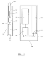
- Figure 1 shows a primary device 100 and a secondary device 102.
- the primary device 100 in this example is a charging unit for an electrically heated smoking system.
- the secondary device 102 in this example is an electrically heated aerosol-generating device adapted to receive a smoking article 104 comprising an aerosol-forming substrate.
- the secondary device includes a heater to heat the aerosol forming substrate in operation. The user inhales on a mouthpiece portion of the smoking article 104 to draw aerosol into the user's mouth.
- the secondary device 102 is configured to be received within a cavity 112 in the primary device 100 in order to recharge the power supply in the secondary device.
- the primary device 100 comprises first battery 106, control electronics 108, and electrical contacts 110 configured to provide electrical power to a second battery in the secondary device, from the first battery 106, when the secondary device is in connection with the electrical contacts 110.
- the electrical contacts 110 are provided adjacent the bottom of a cavity 112. The cavity is configured to receive the secondary device 102.
- the components of the primary device 100 are housed within the housing 116.
- the secondary device 102 comprises a second battery 126, secondary control electronics 128 and electrical contacts 130.
- the second, rechargeable battery 126 of the secondary device 102 is configured to receive a supply of power from the first battery 106 when the electrical contacts 130 are in contact with the electrical contacts 110 of the primary device 100.
- the secondary device 102 further comprises a cavity 132 configured to receive the smoking article 104.
- a heater 134 in the form of, for example, a blade heater, is provided at the bottom of the cavity 132. In use, the user activates the secondary device 102, and power is provided from the battery 126 via the control electronics 128 to the heater 134.
- the heater is heated to a standard operational temperature that is sufficient to generate an aerosol from the aerosol-forming substrate of the aerosol-generating article 104.
- the components of the secondary device 102 are housed within the housing 136.
- a secondary device of this type is described more fully in EP2110033 for example.
- the aerosol-forming substrate preferably comprises a tobacco-containing material containing volatile tobacco flavour compounds which are released from the substrate upon heating.
- the aerosol-forming substrate may comprise a non-tobacco material.
- the aerosol-forming substrate further comprises an aerosol former. Examples of suitable aerosol formers are glycerine and propylene glycol.
- the aerosol-forming substrate may be a solid substrate.
- the solid substrate may comprise, for example, one or more of: powder, granules, pellets, shreds, spaghettis, strips or sheets containing one or more of: herb leaf, tobacco leaf, fragments of tobacco ribs, reconstituted tobacco, homogenised tobacco, extruded tobacco and expanded tobacco.
- the aerosol-forming substrate may be a liquid substrate and the smoking article may comprise means for retaining the liquid substrate.
- the aerosol-forming substrate may alternatively be any other sort of substrate, for example, a gas substrate, or any combination of the various types of substrate.
- the secondary device 102 is an electrically heated smoking device.
- the secondary device 102 is small (conventional cigarette size) but must deliver high power over a period of just a few minutes, typically around 7 minutes for a single smoking session.
- the second battery may then need to be returned to the primary device 100 for recharging. Recharging is desirably completed, at least to a level sufficient to allow for another complete smoking experience, in a matter of a few minutes and preferably less than 6 minutes.
- the first battery 106 in the primary device is configured to hold sufficient charge to recharge the second battery 126 several times before needing recharging itself. This provides the user with a portable system that allows for several smoking sessions before recharging from a mains outlet is required.
- the second battery need not be frequently replaced.
- the second battery has a useful life of at least one year, equating to around 8000 charge/discharge cycles for a typical user.
- a lithium iron phosphate (LiFePO4) battery chemistry may be used, as in this example.
- the second battery 126 in this example has a cylindrical shape, with a diameter of 10mm and a length of 37mm. This battery is able to undergo 8000 cycles of charge/discharge at more than 900J per cycle.
- the average charging rate may be up to 12C.
- a charging rate of 1C means that the battery is fully charged from zero charge to full charge in one hour and a charging rate of 2C means that the battery is fully charged from zero charge to full charge in half an hour.
- the battery capacity is in the region of 125mAh.
- the maximum charging current can range from 980mA to 1.5A.
- Discharging is performed using 1millisecond pulses of up to 2A.
- Discharge rate depends on the resistance of the heater, which is in turn dependent of the heater temperature. At ambient temperature the discharge rate may be as high as 28C but is reduced at higher temperatures as the resistance of the heater increases. At typical operating temperature the discharging rate is around 13C.
- a lithium titanate battery may be used for the second battery.
- the first battery 106 in the primary unit 100 is a lithium cobalt oxide (LiCoO2) battery of the prismatic type.
- the first battery has a capacity of around 1350mAh, over ten times the capacity of the second battery.
- the second battery may be charged from the first battery at a rate between 2C and 16C. Discharging the first battery at a rate of 1C provides a charging rate of over 10C to the second battery. Charging of the first battery can be performed from a mains supply, at a rate between 0 and 1.5C, and typically at a rate of around 0.5C to maximise battery life.
- a lithium cobalt oxide battery provides a higher battery voltage than lithium iron phosphate, allowing the charging of a lithium iron phosphate battery from a single lithium cobalt oxide battery.
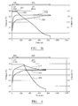
- Figure 2a shows a standard charging profile for charging a rechargeable battery.
- Figure 2a shows the charging voltage from the charging device 210, the charging current 220 from the charging device and the battery voltage 230 of the second battery being charged.
- the charging profile consists of an initial constant current phase 300.
- the charging voltage 210 is controlled so as to provide constant, maximum charging current I ch . This provides for the maximum rate of charging.
- the constant charging current phase 200 comes to an end when the charging voltage required to maintain the maximum charging current exceeds a maximum charging voltage V ch .
- V ch is set at a level that preserves the lifetime of the second battery.
- the charging voltage 210 is held at the maximum V ch .
- the charging current drops as the difference between the charging voltage 210 and battery voltage 230 drops.
- the charging process is stopped when the charging current reaches a low threshold I end .
- the maximum charging current and the maximum charging voltage are set by the battery manufacturer.
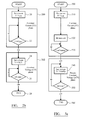
- FIG. 2b illustrates the control steps in this process.
- step 20 the charging current is set at I ch , the maximum charging current.
- the control logic compares the charging voltage with the maximum permitted charging voltage V ch . This is shown as step 22. If the charging voltage is below V ch the charging current is maintained. If the charging current is equal to or exceeds V ch , the constant current phase is ended and the charging voltage set to V ch . This is shown as step 24. The control logic then monitors the charging current in step 26. Once the charging current is less than I end the charging process is considered complete and is ended in step 28.
- the charging profile illustrated in Figures 2a and 2b can be used in a system as described with reference to Figure 1 .
- the charge time can be made shorter by compensating for the internal resistance in the charging circuit.
- a shorter charge time is desirable, particularly for systems such as electronic smoking systems, in which recharge time must be only a few minutes.
- FIG. 3 is a circuit diagram illustrating the charging circuit formed by the coupled primary and secondary devices.
- the circuit is divided in a primary device side and a secondary device side.
- Dotted line 30 represents the boundary between the primary device 100 and the secondary device 102.
- the primary device side comprises a controlled voltage source 320, comprising the first battery and a voltage regulator and a microcontroller 340 configured to control the voltage source 340 based on current I and voltage V measurements.
- the secondary device side comprises the second battery 126.
- the internal resistance of the charging circuit comprises contributions from several sources.
- the resistances r p- and r p+ represent the electrical resistances of the electronics layout and solder tabs in the primary device.
- the resistances r s- and r s+ represent the electrical resistances of the electronics layout and solder tabs in the primary device.
- the resistances r c- (t) and r c+ (t) represent the electrical resistances of the contacts between the primary and secondary devices. They will vary from device to device and can vary with time from charge cycle to charge cycle. In an electrical smoking system of the type described with reference to Figure 1 , primary and secondary units may be brought in and out of contact several times a day, and each time the contact resistances may be different. The contact resistances may also increase if the contacts are not kept clean.
- the resistance r i (t) represents the internal resistance of the second battery, which increases over the life of the second battery.
- the charging voltage supplied by the voltage source can be increased above the maximum V ch by an amount I * R(t) and the voltage across the second battery will be equal to V ch .
- the constant current phase of the charging profile can be extended until the point that the charging voltage reaches V ch + I * R(t).
- the charging voltage supplied thereafter can also be controlled to be more then V ch but no more than V ch + I * R(t).
- FIG. 4 illustrates a charging profile in accordance with an aspect of the invention, in which the supplied charging voltage exceeds V ch .
- the charging profile comprises a constant current phase 400 and a pseudo-constant voltage phase 402.
- the charging voltage from the voltage source is shown as 410
- the charging current is shown as 420
- the voltage of the second battery is shown as 430.
- the charging voltage is controlled to equal V comp .
- the charging cycle is ended when the charging current equals I end .
- FIG. 5a , 5b, and 5c illustrate alternative control strategies for implementing a charging profile as shown in Figure 4 .
- Figure 5a shows the process starting at step 500.
- the charging current is set to I ch the maximum charging current specified by the manufacturer.
- the internal resistance of the charging circuit is measured.
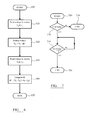
- the process for measuring the internal resistance of the charging circuit is shown in Figure 6 .
- a first step 610 the charging current I 1 and charging voltage V 1 are measured.
- ⁇ V is a fixed, predetermined voltage difference of a few millivolts.
- the reduced voltage V 2 and corresponding reduced current I 2 are measured in step 630.
- the voltage is only reduced for a period of 100-400 ⁇ s, long enough for the voltage and current to be measured once (or a few times to provide an average) by the microcontroller.
- the process ends at step 650, and may be repeated as described below.
- step 530 the charging voltage is compared with the compensated maximum charging voltage V comp .
- the internal resistance R i comprises both the parasitic resistance R(t) and the internal resistance of the battery r i (t).
- V comp V ch +R(t).
- the maximum internal resistance of the second battery r imax is provided by the battery manufacturer and can be used to derive a value for R(t) from R i .
- the voltage across the battery can be directly measured and passed to the microcontroller to allow the parasitic resistance to be determined. Using the value of R(t), V comp can be calculated.
- step 530 is repeated based on the calculated value of V comp . If the charging voltage is equal to or exceeds V comp then the constant current phase ends and the charging voltage is set to V comp in step 540. In step 550 the charging current is compared to I end . If the charging current is greater than or equal to I end , then the process returns to step 540. The charging voltage is reset to a new value of V comp based on the newly measured charging current and then the process proceeds to step 550. This control loop of step 540 and 550 can be repeated as frequently as desired. If in step 550 the charging current is less than I end then the charging cycle is terminated at step 560 and this is indicated to the user. The value of I end may be set based on the full capacity of the battery or may be based on the amount of energy required for one standard use of the secondary device, e.g. a single smoking session.
- FIG. 5b illustrates an alternative charging process.
- steps 500 and 510 are identical to those described with reference to Figure 5a .
- Step 515 is additional to the process shown in Figure 5a .
- the charging voltage is compared with V ch , the maximum charging voltage specified by the battery manufacturer. Only if the charging voltage is equal to or exceeds V ch does the process proceed to step 520, determination of the internal resistance.
- Steps 520 and 530 are as described with reference to Figure 5a , but in the process of Figure 5b , the internal resistance and V comp are only calculated after the charging voltage reaches V ch .
- the first step is a recalculation of the internal resistance, in step 535.
- the internal resistance of the charging circuit may have increased during the charging process, and recalculating allows for a better calculation of V comp and a potentially shorter charge time.
- Steps 540, 550 and 560 are as described with reference to Figure 5a .
- FIG. 5c illustrates a further alternative charging process.
- steps 500, 510 and 520 are as described with reference to Figure 5a .
- step 525 the charging voltage is compared with the compensated maximum charging voltage V comp , in the same manner as in step 530 in Figure 5a and 5b .
- step 525 if the charging voltage is greater than or equal to V comp the process returns to step 520.
- Steps 535 and 540 of Figure 5c are identical to steps 535 and 540 of Figure 5b .
- step 545 the charging current is compared to I end . If the charging current is greater than or equal to I end then the process return to step 535, and the internal resistance is recalculated and V comp updated prior to step 540. If in step 550 the charging current is less than I end then the charging cycle is terminated at step 560 and this is indicated to the user.
- the value of I end may be based on the full capacity of the battery so that the battery is charged to a certain proportion of full charge, say 90% of full charge. Alternatively I end may be set based on the amount of stored energy required for a single use of the secondary device.
- Figures 5a , 5b and 5c are example control processes and it should be clear that other processes are possible in accordance with the same general principle.
- any of the constant current phases of Figures 5a , 5b and 5c can be used with any of the pseudo-constant voltage phases of Figures 5a , 5b and 5c , providing nine different possible control processes.
- any decrease in the time taken to recharge the secondary device may significantly increase user adoption.
- a key requirement is ease and convenience of use, and in a recharge cycle lasting just a few minutes every second is noticeable.
- the recharging processes described with reference to Figure 4 and Figures 5a , 5b and 5c provide for rapid recharging within the limits of operation specified by the battery manufacturer.
- the secondary device 102 may be configured to prevent operation if the second battery drops below 20% of its fully charged level. This protects the life of the second battery.
- the control electronics 128 are configured to monitor the battery voltage of the second battery in use. When the battery voltage drops to 20% of the fully charged voltage, the device is disabled until the second battery has been recharged to a threshold charge level.
- the threshold charge level may be chosen to be less that maximum battery capacity, say 90% of full capacity, again to protect the life of the battery.
- the 20% level has been found to be a good threshold level for lithium iron phosphate batteries, but any level between 15% and 25% may be used and other levels may be chosen to suit different battery chemistries.
- FIG. 7 illustrates the control process that the control electronics 128 is configured to execute.
- the process starts in step 700.
- step 720 the battery voltage of the secondary battery is compared with a minimum starting voltage V min for allowing operation of the device. If the battery voltage is less than V min then the secondary device will not allow further operation of the heater and will enter a low power mode to conserve battery capacity until the next recharge cycle.
- the process then ends in step 730. In the case of a smoking device this prevents the heating operation of the device if there is insufficient charge in the second battery to complete a single smoking experience. Once the second battery has been recharged the process can restart at step 700.
- step 740 If the battery voltage is greater than or equal to V min then the device is allowed to fully operate. During operation, the battery voltage of the second battery is repeatedly compared to a second threshold, in this case V min /5, i.e. 20% of the minimum starting battery voltage. This is shown as step 740. If the battery voltage is greater than V min /5 then the device continues to be operable and step 740 is repeated. If the battery voltage is less than or equal to V min /5 then the device enters the low power mode in which the heater is disabled in step 750. Once the heater is disabled, the control process must start again at step 700 so the heater cannot operate until the second battery is recharged to a level at which that the battery voltage is greater than or equal to V min .
- V min /5 i.e. 20% of the minimum starting battery voltage.
Landscapes
- Engineering & Computer Science (AREA)
- Power Engineering (AREA)
- Computer Networks & Wireless Communication (AREA)
- Signal Processing (AREA)
- Chemical & Material Sciences (AREA)
- Chemical Kinetics & Catalysis (AREA)
- Electrochemistry (AREA)
- General Chemical & Material Sciences (AREA)
- Charge And Discharge Circuits For Batteries Or The Like (AREA)
- Secondary Cells (AREA)
- Hybrid Cells (AREA)
- Tests Of Electric Status Of Batteries (AREA)
Abstract
In one aspect, there is provided a charging device for rapidly charging a secondary battery, the charging device comprising: a pair of output terminals for connection to the secondary battery; a DC power source; a voltage regulator connected between the DC power source and to the output terminals for controlling a charging voltage; and a microprocessor coupled to the voltage regulator and to the output terminals, wherein the charging device and secondary battery are configured to be coupled together and to form a charging circuit, and wherein the microprocessor is configured to: control the voltage regulator to supply a first charging voltage; determine an internal resistance of the charging circuit by measuring the current in the charging circuit at the first charging voltage and at a second charging voltage, wherein the second charging voltage is lower than the first charging voltage; and limit the first charging voltage supplied by the voltage regulator to a level that compensates for the determined internal resistance.
Description
- The present invention relates to a portable electronic system including a charger and a secondary device, and to methods for charging and operation of the secondary device. The invention may be applied to portable electronic smoking systems.
- Electrically operated smoking systems of the prior art typically include a housing for receiving a smoking article, heating elements to generate an aerosol, a power source and electronic circuitry to control operation of the system.
- Portable electronic smoking devices need to be small and convenient for the user if they are to be widely adopted by smokers of conventional cigarettes. This leads to several technical requirements for the power source of a portable electronic smoking device. The power source, typically a battery, must be small enough to fit within a smoking device of similar size to a conventional cigarette and must deliver sufficient power to generate an aerosol from a smoking article. The idea of using a rechargeable battery has been suggested in the prior art, but in any commercially viable system the rechargeable battery must be able to deliver enough power for at least one smoking session, must be able to be quickly, safely and conveniently recharged to a level at which it can be reused for another smoking session, and must be operable for thousands of charge cycles.
- It is an object of the present invention to provide a system and charging method that meet these requirements for a rechargeable power source.
- One aspect of the disclosure provides a charging device for charging a secondary battery, the charging device comprising:
- a pair of output terminals for connection to the secondary battery, a DC power source, a voltage regulator connected between the DC power source and to the output terminals for controlling a charging voltage, and a microprocessor coupled to the voltage regulator and to the output terminals, wherein the charging device and secondary battery are configured to be coupled together and to form a charging circuit, and wherein the microprocessor is configured to:
- control the voltage regulator to supply a first charging voltage;
- determine an internal resistance of the charging circuit by measuring the current in the charging circuit at the first charging voltage and at a second charging voltage, wherein the second charging voltage is lower than the first charging voltage; and
- limit the first charging voltage supplied by the voltage regulator to a level that compensates for the determined internal resistance.
- With an ideal charging system, the charging profile is split into two parts: a constant current phase and a constant voltage phase. In the constant current phase, the voltage across the secondary battery is adjusted to maintain a constant maximum charging current Ich until the voltage across the battery reaches a defined voltage limit Vch, with Ich and Vch set by the properties of the battery. In the constant voltage phase the voltage across the battery is maintained at a fixed value Vch until the current drops below a predetermined value Ilow. For rapid charging it is desirable to maximise the length of the constant current phase.
- In practice the charging system is never ideal. The charging circuit formed by the charging device and the secondary battery has an internal resistance both as a result of the components of the charging circuit and the contact resistance between the charging device and the secondary battery. A proportion of the charging voltage supplied by the charging device will be dropped across the internal resistance of the charging circuit, so that the voltage across the secondary battery is less than the charging voltage supplied by the charging device. The charging device of the first aspect of the disclosure can provide a charging voltage greater than Vch. By determining the internal resistance of the charging circuit, the amount by which the charging voltage can exceed Vch so that the voltage across the battery is equal to or just less than Vch can be calculated. In this way the charging device supplies a charging voltage that compensates for the voltage drop across the internal resistance of the charging circuit. This increases the duration of the constant current charging phase because determining the cut off voltage Vch at the battery rather than at the voltage regulator means the cut off voltage is reached later.
- The internal resistance of the charging circuit changes over time. The internal resistance of the battery increases with the life of the battery. The contact resistance between the charging device and the secondary battery may also change over time and will vary from charger to charger and battery to battery. The charging device of the first aspect of the disclosure is configured to determine the internal resistance of the charging circuit during every charging cycle to ensure that the length of the constant current portion of the charging cycle is maximised.
- During a constant voltage phase, the microprocessor may be configured to limit the charging voltage supplied by the voltage regulator so that a voltage received by the secondary battery is equal to a predetermined maximum voltage, Vch.
- The second charging voltage is preferably non-zero and may have a predetermined voltage difference from the first charging voltage. Alternatively, the second charging voltage may be a predetermined non-zero voltage. With the second charging voltage non-zero, there is never any interruption to the charging process, which would lengthen the charge time.
- The microprocessor may be configured to adjust the first charging voltage to maintain a constant charging current in the charging circuit until the charging voltage exceeds a maximum charging voltage, the maximum charging voltage calculated based on the characteristics of the secondary battery and the determined internal resistance of the charging circuit.
- The microprocessor may be configured to calculate the maximum voltage and adjust the first charging voltage to maintain it at a level at or below the maximum charging voltage a plurality of times during a single charging cycle. Rather than simply supplying a constant charging voltage during a constant voltage phase, it is advantageous to provide an adjusted charging voltage that compensates for the voltage dropped across the internal resistance of the charging circuit. As the secondary battery approaches a fully charged level, the charging current for a given charging voltage falls. As a result, the voltage dropped across the internal resistance of the charging circuit falls. This in turn means that the charging voltage required to be supplied by the voltage regulator to ensure that the voltage across the battery is equal to Vch falls. It is therefore advantageous to recalculate the maximum charging voltage a plurality of times during a charging cycle, particularly as the charging current is falling. Accordingly, the microprocessor may be configured to continuously or periodically recalculate the maximum voltage and adjust the first charging voltage to maintain it at a level at or below the maximum charging voltage after the first charging voltage first reaches the maximum charging voltage during a single charging cycle.
- The microprocessor may be configured to determine the internal resistance and calculate the maximum charging voltage only after the first charging voltage has reached a predetermined voltage level. For example, the predetermined voltage level may be Vch, the maximum battery voltage.
- According to a second aspect of the disclosure, there is provided a method of charging a secondary battery comprising:
- connecting the secondary battery to a charging device having an adjustable voltage source to form a charging circuit;
- controlling a first voltage supplied by the voltage source to provide a predetermined charging current to the secondary battery;
- determining an internal resistance of the charging circuit by measuring the current in the charging circuit at the first charging voltage and at a second charging voltage, wherein the second charging voltage is lower than the first charging voltage;
- calculating a maximum charging voltage based on the determined internal resistance and a characteristic of the secondary battery; and
- adjusting the first charging voltage to maintain a predetermined charging current until the first charging voltage reaches the maximum voltage level, and thereafter adjusting the first charging voltage to maintain it at a level at or below the maximum charging voltage.
- As in the first aspect, the second charging voltage is preferably non-zero and may have a predetermined voltage difference from the first charging voltage.
- The steps of calculating the maximum voltage and adjusting the first charging voltage to maintain it at a level at or below the maximum charging voltage may be carried out a plurality of times during a single charging cycle.
- The steps of calculating the maximum voltage and adjusting the first charging voltage to maintain it at a level at or below the maximum charging voltage may be carried out continuously after the first charging voltage first reaches the maximum charging voltage during a single charging cycle.
- The step of determining the internal resistance may be carried out periodically during a charging cycle.
- The steps of determining the internal resistance and calculating the maximum charging voltage may be carried only after the first charging voltage has reached a predetermined voltage level. For example, the predetermined voltage level may be Vch, the maximum battery voltage.
- In a third aspect of the disclosure, there is provided a charging device comprising:
- a pair of output terminals for connection to a secondary battery;
- a DC power source;
- a voltage regulator connected between the DC power source and to the output terminals for controlling a charging voltage; and
- a microprocessor coupled to the voltage regulator and to the output terminals, wherein the charging device and secondary battery are configured to be coupled together and to form a charging circuit, and wherein the microprocessor is configured to:
- control the voltage regulator to supply a first charging voltage;
- determine an internal resistance of the charging circuit;
- calculate a maximum charging voltage based on the determined internal resistance and a characteristic of the secondary battery;
- adjust the first charging voltage to maintain a predetermined charging current until the first charging voltage reaches the maximum charging voltage, thereafter adjust the first charging voltage to a level at or below the maximum charging voltage, and thereafter periodically or continuously recalculate the maximum charging voltage and adjust the charging voltage to maintain it at a level at or below the recalculated maximum charging voltage.
- Rather than simply supplying a constant charging voltage during a constant voltage phase, it is advantageous to provide an adjusted charging voltage that compensates for the voltage dropped across the internal resistance of the charging circuit. As the secondary battery approaches a fully charged level, the charging current falls for a given charging voltage. As a result, the voltage dropped across the internal resistance of the charging circuit falls. This in turn means that the charging voltage required to be supplied by the voltage regulator to ensure that the voltage across the battery is equal to Vch falls. It is therefore advantageous to recalculate the maximum charging voltage a plurality of times during a charging cycle, particularly as the charging current is falling. Accordingly, the microprocessor is configured to continuously or periodically recalculate the maximum voltage and adjust the first charging voltage to maintain it at a level at or below the maximum charging voltage after the first charging voltage first reaches the maximum charging voltage. The step of determining the internal resistance may comprise measuring the internal resistance or estimating the internal resistance.
- In a fourth aspect of the disclosure, there is provided a method of charging a secondary battery comprising:
- connecting the secondary battery to a charging device having an adjustable voltage source to form a charging circuit;
- controlling a first voltage supplied by the voltage source to provide a predetermined charging current to the secondary battery;
- determining an internal resistance of the charging circuit;
- calculating a maximum charging voltage based on the determined internal resistance and a characteristic of the secondary battery;
- adjusting the first charging voltage to maintain a predetermined charging current until the first charging voltage reaches the maximum charging voltage, thereafter adjusting the first charging voltage to a level at or below the maximum charging voltage; and thereafter periodically or continuously recalculating the maximum charging voltage and adjusting the charging voltage to maintain it at a level at or below the recalculated maximum charging voltage.
- The charging device and method in accordance with the first, second, third and fourth aspects of the disclosure may be applied to electronic smoking systems. The charging device may be used to charge a secondary battery in an electronic smoking device. The electronic smoking device may include an electrically powered heater configured to heat an aerosol-forming substrate. The aerosol-forming substrate may be provided in the form of a cigarette having a mouthpiece portion on which an end user inhales. The secondary battery may advantageously provide sufficient power for a single smoking session, exhausting a single aerosol-forming substrate.
- A short recharging time is crucial for the acceptance of electronic cigarettes. The charging device and charging method of the present disclosure maximise the duration of a constant current phase of the recharging process and also maximise the voltage across the secondary battery when the constant current phase has ended.
- In a fifth aspect of the invention, there is provided a portable electrical system comprising primary and secondary devices, the primary device having a first, lithium cobalt oxide battery and the secondary device having a second, lithium iron phosphate or lithium titanate battery, wherein the primary and secondary devices are configured to allow recharging of the second battery from the first battery.
- The secondary device may be an electrically heated smoking device. The electrically heated smoking device may comprise an electrical heater powered by the second battery. The electrical heater may be configured to heat an aerosol-forming substrate. The primary device may be a portable charging unit, and may be made a shape and size similar to a conventional pack of cigarettes. The secondary device may be received within the secondary device during a recharging cycle.
- The use of a lithium iron phosphate (or lithium titanate) battery for the secondary device safely allows for fast charge and discharge rates. In the case of an electrically heated smoking device, fast discharge is required because high power is required to be delivered to the heater over a time period of only a few minutes. Fast charge is required because smokers often wish to smoke another cigarette very shortly after a first cigarette.
- To provide charging of the second battery from a single first battery, the first battery must have a higher voltage than the second battery. The first battery must also have greater charge capacity than the second battery if it is to provide for multiple recharge cycles before needing recharging or replacing itself. A lithium cobalt oxide battery chemistry provides for a greater battery voltage, and a greater charge capacity for a given size, than a lithium iron phosphate (or lithium titanate) battery. The combination of a primary device having a first, lithium cobalt oxide battery and a secondary device having a second, lithium iron phosphate or lithium titanate battery is therefore advantageous for a portable electrical smoking system, or any similar portable system in which a secondary device requires a short burst of high power from a battery.
- The capacity of the first battery may advantageously be at least five times greater than the capacity of the second battery. The capacity of the first battery may advantageously be between five and forty times the capacity of the second battery.
- In a sixth aspect of the disclosure, there is provided an electrically heated smoking system comprising:
- a lithium iron phosphate or lithium titanate battery;
- a heater element, wherein operation of the heater element discharges the battery; and
- a discharge detection circuit connected to the battery, wherein system is configured to disable operation of the heater element when the discharge detection circuits determines that the battery voltage is less than a threshold voltage level.
- The threshold voltage level may be set to a voltage above a voltage below which battery capacity is irrecoverably reduced. For example, the battery may have a maximum battery voltage and the threshold voltage level may be between 15% and 25% of the maximum battery voltage. Below this level of charge battery capacity may be irrecoverably lost. However, improvements or changes in battery chemistry may allow the threshold level to be reduced to below 15%, for example to 5% of maximum battery voltage.
- Ensuring that the battery does not fully discharge substantially reduces irreversible reactions in the battery, and thereby preserves the operational life of the battery.
- It should be clear that features described in relation to one aspect of the disclosure may be applied to other aspects of the disclosure, alone or in combination with other described aspects and features of the disclosure.
- Examples in accordance with the various aspects of the disclosure will now be described in detail, with reference to accompanying drawings, in which:
-
Figure 1 is a schematic diagram showing an example of an electronic smoking system comprising primary and secondary units; -
Figure 2a shows a standard charging profile for a rechargeable battery in accordance with the prior art; -
Figure 2b is a flow diagram illustrating a control process for the charging profile ofFigure 2a ; -
Figure 3 is a schematic illustration of a charging circuit formed by the coupled primary and secondary devices ofFigure 1 ; -
Figure 4 shows a charging profile in accordance with an embodiment of the invention; -
Figure 5a is a flow diagram illustrating a control process for the charging profile ofFigure 4 ; -
Figure 5b is a flow diagram illustrating an alternative control process for the charging profile ofFigure 4 ; -
Figure 5c is a flow diagram illustrating a further alternative control process for the charging profile ofFigure 4 ; -
Figure 6 is a flow diagram illustrating a process for calculating an internal resistance of the charging circuit; and -
Figure 7 is flow diagram illustrating a control process for preventing excessive discharge of the secondary battery in a system of the type shown inFigure 1 . -
Figure 1 shows aprimary device 100 and asecondary device 102. Theprimary device 100 in this example is a charging unit for an electrically heated smoking system. Thesecondary device 102 in this example is an electrically heated aerosol-generating device adapted to receive asmoking article 104 comprising an aerosol-forming substrate. The secondary device includes a heater to heat the aerosol forming substrate in operation. The user inhales on a mouthpiece portion of thesmoking article 104 to draw aerosol into the user's mouth. Thesecondary device 102 is configured to be received within acavity 112 in theprimary device 100 in order to recharge the power supply in the secondary device. - The
primary device 100 comprisesfirst battery 106,control electronics 108, andelectrical contacts 110 configured to provide electrical power to a second battery in the secondary device, from thefirst battery 106, when the secondary device is in connection with theelectrical contacts 110. Theelectrical contacts 110 are provided adjacent the bottom of acavity 112. The cavity is configured to receive thesecondary device 102. The components of theprimary device 100 are housed within thehousing 116. - The
secondary device 102 comprises asecond battery 126,secondary control electronics 128 andelectrical contacts 130. As described above, the second,rechargeable battery 126 of thesecondary device 102 is configured to receive a supply of power from thefirst battery 106 when theelectrical contacts 130 are in contact with theelectrical contacts 110 of theprimary device 100. Thesecondary device 102 further comprises acavity 132 configured to receive thesmoking article 104. Aheater 134, in the form of, for example, a blade heater, is provided at the bottom of thecavity 132. In use, the user activates thesecondary device 102, and power is provided from thebattery 126 via thecontrol electronics 128 to theheater 134. The heater is heated to a standard operational temperature that is sufficient to generate an aerosol from the aerosol-forming substrate of the aerosol-generatingarticle 104. The components of thesecondary device 102 are housed within thehousing 136. A secondary device of this type is described more fully inEP2110033 for example. - The aerosol-forming substrate preferably comprises a tobacco-containing material containing volatile tobacco flavour compounds which are released from the substrate upon heating. Alternatively, the aerosol-forming substrate may comprise a non-tobacco material. Preferably, the aerosol-forming substrate further comprises an aerosol former. Examples of suitable aerosol formers are glycerine and propylene glycol.
- The aerosol-forming substrate may be a solid substrate. The solid substrate may comprise, for example, one or more of: powder, granules, pellets, shreds, spaghettis, strips or sheets containing one or more of: herb leaf, tobacco leaf, fragments of tobacco ribs, reconstituted tobacco, homogenised tobacco, extruded tobacco and expanded tobacco. Alternatively, the aerosol-forming substrate may be a liquid substrate and the smoking article may comprise means for retaining the liquid substrate. The aerosol-forming substrate may alternatively be any other sort of substrate, for example, a gas substrate, or any combination of the various types of substrate.
- In this example, the
secondary device 102 is an electrically heated smoking device. As such thesecondary device 102 is small (conventional cigarette size) but must deliver high power over a period of just a few minutes, typically around 7 minutes for a single smoking session. The second battery may then need to be returned to theprimary device 100 for recharging. Recharging is desirably completed, at least to a level sufficient to allow for another complete smoking experience, in a matter of a few minutes and preferably less than 6 minutes. - The
first battery 106 in the primary device is configured to hold sufficient charge to recharge thesecond battery 126 several times before needing recharging itself. This provides the user with a portable system that allows for several smoking sessions before recharging from a mains outlet is required. - It is also desirable that the second battery need not be frequently replaced. Preferably the second battery has a useful life of at least one year, equating to around 8000 charge/discharge cycles for a typical user.
- In order to satisfy the competing requirements for the
second battery 126 of small size, sufficient capacity and safe, but fast, charge and discharge, as well as acceptable lifetime, a lithium iron phosphate (LiFePO4) battery chemistry may be used, as in this example. Thesecond battery 126 in this example has a cylindrical shape, with a diameter of 10mm and a length of 37mm. This battery is able to undergo 8000 cycles of charge/discharge at more than 900J per cycle. The average charging rate may be up to 12C. A charging rate of 1C means that the battery is fully charged from zero charge to full charge in one hour and a charging rate of 2C means that the battery is fully charged from zero charge to full charge in half an hour. The battery capacity is in the region of 125mAh. The maximum charging current can range from 980mA to 1.5A. Discharging is performed using 1millisecond pulses of up to 2A. Discharge rate depends on the resistance of the heater, which is in turn dependent of the heater temperature. At ambient temperature the discharge rate may be as high as 28C but is reduced at higher temperatures as the resistance of the heater increases. At typical operating temperature the discharging rate is around 13C. As an alternative, a lithium titanate battery may be used for the second battery. - The
first battery 106 in theprimary unit 100 is a lithium cobalt oxide (LiCoO2) battery of the prismatic type. The first battery has a capacity of around 1350mAh, over ten times the capacity of the second battery. The second battery may be charged from the first battery at a rate between 2C and 16C. Discharging the first battery at a rate of 1C provides a charging rate of over 10C to the second battery. Charging of the first battery can be performed from a mains supply, at a rate between 0 and 1.5C, and typically at a rate of around 0.5C to maximise battery life. - A lithium cobalt oxide battery provides a higher battery voltage than lithium iron phosphate, allowing the charging of a lithium iron phosphate battery from a single lithium cobalt oxide battery.
-
Figure 2a shows a standard charging profile for charging a rechargeable battery.Figure 2a shows the charging voltage from the chargingdevice 210, the charging current 220 from the charging device and thebattery voltage 230 of the second battery being charged. The charging profile consists of an initial constant current phase 300. During the constant current phase 300 the chargingvoltage 210 is controlled so as to provide constant, maximum charging current Ich. This provides for the maximum rate of charging. However, the constant chargingcurrent phase 200 comes to an end when the charging voltage required to maintain the maximum charging current exceeds a maximum charging voltage Vch. Vch is set at a level that preserves the lifetime of the second battery. Once this stage is reached, indicated atpoint 203 onFigure 2a , aconstant voltage phase 202 begins. During the constant voltage phase the chargingvoltage 210 is held at the maximum Vch. During the constant voltage phase, the charging current drops as the difference between the chargingvoltage 210 andbattery voltage 230 drops. The charging process is stopped when the charging current reaches a low threshold Iend. The maximum charging current and the maximum charging voltage are set by the battery manufacturer. -
Figure 2b illustrates the control steps in this process. Instep 20 the charging current is set at Ich, the maximum charging current. During the constant current phase, the control logic compares the charging voltage with the maximum permitted charging voltage Vch. This is shown asstep 22. If the charging voltage is below Vch the charging current is maintained. If the charging current is equal to or exceeds Vch, the constant current phase is ended and the charging voltage set to Vch. This is shown asstep 24. The control logic then monitors the charging current instep 26. Once the charging current is less than Iend the charging process is considered complete and is ended instep 28. - The charging profile illustrated in
Figures 2a and2b can be used in a system as described with reference toFigure 1 . However, the charge time can be made shorter by compensating for the internal resistance in the charging circuit. A shorter charge time is desirable, particularly for systems such as electronic smoking systems, in which recharge time must be only a few minutes. -
Figure 3 is a circuit diagram illustrating the charging circuit formed by the coupled primary and secondary devices. The circuit is divided in a primary device side and a secondary device side.Dotted line 30 represents the boundary between theprimary device 100 and thesecondary device 102. The primary device side comprises a controlledvoltage source 320, comprising the first battery and a voltage regulator and amicrocontroller 340 configured to control thevoltage source 340 based on current I and voltage V measurements. The secondary device side comprises thesecond battery 126. The internal resistance of the charging circuit comprises contributions from several sources. The resistances rp- and rp+ represent the electrical resistances of the electronics layout and solder tabs in the primary device. The resistances rs- and rs+ represent the electrical resistances of the electronics layout and solder tabs in the primary device. The resistances rc-(t) and rc+(t) represent the electrical resistances of the contacts between the primary and secondary devices. They will vary from device to device and can vary with time from charge cycle to charge cycle. In an electrical smoking system of the type described with reference toFigure 1 , primary and secondary units may be brought in and out of contact several times a day, and each time the contact resistances may be different. The contact resistances may also increase if the contacts are not kept clean. The resistance ri(t) represents the internal resistance of the second battery, which increases over the life of the second battery. - If the parasitic resistances rp-, rp+, rs-, rs+, rc-(t) and rc+(t) are combined into a single resistance R(t), then the voltage across the second battery will be less than the charging voltage from the voltage source by Vdrop= I * R(t).
- This means that the charging voltage supplied by the voltage source can be increased above the maximum Vch by an amount I * R(t) and the voltage across the second battery will be equal to Vch. The constant current phase of the charging profile can be extended until the point that the charging voltage reaches Vch + I * R(t). The charging voltage supplied thereafter can also be controlled to be more then Vch but no more than Vch + I * R(t).
-
Figure 4 illustrates a charging profile in accordance with an aspect of the invention, in which the supplied charging voltage exceeds Vch. The charging profile comprises a constantcurrent phase 400 and apseudo-constant voltage phase 402. The charging voltage from the voltage source is shown as 410, the charging current is shown as 420 and the voltage of the second battery is shown as 430. - The constant
current phase 400 extends until the charging voltage reaches a maximum of Vcomp=Vch + I * R(t). In thepseudo-constant voltage phase 402, the charging voltage is controlled to equal Vcomp. The charging cycle is ended when the charging current equals Iend. -
Figure 5a ,5b, and 5c illustrate alternative control strategies for implementing a charging profile as shown inFigure 4 .Figure 5a shows the process starting atstep 500. Atstep 510 the charging current is set to Ich the maximum charging current specified by the manufacturer. Instep 520 the internal resistance of the charging circuit is measured. - The process for measuring the internal resistance of the charging circuit is shown in
Figure 6 . In afirst step 610 the charging current I1 and charging voltage V1 are measured. The charging voltage is then reduced to a lower voltage V2 instep 620, where V2=V1-ΔV. ΔV is a fixed, predetermined voltage difference of a few millivolts. The reduced voltage V2 and corresponding reduced current I2 are measured instep 630. The voltage is only reduced for a period of 100-400µs, long enough for the voltage and current to be measured once (or a few times to provide an average) by the microcontroller. The internal resistance Ri of the charging circuit is calculated instep 640 using the relationship Ri=(V1-V2)/(I1-I2). The process ends atstep 650, and may be repeated as described below. - In
step 530 the charging voltage is compared with the compensated maximum charging voltage Vcomp. The internal resistance Ri comprises both the parasitic resistance R(t) and the internal resistance of the battery ri(t). Vcomp=Vch+R(t). The maximum internal resistance of the second battery rimax is provided by the battery manufacturer and can be used to derive a value for R(t) from Ri. As an alternative, the voltage across the battery can be directly measured and passed to the microcontroller to allow the parasitic resistance to be determined. Using the value of R(t), Vcomp can be calculated. - If the charging voltage is less than Vcomp the constant current phase continues and step 530 is repeated based on the calculated value of Vcomp. If the charging voltage is equal to or exceeds Vcomp then the constant current phase ends and the charging voltage is set to Vcomp in
step 540. Instep 550 the charging current is compared to Iend. If the charging current is greater than or equal to Iend, then the process returns to step 540. The charging voltage is reset to a new value of Vcomp based on the newly measured charging current and then the process proceeds to step 550. This control loop ofstep step 550 the charging current is less than Iend then the charging cycle is terminated atstep 560 and this is indicated to the user. The value of Iend may be set based on the full capacity of the battery or may be based on the amount of energy required for one standard use of the secondary device, e.g. a single smoking session. -
Figure 5b illustrates an alternative charging process. In the process ofFigure 5b , steps 500 and 510 are identical to those described with reference toFigure 5a . Step 515 is additional to the process shown inFigure 5a . Instep 515 the charging voltage is compared with Vch, the maximum charging voltage specified by the battery manufacturer. Only if the charging voltage is equal to or exceeds Vch does the process proceed to step 520, determination of the internal resistance.Steps Figure 5a , but in the process ofFigure 5b , the internal resistance and Vcomp are only calculated after the charging voltage reaches Vch. In the pseudo-constant current phase ofFigure 5b , the first step is a recalculation of the internal resistance, instep 535. The internal resistance of the charging circuit may have increased during the charging process, and recalculating allows for a better calculation of Vcomp and a potentially shorter charge time.Steps Figure 5a . -
Figure 5c illustrates a further alternative charging process. In the process ofFigure 5c steps 500, 510 and 520 are as described with reference toFigure 5a . In step 525 the charging voltage is compared with the compensated maximum charging voltage Vcomp, in the same manner as instep 530 inFigure 5a and5b . However, in step 525, if the charging voltage is greater than or equal to Vcomp the process returns to step 520. -
Steps Figure 5c are identical tosteps Figure 5b . Instep 545 the charging current is compared to Iend. If the charging current is greater than or equal to Iend then the process return to step 535, and the internal resistance is recalculated and Vcomp updated prior to step 540. If instep 550 the charging current is less than Iend then the charging cycle is terminated atstep 560 and this is indicated to the user. As explained above, the value of Iend may be based on the full capacity of the battery so that the battery is charged to a certain proportion of full charge, say 90% of full charge. Alternatively Iend may be set based on the amount of stored energy required for a single use of the secondary device. -
Figures 5a ,5b and 5c are example control processes and it should be clear that other processes are possible in accordance with the same general principle. For example any of the constant current phases ofFigures 5a ,5b and 5c , can be used with any of the pseudo-constant voltage phases ofFigures 5a ,5b and 5c , providing nine different possible control processes. - In systems such as an electrical smoking system, any decrease in the time taken to recharge the secondary device may significantly increase user adoption. A key requirement is ease and convenience of use, and in a recharge cycle lasting just a few minutes every second is noticeable. The recharging processes described with reference to
Figure 4 andFigures 5a ,5b and 5c provide for rapid recharging within the limits of operation specified by the battery manufacturer. - A further aspect of this disclosure is illustrated in
Figure 7 . With reference to the secondary device shown inFigure 1 , thesecondary device 102 may be configured to prevent operation if the second battery drops below 20% of its fully charged level. This protects the life of the second battery. Thecontrol electronics 128 are configured to monitor the battery voltage of the second battery in use. When the battery voltage drops to 20% of the fully charged voltage, the device is disabled until the second battery has been recharged to a threshold charge level. The threshold charge level may be chosen to be less that maximum battery capacity, say 90% of full capacity, again to protect the life of the battery. The 20% level has been found to be a good threshold level for lithium iron phosphate batteries, but any level between 15% and 25% may be used and other levels may be chosen to suit different battery chemistries. -
Figure 7 illustrates the control process that thecontrol electronics 128 is configured to execute. The process starts instep 700. Instep 720 the battery voltage of the secondary battery is compared with a minimum starting voltage Vmin for allowing operation of the device. If the battery voltage is less than Vmin then the secondary device will not allow further operation of the heater and will enter a low power mode to conserve battery capacity until the next recharge cycle. The process then ends instep 730. In the case of a smoking device this prevents the heating operation of the device if there is insufficient charge in the second battery to complete a single smoking experience. Once the second battery has been recharged the process can restart atstep 700. - If the battery voltage is greater than or equal to Vmin then the device is allowed to fully operate. During operation, the battery voltage of the second battery is repeatedly compared to a second threshold, in this case Vmin/5, i.e. 20% of the minimum starting battery voltage. This is shown as
step 740. If the battery voltage is greater than Vmin/5 then the device continues to be operable and step 740 is repeated. If the battery voltage is less than or equal to Vmin/5 then the device enters the low power mode in which the heater is disabled instep 750. Once the heater is disabled, the control process must start again atstep 700 so the heater cannot operate until the second battery is recharged to a level at which that the battery voltage is greater than or equal to Vmin. - The exemplary embodiments described above illustrate but are not limiting. In view of the above discussed exemplary embodiments, other embodiments consistent with the above exemplary embodiments will now be apparent to one of ordinary skill in the art.
Claims (22)
- A charging device for charging a secondary battery, the charging device comprising:a pair of output terminals for connection to the secondary battery;a DC power source;a voltage regulator connected between the DC power source and to the output terminals for controlling a charging voltage; anda microprocessor coupled to the voltage regulator and to the output terminals, wherein the charging device and secondary battery are configured to be coupled together and to form a charging circuit, and wherein the microprocessor is configured to:control the voltage regulator to supply a first charging voltage;determine an internal resistance of the charging circuit by measuring the current in the charging circuit at the first charging voltage and at a second charging voltage, wherein the second charging voltage is lower than the first charging voltage; andlimit the first charging voltage supplied by the voltage regulator to a level that compensates for the determined internal resistance.
- A charging device according to claim 1, wherein the microprocessor is configured to limit the charging voltage supplied by the voltage regulator so that a voltage received by the secondary battery is equal to a predetermined maximum voltage.
- A charging device according to claim 1 or 2, wherein the second charging voltage has a predetermined voltage difference from the first charging voltage.
- A charging device according to any preceding claim, wherein the microprocessor is configured to adjust the first charging voltage to maintain a constant charging current in the charging circuit until the charging voltage exceeds a maximum charging voltage, the maximum charging voltage calculated based on the characteristics of the secondary battery and the determined internal resistance of the charging circuit.
- A charging device according to claim 4, wherein the microprocessor is configured to calculate the maximum charging voltage and adjust the first charging voltage to maintain it at a level at or below the maximum charging voltage a plurality of times during a single charging cycle.
- A charging device according to claim 4 or 5, wherein the microprocessor is configured to continuously recalculate the maximum charging voltage and adjust the first charging voltage to maintain it at a level at or below the maximum charging voltage after the first charging voltage first reaches the maximum charging voltage during a single charging cycle.
- A charging device according to claim 4, 5 or 6, wherein microprocessor is configured to determine the internal resistance and calculate the maximum charging voltage only after the first charging voltage has reached a predetermined voltage level.
- A charging device according to any preceding claim, wherein the microprocessor is configured to recalculate the internal resistance periodically.
- A method of charging a secondary battery comprising:connecting the secondary battery to a charging device having an adjustable voltage source to form a charging circuit;controlling a first voltage supplied by the voltage source to provide a predetermined charging current to the secondary battery;determining an internal resistance of the charging circuit by measuring the current in the charging circuit at the first charging voltage and at a second charging voltage, wherein the second charging voltage is lower than the first charging voltage;calculating a maximum charging voltage based on the determined internal resistance and a characteristic of the secondary battery; andadjusting the first charging voltage to maintain a predetermined charging current until the first charging voltage reaches the maximum voltage level, and thereafter adjusting the first charging voltage to maintain it at a level at or below the maximum charging voltage.
- A method according to claim 9, wherein the second voltage has a predetermined voltage difference from the first charging voltage.
- A method according to claim 9 or 10, wherein the steps of calculating the maximum voltage and adjusting the first charging voltage to maintain it at a level at or below the maximum charging voltage are carried out a plurality of times during a single charging cycle.
- A method according to claim 11, wherein the steps of calculating the maximum voltage and adjusting the first charging voltage to maintain it at a level at or below the maximum charging voltage are carried out continuously after the first charging voltage first reaches the maximum charging voltage during a single charging cycle.
- A method according to any one of claims 9 to 12, wherein the step of determining the internal resistance is carried out periodically.
- A method according to any one of claims 9 to 13, wherein the steps of determining the internal resistance and calculating the maximum charging voltage are carried only after the first charging voltage has reached a predetermined voltage level.
- A charging device comprising:a pair of output terminals for connection to a secondary battery;a DC power source;a voltage regulator connected between the DC power source and to the output terminals for controlling a charging voltage; anda microprocessor coupled to the voltage regulator and to the output terminals, wherein the charging device and secondary battery are configured to be coupled together and to form a charging circuit, and wherein the microprocessor is configured to:control the voltage regulator to supply a first charging voltage;determine an internal resistance of the charging circuit;calculate a maximum charging voltage based on the determined internal resistance and a characteristic of the secondary battery;adjust the first charging voltage to maintain a predetermined charging current until the first charging voltage reaches the maximum charging voltage, thereafter adjust the first charging voltage to a level at or below the maximum charging voltage, and thereafter periodically or continuously recalculate the maximum charging voltage and adjust the charging voltage to maintain it at a level at or below the recalculated maximum charging voltage.
- A method of charging a secondary battery comprising:connecting the secondary battery to a charging device having an adjustable voltage source to form a charging circuit;controlling a first voltage supplied by the voltage source to provide a predetermined charging current to the secondary battery;determining an internal resistance of the charging circuit;calculating a maximum charging voltage based on the determined internal resistance and a characteristic of the secondary battery;adjusting the first charging voltage to maintain a predetermined charging current until the first charging voltage reaches the maximum charging voltage, thereafter adjusting the first charging voltage to a level at or below the maximum charging voltage; and thereafter periodically or continuously recalculating the maximum charging voltage and adjusting the charging voltage to maintain it at a level at or below the recalculated maximum charging voltage.
- A portable electrical system comprising primary and secondary devices, the primary device having a first, lithium cobalt oxide battery and the secondary device having a second, lithium iron phosphate or lithium titanate battery, wherein the primary and secondary devices are configured to allow recharging of the second battery from the first battery.
- A portable electrical system according to claim 17, wherein the capacity of the first battery is at least five times greater than the capacity of the second battery.
- A portable electrical system according to claim 18, wherein the capacity of the first battery is between five and forty times the capacity of the second battery.
- A portable electrical system according to any one of claims 17 to 19, wherein the secondary device is an electrically heated smoking device.
- An electrically heated smoking system comprising:a lithium iron phosphate or lithium titanate battery;a heater element, wherein operation of the heater element discharges the battery; anda discharge detection circuit connected to the battery, wherein system is configured to disable operation of the heater element when the discharge detection circuits determined that the battery voltage is less than a threshold voltage level.
- An electrically heated smoking system according to claim 21, wherein the threshold voltage level is set to a voltage above a voltage below which battery capacity is irrecoverably reduced.
Priority Applications (35)
| Application Number | Priority Date | Filing Date | Title |
|---|---|---|---|
| EP20120181682 EP2701268A1 (en) | 2012-08-24 | 2012-08-24 | Portable electronic system including charging device and method of charging a secondary battery |
| JP2015527935A JP5958846B2 (en) | 2012-08-24 | 2013-08-23 | Portable electronic system including a charging device and method for charging a secondary battery |
| NZ705714A NZ705714A (en) | 2012-08-24 | 2013-08-23 | Portable electronic system including charging device and method of charging a secondary battery |
| SI201330763T SI2896104T1 (en) | 2012-08-24 | 2013-08-23 | Portable electronic system including charging device and method of charging a secondary battery |
| MX2015002436A MX339689B (en) | 2012-08-24 | 2013-08-23 | Portable electronic system including charging device and method of charging a secondary battery. |
| ES17175856T ES2886111T3 (en) | 2012-08-24 | 2013-08-23 | Portable electronics including a charging device and charging method for a secondary battery |
| ES13765660.9T ES2636592T3 (en) | 2012-08-24 | 2013-08-23 | Portable electronic system that includes a charging device and method for charging a secondary battery |
| PT137656609T PT2896104T (en) | 2012-08-24 | 2013-08-23 | Portable electronic system including charging device and method of charging a secondary battery |
| SG11201501313QA SG11201501313QA (en) | 2012-08-24 | 2013-08-23 | Portable electronic system including charging device and method of charging a secondary battery |
| UAA201502046A UA117564C2 (en) | 2012-08-24 | 2013-08-23 | Portable electronic system including charging device and method of charging a secondary battery |
| PCT/EP2013/067563 WO2014029880A2 (en) | 2012-08-24 | 2013-08-23 | Portable electronic system including charging device and method of charging a secondary battery |
| RS20170788A RS56372B1 (en) | 2012-08-24 | 2013-08-23 | Portable electronic system including charging device and method of charging a secondary battery |
| CN201710682891.7A CN107453430B (en) | 2012-08-24 | 2013-08-23 | Portable electronic system including charging device and method of charging secondary battery |
| HUE17175856A HUE055479T2 (en) | 2012-08-24 | 2013-08-23 | Portable electronic system including charging device and method of charging a secondary battery |
| EP13765660.9A EP2896104B1 (en) | 2012-08-24 | 2013-08-23 | Portable electronic system including charging device and method of charging a secondary battery |
| KR1020157004957A KR101619032B1 (en) | 2012-08-24 | 2013-08-23 | Portable electronic system including charging device and method of charging a secondary battery |
| DK13765660.9T DK2896104T3 (en) | 2012-08-24 | 2013-08-23 | Portable electronic system including charging device and method for charging a secondary battery |
| RU2015110242A RU2609131C2 (en) | 2012-08-24 | 2013-08-23 | Portable electronic system, including charging device, and secondary battery charging method |
| CA2882470A CA2882470C (en) | 2012-08-24 | 2013-08-23 | Portable electronic system including charging device and method of charging a secondary battery |
| AU2013304892A AU2013304892B2 (en) | 2012-08-24 | 2013-08-23 | Portable electronic system including charging device and method of charging a secondary battery |
| BR112015003580-9A BR112015003580B1 (en) | 2012-08-24 | 2013-08-23 | PORTABLE ELECTRONIC SYSTEM INCLUDING CHARGING DEVICE AND METHOD OF CHARGING A SECONDARY BATTERY |
| PL17175856T PL3285354T3 (en) | 2012-08-24 | 2013-08-23 | Portable electronic system including charging device and method of charging a secondary battery |
| PL13765660T PL2896104T3 (en) | 2012-08-24 | 2013-08-23 | Portable electronic system including charging device and method of charging a secondary battery |
| US14/423,604 US9655383B2 (en) | 2012-08-24 | 2013-08-23 | Portable electronic system including charging device and method of charging a secondary battery |
| EP17175856.8A EP3285354B1 (en) | 2012-08-24 | 2013-08-23 | Portable electronic system including charging device and method of charging a secondary battery |
| CN201380044030.6A CN104584366B (en) | 2012-08-24 | 2013-08-23 | Portable electronic system including charging equipment and the method to secondary cell charging |
| LTEP13765660.9T LT2896104T (en) | 2012-08-24 | 2013-08-23 | Portable electronic system including charging device and method of charging a secondary battery |
| HUE13765660A HUE033539T2 (en) | 2012-08-24 | 2013-08-23 | Portable electronic system including charging device and method of charging a secondary battery |
| MYPI2015700514A MY169199A (en) | 2012-08-24 | 2013-08-23 | Portable electronic system including charging device and method of charging a secondary battery |
| IL237108A IL237108B (en) | 2012-08-24 | 2015-02-05 | Portable electronic smoking system including charging device and method of charging a secondary battery |
| ZA2015/00951A ZA201500951B (en) | 2012-08-24 | 2015-02-09 | Portable electronic system including charging device and method of charging a secondary battery |
| PH12015500272A PH12015500272B1 (en) | 2012-08-24 | 2015-02-09 | Portable electronic system including charging device and method of charging a secondary battery |
| IN1214DEN2015 IN2015DN01214A (en) | 2012-08-24 | 2015-02-14 | |
| HK15109658.7A HK1208964A1 (en) | 2012-08-24 | 2015-09-30 | Portable electronic system including charging device and method of charging a secondary battery |
| HK18105912.4A HK1246512A1 (en) | 2012-08-24 | 2018-05-08 | Portable electronic system including charging device and method of charging a secondary battery |
Applications Claiming Priority (1)
| Application Number | Priority Date | Filing Date | Title |
|---|---|---|---|
| EP20120181682 EP2701268A1 (en) | 2012-08-24 | 2012-08-24 | Portable electronic system including charging device and method of charging a secondary battery |
Publications (1)
| Publication Number | Publication Date |
|---|---|
| EP2701268A1 true EP2701268A1 (en) | 2014-02-26 |
Family
ID=46799067
Family Applications (3)
| Application Number | Title | Priority Date | Filing Date |
|---|---|---|---|
| EP20120181682 Ceased EP2701268A1 (en) | 2012-08-24 | 2012-08-24 | Portable electronic system including charging device and method of charging a secondary battery |
| EP17175856.8A Active EP3285354B1 (en) | 2012-08-24 | 2013-08-23 | Portable electronic system including charging device and method of charging a secondary battery |
| EP13765660.9A Active EP2896104B1 (en) | 2012-08-24 | 2013-08-23 | Portable electronic system including charging device and method of charging a secondary battery |
Family Applications After (2)
| Application Number | Title | Priority Date | Filing Date |
|---|---|---|---|
| EP17175856.8A Active EP3285354B1 (en) | 2012-08-24 | 2013-08-23 | Portable electronic system including charging device and method of charging a secondary battery |
| EP13765660.9A Active EP2896104B1 (en) | 2012-08-24 | 2013-08-23 | Portable electronic system including charging device and method of charging a secondary battery |
Country Status (28)
| Country | Link |
|---|---|
| US (1) | US9655383B2 (en) |
| EP (3) | EP2701268A1 (en) |
| JP (1) | JP5958846B2 (en) |
| KR (1) | KR101619032B1 (en) |
| CN (2) | CN104584366B (en) |
| AU (1) | AU2013304892B2 (en) |
| BR (1) | BR112015003580B1 (en) |
| CA (1) | CA2882470C (en) |
| DK (1) | DK2896104T3 (en) |
| ES (2) | ES2886111T3 (en) |
| HK (2) | HK1208964A1 (en) |
| HU (2) | HUE055479T2 (en) |
| IL (1) | IL237108B (en) |
| IN (1) | IN2015DN01214A (en) |
| LT (1) | LT2896104T (en) |
| MX (1) | MX339689B (en) |
| MY (1) | MY169199A (en) |
| NZ (1) | NZ705714A (en) |
| PH (1) | PH12015500272B1 (en) |
| PL (2) | PL3285354T3 (en) |
| PT (1) | PT2896104T (en) |
| RS (1) | RS56372B1 (en) |
| RU (1) | RU2609131C2 (en) |
| SG (1) | SG11201501313QA (en) |
| SI (1) | SI2896104T1 (en) |
| UA (1) | UA117564C2 (en) |
| WO (1) | WO2014029880A2 (en) |
| ZA (1) | ZA201500951B (en) |
Cited By (31)
| Publication number | Priority date | Publication date | Assignee | Title |
|---|---|---|---|---|
| WO2016015298A1 (en) * | 2014-07-31 | 2016-02-04 | 向智勇 | Electronic cigarette and charging method therefor |
| WO2016023711A1 (en) * | 2014-08-14 | 2016-02-18 | Philip Morris Products S.A. | Rechargeable device with short circuit prevention |
| WO2017033007A1 (en) * | 2015-08-25 | 2017-03-02 | Nicoventures Holdings Limited | Electronic vapour provision system |
| WO2017133870A1 (en) * | 2016-02-01 | 2017-08-10 | Philip Morris Products S.A. | Aerosol-generating device having multiple power supplies |
| JP2017534241A (en) * | 2015-07-27 | 2017-11-16 | 小米科技有限責任公司Xiaomi Inc. | Charging method and apparatus |
| EP3284355A1 (en) * | 2016-08-18 | 2018-02-21 | Zhenjiang Chen | An electronic cigarette temperature control system based on a joule mode |
| EP3192337A4 (en) * | 2014-09-09 | 2018-06-27 | Power Me Tech Ltd. | Multi-layer sticker containing a flat electronic circuit |
| WO2018138688A1 (en) * | 2017-01-27 | 2018-08-02 | Rai Strategic Holdings, Inc. | Aerosol delivery device with secondary battery |
| CN109070760A (en) * | 2016-04-20 | 2018-12-21 | 英诺吉能源公司 | Charging system and its operation method |
| EP3646743A1 (en) * | 2018-10-31 | 2020-05-06 | Japan Tobacco Inc. | Power supply unit for aerosol inhaler, aerosol inhaler, power supply control method of aerosol inhaler, and power supply control program of aerosol inhaler |
| EP3646741A1 (en) * | 2018-10-31 | 2020-05-06 | Japan Tobacco Inc. | Power supply unit for aerosol inhaler, and control method and control program of the same |
| EP3698658A4 (en) * | 2017-10-18 | 2020-11-18 | Japan Tobacco Inc. | Inhalation component generation device, method for controlling inhalation component generation device, inhalation component generation system, and program |
| RU2736824C1 (en) * | 2019-07-17 | 2020-11-20 | Джапан Тобакко Инк. | Aerosol device power supply unit, aerosol device power supply unit control method and computer-readable carrier containing aerosol device power supply unit control program |
| EP3738455A4 (en) * | 2018-02-02 | 2021-02-17 | Japan Tobacco Inc. | External unit for inhalation component generation device, inhalation component generation system, method for controlling external unit for inhalation component generation device, and program |
| WO2021079139A1 (en) * | 2019-10-25 | 2021-04-29 | Nicoventures Trading Limited | Battery charging |
| EP3698660A4 (en) * | 2017-10-18 | 2021-06-02 | Japan Tobacco Inc. | Battery unit, flavor inhaler, method for controlling battery unit, and program |
| US20210169150A1 (en) * | 2018-09-24 | 2021-06-10 | Jt International S.A. | Dual Battery Electronic Cigarette |
| EP3691405A4 (en) * | 2017-09-26 | 2021-06-23 | KT&G Corporation | Method for implementing feedback control function of aerosol generating apparatus, and aerosol generating apparatus |
| EP3840166A1 (en) * | 2019-12-20 | 2021-06-23 | Nerudia Limited | Aerosol delivery device/system |
| CN113412067A (en) * | 2020-01-06 | 2021-09-17 | 韩国烟草人参公社 | Aerosol generating device |
| US11160311B2 (en) | 2017-10-18 | 2021-11-02 | Japan Tobacco Inc. | Inhalation component generation device, method for controlling inhalation component generation device, and program |
| WO2021250084A3 (en) * | 2020-06-10 | 2022-01-27 | Esmoking Institute Sp. Z O.O. | Aerosol provision device |
| WO2022018090A1 (en) * | 2020-07-21 | 2022-01-27 | Jt International S.A. | Aerosol generation device, electronic assembly comprising such a device and associated charging base |
| RU2774104C1 (en) * | 2020-07-09 | 2022-06-15 | Джапан Тобакко Инк. | Power supply unit for aerosol generating device |
| EP3871534A4 (en) * | 2018-10-26 | 2022-07-13 | Japan Tobacco Inc. | Electronic device and method and program for operating electronic device |
| US11622582B2 (en) * | 2017-04-11 | 2023-04-11 | Kt&G Corporation | Aerosol generating device and method for providing adaptive feedback through puff recognition |
| EP4233948A1 (en) * | 2015-09-01 | 2023-08-30 | Ayr Ltd | Electronic vaporiser system |
| US11771140B2 (en) | 2017-10-18 | 2023-10-03 | Japan Tobacco Inc. | Inhalation component generation device, method for controlling inhalation component generation device, and program |
| WO2023217772A1 (en) * | 2022-05-09 | 2023-11-16 | Jt International Sa | Aerosol generation device |
| WO2023217779A1 (en) * | 2022-05-09 | 2023-11-16 | Jt International Sa | Aerosol generation device |
| US11944126B2 (en) | 2017-10-18 | 2024-04-02 | Japan Tobacco Inc. | Inhalation component generation device, method of controlling inhalation component generation device, and program |
Families Citing this family (81)
| Publication number | Priority date | Publication date | Assignee | Title |
|---|---|---|---|---|
| US20160345631A1 (en) | 2005-07-19 | 2016-12-01 | James Monsees | Portable devices for generating an inhalable vapor |
| US10279934B2 (en) | 2013-03-15 | 2019-05-07 | Juul Labs, Inc. | Fillable vaporizer cartridge and method of filling |
| EP3033819B1 (en) | 2013-08-15 | 2018-11-14 | Fontem Holdings 4 B.V. | Method, system and device for switchless detection and charging |
| CN104426195B (en) * | 2013-09-09 | 2018-06-15 | 惠州市吉瑞科技有限公司 | The charge control method and charger of baby battery capacity batteries bar |
| CN203491359U (en) * | 2013-10-17 | 2014-03-19 | 刘秋明 | Cell module and electronic cigarette |
| US10076139B2 (en) | 2013-12-23 | 2018-09-18 | Juul Labs, Inc. | Vaporizer apparatus |
| USD842536S1 (en) | 2016-07-28 | 2019-03-05 | Juul Labs, Inc. | Vaporizer cartridge |
| FI3491948T4 (en) | 2013-12-23 | 2024-05-06 | Juul Labs International Inc | Vaporization device systems |
| US10159282B2 (en) | 2013-12-23 | 2018-12-25 | Juul Labs, Inc. | Cartridge for use with a vaporizer device |
| US20160366947A1 (en) | 2013-12-23 | 2016-12-22 | James Monsees | Vaporizer apparatus |
| US10058129B2 (en) | 2013-12-23 | 2018-08-28 | Juul Labs, Inc. | Vaporization device systems and methods |
| USD825102S1 (en) | 2016-07-28 | 2018-08-07 | Juul Labs, Inc. | Vaporizer device with cartridge |
| EA201691950A1 (en) * | 2014-03-28 | 2017-01-30 | Сис Рисорсез Лтд. | SYSTEMS AND METHODS FOR PROVIDING INDICATING VOLTAGE BATTERY BATTERY IN AN ELECTRONIC DEVICE FOR SMOKING |
| TWI681691B (en) * | 2014-04-30 | 2020-01-01 | 瑞士商菲利浦莫里斯製品股份有限公司 | Electrically heated aerosol-generating system, device and method of controlling the same |
| WO2015175700A1 (en) | 2014-05-13 | 2015-11-19 | Loec, Inc. | Characterization and intelligent charging of electronic cigarettes |
| GB2559281B (en) | 2014-07-29 | 2019-05-15 | Nicoventures Holdings Ltd | E-cigarette and re-charging pack |
| US9368984B2 (en) * | 2014-07-29 | 2016-06-14 | StoreDot Ltd. | Method and device for fast-charging of rechargeable batteries |
| GB2528711B (en) * | 2014-07-29 | 2019-02-20 | Nicoventures Holdings Ltd | E-cigarette and re-charging pack |
| US9913493B2 (en) | 2014-08-21 | 2018-03-13 | Rai Strategic Holdings, Inc. | Aerosol delivery device including a moveable cartridge and related assembly method |
| US10765144B2 (en) | 2014-08-21 | 2020-09-08 | Rai Strategic Holdings, Inc. | Aerosol delivery device including a moveable cartridge and related assembly method |
| WO2016059073A1 (en) * | 2014-10-17 | 2016-04-21 | Philip Morris Products S.A. | System and method for configuring electrical contacts in electrical device |
| JP6664872B2 (en) * | 2014-10-28 | 2020-03-13 | 株式会社Gbs | Charging device, charging program, charging method |
| TWI687021B (en) * | 2014-10-28 | 2020-03-01 | 瑞士商菲利浦莫里斯製品股份有限公司 | Adaptive battery charging method, charging device, computer program and computer readable storage medium |
| EP3821735A1 (en) | 2014-12-05 | 2021-05-19 | Juul Labs, Inc. | Calibrated dose control |
| US10058125B2 (en) | 2015-10-13 | 2018-08-28 | Rai Strategic Holdings, Inc. | Method for assembling an aerosol delivery device |
| EA036828B1 (en) * | 2015-12-22 | 2020-12-24 | Джапан Тобакко Инк. | Power supply assembly, non-combustion-type flavor inhaler and non-combustion-type flavor inhalation system |
| US10092036B2 (en) * | 2015-12-28 | 2018-10-09 | Rai Strategic Holdings, Inc. | Aerosol delivery device including a housing and a coupler |
| US20170215477A1 (en) * | 2016-02-01 | 2017-08-03 | Tony Reevell | Aerosol-generating device having multiple power supplies |
| EP3413960B1 (en) | 2016-02-11 | 2021-03-31 | Juul Labs, Inc. | Fillable vaporizer cartridge and method of filling |
| SG11201806801VA (en) | 2016-02-11 | 2018-09-27 | Juul Labs Inc | Securely attaching cartridges for vaporizer devices |
| CN105595422B (en) * | 2016-02-22 | 2018-02-27 | 湖北中烟工业有限责任公司 | A kind of automatic temperature-controlled electrically heated cigarette smoking device and the cigarette smoking system including the device |
| US10405582B2 (en) | 2016-03-10 | 2019-09-10 | Pax Labs, Inc. | Vaporization device with lip sensing |
| USD849996S1 (en) | 2016-06-16 | 2019-05-28 | Pax Labs, Inc. | Vaporizer cartridge |
| USD836541S1 (en) | 2016-06-23 | 2018-12-25 | Pax Labs, Inc. | Charging device |
| USD851830S1 (en) | 2016-06-23 | 2019-06-18 | Pax Labs, Inc. | Combined vaporizer tamp and pick tool |
| TW201800020A (en) * | 2016-06-29 | 2018-01-01 | 菲利浦莫里斯製品股份有限公司 | An electrically operated aerosol-generating system with a rechargeable power supply |
| US10051893B2 (en) | 2016-07-25 | 2018-08-21 | Fontem Holdings 1 B.V. | Apparatus and method for communication and negotiation of charge rate between electronic smoking device and charger |
| US10206431B2 (en) * | 2016-11-18 | 2019-02-19 | Rai Strategic Holdings, Inc. | Charger for an aerosol delivery device |
| KR20180070436A (en) * | 2016-12-16 | 2018-06-26 | 주식회사 케이티앤지 | Method and apparatus for generating generating aerosols |
| EP3750416A3 (en) * | 2016-12-16 | 2021-01-13 | KT&G Corporation | Aerosol generation method and apparatus |
| KR20180085340A (en) * | 2017-01-18 | 2018-07-26 | 주식회사 케이티앤지 | A fine particle generator having various power supply means |
| EP3747288A1 (en) | 2017-01-18 | 2020-12-09 | KT&G Corporation | Aerosol generating device, method for controlling same, and charging system including same |
| CN110381758B (en) | 2017-03-14 | 2022-06-17 | 菲利普莫里斯生产公司 | Power management method and system for battery-powered aerosol-generating device |
| KR20180114825A (en) | 2017-04-11 | 2018-10-19 | 주식회사 케이티앤지 | Method and apparatus for controlling electronic cigarettes |
| JP6942814B2 (en) | 2017-04-11 | 2021-09-29 | ケーティー・アンド・ジー・コーポレーション | Aerosol generation system that preheats the heater |
| CN115024512A (en) | 2017-04-11 | 2022-09-09 | 韩国烟草人参公社 | Aerosol generating device |
| JP7180947B2 (en) | 2017-04-11 | 2022-11-30 | ケーティー アンド ジー コーポレイション | AEROSOL GENERATING DEVICES AND METHODS OF PROVIDING SMOKING RESTRICTION FEATURES IN AEROSOL GENERATING DEVICES |
| JP6854361B2 (en) | 2017-04-11 | 2021-04-07 | ケーティー・アンド・ジー・コーポレーション | Smoking material cleaning device and smoking material system |
| EP3984393A1 (en) | 2017-04-11 | 2022-04-20 | KT&G Corporation | Aerosol generating device and method for providing adaptive feedback through puff recognition |
| CN107204493B (en) * | 2017-04-28 | 2020-09-29 | 宁德时代新能源科技股份有限公司 | Battery charging method, device and equipment |
| TWI758468B (en) * | 2017-05-02 | 2022-03-21 | 瑞士商菲利浦莫里斯製品股份有限公司 | Electrically operated aerosol-generating system, electrically operated aerosol-generating device and charging unit |
| KR102035313B1 (en) * | 2017-05-26 | 2019-10-22 | 주식회사 케이티앤지 | Heater assembly and aerosol generating apparatus having the same |
| WO2019031871A1 (en) | 2017-08-09 | 2019-02-14 | 주식회사 케이티앤지 | Electronic cigarette control method and device |
| US11641879B2 (en) | 2017-08-09 | 2023-05-09 | Kt&G Corporation | Aerosol generation device and control method for aerosol generation device |
| US11297882B2 (en) | 2017-08-23 | 2022-04-12 | Philip Morris Products S.A. | Aerosol-generating system with charging device |
| CN114766724A (en) | 2017-09-06 | 2022-07-22 | 韩国烟草人参公社 | Aerosol generating device |
| USD887632S1 (en) | 2017-09-14 | 2020-06-16 | Pax Labs, Inc. | Vaporizer cartridge |
| US10505383B2 (en) * | 2017-09-19 | 2019-12-10 | Rai Strategic Holdings, Inc. | Intelligent charger for an aerosol delivery device |
| KR102467947B1 (en) * | 2017-10-18 | 2022-11-17 | 니뽄 다바코 산교 가부시키가이샤 | Battery unit, flavor inhaler, method for controlling battery unit, and program |
| EA039768B1 (en) * | 2017-10-23 | 2022-03-11 | Джапан Тобакко Инк. | Inhalant component generation device, processor for external power supply, method for controlling inhalant component generating device, and program |
| TWI772332B (en) * | 2017-10-26 | 2022-08-01 | 日商日本煙草產業股份有限公司 | Aerosol generating device |
| EP3743977A1 (en) | 2018-01-26 | 2020-12-02 | Juul Labs, Inc. | Charging case assembly |
| CN111669982B (en) * | 2018-02-02 | 2023-07-28 | 日本烟草产业株式会社 | Power supply unit of suction component generating device |
| KR102545879B1 (en) * | 2018-07-31 | 2023-06-21 | 니뽄 다바코 산교 가부시키가이샤 | Charging device and information processing system |
| CN108968156A (en) * | 2018-08-09 | 2018-12-11 | 肇庆市高新区甜慕新能源技术有限公司 | A kind of aerosol delivery device |
| US11039504B2 (en) * | 2018-10-01 | 2021-06-15 | Semiconductor Components Industries, Llc | Methods and apparatus for a power supply control circuit |
| JP6545880B1 (en) * | 2018-10-11 | 2019-07-17 | 日本たばこ産業株式会社 | Suction component generation device, control circuit, control method and control program for suction component generation device |
| WO2020084756A1 (en) * | 2018-10-26 | 2020-04-30 | 日本たばこ産業株式会社 | Electronic device and method and program for operating electronic device |
| JP6557393B1 (en) | 2018-10-31 | 2019-08-07 | 日本たばこ産業株式会社 | Power supply unit for aerosol inhaler, its control method and control program |
| WO2020097080A1 (en) | 2018-11-05 | 2020-05-14 | Juul Labs, Inc. | Cartridges for vaporizer devices |
| US20200154779A1 (en) * | 2018-11-19 | 2020-05-21 | Rai Strategic Holdings, Inc. | Charging control for an aerosol delivery device |
| EP3900150A1 (en) * | 2018-12-21 | 2021-10-27 | JT International SA | Charger with battery state of health estimation |
| CN111613762B (en) * | 2019-02-22 | 2022-06-10 | Oppo广东移动通信有限公司 | Battery pack, electronic device, and charge/discharge control method |
| US20230148677A1 (en) * | 2020-03-10 | 2023-05-18 | Jt International Sa | Aerosol Generation Device Battery Monitoring |
| JP6865879B1 (en) * | 2020-09-07 | 2021-04-28 | 日本たばこ産業株式会社 | Aerosol generation system, aspirator controller, and power supply |
| JP2021036910A (en) * | 2020-11-26 | 2021-03-11 | 日本たばこ産業株式会社 | Power supply unit for aerosol aspirator, its control method, and control program |
| CN113161633B (en) * | 2021-03-17 | 2023-03-24 | 上海大学 | Method for identifying and coping with false death of silicon-based high-capacity lithium battery electrode |
| EP4292457A4 (en) | 2021-04-12 | 2024-04-24 | Japan Tobacco Inc | Control device, control method, and program |
| KR102608972B1 (en) | 2021-04-30 | 2023-12-01 | 주식회사 케이티앤지 | Aerosol generating device |
| CN117479856A (en) * | 2021-06-24 | 2024-01-30 | 日本烟草国际股份有限公司 | Aerosol generating device power monitoring |
| WO2024008714A1 (en) * | 2022-07-05 | 2024-01-11 | Jt International Sa | Charging unit configured to operate with an aerosol generating device, and associated aerosol generating assembly and operation method |
Citations (10)
| Publication number | Priority date | Publication date | Assignee | Title |
|---|---|---|---|---|
| WO1999017418A1 (en) * | 1997-09-30 | 1999-04-08 | Chartec Laboratories A/S | Method and apparatus for charging a rechargeable battery |
| US5903136A (en) * | 1996-11-29 | 1999-05-11 | Hitachi, Ltd. | Method for charging secondary batteries |
| US6208117B1 (en) * | 1999-07-30 | 2001-03-27 | Fujitsu Limited | Battery pack and electronic apparatus using the same |
| US20050194933A1 (en) * | 2004-03-02 | 2005-09-08 | Arnold Edward H. | Method of charging a battery |
| WO2006071972A2 (en) * | 2004-12-28 | 2006-07-06 | Boston-Power, Inc. | Lithium-ion secondary battery |
| US20090200986A1 (en) * | 2008-02-08 | 2009-08-13 | Sion Power Corporation | Protective circuit for energy-storage device |
| EP2110033A1 (en) | 2008-03-25 | 2009-10-21 | Philip Morris Products S.A. | Method for controlling the formation of smoke constituents in an electrical aerosol generating system |
| CN201341434Y (en) * | 2008-12-02 | 2009-11-11 | 陈文兴 | Electronic cigarette case used for charging electronic atomized cigarette |
| EP2454956A1 (en) * | 2010-11-19 | 2012-05-23 | Philip Morris Products S.A. | An electrically heated smoking system comprising at least two units |
| US20120200266A1 (en) * | 2010-06-24 | 2012-08-09 | Fred Berkowitz | Method and Circuitry to Calculate the State of Charge of a Battery/Cell |
Family Cites Families (27)
| Publication number | Priority date | Publication date | Assignee | Title |
|---|---|---|---|---|
| US5095921A (en) * | 1990-11-19 | 1992-03-17 | Philip Morris Incorporated | Flavor generating article |
| JP3174481B2 (en) * | 1995-06-30 | 2001-06-11 | 松下電器産業株式会社 | How to fast charge secondary batteries |
| JP2001233065A (en) * | 2000-02-25 | 2001-08-28 | Sony Corp | Charging method for nonaqueous electrolyte secondary battery |
| JP2004079316A (en) | 2002-08-15 | 2004-03-11 | Nisshinbo Ind Inc | Charging system for quick charge battery |
| JP2005010032A (en) * | 2003-06-19 | 2005-01-13 | Hitachi Maxell Ltd | Battery power detecting method, small electrical equipment using the method and battery pack |
| JP2005039978A (en) * | 2003-07-16 | 2005-02-10 | Koichi Nakagawa | Battery power supply circuit |
| JP3795886B2 (en) * | 2003-11-20 | 2006-07-12 | Tdk株式会社 | Lithium ion secondary battery charging method, charging device and power supply device |
| CN1725598A (en) * | 2005-04-07 | 2006-01-25 | 崧顺电子(深圳)有限公司 | Battery charging method and device |
| US7626362B2 (en) | 2005-09-30 | 2009-12-01 | International Components Corporation | Rapid charge lithium ion battery charger |
| CN100392943C (en) | 2006-04-11 | 2008-06-04 | 广州市番禺丰江电池制造有限公司 | Quick charge method and device |
| JP2008253129A (en) * | 2007-03-07 | 2008-10-16 | Matsushita Electric Ind Co Ltd | Method for quick charging lithium-based secondary battery and electronic equipment using same |
| CN101647174A (en) * | 2007-03-26 | 2010-02-10 | 吉列公司 | Compact ultra fast battery charger |
| US8018204B2 (en) | 2007-03-26 | 2011-09-13 | The Gillette Company | Compact ultra fast battery charger |
| JP2010521949A (en) | 2007-03-26 | 2010-06-24 | ザ ジレット カンパニー | Fast battery charger apparatus and method |
| US20080238362A1 (en) | 2007-03-26 | 2008-10-02 | The Gillette Company | Fast Battery Charger Device and Method |
| EP1989946A1 (en) * | 2007-05-11 | 2008-11-12 | Rauchless Inc. | Smoking device, charging means and method of using it |
| DE102007029746A1 (en) * | 2007-06-27 | 2009-01-08 | Robert Bosch Gmbh | Rechargeable energy supply device with an identification device |
| JP4542570B2 (en) * | 2007-06-27 | 2010-09-15 | レノボ・シンガポール・プライベート・リミテッド | Charging system, electronic device and charging method |
| EP2100525A1 (en) * | 2008-03-14 | 2009-09-16 | Philip Morris Products S.A. | Electrically heated aerosol generating system and method |
| EP2416469A4 (en) * | 2009-03-31 | 2014-09-10 | Iwasaki Electric Co Ltd | Charging device |
| EP2253233A1 (en) | 2009-05-21 | 2010-11-24 | Philip Morris Products S.A. | An electrically heated smoking system |
| JP2011034699A (en) | 2009-07-30 | 2011-02-17 | Hitachi Vehicle Energy Ltd | Lithium ion secondary battery and secondary battery system |
| CN201571500U (en) | 2009-11-12 | 2010-09-08 | 深圳市博格科技有限公司 | Portable traveling charging cigarette case for electronic cigarettes |
| RU91492U1 (en) * | 2009-11-30 | 2010-02-10 | Виталий Владимирович Бегарь | CASE FOR MOBILE PHONE |
| WO2012111061A1 (en) * | 2011-02-16 | 2012-08-23 | パナソニック株式会社 | Battery and method for manufacturing battery |
| GB2502053B (en) * | 2012-05-14 | 2014-09-24 | Nicoventures Holdings Ltd | Electronic smoking device |
| WO2014047953A1 (en) * | 2012-09-29 | 2014-04-03 | Wu Changming | Electronic smoking device |
-
2012
- 2012-08-24 EP EP20120181682 patent/EP2701268A1/en not_active Ceased
-
2013
- 2013-08-23 LT LTEP13765660.9T patent/LT2896104T/en unknown
- 2013-08-23 UA UAA201502046A patent/UA117564C2/en unknown
- 2013-08-23 CN CN201380044030.6A patent/CN104584366B/en active Active
- 2013-08-23 PL PL17175856T patent/PL3285354T3/en unknown
- 2013-08-23 NZ NZ705714A patent/NZ705714A/en not_active IP Right Cessation
- 2013-08-23 RS RS20170788A patent/RS56372B1/en unknown
- 2013-08-23 SI SI201330763T patent/SI2896104T1/en unknown
- 2013-08-23 JP JP2015527935A patent/JP5958846B2/en active Active
- 2013-08-23 WO PCT/EP2013/067563 patent/WO2014029880A2/en active Application Filing
- 2013-08-23 PL PL13765660T patent/PL2896104T3/en unknown
- 2013-08-23 US US14/423,604 patent/US9655383B2/en active Active
- 2013-08-23 KR KR1020157004957A patent/KR101619032B1/en active IP Right Grant
- 2013-08-23 HU HUE17175856A patent/HUE055479T2/en unknown
- 2013-08-23 ES ES17175856T patent/ES2886111T3/en active Active
- 2013-08-23 AU AU2013304892A patent/AU2013304892B2/en active Active
- 2013-08-23 MY MYPI2015700514A patent/MY169199A/en unknown
- 2013-08-23 BR BR112015003580-9A patent/BR112015003580B1/en active IP Right Grant
- 2013-08-23 CA CA2882470A patent/CA2882470C/en active Active
- 2013-08-23 EP EP17175856.8A patent/EP3285354B1/en active Active
- 2013-08-23 HU HUE13765660A patent/HUE033539T2/en unknown
- 2013-08-23 MX MX2015002436A patent/MX339689B/en active IP Right Grant
- 2013-08-23 SG SG11201501313QA patent/SG11201501313QA/en unknown
- 2013-08-23 CN CN201710682891.7A patent/CN107453430B/en active Active
- 2013-08-23 RU RU2015110242A patent/RU2609131C2/en active
- 2013-08-23 EP EP13765660.9A patent/EP2896104B1/en active Active
- 2013-08-23 ES ES13765660.9T patent/ES2636592T3/en active Active
- 2013-08-23 DK DK13765660.9T patent/DK2896104T3/en active
- 2013-08-23 PT PT137656609T patent/PT2896104T/en unknown
-
2015
- 2015-02-05 IL IL237108A patent/IL237108B/en active IP Right Grant
- 2015-02-09 ZA ZA2015/00951A patent/ZA201500951B/en unknown
- 2015-02-09 PH PH12015500272A patent/PH12015500272B1/en unknown
- 2015-02-14 IN IN1214DEN2015 patent/IN2015DN01214A/en unknown
- 2015-09-30 HK HK15109658.7A patent/HK1208964A1/en unknown
-
2018
- 2018-05-08 HK HK18105912.4A patent/HK1246512A1/en unknown
Patent Citations (10)
| Publication number | Priority date | Publication date | Assignee | Title |
|---|---|---|---|---|
| US5903136A (en) * | 1996-11-29 | 1999-05-11 | Hitachi, Ltd. | Method for charging secondary batteries |
| WO1999017418A1 (en) * | 1997-09-30 | 1999-04-08 | Chartec Laboratories A/S | Method and apparatus for charging a rechargeable battery |
| US6208117B1 (en) * | 1999-07-30 | 2001-03-27 | Fujitsu Limited | Battery pack and electronic apparatus using the same |
| US20050194933A1 (en) * | 2004-03-02 | 2005-09-08 | Arnold Edward H. | Method of charging a battery |
| WO2006071972A2 (en) * | 2004-12-28 | 2006-07-06 | Boston-Power, Inc. | Lithium-ion secondary battery |
| US20090200986A1 (en) * | 2008-02-08 | 2009-08-13 | Sion Power Corporation | Protective circuit for energy-storage device |
| EP2110033A1 (en) | 2008-03-25 | 2009-10-21 | Philip Morris Products S.A. | Method for controlling the formation of smoke constituents in an electrical aerosol generating system |
| CN201341434Y (en) * | 2008-12-02 | 2009-11-11 | 陈文兴 | Electronic cigarette case used for charging electronic atomized cigarette |
| US20120200266A1 (en) * | 2010-06-24 | 2012-08-09 | Fred Berkowitz | Method and Circuitry to Calculate the State of Charge of a Battery/Cell |
| EP2454956A1 (en) * | 2010-11-19 | 2012-05-23 | Philip Morris Products S.A. | An electrically heated smoking system comprising at least two units |
Non-Patent Citations (1)
| Title |
|---|
| ANONYMOUS: "Types of Lithium-ion", 17 June 2012 (2012-06-17), pages 6PP, XP002695798, Retrieved from the Internet <URL:http://web.archive.org/web/20120617172010/http://batteryuniversity.com/learn/article/types_of_lithium_ion> [retrieved on 20130422] * |
Cited By (55)
| Publication number | Priority date | Publication date | Assignee | Title |
|---|---|---|---|---|
| US9968137B2 (en) | 2014-07-31 | 2018-05-15 | Zhiyong Xiang | Electronic cigarette and charging method therefor |
| WO2016015298A1 (en) * | 2014-07-31 | 2016-02-04 | 向智勇 | Electronic cigarette and charging method therefor |
| WO2016023711A1 (en) * | 2014-08-14 | 2016-02-18 | Philip Morris Products S.A. | Rechargeable device with short circuit prevention |
| CN106572701A (en) * | 2014-08-14 | 2017-04-19 | 菲利普莫里斯生产公司 | Rechargeable device with short circuit prevention |
| CN106572701B (en) * | 2014-08-14 | 2020-07-03 | 菲利普莫里斯生产公司 | Rechargeable device with short circuit prevention |
| US10326289B2 (en) | 2014-08-14 | 2019-06-18 | Philip Morris Products S.A. | Rechargeable device with short circuit prevention |
| EP3192337A4 (en) * | 2014-09-09 | 2018-06-27 | Power Me Tech Ltd. | Multi-layer sticker containing a flat electronic circuit |
| JP2017534241A (en) * | 2015-07-27 | 2017-11-16 | 小米科技有限責任公司Xiaomi Inc. | Charging method and apparatus |
| US10116157B2 (en) | 2015-07-27 | 2018-10-30 | Xiaomi Inc. | Method and device for charging batteries in mobile devices |
| CN107925122A (en) * | 2015-08-25 | 2018-04-17 | 尼科创业控股有限公司 | Electronics steam supply system |
| US10806180B2 (en) | 2015-08-25 | 2020-10-20 | Nicoventures Holdings Limited | Electronic vapor provision system |
| WO2017033007A1 (en) * | 2015-08-25 | 2017-03-02 | Nicoventures Holdings Limited | Electronic vapour provision system |
| JP2018528769A (en) * | 2015-08-25 | 2018-10-04 | ニコベンチャーズ ホールディングス リミテッド | Electronic vapor supply device |
| KR20180033564A (en) * | 2015-08-25 | 2018-04-03 | 니코벤처스 홀딩스 리미티드 | Electronic vapor provisioning system |
| CN107925122B (en) * | 2015-08-25 | 2020-07-28 | 尼科创业控股有限公司 | Electronic vapour provision system |
| RU2682537C1 (en) * | 2015-08-25 | 2019-03-19 | Никовенчерс Холдингз Лимитед | Electronic steam supply system |
| US11710848B2 (en) | 2015-08-25 | 2023-07-25 | Nicoventures Trading Limited | Electronic vapor provision system |
| AU2016313251B2 (en) * | 2015-08-25 | 2019-12-05 | Nicoventures Trading Limited | Electronic vapour provision system |
| EP4233948A1 (en) * | 2015-09-01 | 2023-08-30 | Ayr Ltd | Electronic vaporiser system |
| WO2017133870A1 (en) * | 2016-02-01 | 2017-08-10 | Philip Morris Products S.A. | Aerosol-generating device having multiple power supplies |
| EP3410876B1 (en) | 2016-02-01 | 2020-04-01 | Philip Morris Products S.a.s. | Aerosol-generating device having multiple power supplies |
| RU2724178C2 (en) * | 2016-02-01 | 2020-06-22 | Филип Моррис Продактс С.А. | Aerosol-generating device having a plurality of power sources |
| CN109070760A (en) * | 2016-04-20 | 2018-12-21 | 英诺吉能源公司 | Charging system and its operation method |
| EP3284355A1 (en) * | 2016-08-18 | 2018-02-21 | Zhenjiang Chen | An electronic cigarette temperature control system based on a joule mode |
| US10517326B2 (en) | 2017-01-27 | 2019-12-31 | Rai Strategic Holdings, Inc. | Secondary battery for an aerosol delivery device |
| WO2018138688A1 (en) * | 2017-01-27 | 2018-08-02 | Rai Strategic Holdings, Inc. | Aerosol delivery device with secondary battery |
| RU2768296C9 (en) * | 2017-01-27 | 2022-07-29 | Раи Стретеджик Холдингс, Инк. | Auxiliary battery for aerosol delivery device |
| RU2768296C2 (en) * | 2017-01-27 | 2022-03-23 | Раи Стретеджик Холдингс, Инк. | Auxiliary battery for aerosol delivery device |
| EP3903607A1 (en) * | 2017-01-27 | 2021-11-03 | RAI Strategic Holdings, Inc. | Aerosol delivery device with secondary battery |
| US11622582B2 (en) * | 2017-04-11 | 2023-04-11 | Kt&G Corporation | Aerosol generating device and method for providing adaptive feedback through puff recognition |
| EP3691405A4 (en) * | 2017-09-26 | 2021-06-23 | KT&G Corporation | Method for implementing feedback control function of aerosol generating apparatus, and aerosol generating apparatus |
| US11583007B2 (en) | 2017-09-26 | 2023-02-21 | Kt&G Corporation | Method for implementing feedback control function of aerosol generating apparatus, and aerosol generating apparatus |
| EP3698658A4 (en) * | 2017-10-18 | 2020-11-18 | Japan Tobacco Inc. | Inhalation component generation device, method for controlling inhalation component generation device, inhalation component generation system, and program |
| US11771140B2 (en) | 2017-10-18 | 2023-10-03 | Japan Tobacco Inc. | Inhalation component generation device, method for controlling inhalation component generation device, and program |
| US11944126B2 (en) | 2017-10-18 | 2024-04-02 | Japan Tobacco Inc. | Inhalation component generation device, method of controlling inhalation component generation device, and program |
| US11160311B2 (en) | 2017-10-18 | 2021-11-02 | Japan Tobacco Inc. | Inhalation component generation device, method for controlling inhalation component generation device, and program |
| US11399572B2 (en) | 2017-10-18 | 2022-08-02 | Japan Tobacco Inc. | Inhalation component generation device, method of controlling inhalation component generation device, inhalation component generation system, and program |
| EP3698660A4 (en) * | 2017-10-18 | 2021-06-02 | Japan Tobacco Inc. | Battery unit, flavor inhaler, method for controlling battery unit, and program |
| EP3738455A4 (en) * | 2018-02-02 | 2021-02-17 | Japan Tobacco Inc. | External unit for inhalation component generation device, inhalation component generation system, method for controlling external unit for inhalation component generation device, and program |
| US20210169150A1 (en) * | 2018-09-24 | 2021-06-10 | Jt International S.A. | Dual Battery Electronic Cigarette |
| EP3871534A4 (en) * | 2018-10-26 | 2022-07-13 | Japan Tobacco Inc. | Electronic device and method and program for operating electronic device |
| EP3646741A1 (en) * | 2018-10-31 | 2020-05-06 | Japan Tobacco Inc. | Power supply unit for aerosol inhaler, and control method and control program of the same |
| US11862997B2 (en) | 2018-10-31 | 2024-01-02 | Japan Tobacco Inc. | Power supply unit for aerosol inhaler, aerosol inhaler, power supply control method of aerosol inhaler, and power supply control program of aerosol inhaler |
| US11824379B2 (en) | 2018-10-31 | 2023-11-21 | Japan Tobacco Inc. | Power supply unit for aerosol inhaler, aerosol inhaler, power supply control method of aerosol inhaler, and power supply control program of aerosol inhaler |
| EP3646743A1 (en) * | 2018-10-31 | 2020-05-06 | Japan Tobacco Inc. | Power supply unit for aerosol inhaler, aerosol inhaler, power supply control method of aerosol inhaler, and power supply control program of aerosol inhaler |
| RU2736824C1 (en) * | 2019-07-17 | 2020-11-20 | Джапан Тобакко Инк. | Aerosol device power supply unit, aerosol device power supply unit control method and computer-readable carrier containing aerosol device power supply unit control program |
| WO2021079139A1 (en) * | 2019-10-25 | 2021-04-29 | Nicoventures Trading Limited | Battery charging |
| EP3840166A1 (en) * | 2019-12-20 | 2021-06-23 | Nerudia Limited | Aerosol delivery device/system |
| CN113412067B (en) * | 2020-01-06 | 2023-12-22 | 韩国烟草人参公社 | aerosol generating device |
| CN113412067A (en) * | 2020-01-06 | 2021-09-17 | 韩国烟草人参公社 | Aerosol generating device |
| WO2021250084A3 (en) * | 2020-06-10 | 2022-01-27 | Esmoking Institute Sp. Z O.O. | Aerosol provision device |
| RU2774104C1 (en) * | 2020-07-09 | 2022-06-15 | Джапан Тобакко Инк. | Power supply unit for aerosol generating device |
| WO2022018090A1 (en) * | 2020-07-21 | 2022-01-27 | Jt International S.A. | Aerosol generation device, electronic assembly comprising such a device and associated charging base |
| WO2023217772A1 (en) * | 2022-05-09 | 2023-11-16 | Jt International Sa | Aerosol generation device |
| WO2023217779A1 (en) * | 2022-05-09 | 2023-11-16 | Jt International Sa | Aerosol generation device |
Also Published As
Similar Documents
| Publication | Publication Date | Title |
|---|---|---|
| US9655383B2 (en) | Portable electronic system including charging device and method of charging a secondary battery | |
| EP3213385B1 (en) | An adaptive battery charging method and system | |
| JP7169881B2 (en) | Electrically operated aerosol generation system with rechargeable power supply |
Legal Events
| Date | Code | Title | Description |
|---|---|---|---|
| PUAI | Public reference made under article 153(3) epc to a published international application that has entered the european phase |
Free format text: ORIGINAL CODE: 0009012 |
|
| AK | Designated contracting states |
Kind code of ref document: A1 Designated state(s): AL AT BE BG CH CY CZ DE DK EE ES FI FR GB GR HR HU IE IS IT LI LT LU LV MC MK MT NL NO PL PT RO RS SE SI SK SM TR |
|
| AX | Request for extension of the european patent |
Extension state: BA ME |
|
| STAA | Information on the status of an ep patent application or granted ep patent |
Free format text: STATUS: THE APPLICATION HAS BEEN REFUSED |
|
| 18R | Application refused |
Effective date: 20140315 |