EP2700960A2 - Test apparatus and movable test chamber thereof - Google Patents
Test apparatus and movable test chamber thereof Download PDFInfo
- Publication number
- EP2700960A2 EP2700960A2 EP12192779.2A EP12192779A EP2700960A2 EP 2700960 A2 EP2700960 A2 EP 2700960A2 EP 12192779 A EP12192779 A EP 12192779A EP 2700960 A2 EP2700960 A2 EP 2700960A2
- Authority
- EP
- European Patent Office
- Prior art keywords
- test
- passageway
- rails
- movable
- test chamber
- Prior art date
- Legal status (The legal status is an assumption and is not a legal conclusion. Google has not performed a legal analysis and makes no representation as to the accuracy of the status listed.)
- Withdrawn
Links
- 238000012360 testing method Methods 0.000 title claims abstract description 136
- 238000005096 rolling process Methods 0.000 claims abstract description 31
- 238000009413 insulation Methods 0.000 claims description 21
- 230000003139 buffering effect Effects 0.000 claims description 15
- 238000010438 heat treatment Methods 0.000 claims description 6
- 238000012986 modification Methods 0.000 description 2
- 230000004048 modification Effects 0.000 description 2
- 239000000428 dust Substances 0.000 description 1
- 230000005611 electricity Effects 0.000 description 1
- 239000012774 insulation material Substances 0.000 description 1
Images


Classifications
-
- G—PHYSICS
- G01—MEASURING; TESTING
- G01R—MEASURING ELECTRIC VARIABLES; MEASURING MAGNETIC VARIABLES
- G01R31/00—Arrangements for testing electric properties; Arrangements for locating electric faults; Arrangements for electrical testing characterised by what is being tested not provided for elsewhere
- G01R31/28—Testing of electronic circuits, e.g. by signal tracer
- G01R31/2851—Testing of integrated circuits [IC]
- G01R31/2855—Environmental, reliability or burn-in testing
- G01R31/286—External aspects, e.g. related to chambers, contacting devices or handlers
- G01R31/2862—Chambers or ovens; Tanks
-
- G—PHYSICS
- G01—MEASURING; TESTING
- G01R—MEASURING ELECTRIC VARIABLES; MEASURING MAGNETIC VARIABLES
- G01R31/00—Arrangements for testing electric properties; Arrangements for locating electric faults; Arrangements for electrical testing characterised by what is being tested not provided for elsewhere
- G01R31/28—Testing of electronic circuits, e.g. by signal tracer
- G01R31/2851—Testing of integrated circuits [IC]
- G01R31/2855—Environmental, reliability or burn-in testing
- G01R31/286—External aspects, e.g. related to chambers, contacting devices or handlers
- G01R31/2865—Holding devices, e.g. chucks; Handlers or transport devices
- G01R31/2867—Handlers or transport devices, e.g. loaders, carriers, trays
Definitions
- Embodiments of the present invention relate to a test apparatus. More particularly, embodiments of the present invention relate to a test apparatus for a burn-in test and a movable test chamber thereof.
- a burn-in test is required to be performed.
- more time is required to ensure reliability.
- a frequency converter undergoes a burn-in test at room temperature
- 48 hours are necessary to accomplish the test, and such a long testing time results in increased costs and a high use of electricity.
- the test time is reduced, reliability cannot be ensured.
- a high-temperature test chamber has been developed. Such a high-temperature test chamber can be maintained at a high temperature, and allows an electrical product to undergo a burn-in test while in a high temperature environment. As a result, the test time can be reduced.
- a test apparatus in accordance with one embodiment of the present invention, includes a plurality of rails, a plurality of test zones and a movable test chamber.
- the test zones are located between the rails.
- the movable test chamber includes a passageway, at least one heat source and at least one pair of rolling balls.
- the heat source is used for heating the passageway.
- the rolling balls are respectively and movably contained in two of the rails, so as to facilitate movement of the passageway to different test zones.
- a movable test chamber in accordance with another embodiment of the present invention, includes a pair of walls, a passageway and a pair of heat insulation curtains, at least one heat source and at least one pair of rolling balls.
- the walls encompass the passageway.
- the heat insulation curtains are retractable, and are used for covering opposite ends of the passageway.
- the heat insulation curtains and the walls form a test space.
- the heat source is used for heating the test space.
- the rolling balls are respectively positioned on the bottom surfaces of the walls.
- Fig. 1 is a schematic view of a test apparatus in accordance with one embodiment of the present invention.
- the test apparatus includes a plurality of rails 200, a plurality of test zones 300 and a movable test chamber 100.
- the test zones 300 are located between the rails 200.
- the movable test chamber 100 includes a passageway 120, at least one heat source 150 and at least one pair of rolling balls 140.
- the heat source 150 is used for heating the passageway 120.
- the rolling balls 140 are respectively and movably contained in two of the rails 200, so as to allow the passageway 120 to be moved to different test zones 300.
- the rolling balls 140 can be positioned under the movable test chamber 100 and can roll in the rails 200. Because the movable test chamber 100 includes the passageway 120, even if there are many objects to be tested respectively placed on the test zones 300, the movable test chamber 100 can still move to each test zone 300 without being blocked by the objects and heat the objects using the heat source 150 to raise the temperature during a burn-in test. Therefore, in the embodiment of the present invention, only one movable test chamber 100 is required to perform a burn-in test for several objects to be tested, such as a cabinet of a frequency converter. Therefore, the cost burden associated with having to use a plurality of test chambers can be reduced.
- the movable test chamber 100 includes a pair of walls 110.
- the walls 110 encompass the passageway 120.
- the rolling balls 140 are respectively positioned on the bottom surfaces 112 of the walls 110. Specifically, the bottom surface 112 of each wall 110 faces one of the rails 200, and the rolling ball 140 is positioned between the bottom surface 112 of the wall 110 and the rail 200. Therefore, the rolling ball 140 supports the wall 110 and is movably contained in the rail 200. When the rolling balls 140 move or roll in the rails 200, the walls 100 move, and as a result, the movable test chamber 100 moves.
- the movable test chamber 100 further includes a pair of heat insulation curtains 130.
- the heat insulation curtains 130 are retractable, and are used for covering opposite ends of the passageway 120. It is noted that by “retractably” it is meant that the heat insulation curtains 130 can be retracted by, for example, being rolled up from a state covering the opposite ends of the passageway 120 to thereby expose the opposite ends of the passageway 120.
- the walls 110 are respectively positioned on the left side and the right side of the passageway 120, namely, opposite sides along an x-direction, and the heat insulation curtains 130 are respectively placed on the front end and the rear end of the passageway 120, namely, opposite ends along a y-direction.
- the heat insulation curtains 130 can prevent the thermal energy in the passageway 120 from dissipating to the environment, so that the heat source 150 can increase the temperature in the movable test chamber 100 more quickly, thereby facilitating the performance of a burn-in test for objects such as a cabinet of a frequency converter.
- the heat insulation curtains 130 are retractable, and are used for covering opposite ends of the passageway 120, as described above, the heat insulation curtains 130 can be rolled up whenever it is desired to move the movable test chamber 100.
- the heat insulation curtains 130 can be formed by heat insulation material.
- the heat insulation curtains 130 can be rolled up or unfolded by manual control or by power driving.
- the rails 200 include a plurality of longitudinal rails 210.
- the test zones 300 include a plurality of regions 310 for objects to be tested.
- the regions 310 for objects to be tested are arranged between the longitudinal rails 210 along the length direction of the longitudinal rails 210.
- the length direction of the longitudinal rails 210 is parallel to the y-direction, and the regions 310 for objects to be tested are arranged between two longitudinal rails 210 along the y-direction.
- Two longitudinal rails 210 encompass opposite sides of the region 310 for objects to be tested.
- a normal line of the passageway 120 is substantially parallel to the length direction of the longitudinal rails 210. Specifically, the normal line of the passageway 120 is parallel to the y-direction, and the length direction of the longitudinal rails 210 is also parallel to the y-direction. It should be understood that the normal line of the passageway 120 refers to an imaginary line that passes through the front end and the rear end of the passageway 120.
- the passageway 120 moves along the y-direction, and therefore, the movable test chamber 100 can be moved to any region 310 for objects to be tested, thereby facilitating a burn-in test for objects such as a cabinet of a frequency converter.
- the rails include a plurality of latitudinal rails 220.
- the latitudinal rails 220 cross the longitudinal rails 210.
- the test zones 300 include a plurality of buffering regions 320.
- Each of the buffering regions 320 is encompassed by two of the longitudinal rails 210 and two of the latitudinal rails 220.
- the length direction of the latitudinal rails 220 is parallel to the x-direction.
- Two longitudinal rails 210, which are parallel to the y-direction, and two latitudinal rails 220, which are parallel to the x-direction encompass a buffering region 320.
- two latitudinal rails 220 respectively encompass the upper side and the lower side of one of the buffering regions 320
- two longitudinal rails 210 respectively encompass the left side and the right side of the buffering region 320.
- the main difference between the buffering regions 320 and the regions 310 for objects to be tested is that no object, such as a cabinet of a frequency converter, is placed in the buffering regions 320. Therefore, even though the walls 110 are formed on opposite sides of the movable test chamber 100 in the x-direction, the movable test chamber 100 can move latitudinally (i.e., in the x-direction) via the buffering regions 320.
- the rolling balls 140 can move in the latitudinal rails 220 in addition to moving in the longitudinal rails 210. Therefore, for example, the movable test chamber 100 can be moved from the region 310 on the left side to the buffering region 320 on the left side along the direction of arrow A in Fig. 1 , then can be moved from the buffering region 320 on the left side to the buffering region 320 on the right side along the direction of arrow B in Fig. 1 . After being moved to the buffering region 320 on the right side, the movable test chamber 100 can be moved upwardly to the region 310 for objects to be tested on the right side along the direction of arrow C.
- the buffering region 320 allows the movable test chamber 100 to be moved along the x-direction, so that the movable test chamber 100 is not limited to moving only along the y-direction. Therefore, the movable test chamber 100 can be moved to the regions 310 for objects to be tested that are between different longitudinal rails 210, rather than being limited to move between a particular pair of the longitudinal rails 210 associated with one particular region 310.
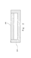
- Fig. 2 is a cross-sectional view of one of the rails 200 in accordance with one embodiment of the present invention.
- a plurality of covers 400 can be included to cover some rails 200.
- the covers 400 cover the rails 200, so as to prevent dust from falling into the rails 200, and to press against the rolling balls 140 (See Fig. 1 ), so that the rolling balls 140 do not move freely.
- the covers 400 tightly contact the rails 200.
- each of the rails 200 can be a U-shaped recess, and the corresponding cover 400 can be exactly contained in this U-shaped recess.
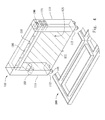
- Fig. 3 is a perspective view of the movable test chamber 100 in one operation state in accordance with one embodiment of the present invention
- Fig. 4 is a perspective view of the movable test chamber 100 of Fig. 3 in another operation state.
- the movable test chamber 100 includes a pair of walls 110, a passageway 120, a pair of heat insulation curtains 130, at least one heat source 150 and at least one pair of rolling balls 140.
- the walls 110 encompass the passageway 120.
- the heat insulation curtains 130 are retractable, and are used for covering opposite ends of the passageway 120.
- the heat insulation curtains 130 and the walls 110 form a test space 125.
- the heat source 150 is used for heating the test space 125.
- the rolling balls 140 are respectively positioned on the bottom surfaces 112 of the walls 110.
- the rolling balls 140 can be positioned under the movable test chamber 100, and the walls 110 encompass the passageway 120.
- the movable test chamber 100 can be moved in any direction or along a particular direction by rolling the rolling balls 140.
- the heat insulation curtain 130 is rolled up (See Fig. 3 )
- the passageway 120 can be moved to a particular position where the object to be tested can be contained in the movable test chamber 100.
- the heat insulation curtains 130 can be spread open or unfolded, and the heat insulation curtains 130 and the walls 110 form a test space 125.
- the heat source 150 can heat the test space 125 to increase the temperature of the test space 125 for accelerating the burn-in test.
- the movable test chamber 100 further includes at least one exhaust opening 160 for exhausting air from the passageway 120 to outside.
- the heat source 150 continuously provides thermal energy to the test space 125, the temperature of the test space 125 is increased continuously.
- the exhaust opening 160 can be employed to exhaust the hot air in the test space 125, so as to slow down the speed that the temperature increases.
- the exhaust opening 160 can be connected to an external exhaust hose (not shown), so as to accelerate the speed at which hot air is exhausted from the test space 125.
- the movable test chamber 100 further includes at least one intake window 170 for outside air entering into the passageway 120.
- cool air blows into the movable test chamber 100 through the intake window 170, so as to slow down the speed that the temperature increases.
- the movable test chamber 100 includes both the exhaust opening 160 and the intake window 170, so that hot air can be exhausted through the exhaust opening 160 and cool air can be blown into the movable test chamber 100 through the intake window 170. Therefore, the temperature can be maintained at a constant level. For example, the temperature of the test space 125 can be maintained at about 50 .
- the exhaust opening 160 can be formed on one of the walls 110, and the intake window 170 can be formed on another one of the walls 110 at an area that is opposite to the exhaust opening 160, so that the air can flow smoothly. For example, as shown in Fig. 3 and Fig. 4 , the exhaust opening 160 is formed on the wall 110 on the left side, and the intake window 170 is formed on the wall 110 on the right side.
- the movable test chamber 100 further includes at least one temperature sensor 180 which is used for detecting the temperature of the passageway 120.
- the temperature sensor 180 can be placed in the test space 125 to detect the temperature of the test space 125, so that the user can use the detected result to determine whether the temperature in the test space 125 is normal.
- the temperature sensor 180 can be positioned on the top of the movable test chamber 100 and between two heat sources 150.
- the movable test chamber 100 further includes at least one monitor 190 which is used for displaying the temperature that the temperature sensor 180 detects.
- the monitor 190 can be positioned on the outer surface of one of the walls 110. Therefore, the user can be informed of the temperature of the test space 125 by simply looking at the outer surface of the wall 110 of the movable test chamber 100.
- the monitor 190 and the intake window 170 can be formed on the same wall 110.
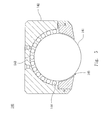
- the rolling ball 140 is a universal ball that can move in any direction.
- the rolling ball 140 may include a first sphere 141, a sphere base 142, an arc groove 143, a plurality of second spheres 144 and a gap 145.
- the arc groove 143 is formed in the sphere base 142.
- the second spheres 144 are contained in the arc groove 143 and press against the first sphere 141.
- the second spheres 144 can roll freely in the arc groove 143, and the first sphere 141 can roll freely relative to the second spheres 144.
- the first sphere 141 can roll in any direction, and as a result, the rolling ball 140 functions as a universal ball. Further, the gap 145 formed between the first sphere 141 and the sphere base 142 can prevent the first sphere 141 from contacting the sphere base 142 when rolling.
- the heat sources 150 can be arranged on the top of the movable test chamber 100 at equal or unequal intervals.
- Each of the heat sources 150 can be a radiator that converts electric power to generate thermal energy and that radiates the thermal energy to the test space 125.
- each of the heat sources 150 is not limited to being a radiator.
Landscapes
- Engineering & Computer Science (AREA)
- Environmental & Geological Engineering (AREA)
- Computer Hardware Design (AREA)
- Microelectronics & Electronic Packaging (AREA)
- General Engineering & Computer Science (AREA)
- Physics & Mathematics (AREA)
- General Physics & Mathematics (AREA)
- Testing Of Individual Semiconductor Devices (AREA)
- Testing Electric Properties And Detecting Electric Faults (AREA)
- Investigating Or Analyzing Materials Using Thermal Means (AREA)
- Testing Resistance To Weather, Investigating Materials By Mechanical Methods (AREA)
Abstract
Description
- Embodiments of the present invention relate to a test apparatus. More particularly, embodiments of the present invention relate to a test apparatus for a burn-in test and a movable test chamber thereof.
- In order to ensure reliability of electrical products, a burn-in test is required to be performed. When an electrical product undergoes a burn-in test at room temperature, more time is required to ensure reliability. For example, when a frequency converter undergoes a burn-in test at room temperature, 48 hours are necessary to accomplish the test, and such a long testing time results in increased costs and a high use of electricity. However, if the test time is reduced, reliability cannot be ensured.
- To overcome this dilemma, a high-temperature test chamber has been developed. Such a high-temperature test chamber can be maintained at a high temperature, and allows an electrical product to undergo a burn-in test while in a high temperature environment. As a result, the test time can be reduced.
- Typically, several products undergo a burn-in test simultaneously. In such a case, several high temperature test chambers are required. For example, if six frequency converters are to undergo a burn-in test simultaneously, six high temperature chambers are required. A serious cost burden is associated with requiring a separate test chamber for each product.
- A summary of certain embodiments disclosed herein is set forth below. It should be understood that these aspects are presented merely to provide the reader with a brief summary of these certain embodiments and that these aspects are not intended to limit the scope of this disclosure. Indeed, this disclosure may encompass a variety of aspects that may not be set forth below.
- In accordance with one embodiment of the present invention, a test apparatus includes a plurality of rails, a plurality of test zones and a movable test chamber. The test zones are located between the rails. The movable test chamber includes a passageway, at least one heat source and at least one pair of rolling balls. The heat source is used for heating the passageway. The rolling balls are respectively and movably contained in two of the rails, so as to facilitate movement of the passageway to different test zones.
- In accordance with another embodiment of the present invention, a movable test chamber includes a pair of walls, a passageway and a pair of heat insulation curtains, at least one heat source and at least one pair of rolling balls. The walls encompass the passageway. The heat insulation curtains are retractable, and are used for covering opposite ends of the passageway. The heat insulation curtains and the walls form a test space. The heat source is used for heating the test space. The rolling balls are respectively positioned on the bottom surfaces of the walls.
- It is to be understood that both the foregoing general description and the following detailed description are by examples, and are intended to provide further explanation of the invention as claimed.
- The invention can be more fully understood by reading the following detailed description of the embodiment, with reference made to the accompanying drawings as follows:
-
Fig. 1 is a schematic view of a test apparatus in accordance with one embodiment of the present invention; -
Fig. 2 is a cross-sectional view of a rail in accordance with one embodiment of the present invention; -
Fig. 3 is a perspective view of a movable test chamber in one operation state in accordance with one embodiment of the present invention; -
Fig. 4 is a perspective view of the movable test chamber ofFig. 3 in another operation state; and -
Fig. 5 is a cross-sectional view of a rolling ball in accordance with one embodiment of the present invention. - Reference will now be made in detail to the present embodiments of the invention, examples of which are illustrated in the accompanying drawings. Wherever possible, the same reference numbers are used in the drawings and the description to refer to the same or like parts.
-
Fig. 1 is a schematic view of a test apparatus in accordance with one embodiment of the present invention. As shown in this figure, the test apparatus includes a plurality ofrails 200, a plurality oftest zones 300 and amovable test chamber 100. Thetest zones 300 are located between therails 200. Themovable test chamber 100 includes apassageway 120, at least oneheat source 150 and at least one pair ofrolling balls 140. Theheat source 150 is used for heating thepassageway 120. Therolling balls 140 are respectively and movably contained in two of therails 200, so as to allow thepassageway 120 to be moved todifferent test zones 300. - In this embodiment, the
rolling balls 140 can be positioned under themovable test chamber 100 and can roll in therails 200. Because themovable test chamber 100 includes thepassageway 120, even if there are many objects to be tested respectively placed on thetest zones 300, themovable test chamber 100 can still move to eachtest zone 300 without being blocked by the objects and heat the objects using theheat source 150 to raise the temperature during a burn-in test. Therefore, in the embodiment of the present invention, only onemovable test chamber 100 is required to perform a burn-in test for several objects to be tested, such as a cabinet of a frequency converter. Therefore, the cost burden associated with having to use a plurality of test chambers can be reduced. - In some embodiments, the
movable test chamber 100 includes a pair ofwalls 110. Thewalls 110 encompass thepassageway 120. In some embodiments, therolling balls 140 are respectively positioned on thebottom surfaces 112 of thewalls 110. Specifically, thebottom surface 112 of eachwall 110 faces one of therails 200, and therolling ball 140 is positioned between thebottom surface 112 of thewall 110 and therail 200. Therefore, therolling ball 140 supports thewall 110 and is movably contained in therail 200. When therolling balls 140 move or roll in therails 200, thewalls 100 move, and as a result, themovable test chamber 100 moves. - In some embodiments, the
movable test chamber 100 further includes a pair ofheat insulation curtains 130. Theheat insulation curtains 130 are retractable, and are used for covering opposite ends of thepassageway 120. It is noted that by "retractably" it is meant that theheat insulation curtains 130 can be retracted by, for example, being rolled up from a state covering the opposite ends of thepassageway 120 to thereby expose the opposite ends of thepassageway 120. As shown inFig. 1 , thewalls 110 are respectively positioned on the left side and the right side of thepassageway 120, namely, opposite sides along an x-direction, and theheat insulation curtains 130 are respectively placed on the front end and the rear end of thepassageway 120, namely, opposite ends along a y-direction. When covering thepassageway 120, theheat insulation curtains 130 can prevent the thermal energy in thepassageway 120 from dissipating to the environment, so that theheat source 150 can increase the temperature in themovable test chamber 100 more quickly, thereby facilitating the performance of a burn-in test for objects such as a cabinet of a frequency converter. - Further, because the
heat insulation curtains 130 are retractable, and are used for covering opposite ends of thepassageway 120, as described above, theheat insulation curtains 130 can be rolled up whenever it is desired to move themovable test chamber 100. In some embodiments, theheat insulation curtains 130 can be formed by heat insulation material. Moreover, theheat insulation curtains 130 can be rolled up or unfolded by manual control or by power driving. - In some embodiments, the
rails 200 include a plurality oflongitudinal rails 210. Thetest zones 300 include a plurality ofregions 310 for objects to be tested. Theregions 310 for objects to be tested are arranged between thelongitudinal rails 210 along the length direction of thelongitudinal rails 210. As shown inFig. 1 , the length direction of thelongitudinal rails 210 is parallel to the y-direction, and theregions 310 for objects to be tested are arranged between twolongitudinal rails 210 along the y-direction. Twolongitudinal rails 210 encompass opposite sides of theregion 310 for objects to be tested. - In some embodiments, a normal line of the
passageway 120 is substantially parallel to the length direction of thelongitudinal rails 210. Specifically, the normal line of thepassageway 120 is parallel to the y-direction, and the length direction of thelongitudinal rails 210 is also parallel to the y-direction. It should be understood that the normal line of thepassageway 120 refers to an imaginary line that passes through the front end and the rear end of thepassageway 120. - When the rolling
balls 140 of themovable test chamber 100 roll in thelongitudinal rails 210, thepassageway 120 moves along the y-direction, and therefore, themovable test chamber 100 can be moved to anyregion 310 for objects to be tested, thereby facilitating a burn-in test for objects such as a cabinet of a frequency converter. - In some embodiments, the rails include a plurality of
latitudinal rails 220. Thelatitudinal rails 220 cross thelongitudinal rails 210. Thetest zones 300 include a plurality ofbuffering regions 320. Each of thebuffering regions 320 is encompassed by two of thelongitudinal rails 210 and two of thelatitudinal rails 220. As shown inFig. 1 , the length direction of thelatitudinal rails 220 is parallel to the x-direction. Twolongitudinal rails 210, which are parallel to the y-direction, and twolatitudinal rails 220, which are parallel to the x-direction, encompass abuffering region 320. In other words, twolatitudinal rails 220 respectively encompass the upper side and the lower side of one of thebuffering regions 320, and twolongitudinal rails 210 respectively encompass the left side and the right side of thebuffering region 320. - The main difference between the buffering
regions 320 and theregions 310 for objects to be tested is that no object, such as a cabinet of a frequency converter, is placed in thebuffering regions 320. Therefore, even though thewalls 110 are formed on opposite sides of themovable test chamber 100 in the x-direction, themovable test chamber 100 can move latitudinally (i.e., in the x-direction) via thebuffering regions 320. - Specifically, the rolling
balls 140 can move in thelatitudinal rails 220 in addition to moving in thelongitudinal rails 210. Therefore, for example, themovable test chamber 100 can be moved from theregion 310 on the left side to thebuffering region 320 on the left side along the direction of arrow A inFig. 1 , then can be moved from thebuffering region 320 on the left side to thebuffering region 320 on the right side along the direction of arrow B inFig. 1 . After being moved to thebuffering region 320 on the right side, themovable test chamber 100 can be moved upwardly to theregion 310 for objects to be tested on the right side along the direction of arrow C. In other words, thebuffering region 320 allows themovable test chamber 100 to be moved along the x-direction, so that themovable test chamber 100 is not limited to moving only along the y-direction. Therefore, themovable test chamber 100 can be moved to theregions 310 for objects to be tested that are between differentlongitudinal rails 210, rather than being limited to move between a particular pair of thelongitudinal rails 210 associated with oneparticular region 310. -
Fig. 2 is a cross-sectional view of one of therails 200 in accordance with one embodiment of the present invention. As shown inFig. 2 , a plurality ofcovers 400 can be included to cover somerails 200. Specifically, when themovable test chamber 100 is not moving, thecovers 400 cover therails 200, so as to prevent dust from falling into therails 200, and to press against the rolling balls 140 (SeeFig. 1 ), so that the rollingballs 140 do not move freely. In some embodiments, thecovers 400 tightly contact therails 200. For example, each of therails 200 can be a U-shaped recess, and thecorresponding cover 400 can be exactly contained in this U-shaped recess. -
Fig. 3 is a perspective view of themovable test chamber 100 in one operation state in accordance with one embodiment of the present invention, andFig. 4 is a perspective view of themovable test chamber 100 ofFig. 3 in another operation state. As shown inFig. 3 andFig. 4 , themovable test chamber 100 includes a pair ofwalls 110, apassageway 120, a pair ofheat insulation curtains 130, at least oneheat source 150 and at least one pair of rollingballs 140. Thewalls 110 encompass thepassageway 120. Theheat insulation curtains 130 are retractable, and are used for covering opposite ends of thepassageway 120. Theheat insulation curtains 130 and thewalls 110 form atest space 125. Theheat source 150 is used for heating thetest space 125. The rollingballs 140 are respectively positioned on the bottom surfaces 112 of thewalls 110. - In this embodiment, the rolling
balls 140 can be positioned under themovable test chamber 100, and thewalls 110 encompass thepassageway 120. Themovable test chamber 100 can be moved in any direction or along a particular direction by rolling the rollingballs 140. When theheat insulation curtain 130 is rolled up (SeeFig. 3 ), thepassageway 120 can be moved to a particular position where the object to be tested can be contained in themovable test chamber 100. When performing a burn-in test, theheat insulation curtains 130 can be spread open or unfolded, and theheat insulation curtains 130 and thewalls 110 form atest space 125. Theheat source 150 can heat thetest space 125 to increase the temperature of thetest space 125 for accelerating the burn-in test. - In some embodiments, the
movable test chamber 100 further includes at least oneexhaust opening 160 for exhausting air from thepassageway 120 to outside. Specifically, because theheat source 150 continuously provides thermal energy to thetest space 125, the temperature of thetest space 125 is increased continuously. However, it is preferred to maintain the temperature at a constant value such as 50 , rather than increasing the temperature on a continuous basis when performing the burn-in test. Therefore, theexhaust opening 160 can be employed to exhaust the hot air in thetest space 125, so as to slow down the speed that the temperature increases. In some embodiments, theexhaust opening 160 can be connected to an external exhaust hose (not shown), so as to accelerate the speed at which hot air is exhausted from thetest space 125. - In some embodiments, the
movable test chamber 100 further includes at least oneintake window 170 for outside air entering into thepassageway 120. In other words, cool air blows into themovable test chamber 100 through theintake window 170, so as to slow down the speed that the temperature increases. - In some embodiments, the
movable test chamber 100 includes both theexhaust opening 160 and theintake window 170, so that hot air can be exhausted through theexhaust opening 160 and cool air can be blown into themovable test chamber 100 through theintake window 170. Therefore, the temperature can be maintained at a constant level. For example, the temperature of thetest space 125 can be maintained at about 50 . Theexhaust opening 160 can be formed on one of thewalls 110, and theintake window 170 can be formed on another one of thewalls 110 at an area that is opposite to theexhaust opening 160, so that the air can flow smoothly. For example, as shown inFig. 3 andFig. 4 , theexhaust opening 160 is formed on thewall 110 on the left side, and theintake window 170 is formed on thewall 110 on the right side. - In some embodiments, the
movable test chamber 100 further includes at least onetemperature sensor 180 which is used for detecting the temperature of thepassageway 120. Specifically, thetemperature sensor 180 can be placed in thetest space 125 to detect the temperature of thetest space 125, so that the user can use the detected result to determine whether the temperature in thetest space 125 is normal. As shown inFig. 3 andFig. 4 , thetemperature sensor 180 can be positioned on the top of themovable test chamber 100 and between twoheat sources 150. - In some embodiments, the
movable test chamber 100 further includes at least onemonitor 190 which is used for displaying the temperature that thetemperature sensor 180 detects. Specifically, themonitor 190 can be positioned on the outer surface of one of thewalls 110. Therefore, the user can be informed of the temperature of thetest space 125 by simply looking at the outer surface of thewall 110 of themovable test chamber 100. As shown inFig. 3 andFig. 4 , themonitor 190 and theintake window 170 can be formed on thesame wall 110. - In some embodiments, the rolling
ball 140 is a universal ball that can move in any direction. For example, referring toFig. 5 , which is a cross-sectional view of the rollingball 140 in accordance with one embodiment of the present invention, the rollingball 140 may include afirst sphere 141, asphere base 142, anarc groove 143, a plurality ofsecond spheres 144 and agap 145. Thearc groove 143 is formed in thesphere base 142. Thesecond spheres 144 are contained in thearc groove 143 and press against thefirst sphere 141. Thesecond spheres 144 can roll freely in thearc groove 143, and thefirst sphere 141 can roll freely relative to thesecond spheres 144. Therefore, thefirst sphere 141 can roll in any direction, and as a result, the rollingball 140 functions as a universal ball. Further, thegap 145 formed between thefirst sphere 141 and thesphere base 142 can prevent thefirst sphere 141 from contacting thesphere base 142 when rolling. - Referring again to
Figs. 1 ,3 ,4 and5 , in some embodiments, theheat sources 150 can be arranged on the top of themovable test chamber 100 at equal or unequal intervals. Each of theheat sources 150 can be a radiator that converts electric power to generate thermal energy and that radiates the thermal energy to thetest space 125. In some embodiments, each of theheat sources 150 is not limited to being a radiator. - Although the present invention has been described in considerable detail with reference to certain embodiments thereof, other embodiments are possible. Therefore, the spirit and scope of the appended claims should not be limited to the description of the embodiments contained herein.
- It will be apparent to those skilled in the art that various modifications and variations can be made to the structure of the present invention without departing from the scope or spirit of the invention.
- In view of the foregoing, it is intended that the present invention cover modifications and variations of this invention provided they fall within the scope of the following claims
Claims (14)
- A test apparatus, comprising:a plurality of rails;a plurality of test zones located between the rails; anda movable test chamber comprising:a passageway;at least one heat source for heating the passageway; andat least one pair of rolling balls respectively and movably contained in two of the rails, so as to facilitate movement of the passageway to different test zones.
- The test apparatus of claim 1, wherein the movable test chamber comprises:a pair of walls encompassing the passageway, the rolling balls respectively being positioned on bottom surfaces of the walls.
- The test apparatus of claim 1, wherein the movable test chamber comprises:a pair of heat insulation curtains for covering opposite ends of the passageway.
- The test apparatus of claim 1, wherein the rails comprises:a plurality of longitudinal rails, wherein the test zones comprise a plurality of regions for objects to be tested, and the regions for objects to be tested are arranged between the longitudinal rails along the length direction of the longitudinal rails, and a normal line of the passageway is substantially parallel to the length direction of the longitudinal rails, wherein the normal line of the passageway is an imaginary line that passes through a front end and a rear end of the passageway.
- The test apparatus of claim 4, wherein the rails further comprise:a plurality of latitudinal rails crossing the longitudinal rails, wherein the test zones comprise a plurality of buffering regions, and each of the buffering regions is encompassed by two of the longitudinal rails and two of the latitudinal rails.
- The test apparatus of claim 1, wherein the movable test chamber comprises:at least one exhaust opening for exhausting air from the passageway to outside.
- The test apparatus of claim 1, wherein the movable test chamber comprises:at least one intake window for outside air entering into the passageway.
- The test apparatus of claim 1, wherein the movable test chamber comprises:at least one temperature sensor for detecting the temperature of the passageway.
- The test apparatus of claim 8, wherein the movable test chamber comprises:at least one monitor for displaying the temperature that the temperature sensor detects.
- A movable test chamber, comprising:a pair of walls;a passageway encompassed by the walls;a pair of heat insulation curtains for covering opposite ends of the passageway, wherein the heat insulation curtains and the walls form a test space;at least one heat source for heating the test space; andat least one pair of rolling balls respectively positioned on the bottom surfaces of the walls.
- The movable test chamber of claim 10, further comprising:at least one exhaust opening formed on one of the walls.
- The movable test chamber of claim 11, further comprising:at least one intake window formed on another one of the walls that is opposite to the exhaust opening.
- The movable test chamber of claim 10, further comprising:at least one temperature sensor placed in the test space and which detects the temperature in the test space.
- The movable test chamber of claim 10, further comprising:at least one monitor positioned on the outer surface of one of the walls, the monitor displaying the temperature that the temperature sensor detects.
Applications Claiming Priority (1)
| Application Number | Priority Date | Filing Date | Title |
|---|---|---|---|
| CN201210297922.4A CN103630767B (en) | 2012-08-20 | 2012-08-20 | Test equipment and its mobile test chamber |
Publications (2)
| Publication Number | Publication Date |
|---|---|
| EP2700960A2 true EP2700960A2 (en) | 2014-02-26 |
| EP2700960A3 EP2700960A3 (en) | 2017-03-08 |
Family
ID=47678457
Family Applications (1)
| Application Number | Title | Priority Date | Filing Date |
|---|---|---|---|
| EP12192779.2A Withdrawn EP2700960A3 (en) | 2012-08-20 | 2012-11-15 | Test apparatus and movable test chamber thereof |
Country Status (4)
| Country | Link |
|---|---|
| US (1) | US9523734B2 (en) |
| EP (1) | EP2700960A3 (en) |
| JP (1) | JP5568814B2 (en) |
| CN (1) | CN103630767B (en) |
Families Citing this family (3)
| Publication number | Priority date | Publication date | Assignee | Title |
|---|---|---|---|---|
| CN105445312B (en) * | 2015-01-04 | 2019-08-16 | 宁波英飞迈材料科技有限公司 | Micro zone heating device |
| CN110044960A (en) * | 2019-05-17 | 2019-07-23 | 上海纺织集团检测标准有限公司 | Curtain class product radiant temperature experimental rig and its detection method |
| CN114460391B (en) * | 2021-12-24 | 2022-12-16 | 江苏力普通瑞电力电子科技有限公司 | High-voltage inverter test system convenient to debug |
Family Cites Families (17)
| Publication number | Priority date | Publication date | Assignee | Title |
|---|---|---|---|---|
| US3478382A (en) * | 1967-07-03 | 1969-11-18 | Gen Bearing Co | Sealed ball transfer |
| US4527119A (en) * | 1982-05-17 | 1985-07-02 | Testamatic, Incorporated | High speed, low mass, movable probe and/or instrument positioner, tool and like items suitable for use in a controlled environment chamber |
| JPH0564750A (en) | 1991-09-06 | 1993-03-19 | Ube Ind Ltd | Vertical crusher |
| JPH0652226B2 (en) * | 1991-10-22 | 1994-07-06 | タバイエスペック株式会社 | Complex environment test equipment |
| US5191282A (en) * | 1991-10-23 | 1993-03-02 | Venturedyne, Ltd. | Unitized test system with bi-directional transport feature |
| FR2683259A1 (en) * | 1991-10-30 | 1993-05-07 | Nergeco Sa | LIFT CURTAIN DOOR WITH ACCESSIBLE SLIDES. |
| JPH0564750U (en) * | 1992-02-04 | 1993-08-27 | タバイエスペック株式会社 | Complex environmental testing device with vibration axis seal tube |
| US6607071B1 (en) * | 1998-10-19 | 2003-08-19 | Mirae Corporation | Sealed test chamber for module IC handler |
| JP3379532B2 (en) * | 2001-06-14 | 2003-02-24 | ミノルタ株式会社 | Electronic equipment and its inspection system |
| CN100387998C (en) * | 2006-02-06 | 2008-05-14 | 友达光电股份有限公司 | Burn-in equipment |
| JP5135911B2 (en) * | 2007-06-22 | 2013-02-06 | 富士通株式会社 | Temperature test booth and environment generation method in the temperature test booth |
| CN101769985B (en) * | 2008-12-30 | 2012-07-04 | 京元电子股份有限公司 | IC component burn-in equipment and the IC heating device used therein |
| US8970244B2 (en) * | 2009-09-26 | 2015-03-03 | Centipede Systems, Inc. | Transport apparatus for moving carriers of test parts |
| JP2011247784A (en) * | 2010-05-27 | 2011-12-08 | Fujitsu Ltd | Electronic component testing device and variable fin area radiator |
| TWM404979U (en) * | 2010-11-02 | 2011-06-01 | King Yuan Electronics Co Ltd | Pre-heating oven with frequencymodulation fan and heating adjustment device |
| CN201903484U (en) * | 2010-12-14 | 2011-07-20 | 中国地质大学(武汉) | Special testing box of loading system for MTS structure testing in high/low-temperature environment |
| JP2013033809A (en) * | 2011-08-01 | 2013-02-14 | Tokyo Electron Ltd | Wafer transfer apparatus |
-
2012
- 2012-08-20 CN CN201210297922.4A patent/CN103630767B/en not_active Expired - Fee Related
- 2012-11-08 US US13/671,787 patent/US9523734B2/en not_active Expired - Fee Related
- 2012-11-12 JP JP2012248200A patent/JP5568814B2/en not_active Expired - Fee Related
- 2012-11-15 EP EP12192779.2A patent/EP2700960A3/en not_active Withdrawn
Non-Patent Citations (1)
| Title |
|---|
| None |
Also Published As
| Publication number | Publication date |
|---|---|
| CN103630767B (en) | 2016-04-06 |
| US9523734B2 (en) | 2016-12-20 |
| JP5568814B2 (en) | 2014-08-13 |
| EP2700960A3 (en) | 2017-03-08 |
| CN103630767A (en) | 2014-03-12 |
| JP2014038079A (en) | 2014-02-27 |
| US20140049277A1 (en) | 2014-02-20 |
Similar Documents
| Publication | Publication Date | Title |
|---|---|---|
| US9523734B2 (en) | Test apparatus and movable test chamber thereof | |
| Singh et al. | Infrared thermography based diagnosis of inter-turn fault and cooling system failure in three phase induction motor | |
| CN212059994U (en) | A processor chip surface temperature testing device | |
| JP6435246B2 (en) | Environmental test equipment, sub-laboratory unit and combined test equipment | |
| KR20120115686A (en) | Apparatus for vacuum pressure check of multistage vacuum insulation panel and measuring method using the same | |
| CN110609224B (en) | PLC testing device and method | |
| CN103537326A (en) | Constant temperature cabinet and temperature measuring system | |
| KR102203467B1 (en) | Switch cabinets for exhaust gas measurement facilities | |
| CN109048245A (en) | Strip device is worn by a kind of band testing agency | |
| JP6135295B2 (en) | Conveyor belt support roller climbing resistance measurement device | |
| CN105486725B (en) | A kind of detecting system and its application method of aluminum alloy pretensioning plate conductivity value | |
| CN105870796A (en) | Cooling type electrical cabinet with adjustable inner space | |
| CN119355035A (en) | A method for testing the thermal insulation performance of a thermos bottle | |
| CN220794940U (en) | Fireproof coating quality detection equipment | |
| Janbakhsh et al. | A newly designed supply diffuser for industrial premises | |
| KR101140845B1 (en) | Apron | |
| CN104959176B (en) | A kind of temperature measuring equipment of round-bottomed flask | |
| CN210534289U (en) | Heat resistance test equipment of battery | |
| WO2015156529A1 (en) | Substrate heating device | |
| JP2013107119A (en) | Measuring device and measuring method | |
| JP7013362B2 (en) | Environmental test equipment | |
| KR101350449B1 (en) | Base for batch annealing furnance | |
| KR101207733B1 (en) | Method for measuring the temperature of strip | |
| CN215953760U (en) | Electronic high-temperature-resistant detection equipment for circuit board | |
| KR101779037B1 (en) | using the Peltier Heat-Cool temperature Control Module for Massage device |
Legal Events
| Date | Code | Title | Description |
|---|---|---|---|
| PUAI | Public reference made under article 153(3) epc to a published international application that has entered the european phase |
Free format text: ORIGINAL CODE: 0009012 |
|
| 17P | Request for examination filed |
Effective date: 20121115 |
|
| AK | Designated contracting states |
Kind code of ref document: A2 Designated state(s): AL AT BE BG CH CY CZ DE DK EE ES FI FR GB GR HR HU IE IS IT LI LT LU LV MC MK MT NL NO PL PT RO RS SE SI SK SM TR |
|
| AX | Request for extension of the european patent |
Extension state: BA ME |
|
| PUAL | Search report despatched |
Free format text: ORIGINAL CODE: 0009013 |
|
| AK | Designated contracting states |
Kind code of ref document: A3 Designated state(s): AL AT BE BG CH CY CZ DE DK EE ES FI FR GB GR HR HU IE IS IT LI LT LU LV MC MK MT NL NO PL PT RO RS SE SI SK SM TR |
|
| AX | Request for extension of the european patent |
Extension state: BA ME |
|
| RIC1 | Information provided on ipc code assigned before grant |
Ipc: G01R 31/28 20060101AFI20170202BHEP |
|
| RBV | Designated contracting states (corrected) |
Designated state(s): AL AT BE BG CH CY CZ DE DK EE ES FI FR GB GR HR HU IE IS IT LI LT LU LV MC MK MT NL NO PL PT RO RS SE SI SK SM TR |
|
| GRAP | Despatch of communication of intention to grant a patent |
Free format text: ORIGINAL CODE: EPIDOSNIGR1 |
|
| STAA | Information on the status of an ep patent application or granted ep patent |
Free format text: STATUS: GRANT OF PATENT IS INTENDED |
|
| INTG | Intention to grant announced |
Effective date: 20180719 |
|
| STAA | Information on the status of an ep patent application or granted ep patent |
Free format text: STATUS: THE APPLICATION IS DEEMED TO BE WITHDRAWN |
|
| 18D | Application deemed to be withdrawn |
Effective date: 20181130 |