EP2700863B1 - Hydraulic joint structure, hydraulic operation device with hydraulic joint structure, joint portion constituting hydraulic joint structure, hydraulic pressure generation unit with joint portion, front end tool unit with joint portion, and hydraulic hose unit with joint portion - Google Patents
Hydraulic joint structure, hydraulic operation device with hydraulic joint structure, joint portion constituting hydraulic joint structure, hydraulic pressure generation unit with joint portion, front end tool unit with joint portion, and hydraulic hose unit with joint portion Download PDFInfo
- Publication number
- EP2700863B1 EP2700863B1 EP12774904.2A EP12774904A EP2700863B1 EP 2700863 B1 EP2700863 B1 EP 2700863B1 EP 12774904 A EP12774904 A EP 12774904A EP 2700863 B1 EP2700863 B1 EP 2700863B1
- Authority
- EP
- European Patent Office
- Prior art keywords
- joint portion
- hydraulic
- oil passage
- joint
- open end
- Prior art date
- Legal status (The legal status is an assumption and is not a legal conclusion. Google has not performed a legal analysis and makes no representation as to the accuracy of the status listed.)
- Active
Links
- 238000004891 communication Methods 0.000 claims description 16
- 239000003921 oil Substances 0.000 description 160
- 239000010720 hydraulic oil Substances 0.000 description 54
- 230000007935 neutral effect Effects 0.000 description 7
- 239000000470 constituent Substances 0.000 description 4
- 238000000034 method Methods 0.000 description 3
- 238000003462 Bender reaction Methods 0.000 description 1
- 238000005452 bending Methods 0.000 description 1
- 238000010276 construction Methods 0.000 description 1
- 238000005553 drilling Methods 0.000 description 1
- 238000003780 insertion Methods 0.000 description 1
- 230000037431 insertion Effects 0.000 description 1
- 230000004048 modification Effects 0.000 description 1
- 238000012986 modification Methods 0.000 description 1
- 238000000926 separation method Methods 0.000 description 1
- 239000011343 solid material Substances 0.000 description 1
Images


Classifications
-
- F—MECHANICAL ENGINEERING; LIGHTING; HEATING; WEAPONS; BLASTING
- F16—ENGINEERING ELEMENTS AND UNITS; GENERAL MEASURES FOR PRODUCING AND MAINTAINING EFFECTIVE FUNCTIONING OF MACHINES OR INSTALLATIONS; THERMAL INSULATION IN GENERAL
- F16L—PIPES; JOINTS OR FITTINGS FOR PIPES; SUPPORTS FOR PIPES, CABLES OR PROTECTIVE TUBING; MEANS FOR THERMAL INSULATION IN GENERAL
- F16L39/00—Joints or fittings for double-walled or multi-channel pipes or pipe assemblies
- F16L39/02—Joints or fittings for double-walled or multi-channel pipes or pipe assemblies for hoses
-
- F—MECHANICAL ENGINEERING; LIGHTING; HEATING; WEAPONS; BLASTING
- F16—ENGINEERING ELEMENTS AND UNITS; GENERAL MEASURES FOR PRODUCING AND MAINTAINING EFFECTIVE FUNCTIONING OF MACHINES OR INSTALLATIONS; THERMAL INSULATION IN GENERAL
- F16L—PIPES; JOINTS OR FITTINGS FOR PIPES; SUPPORTS FOR PIPES, CABLES OR PROTECTIVE TUBING; MEANS FOR THERMAL INSULATION IN GENERAL
- F16L37/00—Couplings of the quick-acting type
- F16L37/28—Couplings of the quick-acting type with fluid cut-off means
- F16L37/30—Couplings of the quick-acting type with fluid cut-off means with fluid cut-off means in each of two pipe-end fittings
- F16L37/32—Couplings of the quick-acting type with fluid cut-off means with fluid cut-off means in each of two pipe-end fittings at least one of two lift valves being opened automatically when the coupling is applied
-
- A—HUMAN NECESSITIES
- A62—LIFE-SAVING; FIRE-FIGHTING
- A62B—DEVICES, APPARATUS OR METHODS FOR LIFE-SAVING
- A62B3/00—Devices or single parts for facilitating escape from buildings or the like, e.g. protection shields, protection screens; Portable devices for preventing smoke penetrating into distinct parts of buildings
- A62B3/005—Rescue tools with forcing action
-
- B—PERFORMING OPERATIONS; TRANSPORTING
- B25—HAND TOOLS; PORTABLE POWER-DRIVEN TOOLS; MANIPULATORS
- B25F—COMBINATION OR MULTI-PURPOSE TOOLS NOT OTHERWISE PROVIDED FOR; DETAILS OR COMPONENTS OF PORTABLE POWER-DRIVEN TOOLS NOT PARTICULARLY RELATED TO THE OPERATIONS PERFORMED AND NOT OTHERWISE PROVIDED FOR
- B25F3/00—Associations of tools for different working operations with one portable power-drive means; Adapters therefor
-
- B—PERFORMING OPERATIONS; TRANSPORTING
- B25—HAND TOOLS; PORTABLE POWER-DRIVEN TOOLS; MANIPULATORS
- B25F—COMBINATION OR MULTI-PURPOSE TOOLS NOT OTHERWISE PROVIDED FOR; DETAILS OR COMPONENTS OF PORTABLE POWER-DRIVEN TOOLS NOT PARTICULARLY RELATED TO THE OPERATIONS PERFORMED AND NOT OTHERWISE PROVIDED FOR
- B25F5/00—Details or components of portable power-driven tools not particularly related to the operations performed and not otherwise provided for
- B25F5/005—Hydraulic driving means
-
- B—PERFORMING OPERATIONS; TRANSPORTING
- B66—HOISTING; LIFTING; HAULING
- B66C—CRANES; LOAD-ENGAGING ELEMENTS OR DEVICES FOR CRANES, CAPSTANS, WINCHES, OR TACKLES
- B66C3/00—Load-engaging elements or devices attached to lifting or lowering gear of cranes or adapted for connection therewith and intended primarily for transmitting lifting forces to loose materials; Grabs
- B66C3/005—Grab supports, e.g. articulations; Oscillation dampers; Orientation
-
- E—FIXED CONSTRUCTIONS
- E02—HYDRAULIC ENGINEERING; FOUNDATIONS; SOIL SHIFTING
- E02F—DREDGING; SOIL-SHIFTING
- E02F3/00—Dredgers; Soil-shifting machines
- E02F3/04—Dredgers; Soil-shifting machines mechanically-driven
- E02F3/28—Dredgers; Soil-shifting machines mechanically-driven with digging tools mounted on a dipper- or bucket-arm, i.e. there is either one arm or a pair of arms, e.g. dippers, buckets
- E02F3/36—Component parts
- E02F3/3604—Devices to connect tools to arms, booms or the like
- E02F3/3677—Devices to connect tools to arms, booms or the like allowing movement, e.g. rotation or translation, of the tool around or along another axis as the movement implied by the boom or arms, e.g. for tilting buckets
- E02F3/3681—Rotators
-
- F—MECHANICAL ENGINEERING; LIGHTING; HEATING; WEAPONS; BLASTING
- F16—ENGINEERING ELEMENTS AND UNITS; GENERAL MEASURES FOR PRODUCING AND MAINTAINING EFFECTIVE FUNCTIONING OF MACHINES OR INSTALLATIONS; THERMAL INSULATION IN GENERAL
- F16L—PIPES; JOINTS OR FITTINGS FOR PIPES; SUPPORTS FOR PIPES, CABLES OR PROTECTIVE TUBING; MEANS FOR THERMAL INSULATION IN GENERAL
- F16L37/00—Couplings of the quick-acting type
- F16L37/28—Couplings of the quick-acting type with fluid cut-off means
- F16L37/30—Couplings of the quick-acting type with fluid cut-off means with fluid cut-off means in each of two pipe-end fittings
- F16L37/32—Couplings of the quick-acting type with fluid cut-off means with fluid cut-off means in each of two pipe-end fittings at least one of two lift valves being opened automatically when the coupling is applied
- F16L37/34—Couplings of the quick-acting type with fluid cut-off means with fluid cut-off means in each of two pipe-end fittings at least one of two lift valves being opened automatically when the coupling is applied at least one of the lift valves being of the sleeve type, i.e. a sleeve is telescoped over an inner cylindrical wall
-
- F—MECHANICAL ENGINEERING; LIGHTING; HEATING; WEAPONS; BLASTING
- F16—ENGINEERING ELEMENTS AND UNITS; GENERAL MEASURES FOR PRODUCING AND MAINTAINING EFFECTIVE FUNCTIONING OF MACHINES OR INSTALLATIONS; THERMAL INSULATION IN GENERAL
- F16L—PIPES; JOINTS OR FITTINGS FOR PIPES; SUPPORTS FOR PIPES, CABLES OR PROTECTIVE TUBING; MEANS FOR THERMAL INSULATION IN GENERAL
- F16L37/00—Couplings of the quick-acting type
- F16L37/56—Couplings of the quick-acting type for double-walled or multi-channel pipes or pipe assemblies
-
- F—MECHANICAL ENGINEERING; LIGHTING; HEATING; WEAPONS; BLASTING
- F16—ENGINEERING ELEMENTS AND UNITS; GENERAL MEASURES FOR PRODUCING AND MAINTAINING EFFECTIVE FUNCTIONING OF MACHINES OR INSTALLATIONS; THERMAL INSULATION IN GENERAL
- F16L—PIPES; JOINTS OR FITTINGS FOR PIPES; SUPPORTS FOR PIPES, CABLES OR PROTECTIVE TUBING; MEANS FOR THERMAL INSULATION IN GENERAL
- F16L39/00—Joints or fittings for double-walled or multi-channel pipes or pipe assemblies
-
- B—PERFORMING OPERATIONS; TRANSPORTING
- B23—MACHINE TOOLS; METAL-WORKING NOT OTHERWISE PROVIDED FOR
- B23D—PLANING; SLOTTING; SHEARING; BROACHING; SAWING; FILING; SCRAPING; LIKE OPERATIONS FOR WORKING METAL BY REMOVING MATERIAL, NOT OTHERWISE PROVIDED FOR
- B23D17/00—Shearing machines or shearing devices cutting by blades pivoted on a single axis
- B23D17/02—Shearing machines or shearing devices cutting by blades pivoted on a single axis characterised by drives or gearings therefor
- B23D17/06—Shearing machines or shearing devices cutting by blades pivoted on a single axis characterised by drives or gearings therefor actuated by fluid or gas pressure
-
- B—PERFORMING OPERATIONS; TRANSPORTING
- B23—MACHINE TOOLS; METAL-WORKING NOT OTHERWISE PROVIDED FOR
- B23D—PLANING; SLOTTING; SHEARING; BROACHING; SAWING; FILING; SCRAPING; LIKE OPERATIONS FOR WORKING METAL BY REMOVING MATERIAL, NOT OTHERWISE PROVIDED FOR
- B23D29/00—Hand-held metal-shearing or metal-cutting devices
- B23D29/002—Hand-held metal-shearing or metal-cutting devices for cutting wire or the like
-
- F—MECHANICAL ENGINEERING; LIGHTING; HEATING; WEAPONS; BLASTING
- F16—ENGINEERING ELEMENTS AND UNITS; GENERAL MEASURES FOR PRODUCING AND MAINTAINING EFFECTIVE FUNCTIONING OF MACHINES OR INSTALLATIONS; THERMAL INSULATION IN GENERAL
- F16L—PIPES; JOINTS OR FITTINGS FOR PIPES; SUPPORTS FOR PIPES, CABLES OR PROTECTIVE TUBING; MEANS FOR THERMAL INSULATION IN GENERAL
- F16L37/00—Couplings of the quick-acting type
- F16L37/28—Couplings of the quick-acting type with fluid cut-off means
- F16L37/30—Couplings of the quick-acting type with fluid cut-off means with fluid cut-off means in each of two pipe-end fittings
- F16L37/32—Couplings of the quick-acting type with fluid cut-off means with fluid cut-off means in each of two pipe-end fittings at least one of two lift valves being opened automatically when the coupling is applied
- F16L37/35—Couplings of the quick-acting type with fluid cut-off means with fluid cut-off means in each of two pipe-end fittings at least one of two lift valves being opened automatically when the coupling is applied at least one of the valves having an axial bore
-
- F—MECHANICAL ENGINEERING; LIGHTING; HEATING; WEAPONS; BLASTING
- F16—ENGINEERING ELEMENTS AND UNITS; GENERAL MEASURES FOR PRODUCING AND MAINTAINING EFFECTIVE FUNCTIONING OF MACHINES OR INSTALLATIONS; THERMAL INSULATION IN GENERAL
- F16L—PIPES; JOINTS OR FITTINGS FOR PIPES; SUPPORTS FOR PIPES, CABLES OR PROTECTIVE TUBING; MEANS FOR THERMAL INSULATION IN GENERAL
- F16L37/00—Couplings of the quick-acting type
- F16L37/28—Couplings of the quick-acting type with fluid cut-off means
- F16L37/30—Couplings of the quick-acting type with fluid cut-off means with fluid cut-off means in each of two pipe-end fittings
- F16L37/367—Couplings of the quick-acting type with fluid cut-off means with fluid cut-off means in each of two pipe-end fittings with two gate valves or sliding valves
-
- Y—GENERAL TAGGING OF NEW TECHNOLOGICAL DEVELOPMENTS; GENERAL TAGGING OF CROSS-SECTIONAL TECHNOLOGIES SPANNING OVER SEVERAL SECTIONS OF THE IPC; TECHNICAL SUBJECTS COVERED BY FORMER USPC CROSS-REFERENCE ART COLLECTIONS [XRACs] AND DIGESTS
- Y10—TECHNICAL SUBJECTS COVERED BY FORMER USPC
- Y10T—TECHNICAL SUBJECTS COVERED BY FORMER US CLASSIFICATION
- Y10T137/00—Fluid handling
- Y10T137/598—With repair, tapping, assembly, or disassembly means
Definitions
- the present invention relates to improvement in a hydraulic joint structure used in a hydraulically-actuated device.
- Rebar cutters and rebar benders have been conventionally known as a portable hydraulic tool (hydraulically-actuated device).
- a portable hydraulic tool includes, for example, a battery-driven hydraulic pump unit (hydraulic pressure generating unit) and an end tool unit (head unit) such as a cutter unit or a bending unit that is driven by a pressurized hydraulic oil supplied from the hydraulic pump unit.
- a hydraulic tool is used also as a rescue tool.
- the hydraulic pump unit and the end tool unit can be connected and separated to and from each other.
- the hydraulic pump unit and the end tool unit are connected through a relatively long hydraulic hose unit.
- a main operator holds and operates the end tool unit
- a sub operator holds and operates the hydraulic pump unit.
- the aforementioned portable hydraulic tool is classified into a single-acting type (in which only the forward action is performed hydraulically, while the backward action is performed by a return spring) and a double-acting type (in which both the forward and backward actions are performed hydraulically).
- a double-acting portable hydraulic tool two hydraulic oil lines are provided between the hydraulic pump unit and the end tool unit. One of the hydraulic oil lines is used for feeding pressurized hydraulic oil to the end tool unit, and the other is used for return oil.
- the portable hydraulic tool is composed of a plurality of connectable/separable units as described above, the hydraulic oil lines (oil passages) must be connected/separated.
- couplers or joints for constituting a hydraulic joint structure are provided on the respective units.
- Patent Document 1 An example of a hydraulic joint structure for a double-acting hydraulic tool, which includes a plurality of connectable/separable units, is disclosed in Patent Document 1 (Publication of Examined Patent Application No. JPH05-037796B2 ).
- Patent Document 1 describes that two holes into which both a porting connector and a coupler can be inserted are provided in an end surface of each unit, and two hydraulic oil lines are connected by using two porting connectors, with the end surfaces of the two units being abutted with each other; or a male coupler and a female coupler are engaged with the holes by screw fastening, and the couplers are connected with each other when two units are joined.
- Document JP 2005 114150 A discloses a multitubular piping device which is formed with a multitubular joint part carrying out insertion holding of the multitubular tube having the plurality of passages in the tube.
- a release bushing, a guide, and a chuck are formed in a multitubular tube side of the multitubular joint part.
- a plurality of passage tubes are formed in a center part.
- a passage piping formed in an interior of a passage protecting tube is conducted to the passage tube, and a plurality of the passage tubings are formed in the same direction.
- a plurality of passage holes are formed for inserting the passage protecting tube, a plurality of conductive delivery holes are formed in correspondence to tube grooves of the inserted passage protecting tube, and a plurality of the multitubular piping devices are inserted and fixed in the passage holes.
- the object of the present invention is to provide a hydraulic joint structure capable of easily connecting two hydraulic oil lines at the same time.
- first joint portion according to claim 1 a second joint portion according to claim 2
- a hydraulic joint structure according to claim 3 a hydraulic pressure generating unit according to claim 7
- an end tool unit according to claim 8 a hydraulic hose unit according to claim 9
- a hydraulic joint structure capable of preventing leakage of hydraulic oil, when the hydraulic joint structure is in a separated condition.
- a hydraulic joint structure capable of preventing spout of a hydraulic oil or damage of a hydraulic pressure generating unit, even when the hydraulic pressure generating unit is operated while a hydraulic joint structure is in a separated condition.
- the two oil passages can be connected at the same time only by inserting the male member into the female member, a connecting operation is easy.
- the ring member having an inner circumference provided therein with a communication groove is disposed above the male member, leakage of hydraulic oil can be prevented while the hydraulic joint structure is in a separated condition.
- Oil passages shown in the accompanying drawings are formed by drilling a solid material with a drill to form a plurality of linear holes, connecting crosswise the linear holes according to need, and/or closing the end portions of the holes with plugs according to need. Since the specific method for forming the oil passages can be readily understood by those skilled in the art only from the accompanying drawings, the method is not described in the specification. It goes without saying that the hydraulically-actuated device may be a hydraulic tool, such as a rebar cutter or a rebar bender, which has been widely used in the construction industry.
- the hydraulic rescue tool is composed of: a hydraulic pressure generating unit 100; a double-acting end tool unit 200 (which is also called “head unit”) which is a spreader in this embodiment and which is driven by a hydraulic pressure generated by the hydraulic pressure generating unit 100; and a hydraulic hose unit (hereinafter referred to simply as "hose unit") 300 that connects the hydraulic pressure generating unit 100 and the end tool unit 200 with each other.
- the hydraulic pressure generating unit 100 and the hose unit 300 can be connected and separated to and from each other.
- the end tool unit 200 and the hose unit 300 can be connected and separated to and from each other.
- the hydraulic pressure generating unit 100 and the end tool unit can be directly connected with each other, without using the hose unit 300.
- Fig. 1 shows the condition in which the hydraulic pressure generating unit 100, the end tool unit 200 and the hose unit 300 are connected.
- Fig. 2 shows, in enlargement, a hydraulic joint structure C that connects the hydraulic pressure generating unit 100 and the hose unit 300 with each other.
- Fig. 3 shows the condition in which the hydraulic pressure generating unit 100 and the hose unit 300 are separated from each other.
- the hydraulic pressure generating unit 100 comprises a battery-powered electrohydraulic pump unit.
- the hydraulic pressure generating unit 100 includes a grip 102 provided with a trigger switch 104.
- an electric motor 106 (invisible in Fig. 1 ) incorporated in the hydraulic pressure generating unit 100 operates to rotate a pump 108, so that a pressurized hydraulic oil is fed to an oil discharge passage 110. Then, the hydraulic oil is returned to the pump 108 through an oil return passage 112.
- a battery 103 as an electric power source for driving the electric motor 106 is mounted on the lower end of the grip 102.
- the spreader as the end tool unit 200 is a double-acting tool unit including a double-acting hydraulic cylinder 202. Namely, both the opening operation and closing operation of the spreader are performed hydraulically.
- a piston 204 and a rod 206 fixed to the piston 204 are moved rightward in Fig. 1 , so that a pair of blades 208 of the spreader 200 are opened and that hydraulic oil in a second chamber 202b is pushed out therefrom through a second oil passage 201b.
- the hose unit 300 includes a pair of hydraulic hoses 302a and 302b.
- the hydraulic hoses 302a and 302b and the chambers 202a and 202b are respectively connected with each other.
- the relation of connection can be switched and interrupted by a second switch mechanism SW2 (described later).
- the hydraulic pressure generating unit 100 and the hose unit 300 are connected by the hydraulic joint structure C.
- the oil discharge passage 110 formed in a body of the hydraulic pressure generating unit 100 can be communicated with either one of the two hydraulic hoses 302a and 302b of the hose unit 300, depending on the condition of a first switch mechanism SW1.
- the first switch mechanism SW1 is described herebelow.
- Fig. 2 shows the condition in which pressurized hydraulic oil is supplied from the oil discharge passage 110 of the pump 108 to the first hydraulic hose 302a.
- a cylindrical spool valve element 120 is axially-slidably fitted in a spool valve hole formed in the body of the hydraulic pressure generating unit 100.
- An inside space 122 extending axially in the spool valve element 120 defines the aforementioned oil return passage 112 for returning hydraulic oil to the pump 108.
- the spool valve element 120 can be displaced by moving a lever 121 by a finger of a user.
- first position the position of the spool valve element 120 shown in Fig. 2 is referred to as "first position" in this specification.
- a first oil passage 114 and a second oil passage 116 are formed in the body of the hydraulic pressure generating unit 100.
- the oil passages 114, 110 and 116 open into an inner circumference of the spool valve hole in which the spool valve member 120 is inserted, which oil passages are spaced at equal intervals along the axial direction of the spool valve hole.
- An outer circumference of the spool valve element 120 is provided with three circumferential grooves 123, 124 and 125 which are arranged in the axial direction of the spool valve element 120.
- the spool 120 has radial holes that connect the narrower circumferential grooves 123 and 125 on both sides with the inside space 122 serving as the oil return passage 112.
- the middle circumferential groove 124 has such a large width that the groove 124 can communicate adjacent two oil passages (110 and 114, or 110 and 116) with each other depending on the axial position of the spool valve element 120.
- the oil discharge passage 110 is connected with the first oil passage 114 through the circumferential groove 124 of the spool valve element 120.
- the second oil passage 116 is connected with the inside space 122 of the spool valve element 120, i.e., the oil return passage 112, through the circumferential groove 125 of the spool valve element 120 and the radial hole connected with the circumferential groove 125.
- the oil discharge passage 110 is connected with the second oil passage 116 through the circumferential groove 124 of the spool 120; and the first oil passage 114 is connected with the inside space 122 of the spool 120, i.e., the oil return passage 112, through the circumferential groove 123 of the spool 120 and the radial hole connected with the circumferential groove 123.
- the hydraulic joint structure C for joining the hydraulic pressure generating unit 100 and the hydraulic hose unit 300, is described with reference to Figs. 2 and 3 .
- the hydraulic joint structure C includes a first joint portion C1 and a second joint portion C2 that are configured to be connectable and separable to and from each other.
- the first joint portion C1 is disposed on an end of the hydraulic pressure generating unit 100
- the second joint portion C2 is disposed on an end of the hydraulic hose unit 300 on the side of the hydraulic pressure generating unit 100.
- the first joint portion C1 has an outer cylinder 130 having generally a shape of a cylindrical sleeve and a mandrel 132 (i.e., a male member of the first joint portion C1) having a shape of a cylindrical column, which are parts of the body of the hydraulic pressure generating unit 100.
- the central axis of the outer cylinder 130 and a central axis of the mandrel 132 coincide with each other.
- a ring member 134 having a shape of cylindrical sleeve is provided in a space, which has a shape of a circular ring and is defined between an inner circumference of the outer cylinder 130 and an outer circumference of the mandrel 132.
- the ring member 134 is axially movable (slidable), with its inner circumference being guided by the outer circumference of the mandrel 132 and its outer circumference being guided by the inner circumference of the outer cylinder 130.
- the ring member 134 is biased leftward in the drawings by a spring 136.
- a stopper 138 which comprises a bolt in the illustrated example, is provided to properly position the ring member 134 at the "oil passage-covering position".
- the stopper 138 is received in an axial groove 140 formed in the outer circumference of the ring member 134.
- the stopper 138 is in contact with a stop surface 141 provided on an end portion of the ring member 134 (see Fig. 3 ).
- the aforementioned first oil passage 114 and the second oil passage 116 axially extend in the cylindrical mandrel 132, i.e., the male member.
- the first oil passage 114 has an open end portion 114a opening into the outer circumference of the mandrel 132 at a first axial position of the mandrel 132.
- the second oil passage 116 has an open end portion 116a opening into the outer circumference of the mandrel 132 at a second axial position of the mandrel 132 (i.e., a position on the left side of the first axial position in the illustrated example).
- a circumferential groove 142 is formed in the inner circumference of the ring member 134.
- the circumferential groove 142 is configured such that, when the ring member 134 is positioned at the "oil passage-covering position", the circumferential groove 142 occupies such a position and has such a width that allow the open end portion 114a and the open end portion 116a to be communicated with each other.
- Ring-shaped seal members 144 are provided on the inner circumference of the ring member 134, on both sides of the circumferential groove 142.
- the second joint portion C2 which is provided on the end of the hydraulic hose unit 300 on the side of the hydraulic pressure generating unit 100, includes a generally cylindrical sleeve 304 (i.e., a female member of the second joint portion C2) having an axially-extending inside space formed in its central portion.
- a first oil passage 306 in communication with a first hydraulic hose 302a
- a second oil passage 308 in communication with a second hydraulic hose 302b.
- the first oil passage 306 has an open end portion 306a opening into an inner circumference of the sleeve 304 at a first axial position of the sleeve 304.
- the second oil passage 308 has an open end portion 308a opening into the inner circumference of the sleeve 304 at a second axial position of the sleeve 304 (i.e., a position on the left side of the first axial position in the illustrated embodiment).
- a circumferential groove 306b in communication with the open end portion 306a is formed in the inner circumference of the sleeve 304 at the same axial position as that of the open end portion 306a.
- a circumferential groove 308b in communication with the open end portion 308a is formed in the inner circumference of the sleeve 304 at the same axial position as that of the open end portion 308b.
- the axial distance between the circumferential groove 306a and the circumferential groove 308b is the same as the axial distance between the open end portion 114a and the open end portion 116a, which are provided in the mandrel 132 of the first joint portion C1.
- the diameter of the inner circumference of the sleeve 304 is slightly larger than the diameter of the mandrel 132 of the first joint portion C1 (like "loose fit"), so that the mandrel 132 can be smoothly inserted into the sleeve 304.
- a rod member 312 having a shape of a cylindrical column is disposed in the sleeve 304.
- the rod member 312 is axially movable (slidable) in the sleeve 304.
- the rod member 312 is biased rightward in the drawings by a spring 314. As shown in Fig.
- a stopper 316 which comprises a step formed in the inner circumference of the cylindrical sleeve 304 in the illustrated embodiment, is provided to properly position the rod member 312 at the "oil passage-covering position".
- the stopper 316 is in contact with a stop surface 318, which comprises a surface of an enlarged diameter portion provided at an end portion of the rod member 312.
- the rod member 312 When the rod member 312 is positioned at the "oil passage-covering position", the rod member 312 closes the open end portion 306a of the first oil passage 306 and the circumferential groove 306b in communication therewith, as well as the open end portion 308a of the second oil passage 308 and the circumferential groove 308b in communication therewith.
- Three ring-shaped seal members 320, 322 and 324 are disposed on the inner circumference of the sleeve 304.
- the open end portion 306a of the first oil passage 306 (and the circumferential groove 306b) opens into the inner circumference of the sleeve 304 at the first axial position of the sleeve 304 between the seal member 322 and the seal member 324.
- the open end portion 308a of the second oil passage 308 (and the circumferential groove 308b) opens into the inner circumference of the sleeve 304 at the second axial position of the sleeve 304 between the seal member 320 and the seal member 322.
- the condition shown in Fig. 3 will be changed into the condition shown in Fig. 2 .
- the mandrel 132 i.e., male member
- the sleeve 304 i.e., female member
- the end surface of the sleeve 304 pushes the ring member 134 rightward in Fig. 2 , while compressing the spring 136.
- the positions of the ring member 134 and the rod member 312 in this condition are referred to as "retracted positions".
- the first axial position of the outer circumference of the mandrel 132 and the first axial position of the inner circumference of the sleeve 304 are opposed to each other, and the second axial position of the outer circumference of the mandrel 132 and the second axial position of the inner circumference of the sleeve 304 are opposed to each other.
- the open end portion 114a of the first oil passage 114 of the hydraulic pressure generating unit 100 and the open end portion 306a of the first oil passage 306 of the hydraulic hose unit 300 are connected via the circumferential groove 306b to form a first connection.
- the open end portion 116a of the second oil passage 116 of the hydraulic pressure generating unit 100 and the open end portion 308a of the second oil passage 308 of the hydraulic hose unit 300 are connected via the circumferential groove 308b to form a second connection.
- the seal members 320, 322 and 324 seal a gap between the outer circumference of the mandrel 132 and the inner circumference of the sleeve 304.
- the seal members 320 and 322 are positioned at both axial sides of the connection between the open end portion 114a, and the open end portion 306a and the circumferential groove 306b to seal the aforementioned first connection.
- the seal members 322 and 324 are positioned at both axial sides of the connection between the open end portion 116a, and the open end portion 308a and the circumferential groove 308b to seal the aforementioned second connection. Due to the provision of the circumferential grooves 306b and 308b, when the first joint portion C1 and the second joint portion C2 are joined, the relative angular position between the first joint portion C1 and the second joint portion C2 about their axes can be set arbitrarily. Namely, it is not necessary that the open end portion 114a (116a) is opposed to the open end portion 306a (308a). Thus, the connection operation can be significantly facilitated.
- Such a circumferential groove may be provided at a position of the open end portion 114a (116a) of the outer circumference of the mandrel 132, or may be provided in both the outer circumference of the mandrel 132 and the inner circumference of the sleeve 304.
- a lock mechanism is provided for maintaining the connected condition of the second joint portion C2 and the first joint portion C1.
- the lock mechanism is described below.
- a lock ring 150 that is axially slidable along the outer circumference of the outer cylinder 130 of the first joint portion C1.
- a chamfered portion 152 is formed on an end portion of the lock ring 150.
- the outer cylinder 130 is provided with a plurality of (e.g., six to ten) radial holes, which pass radially through the outer cylinder 130 (in the thickness direction), and which are evenly distributed along the circumferential direction.
- a lock ball 154 of an elliptic cross section is held in each radial hole such that the lock ball 154 is movable in the radial direction of outer cylinder 130.
- An annular recess 330 adapted to receive the lock balls 154 is formed in the outer circumference of the sleeve 304 of the second joint portion C2.
- a radius of curvature of the surface of the annular recess 330 is relatively large, and thus the annular recess 330 has the surface of a relatively shallow slope.
- the lock ring 150 is biased toward a "lock position (see Fig. 2 )", which is on the left side in the drawings, by a spring 158 disposed between the lock ring 150 and the outer cylinder 130.
- a stopper ring 156 is provided on the outer circumference of the outer cylinder 130.
- the connection between the second joint portion C2 and the first joint portion C1 is securely maintained.
- the connected condition between the second joint portion C2 and the first joint portion C1 can be released in the following manner.
- FIG. 4 shows the hydraulic joint structure C' in enlargement.
- the constituent members of the hydraulic joint structure C' corresponding to the constituent members of the hydraulic joint structure C are indicated by the same reference numbers but with the dash symbol (').
- the fact that the hydraulic joint structures C and C' have the same structure means that the hydraulic pressure generating unit 100 can be directly connected with the end tool unit 200. Such a manner of use is also intended.
- Fig. 5 shows a condition in which the hydraulic pressure generating unit 100 is directly connected with the end tool unit 200.
- an end piece (end member) of the hose unit 300 constituting the hydraulic joint structure C' on the side of the end tool unit 200 is provided with a switch mechanism SW2 between the joint portion C1' and the ends of the hydraulic hoses 302a and 302b.
- the switch mechanism SW2 performs a switching operation by which pressurized hydraulic oil is supplied to either one of the oil passage 114' and the oil passage 116' of the joint portion C2' of the end tool unit 200, under the condition in which the aforementioned switch mechanism SW1 is adjusted such that pressurized hydraulic oil is supplied to the hydraulic hose 302a and that return oil flows through the hydraulic hose 302b.
- the switch mechanism SW2 includes a slide valve 310 having, in its outer circumference, circumferential grooves 311, 315 and 313.
- the slide valve 310 is slidable in an up and down direction in Fig. 6 , and can take a first position shown in Fig. 6(a) , a neutral position shown in Fig. 6(b) and a second position shown in Fig. 6(c) .
- the switch mechanism SW2 is provided with a first oil passage 401 in communication with the hydraulic hose 302b, a second oil passage 402 in communication with the hydraulic hose 302a, and a third oil passage 403 disposed between the first oil passage 401 and the second oil passage 402 in parallel with the first oil passage 401 and the second oil passage 402.
- the first oil passage 401 and the second oil passage 402 are connected via a fourth oil passage 404. Hydraulic oil can freely flow in the fourth oil passage 404 upward and downward in Fig. 6 .
- the second oil passage 402 and the third oil passage 403 are connected via a fifth oil passage 405.
- the fifth oil passage 405 is provided with a check valve 406, whereby hydraulic oil can flow in the fifth oil passage 405 only in the upward direction in Fig.
- the second oil passage 402 is provided with a check valve 407, whereby hydraulic oil cannot flow leftward in Fig. 6 through the check valve 407 (hydraulic oil is allowed to flow rightward in Fig. 6 through the check valve 407).
- hydraulic oil cannot flow leftward in Fig. 6 through the check valve 407 (hydraulic oil is allowed to flow rightward in Fig. 6 through the check valve 407).
- pressurized hydraulic oil having flown from the hydraulic hose 302a to the second oil passage 402, flows through the fifth oil passage 405 and the circumferential groove 315 into the oil passage 114'.
- return oil in the oil passage 116' flows through the circumferential groove 311 and the first oil passage 401 into the hydraulic hose 302b.
- pressurized hydraulic oil having flown from the hydraulic hose 302a into the second oil passage 402, flows through the fifth oil passage 405 and the circumferential groove 315, but cannot go farther. Also, hydraulic oil in the oil passages 114' and 116' cannot reach the hydraulic hose 302b.
- pressurized hydraulic oil having flown from the hydraulic hose 302a into the second oil passage 402, flows through the fifth oil passage 405, the third oil passage 403 and the circumferential groove 315 into the oil passage 116'.
- return oil in the oil passage 114' flows through the circumferential groove 313, the second oil passage 402, the fourth oil passage 404 and the first oil passage 401 into the hydraulic hose 302b.
- FIGs. 7 and 8 show an embodiment in which a single-acting end tool unit 500 is connected with the above-described hydraulic pressure generating unit 100 via a hydraulic hose unit 600 for a single-acting end tool unit.
- the illustrated single-acting end tool unit 500 is a shear cutter.
- the end tool unit 500 includes a single-acting hydraulic cylinder 501. When pressurized hydraulic oil is supplied to a chamber 502 on one side of the hydraulic cylinder 501, a piston 503 is moved leftward in the drawings, so that a pair of blades 504 are closed. When the hydraulic pressure in the chamber 502 is released, a return spring 505 pushes back the piston 503, so that the pair of blades 504 are opened.
- the hydraulic hose unit 600 includes a joint portion Cs for a single-acting use that can be connected with the joint portion C1 disposed on the hydraulic pressure generating unit 100.
- the joint portion Cs for a single-acting use differs from the aforementioned joint portion C2 in the following points.
- a second oil passage 308" in communication with the open end portion 308a is merged with the first oil passage 306. Namely, both the first oil passage 306 and the second oil passage 308" are connected with the single hydraulic hose 302a of the hydraulic hose unit 600 (Note that, in the above-described joint portion C2, the second oil passage 308 is connected with the hydraulic hose 302b).
- the second oil passage 308" is provided with a check valve 601.
- the check valve 601 allows hydraulic oil to flow from the open end portion 308a toward the hydraulic hose 302a through the second oil passage 308", but prevents hydraulic oil from flowing from the hydraulic hose 302a toward the open end portion 308a through the second oil passage 308" to return to the first joint portion C1.
- Figs. 7 and 8 show the non-operated condition.
- Pressurized hydraulic oil having flown from the oil passage 116 in the mandrel 132 (i.e., male member) into the second oil passage 308" pushes the ball of the check valve 601 away to reach the root portion of the hydraulic hose 302, but the hydraulic oil returns to the pump through the first oil passage 306 and the oil passage 114.
- no pressurized hydraulic oil is supplied to the single-acting end tool unit 500.
- Fig. 9 shows a switch mechanism SW2' which is one modification of the switch mechanism SW2 shown in Fig. 6 , and which can be replaced with the switch mechanism SW2 shown in Fig. 6 .
- the switch mechanism SW2' of Fig. 9 functionally differs from the switch mechanism SW2 shown in Fig. 6 in that, at a neutral position shown in Fig. 9(b) , pressurized hydraulic oil is not blocked by a valve element, but is returned to an oil return passage.
- the structure of the switch mechanism SW2' of Fig. 9 is described below.
- the constituent members shown in Fig. 9 which are identical or similar to the constituent members shown in Fig. 6 are indicated by the same reference numbers but with the dash symbol (') or the two-dash symbol (").
- the switch mechanism SW2' includes a slide valve 310' having, in its outer circumference, circumferential grooves 311', 315' and 313'.
- the slide valve 310' is slidable in the up and down direction in Fig. 9 , and can take a first position shown in Fig. 9(a) , a neutral position shown in Fig. 9(b) and a second position shown in Fig. 9(c) .
- a central oil passage 410 is provided in the slide valve 310' to extend in the axial direction. Both ends of the central oil passage 410 open into bottoms of the circumferential grooves 311' and 313', so as to connect the circumferential grooves 311' and 313' with each other.
- the switch mechanism SW2' is provided with a first oil passage 401' in communication with the hydraulic hose 302b, a second oil passage 402' in communication with the hydraulic hose 302a, and a third oil passage 403' disposed between the first oil passage 401' and the second oil passage 402' in parallel with the first oil passage 401' and the second oil passage 402'.
- the first oil passage 401' and the third oil passage 403' are connected via a fourth oil passage 411. Since a check valve 414 is disposed on a lower end portion of the fourth oil passage 411, hydraulic oil can flow from the first oil passage 401' into the third oil passage 403' but cannot flow reversely.
- the switch mechanism SW2' shown in Fig. 9 is designed on the assumption that it is used under the condition that the switch mechanism SW1 is set such that pressurized hydraulic oil is supplied to the hydraulic hose 302b (i.e., the hydraulic hose 302a is used as a return line).
- pressurized hydraulic oil having flown from the hydraulic hose 302b into the first oil passage 401, flows through the fourth oil passage 411 into the third oil passage 403', and further flows through the circumferential groove 315' of the slide valve 310' into the oil passage 116".
- return oil in the oil passage 114" flows through the circumferential groove 313' and the second oil passage 402 into the hydraulic hose 302a.
- pressurized hydraulic oil having flown from the hydraulic hose 302b into the first oil passage 401, flows sequentially through the circumferential groove 315', the central oil passage 410 and the circumferential groove 313' of the slide valve 310' into the second oil passage 402', and further flows into the hydraulic hose 302a.
- pressurized hydraulic oil having flown from the hydraulic hose 302b into the first oil passage 401', flows sequentially through the fourth oil passage 411, the third oil passage 403' and the circumferential groove 312' of the slide valve 310' into the oil passage 114".
- return oil in the oil passage 116" flows sequentially through the circumferential groove 311', the central oil passage 410 and the circumferential groove 313' of the slide valve 310' into the second oil passage 402', and further flows into the hydraulic hose 302a.
Description
- The present invention relates to improvement in a hydraulic joint structure used in a hydraulically-actuated device.
- Rebar cutters and rebar benders have been conventionally known as a portable hydraulic tool (hydraulically-actuated device). Such a hydraulic tool includes, for example, a battery-driven hydraulic pump unit (hydraulic pressure generating unit) and an end tool unit (head unit) such as a cutter unit or a bending unit that is driven by a pressurized hydraulic oil supplied from the hydraulic pump unit. Recently, such a hydraulic tool is used also as a rescue tool. In order to allow the hydraulic pump unit to be shared by various end tool units, the hydraulic pump unit and the end tool unit can be connected and separated to and from each other. In addition, in order to reduce the weight load on an operator who accesses a work object, the hydraulic pump unit and the end tool unit are connected through a relatively long hydraulic hose unit. In this case, a main operator holds and operates the end tool unit, and a sub operator holds and operates the hydraulic pump unit.
- The aforementioned portable hydraulic tool is classified into a single-acting type (in which only the forward action is performed hydraulically, while the backward action is performed by a return spring) and a double-acting type (in which both the forward and backward actions are performed hydraulically). In a double-acting portable hydraulic tool, two hydraulic oil lines are provided between the hydraulic pump unit and the end tool unit. One of the hydraulic oil lines is used for feeding pressurized hydraulic oil to the end tool unit, and the other is used for return oil. In a case that the portable hydraulic tool is composed of a plurality of connectable/separable units as described above, the hydraulic oil lines (oil passages) must be connected/separated. To this end, couplers or joints for constituting a hydraulic joint structure are provided on the respective units.
- An example of a hydraulic joint structure for a double-acting hydraulic tool, which includes a plurality of connectable/separable units, is disclosed in Patent Document 1 (Publication of Examined Patent Application No.
JPH05-037796B2 - In the system disclosed in Patent Document 1, either when a porting connector is used or when a coupler is used, two pairs of members must be positioned accurately at the same time, which complicates the joining operation. When a porting connector is used, hydraulic oil in oil passages leaks outside upon separation of the units. When a coupler is used, the leakage problem can be avoided. However, if a pump unit is operated by mistake when the two units are separated, pressurized hydraulic oil may spout, or the pump unit may be damaged.
- Document
JP 2005 114150 A JP 2005 114150 A - The object of the present invention is to provide a hydraulic joint structure capable of easily connecting two hydraulic oil lines at the same time.
- This object is solved by a first joint portion according to claim 1, a second joint portion according to claim 2, a hydraulic joint structure according to claim 3, a hydraulic pressure generating unit according to claim 7, an end tool unit according to claim 8, a hydraulic hose unit according to claim 9, a hydraulically-actuated device according to claim 10.
- Further embodiments are defined in the subclaims.
- In a preferred embodiment of the present invention, there is provided a hydraulic joint structure capable of preventing leakage of hydraulic oil, when the hydraulic joint structure is in a separated condition.
- In a preferred embodiment of the present invention, there is provided a hydraulic joint structure capable of preventing spout of a hydraulic oil or damage of a hydraulic pressure generating unit, even when the hydraulic pressure generating unit is operated while a hydraulic joint structure is in a separated condition.
- According to the present invention, since the two oil passages can be connected at the same time only by inserting the male member into the female member, a connecting operation is easy. In addition, in a preferred embodiment in which the ring member having an inner circumference provided therein with a communication groove is disposed above the male member, leakage of hydraulic oil can be prevented while the hydraulic joint structure is in a separated condition.
-
-
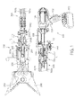
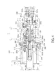
Fig. 1 is a cross sectional view showing the structure of an embodiment of a hydraulically-actuated device. -
Fig. 2 is a cross sectional view of a part ofFig. 1 in enlargement, showing the connected condition of a hydraulic joint structure between a hydraulic pressure generating unit and a hydraulic hose unit in the hydraulically-actuated device shown inFig. 1 . -
Fig. 3 is a cross sectional view showing the separated condition of the hydraulic joint structure shown inFig. 2 . -
Fig. 4 is a cross sectional view of a part ofFig. 1 in enlargement, showing the connected condition of an end tool unit and the hydraulic hose unit in the hydraulically-actuated device shown inFig. 1 . -
Fig. 5 is a cross sectional view showing the condition in which the hydraulic pressure generating unit and the end tool unit, which are shown inFig. 1 , are directly connected without using the hydraulic hose unit. -
Fig 6 is a cross sectional view for explaining the structure and the operation of a switch mechanism provided on an end member of the hydraulic hose unit on a side of the end tool unit shown inFig. 1 . -
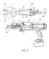
Fig. 7 is a cross sectional view showing the condition in which a single-acting end tool unit is connected with the hydraulic pressure generating unit through a hydraulic hose unit for a single-acting end tool unit. -
Fig. 8 is a cross sectional view showing the connected condition between the hydraulic hose unit for the single-acting end tool unit and the hydraulic pressure generating unit. -
Fig. 9 is a cross sectional view for explaining the structure and the operation of a modified switch mechanism provided on the end member of the hydraulic hose unit. - A hydraulic rescue tool as one embodiment of a hydraulically-actuated device will be described herebelow with reference to the accompanying drawings. Oil passages shown in the accompanying drawings are formed by drilling a solid material with a drill to form a plurality of linear holes, connecting crosswise the linear holes according to need, and/or closing the end portions of the holes with plugs according to need. Since the specific method for forming the oil passages can be readily understood by those skilled in the art only from the accompanying drawings, the method is not described in the specification. It goes without saying that the hydraulically-actuated device may be a hydraulic tool, such as a rebar cutter or a rebar bender, which has been widely used in the construction industry.
- As shown in
Figs. 1 and2 , the hydraulic rescue tool is composed of: a hydraulicpressure generating unit 100; a double-acting end tool unit 200 (which is also called "head unit") which is a spreader in this embodiment and which is driven by a hydraulic pressure generated by the hydraulicpressure generating unit 100; and a hydraulic hose unit (hereinafter referred to simply as "hose unit") 300 that connects the hydraulicpressure generating unit 100 and theend tool unit 200 with each other. The hydraulicpressure generating unit 100 and thehose unit 300 can be connected and separated to and from each other. In addition, theend tool unit 200 and thehose unit 300 can be connected and separated to and from each other. As described below, the hydraulicpressure generating unit 100 and the end tool unit can be directly connected with each other, without using thehose unit 300. -
Fig. 1 shows the condition in which the hydraulicpressure generating unit 100, theend tool unit 200 and thehose unit 300 are connected.Fig. 2 shows, in enlargement, a hydraulic joint structure C that connects the hydraulicpressure generating unit 100 and thehose unit 300 with each other.Fig. 3 shows the condition in which the hydraulicpressure generating unit 100 and thehose unit 300 are separated from each other. - As shown in
Fig. 1 , the hydraulicpressure generating unit 100 comprises a battery-powered electrohydraulic pump unit. The hydraulicpressure generating unit 100 includes agrip 102 provided with atrigger switch 104. When thetrigger switch 104 is pulled, an electric motor 106 (invisible inFig. 1 ) incorporated in the hydraulicpressure generating unit 100 operates to rotate apump 108, so that a pressurized hydraulic oil is fed to anoil discharge passage 110. Then, the hydraulic oil is returned to thepump 108 through anoil return passage 112. Abattery 103 as an electric power source for driving theelectric motor 106 is mounted on the lower end of thegrip 102. - The spreader as the
end tool unit 200 is a double-acting tool unit including a double-actinghydraulic cylinder 202. Namely, both the opening operation and closing operation of the spreader are performed hydraulically. When pressurized hydraulic oil fed from afirst oil passage 201a into afirst chamber 202a of thehydraulic cylinder 202, apiston 204 and arod 206 fixed to thepiston 204 are moved rightward inFig. 1 , so that a pair ofblades 208 of thespreader 200 are opened and that hydraulic oil in asecond chamber 202b is pushed out therefrom through asecond oil passage 201b. On the other hand, when pressurized hydraulic oil is fed into thesecond chamber 202b, thepiston 204 and therod 206 are moved leftward inFig. 1 , so that the pair ofblades 208 of thespreader 200 are closed, and that hydraulic oil in thefirst chamber 202a is pushed out therefrom. - The
hose unit 300 includes a pair ofhydraulic hoses hose unit 300 is connected with theend tool unit 200, thehydraulic hoses chambers - The hydraulic
pressure generating unit 100 and thehose unit 300 are connected by the hydraulic joint structure C. When the hydraulicpressure generating unit 100 and thehose unit 300 are connected with each other, theoil discharge passage 110 formed in a body of the hydraulicpressure generating unit 100 can be communicated with either one of the twohydraulic hoses hose unit 300, depending on the condition of a first switch mechanism SW1. The first switch mechanism SW1 is described herebelow. -
Fig. 2 shows the condition in which pressurized hydraulic oil is supplied from theoil discharge passage 110 of thepump 108 to the firsthydraulic hose 302a. A cylindricalspool valve element 120 is axially-slidably fitted in a spool valve hole formed in the body of the hydraulicpressure generating unit 100. Aninside space 122 extending axially in thespool valve element 120 defines the aforementionedoil return passage 112 for returning hydraulic oil to thepump 108. Thespool valve element 120 can be displaced by moving alever 121 by a finger of a user. Herebelow, the position of thespool valve element 120 shown inFig. 2 is referred to as "first position" in this specification. - In addition to the aforementioned
oil discharge passage 110, afirst oil passage 114 and asecond oil passage 116 are formed in the body of the hydraulicpressure generating unit 100. Theoil passages spool valve member 120 is inserted, which oil passages are spaced at equal intervals along the axial direction of the spool valve hole. An outer circumference of thespool valve element 120 is provided with threecircumferential grooves spool valve element 120. Thespool 120 has radial holes that connect the narrowercircumferential grooves inside space 122 serving as theoil return passage 112. The middlecircumferential groove 124 has such a large width that thegroove 124 can communicate adjacent two oil passages (110 and 114, or 110 and 116) with each other depending on the axial position of thespool valve element 120. - In the condition shown in
Fig. 2 in which thespool valve element 120 is positioned at the "first position", theoil discharge passage 110 is connected with thefirst oil passage 114 through thecircumferential groove 124 of thespool valve element 120. Thesecond oil passage 116 is connected with theinside space 122 of thespool valve element 120, i.e., theoil return passage 112, through thecircumferential groove 125 of thespool valve element 120 and the radial hole connected with thecircumferential groove 125. - When the
spool valve element 120, which has been positioned at the first position shown inFig. 2 , is displaced rightward inFig. 2 by a predetermined distance (i.e., the distance equal to an interval of theadjacent oil passages spool valve element 120 is placed at its "second position" (seeFig. 3 ), thecircumferential groove 123 of thespool valve element 120 is connected with thefirst oil passage 114, while theoil discharge passage 110 and thesecond oil passage 116 are connected with each other by the middle, widercircumferential groove 124.
Thus, at this time, theoil discharge passage 110 is connected with thesecond oil passage 116 through thecircumferential groove 124 of thespool 120; and thefirst oil passage 114 is connected with theinside space 122 of thespool 120, i.e., theoil return passage 112, through thecircumferential groove 123 of thespool 120 and the radial hole connected with thecircumferential groove 123. - Next, the hydraulic joint structure C for joining the hydraulic
pressure generating unit 100 and thehydraulic hose unit 300, is described with reference toFigs. 2 and3 . The hydraulic joint structure C includes a first joint portion C1 and a second joint portion C2 that are configured to be connectable and separable to and from each other. The first joint portion C1 is disposed on an end of the hydraulicpressure generating unit 100, and the second joint portion C2 is disposed on an end of thehydraulic hose unit 300 on the side of the hydraulicpressure generating unit 100. - The first joint portion C1 has an
outer cylinder 130 having generally a shape of a cylindrical sleeve and a mandrel 132 (i.e., a male member of the first joint portion C1) having a shape of a cylindrical column, which are parts of the body of the hydraulicpressure generating unit 100. The central axis of theouter cylinder 130 and a central axis of themandrel 132 coincide with each other. Aring member 134 having a shape of cylindrical sleeve is provided in a space, which has a shape of a circular ring and is defined between an inner circumference of theouter cylinder 130 and an outer circumference of themandrel 132. Thering member 134 is axially movable (slidable), with its inner circumference being guided by the outer circumference of themandrel 132 and its outer circumference being guided by the inner circumference of theouter cylinder 130. Thering member 134 is biased leftward in the drawings by aspring 136. As shown inFig. 3 , when the hydraulicpressure generating unit 100 and thehydraulic hose unit 300 are separated from each other, thering member 134 is positioned at an "oil passage-covering position" where thering member 134 prevents leakage of hydraulic oil from the oil passages. Astopper 138, which comprises a bolt in the illustrated example, is provided to properly position thering member 134 at the "oil passage-covering position". Thestopper 138 is received in anaxial groove 140 formed in the outer circumference of thering member 134. When thering member 134 is positioned at the "oil passage-covering position", thestopper 138 is in contact with astop surface 141 provided on an end portion of the ring member 134 (seeFig. 3 ). - The aforementioned
first oil passage 114 and thesecond oil passage 116 axially extend in thecylindrical mandrel 132, i.e., the male member. Thefirst oil passage 114 has anopen end portion 114a opening into the outer circumference of themandrel 132 at a first axial position of themandrel 132. Thesecond oil passage 116 has anopen end portion 116a opening into the outer circumference of themandrel 132 at a second axial position of the mandrel 132 (i.e., a position on the left side of the first axial position in the illustrated example). Acircumferential groove 142 is formed in the inner circumference of thering member 134. Thecircumferential groove 142 is configured such that, when thering member 134 is positioned at the "oil passage-covering position", thecircumferential groove 142 occupies such a position and has such a width that allow theopen end portion 114a and theopen end portion 116a to be communicated with each other. Ring-shapedseal members 144 are provided on the inner circumference of thering member 134, on both sides of thecircumferential groove 142. Thus, when thering member 134 is positioned at the "oil passage-covering position", leakage of hydraulic oil from theopen end portions seal members 144. In addition, even when an operator pulls thetrigger switch 104 by mistake, pressurized hydraulic oil having been fed from thepump 108 to theoil discharge passage 110 returns to theoil return passage 112 through thecircumferential groove 142, regardless of the position of thespool 120 for switching the oil passages. Thus, there is no possibility that the hydraulic oil leaks beyond theseal members 144, whereby thepump 108 can be prevented from being damaged. - The second joint portion C2, which is provided on the end of the
hydraulic hose unit 300 on the side of the hydraulicpressure generating unit 100, includes a generally cylindrical sleeve 304 (i.e., a female member of the second joint portion C2) having an axially-extending inside space formed in its central portion. In thesleeve 304, there are formed afirst oil passage 306 in communication with a firsthydraulic hose 302a, and asecond oil passage 308 in communication with a secondhydraulic hose 302b. Thefirst oil passage 306 has anopen end portion 306a opening into an inner circumference of thesleeve 304 at a first axial position of thesleeve 304. Thesecond oil passage 308 has anopen end portion 308a opening into the inner circumference of thesleeve 304 at a second axial position of the sleeve 304 (i.e., a position on the left side of the first axial position in the illustrated embodiment). Acircumferential groove 306b in communication with theopen end portion 306a is formed in the inner circumference of thesleeve 304 at the same axial position as that of theopen end portion 306a. In addition, acircumferential groove 308b in communication with theopen end portion 308a is formed in the inner circumference of thesleeve 304 at the same axial position as that of theopen end portion 308b. The axial distance between thecircumferential groove 306a and thecircumferential groove 308b is the same as the axial distance between theopen end portion 114a and theopen end portion 116a, which are provided in themandrel 132 of the first joint portion C1. - The diameter of the inner circumference of the
sleeve 304 is slightly larger than the diameter of themandrel 132 of the first joint portion C1 (like "loose fit"), so that themandrel 132 can be smoothly inserted into thesleeve 304. Arod member 312 having a shape of a cylindrical column is disposed in thesleeve 304. Therod member 312 is axially movable (slidable) in thesleeve 304. Therod member 312 is biased rightward in the drawings by aspring 314. As shown inFig. 3 , when the hydraulicpressure generating unit 100 and thehydraulic hose unit 300 are separated from each other, therod member 312 is positioned at an "oil passage-covering position" where therod member 312 prevents leakage of hydraulic oil from theoil passages stopper 316, which comprises a step formed in the inner circumference of thecylindrical sleeve 304 in the illustrated embodiment, is provided to properly position therod member 312 at the "oil passage-covering position". When therod member 312 is positioned at the "oil passage-covering position", thestopper 316 is in contact with astop surface 318, which comprises a surface of an enlarged diameter portion provided at an end portion of therod member 312. When therod member 312 is positioned at the "oil passage-covering position", therod member 312 closes theopen end portion 306a of thefirst oil passage 306 and thecircumferential groove 306b in communication therewith, as well as theopen end portion 308a of thesecond oil passage 308 and thecircumferential groove 308b in communication therewith. - Three ring-shaped
seal members sleeve 304. Theopen end portion 306a of the first oil passage 306 (and thecircumferential groove 306b) opens into the inner circumference of thesleeve 304 at the first axial position of thesleeve 304 between theseal member 322 and theseal member 324. Theopen end portion 308a of the second oil passage 308 (and thecircumferential groove 308b) opens into the inner circumference of thesleeve 304 at the second axial position of thesleeve 304 between theseal member 320 and theseal member 322. When therod member 312 is positioned at the "oil passage-covering position", leakage of hydraulic oil in thefirst oil passage 306 and thesecond oil passage 308 to the outside can be prevented by theseal members - Upon connection of the second joint portion C2 with the first joint portion C1, the condition shown in
Fig. 3 will be changed into the condition shown inFig. 2 .
Namely, the mandrel 132 (i.e., male member) of the first joint portion C1 is inserted into the cylindrical inside space of the sleeve 304 (i.e., female member) of the second joint portion C2, so that themandrel 132 pushes therod member 312 leftward inFig. 2 , while compressing thespring 314. In addition, the end surface of thesleeve 304 pushes thering member 134 rightward inFig. 2 , while compressing thespring 136. The positions of thering member 134 and therod member 312 in this condition are referred to as "retracted positions". - At this time, the first axial position of the outer circumference of the
mandrel 132 and the first axial position of the inner circumference of thesleeve 304 are opposed to each other, and the second axial position of the outer circumference of themandrel 132 and the second axial position of the inner circumference of thesleeve 304 are opposed to each other. At a first axial position of the hydraulic joint structure C, theopen end portion 114a of thefirst oil passage 114 of the hydraulicpressure generating unit 100 and theopen end portion 306a of thefirst oil passage 306 of thehydraulic hose unit 300 are connected via thecircumferential groove 306b to form a first connection. In addition, at a second axial position of the hydraulic joint structure C, theopen end portion 116a of thesecond oil passage 116 of the hydraulicpressure generating unit 100 and theopen end portion 308a of thesecond oil passage 308 of thehydraulic hose unit 300 are connected via thecircumferential groove 308b to form a second connection. Further, at this time, theseal members mandrel 132 and the inner circumference of thesleeve 304. Theseal members open end portion 114a, and theopen end portion 306a and thecircumferential groove 306b to seal the aforementioned first connection. Theseal members open end portion 116a, and theopen end portion 308a and thecircumferential groove 308b to seal the aforementioned second connection. Due to the provision of thecircumferential grooves open end portion 114a (116a) is opposed to theopen end portion 306a (308a). Thus, the connection operation can be significantly facilitated. Such a circumferential groove may be provided at a position of theopen end portion 114a (116a) of the outer circumference of themandrel 132, or may be provided in both the outer circumference of themandrel 132 and the inner circumference of thesleeve 304. - A lock mechanism is provided for maintaining the connected condition of the second joint portion C2 and the first joint portion C1. The lock mechanism is described below. There is provided a
lock ring 150 that is axially slidable along the outer circumference of theouter cylinder 130 of the first joint portion C1. A chamferedportion 152 is formed on an end portion of thelock ring 150. Theouter cylinder 130 is provided with a plurality of (e.g., six to ten) radial holes, which pass radially through the outer cylinder 130 (in the thickness direction), and which are evenly distributed along the circumferential direction. Alock ball 154 of an elliptic cross section is held in each radial hole such that thelock ball 154 is movable in the radial direction ofouter cylinder 130. Anannular recess 330 adapted to receive thelock balls 154 is formed in the outer circumference of thesleeve 304 of the second joint portion C2. A radius of curvature of the surface of theannular recess 330 is relatively large, and thus theannular recess 330 has the surface of a relatively shallow slope. Thelock ring 150 is biased toward a "lock position (seeFig. 2 )", which is on the left side in the drawings, by aspring 158 disposed between thelock ring 150 and theouter cylinder 130. - In the condition shown in
Fig. 3 , since thering member 134 prevents thelock balls 154 from moving radially inward, thelock ring 150 cannot move leftward inFig. 3 . As shown inFig. 2 , when the second joint portion C2 is connected with the first joint portion C1, the axial position of eachlock ball 154 and the axial position of eachannular recess 330 coincides with each other, whereby thelock ball 154 can move radially inward by a distance corresponding to the depth of theannular recess 330. Then, while thelock ring 150 is moved leftward in the drawings by a force of thespring 158, the chamferedportion 152 of thelock ring 150 pushes thelock balls 154 radially inward, and thelock ring 150 overrides thelock balls 154. In order to stop thelock ring 150 at a predetermined axial position ("lock position"), astopper ring 156 is provided on the outer circumference of theouter cylinder 130. In the condition shown inFig. 2 , since thelock ring 150 prevents thelock balls 154 from moving radially outward, the connection between the second joint portion C2 and the first joint portion C1 is securely maintained. The connected condition between the second joint portion C2 and the first joint portion C1 can be released in the following manner. Namely, an operator moves thelock ring 150 rightward in the drawings against thespring 158 to allow thelock balls 154 to move radially outward. Under this condition, when the second joint portion C2 is drawn from the first joint portion C1, thelock balls 154 are moved radially outward while being guided by the surface of a relatively shallow slope of theannular recess 330. - Heretofore, the hydraulic joint structure C between the hydraulic
pressure generating unit 100 and the end of thehose unit 300 on the side of the hydraulicpressure generating unit 100 has been described. A hydraulic joint structure C' between the spreader as theend tool unit 200 and the end of thehose unit 300 on the side of theend tool unit 200 has the same structure. This is apparent fromFig. 4 showing the hydraulic joint structure C' in enlargement. InFig. 4 showing the hydraulic joint structure C', the constituent members of the hydraulic joint structure C' corresponding to the constituent members of the hydraulic joint structure C are indicated by the same reference numbers but with the dash symbol ('). The fact that the hydraulic joint structures C and C' have the same structure means that the hydraulicpressure generating unit 100 can be directly connected with theend tool unit 200. Such a manner of use is also intended.Fig. 5 shows a condition in which the hydraulicpressure generating unit 100 is directly connected with theend tool unit 200. - As shown in
Figs. 1 and6 , an end piece (end member) of thehose unit 300 constituting the hydraulic joint structure C' on the side of theend tool unit 200 is provided with a switch mechanism SW2 between the joint portion C1' and the ends of thehydraulic hoses end tool unit 200, under the condition in which the aforementioned switch mechanism SW1 is adjusted such that pressurized hydraulic oil is supplied to thehydraulic hose 302a and that return oil flows through thehydraulic hose 302b. - The structure and operation of the switch mechanism SW2 are described with reference particularly to
Fig. 6 . The switch mechanism SW2 includes aslide valve 310 having, in its outer circumference,circumferential grooves slide valve 310 is slidable in an up and down direction inFig. 6 , and can take a first position shown inFig. 6(a) , a neutral position shown inFig. 6(b) and a second position shown inFig. 6(c) . The switch mechanism SW2 is provided with afirst oil passage 401 in communication with thehydraulic hose 302b, asecond oil passage 402 in communication with thehydraulic hose 302a, and athird oil passage 403 disposed between thefirst oil passage 401 and thesecond oil passage 402 in parallel with thefirst oil passage 401 and thesecond oil passage 402. Thefirst oil passage 401 and thesecond oil passage 402 are connected via afourth oil passage 404. Hydraulic oil can freely flow in thefourth oil passage 404 upward and downward inFig. 6 . Thesecond oil passage 402 and thethird oil passage 403 are connected via afifth oil passage 405. Thefifth oil passage 405 is provided with acheck valve 406, whereby hydraulic oil can flow in thefifth oil passage 405 only in the upward direction inFig. 6 . Thesecond oil passage 402 is provided with acheck valve 407, whereby hydraulic oil cannot flow leftward inFig. 6 through the check valve 407 (hydraulic oil is allowed to flow rightward inFig. 6 through the check valve 407). Thus, when pressurized hydraulic oil flows from thehydraulic hose 302a into thesecond oil passage 402, the hydraulic oil flows into thefifth oil passage 405 to flow therethrough in the upward direction inFig. 6 . - Thus, when the
slide valve 310 is positioned at the first position shown inFig. 6(a) , pressurized hydraulic oil, having flown from thehydraulic hose 302a to thesecond oil passage 402, flows through thefifth oil passage 405 and thecircumferential groove 315 into the oil passage 114'. On the other hand, return oil in the oil passage 116' flows through thecircumferential groove 311 and thefirst oil passage 401 into thehydraulic hose 302b. - When the
slide valve 310 is positioned at the neutral position shown inFig. 6(b) , pressurized hydraulic oil, having flown from thehydraulic hose 302a into thesecond oil passage 402, flows through thefifth oil passage 405 and thecircumferential groove 315, but cannot go farther. Also, hydraulic oil in the oil passages 114' and 116' cannot reach thehydraulic hose 302b. - When the
slide valve 310 is positioned at the second position shown inFig. 6(c) , pressurized hydraulic oil, having flown from thehydraulic hose 302a into thesecond oil passage 402, flows through thefifth oil passage 405, thethird oil passage 403 and thecircumferential groove 315 into the oil passage 116'. On the other hand, return oil in the oil passage 114' flows through thecircumferential groove 313, thesecond oil passage 402, thefourth oil passage 404 and thefirst oil passage 401 into thehydraulic hose 302b. - Although the description has been made for the case in which the
end tool unit 200 is a double-acting tool unit, a single-acting tool unit can be connected with the hydraulicpressure generating unit 100.Figs. 7 and8 show an embodiment in which a single-actingend tool unit 500 is connected with the above-described hydraulicpressure generating unit 100 via ahydraulic hose unit 600 for a single-acting end tool unit. The illustrated single-actingend tool unit 500 is a shear cutter. Theend tool unit 500 includes a single-actinghydraulic cylinder 501. When pressurized hydraulic oil is supplied to achamber 502 on one side of thehydraulic cylinder 501, apiston 503 is moved leftward in the drawings, so that a pair ofblades 504 are closed. When the hydraulic pressure in thechamber 502 is released, areturn spring 505 pushes back thepiston 503, so that the pair ofblades 504 are opened. - The
hydraulic hose unit 600 includes a joint portion Cs for a single-acting use that can be connected with the joint portion C1 disposed on the hydraulicpressure generating unit 100. The joint portion Cs for a single-acting use differs from the aforementioned joint portion C2 in the following points. Asecond oil passage 308" in communication with theopen end portion 308a is merged with thefirst oil passage 306. Namely, both thefirst oil passage 306 and thesecond oil passage 308" are connected with the singlehydraulic hose 302a of the hydraulic hose unit 600 (Note that, in the above-described joint portion C2, thesecond oil passage 308 is connected with thehydraulic hose 302b). Thesecond oil passage 308" is provided with acheck valve 601. Thecheck valve 601 allows hydraulic oil to flow from theopen end portion 308a toward thehydraulic hose 302a through thesecond oil passage 308", but prevents hydraulic oil from flowing from thehydraulic hose 302a toward theopen end portion 308a through thesecond oil passage 308" to return to the first joint portion C1. -
Figs. 7 and8 show the non-operated condition. Pressurized hydraulic oil having flown from theoil passage 116 in the mandrel 132 (i.e., male member) into thesecond oil passage 308" pushes the ball of thecheck valve 601 away to reach the root portion of the hydraulic hose 302, but the hydraulic oil returns to the pump through thefirst oil passage 306 and theoil passage 114. Thus, no pressurized hydraulic oil is supplied to the single-actingend tool unit 500. When thespool valve 120 is displaced leftward in the drawings from this condition (i.e., thespool valve 120 is moved from the "second position" to the "first position"), hydraulic oil flows from theoil passage 114 in the mandrel 132 (i.e., male member) to reach the root portion of thehydraulic hose 302a through thefirst oil passage 306, and also attempt to flow into thesecond oil passage 308". However, since the flow is disturbed by thecheck valve 601 disposed in thesecond oil passage 308", pressurized hydraulic oil is supplied to theend tool unit 500 through thehydraulic hose 302a of thehydraulic hose unit 600. -
Fig. 9 shows a switch mechanism SW2' which is one modification of the switch mechanism SW2 shown inFig. 6 , and which can be replaced with the switch mechanism SW2 shown inFig. 6 . The switch mechanism SW2' ofFig. 9 functionally differs from the switch mechanism SW2 shown inFig. 6 in that, at a neutral position shown inFig. 9(b) , pressurized hydraulic oil is not blocked by a valve element, but is returned to an oil return passage. The structure of the switch mechanism SW2' ofFig. 9 is described below. The constituent members shown inFig. 9 which are identical or similar to the constituent members shown inFig. 6 are indicated by the same reference numbers but with the dash symbol (') or the two-dash symbol ("). - The switch mechanism SW2' includes a slide valve 310' having, in its outer circumference, circumferential grooves 311', 315' and 313'. The slide valve 310' is slidable in the up and down direction in
Fig. 9 , and can take a first position shown inFig. 9(a) , a neutral position shown inFig. 9(b) and a second position shown inFig. 9(c) . Acentral oil passage 410 is provided in the slide valve 310' to extend in the axial direction. Both ends of thecentral oil passage 410 open into bottoms of the circumferential grooves 311' and 313', so as to connect the circumferential grooves 311' and 313' with each other. The switch mechanism SW2' is provided with a first oil passage 401' in communication with thehydraulic hose 302b, a second oil passage 402' in communication with thehydraulic hose 302a, and a third oil passage 403' disposed between the first oil passage 401' and the second oil passage 402' in parallel with the first oil passage 401' and the second oil passage 402'. The first oil passage 401' and the third oil passage 403' are connected via afourth oil passage 411. Since acheck valve 414 is disposed on a lower end portion of thefourth oil passage 411, hydraulic oil can flow from the first oil passage 401' into the third oil passage 403' but cannot flow reversely. Since the second oil passage 402' is provided with acheck valve 413, hydraulic oil can flow from the left to the right inFig. 9 through thecheck valve 413 but cannot flow reversely. The switch mechanism SW2' shown inFig. 9 is designed on the assumption that it is used under the condition that the switch mechanism SW1 is set such that pressurized hydraulic oil is supplied to thehydraulic hose 302b (i.e., thehydraulic hose 302a is used as a return line). - When the slide valve 310' is positioned at the first position shown in
Fig. 9(a) , pressurized hydraulic oil, having flown from thehydraulic hose 302b into thefirst oil passage 401, flows through thefourth oil passage 411 into the third oil passage 403', and further flows through the circumferential groove 315' of the slide valve 310' into theoil passage 116". On the other hand, return oil in theoil passage 114" flows through the circumferential groove 313' and thesecond oil passage 402 into thehydraulic hose 302a. - When the slide valve 310' is positioned at the neutral position shown in
Fig. 9(b) , pressurized hydraulic oil, having flown from thehydraulic hose 302b into thefirst oil passage 401, flows sequentially through the circumferential groove 315', thecentral oil passage 410 and the circumferential groove 313' of the slide valve 310' into the second oil passage 402', and further flows into thehydraulic hose 302a. - When the slide valve 310' is positioned at the second position shown in
Fig. 9(c) , pressurized hydraulic oil, having flown from thehydraulic hose 302b into the first oil passage 401', flows sequentially through thefourth oil passage 411, the third oil passage 403' and the circumferential groove 312' of the slide valve 310' into theoil passage 114". On the other hand, return oil in theoil passage 116" flows sequentially through the circumferential groove 311', thecentral oil passage 410 and the circumferential groove 313' of the slide valve 310' into the second oil passage 402', and further flows into thehydraulic hose 302a. - Differently from the switch mechanism SW2 of
Fig. 6 , in the switch mechanism SW2' ofFig. 9 , pressurized hydraulic oil is not blocked by the slide valve 310' positioned in its neutral position. This reduces the load on thepump 308, and the slide valve 310' can be smoothly moved from the neutral position to the first position or to the second position. -
- C, C' Hydraulic joint structure
- C1, C1' First joint portion
- C2, C2' Second joint portion
- Cs Joint portion for single-acting use
- 100 Hydraulic pressure generating unit
- 114 First oil passage of first joint portion
- 114a First open end portion
- 116 Second oil passage of second joint portion
- 116a Second open end portion
- 132 Male member (Mandrel)
- 134 Ring member
- 142 Communication groove in inner circumference of ring member
- 200 End tool unit
- 208 Tool (Blade)
- 300 Hydraulic hose unit
- 304 Female member (Sleeve)
- 306 First oil passage of second joint portion
- 306b Circumferential groove
- 308 Second oil passage of second joint portion
- 308a Second open end portion
- 308b Circumferential groove
- 312 Cylindrical member (Rod member)
- 500 End tool unit for single-acting use
- 600 Hydraulic hose unit for end tool unit for single-acting use
Claims (11)
- A first joint portion (C1, C1') which is capable to be releasably connected with a second joint portion (C2, C2') in order to constitute a hydraulic joint structure (C, C'), wherein:the first joint portion (C1, C1') has a first oil passage (114) and a second oil passage (116);the first joint portion (C1, C1') has a cylindrical male member (132);the first oil passage (114; 114') of the first joint portion (C1, C1') extends in the male member (132) of the first joint portion (C1, C1') and has a first open end portion (114a) opening into an outer circumference of the male member (132) at a first axial position of the male member (132);the second oil passage (116; 116') of the first joint portion (C1, C1') extends in the male member (132) of the first joint portion (C1, C1') and has a second open end portion (116a) opening into an outer circumference of the male member (132) at a second axial position of the male member (132),said first joint portion (C1, C1') further comprising a ring member (134), which has a cylindrical hole into which the male member (132) of the first joint portion (C1, C1') is inserted and which is movable between an oil passage-covering position and a retracted position along an axial direction of the male member (132),wherein:the ring member (134) is biased toward the oil passage-covering position by a spring (136);the ring member (134) has an inner circumference provided therein with a communication groove (142); andwhen the ring member (134) is positioned at the oil passage-covering position, the first open end portion of the first oil passage (114) of the male member (132) and the second open end portion of the second oil passage (116) of the male member (132) are connected via the communication groove (142).
- A second joint portion (C2, C2') which is capable to be releasably connected with a first joint portion (C1, C1') in order to constitute a hydraulic joint structure (C, C'), wherein:the second joint portion (C2, C2') has a first oil passage (306) and a second oil passage (308);the second joint portion (C2, C2') has a female member (304) with a cylindrical hole;the first oil passage (306) of the second joint portion (C2, C2') extends in the female member (304) of the second joint portion (C2, C2') and has a first open end portion (306a) opening into an inner circumference of the female member (304) at a first axial position of the female member (304); andthe second oil passage (308) of the second joint portion (C2, C2') extends in the female member (304) of the second joint portion (C2, C2') and has a second open end portion (308a) opening into an inner circumference of the female member (304) at a second axial position of the female member (304);said second joint portion (C2, C2') further comprising a cylindrical member (312) provided in the cylindrical hole of the female member (304) of the second joint portion (C2, C2') so as to be axially movable between an oil passage-covering position and a retracted position,wherein:the cylindrical member (312) is biased toward the oil passage-covering position by a spring (314);when the cylindrical member (312) is positioned at the oil passage-covering position, the cylindrical member (312) closes the first open end portion (306a) of the first oil passage (306) of the female member (304) and the second open end portion (308a) of the second oil passage (308) of the female member (304).
- A hydraulic joint structure comprising a first joint portion (C1, C1') according to claim 1 and a second joint portion (C2, C2') according to claim 2 releasably connected with the first joint portion (C1, C1'), wherein:the male member (132) of the first joint portion (C1, C1') is inserted into the cylindrical hole of the female member (304);when the male member (132) is inserted into the cylindrical hole of the female member (304) to connect the first joint portion (C1, C1') and the second joint portion (C2, C2') with each other, the first open end portion (114a) of the first oil passage (114) of the male member (132) and the first open end portion (306a) of the first oil passage (306) of the female member (304) are connected at a first axial position of said hydraulic joint structure (C, C') corresponding to the first axial position of the male member (132) and the female member (304) to form a first connection, and the second open end portion (116a) of the second oil passage (116) of the male member (132) and the second open end portion (308a) of the second oil passage (308) of the female member (304) are connected at a second axial position of said hydraulic joint structure (C, C') corresponding to the second axial position of the male member (132) and the female member (304) to form a second connection;wherein:when the first joint portion (C1, C1') and the second joint portion (C2, C2') are separated from one another, the ring member (134) is positioned at the oil passage-covering position to connect via the communication groove the first open end portion (114a) of the first oil passage (114) of the male member (132) and the second open end portion (116a) of the second oil passage (116) of the male member (132); andwhen the first joint portion (C1, C1') and the second joint portion (C2, C2') are connected with each other, the second joint portion (C2, C2') pushes the ring member (134) into the retracted position against a force of the spring (136).
- The hydraulic joint structure (C, C') according to claim 3 wherein:when the first joint portion (C1, C1') and the second joint portion (C2, C2') are separated from one another, the cylindrical member (312) is positioned at the oil passage-covering position of the cylindrical member (312) to close the first open end portion (306a) of the first oil passage (306) of the female member (304) and the second open end portion (308a) of the second oil passage (308) of the female member (304); andwhen the first joint portion (C1, C1') and the second joint portion (C2, C2') are connected with each other, the male member (132) pushes the cylindrical member (312) into the retracted position of the cylindrical member (312) against a force of the spring (314).
- A hydraulic joint structure comprising a first joint portion (C1, C1') according to claim 1 and a second joint portion (C2, C2') according to claim 2 releasable connected with the first joint portion (C1, C1'), wherein:the male member (132) of the first joint portion (C1, C1') is inserted into the cylindrical hole of the female member (304);when the male member (132) is inserted into the cylindrical hole of the female member (304) to connect the first joint portion (C1, C1') and the second joint portion (C2, C2') with each other, the first open end portion (114a) of the first oil passage (114) of the male member (132) and the first open end portion (306a) of the first oil passage (306) of the female member (304) are connected at a first axial position of said hydraulic joint structure (C, C') corresponding to the first axial position of the male member (132) and the female member (304) to form a first connection, and the second open end portion (116a) of the second oil passage (116) of the male member (132) and the second open end portion (308a) of the second oil passage (308) of the female member (304) are connected at a second axial position of said hydraulic joint structure (C, C') corresponding to the second axial position of the male member (132) and the female member (304) to form a second connection;wherein:when the first joint portion (C1, C1') and the second joint portion (C2, C2') are separated from one another, the cylindrical member (312) is positioned at the oil passage-covering position of the cylindrical member (312) to close the first open end portion (306a) of the first oil passage (306) of the female member (304) and the second open end portion (308a) of the second oil passage (308) of the female member (304); andwhen the first joint portion (C1, C1') and the second joint portion (C2, C2') are connected with each other, the male member (132) pushes the cylindrical member (312) into the retracted position of the cylindrical member (312) against a force of the spring (314).
- The hydraulic joint structure (C, C') according to any one of claims 3 to 5 wherein:the first open end portion (114a) of the male member (132) and the first open end portion (306a) of the female member (304) are connected through a first circumferential groove (306b), the first circumferential groove (306b) is one extending in the outer circumference of the male member (132) in a circumferential direction at the first axial position of the male member (132), or one extending in the inner circumference of the male member (132) in a circumferential direction at the first axial position of the female member (304); andthe second open end portion (116a) of the male member (132) and the second open end portion (308a) of the female member (304) are connected through a second circumferential groove (308b), the second circumferential groove (308b) is one extending in the outer circumference of the male member (132) in a circumferential direction at the second axial position of the male member (132), or one extending in the inner circumference of the female member (304) in a circumferential direction at the second axial position of the female member (304).
- A hydraulic pressure generating unit (100) comprising:a hydraulic pump (108);an oil discharge passage (110) and an oil return passage (112) connected with the hydraulic pump (108);a first joint portion (C1') according to claim 1;a switch mechanism (SW2) configured to switch between a first condition in which the oil discharge passage (110) is connected with the first oil passage (114') of the first joint portion (C1') while the oil return passage (112) is connected with the second oil passage (116'), and a second condition in which the oil discharge passage (110) is connected with the second oil passage (116') of the first joint portion (C1') while the oil return passage (112) is connected with the first oil passage (114').
- An end tool unit (200) comprising:a double-acting, hydraulic cylinder (202) having a first chamber (202a) and a second chamber (202b);a tool (208) that operates in an interlocked manner with an operation of the hydraulic cylinder (202); andthe second joint portion (C2') according to claim 2,wherein the first oil passage (306) of the second joint portion (C2') is connected with the first chamber (202a) of the hydraulic cylinder (202) while the second oil passage (308) of the second joint portion (C2') is connected with the second chamber (202b) of the hydraulic cylinder (202).
- A hydraulic hose unit (300) comprising:a first hydraulic hose (302a) and a second hydraulic hose (302b);the first joint portion (C1, C1') according to claim 1, which is connected with a first end of the first hydraulic hose (302a) and with a first end of the second hydraulic hose (302b); andthe second joint portion (C2, C2') according to claim 2, which is connected with a second end of the first hydraulic hose (302a) and with a second end of the second hydraulic hose (302b).
- A hydraulically-actuated device comprising:the hydraulic pressure generating unit (100) according to claim 7; andthe end tool unit (200) according to claim 8,wherein the joint structure (C, C') referred to in claims 1 and 2 is that defined in claim 4,wherein the first joint portion (C1, C1') of the hydraulic pressure generating unit (100) and the second joint portion (C2, C2') of the end tool unit (200) are connected with each other to form a hydraulic joint structure (C, C') according to claim 4.
- A hydraulically-actuated device comprising:the hydraulic pressure generating unit (100) according to claim 7;the end tool unit (200) according to claim 8; andthe hose unit (300) according to claim 9,wherein the joint structure (C, C') referred to in claims 1 and 2 is that defined in claim 4,wherein the first joint portion (C1, C1') of the hydraulic pressure generating unit (100) and the second joint portion (C2, C2') of the hose unit (300) are connected with each other to form a hydraulic joint structure (C, C') according to claim 4, and 04.12.2015wherein the second joint portion (C2, C2') of the end tool unit (200) and the first joint portion (C1, C1') of the hose unit (300) are connected with each other to form a hydraulic joint structure (C, C') according to claim 4.
Applications Claiming Priority (2)
| Application Number | Priority Date | Filing Date | Title |
|---|---|---|---|
| JP2011092284A JP5738661B2 (en) | 2011-04-18 | 2011-04-18 | Hydraulic joint structure, hydraulic actuator equipped with hydraulic joint structure, joint part constituting hydraulic joint structure, hydraulic generation unit equipped with joint part, tip tool unit, hydraulic hose unit |
| PCT/JP2012/060282 WO2012144465A1 (en) | 2011-04-18 | 2012-04-16 | Hydraulic joint structure, hydraulic operation device with hydraulic joint structure, joint portion constituting hydraulic joint structure, hydraulic pressure generation unit with joint portion, front end tool unit with joint portion, and hydraulic hose unit with joint portion |
Publications (3)
| Publication Number | Publication Date |
|---|---|
| EP2700863A1 EP2700863A1 (en) | 2014-02-26 |
| EP2700863A4 EP2700863A4 (en) | 2015-06-03 |
| EP2700863B1 true EP2700863B1 (en) | 2016-10-05 |
Family
ID=47041571
Family Applications (1)
| Application Number | Title | Priority Date | Filing Date |
|---|---|---|---|
| EP12774904.2A Active EP2700863B1 (en) | 2011-04-18 | 2012-04-16 | Hydraulic joint structure, hydraulic operation device with hydraulic joint structure, joint portion constituting hydraulic joint structure, hydraulic pressure generation unit with joint portion, front end tool unit with joint portion, and hydraulic hose unit with joint portion |
Country Status (6)
| Country | Link |
|---|---|
| US (1) | US9441775B2 (en) |
| EP (1) | EP2700863B1 (en) |
| JP (1) | JP5738661B2 (en) |
| KR (1) | KR101789859B1 (en) |
| CN (1) | CN104379981B (en) |
| WO (1) | WO2012144465A1 (en) |
Cited By (1)
| Publication number | Priority date | Publication date | Assignee | Title |
|---|---|---|---|---|
| US10293192B2 (en) | 2015-01-26 | 2019-05-21 | Lukas Hydraulik Gmbh | Hydraulic implement |
Families Citing this family (11)
| Publication number | Priority date | Publication date | Assignee | Title |
|---|---|---|---|---|
| JP6173872B2 (en) * | 2013-10-17 | 2017-08-02 | 株式会社オグラ | Double acting hydraulic actuator |
| JP6173871B2 (en) * | 2013-10-17 | 2017-08-02 | 株式会社オグラ | Hydraulic actuator |
| JP6469557B2 (en) * | 2015-10-05 | 2019-02-13 | 株式会社オグラ | Hydraulic actuator |
| ITUA20161807A1 (en) * | 2016-03-18 | 2017-09-18 | Cembre Spa | HYDRAULIC COMPRESSION OR CUTTING TOOL |
| WO2018127975A1 (en) * | 2017-01-06 | 2018-07-12 | 株式会社オグラ | Hydraulic working device and torque transmission coupling |
| AT520046B1 (en) | 2017-06-12 | 2022-10-15 | Weber Hydraulik Gmbh | Hydraulic unit for hydraulic rescue tools and rescue tools equipped therewith |
| JP6842570B2 (en) * | 2018-01-15 | 2021-03-17 | 株式会社オグラ | Hydraulic actuator |
| JP7307169B2 (en) * | 2018-11-26 | 2023-07-11 | ルーカス ヒュードラウリク ゲーエムベーハー | portable portable tools |
| CN110102623A (en) * | 2019-04-17 | 2019-08-09 | 上海发那科机器人有限公司 | A kind of water oil circuit automation fast switching system of hot forming water cooling mold |
| WO2021095098A1 (en) * | 2019-11-11 | 2021-05-20 | 株式会社オグラ | Hydraulic actuation device |
| EP4056028A1 (en) * | 2021-03-08 | 2022-09-14 | Dubuis et Cie | Hydraulic device with movable blades |
Family Cites Families (10)
| Publication number | Priority date | Publication date | Assignee | Title |
|---|---|---|---|---|
| US4285364A (en) * | 1978-12-04 | 1981-08-25 | Clayton Dewandre Co. Ltd. | Hose coupling |
| JPS62272919A (en) * | 1986-05-22 | 1987-11-27 | 深水 清則 | Cutter |
| US5482082A (en) * | 1994-06-22 | 1996-01-09 | Cooper Cameron Corporation | Multi-passage fluid coupling and metal seal therefor |
| US6619319B1 (en) * | 1998-07-29 | 2003-09-16 | Woods Equipment Company | Multi-line fluid connector |
| JP2002371585A (en) * | 2001-06-18 | 2002-12-26 | Nikken Corp | Swing device and hydraulic circuit of clamshell bucket |
| JP2005201285A (en) * | 2002-02-01 | 2005-07-28 | Ogura:Kk | Hydraulic actuation device |
| JP3977155B2 (en) | 2002-06-14 | 2007-09-19 | 株式会社オグラ | Hydraulic actuator |
| US7147003B2 (en) * | 2003-06-03 | 2006-12-12 | Parker-Hannifin | Coaxial quick disconnect coupling |
| JP2005114150A (en) * | 2003-09-19 | 2005-04-28 | Myotoku Ltd | Multitubular piping device, and multitubular piping attachment manifold |
| CN201133532Y (en) * | 2007-11-29 | 2008-10-15 | 湖北三江航天万山特种车辆有限公司 | Multichannel heavy pressure swiveling joint |
-
2011
- 2011-04-18 JP JP2011092284A patent/JP5738661B2/en active Active
-
2012
- 2012-04-16 EP EP12774904.2A patent/EP2700863B1/en active Active
- 2012-04-16 CN CN201280019332.3A patent/CN104379981B/en active Active
- 2012-04-16 WO PCT/JP2012/060282 patent/WO2012144465A1/en active Application Filing
- 2012-04-16 KR KR1020137029156A patent/KR101789859B1/en active IP Right Grant
- 2012-04-16 US US14/112,402 patent/US9441775B2/en active Active
Cited By (2)
| Publication number | Priority date | Publication date | Assignee | Title |
|---|---|---|---|---|
| US10293192B2 (en) | 2015-01-26 | 2019-05-21 | Lukas Hydraulik Gmbh | Hydraulic implement |
| US10589135B2 (en) | 2015-01-26 | 2020-03-17 | Lukas Hydraulik Gmbh | Hydraulic implement |
Also Published As
| Publication number | Publication date |
|---|---|
| CN104379981B (en) | 2016-09-28 |
| KR20140012741A (en) | 2014-02-03 |
| EP2700863A4 (en) | 2015-06-03 |
| EP2700863A1 (en) | 2014-02-26 |
| US9441775B2 (en) | 2016-09-13 |
| JP2012225397A (en) | 2012-11-15 |
| WO2012144465A1 (en) | 2012-10-26 |
| KR101789859B1 (en) | 2017-10-25 |
| JP5738661B2 (en) | 2015-06-24 |
| CN104379981A (en) | 2015-02-25 |
| US20140034149A1 (en) | 2014-02-06 |
Similar Documents
| Publication | Publication Date | Title |
|---|---|---|
| EP2700863B1 (en) | Hydraulic joint structure, hydraulic operation device with hydraulic joint structure, joint portion constituting hydraulic joint structure, hydraulic pressure generation unit with joint portion, front end tool unit with joint portion, and hydraulic hose unit with joint portion | |
| CN108825132B (en) | Dual-rod directional drilling system | |
| CN101379337A (en) | Multiconnector for a conduit | |
| EP2137448B1 (en) | Coaxial coupling with by-pass valve and coupling mechanism with bayonette form | |
| EP2431646B1 (en) | Coaxial quick coupling | |
| US9810360B2 (en) | Quick coupling for connecting during fluid flow in a hydraulic circuit | |
| WO2006044763A2 (en) | Subsea junction plate assembly running tool and method of installation | |
| CN102059686B (en) | Electrohydraulic pressing device having removable hose assembly | |
| US7484768B2 (en) | Connector | |
| AU2013407734C1 (en) | Hydraulic tool | |
| AU2004319611B2 (en) | Coaxial coupling | |
| MY172384A (en) | Arm assembly | |
| RU2495317C2 (en) | Retractable coupling sleeve for liquids under pressure | |
| EP2352899B1 (en) | Downhole actuator | |
| CN107250634B (en) | Safety valve for hydraulic or pneumatic tools | |
| US9216501B2 (en) | Electro-hydraulic pressing device | |
| US6341803B1 (en) | Coupling device | |
| US20070261403A1 (en) | Pressure shuttle | |
| JP5079056B2 (en) | Joint with valve and joint device | |
| JP2005164038A (en) | Flat-surface quick coupling tube extending between pressurized fluid using device and fluid feeding means | |
| KR101582440B1 (en) | Universal coupler for air device and air tool | |
| IT201800006430A1 (en) | QUICK CONNECTION KIT FOR IRRIGATION HOSES | |
| JP2010266071A5 (en) | ||
| EP3244115B1 (en) | Kit comprising a plurality of male couplings with an integrated shunt system for achieving a shunt function on the movable side of a multi-coupling device and multi-coupling device comprising said kit | |
| JP4607449B2 (en) | Joint with valve and joint device |
Legal Events
| Date | Code | Title | Description |
|---|---|---|---|
| PUAI | Public reference made under article 153(3) epc to a published international application that has entered the european phase |
Free format text: ORIGINAL CODE: 0009012 |
|
| 17P | Request for examination filed |
Effective date: 20131116 |
|
| AK | Designated contracting states |
Kind code of ref document: A1 Designated state(s): AL AT BE BG CH CY CZ DE DK EE ES FI FR GB GR HR HU IE IS IT LI LT LU LV MC MK MT NL NO PL PT RO RS SE SI SK SM TR |
|
| DAX | Request for extension of the european patent (deleted) | ||
| RIC1 | Information provided on ipc code assigned before grant |
Ipc: B23D 29/00 20060101ALN20150114BHEP Ipc: F16L 37/34 20060101AFI20150114BHEP Ipc: A62B 3/00 20060101ALN20150114BHEP Ipc: B23D 17/06 20060101ALN20150114BHEP Ipc: B25F 3/00 20060101ALI20150114BHEP Ipc: B25F 5/00 20060101ALI20150114BHEP Ipc: F16L 37/56 20060101ALI20150114BHEP |
|
| RA4 | Supplementary search report drawn up and despatched (corrected) |
Effective date: 20150508 |
|
| RIC1 | Information provided on ipc code assigned before grant |
Ipc: B23D 17/06 20060101ALN20150430BHEP Ipc: F16L 37/56 20060101ALI20150430BHEP Ipc: A62B 3/00 20060101ALN20150430BHEP Ipc: B23D 29/00 20060101ALN20150430BHEP Ipc: B25F 5/00 20060101ALI20150430BHEP Ipc: B25F 3/00 20060101ALI20150430BHEP Ipc: F16L 37/34 20060101AFI20150430BHEP |
|
| REG | Reference to a national code |
Ref country code: DE Ref legal event code: R079 Ref document number: 602012023796 Country of ref document: DE Free format text: PREVIOUS MAIN CLASS: F16L0039000000 Ipc: F16L0037340000 |
|
| GRAJ | Information related to disapproval of communication of intention to grant by the applicant or resumption of examination proceedings by the epo deleted |
Free format text: ORIGINAL CODE: EPIDOSDIGR1 |
|
| GRAP | Despatch of communication of intention to grant a patent |
Free format text: ORIGINAL CODE: EPIDOSNIGR1 |
|
| RIC1 | Information provided on ipc code assigned before grant |
Ipc: B25F 5/00 20060101ALI20160321BHEP Ipc: A62B 3/00 20060101ALN20160321BHEP Ipc: F16L 37/56 20060101ALI20160321BHEP Ipc: B23D 17/06 20060101ALN20160321BHEP Ipc: B23D 29/00 20060101ALN20160321BHEP Ipc: B25F 3/00 20060101ALI20160321BHEP Ipc: F16L 37/34 20060101AFI20160321BHEP |
|
| INTG | Intention to grant announced |
Effective date: 20160415 |
|
| GRAS | Grant fee paid |
Free format text: ORIGINAL CODE: EPIDOSNIGR3 |
|
| GRAA | (expected) grant |
Free format text: ORIGINAL CODE: 0009210 |
|
| AK | Designated contracting states |
Kind code of ref document: B1 Designated state(s): AL AT BE BG CH CY CZ DE DK EE ES FI FR GB GR HR HU IE IS IT LI LT LU LV MC MK MT NL NO PL PT RO RS SE SI SK SM TR |
|
| REG | Reference to a national code |
Ref country code: GB Ref legal event code: FG4D |
|
| REG | Reference to a national code |
Ref country code: CH Ref legal event code: EP |
|
| REG | Reference to a national code |
Ref country code: AT Ref legal event code: REF Ref document number: 834971 Country of ref document: AT Kind code of ref document: T Effective date: 20161015 |
|
| REG | Reference to a national code |
Ref country code: IE Ref legal event code: FG4D |
|
| REG | Reference to a national code |
Ref country code: DE Ref legal event code: R096 Ref document number: 602012023796 Country of ref document: DE |
|
| REG | Reference to a national code |
Ref country code: NL Ref legal event code: FP |
|
| REG | Reference to a national code |
Ref country code: LT Ref legal event code: MG4D |
|
| PG25 | Lapsed in a contracting state [announced via postgrant information from national office to epo] |
Ref country code: LV Free format text: LAPSE BECAUSE OF FAILURE TO SUBMIT A TRANSLATION OF THE DESCRIPTION OR TO PAY THE FEE WITHIN THE PRESCRIBED TIME-LIMIT Effective date: 20161005 |
|
| REG | Reference to a national code |
Ref country code: AT Ref legal event code: MK05 Ref document number: 834971 Country of ref document: AT Kind code of ref document: T Effective date: 20161005 |
|
| PG25 | Lapsed in a contracting state [announced via postgrant information from national office to epo] |
Ref country code: NO Free format text: LAPSE BECAUSE OF FAILURE TO SUBMIT A TRANSLATION OF THE DESCRIPTION OR TO PAY THE FEE WITHIN THE PRESCRIBED TIME-LIMIT Effective date: 20170105 Ref country code: SE Free format text: LAPSE BECAUSE OF FAILURE TO SUBMIT A TRANSLATION OF THE DESCRIPTION OR TO PAY THE FEE WITHIN THE PRESCRIBED TIME-LIMIT Effective date: 20161005 Ref country code: GR Free format text: LAPSE BECAUSE OF FAILURE TO SUBMIT A TRANSLATION OF THE DESCRIPTION OR TO PAY THE FEE WITHIN THE PRESCRIBED TIME-LIMIT Effective date: 20170106 Ref country code: LT Free format text: LAPSE BECAUSE OF FAILURE TO SUBMIT A TRANSLATION OF THE DESCRIPTION OR TO PAY THE FEE WITHIN THE PRESCRIBED TIME-LIMIT Effective date: 20161005 |
|
| PG25 | Lapsed in a contracting state [announced via postgrant information from national office to epo] |
Ref country code: BE Free format text: LAPSE BECAUSE OF FAILURE TO SUBMIT A TRANSLATION OF THE DESCRIPTION OR TO PAY THE FEE WITHIN THE PRESCRIBED TIME-LIMIT Effective date: 20161005 Ref country code: RS Free format text: LAPSE BECAUSE OF FAILURE TO SUBMIT A TRANSLATION OF THE DESCRIPTION OR TO PAY THE FEE WITHIN THE PRESCRIBED TIME-LIMIT Effective date: 20161005 Ref country code: FI Free format text: LAPSE BECAUSE OF FAILURE TO SUBMIT A TRANSLATION OF THE DESCRIPTION OR TO PAY THE FEE WITHIN THE PRESCRIBED TIME-LIMIT Effective date: 20161005 Ref country code: AT Free format text: LAPSE BECAUSE OF FAILURE TO SUBMIT A TRANSLATION OF THE DESCRIPTION OR TO PAY THE FEE WITHIN THE PRESCRIBED TIME-LIMIT Effective date: 20161005 Ref country code: ES Free format text: LAPSE BECAUSE OF FAILURE TO SUBMIT A TRANSLATION OF THE DESCRIPTION OR TO PAY THE FEE WITHIN THE PRESCRIBED TIME-LIMIT Effective date: 20161005 Ref country code: IS Free format text: LAPSE BECAUSE OF FAILURE TO SUBMIT A TRANSLATION OF THE DESCRIPTION OR TO PAY THE FEE WITHIN THE PRESCRIBED TIME-LIMIT Effective date: 20170205 Ref country code: HR Free format text: LAPSE BECAUSE OF FAILURE TO SUBMIT A TRANSLATION OF THE DESCRIPTION OR TO PAY THE FEE WITHIN THE PRESCRIBED TIME-LIMIT Effective date: 20161005 Ref country code: PL Free format text: LAPSE BECAUSE OF FAILURE TO SUBMIT A TRANSLATION OF THE DESCRIPTION OR TO PAY THE FEE WITHIN THE PRESCRIBED TIME-LIMIT Effective date: 20161005 Ref country code: PT Free format text: LAPSE BECAUSE OF FAILURE TO SUBMIT A TRANSLATION OF THE DESCRIPTION OR TO PAY THE FEE WITHIN THE PRESCRIBED TIME-LIMIT Effective date: 20170206 |
|
| REG | Reference to a national code |
Ref country code: DE Ref legal event code: R097 Ref document number: 602012023796 Country of ref document: DE |
|
| PG25 | Lapsed in a contracting state [announced via postgrant information from national office to epo] |
Ref country code: EE Free format text: LAPSE BECAUSE OF FAILURE TO SUBMIT A TRANSLATION OF THE DESCRIPTION OR TO PAY THE FEE WITHIN THE PRESCRIBED TIME-LIMIT Effective date: 20161005 Ref country code: DK Free format text: LAPSE BECAUSE OF FAILURE TO SUBMIT A TRANSLATION OF THE DESCRIPTION OR TO PAY THE FEE WITHIN THE PRESCRIBED TIME-LIMIT Effective date: 20161005 Ref country code: CZ Free format text: LAPSE BECAUSE OF FAILURE TO SUBMIT A TRANSLATION OF THE DESCRIPTION OR TO PAY THE FEE WITHIN THE PRESCRIBED TIME-LIMIT Effective date: 20161005 Ref country code: RO Free format text: LAPSE BECAUSE OF FAILURE TO SUBMIT A TRANSLATION OF THE DESCRIPTION OR TO PAY THE FEE WITHIN THE PRESCRIBED TIME-LIMIT Effective date: 20161005 Ref country code: SK Free format text: LAPSE BECAUSE OF FAILURE TO SUBMIT A TRANSLATION OF THE DESCRIPTION OR TO PAY THE FEE WITHIN THE PRESCRIBED TIME-LIMIT Effective date: 20161005 |
|
| PLBE | No opposition filed within time limit |
Free format text: ORIGINAL CODE: 0009261 |
|
| STAA | Information on the status of an ep patent application or granted ep patent |
Free format text: STATUS: NO OPPOSITION FILED WITHIN TIME LIMIT |
|
| PG25 | Lapsed in a contracting state [announced via postgrant information from national office to epo] |
Ref country code: SM Free format text: LAPSE BECAUSE OF FAILURE TO SUBMIT A TRANSLATION OF THE DESCRIPTION OR TO PAY THE FEE WITHIN THE PRESCRIBED TIME-LIMIT Effective date: 20161005 Ref country code: BG Free format text: LAPSE BECAUSE OF FAILURE TO SUBMIT A TRANSLATION OF THE DESCRIPTION OR TO PAY THE FEE WITHIN THE PRESCRIBED TIME-LIMIT Effective date: 20170105 |
|
| 26N | No opposition filed |
Effective date: 20170706 |
|
| PG25 | Lapsed in a contracting state [announced via postgrant information from national office to epo] |
Ref country code: SI Free format text: LAPSE BECAUSE OF FAILURE TO SUBMIT A TRANSLATION OF THE DESCRIPTION OR TO PAY THE FEE WITHIN THE PRESCRIBED TIME-LIMIT Effective date: 20161005 |
|
| REG | Reference to a national code |
Ref country code: CH Ref legal event code: PL |
|
| GBPC | Gb: european patent ceased through non-payment of renewal fee |
Effective date: 20170416 |
|
| REG | Reference to a national code |
Ref country code: IE Ref legal event code: MM4A |
|
| REG | Reference to a national code |
Ref country code: FR Ref legal event code: ST Effective date: 20171229 |
|
| PG25 | Lapsed in a contracting state [announced via postgrant information from national office to epo] |
Ref country code: FR Free format text: LAPSE BECAUSE OF NON-PAYMENT OF DUE FEES Effective date: 20170502 Ref country code: MC Free format text: LAPSE BECAUSE OF FAILURE TO SUBMIT A TRANSLATION OF THE DESCRIPTION OR TO PAY THE FEE WITHIN THE PRESCRIBED TIME-LIMIT Effective date: 20161005 |
|
| PG25 | Lapsed in a contracting state [announced via postgrant information from national office to epo] |
Ref country code: GB Free format text: LAPSE BECAUSE OF NON-PAYMENT OF DUE FEES Effective date: 20170416 Ref country code: LI Free format text: LAPSE BECAUSE OF NON-PAYMENT OF DUE FEES Effective date: 20170430 Ref country code: CH Free format text: LAPSE BECAUSE OF NON-PAYMENT OF DUE FEES Effective date: 20170430 Ref country code: LU Free format text: LAPSE BECAUSE OF NON-PAYMENT OF DUE FEES Effective date: 20170416 |
|
| PG25 | Lapsed in a contracting state [announced via postgrant information from national office to epo] |
Ref country code: IE Free format text: LAPSE BECAUSE OF NON-PAYMENT OF DUE FEES Effective date: 20170416 |
|
| PG25 | Lapsed in a contracting state [announced via postgrant information from national office to epo] |
Ref country code: MT Free format text: LAPSE BECAUSE OF NON-PAYMENT OF DUE FEES Effective date: 20170416 |
|
| PG25 | Lapsed in a contracting state [announced via postgrant information from national office to epo] |
Ref country code: HU Free format text: LAPSE BECAUSE OF FAILURE TO SUBMIT A TRANSLATION OF THE DESCRIPTION OR TO PAY THE FEE WITHIN THE PRESCRIBED TIME-LIMIT; INVALID AB INITIO Effective date: 20120416 |
|
| PG25 | Lapsed in a contracting state [announced via postgrant information from national office to epo] |
Ref country code: CY Free format text: LAPSE BECAUSE OF NON-PAYMENT OF DUE FEES Effective date: 20161005 |
|
| PG25 | Lapsed in a contracting state [announced via postgrant information from national office to epo] |
Ref country code: MK Free format text: LAPSE BECAUSE OF FAILURE TO SUBMIT A TRANSLATION OF THE DESCRIPTION OR TO PAY THE FEE WITHIN THE PRESCRIBED TIME-LIMIT Effective date: 20161005 |
|
| PG25 | Lapsed in a contracting state [announced via postgrant information from national office to epo] |
Ref country code: TR Free format text: LAPSE BECAUSE OF FAILURE TO SUBMIT A TRANSLATION OF THE DESCRIPTION OR TO PAY THE FEE WITHIN THE PRESCRIBED TIME-LIMIT Effective date: 20161005 |
|
| PG25 | Lapsed in a contracting state [announced via postgrant information from national office to epo] |
Ref country code: AL Free format text: LAPSE BECAUSE OF FAILURE TO SUBMIT A TRANSLATION OF THE DESCRIPTION OR TO PAY THE FEE WITHIN THE PRESCRIBED TIME-LIMIT Effective date: 20161005 |
|
| PGFP | Annual fee paid to national office [announced via postgrant information from national office to epo] |
Ref country code: NL Payment date: 20220420 Year of fee payment: 11 |
|
| PGFP | Annual fee paid to national office [announced via postgrant information from national office to epo] |
Ref country code: IT Payment date: 20220420 Year of fee payment: 11 Ref country code: DE Payment date: 20220420 Year of fee payment: 11 |
|
| REG | Reference to a national code |
Ref country code: DE Ref legal event code: R119 Ref document number: 602012023796 Country of ref document: DE |
|
| REG | Reference to a national code |
Ref country code: NL Ref legal event code: MM Effective date: 20230501 |
|
| PG25 | Lapsed in a contracting state [announced via postgrant information from national office to epo] |
Ref country code: NL Free format text: LAPSE BECAUSE OF NON-PAYMENT OF DUE FEES Effective date: 20230501 Ref country code: DE Free format text: LAPSE BECAUSE OF NON-PAYMENT OF DUE FEES Effective date: 20231103 |