EP2700732A1 - Gas soft nitriding method and method for manufacturing bearing component - Google Patents
Gas soft nitriding method and method for manufacturing bearing component Download PDFInfo
- Publication number
- EP2700732A1 EP2700732A1 EP12774037.1A EP12774037A EP2700732A1 EP 2700732 A1 EP2700732 A1 EP 2700732A1 EP 12774037 A EP12774037 A EP 12774037A EP 2700732 A1 EP2700732 A1 EP 2700732A1
- Authority
- EP
- European Patent Office
- Prior art keywords
- gas
- heat treatment
- treatment furnace
- equal
- atmosphere
- Prior art date
- Legal status (The legal status is an assumption and is not a legal conclusion. Google has not performed a legal analysis and makes no representation as to the accuracy of the status listed.)
- Ceased
Links
Images


Classifications
-
- C—CHEMISTRY; METALLURGY
- C23—COATING METALLIC MATERIAL; COATING MATERIAL WITH METALLIC MATERIAL; CHEMICAL SURFACE TREATMENT; DIFFUSION TREATMENT OF METALLIC MATERIAL; COATING BY VACUUM EVAPORATION, BY SPUTTERING, BY ION IMPLANTATION OR BY CHEMICAL VAPOUR DEPOSITION, IN GENERAL; INHIBITING CORROSION OF METALLIC MATERIAL OR INCRUSTATION IN GENERAL
- C23C—COATING METALLIC MATERIAL; COATING MATERIAL WITH METALLIC MATERIAL; SURFACE TREATMENT OF METALLIC MATERIAL BY DIFFUSION INTO THE SURFACE, BY CHEMICAL CONVERSION OR SUBSTITUTION; COATING BY VACUUM EVAPORATION, BY SPUTTERING, BY ION IMPLANTATION OR BY CHEMICAL VAPOUR DEPOSITION, IN GENERAL
- C23C8/00—Solid state diffusion of only non-metal elements into metallic material surfaces; Chemical surface treatment of metallic material by reaction of the surface with a reactive gas, leaving reaction products of surface material in the coating, e.g. conversion coatings, passivation of metals
- C23C8/06—Solid state diffusion of only non-metal elements into metallic material surfaces; Chemical surface treatment of metallic material by reaction of the surface with a reactive gas, leaving reaction products of surface material in the coating, e.g. conversion coatings, passivation of metals using gases
- C23C8/28—Solid state diffusion of only non-metal elements into metallic material surfaces; Chemical surface treatment of metallic material by reaction of the surface with a reactive gas, leaving reaction products of surface material in the coating, e.g. conversion coatings, passivation of metals using gases more than one element being applied in one step
- C23C8/30—Carbo-nitriding
- C23C8/32—Carbo-nitriding of ferrous surfaces
-
- C—CHEMISTRY; METALLURGY
- C21—METALLURGY OF IRON
- C21D—MODIFYING THE PHYSICAL STRUCTURE OF FERROUS METALS; GENERAL DEVICES FOR HEAT TREATMENT OF FERROUS OR NON-FERROUS METALS OR ALLOYS; MAKING METAL MALLEABLE, e.g. BY DECARBURISATION OR TEMPERING
- C21D1/00—General methods or devices for heat treatment, e.g. annealing, hardening, quenching or tempering
- C21D1/06—Surface hardening
-
- C—CHEMISTRY; METALLURGY
- C21—METALLURGY OF IRON
- C21D—MODIFYING THE PHYSICAL STRUCTURE OF FERROUS METALS; GENERAL DEVICES FOR HEAT TREATMENT OF FERROUS OR NON-FERROUS METALS OR ALLOYS; MAKING METAL MALLEABLE, e.g. BY DECARBURISATION OR TEMPERING
- C21D1/00—General methods or devices for heat treatment, e.g. annealing, hardening, quenching or tempering
- C21D1/74—Methods of treatment in inert gas, controlled atmosphere, vacuum or pulverulent material
-
- C—CHEMISTRY; METALLURGY
- C21—METALLURGY OF IRON
- C21D—MODIFYING THE PHYSICAL STRUCTURE OF FERROUS METALS; GENERAL DEVICES FOR HEAT TREATMENT OF FERROUS OR NON-FERROUS METALS OR ALLOYS; MAKING METAL MALLEABLE, e.g. BY DECARBURISATION OR TEMPERING
- C21D1/00—General methods or devices for heat treatment, e.g. annealing, hardening, quenching or tempering
- C21D1/74—Methods of treatment in inert gas, controlled atmosphere, vacuum or pulverulent material
- C21D1/76—Adjusting the composition of the atmosphere
-
- C—CHEMISTRY; METALLURGY
- C21—METALLURGY OF IRON
- C21D—MODIFYING THE PHYSICAL STRUCTURE OF FERROUS METALS; GENERAL DEVICES FOR HEAT TREATMENT OF FERROUS OR NON-FERROUS METALS OR ALLOYS; MAKING METAL MALLEABLE, e.g. BY DECARBURISATION OR TEMPERING
- C21D9/00—Heat treatment, e.g. annealing, hardening, quenching or tempering, adapted for particular articles; Furnaces therefor
- C21D9/36—Heat treatment, e.g. annealing, hardening, quenching or tempering, adapted for particular articles; Furnaces therefor for balls; for rollers
-
- C—CHEMISTRY; METALLURGY
- C21—METALLURGY OF IRON
- C21D—MODIFYING THE PHYSICAL STRUCTURE OF FERROUS METALS; GENERAL DEVICES FOR HEAT TREATMENT OF FERROUS OR NON-FERROUS METALS OR ALLOYS; MAKING METAL MALLEABLE, e.g. BY DECARBURISATION OR TEMPERING
- C21D9/00—Heat treatment, e.g. annealing, hardening, quenching or tempering, adapted for particular articles; Furnaces therefor
- C21D9/38—Heat treatment, e.g. annealing, hardening, quenching or tempering, adapted for particular articles; Furnaces therefor for roll bodies
-
- C—CHEMISTRY; METALLURGY
- C21—METALLURGY OF IRON
- C21D—MODIFYING THE PHYSICAL STRUCTURE OF FERROUS METALS; GENERAL DEVICES FOR HEAT TREATMENT OF FERROUS OR NON-FERROUS METALS OR ALLOYS; MAKING METAL MALLEABLE, e.g. BY DECARBURISATION OR TEMPERING
- C21D9/00—Heat treatment, e.g. annealing, hardening, quenching or tempering, adapted for particular articles; Furnaces therefor
- C21D9/40—Heat treatment, e.g. annealing, hardening, quenching or tempering, adapted for particular articles; Furnaces therefor for rings; for bearing races
-
- C—CHEMISTRY; METALLURGY
- C23—COATING METALLIC MATERIAL; COATING MATERIAL WITH METALLIC MATERIAL; CHEMICAL SURFACE TREATMENT; DIFFUSION TREATMENT OF METALLIC MATERIAL; COATING BY VACUUM EVAPORATION, BY SPUTTERING, BY ION IMPLANTATION OR BY CHEMICAL VAPOUR DEPOSITION, IN GENERAL; INHIBITING CORROSION OF METALLIC MATERIAL OR INCRUSTATION IN GENERAL
- C23C—COATING METALLIC MATERIAL; COATING MATERIAL WITH METALLIC MATERIAL; SURFACE TREATMENT OF METALLIC MATERIAL BY DIFFUSION INTO THE SURFACE, BY CHEMICAL CONVERSION OR SUBSTITUTION; COATING BY VACUUM EVAPORATION, BY SPUTTERING, BY ION IMPLANTATION OR BY CHEMICAL VAPOUR DEPOSITION, IN GENERAL
- C23C8/00—Solid state diffusion of only non-metal elements into metallic material surfaces; Chemical surface treatment of metallic material by reaction of the surface with a reactive gas, leaving reaction products of surface material in the coating, e.g. conversion coatings, passivation of metals
- C23C8/06—Solid state diffusion of only non-metal elements into metallic material surfaces; Chemical surface treatment of metallic material by reaction of the surface with a reactive gas, leaving reaction products of surface material in the coating, e.g. conversion coatings, passivation of metals using gases
- C23C8/08—Solid state diffusion of only non-metal elements into metallic material surfaces; Chemical surface treatment of metallic material by reaction of the surface with a reactive gas, leaving reaction products of surface material in the coating, e.g. conversion coatings, passivation of metals using gases only one element being applied
- C23C8/24—Nitriding
- C23C8/26—Nitriding of ferrous surfaces
Definitions
- the present invention relates to a gas nitrocarburizing method and a method for manufacturing a bearing part. More particularly, the present invention relates to a gas nitrocarburizing method and a method for manufacturing a bearing part capable of implementing both cost reduction and reduction of variation in quality.
- Gas nitrocarburizing processing has been known as treatment for improving wear resistance of a part made of steel by forming a nitride layer in a surface layer portion of the part. More specifically, in the gas nitrocarburizing processing, a part made of steel is brought into contact with, for example, ammonia gas in a temperature range of less than or equal to an austenite transformation point of the steel, to form an iron nitride layer in a surface layer portion of the part. Since the nitride layer has an extremely high hardness, the gas nitrocarburizing processing has been widely used as heat treatment for improving wear resistance of parts.
- the above gas nitrocarburizing processing is performed by placing a workpiece within a heat treatment furnace and heating the workpiece in an atmosphere containing ammonia gas.
- There have been known methods such as a method of introducing ammonia gas only into a heat treatment furnace as a heat treatment gas for forming an atmosphere (see, for example, Taizo Hara, "Design and Facts of Heat Treatment Furnace", Shin-Nihon Casting & Forging Press, March 1998, pp.
- Non Patent Document 1 a method of adopting a heat treatment gas prepared by adding ammonia gas to nitrogen gas as a base gas, a method of adopting a heat treatment gas prepared by adding ammonia gas to an endothermic converted gas as a base gas, and the like (see, for example, Japanese Patent Laying-Open No. 2002-69609 (Patent Document 1) and Japanese Patent Laying-Open No. 58-174572 (Patent Document 2)).
- NPD 1 Taizo Hara, "Design and Facts of Heat Treatment Furnace", Shin-Nihon Casting & Forging Press, March 1998, pp. 185 to 188
- the method of introducing ammonia gas only into a heat treatment furnace as a heat treatment gas for forming an atmosphere has a problem that cost for heat treatment is increased because the amount of usage of the ammonia gas is increased.
- This method also has a problem that workpieces subjected to heat treatment vary widely in quality depending on the position within the heat treatment furnace.
- cost for heat treatment can be reduced by suppressing the amount of usage of the ammonia gas.
- this method still has the problem of variation described above.
- the method of adopting a heat treatment gas prepared by adding ammonia gas to an endothermic converted gas as a base gas the variation described above can be reduced.
- this method requires cost for maintaining a conversion furnace for producing the endothermic converted gas, cost for a source gas such as propane, and the like.
- this method has a problem that it is difficult to reduce cost for heat treatment.
- conventional gas nitrocarburizing methods have had a problem that it is difficult to implement both cost reduction and reduction of variation in quality.
- one object of the present invention is to provide a gas nitrocarburizing method and a method for manufacturing a bearing part capable of implementing both cost reduction and reduction of variation in quality.
- a gas nitrocarburizing method in accordance with a first aspect of the present invention is a gas nitrocarburizing method forming a nitride layer in a surface layer portion of a workpiece made of steel by heating the workpiece within a heat treatment furnace into which a heat treatment gas is introduced.
- the heat treatment gas contains ammonia gas and at least one of carbon dioxide gas and hydrogen gas, and has a remainder formed of an impurity.
- a gas nitrocarburizing method in accordance with a second aspect of the present invention is a gas nitrocarburizing method forming a nitride layer in a surface layer portion of a workpiece made of steel by heating the workpiece within a heat treatment furnace into which a heat treatment gas is introduced.
- the heat treatment gas contains ammonia gas, at least one of carbon dioxide gas and hydrogen gas, and nitrogen gas, and has a remainder formed of an impurity.
- the inventor of the present invention has conducted a study for a gas nitrocarburizing method capable of implementing both cost reduction and reduction of variation in quality. As a result, the inventor has obtained the finding as described below and arrived at the present invention.
- ammonia is a gas which is stable at ordinary temperatures and pressures. However, when ammonia is exposed to a high temperature, ammonia is decomposed into nitrogen (N 2 ) and hydrogen (H 2 ) by a decomposition reaction represented by formula (1): NH 3 -1/2N 2 +3/2H 2 (1).
- reaction formula (1) nitrogen gas is inert to steel, and ammonia on the left-hand side of reaction formula (1), that is, undecomposed ammonia as ammonia prior to decomposition, contributes to nitriding of the steel.
- reaction formula (1) by slowing down a speed of the decomposition reaction of ammonia represented by reaction formula (1), the amount of usage of ammonia gas can be reduced, and manufacturing cost can be suppressed.
- variation in the quality of workpieces subjected to heat treatment is considered to be because the decomposition reaction of ammonia is in a state of non-equilibrium within a heat treatment furnace. Specifically, since the decomposition reaction is in a state of non-equilibrium, the degree of progress of the decomposition reaction differs depending on the position within the heat treatment furnace, resulting in different undecomposed ammonia fractions. It is considered that, as a result, workpieces subjected to heat treatment vary in quality depending on the position within the furnace. Therefore, by slowing down the decomposition reaction speed described above, a difference in the undecomposed ammonia fraction caused depending on the position within the heat treatment furnace is decreased, and variation in the quality of workpieces subjected to heat treatment can be reduced.
- a ratio of a flow rate of the carbon dioxide gas to a total flow rate of the heat treatment gas introduced into the heat treatment furnace may be more than or equal to 5% and less than or equal to 20%.
- the above ratio is preferably more than or equal to 5%.
- the effect of reducing the speed of decomposing ammonia caused by adding carbon dioxide may be offset by a reduction in ammonia gas concentration caused by adding carbon dioxide. Accordingly, the above ratio is preferably less than or equal to 20%.
- a ratio of a flow rate of the hydrogen gas to a total flow rate of the heat treatment gas introduced into the heat treatment furnace may be more than or equal to 10% and less than or equal to 50%.
- the above ratio is preferably more than or equal to 10%.
- the effect of reducing the speed of decomposing ammonia caused by adding hydrogen may be offset by a reduction in ammonia gas concentration caused by adding hydrogen. Accordingly, the above ratio is preferably less than or equal to 50%.
- the nitride layer may be formed by heating the workpiece to a temperature range of more than or equal to 550°C and less than or equal to 650°C within the heat treatment furnace.
- a heating temperature of more than or equal to 550°C and less than or equal to 650°C a high-quality nitride layer can be easily formed by nitrocarburizing processing using ammonia gas.
- an atmosphere within the heat treatment furnace may be obtained at a plurality of positions to control an undecomposed ammonia fraction in the atmosphere.
- undecomposed ammonia contributes to formation of a nitride layer.
- the degree of progress of the decomposition reaction differs depending on the position within the heat treatment furnace, resulting in different undecomposed ammonia fractions.
- the undecomposed ammonia fraction in the atmosphere may be controlled such that a difference between a maximum value and a minimum value of the undecomposed ammonia fraction in the atmosphere obtained at the plurality of positions within the heat treatment furnace is less than or equal to 0.8% by volume.
- the undecomposed ammonia fraction in the atmosphere may be adjusted by adjusting a flow rate of the at least one of the carbon dioxide gas and the hydrogen gas in the heat treatment gas.
- the undecomposed ammonia fraction in the atmosphere can be easily adjusted.
- the flow rate of the at least one of the carbon dioxide gas and the hydrogen gas in the heat treatment gas so as to reduce the difference between the maximum value and the minimum value of the undecomposed ammonia fraction in the atmosphere obtained at the plurality of positions within the heat treatment furnace, variation in the quality of workpieces subjected to heat treatment can be easily reduced.
- the workpiece may be heated within the heat treatment furnace with an atmosphere within the heat treatment furnace being stirred by a stirring fan arranged within the heat treatment furnace.
- a method for manufacturing a bearing part in accordance with the present invention includes the steps of preparing a steel material, fabricating a shaped member by shaping the steel material; and forming a nitride layer in a surface layer portion of the shaped member.
- the nitride layer is formed by the gas nitrocarburizing method in accordance with the present invention.
- the total flow rate of the heat treatment gas can be set to about 1 to 5 times of the volume of the heat treatment furnace per hour at ordinary temperatures and pressures.
- a radial needle roller bearing 1 as a rolling bearing in the present embodiment includes an annular outer race 11, an annular inner race 12 arranged inside outer race 11, and a plurality of needle rollers 13 as rolling elements arranged between outer race 11 and inner race 12 and held in an annular cage 14.
- An outer race rolling surface 11A is formed on an inner peripheral surface of outer race 11, and an inner race rolling surface 12A is formed on an outer peripheral surface of inner race 12.
- Outer race 11 and inner race 12 are arranged such that inner race rolling surface 12A and outer race rolling surface 11A face each other.
- the plurality of needle rollers 13 each have an outer peripheral surface 13A in contact with inner race rolling surface 12A and outer race rolling surface 11A, and are arranged by cage 14 at a prescribed pitch in a circumferential direction, to be held on an annular raceway in a rollable manner.
- outer race 11 and inner race 12 of radial needle roller bearing 1 are relatively rotatable with respect to each other.
- cage 14 as a bearing part holding needle roller 13 has an end surface holding surface 14B facing an end surface 13B of needle roller 13. Since end surface holding surface 14B is subjected to drilling wear by end surface 13B of needle roller 13, it is required to have a high wear resistance.
- cage 14 in the present embodiment has a nitride layer 14A formed by gas nitrocarburizing in a surface layer portion thereof, and thereby end surface 13B is provided with a high wear resistance.
- Nitride layer 14A is formed by a gas nitrocarburizing method in one embodiment of the present invention described below.
- a steel material preparation step is performed as a step (S10).
- a JIS SPCC material as a cold-rolled steel strip or a JIS SPHD material as a hot-rolled soft steel strip is prepared.
- a shaping step is performed as a step (S20).
- the prepared steel strip is shaped into a desired shape to fabricate a shaped member having the shape of cage 14. Specifically, processes such as formation of pockets for holding the needle rollers, bending of the steel strip into the shape of the annular cage, and the like are performed.
- a nitrocarburizing step is performed as a step (S30).
- the shaped member is heated within a heat treatment furnace into which a heat treatment gas is introduced, to form a nitride layer in a surface layer portion of the shaped member.
- a heat treatment gas a heat treatment gas containing ammonia gas, at least one of carbon dioxide gas and hydrogen gas, and nitrogen gas, and having the remainder formed of an impurity is used.
- the nitrogen gas is not essential in the heat treatment gas, and, by omitting the nitrogen gas, a heat treatment gas containing ammonia gas and at least one of carbon dioxide gas and hydrogen gas, and having the remainder formed of an impurity may be used.
- cage 14 fabricated to have nitride layer 14A formed on the shaped member serves as a cage implementing both reduction of cost for heat treatment and reduction of variation in quality.
- step (S40) cage 14 fabricated as described above is combined with outer race 11, inner race 12, needle rollers 13, and the like prepared separately, to assemble radial needle roller bearing 1.
- a ratio of a flow rate of the carbon dioxide gas to a total flow rate of the heat treatment gas introduced into the heat treatment furnace is more than or equal to 5% and less than or equal to 20%. Thereby, a speed of a decomposition reaction of ammonia can be sufficiently reduced.
- a ratio of a flow rate of the hydrogen gas to the total flow rate of the heat treatment gas introduced into the heat treatment furnace is more than or equal to 10% and less than or equal to 50%.
- nitride layer 14A is formed by heating the shaped member to a temperature range of more than or equal to 550°C and less than or equal to 650°C within the heat treatment furnace. Thereby, high-quality nitride layer 14A can be easily formed.
- an atmosphere within the heat treatment furnace is obtained at a plurality of positions to control an undecomposed ammonia fraction in the atmosphere.
- the undecomposed ammonia fraction in the atmosphere is preferably controlled such that, for example, a difference between a maximum value and a minimum value of the undecomposed ammonia fraction in the atmosphere obtained at the plurality of positions within the heat treatment furnace is less than or equal to 0.8% by volume.
- the undecomposed ammonia fraction in the atmosphere is preferably adjusted by adjusting a flow rate of the at least one of the carbon dioxide gas and the hydrogen gas in the heat treatment gas.
- the undecomposed ammonia fraction in the atmosphere can be easily adjusted.
- the flow rate of the at least one of the carbon dioxide gas and the hydrogen gas in the heat treatment gas so as to reduce the difference between the maximum value and the minimum value of the undecomposed ammonia fraction in the atmosphere obtained at the plurality of positions within the heat treatment furnace, variation in the quality of cages 14 can be easily reduced.
- step (S30) the shaped member is heated within the heat treatment furnace with an atmosphere within the heat treatment furnace being stirred by a stirring fan arranged within the heat treatment furnace.
- a stirring fan arranged within the heat treatment furnace.
- Figs. 4 and 5 show a heat treatment furnace used for the experiment.
- a heat treatment furnace 5 is a heat treatment furnace capable of holding a workpiece within a reaction chamber 51 and performing the gas nitrocarburizing processing on the workpiece.
- Reaction chamber 51 has a shape with a diameter of 460 mm and a height of 700 mm.
- a stirring fan 52 is provided on an upper wall of reaction chamber 51. The experiment was conducted with stirring fan 52 being always operated at a rotation speed of 1600 rpm.
- reaction chamber 51 is provided with a first sampling tube 55 and a second sampling tube 56 extending from the upper wall toward a bottom wall. Further, referring to Fig.
- reaction chamber 51 is provided with a gas inlet 53 for introducing ammonia gas, nitrogen gas, carbon dioxide gas, and hydrogen gas into reaction chamber 51, and an exhaust outlet 54 exhausting the gas within reaction chamber 51 to the outside.
- an opening 55A of first sampling tube 55 for obtaining an atmosphere within reaction chamber 51 is located in a region having a distance L 1 from the upper wall of 300 mm.
- an opening 56A of second sampling tube 56 is located in a region having a distance L 2 from the upper wall of 500 mm.
- first sampling tube 55 and second sampling tube 56 can obtain the atmosphere within reaction chamber 51 in an upper region and a lower region, respectively.
- reaction chamber 51 a constant amount of ammonia gas was introduced into reaction chamber 51, and carbon dioxide gas, hydrogen gas, and nitrogen gas were introduced with flow rates thereof being changed so as to obtain a constant total flow rate of the heat treatment gas, to analyze the undecomposed ammonia fraction within reaction chamber 51 obtained from first sampling tube 55 and second sampling tube 56.
- the temperature of the atmosphere within reaction chamber 51 was set at two levels, that is, 550°C and 650°C, which are suitable for the gas nitrocarburizing processing.
- the undecomposed ammonia fraction was analyzed with a non-dispersive infrared gas analyzer (FA1000 manufactured by Horiba, Ltd.). It is noted that the experiment was conducted with the analyzer and the sampling tubes being kept at more than or equal to 65°C using a band heater and a heat insulating material in order to avoid solid ammonium carbonate from being produced within the analyzer and the sampling tubes and affecting the experiment.
- Table 1 shows experimental conditions
- Table 2 shows experimental results.
- Figs. 6 and 7 are views showing the relation between the flow rate of carbon dioxide and the undecomposed ammonia fraction at heating temperatures of 550°C and 650°C, respectively.
- a hollow data point indicates a value in a case where the flow rate of the hydrogen gas was 0, and a solid data point indicates a value in a case where the flow rate of the hydrogen gas was 1.2 L/min.
- the axis of abscissas represents the flow rate of the carbon dioxide gas
- the axis of ordinates represents the undecomposed ammonia fraction.
- An undecomposed ammonia fraction on the axis of ordinates indicates an average value of analysis values of the atmosphere respectively obtained at first sampling tube 55 and second sampling tube 56.
- the value of the undecomposed ammonia fraction is clearly increased when compared with that in the case where the flow rate of the hydrogen gas is 0.
- the hydrogen gas serves as a negative catalyst which slows down the speed of the decomposition reaction of the ammonia gas in the heat treatment gas for the gas nitrocarburizing processing, and the amount of usage of the ammonia gas can be reduced by adding the hydrogen gas.
- the undecomposed ammonia fraction increases as the flow rate of the carbon dioxide gas increases.
- the carbon dioxide gas also serves as a negative catalyst which slows down the speed of the decomposition reaction of the ammonia gas in the heat treatment gas for the gas nitrocarburizing processing, and the amount of usage of the ammonia gas can be reduced by adding the carbon dioxide gas.
- the undecomposed ammonia fractions under conditions 6 and 12 in which the flow rates of the hydrogen gas and the carbon dioxide gas were set to maximum within the range of the experiment this time are increased by 28% and 60%, respectively, when compared with those under conditions 1 and 7 in which the hydrogen gas and the carbon dioxide gas were not added. Based on the above results, it has been confirmed that, by adding the carbon dioxide gas and the hydrogen gas to the heat treatment gas in the gas nitrocarburizing processing, the amount of usage of expensive ammonia gas can be considerably reduced, and reduction of cost for heat treatment can be achieved.
- Fig. 8 the axis of abscissas represents the flow rate of carbon dioxide, and the axis of ordinates represents variation in the undecomposed ammonia fraction.
- a variation in the undecomposed ammonia fraction on the axis of ordinates indicates a difference between an undecomposed ammonia fraction in the atmosphere obtained at first sampling tube 55 and an undecomposed ammonia fraction in the atmosphere obtained at second sampling tube 56.
- a circular data point indicates a value at a heating temperature of 550°C
- a square data point indicates a value at a heating temperature of 650°C.
- a hollow data point indicates a value in the case where the flow rate of the hydrogen gas was 0, and a solid data point indicates a value in the case where the flow rate of the hydrogen gas was 1.2 L/min.
- the gas nitrocarburizing method in accordance with the present invention adopting at least one of carbon dioxide and hydrogen as a negative catalyst is an effective gas nitrocarburizing method.
- the gas nitrocarburizing method and the method for manufacturing a bearing part in accordance with the present invention are particularly advantageously applicable to a gas nitrocarburizing method and a method for manufacturing a bearing part which are required to implement both cost reduction and reduction of variation in quality.
- 1 radial needle roller bearing; 5: heat treatment furnace; 11: outer race; 11A: outer race rolling surface; 12: inner race; 12A: inner race rolling surface; 13: needle roller; 13A: outer peripheral surface; 13B: end surface; 14: cage; 14A: nitride layer; 14B: end surface holding surface; 51: reaction chamber; 52: stirring fan; 53: gas inlet; 54: exhaust outlet; 55: first sampling tube; 55A, 56A: opening; 56: second sampling tube.
Landscapes
- Chemical & Material Sciences (AREA)
- Engineering & Computer Science (AREA)
- Materials Engineering (AREA)
- Mechanical Engineering (AREA)
- Metallurgy (AREA)
- Organic Chemistry (AREA)
- Physics & Mathematics (AREA)
- Thermal Sciences (AREA)
- Crystallography & Structural Chemistry (AREA)
- Chemical Kinetics & Catalysis (AREA)
- Solid-Phase Diffusion Into Metallic Material Surfaces (AREA)
- Heat Treatment Of Articles (AREA)
Abstract
Description
- The present invention relates to a gas nitrocarburizing method and a method for manufacturing a bearing part. More particularly, the present invention relates to a gas nitrocarburizing method and a method for manufacturing a bearing part capable of implementing both cost reduction and reduction of variation in quality.
- Gas nitrocarburizing processing has been known as treatment for improving wear resistance of a part made of steel by forming a nitride layer in a surface layer portion of the part. More specifically, in the gas nitrocarburizing processing, a part made of steel is brought into contact with, for example, ammonia gas in a temperature range of less than or equal to an austenite transformation point of the steel, to form an iron nitride layer in a surface layer portion of the part. Since the nitride layer has an extremely high hardness, the gas nitrocarburizing processing has been widely used as heat treatment for improving wear resistance of parts.
- The above gas nitrocarburizing processing is performed by placing a workpiece within a heat treatment furnace and heating the workpiece in an atmosphere containing ammonia gas. There have been known methods such as a method of introducing ammonia gas only into a heat treatment furnace as a heat treatment gas for forming an atmosphere (see, for example, Taizo Hara, "Design and Facts of Heat Treatment Furnace", Shin-Nihon Casting & Forging Press, March 1998, pp. 185 to 188 (Non Patent Document 1)), a method of adopting a heat treatment gas prepared by adding ammonia gas to nitrogen gas as a base gas, a method of adopting a heat treatment gas prepared by adding ammonia gas to an endothermic converted gas as a base gas, and the like (see, for example, Japanese Patent Laying-Open No.
2002-69609 58-174572 -
- PTD 1: Japanese Patent Laying-Open No.
2002-69609 - PTD 2: Japanese Patent Laying-Open No.
58-174572 - NPD 1: Taizo Hara, "Design and Facts of Heat Treatment Furnace", Shin-Nihon Casting & Forging Press, March 1998, pp. 185 to 188
- The method of introducing ammonia gas only into a heat treatment furnace as a heat treatment gas for forming an atmosphere has a problem that cost for heat treatment is increased because the amount of usage of the ammonia gas is increased. This method also has a problem that workpieces subjected to heat treatment vary widely in quality depending on the position within the heat treatment furnace. In contrast, with the method of adopting a heat treatment gas prepared by adding ammonia gas to nitrogen gas as a base gas, cost for heat treatment can be reduced by suppressing the amount of usage of the ammonia gas. However, this method still has the problem of variation described above. On the other hand, with the method of adopting a heat treatment gas prepared by adding ammonia gas to an endothermic converted gas as a base gas, the variation described above can be reduced. However, this method requires cost for maintaining a conversion furnace for producing the endothermic converted gas, cost for a source gas such as propane, and the like. Thus, this method has a problem that it is difficult to reduce cost for heat treatment. Namely, conventional gas nitrocarburizing methods have had a problem that it is difficult to implement both cost reduction and reduction of variation in quality.
- Accordingly, one object of the present invention is to provide a gas nitrocarburizing method and a method for manufacturing a bearing part capable of implementing both cost reduction and reduction of variation in quality.
- A gas nitrocarburizing method in accordance with a first aspect of the present invention is a gas nitrocarburizing method forming a nitride layer in a surface layer portion of a workpiece made of steel by heating the workpiece within a heat treatment furnace into which a heat treatment gas is introduced. The heat treatment gas contains ammonia gas and at least one of carbon dioxide gas and hydrogen gas, and has a remainder formed of an impurity.
- Further, a gas nitrocarburizing method in accordance with a second aspect of the present invention is a gas nitrocarburizing method forming a nitride layer in a surface layer portion of a workpiece made of steel by heating the workpiece within a heat treatment furnace into which a heat treatment gas is introduced. The heat treatment gas contains ammonia gas, at least one of carbon dioxide gas and hydrogen gas, and nitrogen gas, and has a remainder formed of an impurity.
- The inventor of the present invention has conducted a study for a gas nitrocarburizing method capable of implementing both cost reduction and reduction of variation in quality. As a result, the inventor has obtained the finding as described below and arrived at the present invention.
- Specifically, ammonia (NH3) is a gas which is stable at ordinary temperatures and pressures. However, when ammonia is exposed to a high temperature, ammonia is decomposed into nitrogen (N2) and hydrogen (H2) by a decomposition reaction represented by formula (1):
NH3-1/2N2+3/2H2 (1).
- Here, nitrogen gas is inert to steel, and ammonia on the left-hand side of reaction formula (1), that is, undecomposed ammonia as ammonia prior to decomposition, contributes to nitriding of the steel. Thus, by slowing down a speed of the decomposition reaction of ammonia represented by reaction formula (1), the amount of usage of ammonia gas can be reduced, and manufacturing cost can be suppressed.
- Further, variation in the quality of workpieces subjected to heat treatment is considered to be because the decomposition reaction of ammonia is in a state of non-equilibrium within a heat treatment furnace. Specifically, since the decomposition reaction is in a state of non-equilibrium, the degree of progress of the decomposition reaction differs depending on the position within the heat treatment furnace, resulting in different undecomposed ammonia fractions. It is considered that, as a result, workpieces subjected to heat treatment vary in quality depending on the position within the furnace. Therefore, by slowing down the decomposition reaction speed described above, a difference in the undecomposed ammonia fraction caused depending on the position within the heat treatment furnace is decreased, and variation in the quality of workpieces subjected to heat treatment can be reduced.
- Namely, in order to implement both cost reduction and reduction of variation in quality, it is considered effective to add a negative catalyst which slows down the decomposition reaction of ammonia. In addition, the inventor of the present invention has found through the study that, by adding one or both of carbon dioxide gas and hydrogen gas as a negative catalyst to a heat treatment gas, the speed of the decomposition reaction of ammonia can be effectively slowed down, and variation in the undecomposed ammonia fraction in an atmosphere within the heat treatment furnace can be reduced. Further, hydrogen gas is relatively inexpensive because it is used in a large quantity in food industry and the like. Furthermore, since carbon dioxide gas is one of greenhouse gases, it is expected that separation and collection thereof will be further promoted and its price will be reduced in the future. Thus, addition of hydrogen gas and carbon dioxide gas to the heat treatment gas can be achieved relatively inexpensively. Therefore, with the gas nitrocarburizing method in accordance with the present invention, in which at least one of carbon dioxide gas and hydrogen gas is added to the heat treatment gas, both cost reduction and reduction of variation in quality can be implemented.
- In the gas nitrocarburizing method, a ratio of a flow rate of the carbon dioxide gas to a total flow rate of the heat treatment gas introduced into the heat treatment furnace may be more than or equal to 5% and less than or equal to 20%.
- As the ratio of the flow rate of the carbon dioxide gas to the total flow rate of the heat treatment gas increases, the speed of the decomposition reaction of ammonia slows down. Until the above ratio reaches 5%, a reduction in the decomposition speed clearly progresses. Accordingly, the above ratio is preferably more than or equal to 5%. On the other hand, when the above ratio exceeds 20%, the effect of reducing the speed of decomposing ammonia caused by adding carbon dioxide may be offset by a reduction in ammonia gas concentration caused by adding carbon dioxide. Accordingly, the above ratio is preferably less than or equal to 20%.
- In the gas nitrocarburizing method, a ratio of a flow rate of the hydrogen gas to a total flow rate of the heat treatment gas introduced into the heat treatment furnace may be more than or equal to 10% and less than or equal to 50%.
- As the ratio of the flow rate of the hydrogen gas to the total flow rate of the heat treatment gas increases, the speed of the decomposition reaction of ammonia slows down. Until the above ratio reaches 10%, a reduction in the decomposition speed clearly progresses. Accordingly, the above ratio is preferably more than or equal to 10%. On the other hand, when the above ratio exceeds 50%, the effect of reducing the speed of decomposing ammonia caused by adding hydrogen may be offset by a reduction in ammonia gas concentration caused by adding hydrogen. Accordingly, the above ratio is preferably less than or equal to 50%.
- In the gas nitrocarburizing method, the nitride layer may be formed by heating the workpiece to a temperature range of more than or equal to 550°C and less than or equal to 650°C within the heat treatment furnace. By adopting a heating temperature of more than or equal to 550°C and less than or equal to 650°C, a high-quality nitride layer can be easily formed by nitrocarburizing processing using ammonia gas.
- In the gas nitrocarburizing method, an atmosphere within the heat treatment furnace may be obtained at a plurality of positions to control an undecomposed ammonia fraction in the atmosphere.
- As described above, undecomposed ammonia contributes to formation of a nitride layer. In addition, the degree of progress of the decomposition reaction differs depending on the position within the heat treatment furnace, resulting in different undecomposed ammonia fractions. Thus, by obtaining an atmosphere within the heat treatment furnace at a plurality of positions and controlling an undecomposed ammonia fraction in the atmosphere, variation in the quality of workpieces subjected to heat treatment can be reduced more reliably.
- In the gas nitrocarburizing method, the undecomposed ammonia fraction in the atmosphere may be controlled such that a difference between a maximum value and a minimum value of the undecomposed ammonia fraction in the atmosphere obtained at the plurality of positions within the heat treatment furnace is less than or equal to 0.8% by volume. Thereby, variation in the quality of workpieces subjected to heat treatment can be reduced further reliably.
- In the gas nitrocarburizing method, the undecomposed ammonia fraction in the atmosphere may be adjusted by adjusting a flow rate of the at least one of the carbon dioxide gas and the hydrogen gas in the heat treatment gas. Thereby, the undecomposed ammonia fraction in the atmosphere can be easily adjusted. In particular, by adjusting the flow rate of the at least one of the carbon dioxide gas and the hydrogen gas in the heat treatment gas so as to reduce the difference between the maximum value and the minimum value of the undecomposed ammonia fraction in the atmosphere obtained at the plurality of positions within the heat treatment furnace, variation in the quality of workpieces subjected to heat treatment can be easily reduced.
- In the gas nitrocarburizing method, the workpiece may be heated within the heat treatment furnace with an atmosphere within the heat treatment furnace being stirred by a stirring fan arranged within the heat treatment furnace. Thereby, variation in the quality of workpieces subjected to heat treatment can be reduced further easily.
- A method for manufacturing a bearing part in accordance with the present invention includes the steps of preparing a steel material, fabricating a shaped member by shaping the steel material; and forming a nitride layer in a surface layer portion of the shaped member. In the step of forming the nitride layer, the nitride layer is formed by the gas nitrocarburizing method in accordance with the present invention. With the method for manufacturing a bearing part in accordance with the present invention, a method for manufacturing a bearing part capable of implementing both cost reduction and reduction of variation in quality can be provided by forming a nitride layer by the gas nitrocarburizing method in accordance with the present invention.
- It is noted that the total flow rate of the heat treatment gas can be set to about 1 to 5 times of the volume of the heat treatment furnace per hour at ordinary temperatures and pressures.
- As is clear from the above description, with the gas nitrocarburizing method and the method for manufacturing a bearing part in accordance with the present invention, a gas nitrocarburizing method and a method for manufacturing a bearing part capable of implementing both cost reduction and reduction of variation in quality can be provided.
-
-
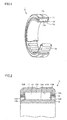
Fig. 1 is a schematic view showing a structure of a radial needle roller bearing. -
Fig. 2 is a schematic cross sectional view showing the structure of the radial needle roller bearing in an enlarged manner. -
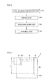
Fig. 3 is a flowchart schematically showing a method for manufacturing the radial needle roller bearing. -
Fig. 4 is a schematic cross sectional view of a heat treatment furnace in a cross section perpendicular to an upper wall and a bottom wall of a reaction chamber. -
Fig. 5 is a schematic cross sectional view of the heat treatment furnace in a cross section perpendicular to the cross section inFig. 4 and perpendicular to the upper wall and the bottom wall of the reaction chamber. -
Fig. 6 is a view showing the influence of flow rates of carbon dioxide gas and hydrogen gas on an undecomposed ammonia fraction. -
Fig. 7 is a view showing the influence of flow rates of carbon dioxide gas and hydrogen gas on an undecomposed ammonia fraction. -
Fig. 8 is a view showing the influence of the flow rates of the carbon dioxide gas and the hydrogen gas on variation in the undecomposed ammonia fraction. - Hereinafter, an embodiment of the present invention will be described with reference to the drawings. In the drawings below, identical or corresponding parts will be designated by the same reference numerals, and the description thereof will not be repeated.
- Referring to
Fig. 1 , a radialneedle roller bearing 1 as a rolling bearing in the present embodiment includes an annularouter race 11, an annularinner race 12 arranged insideouter race 11, and a plurality ofneedle rollers 13 as rolling elements arranged betweenouter race 11 andinner race 12 and held in anannular cage 14. An outerrace rolling surface 11A is formed on an inner peripheral surface ofouter race 11, and an innerrace rolling surface 12A is formed on an outer peripheral surface ofinner race 12.Outer race 11 andinner race 12 are arranged such that innerrace rolling surface 12A and outerrace rolling surface 11A face each other. Further, the plurality ofneedle rollers 13 each have an outerperipheral surface 13A in contact with innerrace rolling surface 12A and outerrace rolling surface 11A, and are arranged bycage 14 at a prescribed pitch in a circumferential direction, to be held on an annular raceway in a rollable manner. With the above structure,outer race 11 andinner race 12 of radialneedle roller bearing 1 are relatively rotatable with respect to each other. - Referring now to
Fig. 2 ,cage 14 as a bearing part holdingneedle roller 13 has an endsurface holding surface 14B facing anend surface 13B ofneedle roller 13. Since endsurface holding surface 14B is subjected to drilling wear byend surface 13B ofneedle roller 13, it is required to have a high wear resistance. Thus,cage 14 in the present embodiment has anitride layer 14A formed by gas nitrocarburizing in a surface layer portion thereof, and thereby endsurface 13B is provided with a high wear resistance.Nitride layer 14A is formed by a gas nitrocarburizing method in one embodiment of the present invention described below. - Referring to
Fig. 3 , in a method for manufacturing radialneedle roller bearing 1 includingcage 14 in the present embodiment, firstly, a steel material preparation step is performed as a step (S10). In this step (S10), for example, a JIS SPCC material as a cold-rolled steel strip or a JIS SPHD material as a hot-rolled soft steel strip is prepared. - Next, a shaping step is performed as a step (S20). In this step (S20), the prepared steel strip is shaped into a desired shape to fabricate a shaped member having the shape of
cage 14. Specifically, processes such as formation of pockets for holding the needle rollers, bending of the steel strip into the shape of the annular cage, and the like are performed. - Next, a nitrocarburizing step is performed as a step (S30). In this step (S30), the shaped member is heated within a heat treatment furnace into which a heat treatment gas is introduced, to form a nitride layer in a surface layer portion of the shaped member. On this occasion, as the heat treatment gas, a heat treatment gas containing ammonia gas, at least one of carbon dioxide gas and hydrogen gas, and nitrogen gas, and having the remainder formed of an impurity is used. It is noted that the nitrogen gas is not essential in the heat treatment gas, and, by omitting the nitrogen gas, a heat treatment gas containing ammonia gas and at least one of carbon dioxide gas and hydrogen gas, and having the remainder formed of an impurity may be used.
- In the gas nitrocarburizing method in the present embodiment, since at least one of carbon dioxide gas and hydrogen gas is added to the heat treatment gas, gas nitrocarburizing processing implementing both cost reduction and reduction of variation in quality can be achieved. As a result,
cage 14 fabricated to havenitride layer 14A formed on the shaped member serves as a cage implementing both reduction of cost for heat treatment and reduction of variation in quality. - Next, an assembly step is performed as a step (S40). In this step (S40),
cage 14 fabricated as described above is combined withouter race 11,inner race 12,needle rollers 13, and the like prepared separately, to assemble radialneedle roller bearing 1. - Preferably, in step (S30), a ratio of a flow rate of the carbon dioxide gas to a total flow rate of the heat treatment gas introduced into the heat treatment furnace is more than or equal to 5% and less than or equal to 20%. Thereby, a speed of a decomposition reaction of ammonia can be sufficiently reduced.
- Preferably, in step (S30), a ratio of a flow rate of the hydrogen gas to the total flow rate of the heat treatment gas introduced into the heat treatment furnace is more than or equal to 10% and less than or equal to 50%. Thereby, the speed of the decomposition reaction of ammonia can be sufficiently reduced.
- Preferably, in step (S30),
nitride layer 14A is formed by heating the shaped member to a temperature range of more than or equal to 550°C and less than or equal to 650°C within the heat treatment furnace. Thereby, high-quality nitride layer 14A can be easily formed. - Preferably, in step (S30), an atmosphere within the heat treatment furnace is obtained at a plurality of positions to control an undecomposed ammonia fraction in the atmosphere. More specifically, the undecomposed ammonia fraction in the atmosphere is preferably controlled such that, for example, a difference between a maximum value and a minimum value of the undecomposed ammonia fraction in the atmosphere obtained at the plurality of positions within the heat treatment furnace is less than or equal to 0.8% by volume. Thereby, variation in the quality of
cages 14 can be reduced more reliably. - On this occasion, the undecomposed ammonia fraction in the atmosphere is preferably adjusted by adjusting a flow rate of the at least one of the carbon dioxide gas and the hydrogen gas in the heat treatment gas. Thereby, the undecomposed ammonia fraction in the atmosphere can be easily adjusted. In particular, by adjusting the flow rate of the at least one of the carbon dioxide gas and the hydrogen gas in the heat treatment gas so as to reduce the difference between the maximum value and the minimum value of the undecomposed ammonia fraction in the atmosphere obtained at the plurality of positions within the heat treatment furnace, variation in the quality of
cages 14 can be easily reduced. - Preferably, in step (S30), the shaped member is heated within the heat treatment furnace with an atmosphere within the heat treatment furnace being stirred by a stirring fan arranged within the heat treatment furnace. Thereby, variation in the quality of
cages 14 can be reduced further easily. - Hereinafter, an example of the present invention will be described. An experiment was conducted to confirm the effect caused by adding at least one of carbon dioxide gas and hydrogen gas to a heat treatment gas in gas nitrocarburizing processing. The procedure of the experiment was as follows.
- In gas nitrocarburizing processing using a heat treatment gas prepared by adding ammonia gas to nitrogen gas as a base gas, at least one of carbon dioxide gas and hydrogen gas was further added to the heat treatment gas to investigate the influence of the addition on an undecomposed ammonia fraction.
-
Figs. 4 and5 show a heat treatment furnace used for the experiment. Referring toFigs. 4 and5 , aheat treatment furnace 5 is a heat treatment furnace capable of holding a workpiece within areaction chamber 51 and performing the gas nitrocarburizing processing on the workpiece.Reaction chamber 51 has a shape with a diameter of 460 mm and a height of 700 mm. A stirringfan 52 is provided on an upper wall ofreaction chamber 51. The experiment was conducted with stirringfan 52 being always operated at a rotation speed of 1600 rpm. Further, as shown inFig. 4 ,reaction chamber 51 is provided with afirst sampling tube 55 and asecond sampling tube 56 extending from the upper wall toward a bottom wall. Further, referring toFig. 5 ,reaction chamber 51 is provided with agas inlet 53 for introducing ammonia gas, nitrogen gas, carbon dioxide gas, and hydrogen gas intoreaction chamber 51, and anexhaust outlet 54 exhausting the gas withinreaction chamber 51 to the outside. In addition, as shown inFig. 4 , anopening 55A offirst sampling tube 55 for obtaining an atmosphere withinreaction chamber 51 is located in a region having a distance L1 from the upper wall of 300 mm. Further, anopening 56A ofsecond sampling tube 56 is located in a region having a distance L2 from the upper wall of 500 mm. Thereby,first sampling tube 55 andsecond sampling tube 56 can obtain the atmosphere withinreaction chamber 51 in an upper region and a lower region, respectively. - Then, a constant amount of ammonia gas was introduced into
reaction chamber 51, and carbon dioxide gas, hydrogen gas, and nitrogen gas were introduced with flow rates thereof being changed so as to obtain a constant total flow rate of the heat treatment gas, to analyze the undecomposed ammonia fraction withinreaction chamber 51 obtained fromfirst sampling tube 55 andsecond sampling tube 56. The temperature of the atmosphere withinreaction chamber 51 was set at two levels, that is, 550°C and 650°C, which are suitable for the gas nitrocarburizing processing. - The undecomposed ammonia fraction was analyzed with a non-dispersive infrared gas analyzer (FA1000 manufactured by Horiba, Ltd.). It is noted that the experiment was conducted with the analyzer and the sampling tubes being kept at more than or equal to 65°C using a band heater and a heat insulating material in order to avoid solid ammonium carbonate from being produced within the analyzer and the sampling tubes and affecting the experiment. Table 1 shows experimental conditions, and Table 2 shows experimental results.
[Table 1] Heating temperature (°C) Total flow rate (L/min) NH3 flow rate (L/min) N2 flow rate (L/min) H2 CO2 flow rate (L/min) flow rate ratio (%) flow rate (L/min) flow rate ratio (%) 1 550 6 3 3 0 0 0 0 2 550 6 3 1.8 1.2 20 0 0 3 550 6 3 2.7 0 0 0.3 5 4 550 6 3 1.5 1.2 20 0.3 5 5 550 6 3 1.8 0 0 1.2 20 6 550 6 3 0.6 1.2 20 1.2 20 7 650 6 3 3 0 0 0 0 8 650 6 3 1.8 1.2 20 0 0 9 650 6 3 2.7 0 0 0.3 5 10 650 6 3 1.5 1.2 20 0.3 5 11 650 6 3 1.8 0 0 1.2 20 12 650 6 3 0.6 1.2 20 1.2 20 [Table 2] Temperature (°C) Undecomposed NH3 fraction (% by volume) Measurement point A (distance from upper wall:300 mm) Measurement point B (distance from upper wall : 500 mm) Average Variation 1 550 30.8 30.8 30.8 0.0 2 550 37.1 37.0 37.1 0.1 3 550 35.3 35.4 35.4 0.1 4 550 39.8 39.8 39.8 0.0 5 550 34.2 34.2 34.2 0.0 6 550 39.4 39.4 39.4 0.0 7 650 6.4 4.9 5.7 1.5 8 650 8.0 7.3 7.7 0.7 9 650 7.4 6.6 7.0 0.8 10 650 8.8 8.3 8.6 0.5 11 650 7.3 7.0 7.2 0.3 12 650 9.2 9.0 9.1 0.2 - Referring to Tables 1 and 2, although the total flow rate of the heat treatment gas and the flow rate of the ammonia gas were identical, undecomposed ammonia fractions at a heating temperature of 650°C are reduced to about one fifth of those at a heating temperature of 550°C. This is considered to be because an increase in temperature causes an increase in a reaction speed of the decomposition reaction represented by formula (1).
- Next, the above experimental results are depicted in graph form to analyze the experimental results.
Figs. 6 and7 are views showing the relation between the flow rate of carbon dioxide and the undecomposed ammonia fraction at heating temperatures of 550°C and 650°C, respectively. InFigs. 6 and7 , a hollow data point indicates a value in a case where the flow rate of the hydrogen gas was 0, and a solid data point indicates a value in a case where the flow rate of the hydrogen gas was 1.2 L/min. Further, inFigs. 6 and7 , the axis of abscissas represents the flow rate of the carbon dioxide gas, and the axis of ordinates represents the undecomposed ammonia fraction. An undecomposed ammonia fraction on the axis of ordinates indicates an average value of analysis values of the atmosphere respectively obtained atfirst sampling tube 55 andsecond sampling tube 56. - Referring to
Figs. 6 and7 , in the case where the flow rate of the hydrogen gas is 1.2 L/min, the value of the undecomposed ammonia fraction is clearly increased when compared with that in the case where the flow rate of the hydrogen gas is 0. This is considered to indicate that the speed of the decomposition reaction of the ammonia gas was reduced by adding the hydrogen gas to the heat treatment gas, and more undecomposed ammonia remained withinreaction chamber 51. Based on this, it is considered that the hydrogen gas serves as a negative catalyst which slows down the speed of the decomposition reaction of the ammonia gas in the heat treatment gas for the gas nitrocarburizing processing, and the amount of usage of the ammonia gas can be reduced by adding the hydrogen gas. - Further, referring to
Figs. 6 and7 , the undecomposed ammonia fraction increases as the flow rate of the carbon dioxide gas increases. Based on this, it is considered that the carbon dioxide gas also serves as a negative catalyst which slows down the speed of the decomposition reaction of the ammonia gas in the heat treatment gas for the gas nitrocarburizing processing, and the amount of usage of the ammonia gas can be reduced by adding the carbon dioxide gas. More specifically, referring to Tables 1 and 2, the undecomposed ammonia fractions underconditions conditions 1 and 7 in which the hydrogen gas and the carbon dioxide gas were not added. Based on the above results, it has been confirmed that, by adding the carbon dioxide gas and the hydrogen gas to the heat treatment gas in the gas nitrocarburizing processing, the amount of usage of expensive ammonia gas can be considerably reduced, and reduction of cost for heat treatment can be achieved. - Next, the influence of adding the carbon dioxide gas and the hydrogen gas on variation in the undecomposed ammonia fraction within the heat treatment furnace will be discussed with reference to
Fig. 8 . InFig. 8 , the axis of abscissas represents the flow rate of carbon dioxide, and the axis of ordinates represents variation in the undecomposed ammonia fraction. A variation in the undecomposed ammonia fraction on the axis of ordinates indicates a difference between an undecomposed ammonia fraction in the atmosphere obtained atfirst sampling tube 55 and an undecomposed ammonia fraction in the atmosphere obtained atsecond sampling tube 56. Further, inFig. 8 , a circular data point indicates a value at a heating temperature of 550°C, and a square data point indicates a value at a heating temperature of 650°C. Furthermore, inFig. 8 , a hollow data point indicates a value in the case where the flow rate of the hydrogen gas was 0, and a solid data point indicates a value in the case where the flow rate of the hydrogen gas was 1.2 L/min. - Referring to
Fig. 8 , at a heating temperature of 550°C, variation in the undecomposed ammonia fraction withinreaction chamber 51 is small regardless of whether the carbon dioxide gas and the hydrogen gas were added. On the other hand, at a heating temperature of 650°C, under a condition in which carbon dioxide and hydrogen were not added, the undecomposed ammonia fraction varies significantly within the furnace. This is considered to be because, at a heating temperature of 650°C, the speed of the decomposition reaction of the ammonia gas was increased, and the undecomposed ammonia fraction was relatively increased in the upper region close togas inlet 53 for introducing the ammonia gas. In contrast, at a heating temperature of 650°C, the variation is reduced when any of the flow rates of the carbon dioxide gas and the hydrogen gas is increased. In addition, it has been found that, undercondition 12 in which the flow rates of the carbon dioxide gas and the hydrogen gas were both set to 1.2 L/min, the variation is reduced to 0.2% by volume. Based on this, it has been confirmed that, by adding at least one of the carbon dioxide gas and the hydrogen gas to the heat treatment gas, variation in the undecomposed ammonia fraction within the heat treatment furnace can be reduced, and variation in quality can be suppressed. - It is noted that there are many substances serving as a negative catalyst which slows down the speed of the decomposition reaction of the ammonia gas. However, considering that reduction of environmental load and suppression of manufacturing cost are preferable, it is desirable that a negative catalyst to be adopted does not contain chlorine and the like which do not exist much in the air, and is inexpensive. From such a viewpoint, it can be said that the gas nitrocarburizing method in accordance with the present invention adopting at least one of carbon dioxide and hydrogen as a negative catalyst is an effective gas nitrocarburizing method.
- It should be understood that the embodiment and the example disclosed herein are illustrative and non-restrictive in every respect. The scope of the present invention is defined by the scope of the claims, rather than the description above, and is intended to include any modifications within the scope and meaning equivalent to the scope of the claims.
- The gas nitrocarburizing method and the method for manufacturing a bearing part in accordance with the present invention are particularly advantageously applicable to a gas nitrocarburizing method and a method for manufacturing a bearing part which are required to implement both cost reduction and reduction of variation in quality.
- 1: radial needle roller bearing; 5: heat treatment furnace; 11: outer race; 11A: outer race rolling surface; 12: inner race; 12A: inner race rolling surface; 13: needle roller; 13A: outer peripheral surface; 13B: end surface; 14: cage; 14A: nitride layer; 14B: end surface holding surface; 51: reaction chamber; 52: stirring fan; 53: gas inlet; 54: exhaust outlet; 55: first sampling tube; 55A, 56A: opening; 56: second sampling tube.
Claims (18)
- A gas nitrocarburizing method forming a nitride layer (14A) in a surface layer portion of a workpiece (14) made of steel by heating said workpiece (14) within a heat treatment furnace (5) into which a heat treatment gas is introduced,
said heat treatment gas containing ammonia gas and at least one of carbon dioxide gas and hydrogen gas, and having a remainder formed of an impurity. - The gas nitrocarburizing method according to claim 1, wherein a ratio of a flow rate of said carbon dioxide gas to a total flow rate of said heat treatment gas introduced into said heat treatment furnace (5) is more than or equal to 5% and less than or equal to 20%.
- The gas nitrocarburizing method according to claim 1, wherein a ratio of a flow rate of said hydrogen gas to a total flow rate of said heat treatment gas introduced into said heat treatment furnace (5) is more than or equal to 10% and less than or equal to 50%.
- The gas nitrocarburizing method according to claim 1, wherein said nitride layer (14A) is formed by heating said workpiece (14) to a temperature range of more than or equal to 550°C and less than or equal to 650°C within said heat treatment furnace (5).
- The gas nitrocarburizing method according to claim 1, wherein an atmosphere within said heat treatment furnace (5) is obtained at a plurality of positions to control an undecomposed ammonia fraction in said atmosphere.
- The gas nitrocarburizing method according to claim 5, wherein the undecomposed ammonia fraction in said atmosphere is controlled such that a difference between a maximum value and a minimum value of the undecomposed ammonia fraction in said atmosphere obtained at the plurality of positions within said heat treatment furnace (5) is less than or equal to 0.8% by volume.
- The gas nitrocarburizing method according to claim 5, wherein the undecomposed ammonia fraction in said atmosphere is adjusted by adjusting a flow rate of the at least one of the carbon dioxide gas and the hydrogen gas in said heat treatment gas.
- The gas nitrocarburizing method according to claim 1, wherein said workpiece (14) is heated within said heat treatment furnace (5) with an atmosphere within said heat treatment furnace (5) being stirred by a stirring fan (52) arranged within said heat treatment furnace (5).
- A method for manufacturing a bearing part (14), comprising the steps of:preparing a steel material;fabricating a shaped member (14) by shaping said steel material; andforming a nitride layer (14A) in a surface layer portion of said shaped member (14),in the step of forming said nitride layer (14A), said nitride layer (14A) being formed by a gas nitrocarburizing method as recited in claim 1.
- A gas nitrocarburizing method forming a nitride layer (14A) in a surface layer portion of a workpiece (14) made of steel by heating said workpiece (14) within a heat treatment furnace (5) into which a heat treatment gas is introduced,
said heat treatment gas containing ammonia gas, at least one of carbon dioxide gas and hydrogen gas, and nitrogen gas, and having a remainder formed of an impurity. - The gas nitrocarburizing method according to claim 10, wherein a ratio of a flow rate of said carbon dioxide gas to a total flow rate of said heat treatment gas introduced into said heat treatment furnace (5) is more than or equal to 5% and less than or equal to 20%.
- The gas nitrocarburizing method according to claim 10, wherein a ratio of a flow rate of said hydrogen gas to a total flow rate of said heat treatment gas introduced into said heat treatment furnace (5) is more than or equal to 10% and less than or equal to 50%.
- The gas nitrocarburizing method according to claim 10, wherein said nitride layer (14A) is formed by heating said workpiece (14) to a temperature range of more than or equal to 550°C and less than or equal to 650°C within said heat treatment furnace (5).
- The gas nitrocarburizing method according to claim 10, wherein an atmosphere within said heat treatment furnace (5) is obtained at a plurality of positions to control an undecomposed ammonia fraction in said atmosphere.
- The gas nitrocarburizing method according to claim 14, wherein the undecomposed ammonia fraction in said atmosphere is controlled such that a difference between a maximum value and a minimum value of the undecomposed ammonia fraction in said atmosphere obtained at the plurality of positions within said heat treatment furnace (5) is less than or equal to 0.8% by volume.
- The gas nitrocarburizing method according to claim 14, wherein the undecomposed ammonia fraction in said atmosphere is adjusted by adjusting a flow rate of the at least one of the carbon dioxide gas and the hydrogen gas in said heat treatment gas.
- The gas nitrocarburizing method according to claim 10, wherein said workpiece (14) is heated within said heat treatment furnace (5) with an atmosphere within said heat treatment furnace (5) being stirred by a stirring fan (52) arranged within said heat treatment furnace (5).
- A method for manufacturing a bearing part (14), comprising the steps of:preparing a steel material;fabricating a shaped member (14) by shaping said steel material; andforming a nitride layer (14A) in a surface layer portion of said shaped member (14),in the step of forming said nitride layer (14A), said nitride layer (14A) being formed by a gas nitrocarburizing method as recited in claim 10.
Applications Claiming Priority (2)
| Application Number | Priority Date | Filing Date | Title |
|---|---|---|---|
| JP2011093127A JP5744610B2 (en) | 2011-04-19 | 2011-04-19 | Gas soft nitriding method |
| PCT/JP2012/059671 WO2012144365A1 (en) | 2011-04-19 | 2012-04-09 | Gas soft nitriding method and method for manufacturing bearing component |
Publications (2)
| Publication Number | Publication Date |
|---|---|
| EP2700732A1 true EP2700732A1 (en) | 2014-02-26 |
| EP2700732A4 EP2700732A4 (en) | 2014-10-22 |
Family
ID=47041477
Family Applications (1)
| Application Number | Title | Priority Date | Filing Date |
|---|---|---|---|
| EP12774037.1A Ceased EP2700732A4 (en) | 2011-04-19 | 2012-04-09 | GAS PHASE SOFT NITRURATION METHOD AND METHOD FOR MANUFACTURING SUPPORT ELEMENT |
Country Status (5)
| Country | Link |
|---|---|
| US (1) | US10047429B2 (en) |
| EP (1) | EP2700732A4 (en) |
| JP (1) | JP5744610B2 (en) |
| CN (1) | CN103502500B (en) |
| WO (1) | WO2012144365A1 (en) |
Families Citing this family (2)
| Publication number | Priority date | Publication date | Assignee | Title |
|---|---|---|---|---|
| JP6576209B2 (en) * | 2015-10-27 | 2019-09-18 | 光洋サーモシステム株式会社 | Nitriding processing apparatus and nitriding processing method |
| CN110029304A (en) * | 2019-03-12 | 2019-07-19 | 常州铂林热处理有限公司 | A kind of atmosphere nitridation of steel alloy, oxidation processing technique |
Family Cites Families (14)
| Publication number | Priority date | Publication date | Assignee | Title |
|---|---|---|---|---|
| US4496401A (en) * | 1981-10-15 | 1985-01-29 | Lucas Industries | Corrosion resistant steel components and method of manufacture thereof |
| JPS58174572A (en) | 1982-04-02 | 1983-10-13 | Oriental Eng Kk | Gas soft nitriding method |
| DD222416A1 (en) | 1983-07-07 | 1985-05-15 | Adw Ddr | DEVICE FOR CONTROLLING AMMONIA-CONTAINING GASES |
| DE3937699A1 (en) * | 1989-11-13 | 1991-05-16 | Thaelmann Schwermaschbau Veb | Producing epsilon carbonitride coatings on ferrous components - by controlling gas mixt. compsn. with respect to nitriding and carburising indices required to produce predetermined coating compsn. |
| JPH09279296A (en) * | 1996-04-16 | 1997-10-28 | Nippon Steel Corp | Steel for soft nitriding with excellent cold forgeability |
| DE19652125C1 (en) | 1996-12-14 | 1998-04-30 | Volker Dipl Ing Leverkus | Nitriding or carbonitriding atmosphere regulation |
| JP3976221B2 (en) | 2000-08-28 | 2007-09-12 | Dowaホールディングス株式会社 | Gas soft nitriding method |
| JP2003119548A (en) * | 2001-10-15 | 2003-04-23 | Nippon Steel Corp | Steel sheet for nitrocarburizing treatment excellent in press formability and method for producing the same |
| JP4284405B2 (en) | 2002-10-17 | 2009-06-24 | 独立行政法人物質・材料研究機構 | Tapping screw and its manufacturing method |
| JP4885606B2 (en) | 2006-04-28 | 2012-02-29 | Ntn株式会社 | Carbonitriding method and machine part manufacturing method |
| JP2009041063A (en) * | 2007-08-08 | 2009-02-26 | Air Water Inc | Method for gas nitriding treatment of hot-molding mold and hot-molding mold obtained thereby |
| JP2010058164A (en) * | 2008-09-05 | 2010-03-18 | Daido Steel Co Ltd | Method of manufacturing die-cast mold |
| WO2010147224A1 (en) * | 2009-06-17 | 2010-12-23 | 新日本製鐵株式会社 | Steel for nitriding and nitrided steel components |
| JP5629436B2 (en) * | 2009-07-21 | 2014-11-19 | オリエンタルエンヂニアリング株式会社 | Surface hardening processing apparatus and surface hardening processing method |
-
2011
- 2011-04-19 JP JP2011093127A patent/JP5744610B2/en active Active
-
2012
- 2012-04-09 CN CN201280018454.0A patent/CN103502500B/en active Active
- 2012-04-09 WO PCT/JP2012/059671 patent/WO2012144365A1/en not_active Ceased
- 2012-04-09 EP EP12774037.1A patent/EP2700732A4/en not_active Ceased
- 2012-04-09 US US14/112,871 patent/US10047429B2/en active Active
Also Published As
| Publication number | Publication date |
|---|---|
| EP2700732A4 (en) | 2014-10-22 |
| JP5744610B2 (en) | 2015-07-08 |
| CN103502500A (en) | 2014-01-08 |
| JP2012224913A (en) | 2012-11-15 |
| US20140041763A1 (en) | 2014-02-13 |
| WO2012144365A1 (en) | 2012-10-26 |
| US10047429B2 (en) | 2018-08-14 |
| CN103502500B (en) | 2016-08-10 |
Similar Documents
| Publication | Publication Date | Title |
|---|---|---|
| CN102362000B (en) | High-strength and high-ductility steel for spring, method for producing same, and spring | |
| US9062355B2 (en) | Carbonitriding method, machinery component fabrication method, and machinery component | |
| EP2405028A2 (en) | Method of heat treatment for steel, method of producing mechanical component, and mechanical component | |
| US9611533B2 (en) | Manufacturing method of machine component | |
| US10047429B2 (en) | Gas nitrocarburizing method and method for manufacturing bearing part | |
| US8128761B2 (en) | Carbonitriding method, machinery component fabrication method, and machinery component | |
| WO2011115255A1 (en) | Spring steel and surface treatment method for steel material | |
| JP2010285642A (en) | Heat-treatment method of steel, manufacturing method of machine part and machine part | |
| JP2007100126A (en) | Rolling member and ball bearing | |
| KR101531347B1 (en) | Method for manufacturing iron-based diffusion bonding powders | |
| JP2010024492A (en) | Heat-treatment method for steel, method for manufacturing machine component, and machine component | |
| JP2004217958A (en) | Method of nitriding metal materials | |
| JP2011074420A (en) | Heat-treatment method for steel, method for manufacturing machine component, and machine component | |
| JP6071365B2 (en) | Manufacturing method of machine parts | |
| JP5429730B2 (en) | Manufacturing method of machine parts and machine parts | |
| JP5429729B2 (en) | Manufacturing method of machine parts and machine parts | |
| JP2009057606A (en) | Carbonitriding method, machine part manufacturing method, machine part and heat treatment furnace | |
| JP2009299163A (en) | Heat-treatment method for steel, method for manufacturing machine parts, and machine parts | |
| US20090165896A1 (en) | Carbonitriding Method, Machinery Component Fabrication Method, and Machinery Component | |
| KR20180022995A (en) | Production method for alloy steel powder for powder metallurgy | |
| KR20180043821A (en) | METHOD FOR MANUFACTURING ALLOY POWDER FOR POWDER METAL | |
| KR20180033567A (en) | Production method for alloy steel powder for powder metallurgy | |
| JP2011074412A (en) | Heat-treatment method for steel, method for manufacturing machine component, and machine component | |
| JP2007100125A (en) | ROLLING MEMBER MANUFACTURING METHOD, ROLLING MEMBER AND ROLLING BEARING | |
| WO2017043095A1 (en) | Production method for alloy steel powder for powder metallurgy |
Legal Events
| Date | Code | Title | Description |
|---|---|---|---|
| PUAI | Public reference made under article 153(3) epc to a published international application that has entered the european phase |
Free format text: ORIGINAL CODE: 0009012 |
|
| 17P | Request for examination filed |
Effective date: 20131016 |
|
| AK | Designated contracting states |
Kind code of ref document: A1 Designated state(s): AL AT BE BG CH CY CZ DE DK EE ES FI FR GB GR HR HU IE IS IT LI LT LU LV MC MK MT NL NO PL PT RO RS SE SI SK SM TR |
|
| DAX | Request for extension of the european patent (deleted) | ||
| A4 | Supplementary search report drawn up and despatched |
Effective date: 20140923 |
|
| RIC1 | Information provided on ipc code assigned before grant |
Ipc: C21D 9/40 20060101ALI20140917BHEP Ipc: C21D 1/76 20060101ALI20140917BHEP Ipc: C21D 9/38 20060101ALI20140917BHEP Ipc: C23C 8/26 20060101ALI20140917BHEP Ipc: C21D 1/74 20060101ALI20140917BHEP Ipc: C21D 9/36 20060101ALI20140917BHEP Ipc: C23C 8/32 20060101AFI20140917BHEP Ipc: C21D 1/06 20060101ALI20140917BHEP |
|
| STAA | Information on the status of an ep patent application or granted ep patent |
Free format text: STATUS: EXAMINATION IS IN PROGRESS |
|
| 17Q | First examination report despatched |
Effective date: 20170609 |
|
| REG | Reference to a national code |
Ref country code: DE Ref legal event code: R003 |
|
| STAA | Information on the status of an ep patent application or granted ep patent |
Free format text: STATUS: THE APPLICATION HAS BEEN REFUSED |
|
| 18R | Application refused |
Effective date: 20180703 |