EP2700490A1 - Method and device for applying protective sheeting of polymer material to a pipeline - Google Patents
Method and device for applying protective sheeting of polymer material to a pipeline Download PDFInfo
- Publication number
- EP2700490A1 EP2700490A1 EP13193390.5A EP13193390A EP2700490A1 EP 2700490 A1 EP2700490 A1 EP 2700490A1 EP 13193390 A EP13193390 A EP 13193390A EP 2700490 A1 EP2700490 A1 EP 2700490A1
- Authority
- EP
- European Patent Office
- Prior art keywords
- pipeline
- carriage
- protective sheeting
- sector
- longitudinal axis
- Prior art date
- Legal status (The legal status is an assumption and is not a legal conclusion. Google has not performed a legal analysis and makes no representation as to the accuracy of the status listed.)
- Withdrawn
Links
- 230000001681 protective effect Effects 0.000 title claims abstract description 66
- 239000002861 polymer material Substances 0.000 title claims abstract description 29
- 238000000034 method Methods 0.000 title claims abstract description 22
- 238000004804 winding Methods 0.000 claims abstract description 7
- 238000001125 extrusion Methods 0.000 claims description 38
- 230000000295 complement effect Effects 0.000 claims description 4
- 230000005484 gravity Effects 0.000 claims description 4
- 125000006850 spacer group Chemical group 0.000 claims description 3
- 238000005520 cutting process Methods 0.000 claims description 2
- 238000000576 coating method Methods 0.000 description 28
- 239000011248 coating agent Substances 0.000 description 27
- 239000002184 metal Substances 0.000 description 10
- 238000005096 rolling process Methods 0.000 description 6
- 238000003860 storage Methods 0.000 description 6
- 239000011324 bead Substances 0.000 description 5
- 238000005304 joining Methods 0.000 description 4
- 238000010438 heat treatment Methods 0.000 description 3
- -1 polyethylene Polymers 0.000 description 3
- 239000007787 solid Substances 0.000 description 3
- 238000003466 welding Methods 0.000 description 3
- WNTGYJSOUMFZEP-UHFFFAOYSA-N 2-(4-chloro-2-methylphenoxy)propanoic acid Chemical compound OC(=O)C(C)OC1=CC=C(Cl)C=C1C WNTGYJSOUMFZEP-UHFFFAOYSA-N 0.000 description 2
- 239000004593 Epoxy Substances 0.000 description 2
- 239000004567 concrete Substances 0.000 description 2
- 238000001816 cooling Methods 0.000 description 2
- 229920001577 copolymer Polymers 0.000 description 2
- 239000003822 epoxy resin Substances 0.000 description 2
- 230000004927 fusion Effects 0.000 description 2
- 230000006698 induction Effects 0.000 description 2
- 229920000647 polyepoxide Polymers 0.000 description 2
- 239000011378 shotcrete Substances 0.000 description 2
- 239000007921 spray Substances 0.000 description 2
- 238000005507 spraying Methods 0.000 description 2
- XLYOFNOQVPJJNP-UHFFFAOYSA-N water Substances O XLYOFNOQVPJJNP-UHFFFAOYSA-N 0.000 description 2
- 239000004698 Polyethylene Substances 0.000 description 1
- 239000004743 Polypropylene Substances 0.000 description 1
- 241000836710 Trichaptum sector Species 0.000 description 1
- 239000000853 adhesive Substances 0.000 description 1
- 230000001070 adhesive effect Effects 0.000 description 1
- 230000005540 biological transmission Effects 0.000 description 1
- 238000005422 blasting Methods 0.000 description 1
- 239000004568 cement Substances 0.000 description 1
- 239000003638 chemical reducing agent Substances 0.000 description 1
- 238000010276 construction Methods 0.000 description 1
- 230000007797 corrosion Effects 0.000 description 1
- 238000005260 corrosion Methods 0.000 description 1
- 230000001066 destructive effect Effects 0.000 description 1
- 238000009434 installation Methods 0.000 description 1
- 238000004519 manufacturing process Methods 0.000 description 1
- 239000000463 material Substances 0.000 description 1
- 229920000573 polyethylene Polymers 0.000 description 1
- 229920000642 polymer Polymers 0.000 description 1
- 229920000098 polyolefin Polymers 0.000 description 1
- 229920001155 polypropylene Polymers 0.000 description 1
- 230000001360 synchronised effect Effects 0.000 description 1
Images



Classifications
-
- B—PERFORMING OPERATIONS; TRANSPORTING
- B05—SPRAYING OR ATOMISING IN GENERAL; APPLYING FLUENT MATERIALS TO SURFACES, IN GENERAL
- B05D—PROCESSES FOR APPLYING FLUENT MATERIALS TO SURFACES, IN GENERAL
- B05D1/00—Processes for applying liquids or other fluent materials
- B05D1/26—Processes for applying liquids or other fluent materials performed by applying the liquid or other fluent material from an outlet device in contact with, or almost in contact with, the surface
- B05D1/265—Extrusion coatings
-
- B—PERFORMING OPERATIONS; TRANSPORTING
- B29—WORKING OF PLASTICS; WORKING OF SUBSTANCES IN A PLASTIC STATE IN GENERAL
- B29C—SHAPING OR JOINING OF PLASTICS; SHAPING OF MATERIAL IN A PLASTIC STATE, NOT OTHERWISE PROVIDED FOR; AFTER-TREATMENT OF THE SHAPED PRODUCTS, e.g. REPAIRING
- B29C63/00—Lining or sheathing, i.e. applying preformed layers or sheathings of plastics; Apparatus therefor
- B29C63/02—Lining or sheathing, i.e. applying preformed layers or sheathings of plastics; Apparatus therefor using sheet or web-like material
- B29C63/04—Lining or sheathing, i.e. applying preformed layers or sheathings of plastics; Apparatus therefor using sheet or web-like material by folding, winding, bending or the like
- B29C63/06—Lining or sheathing, i.e. applying preformed layers or sheathings of plastics; Apparatus therefor using sheet or web-like material by folding, winding, bending or the like around tubular articles
-
- B—PERFORMING OPERATIONS; TRANSPORTING
- B05—SPRAYING OR ATOMISING IN GENERAL; APPLYING FLUENT MATERIALS TO SURFACES, IN GENERAL
- B05C—APPARATUS FOR APPLYING FLUENT MATERIALS TO SURFACES, IN GENERAL
- B05C5/00—Apparatus in which liquid or other fluent material is projected, poured or allowed to flow on to the surface of the work
- B05C5/02—Apparatus in which liquid or other fluent material is projected, poured or allowed to flow on to the surface of the work the liquid or other fluent material being discharged through an outlet orifice by pressure, e.g. from an outlet device in contact or almost in contact, with the work
-
- B—PERFORMING OPERATIONS; TRANSPORTING
- B05—SPRAYING OR ATOMISING IN GENERAL; APPLYING FLUENT MATERIALS TO SURFACES, IN GENERAL
- B05C—APPARATUS FOR APPLYING FLUENT MATERIALS TO SURFACES, IN GENERAL
- B05C9/00—Apparatus or plant for applying liquid or other fluent material to surfaces by means not covered by any preceding group, or in which the means of applying the liquid or other fluent material is not important
- B05C9/08—Apparatus or plant for applying liquid or other fluent material to surfaces by means not covered by any preceding group, or in which the means of applying the liquid or other fluent material is not important for applying liquid or other fluent material and performing an auxiliary operation
- B05C9/12—Apparatus or plant for applying liquid or other fluent material to surfaces by means not covered by any preceding group, or in which the means of applying the liquid or other fluent material is not important for applying liquid or other fluent material and performing an auxiliary operation the auxiliary operation being performed after the application
-
- B—PERFORMING OPERATIONS; TRANSPORTING
- B29—WORKING OF PLASTICS; WORKING OF SUBSTANCES IN A PLASTIC STATE IN GENERAL
- B29C—SHAPING OR JOINING OF PLASTICS; SHAPING OF MATERIAL IN A PLASTIC STATE, NOT OTHERWISE PROVIDED FOR; AFTER-TREATMENT OF THE SHAPED PRODUCTS, e.g. REPAIRING
- B29C65/00—Joining or sealing of preformed parts, e.g. welding of plastics materials; Apparatus therefor
- B29C65/02—Joining or sealing of preformed parts, e.g. welding of plastics materials; Apparatus therefor by heating, with or without pressure
- B29C65/022—Particular heating or welding methods not otherwise provided for
- B29C65/028—Particular heating or welding methods not otherwise provided for making use of inherent heat, i.e. the heat for the joining comes from the moulding process of one of the parts to be joined
-
- B—PERFORMING OPERATIONS; TRANSPORTING
- B29—WORKING OF PLASTICS; WORKING OF SUBSTANCES IN A PLASTIC STATE IN GENERAL
- B29C—SHAPING OR JOINING OF PLASTICS; SHAPING OF MATERIAL IN A PLASTIC STATE, NOT OTHERWISE PROVIDED FOR; AFTER-TREATMENT OF THE SHAPED PRODUCTS, e.g. REPAIRING
- B29C66/00—General aspects of processes or apparatus for joining preformed parts
- B29C66/01—General aspects dealing with the joint area or with the area to be joined
- B29C66/05—Particular design of joint configurations
- B29C66/10—Particular design of joint configurations particular design of the joint cross-sections
- B29C66/11—Joint cross-sections comprising a single joint-segment, i.e. one of the parts to be joined comprising a single joint-segment in the joint cross-section
- B29C66/112—Single lapped joints
-
- B—PERFORMING OPERATIONS; TRANSPORTING
- B29—WORKING OF PLASTICS; WORKING OF SUBSTANCES IN A PLASTIC STATE IN GENERAL
- B29C—SHAPING OR JOINING OF PLASTICS; SHAPING OF MATERIAL IN A PLASTIC STATE, NOT OTHERWISE PROVIDED FOR; AFTER-TREATMENT OF THE SHAPED PRODUCTS, e.g. REPAIRING
- B29C66/00—General aspects of processes or apparatus for joining preformed parts
- B29C66/01—General aspects dealing with the joint area or with the area to be joined
- B29C66/05—Particular design of joint configurations
- B29C66/10—Particular design of joint configurations particular design of the joint cross-sections
- B29C66/11—Joint cross-sections comprising a single joint-segment, i.e. one of the parts to be joined comprising a single joint-segment in the joint cross-section
- B29C66/112—Single lapped joints
- B29C66/1122—Single lap to lap joints, i.e. overlap joints
-
- B—PERFORMING OPERATIONS; TRANSPORTING
- B29—WORKING OF PLASTICS; WORKING OF SUBSTANCES IN A PLASTIC STATE IN GENERAL
- B29C—SHAPING OR JOINING OF PLASTICS; SHAPING OF MATERIAL IN A PLASTIC STATE, NOT OTHERWISE PROVIDED FOR; AFTER-TREATMENT OF THE SHAPED PRODUCTS, e.g. REPAIRING
- B29C66/00—General aspects of processes or apparatus for joining preformed parts
- B29C66/01—General aspects dealing with the joint area or with the area to be joined
- B29C66/05—Particular design of joint configurations
- B29C66/10—Particular design of joint configurations particular design of the joint cross-sections
- B29C66/12—Joint cross-sections combining only two joint-segments; Tongue and groove joints; Tenon and mortise joints; Stepped joint cross-sections
- B29C66/128—Stepped joint cross-sections
- B29C66/1282—Stepped joint cross-sections comprising at least one overlap joint-segment
- B29C66/12821—Stepped joint cross-sections comprising at least one overlap joint-segment comprising at least two overlap joint-segments
-
- B—PERFORMING OPERATIONS; TRANSPORTING
- B29—WORKING OF PLASTICS; WORKING OF SUBSTANCES IN A PLASTIC STATE IN GENERAL
- B29C—SHAPING OR JOINING OF PLASTICS; SHAPING OF MATERIAL IN A PLASTIC STATE, NOT OTHERWISE PROVIDED FOR; AFTER-TREATMENT OF THE SHAPED PRODUCTS, e.g. REPAIRING
- B29C66/00—General aspects of processes or apparatus for joining preformed parts
- B29C66/01—General aspects dealing with the joint area or with the area to be joined
- B29C66/05—Particular design of joint configurations
- B29C66/10—Particular design of joint configurations particular design of the joint cross-sections
- B29C66/12—Joint cross-sections combining only two joint-segments; Tongue and groove joints; Tenon and mortise joints; Stepped joint cross-sections
- B29C66/128—Stepped joint cross-sections
- B29C66/1286—Stepped joint cross-sections comprising at least one bevelled joint-segment
-
- B—PERFORMING OPERATIONS; TRANSPORTING
- B29—WORKING OF PLASTICS; WORKING OF SUBSTANCES IN A PLASTIC STATE IN GENERAL
- B29C—SHAPING OR JOINING OF PLASTICS; SHAPING OF MATERIAL IN A PLASTIC STATE, NOT OTHERWISE PROVIDED FOR; AFTER-TREATMENT OF THE SHAPED PRODUCTS, e.g. REPAIRING
- B29C66/00—General aspects of processes or apparatus for joining preformed parts
- B29C66/50—General aspects of joining tubular articles; General aspects of joining long products, i.e. bars or profiled elements; General aspects of joining single elements to tubular articles, hollow articles or bars; General aspects of joining several hollow-preforms to form hollow or tubular articles
- B29C66/51—Joining tubular articles, profiled elements or bars; Joining single elements to tubular articles, hollow articles or bars; Joining several hollow-preforms to form hollow or tubular articles
- B29C66/53—Joining single elements to tubular articles, hollow articles or bars
- B29C66/532—Joining single elements to the wall of tubular articles, hollow articles or bars
- B29C66/5326—Joining single elements to the wall of tubular articles, hollow articles or bars said single elements being substantially flat
-
- B—PERFORMING OPERATIONS; TRANSPORTING
- B29—WORKING OF PLASTICS; WORKING OF SUBSTANCES IN A PLASTIC STATE IN GENERAL
- B29C—SHAPING OR JOINING OF PLASTICS; SHAPING OF MATERIAL IN A PLASTIC STATE, NOT OTHERWISE PROVIDED FOR; AFTER-TREATMENT OF THE SHAPED PRODUCTS, e.g. REPAIRING
- B29C66/00—General aspects of processes or apparatus for joining preformed parts
- B29C66/50—General aspects of joining tubular articles; General aspects of joining long products, i.e. bars or profiled elements; General aspects of joining single elements to tubular articles, hollow articles or bars; General aspects of joining several hollow-preforms to form hollow or tubular articles
- B29C66/65—General aspects of joining tubular articles; General aspects of joining long products, i.e. bars or profiled elements; General aspects of joining single elements to tubular articles, hollow articles or bars; General aspects of joining several hollow-preforms to form hollow or tubular articles with a relative motion between the article and the welding tool
- B29C66/652—General aspects of joining tubular articles; General aspects of joining long products, i.e. bars or profiled elements; General aspects of joining single elements to tubular articles, hollow articles or bars; General aspects of joining several hollow-preforms to form hollow or tubular articles with a relative motion between the article and the welding tool moving the welding tool around the fixed article
-
- B—PERFORMING OPERATIONS; TRANSPORTING
- B29—WORKING OF PLASTICS; WORKING OF SUBSTANCES IN A PLASTIC STATE IN GENERAL
- B29C—SHAPING OR JOINING OF PLASTICS; SHAPING OF MATERIAL IN A PLASTIC STATE, NOT OTHERWISE PROVIDED FOR; AFTER-TREATMENT OF THE SHAPED PRODUCTS, e.g. REPAIRING
- B29C66/00—General aspects of processes or apparatus for joining preformed parts
- B29C66/70—General aspects of processes or apparatus for joining preformed parts characterised by the composition, physical properties or the structure of the material of the parts to be joined; Joining with non-plastics material
- B29C66/72—General aspects of processes or apparatus for joining preformed parts characterised by the composition, physical properties or the structure of the material of the parts to be joined; Joining with non-plastics material characterised by the structure of the material of the parts to be joined
- B29C66/723—General aspects of processes or apparatus for joining preformed parts characterised by the composition, physical properties or the structure of the material of the parts to be joined; Joining with non-plastics material characterised by the structure of the material of the parts to be joined being multi-layered
- B29C66/7232—General aspects of processes or apparatus for joining preformed parts characterised by the composition, physical properties or the structure of the material of the parts to be joined; Joining with non-plastics material characterised by the structure of the material of the parts to be joined being multi-layered comprising a non-plastics layer
- B29C66/72321—General aspects of processes or apparatus for joining preformed parts characterised by the composition, physical properties or the structure of the material of the parts to be joined; Joining with non-plastics material characterised by the structure of the material of the parts to be joined being multi-layered comprising a non-plastics layer consisting of metals or their alloys
-
- B—PERFORMING OPERATIONS; TRANSPORTING
- B29—WORKING OF PLASTICS; WORKING OF SUBSTANCES IN A PLASTIC STATE IN GENERAL
- B29C—SHAPING OR JOINING OF PLASTICS; SHAPING OF MATERIAL IN A PLASTIC STATE, NOT OTHERWISE PROVIDED FOR; AFTER-TREATMENT OF THE SHAPED PRODUCTS, e.g. REPAIRING
- B29C66/00—General aspects of processes or apparatus for joining preformed parts
- B29C66/70—General aspects of processes or apparatus for joining preformed parts characterised by the composition, physical properties or the structure of the material of the parts to be joined; Joining with non-plastics material
- B29C66/74—Joining plastics material to non-plastics material
- B29C66/742—Joining plastics material to non-plastics material to metals or their alloys
-
- B—PERFORMING OPERATIONS; TRANSPORTING
- B29—WORKING OF PLASTICS; WORKING OF SUBSTANCES IN A PLASTIC STATE IN GENERAL
- B29C—SHAPING OR JOINING OF PLASTICS; SHAPING OF MATERIAL IN A PLASTIC STATE, NOT OTHERWISE PROVIDED FOR; AFTER-TREATMENT OF THE SHAPED PRODUCTS, e.g. REPAIRING
- B29C66/00—General aspects of processes or apparatus for joining preformed parts
- B29C66/80—General aspects of machine operations or constructions and parts thereof
- B29C66/81—General aspects of the pressing elements, i.e. the elements applying pressure on the parts to be joined in the area to be joined, e.g. the welding jaws or clamps
- B29C66/814—General aspects of the pressing elements, i.e. the elements applying pressure on the parts to be joined in the area to be joined, e.g. the welding jaws or clamps characterised by the design of the pressing elements, e.g. of the welding jaws or clamps
- B29C66/8141—General aspects of the pressing elements, i.e. the elements applying pressure on the parts to be joined in the area to be joined, e.g. the welding jaws or clamps characterised by the design of the pressing elements, e.g. of the welding jaws or clamps characterised by the surface geometry of the part of the pressing elements, e.g. welding jaws or clamps, coming into contact with the parts to be joined
- B29C66/81431—General aspects of the pressing elements, i.e. the elements applying pressure on the parts to be joined in the area to be joined, e.g. the welding jaws or clamps characterised by the design of the pressing elements, e.g. of the welding jaws or clamps characterised by the surface geometry of the part of the pressing elements, e.g. welding jaws or clamps, coming into contact with the parts to be joined comprising a single cavity, e.g. a groove
-
- B—PERFORMING OPERATIONS; TRANSPORTING
- B29—WORKING OF PLASTICS; WORKING OF SUBSTANCES IN A PLASTIC STATE IN GENERAL
- B29C—SHAPING OR JOINING OF PLASTICS; SHAPING OF MATERIAL IN A PLASTIC STATE, NOT OTHERWISE PROVIDED FOR; AFTER-TREATMENT OF THE SHAPED PRODUCTS, e.g. REPAIRING
- B29C66/00—General aspects of processes or apparatus for joining preformed parts
- B29C66/80—General aspects of machine operations or constructions and parts thereof
- B29C66/83—General aspects of machine operations or constructions and parts thereof characterised by the movement of the joining or pressing tools
- B29C66/836—Moving relative to and tangentially to the parts to be joined, e.g. transversely to the displacement of the parts to be joined, e.g. using a X-Y table
- B29C66/8362—Rollers, cylinders or drums moving relative to and tangentially to the parts to be joined
-
- F—MECHANICAL ENGINEERING; LIGHTING; HEATING; WEAPONS; BLASTING
- F16—ENGINEERING ELEMENTS AND UNITS; GENERAL MEASURES FOR PRODUCING AND MAINTAINING EFFECTIVE FUNCTIONING OF MACHINES OR INSTALLATIONS; THERMAL INSULATION IN GENERAL
- F16L—PIPES; JOINTS OR FITTINGS FOR PIPES; SUPPORTS FOR PIPES, CABLES OR PROTECTIVE TUBING; MEANS FOR THERMAL INSULATION IN GENERAL
- F16L13/00—Non-disconnectable pipe joints, e.g. soldered, adhesive, or caulked joints
- F16L13/02—Welded joints
- F16L13/0254—Welded joints the pipes having an internal or external coating
- F16L13/0272—Welded joints the pipes having an internal or external coating having an external coating
-
- F—MECHANICAL ENGINEERING; LIGHTING; HEATING; WEAPONS; BLASTING
- F16—ENGINEERING ELEMENTS AND UNITS; GENERAL MEASURES FOR PRODUCING AND MAINTAINING EFFECTIVE FUNCTIONING OF MACHINES OR INSTALLATIONS; THERMAL INSULATION IN GENERAL
- F16L—PIPES; JOINTS OR FITTINGS FOR PIPES; SUPPORTS FOR PIPES, CABLES OR PROTECTIVE TUBING; MEANS FOR THERMAL INSULATION IN GENERAL
- F16L58/00—Protection of pipes or pipe fittings against corrosion or incrustation
- F16L58/02—Protection of pipes or pipe fittings against corrosion or incrustation by means of internal or external coatings
- F16L58/04—Coatings characterised by the materials used
- F16L58/10—Coatings characterised by the materials used by rubber or plastics
- F16L58/1054—Coatings characterised by the materials used by rubber or plastics the coating being placed outside the pipe
- F16L58/1063—Coatings characterised by the materials used by rubber or plastics the coating being placed outside the pipe the coating being a sheet wrapped around the pipe
-
- F—MECHANICAL ENGINEERING; LIGHTING; HEATING; WEAPONS; BLASTING
- F16—ENGINEERING ELEMENTS AND UNITS; GENERAL MEASURES FOR PRODUCING AND MAINTAINING EFFECTIVE FUNCTIONING OF MACHINES OR INSTALLATIONS; THERMAL INSULATION IN GENERAL
- F16L—PIPES; JOINTS OR FITTINGS FOR PIPES; SUPPORTS FOR PIPES, CABLES OR PROTECTIVE TUBING; MEANS FOR THERMAL INSULATION IN GENERAL
- F16L58/00—Protection of pipes or pipe fittings against corrosion or incrustation
- F16L58/18—Protection of pipes or pipe fittings against corrosion or incrustation specially adapted for pipe fittings
- F16L58/181—Protection of pipes or pipe fittings against corrosion or incrustation specially adapted for pipe fittings for non-disconnectable pipe joints
-
- B—PERFORMING OPERATIONS; TRANSPORTING
- B29—WORKING OF PLASTICS; WORKING OF SUBSTANCES IN A PLASTIC STATE IN GENERAL
- B29C—SHAPING OR JOINING OF PLASTICS; SHAPING OF MATERIAL IN A PLASTIC STATE, NOT OTHERWISE PROVIDED FOR; AFTER-TREATMENT OF THE SHAPED PRODUCTS, e.g. REPAIRING
- B29C48/00—Extrusion moulding, i.e. expressing the moulding material through a die or nozzle which imparts the desired form; Apparatus therefor
- B29C48/02—Small extruding apparatus, e.g. handheld, toy or laboratory extruders
-
- B—PERFORMING OPERATIONS; TRANSPORTING
- B29—WORKING OF PLASTICS; WORKING OF SUBSTANCES IN A PLASTIC STATE IN GENERAL
- B29C—SHAPING OR JOINING OF PLASTICS; SHAPING OF MATERIAL IN A PLASTIC STATE, NOT OTHERWISE PROVIDED FOR; AFTER-TREATMENT OF THE SHAPED PRODUCTS, e.g. REPAIRING
- B29C48/00—Extrusion moulding, i.e. expressing the moulding material through a die or nozzle which imparts the desired form; Apparatus therefor
- B29C48/03—Extrusion moulding, i.e. expressing the moulding material through a die or nozzle which imparts the desired form; Apparatus therefor characterised by the shape of the extruded material at extrusion
-
- B—PERFORMING OPERATIONS; TRANSPORTING
- B29—WORKING OF PLASTICS; WORKING OF SUBSTANCES IN A PLASTIC STATE IN GENERAL
- B29C—SHAPING OR JOINING OF PLASTICS; SHAPING OF MATERIAL IN A PLASTIC STATE, NOT OTHERWISE PROVIDED FOR; AFTER-TREATMENT OF THE SHAPED PRODUCTS, e.g. REPAIRING
- B29C48/00—Extrusion moulding, i.e. expressing the moulding material through a die or nozzle which imparts the desired form; Apparatus therefor
- B29C48/25—Component parts, details or accessories; Auxiliary operations
- B29C48/266—Means for allowing relative movements between the apparatus parts, e.g. for twisting the extruded article or for moving the die along a surface to be coated
-
- B—PERFORMING OPERATIONS; TRANSPORTING
- B29—WORKING OF PLASTICS; WORKING OF SUBSTANCES IN A PLASTIC STATE IN GENERAL
- B29C—SHAPING OR JOINING OF PLASTICS; SHAPING OF MATERIAL IN A PLASTIC STATE, NOT OTHERWISE PROVIDED FOR; AFTER-TREATMENT OF THE SHAPED PRODUCTS, e.g. REPAIRING
- B29C65/00—Joining or sealing of preformed parts, e.g. welding of plastics materials; Apparatus therefor
- B29C65/48—Joining or sealing of preformed parts, e.g. welding of plastics materials; Apparatus therefor using adhesives, i.e. using supplementary joining material; solvent bonding
- B29C65/4805—Joining or sealing of preformed parts, e.g. welding of plastics materials; Apparatus therefor using adhesives, i.e. using supplementary joining material; solvent bonding characterised by the type of adhesives
- B29C65/483—Reactive adhesives, e.g. chemically curing adhesives
-
- B—PERFORMING OPERATIONS; TRANSPORTING
- B29—WORKING OF PLASTICS; WORKING OF SUBSTANCES IN A PLASTIC STATE IN GENERAL
- B29C—SHAPING OR JOINING OF PLASTICS; SHAPING OF MATERIAL IN A PLASTIC STATE, NOT OTHERWISE PROVIDED FOR; AFTER-TREATMENT OF THE SHAPED PRODUCTS, e.g. REPAIRING
- B29C65/00—Joining or sealing of preformed parts, e.g. welding of plastics materials; Apparatus therefor
- B29C65/48—Joining or sealing of preformed parts, e.g. welding of plastics materials; Apparatus therefor using adhesives, i.e. using supplementary joining material; solvent bonding
- B29C65/52—Joining or sealing of preformed parts, e.g. welding of plastics materials; Apparatus therefor using adhesives, i.e. using supplementary joining material; solvent bonding characterised by the way of applying the adhesive
- B29C65/522—Joining or sealing of preformed parts, e.g. welding of plastics materials; Apparatus therefor using adhesives, i.e. using supplementary joining material; solvent bonding characterised by the way of applying the adhesive by spraying, e.g. by flame spraying
-
- B—PERFORMING OPERATIONS; TRANSPORTING
- B29—WORKING OF PLASTICS; WORKING OF SUBSTANCES IN A PLASTIC STATE IN GENERAL
- B29C—SHAPING OR JOINING OF PLASTICS; SHAPING OF MATERIAL IN A PLASTIC STATE, NOT OTHERWISE PROVIDED FOR; AFTER-TREATMENT OF THE SHAPED PRODUCTS, e.g. REPAIRING
- B29C66/00—General aspects of processes or apparatus for joining preformed parts
- B29C66/01—General aspects dealing with the joint area or with the area to be joined
- B29C66/02—Preparation of the material, in the area to be joined, prior to joining or welding
- B29C66/024—Thermal pre-treatments
- B29C66/0242—Heating, or preheating, e.g. drying
-
- B—PERFORMING OPERATIONS; TRANSPORTING
- B29—WORKING OF PLASTICS; WORKING OF SUBSTANCES IN A PLASTIC STATE IN GENERAL
- B29C—SHAPING OR JOINING OF PLASTICS; SHAPING OF MATERIAL IN A PLASTIC STATE, NOT OTHERWISE PROVIDED FOR; AFTER-TREATMENT OF THE SHAPED PRODUCTS, e.g. REPAIRING
- B29C66/00—General aspects of processes or apparatus for joining preformed parts
- B29C66/70—General aspects of processes or apparatus for joining preformed parts characterised by the composition, physical properties or the structure of the material of the parts to be joined; Joining with non-plastics material
- B29C66/71—General aspects of processes or apparatus for joining preformed parts characterised by the composition, physical properties or the structure of the material of the parts to be joined; Joining with non-plastics material characterised by the composition of the plastics material of the parts to be joined
-
- B—PERFORMING OPERATIONS; TRANSPORTING
- B29—WORKING OF PLASTICS; WORKING OF SUBSTANCES IN A PLASTIC STATE IN GENERAL
- B29C—SHAPING OR JOINING OF PLASTICS; SHAPING OF MATERIAL IN A PLASTIC STATE, NOT OTHERWISE PROVIDED FOR; AFTER-TREATMENT OF THE SHAPED PRODUCTS, e.g. REPAIRING
- B29C66/00—General aspects of processes or apparatus for joining preformed parts
- B29C66/70—General aspects of processes or apparatus for joining preformed parts characterised by the composition, physical properties or the structure of the material of the parts to be joined; Joining with non-plastics material
- B29C66/73—General aspects of processes or apparatus for joining preformed parts characterised by the composition, physical properties or the structure of the material of the parts to be joined; Joining with non-plastics material characterised by the intensive physical properties of the material of the parts to be joined, by the optical properties of the material of the parts to be joined, by the extensive physical properties of the parts to be joined, by the state of the material of the parts to be joined or by the material of the parts to be joined being a thermoplastic or a thermoset
- B29C66/739—General aspects of processes or apparatus for joining preformed parts characterised by the composition, physical properties or the structure of the material of the parts to be joined; Joining with non-plastics material characterised by the intensive physical properties of the material of the parts to be joined, by the optical properties of the material of the parts to be joined, by the extensive physical properties of the parts to be joined, by the state of the material of the parts to be joined or by the material of the parts to be joined being a thermoplastic or a thermoset characterised by the material of the parts to be joined being a thermoplastic or a thermoset
- B29C66/7392—General aspects of processes or apparatus for joining preformed parts characterised by the composition, physical properties or the structure of the material of the parts to be joined; Joining with non-plastics material characterised by the intensive physical properties of the material of the parts to be joined, by the optical properties of the material of the parts to be joined, by the extensive physical properties of the parts to be joined, by the state of the material of the parts to be joined or by the material of the parts to be joined being a thermoplastic or a thermoset characterised by the material of the parts to be joined being a thermoplastic or a thermoset characterised by the material of at least one of the parts being a thermoplastic
-
- B—PERFORMING OPERATIONS; TRANSPORTING
- B29—WORKING OF PLASTICS; WORKING OF SUBSTANCES IN A PLASTIC STATE IN GENERAL
- B29C—SHAPING OR JOINING OF PLASTICS; SHAPING OF MATERIAL IN A PLASTIC STATE, NOT OTHERWISE PROVIDED FOR; AFTER-TREATMENT OF THE SHAPED PRODUCTS, e.g. REPAIRING
- B29C66/00—General aspects of processes or apparatus for joining preformed parts
- B29C66/80—General aspects of machine operations or constructions and parts thereof
- B29C66/81—General aspects of the pressing elements, i.e. the elements applying pressure on the parts to be joined in the area to be joined, e.g. the welding jaws or clamps
- B29C66/814—General aspects of the pressing elements, i.e. the elements applying pressure on the parts to be joined in the area to be joined, e.g. the welding jaws or clamps characterised by the design of the pressing elements, e.g. of the welding jaws or clamps
- B29C66/8141—General aspects of the pressing elements, i.e. the elements applying pressure on the parts to be joined in the area to be joined, e.g. the welding jaws or clamps characterised by the design of the pressing elements, e.g. of the welding jaws or clamps characterised by the surface geometry of the part of the pressing elements, e.g. welding jaws or clamps, coming into contact with the parts to be joined
- B29C66/81411—General aspects of the pressing elements, i.e. the elements applying pressure on the parts to be joined in the area to be joined, e.g. the welding jaws or clamps characterised by the design of the pressing elements, e.g. of the welding jaws or clamps characterised by the surface geometry of the part of the pressing elements, e.g. welding jaws or clamps, coming into contact with the parts to be joined characterised by its cross-section, e.g. transversal or longitudinal, being non-flat
- B29C66/81421—General aspects of the pressing elements, i.e. the elements applying pressure on the parts to be joined in the area to be joined, e.g. the welding jaws or clamps characterised by the design of the pressing elements, e.g. of the welding jaws or clamps characterised by the surface geometry of the part of the pressing elements, e.g. welding jaws or clamps, coming into contact with the parts to be joined characterised by its cross-section, e.g. transversal or longitudinal, being non-flat being convex or concave
- B29C66/81423—General aspects of the pressing elements, i.e. the elements applying pressure on the parts to be joined in the area to be joined, e.g. the welding jaws or clamps characterised by the design of the pressing elements, e.g. of the welding jaws or clamps characterised by the surface geometry of the part of the pressing elements, e.g. welding jaws or clamps, coming into contact with the parts to be joined characterised by its cross-section, e.g. transversal or longitudinal, being non-flat being convex or concave being concave
Definitions
- the method comprises extruding an initial portion of the protective sheeting with the carriage stationary and so positioned that the initial portion of the protective sheeting is inserted by force of gravity between the pipeline and the roller; and gripping the initial portion between the roller and the pipeline.
- a device for applying protective sheeting of polymer material to a pipeline comprising a carriage, which moves along an annular path extending about the longitudinal axis of the pipeline to extrude and apply the protective sheeting to a cutback on the pipeline; and a frame comprising two facing and spaced apart grippers, each, having one sector and two further sectors, which are hinged to sector about hinge axes parallel to longitudinal axis, complementary with one another to define a ring, and are operated by actuators to rotate between a closed position and an open position to grip and release device from pipeline, wherein in the closed position, the sector and the further sectors of each gripper define a circular guide for guiding the carriage.
- second coating 4 is restored with a coat of cement C.
- frame 15 is designed to selectively connect device 14 to pipeline P; to centre guides 27 with respect to longitudinal axis A1 of pipeline P; and to support and guide carriage 16 along an annular path.
- carriage 16 comprises two actuators 29 for moving carriage 16 forward; two facing, sector-shaped plates 30; and two beams 31 connecting facing plates 30.
- the outer face of each plate 30 is fitted with rollers 32 for engaging guide 27 ( Figure 6 ); and a pinion 33 operated by respective actuator 29 and designed to engage rack 28 ( Figure 6 ) to move carriage 16 along the annular path about pipeline P ( Figure 5 ).
- Carriage 16 in fact, serves to support and move plastifying and extrusion assembly 17 and rolling assembly 18 about pipeline P ( Figure 5 ).
- carriage 16 is returned to the initial rest position ( Figure 11 ), travelling along the annular path in the opposite direction (clockwise in Figure 14 ) to that travelled when applying protective sheeting 12.
- roller 50 is kept pressed against protective sheeting 12 and rolled in the opposite direction.
Landscapes
- Engineering & Computer Science (AREA)
- Mechanical Engineering (AREA)
- General Engineering & Computer Science (AREA)
- Manufacturing & Machinery (AREA)
- Extrusion Moulding Of Plastics Or The Like (AREA)
- Lining Or Joining Of Plastics Or The Like (AREA)
- Suspension Of Electric Lines Or Cables (AREA)
- Protection Of Pipes Against Damage, Friction, And Corrosion (AREA)
Abstract
Description
- The present invention relates to a method of applying protective sheeting of polymer material to a pipeline, and in particular about a cutback on the pipeline.
- The method according to the present invention forms part of a pipeline construction method, in particular for constructing underwater pipelines laid on the bed of a body of water. Pipelines are normally constructed by joining the free facing ends of two adjacent, longitudinally aligned pipe sections to form a cutback; and winding protective sheeting about the cutback. Pipelines are made of pipe sections joined to cover distances of hundreds of kilometers. Each pipe section is normally 12 metres long, with a relatively large diameter ranging between 0.2 and 1.5 metres, and comprises a metal cylinder; a first coating of polymer material to protect the metal cylinder; and possibly a second coating of Gunite or concrete, which serves as ballast and is not always needed. To weld the metal cylinders together, the free opposite ends of each pipe section have no first or second coating; and the pipe sections are joined either at land-based installations or on board laying vessels designed to lay the pipeline as it is being built.
- Joining the pipe sections comprises welding the metal cylinders, normally in a number of passes; and restoring the first and second coating (if any). Once an annular weld bead is formed between each two adjacent metal cylinders, the cutback extends astride the annular weld bead, along a bare portion with no first or second coating. In other words, the cutback is substantially defined by the free ends of the pipe sections, extends axially between two end portions of the first coating, and must be covered with a protecting coating to prevent corrosion.
- Restoring the first coating along the cutback is known as 'field joint coating', and normally comprises coating the cutback with three coats of polymer material to protect and ensure adhesion of the coats to the metal cylinders. More specifically, it comprises heating, e.g. induction heating, the cutback to a temperature of 250°C; spraying the cutback with powdered epoxy resin (FBE - fusion bonded epoxy) which, in contact with the cutback, forms a relatively thin first coat or 'primer'; spraying the cutback, on top of the first coat, with a modified copolymer, which acts as adhesive and, in contact with the first coat, forms a relatively thin second coat; and applying a third so-called 'top coat', which also extends partly over the first coating. The second coating, if any, is then also restored.
- Welding, non-destructive weld testing, and restoring the first and second coating are all performed at work stations equally spaced along the path of the pipe sections (or the pipeline being built, if the pipe sections are joined to this), so the pipe sections are advanced in steps and stopped for a given length of time at each work station.
- One known method of applying the third coat to restore the first coating comprises extruding and simultaneously winding thick protective sheeting about the cutback, as described in the Applicant's Patent Application
WO 2008/071773 and in Patent ApplicationsEP 1,985,909 ,WO 2010/049353 andWO 2011/033176 . In the methods described, the protective sheeting is applied by an extrusion port mounted on a carriage, which runs along an annular path about the longitudinal axis of the pipeline. However, the devices disclosed in the prior art do not appear to be fully satisfactory for an implementation in a high productivity work station . - It is an object of the present invention to provide a method of applying protective sheeting of polymer material to a cutback on a pipeline, designed to eliminate the drawbacks of the known art.
- According to the present invention, there is provided a method of applying protective sheeting of polymer material to a pipeline, the method comprising the steps of advancing a carriage along an annular path extending about the longitudinal axis of the pipeline; extruding the protective sheeting on the carriage; winding the protective sheeting, as it is extruded, about a cutback on the pipeline; and selectively gripping and releasing a frame about the pipeline by means of two facing and spaced apart grippers, which defines respective guides for the carriage in order to selectively connect device to pipeline; to centre guides with respect to longitudinal axis of pipeline; and to support and guide carriage along an annular path.
- The method according to the present invention has the advantage of making a highly efficient work station for the production of pipelines.
- In a preferred embodiment of the invention, the method comprises extruding an initial portion of the protective sheeting with the carriage stationary and so positioned that the initial portion of the protective sheeting is inserted by force of gravity between the pipeline and the roller; and gripping the initial portion between the roller and the pipeline.
- In this way, the initial portion of the protective sheeting is clamped immediately to the pipeline by the roller, with sufficient pressure to prevent air bubbles forming.
- In a preferred embodiment of the invention, the method comprises cutting the extruded protective sheeting at the extrusion port.
- So doing has the advantages of forming a neat, clean end of the protective sheeting.
- It is a further object of the present invention to provide a device for applying protective sheeting of polymer material about a cutback on a pipeline, designed to eliminate the drawbacks of the known art.
- According to the present invention, there is provided a device for applying protective sheeting of polymer material to a pipeline, the device comprising a carriage, which moves along an annular path extending about the longitudinal axis of the pipeline to extrude and apply the protective sheeting to a cutback on the pipeline; and a frame comprising two facing and spaced apart grippers, each, having one sector and two further sectors, which are hinged to sector about hinge axes parallel to longitudinal axis, complementary with one another to define a ring, and are operated by actuators to rotate between a closed position and an open position to grip and release device from pipeline, wherein in the closed position, the sector and the further sectors of each gripper define a circular guide for guiding the carriage.
- A preferred embodiment of the present invention will be described by way of example with reference to the accompanying drawings, in which :
-
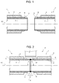
Figures 1 and 2 show sections, with parts removed for clarity, of pipe sections at various joining stages; -
Figures 3 and 4 show larger-scale sections, with parts removed for clarity, of pipe sections at various stages in the method according to the present invention; -
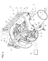
Figure 5 shows a view in perspective, with parts removed for clarity, of the device for applying protective sheeting of polymer material according to the present invention; -
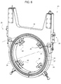
Figure 6 shows a larger-scale side view, with parts removed for clarity, of a component part of theFigure 5 device; -
Figures 7 and8 show larger-scale views in perspective, with parts removed for clarity, of a carriage of theFigure 5 device; -
Figure 9 shows a view in perspective, with parts removed for clarity, of a detail of the device; -
Figure 10 shows a schematic of the control system of theFigure 5 device; -
Figures 11-14 show schematics, with parts removed for clarity, of an operating sequence of theFigure 5 device. -
Numbers 1 inFigure 1 indicate two pipe sections, each of which comprises ametal cylinder 2; afirst coating 3 of polymer material, normally polyethylene or polypropylene, contacting and forcorrosionproofing metal cylinder 2; and asecond coating 4 of Gunite or concrete for ballast. - In an alternative embodiment not shown, the pipe sections have no second coating.
- Each
pipe section 1 has two opposite free ends 5 (only one shown inFigures 1 and 2 ) with nofirst coating 3 orsecond coating 4.First coating 3 has abevel 6 at eachfree end 5. Twosuccessive pipe sections 1, aligned along a longitudinal axis A1 (Figure 1 ), are positioned withfree ends 5 together, parallel and facing each other, and are welded, possibly in a number of passes at successive work stations, to form anannular weld bead 7 in between (Figure 2 ). As shown inFigure 2 , the twowelded pipe sections 1 form acutback 8 extending along longitudinal axis A1, betweenbevels 6 onfirst coating 3, and alongannular weld bead 7. - When joined,
pipe sections 1 form a pipeline indicated generically by P, and which, in the present description, also includes the pipeline being constructed and formed, for example, by only two joinedpipe sections 1. - In addition to
welding metal cylinders 2, joiningpipe sections 1 also comprises restoringfirst coating 3 and possibly alsosecond coating 4. Restoringfirst coating 3 comprises grit-blasting the surface ofcutback 8;induction heating cutback 8 to roughly 250°C; and applying in rapid succession onto cutback 8 afirst coat 9,second coat 10, andthird coat 11 of polymer material (Figure 3 ). - As shown in
Figure 3 ,first coat 9 is a 100-500 micron thick coat of epoxy resin (FBE - fusion bonded epoxy) sprayed in powdered form ontocutback 8 using a spray gun not shown.Second coat 10 is a 100-500 micron thick coat of modified copolymer, normally CMPE or CMPP, sprayed in powdered form on top offirst coat 9 oncutback 8 using a spray gun not shown. Andthird coat 11 is a 2-5 mm thick coat of polymer, preferably polyolefin, CMPE or CMPP, applied by winding a single piece ofprotective sheeting 12 of polymer material aboutcutback 8 at awork station 13, as shown inFigure 5 . In the example shown,protective sheeting 12 is wound aboutcutback 8 at station 13 (Figure 5 ), is wider than cutback 8 (measured along longitudinal axis A1 -Figure 2 ) so as to overlapfirst coatings 3 andbevels 6 of both joinedpipe sections 1, and is long enough to wind completely aboutcutback 8 and overlap at the ends. -
Protective sheeting 12 is actually extruded as it is wound about pipeline P. - With reference to
Figure 4 ,second coating 4 is restored with a coat of cement C. -
Number 14 inFigure 5 indicates a device for plastifying the polymer material from whichprotective sheeting 12 is made, and for extruding and simultaneously windingprotective sheeting 12 about pipeline P. - Constructing pipeline P, in particular on board a laying vessel (not shown), comprises feeding pipeline P in steps in a direction D1 parallel to longitudinal axis A1; and fixing
device 14 to pipeline P atcutback 8.Device 14 is located atwork station 13, and comprises aframe 15; acarriage 16 movable alongframe 15; a plastifying andextrusion assembly 17 mounted oncarriage 16; arolling assembly 18 mounted oncarriage 16; ahopper 19 for feeding solid polymer material to plastifying andextrusion assembly 17; and acontrol unit 20 connected tocarriage 16.Frame 15 comprises two facinggrippers 21 spaced apart; and beams 22 for rigidly connectinggrippers 21. Eachgripper 21 is annular, and has onesector 23 and twosectors 24 complementary with one another to define a ring.Sectors 23 ofgrippers 21 are connected rigidly to one another bybeams 22; and the twosectors 24 of eachgripper 21 are hinged tocorresponding sector 23 about hinge axes parallel to longitudinal axis A1, and are operated byactuators 25 to rotate from the closed position inFigure 6 to an open position (not shown) to releasedevice 14 frompipeline P. Sectors adjustable spacers 26 facing and designed to be positioned contacting pipeline P, and which are adjusted accurately tocentre frame 15 on pipeline P. - As shown in
Figure 6 , in the closed position,sectors gripper 21 define acircular guide 27 for carriage 16 (Figure 5 ); and acircular rack 28 which cooperates with carriage 16 (Figure 5 ) to move it forward. - As shown in
Figure 5 ,frame 15 is designed to selectively connectdevice 14 to pipeline P; tocentre guides 27 with respect to longitudinal axis A1 of pipeline P; and to support and guidecarriage 16 along an annular path. - As shown in
Figures 7 and8 ,carriage 16 comprises twoactuators 29 for movingcarriage 16 forward; two facing, sector-shaped plates 30; and twobeams 31 connecting facingplates 30. The outer face of eachplate 30 is fitted withrollers 32 for engaging guide 27 (Figure 6 ); and apinion 33 operated byrespective actuator 29 and designed to engage rack 28 (Figure 6 ) to movecarriage 16 along the annular path about pipeline P (Figure 5 ).Carriage 16, in fact, serves to support and move plastifying andextrusion assembly 17 and rollingassembly 18 about pipeline P (Figure 5 ). - As shown in
Figure 9 , plastifying andextrusion assembly 17 comprises aplastifying device 34, astorage tank 35, and anextrusion head 36, which, in the preferred embodiment of the invention, form a single rigid block mounted oncarriage 16, betweenplates 30, to rotate about an axis A2 parallel to longitudinal axis A1 (Figure 7 ), to adjust the position ofextrusion head 36 with respect to pipeline P (Figure 5 ). For this purpose, as shown inFigure 7 , plastifying andextrusion assembly 17 is connected tocarriage 16 by anactuator 37 for accurately adjusting the position of plastifying andextrusion assembly 17 about axis A2. - As shown in
Figure 9 ,plastifying device 34 is a screw type driven by amotor 38 andreducer 39, and comprises acylinder 40, in turn comprising aportion 43, and aportion 41 with afeed port 42.Portion 41 is preferably cooled by a water circuit, andportion 43 is preferably heated by electric resistors.Cylinder 40 is connected by a U-fitting tostorage tank 35, which comprises achamber 44, preferably a cylinder, in which apiston 45 is operated by a preferablyelectromagnetic drive 46 to alter the volume ofstorage tank 35. The rod (not shown) ofpiston 45 is preferably defined by a screw operated by a helical gear (not shown). - To reduce its size and weight,
plastifying device 34 is designed to supply a maximum amount of soft polymer material smaller than the maximum capacity ofextrusion head 36. -
Extrusion head 36 comprises a slit-shapedextrusion port 47 designed to formprotective sheeting 12 of the required width and thickness, and is connected directly tostorage tank 35. Plastifying andextrusion assembly 17 also comprises ablade 48 fitted toextrusion port 47 ofextrusion head 36 to selectively cut the extrudedprotective sheeting 12, and which is operated by anactuator 49 fitted toextrusion head 36, and also serves to closeextrusion port 47 to prevent the soft polymer material from dripping. - As shown in
Figures 7 and8 , rollingassembly 18 is fitted tocarriage 16, and comprises aroller 50; a supportingstructure 51 fitted adjustably tocarriage 16; an articulatedlink 52, in particular an articulated quadrilateral, connectingroller 50 to supportingstructure 51; and anactuator 53 between articulatedlink 52 and supportingstructure 51. Supportingstructure 51 provides for accurately adjusting the position of the whole of rollingassembly 18 with respect tocarriage 16. - As shown in
Figure 8 , rollingassembly 18 comprises anactuator 54 fitted to the articulated link; and atransmission 55 for connectingactuator 54 toroller 50, androtating roller 50 at selectively adjustable speeds and in opposite directions.Roller 50 is made of rigid material, preferably metal, and has a contoured profile substantially defined by acentral portion 56 designed to contactcutback 8, and by two smaller-diameter lateral portions 57 designed to contactprotective sheeting 12 atcoating 3.Roller 50 has a contouredgroove 58 formed incentral portion 56 to adapt the roller to the shape of annular weld bead 7 (Figure 3 ). - As shown in
Figure 5 ,hopper 19 is located overdevice 14, and is connectable selectively to feedport 42 to feed the solid, preferably granular, polymer material toplastifying device 34 whencarriage 16 is in a rest position over pipeline P. - As shown in
Figure 10 ,control unit 20 is connected to actuators 25 to selectively open andclose sectors 24; to actuators 29 to movecarriage 16 along the annular path; to actuator 37 to adjust the tilt of plastifying andextrusion assembly 17; tomotor 38 for drivingplastifying device 38; to drive 46 ofpiston 45; to actuator 49 ofblade 48; to actuator 53 for adjusting the position ofroller 50; and to actuator 54 for rotatingroller 50. -
Control unit 20 is also connected to thermocouples TC fitted to the whole of plastifying andextrusion assembly 17 to keep the soft polymer material at the temperatures required to plastify and feed it toextrusion port 47; and to temperature sensors T and pressure sensors P fitted to plastifying andextrusion assembly 17 to determine the condition of the soft polymer material and adjust thermocouples TC accordingly. - As shown in
Figure 5 ,carriage 16 is connected to acable bundle 59, which comprises signal cables, power cables, compressed-air feed pipes, and cooling circuit pipes for coolingfeed port 42. - With reference to
Figure 5 , in actual use, pipeline P, when released fromdevice 14, moves one step forward with respect todevice 14 in direction D1 parallel to longitudinal axis A1. At this stage,carriage 16 is in the rest position over pipeline P, and the hopper feeds the polymer material toplastifying device 34, which plastifies and feeds it tostorage tank 35. Moving pipeline P forward takes much longer than to extrude and applyprotective sheeting 12, so the time allotted to plastify the polymer material is long enough to employ a relativelysmall plastifying device 34 to plastify enough polymer material forprotective sheeting 12. Next,device 14 is clamped to pipeline P, withextrusion head 36 positioned over cutback 8 (Figure 2 ). - With reference to
Figure 11 , in the rest position,extrusion port 47 is located to one side, in an upper quadrant of the annular path, androller 50 is located a given distance from pipeline P. At the initial extrusion stage,carriage 16, i.e.extrusion head 36, is maintained stationary in the rest position, and a first portion ofprotective sheeting 12 is extruded and drops freely by gravity into a position between pipeline P androller 50. With reference toFigure 12 , when the first portion ofprotective sheeting 12 is located between pipeline P androller 50,roller 50 is activated to press it against pipeline P. At this point,carriage 16, i.e.extrusion head 36, can start moving along the annular path, so infeed of the solid polymer material is cut off, and plastification continues as long as there is polymer material insideplastifying device 34. - With reference to
Figure 13 , ascarriage 16 moves forward, extrusion ofprotective sheeting 12 continues by gradually expelling the soft polymer material fromstorage tank 35 throughextrusion head 36 andextrusion port 47.Roller 50 is moved in time withcarriage 16, so as to roll over and pressprotective sheeting 12 onto pipeline P without generating shear stress inprotective sheeting 12, which is still soft when applied. The speed ofpiston 45 is also synchronized with the speed ofcarriage 16 to formprotective sheeting 12 of constant thickness. At this stage, theprotective sheeting 12 being extruded is kept substantially taut between the extrusion port and the grip point betweenroller 50 and pipeline P, so thatprotective sheeting 12 is pressed firmly onto pipeline P to prevent air being trapped between the pipeline andprotective sheeting 12, and which would be hard to expel onceprotective sheeting 12 is applied. - Particularly effective is adjusting the travelling speed of
carriage 16, and therefore the speed ofpiston 45 and the rolling speed ofroller 50, as a function of the position ofcarriage 16. In fact, the speed with whichprotective sheeting 12 is applied is affected by two factors connected with the position ofcarriage 16 and therefore ofprotective sheeting 12 itself : the force of gravity onprotective sheeting 12 issuing fromextrusion port 47; and the fragile nature of the softprotective sheeting 12. The position ofextrusion port 47 with respect to pipeline P therefore affects the form ofprotective sheeting 12, andcarriage 16 must be accelerated or decelerated at given points along the annular path. This variation in speed may conveniently be programmed, for example, by dividing the path into sectors and assigning each a given travelling speed. - For the same reasons, and to prevent
protective sheeting 12 from contacting pipeline P downstream from the grip point byroller 50, the distance betweenextrusion port 47 and pipeline P when applyingprotective sheeting 12 is conveniently adjusted as a function of the position ofcarriage 16. - Given the width of
protective sheeting 12, one turn ofcarriage 16 about pipeline P is enough to restore first coating 3 (Figure 3 ). In actual fact,carriage 16 travels over 360° to allowroller 50 to compress and possibly overlap the opposite ends ofprotective sheeting 12 as shown inFigure 14 . - With reference to
Figure 14 , once extruded,protective sheeting 12 is cut byblade 48, which closesextrusion port 47 to prevent the soft polymer material from dripping. - At this point,
carriage 16 is returned to the initial rest position (Figure 11 ), travelling along the annular path in the opposite direction (clockwise inFigure 14 ) to that travelled when applyingprotective sheeting 12. At this stage,roller 50 is kept pressed againstprotective sheeting 12 and rolled in the opposite direction. - When
carriage 16 reaches the initial rest position,device 14 is released from pipeline P to allow it to move freely with respect todevice 14; and plastifying andextrusion assembly 17 is ready to start the next cycle. - The advantages of the method as described and illustrated are obvious.
- Clearly, changes may be made to the preferred embodiment described of the present invention without, however, departing from the protective scope of the accompanying Claims.
Claims (11)
- A method of applying protective sheeting of polymer material to a pipeline, the method comprising the steps of advancing a carriage (16) along an annular path extending about the longitudinal axis (A1) of the pipeline (P); extruding the protective sheeting (12) on the carriage (16); winding the protective sheeting (12), as it is extruded, about a cutback (8) on the pipeline (P); selectively gripping and releasing a frame (15) about the pipeline (P) by means of two facing and spaced apart grippers (21), which defines respective guides (27) for the carriage (16), in order to selectively connect device (14) to pipeline (P), to centre guides (27) with respect to longitudinal axis (A1) of pipeline (P), and to support and guide carriage (16) along an annular path.
- The method as claimed in claim 1, wherein each gripper (21) comprises one sector (23) and two further sectors (24), which are hinged to sector (23) about hinge axes parallel to longitudinal axis (A1), complementary with one another to define a ring; the method comprising the step of rotating the further sectors (24) by means of actuators (25) between a closed position and an open position to grip and release device (14) from pipeline (P), wherein in the closed position, the sector (23) and the further sectors (23, 24) of each gripper (21) define the circular guide (27) for guiding the carriage (16).
- The method as claimed in Claim 1 or 2, further comprising the step of centering frame (15) on pipeline (P) by means of adjustable spacers (26) which are mounted on grippers (21) and are designed to be positioned contacting pipeline (P).
- A method as claimed in any one of the foregoing Claims, wherein the step of extruding the protective sheeting (12) comprises extruding an initial portion of the protective sheeting (12) with the carriage (16) stationary and so positioned that the initial portion of the protective sheeting (12) is inserted by force of gravity between the pipeline (P) and a roller (50) for compressing the protective sheeting (12); and gripping the initial portion of the protective sheeting (12) between the roller (50) and the pipeline (P).
- A method as claimed in Claim 4, wherein the step of advancing the carriage (16) about the cutback (8) is activated when the initial portion of the protective sheeting (12) is gripped between the pipeline (P) and the roller (50).
- A method as claimed in any one of the foregoing Claims, and comprising the steps of cutting the protective sheeting (12) at an extrusion port (47) upon completion of the extrusion step.
- A device for applying protective sheeting of polymer material to a pipeline, the device (14) comprising a carriage (16), which moves along an annular path extending about the longitudinal axis (A1) of the pipeline (P) to extrude and apply the protective sheeting (12) to a cutback (8) on the pipeline (P); and a frame (15) comprising two facing and spaced apart grippers (21), each, having one sector (23) and two further sectors (24), which are hinged to sector (23) about hinge axes parallel to longitudinal axis (A1), complementary with one another to define a ring, and are operated by actuators (25) to rotate between a closed position and an open position to grip and release device (14) from pipeline (P), wherein in the closed position, the sector (23) and the further sectors (23, 24) of each gripper (21) define a circular guide (27) for guiding the carriage (16).
- The device as claimed in claim 7, wherein the carriage (16) comprise two facing, sector-shaped plates (30); and two beams (31) connecting facing plates (30); the outer face of each plate (30) being fitted with rollers (32) for engaging guide (27).
- The device as claimed in claim 8, wherein the sector (23) and the further sectors (23, 24) of each gripper (21) define a circular rack (28) which cooperates with carriage (16) to move the carriage (16) forward.
- The device as claimed in claim 9, wherein the outer face of each plate (30) is fitted with rollers (32) for engaging guide (27) and a pinion (33) operated by respective actuator (29) and designed to engage rack (28) to move carriage (16) along the annular path about pipeline (P).
- The device as claimed in any one of the foregoing Claims, wherein sectors (23) and further sectors (24) have adjustable spacers (26) facing and designed to be positioned contacting pipeline (P), and which are adjusted accurately to centre frame (15) on pipeline (P).
Applications Claiming Priority (2)
| Application Number | Priority Date | Filing Date | Title |
|---|---|---|---|
| IT001104A ITMI20111104A1 (en) | 2011-06-17 | 2011-06-17 | METHOD AND EQUIPMENT TO APPLY A PROTECTIVE SHEET OF POLYMERIC MATERIAL WITH A PIPE |
| EP12169896.3A EP2535168B2 (en) | 2011-06-17 | 2012-05-29 | Method and device for applying protective sheeting of polymer material to a pipeline |
Related Parent Applications (2)
| Application Number | Title | Priority Date | Filing Date |
|---|---|---|---|
| EP12169896.3A Division EP2535168B2 (en) | 2011-06-17 | 2012-05-29 | Method and device for applying protective sheeting of polymer material to a pipeline |
| EP12169896.3A Division-Into EP2535168B2 (en) | 2011-06-17 | 2012-05-29 | Method and device for applying protective sheeting of polymer material to a pipeline |
Publications (1)
| Publication Number | Publication Date |
|---|---|
| EP2700490A1 true EP2700490A1 (en) | 2014-02-26 |
Family
ID=44534536
Family Applications (2)
| Application Number | Title | Priority Date | Filing Date |
|---|---|---|---|
| EP12169896.3A Active EP2535168B2 (en) | 2011-06-17 | 2012-05-29 | Method and device for applying protective sheeting of polymer material to a pipeline |
| EP13193390.5A Withdrawn EP2700490A1 (en) | 2011-06-17 | 2012-05-29 | Method and device for applying protective sheeting of polymer material to a pipeline |
Family Applications Before (1)
| Application Number | Title | Priority Date | Filing Date |
|---|---|---|---|
| EP12169896.3A Active EP2535168B2 (en) | 2011-06-17 | 2012-05-29 | Method and device for applying protective sheeting of polymer material to a pipeline |
Country Status (7)
| Country | Link |
|---|---|
| US (1) | US9956583B2 (en) |
| EP (2) | EP2535168B2 (en) |
| AU (1) | AU2012270042B2 (en) |
| BR (1) | BR112013032329B1 (en) |
| IT (1) | ITMI20111104A1 (en) |
| RU (1) | RU2593619C2 (en) |
| WO (1) | WO2012172451A1 (en) |
Families Citing this family (18)
| Publication number | Priority date | Publication date | Assignee | Title |
|---|---|---|---|---|
| GB2533645B (en) | 2014-12-24 | 2017-09-20 | Subsea 7 Ltd | Insulating inserts for field joints of coated rigid pipelines |
| ITMI20121679A1 (en) * | 2012-10-08 | 2014-04-09 | Saipem Spa | METHOD, APPARATUS AND WORK STATION TO APPLY A PROTECTIVE SHEET OF POLYMERIC MATERIAL TO A PIPE AND PROGRAM FOR PROCESSING TO PERFORM THE METHOD |
| FI125036B (en) * | 2013-06-20 | 2015-04-30 | Uponor Infra Oy | Device for carrying out extrusion and connecting means for forming a supply pipe |
| ITMI20131777A1 (en) * | 2013-10-24 | 2015-04-25 | Saipem Spa | METHOD AND DEVICE FOR APPLYING A PROTECTIVE SHEET OF POLYMERIC MATERIAL WITH A PIPE |
| GB2520717B (en) | 2013-11-28 | 2016-04-06 | Subsea 7 Ltd | Techniques for coating pipeline field joints |
| ITMI20132004A1 (en) * | 2013-11-29 | 2015-05-30 | Saipem Spa | EQUIPMENT, WORK STATION AND METHOD TO APPLY A PROTECTIVE SHEET OF POLYMERIC MATERIAL TO A PIPE AND PROGRAM FOR PROCESSING TO IMPLEMENT THE METHOD |
| GB2520769B (en) | 2013-12-02 | 2016-03-09 | Subsea 7 Ltd | Techniques for coating pipeline field joints |
| ITUB20152638A1 (en) * | 2015-07-30 | 2017-01-30 | Saipem Spa | EQUIPMENT AND METHOD FOR COATING TUBES |
| WO2017208279A1 (en) * | 2016-05-31 | 2017-12-07 | 川崎重工業株式会社 | Pipe-covering member, pipe-covering method and pipe-covering equipment |
| CN106363901B (en) * | 2016-08-28 | 2018-06-29 | 河南新开源石化管道有限公司 | A kind of pyrocondensation adhesive tape winding method for bend pipe |
| CN106182732B (en) * | 2016-08-28 | 2018-08-07 | 河南新开源石化管道有限公司 | A kind of bend pipe wind with three sections of heating functions |
| WO2018081554A1 (en) * | 2016-10-27 | 2018-05-03 | North Carolina State University | 3d printing of fibrous structures |
| WO2018148831A1 (en) * | 2017-02-17 | 2018-08-23 | Automatic Coating Limited | Girth weld coater |
| CN110239109B (en) * | 2018-03-07 | 2024-03-22 | 临海伟星新型建材有限公司 | Equipment and method for inspecting welding line quality of polyethylene pipe fitting |
| EP3847003B1 (en) | 2018-09-07 | 2024-03-06 | Saipem S.p.A. | Machine and method for making a protective joint about an annular junction portion of a pipeline |
| KR102595928B1 (en) | 2018-09-28 | 2023-10-31 | 삼성디스플레이 주식회사 | Laminating roller, laminating device and method of laminating display apparatus |
| GB2581469A (en) * | 2018-11-16 | 2020-08-26 | Pipeline Technique Ltd | Tape winding apparatus and method |
| GB2581358B (en) * | 2019-02-13 | 2021-10-27 | Ridgway Machines Ltd | Pipe consolidation apparatus and method |
Citations (3)
| Publication number | Priority date | Publication date | Assignee | Title |
|---|---|---|---|---|
| WO2008071773A2 (en) * | 2006-12-14 | 2008-06-19 | Saipem S.P.A. | Pipe-joining method and apparatus for producing underwater pipelines, and underwater-pipeline-laying vessel comprising such an apparatus |
| WO2008107759A1 (en) * | 2007-03-02 | 2008-09-12 | Saipem S.P.A. | Method and apparatus for forming a protective coat about a cutback between pipes forming part of an underwater pipeline, and underwater-pipeline-laying vessel comprising such an apparatus |
| WO2010049353A1 (en) * | 2008-10-29 | 2010-05-06 | Oy Kwh Pipe Ab | Method and apparatus for coating pipes and pipe sections |
Family Cites Families (7)
| Publication number | Priority date | Publication date | Assignee | Title |
|---|---|---|---|---|
| US5520734A (en) * | 1989-07-17 | 1996-05-28 | Crc-Evans Rehabilitation Systems, Inc. | High pressure water jet cleaner and coating applicator |
| JP3001323B2 (en) † | 1992-02-14 | 2000-01-24 | 株式会社日本製鋼所 | Extrusion molding method and apparatus for multilayer parison |
| DE20321240U1 (en) † | 2003-12-22 | 2006-08-03 | Drossbach Gmbh & Co. Kg | Device for applying a reinforcement to a plastic pipe |
| DE602007013361D1 (en) * | 2007-04-25 | 2011-05-05 | Borealis Tech Oy | Method and device for coating pipes |
| US8334005B2 (en) * | 2008-11-14 | 2012-12-18 | Kraft Foods Global Brands Llc | Ribbon cutter apparatus and method for making sandwich baked goods |
| EP2298531A1 (en) | 2009-09-17 | 2011-03-23 | Oy KWH Pipe AB | Apparatus and method for coating pipes or pipe sections |
| WO2011137161A1 (en) * | 2010-04-27 | 2011-11-03 | Subsea Services International, Inc. | Pipe joint coating |
-
2011
- 2011-06-17 IT IT001104A patent/ITMI20111104A1/en unknown
-
2012
- 2012-05-29 EP EP12169896.3A patent/EP2535168B2/en active Active
- 2012-05-29 EP EP13193390.5A patent/EP2700490A1/en not_active Withdrawn
- 2012-05-31 US US14/126,360 patent/US9956583B2/en active Active
- 2012-05-31 BR BR112013032329-9A patent/BR112013032329B1/en active IP Right Grant
- 2012-05-31 AU AU2012270042A patent/AU2012270042B2/en active Active
- 2012-05-31 WO PCT/IB2012/052758 patent/WO2012172451A1/en not_active Ceased
- 2012-05-31 RU RU2013157182/05A patent/RU2593619C2/en not_active IP Right Cessation
Patent Citations (3)
| Publication number | Priority date | Publication date | Assignee | Title |
|---|---|---|---|---|
| WO2008071773A2 (en) * | 2006-12-14 | 2008-06-19 | Saipem S.P.A. | Pipe-joining method and apparatus for producing underwater pipelines, and underwater-pipeline-laying vessel comprising such an apparatus |
| WO2008107759A1 (en) * | 2007-03-02 | 2008-09-12 | Saipem S.P.A. | Method and apparatus for forming a protective coat about a cutback between pipes forming part of an underwater pipeline, and underwater-pipeline-laying vessel comprising such an apparatus |
| WO2010049353A1 (en) * | 2008-10-29 | 2010-05-06 | Oy Kwh Pipe Ab | Method and apparatus for coating pipes and pipe sections |
Also Published As
| Publication number | Publication date |
|---|---|
| US20140154409A1 (en) | 2014-06-05 |
| EP2535168B1 (en) | 2013-11-20 |
| EP2535168A1 (en) | 2012-12-19 |
| ITMI20111104A1 (en) | 2012-12-18 |
| AU2012270042B2 (en) | 2017-06-01 |
| US9956583B2 (en) | 2018-05-01 |
| AU2012270042A1 (en) | 2014-01-16 |
| BR112013032329A2 (en) | 2016-12-20 |
| BR112013032329B1 (en) | 2020-10-27 |
| RU2013157182A (en) | 2015-07-27 |
| EP2535168B2 (en) | 2016-11-30 |
| RU2593619C2 (en) | 2016-08-10 |
| WO2012172451A1 (en) | 2012-12-20 |
Similar Documents
| Publication | Publication Date | Title |
|---|---|---|
| EP2700490A1 (en) | Method and device for applying protective sheeting of polymer material to a pipeline | |
| EP2535629B1 (en) | Pipe-joining method and apparatus for producing underwater pipelines, and underwater-pipeline-laying vessel comprising such an apparatus | |
| EP2903799B1 (en) | Method, device and work station for applying protective sheeting of polymer material to a pipeline, and computer program for implementing such a method | |
| EP3074687B1 (en) | Apparatus and method for applying protective sheeting of polymer material to a pipeline | |
| US20210323018A1 (en) | Machine and method for making a protective joint about an annular junction portion of a pipeline |
Legal Events
| Date | Code | Title | Description |
|---|---|---|---|
| PUAI | Public reference made under article 153(3) epc to a published international application that has entered the european phase |
Free format text: ORIGINAL CODE: 0009012 |
|
| AC | Divisional application: reference to earlier application |
Ref document number: 2535168 Country of ref document: EP Kind code of ref document: P |
|
| AK | Designated contracting states |
Kind code of ref document: A1 Designated state(s): AL AT BE BG CH CY CZ DE DK EE ES FI FR GB GR HR HU IE IS IT LI LT LU LV MC MK MT NL NO PL PT RO RS SE SI SK SM TR |
|
| 17P | Request for examination filed |
Effective date: 20140818 |
|
| RBV | Designated contracting states (corrected) |
Designated state(s): AL AT BE BG CH CY CZ DE DK EE ES FI FR GB GR HR HU IE IS IT LI LT LU LV MC MK MT NL NO PL PT RO RS SE SI SK SM TR |
|
| 17Q | First examination report despatched |
Effective date: 20150122 |
|
| GRAP | Despatch of communication of intention to grant a patent |
Free format text: ORIGINAL CODE: EPIDOSNIGR1 |
|
| RIC1 | Information provided on ipc code assigned before grant |
Ipc: F16L 13/02 20060101ALN20160418BHEP Ipc: B29C 47/02 20060101ALN20160418BHEP Ipc: B29C 63/06 20060101AFI20160418BHEP |
|
| INTG | Intention to grant announced |
Effective date: 20160504 |
|
| STAA | Information on the status of an ep patent application or granted ep patent |
Free format text: STATUS: THE APPLICATION IS DEEMED TO BE WITHDRAWN |
|
| 18D | Application deemed to be withdrawn |
Effective date: 20160915 |