EP2700354B1 - Drainage-Steuersystem sowie Drainagesystem mit einem derartigen Drainage-Steuersystem - Google Patents
Drainage-Steuersystem sowie Drainagesystem mit einem derartigen Drainage-Steuersystem Download PDFInfo
- Publication number
- EP2700354B1 EP2700354B1 EP13173490.7A EP13173490A EP2700354B1 EP 2700354 B1 EP2700354 B1 EP 2700354B1 EP 13173490 A EP13173490 A EP 13173490A EP 2700354 B1 EP2700354 B1 EP 2700354B1
- Authority
- EP
- European Patent Office
- Prior art keywords
- drainage
- pressure
- unit
- control system
- waveform
- Prior art date
- Legal status (The legal status is an assumption and is not a legal conclusion. Google has not performed a legal analysis and makes no representation as to the accuracy of the status listed.)
- Not-in-force
Links
- 238000004458 analytical method Methods 0.000 claims description 34
- 238000007917 intracranial administration Methods 0.000 claims description 32
- 230000007274 generation of a signal involved in cell-cell signaling Effects 0.000 claims description 15
- 238000004891 communication Methods 0.000 claims description 14
- 238000011156 evaluation Methods 0.000 claims description 14
- 210000004289 cerebral ventricle Anatomy 0.000 claims description 5
- 238000000605 extraction Methods 0.000 claims description 5
- 239000007788 liquid Substances 0.000 claims description 4
- 230000002490 cerebral effect Effects 0.000 claims description 3
- 238000001514 detection method Methods 0.000 claims description 3
- 238000005259 measurement Methods 0.000 claims description 3
- 230000001360 synchronised effect Effects 0.000 claims description 3
- 238000010972 statistical evaluation Methods 0.000 claims description 2
- 210000004556 brain Anatomy 0.000 description 17
- 210000001175 cerebrospinal fluid Anatomy 0.000 description 6
- 239000012530 fluid Substances 0.000 description 6
- 230000000875 corresponding effect Effects 0.000 description 5
- 238000001802 infusion Methods 0.000 description 4
- 238000012544 monitoring process Methods 0.000 description 3
- 230000002123 temporal effect Effects 0.000 description 3
- 210000000683 abdominal cavity Anatomy 0.000 description 2
- 239000007943 implant Substances 0.000 description 2
- 230000003187 abdominal effect Effects 0.000 description 1
- 238000005452 bending Methods 0.000 description 1
- 238000009530 blood pressure measurement Methods 0.000 description 1
- 230000001276 controlling effect Effects 0.000 description 1
- 238000012937 correction Methods 0.000 description 1
- 230000002596 correlated effect Effects 0.000 description 1
- 238000011157 data evaluation Methods 0.000 description 1
- 230000003247 decreasing effect Effects 0.000 description 1
- 230000001419 dependent effect Effects 0.000 description 1
- 238000010586 diagram Methods 0.000 description 1
- 238000007599 discharging Methods 0.000 description 1
- 239000003814 drug Substances 0.000 description 1
- 208000003906 hydrocephalus Diseases 0.000 description 1
- 238000000034 method Methods 0.000 description 1
- 230000004044 response Effects 0.000 description 1
- 238000005070 sampling Methods 0.000 description 1
- 238000012360 testing method Methods 0.000 description 1
Images


Classifications
-
- A—HUMAN NECESSITIES
- A61—MEDICAL OR VETERINARY SCIENCE; HYGIENE
- A61B—DIAGNOSIS; SURGERY; IDENTIFICATION
- A61B5/00—Measuring for diagnostic purposes; Identification of persons
- A61B5/03—Measuring fluid pressure within the body other than blood pressure, e.g. cerebral pressure ; Measuring pressure in body tissues or organs
- A61B5/031—Intracranial pressure
-
- A—HUMAN NECESSITIES
- A61—MEDICAL OR VETERINARY SCIENCE; HYGIENE
- A61B—DIAGNOSIS; SURGERY; IDENTIFICATION
- A61B5/00—Measuring for diagnostic purposes; Identification of persons
- A61B5/02—Detecting, measuring or recording for evaluating the cardiovascular system, e.g. pulse, heart rate, blood pressure or blood flow
- A61B5/024—Measuring pulse rate or heart rate
-
- A—HUMAN NECESSITIES
- A61—MEDICAL OR VETERINARY SCIENCE; HYGIENE
- A61B—DIAGNOSIS; SURGERY; IDENTIFICATION
- A61B5/00—Measuring for diagnostic purposes; Identification of persons
- A61B5/72—Signal processing specially adapted for physiological signals or for diagnostic purposes
- A61B5/7235—Details of waveform analysis
- A61B5/7246—Details of waveform analysis using correlation, e.g. template matching or determination of similarity
-
- A—HUMAN NECESSITIES
- A61—MEDICAL OR VETERINARY SCIENCE; HYGIENE
- A61M—DEVICES FOR INTRODUCING MEDIA INTO, OR ONTO, THE BODY; DEVICES FOR TRANSDUCING BODY MEDIA OR FOR TAKING MEDIA FROM THE BODY; DEVICES FOR PRODUCING OR ENDING SLEEP OR STUPOR
- A61M27/00—Drainage appliance for wounds or the like, i.e. wound drains, implanted drains
- A61M27/002—Implant devices for drainage of body fluids from one part of the body to another
- A61M27/006—Cerebrospinal drainage; Accessories therefor, e.g. valves
-
- A—HUMAN NECESSITIES
- A61—MEDICAL OR VETERINARY SCIENCE; HYGIENE
- A61B—DIAGNOSIS; SURGERY; IDENTIFICATION
- A61B5/00—Measuring for diagnostic purposes; Identification of persons
- A61B5/103—Measuring devices for testing the shape, pattern, colour, size or movement of the body or parts thereof, for diagnostic purposes
- A61B5/11—Measuring movement of the entire body or parts thereof, e.g. head or hand tremor or mobility of a limb
- A61B5/1116—Determining posture transitions
-
- A—HUMAN NECESSITIES
- A61—MEDICAL OR VETERINARY SCIENCE; HYGIENE
- A61B—DIAGNOSIS; SURGERY; IDENTIFICATION
- A61B5/00—Measuring for diagnostic purposes; Identification of persons
- A61B5/68—Arrangements of detecting, measuring or recording means, e.g. sensors, in relation to patient
- A61B5/6846—Arrangements of detecting, measuring or recording means, e.g. sensors, in relation to patient specially adapted to be brought in contact with an internal body part, i.e. invasive
- A61B5/6847—Arrangements of detecting, measuring or recording means, e.g. sensors, in relation to patient specially adapted to be brought in contact with an internal body part, i.e. invasive mounted on an invasive device
- A61B5/6852—Catheters
-
- A—HUMAN NECESSITIES
- A61—MEDICAL OR VETERINARY SCIENCE; HYGIENE
- A61B—DIAGNOSIS; SURGERY; IDENTIFICATION
- A61B5/00—Measuring for diagnostic purposes; Identification of persons
- A61B5/72—Signal processing specially adapted for physiological signals or for diagnostic purposes
- A61B5/7235—Details of waveform analysis
- A61B5/725—Details of waveform analysis using specific filters therefor, e.g. Kalman or adaptive filters
Definitions
- the invention relates to a drainage control system for generating control signal for a drainage device for use in a drainage line for guiding a fluid from a brain chamber of a patient. Furthermore, the invention relates to a drainage system with such a drainage control system.
- a drainage system with a valve as a drainage device for use in a drainage line for guiding a fluid from a brain chamber of a patient is known from EP 2 221 083 A and the US 6,248,080 B1 .
- Other drainage devices for the controlled discharge of brain fluid are known from the EP 0 982 048 A1 and the DE 196 43 782 C1 ,
- the drainage control system uses a pressure data sequence recorded in time-resolved manner by the pressure sensor and determines a duration, a phase and shape characteristics of a cranial pressure wave, which is correlated with the heartbeat and whose shape during a wave period in particular brain pressure-dependent. Waveform analysis associates the measured intracranial wave with waveform candidates.
- the drainage control system can be embodied as an implant and, in particular, compact in the form of a microchip.
- a pressure sensor according to claim 2 has proven itself in practice.
- a data acquisition unit represents a good compromise between accuracy of the measured data acquisition hardware requirements.
- Heart rate analysis by the heart rate analysis module may be accomplished by direct monitoring of a patient heart rate.
- an embodiment of the heart rate analysis module according to claim 4 is possible, in which the pressure data detected by the pressure sensor are used to determine the pulse rate. A separate direct monitoring of the pulse rate is then eliminated.
- a direct pulse frequency monitoring can be used to check a heart rate analysis value, which was obtained from the brain chamber internal pressure data acquired by the pressure sensor.
- a median filter according to claim 5 and a low-pass filter according to claim 6 have been found to be particularly suitable for heart rate analysis.
- a counting unit is an easily realizable component of the waveform analysis module.
- the waveform analysis can be done on the basis of the recorded number of pressure maxima or on the basis of the recorded number of pressure minima of the cranial pressure wave. Alternatively or additionally, a relative pressure difference between successive pressure maxima or a time interval between successive pressure maxima for waveform analysis can be used.
- An amplitude, ie the pressure difference between a pressure minimum and a time-adjacent pressure maximum, can also be used as an alternative or in addition to the waveform analysis.
- An evaluation device according to claim 8 can be made very simple hardware and software.
- a position sensor according to claim 9 allows inclusion of a current patient position in a control signal generation for the drainage device. For example, in the case of a detected change in the patient's position from lying down to standing, an undesired overdrainage can be counteracted, in particular by a corresponding precontrol.
- a flow sensor according to claim 11 may be used to monitor a drainage quantity. Again, an undesirable overdrainage can be avoided.
- a pressure sensor which is in signal communication with the drainage device and the drainage control device, can be used to determine a condition of the patient by detecting a temporal change in intracranial pressure after a defined amount of cerebrospinal fluid has been removed from the cerebral cavity (elastance).
- a valve according to claim 13 and a pump according to claim 14 are preferred variants for the drainage device.
- FIG. 1 schematically shows a hydrocephalus patient.
- a medical drainage system 7 with a drainage device in the form of a valve 8 is arranged. The latter is used for targeted removal of liquor as an example of a liquid from the CSF space (brain chamber) 2.
- the drainage system 7 can be designed as an implant as a whole.
- Fig. 2 This includes a drainage control system 9 for control signal generation for the valve 8, a drainage control device 10 which is in signal communication with the drainage control system 9, and the valve 8 itself.
- the valve 8 may e.g. B. be executed on the type of valve, which is described in the EP 2 221 083 A or in the DE 196 43 782 C1 ,
- To the drainage control system 9 includes a pressure sensor 11 for time-resolved detection of an internal pressure in the brain chamber 2.
- the pressure sensor 11 is in signal communication with an evaluation device 12 of the drainage control system 9.
- the pressure sensor 11 is disposed in a tip of the proximal line section 4, which Brain catheter is executed.
- Part of the evaluation device 12 is a data acquisition unit 13 for detecting a print data sequence from the pressure sensor 11 during a Period between 3 seconds and 10 seconds.
- a sampling frequency of the data acquisition unit 13 may be at least 100 Hz.
- the data acquisition unit 13 measures the print data sequence for a period in the range of 5 seconds, for example, 5.12 seconds.
- the data acquisition unit 13 is designed as a datalogger.
- the pressure sensor 11 is directly in signal communication with the data acquisition unit 13.
- the evaluation device 12 includes a heart rate analysis module 14 for determining a patient heart rate from the pressure data sequence transmitted by the pressure sensor 11, a wave phase extraction module 15 for determining an initial time and an end point of a heart rate synchronous intracranial wave and a waveform analysis module 16 which maps a shape of the intracranial wave between the start and end timings of a particular waveform determined by the wave phase extraction module 15 among a plurality of waveform candidates.
- the waveform candidates are stored in a waveform candidate memory 17 of the drainage control system 9.
- the heart rate analysis module 14 includes a median filter 18 and a low pass filter 19.
- the median filter 18 and the low pass filter 19 are each a digital filter.
- the waveform analysis module 16 comprises a counting unit 20 for counting pressure maxima within an intracranial pressure wave detected by the pressure sensor 11 and extracted by the wave phase extraction module 15.
- the evaluation device 12 is embodied as a binary-operating digital computer such that pressure and / or time limit values which are used in the analysis, in particular in the modules 14, 15, 16, are selected as powers of two of respective limit reference values.
- the evaluation device 12 further includes a control signal generation module 21, which is in signal communication with the evaluation device 12.
- the control signal generation module 21 generates a drainage control signal on the basis of an assignment result of the waveform analysis module 16 of the evaluation device 12.
- the drainage control device 10 is in signal connection with the control signal generation module 21.
- the reciprocal of the patient heart rate determined by the heart rate analysis module 14 is a wave period of the intracranial pressure wave 22 (cf. Fig. 3 ), ie a period between the start time t A and the end time t E , which are determined in phase with the wave phase extraction module.
- a determination of the start time t A and the end time t E is made by comparing successive intracranial waves and determining a pressure minimum within the pressure data sequence of the intracranial wave 22, which determined in comparison to other pressure minima within the intracranial wave period Specifications are sufficient. These defaults may include, for example, discarding all pressure minima, according to which the pressure does not rise above a predetermined pressure limit. Another requirement may be a discard all pressure minima with too high absolute pressure value. Another requirement may be a rejection of pressure minima followed by a pressure minimum with too little absolute pressure.
- a waveform analysis in the waveform analysis module 16 is performed on the basis of a number of detected pressure maxima within a pressure data sequence of an in-phase determined intracranial wave. This waveform analysis is based on a relative pressure difference between successive pressure maxima and on a time interval between successive pressure maxima.
- the correspondence of the respectively measured print data sequence of a cranial pressure wave with the characteristics of the waveform candidates stored in the candidate memory 17 is checked.
- Fig. 3 shows a measured typical print data sequence. Shown is a pressure reading ICP (intracranial pressure, intracranial pressure) during a measurement period of about 1.6 s. Part of in the Fig. 2 illustrated print data sequence is the intracranial wave 22 with wave period T PW . The intracranial pressure wave 22 has five characteristic pressure maxima P 1 to P 5 which follow one another within the intracranial wave period T PW . Shown in the Fig. 3 is also the start time t A and the end time t E of the intracranial pressure wave 22, which occurs periodically synchronous to the heart rate.
- ICP intracranial pressure, intracranial pressure
- the initial time t A is determined by comparing successive intracranial waves 22 and by determining a pressure minimum p min , which satisfies the following requirements in comparison to other pressure minima between the maxima P 1 to P 5 :
- a pressure minimum p min which satisfies the following requirements in comparison to other pressure minima between the maxima P 1 to P 5 :
- This predetermined limit value is related to a wave amplitude of the respective intracranial pressure wave 22, ie to the difference between a maximum pressure value and a minimum pressure value of the intracranial pressure wave 22.
- This amplitude is also referred to as P wave amplitude.
- the predetermined limit over which the intracranial pressure must rise after the minimum p min can also amount to 25% of the P wave amplitude.
- the pressure minimum p min must be followed by another pressure minimum p min1 whose pressure value is significantly higher than the pressure value of the initial time pressure minimum p min .
- the end time t E is determined, in which all pressure minima at the end of a brain pressure wave 22, which exceed a certain pressure threshold, are discarded, since these are then assigned to a subsequent intracranial wave.
- the intracranial wave 22 evaluated with regard to its wave period and its phase is then determined with regard to its temporal form of an analysis. This will be explained below with reference to Fig. 4 described.
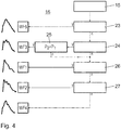
- the measured cranial pressure wave 22, for example, the one after Fig. 3 is compared with a total of five candidate values (types) WF i , which in the Fig. 4 with the numbers 1 to 5 are numbered.
- I inf represents an infusion rate, which in an infusion test, for example, with a size of 3 ml / min. the brain chamber 2 is added.
- the two derivatives of the temporal intracranial pressure ICP (t) in the formula represent an increase in the intracranial pressure during infusion on reaching a predetermined pressure value P o and a drop in the pressure value after the end of the infusion at the same pressure value P 0 .
- the five waveforms types 1 to 5 after Fig. 4 differ by the number, the relative height and the time sequence of the pressure maxima. In the waveform analysis, therefore, the number of pressure maxima, the relative pressure difference between successive pressure maxima and a time interval between successive pressure maxima P i are evaluated. This is done in the waveform analysis module 16.
- the print data sequence of an in-phase extracted brain pressure wave 22 is first analyzed with respect to the number of pressure maxima.
- a first query step 23 it is first checked whether exactly one maximum pressure exists. If yes ("y" in the Fig. 4 ), it is clear that the waveform is type 5. If no ("n" in the Fig. 4 In a further query step 24, a query is subsequently made as to whether the number of pressure maxima is greater than 2.
- a further inquiry step 25 queries whether the pressure value P 2 of the second pressure maximum lies within the measured intracranial pressure wave 22 is greater than the pressure value P 1 of the first pressure maximum. If yes, the waveform of the measured intracranial wave 22 corresponds to the candidate form type 3. If no or in the case that the interrogation step 24 gives the result "no", is queried in a further query step 26, whether the time interval between the first pressure maximum P 1 and a subsequent pressure maximum P 2 is greater than a predetermined limit, for example, greater than one-third of the entire wave period of the measured intracranial wave 22th If this is the case, the candidate type 1 is available. If no, the result of the query step 24 is used again. If the measured cranial pressure wave 22 has more than two pressure maxima, a waveform corresponding to the type 2 candidate form exists. If not, there is a waveform corresponding to the type 4 candidate form.
- a control signal for the valve control device 10 can then be generated by the control signal generation module 21.
- the valve 8 can then be opened, if it results from the assignment that a corresponding pressure scenario exists.
- the valve control system 9 may additionally have a position sensor 28 for detecting a position of the patient, as in the Fig. 2 indicated by dashed lines.
- the position sensor 28 is in signal communication with the control signal generation module 21.
- the position sensor 28 which may be constructed, for example, as position sensors, which are known from mobile phones, detects a position in particular a head of the patient and can decide whether it is standing, bending or lying.
- the control signal generation module 21 calculates a correction value for controlling the drainage control device 10.
- the drainage control system 9 may include a flow sensor 29 as shown in FIG Fig. 2 also indicated by dashed lines.
- the flow sensor 29 is also in signal communication with the control signal generation module 21.
- the flow sensor 29 measures a drainage flow of cerebrospinal fluid through the valve 8, that is, a quantity of liquor derived from the valve 8 per unit time during drainage. With the flow sensor 29, a maximum drainage amount per unit time can be limited, which avoids overdrainage.
- the flow sensor 29 outputs a corresponding signal to the control signal generation module 21 when a predefined drainage quantity limit value is reached.
- a pump may be used which, depending on the control by the drainage control device 10, actively promotes a predetermined amount of liquor via the liquor line 3 into the abdominal cavity 6.
- a predetermined drainage quantity is generated with the aid of the control signal generation module 21.
- a patient condition can be determined via a further parameter, the elastance E.
- a defined amount of drainage of CSF is removed from the brain chamber 2 in a short, defined period of time (so-called inverse bolus) and a resulting change in intracranial pressure ICP is determined.
Landscapes
- Health & Medical Sciences (AREA)
- Life Sciences & Earth Sciences (AREA)
- Engineering & Computer Science (AREA)
- Biomedical Technology (AREA)
- Veterinary Medicine (AREA)
- Public Health (AREA)
- General Health & Medical Sciences (AREA)
- Animal Behavior & Ethology (AREA)
- Heart & Thoracic Surgery (AREA)
- Molecular Biology (AREA)
- Biophysics (AREA)
- Physics & Mathematics (AREA)
- Medical Informatics (AREA)
- Pathology (AREA)
- Surgery (AREA)
- Hematology (AREA)
- Cardiology (AREA)
- Physiology (AREA)
- Signal Processing (AREA)
- Artificial Intelligence (AREA)
- Neurosurgery (AREA)
- Computer Vision & Pattern Recognition (AREA)
- Psychiatry (AREA)
- Neurology (AREA)
- Ophthalmology & Optometry (AREA)
- Otolaryngology (AREA)
- Anesthesiology (AREA)
- Measuring And Recording Apparatus For Diagnosis (AREA)
- External Artificial Organs (AREA)
Description
- Die Erfindung betrifft ein Drainage-Steuersystem zur Steuersignalerzeugung für eine Drainageeinrichtung zum Einsatz in einer Drainageleitung zum Führen einer Flüssigkeit aus einer Hirnkammer eines Patienten. Ferner betrifft die Erfindung ein Drainagesystem mit einem derartigen Drainage-Steuersystem.
- Ein Drainagesystem mit einem Ventil als Drainageeinrichtung zum Einsatz in einer Drainageleitung zum Führen einer Flüssigkeit aus einer Hirnkammer eines Patienten ist bekannt aus der
EP 2 221 083 A und derUS 6,248,080 B1 . Weitere Drainageeinrichtungen zur kontrollierten Ableitung von Gehirnflüssigkeit sind bekannt aus derEP 0 982 048 A1 und derDE 196 43 782 C1 . - Ein Verfahren zum Analysieren von physiologischen Drucksignalen ist aus der
US 2007/0276264 A1 bekannt. - Es ist eine Aufgabe der vorliegenden Erfindung, ein Drainage-Steuersystem der eingangs genannten Art derart weiterzubilden, dass eine möglichst präzise Drainage der Hirnkammer jeweils nur dann erfolgt, wenn dies medizinisch tatsächlich erforderlich ist.
- Diese Aufgabe ist erfindungsgemäß gelöst durch ein Drainage-Steuersystem mit den im Anspruch 1 angegebenen Merkmalen.
- Das Drainage-Steuersystem nutzt eine vom Drucksensor zeitlich aufgelöst aufgenommene Druckdaten-Sequenz und bestimmt eine Dauer, eine Phase und Formcharakteristika einer Hirndruck-Welle, die korreliert mit dem Herzschlag entsteht und deren Form während einer Wellenperiode insbesondere hirndruckabhängig ist. Bei der Wellenform-Analyse erfolgt eine Zuordnung der gemessenen Hirndruck-Welle zu Wellenform-Kandidaten.
- Hieraus wird über eine statistische Auswertung der Zuordnungshäufigkeiten auf den momentanen Druck bzw. auf die Compliance in der Hirnkammer unabhängig von möglichen absoluten Messdrifts des Drucksensors geschlossen. Es folgt eine sichere Reaktion auf Hirndruck-Zustände, die eine Drainage erfordern, durch entsprechendes, gesteuertes Öffnen der Drainageeinrichtung. Auch eine Öffnungsweite und eine Öffnungs-Zeitdauer der Drainageeinrichtung kann aus dem Ergebnis der Wellenform-Analyse abgeleitet werden. Im Wellenform-Kandidatenspeicher sind mindestens zwei Wellenform-Kandidaten abgespeichert. Es können drei, vier, fünf oder noch mehr Wellenform-Kandidaten im Wellenform-Kandidatenspeicher abgelegt sein. Das Drainage-Steuersystem kann als Implantat und insbesondere kompakt in Form eines Mikrochips ausgeführt sein.
- Ein Drucksensor nach Anspruch 2 hat sich in der Praxis bewährt.
- Eine Datenerfassungseinheit nach Anspruch 3 stellt einen guten Kompromiss zwischen Genauigkeit der Messdatenerfassung Hardware-Erfordernissen dar.
- Eine Herzfrequenz-Analyse mittels des Herzfrequenz-Analysemoduls kann durch eine direkte Überwachung einer Patienten-Pulsfrequenz geschehen. Alternativ ist eine Ausführung des Herzfrequenz-Analysemoduls nach Anspruch 4 möglich, bei der die vom Drucksensor erfassten Druckdaten zur Ermittlung der Pulsfrequenz herangezogen werden. Eine separate direkte Überwachung der Pulsfrequenz entfällt dann. Bei einer weiteren Variante kann eine direkte Pulsfrequenz-Überwachung zur Überprüfung eines Herzfrequenz-Analysewertes herangezogen werden, der aus den vom Drucksensor erfassten Hirnkammer-Innendruckdaten gewonnen wurde.
- Ein Medianfilter nach Anspruch 5 und ein Tiefpassfilter nach Anspruch 6 haben sich für die Herzfrequenz-Analyse als besonders geeignet herausgestellt.
- Eine Zähleinheit nach Anspruch 7 ist eine einfach realisierbare Komponente des Wellenform-Analysemoduls. Die Wellenform-Analyse kann anhand der erfassten Anzahl der Druck-Maxima bzw. anhand der erfassten Anzahl der Druck-Minima der Hirndruck-Welle erfolgen. Alternativ oder zusätzlich kann ein relativer Druckunterschied zwischen aufeinanderfolgenden Druck-Maxima bzw. ein zeitlicher Abstand zwischen aufeinanderfolgenden Druck-Maxima zur Wellenform-Analyse herangezogen werden. Auch eine Amplitude, also der Druckunterschied zwischen einem Druck-Minimum und einem zeitlich benachbarten Druck-Maximum, kann alternativ oder zusätzlich zur Wellenform-Analyse herangezogen werden.
- Eine Auswerteeinrichtung nach Anspruch 8 lässt sich hard- und softwaremäßig besonders einfach gestalten.
- Ein Lagesensor nach Anspruch 9 ermöglicht eine Einbeziehung einer momentanen Patientenlage in eine Steuersignal-Generation für die Drainageeinrichtung. Beispielsweise kann bei einer erfassten Patientenlageänderung vom Liegen zum Stehen einer unerwünschten Überdrainage, insbesondere durch eine entsprechende Vorsteuerung, entgegengewirkt werden.
- Die Vorteile eines Drainagesystems nach Anspruch 10 entsprechen denen, die vorstehend unter Bezugnahme auf das erfindungsgemäße Drainage-Steuersystem bereits erläutert wurden.
- Ein Flusssensor nach Anspruch 11 kann zur Überwachung einer Drainagemenge eingesetzt werden. Auch hierüber kann eine unerwünschte Überdrainage vermieden werden.
- Ein mit der Drainageeinrichtung und der Drainage-Steuereinrichtung in Signalverbindung stehender Drucksensor nach Anspruch 12 kann zur Bestimmung eines Zustandes des Patienten über die Erfassung einer zeitlichen Hirndruckveränderung nach definierter Entnahme einer bestimmten Liquormenge aus der Hirnkammer (Elastance) genutzt werden.
- Ein Ventil nach Anspruch 13 und eine Pumpe nach Anspruch 14 sind bevorzugte Varianten für die Drainageeinrichtung.
- Ausführungsbeispiele der Erfindung werden nachfolgend anhand der Zeichnung näher erläutert. In dieser zeigen:
- Fig. 1
- schematisch die Anordnung eines medizinischen Drainagesystems mit einer Drainageeinrichtung zum Einsatz in einer Leitung zum Abführen von Liquor aus einer Hirnkammer in einen Bauchraum eines Patienten;
- Fig. 2
- schematisch Hauptkomponenten des Drainagesystems mit einem Drainage-Steuersystem, einer Drainage-Steuereinrichtung und der Drainageeinrichtung; und
- Fig. 3
- ein zeitliches Druck-Messdiagramm, umfassend etwa eineinhalb Hirndruck-Wellenperioden; und
- Fig. 4
- ein Ablaufschema bei einer Wellenform-Analyse einer gemessenen Hirndruck-Welle durch Kandidatenzuordnung.
-
Fig. 1 zeigt schematisch einen Hydrozephalus-Patienten. Ein Ventrikelsystem 1 mit einem Liquorraum (Hirnkammer) 2 als Beispiel für eine Flüssigkeitskammer, nämlich für eine mit Flüssigkeit gefüllte Körperhöhlung, steht über eine Liquorleitung 3 mit einem proximalen Leitungsabschnitt 4 und einem distalen Leitungsabschnitt 5 mit einem Bauchraum 6 in Fluidverbindung. In der Liquorleitung 3 ist ein medizinisches Drainagesystem 7 mit einer Drainageeinrichtung in Form eines Ventils 8 angeordnet. Letzteres dient zum gezielten Abführen von Liquor als Beispiel für eine Flüssigkeit aus dem Liquorraum (Hirnkammer) 2. Das Drainagesystem 7 kann insgesamt als Implantat ausgeführt sein. -
Fig. 2 zeigt Hauptkomponenten des Drainagesystems 7. Hierzu gehören ein Drainage-Steuersystem 9 zur Steuersignalerzeugung für das Ventil 8, eine Drainage-Steuereinrichtung 10, die mit dem Drainage-Steuersystem 9 in Signalverbindung steht, und das Ventil 8 selbst. Das Ventil 8 kann z. B. nach Art des Ventils ausgeführt sein, das beschrieben ist in derEP 2 221 083 A oder in derDE 196 43 782 C1 . - Zum Drainage-Steuersystem 9 gehört ein Drucksensor 11 zur zeitaufgelösten Erfassung eines Innendrucks in der Hirnkammer 2. Der Drucksensor 11 steht in Signalverbindung mit einer Auswerteeinrichtung 12 des Drainage-Steuersystems 9. Der Drucksensor 11 ist in einer Spitze des proximalen Leitungsabschnitts 4 angeordnet, der als Hirnkatheter ausgeführt ist.
- Teil der Auswerteeinrichtung 12 ist eine Datenerfassungseinheit 13 zur Erfassung einer Druckdaten-Sequenz vom Drucksensor 11 während eines Zeitraums im Bereich zwischen 3 Sekunden und 10 Sekunden. Eine Abtastfrequenz der Datenerfassungseinheit 13 kann mindestens 100 Hz betragen.
- Bei der beschriebenen Ausführung misst die Datenerfassungseinheit 13 die Druckdaten-Sequenz während eines Zeitraums im Bereich von 5 Sekunden, beispielsweise während 5,12 Sekunden. Die Datenerfassungseinheit 13 ist als Datalogger ausgeführt.
- Der Drucksensor 11 steht direkt mit der Datenerfassungseinheit 13 in Signalverbindung.
- Zur Auswerteeinrichtung 12 gehören ein Herzfrequenz-Analysemodul 14 zur Bestimmung einer Patienten-Herzfrequenz aus der vom Drucksensor 11 übermittelten Druckdaten-Sequenz, ein Wellenphasen-Extraktionsmodul 15 zur Bestimmung eines Anfangszeitpunktes und eines Endzeipunktes einer zur Herzfrequenz synchronen Hirndruck-Welle und ein Wellenform-Analysemodul 16, welches eine Form der Hirndruck-Welle zwischen dem vom Wellenphasen-Extraktionsmodul 15 bestimmten Anfangs- und Endzeitpunkt einer bestimmten Wellenform aus einer Mehrzahl von Wellenform-Kandidaten zuordnet.
- Die Wellenform-Kandidaten sind in einem Wellenform-Kandidatenspeicher 17 des Drainage-Steuersystems 9 abgelegt.
- Das Herzfrequenz-Analysemodul 14 umfasst einen Medianfilter 18 und einen Tiefpassfilter 19. Bei dem Medianfilter 18 und dem Tiefpassfilter 19 handelt es sich jeweils um einen digitalen Filter.
- Das Wellenform-Analysemodul 16 umfasst eine Zähleinheit 20 zum Zählen von Druck-Maxima innerhalb einer vom Drucksensor 11 erfassten und vom Wellenphasen-Extraktionsmodul 15 extrahierten Hirndruck-Welle.
- Die Auswerteeinrichtung 12 ist als binär arbeitender Digitalrechner derart ausgeführt, dass Druck- und/oder Zeitgrenzwerte, die bei der Analyse insbesondere in den Modulen 14, 15, 16 genutzt werden, als Zweierpotenzen jeweiliger Grenz-Referenzwerte ausgewählt werden.
- Zur Auswerteeinrichtung 12 gehört weiterhin ein Steuersignal-Generationsmodul 21, das mit der Auswerteeinrichtung 12 in Signalverbindung steht. Das Steuersignal-Generationsmodul 21 generiert ein Drainage-Steuersignal anhand eines Zuordnungsergebnisses des Wellenform-Analysemoduls 16 der Auswerteeinrichtung 12. Die Drainage-Steuereinrichtung 10 steht mit dem Steuersignal-Generationsmodul 21 in Signalverbindung.
- Kehrwert der vom Herzfrequenz-Analysemodul 14 bestimmten Patienten-Herzfrequenz ist eine Wellenperiode der Hirndruck-Welle 22 (vgl.
Fig. 3 ), also ein Zeitraum zwischen dem Anfangszeitpunkt tA und dem Endzeitpunkt tE, die mit dem Wellenphasen-Extraktionsmodul phasenrichtig bestimmt werden. Eine Bestimmung des Anfangszeitpunktes tA und des Endzeitpunktes tE erfolgt durch Vergleich aufeinanderfolgender Hirndruck-Wellen und durch Ermittlung eines Druck-Minimums innerhalb der Druckdaten-Sequenz der Hirndruck-Welle 22, das im Vergleich zu anderen Druck-Minima innerhalb der Hirndruck-Wellenperiode bestimmten Vorgaben genügt. Zu diesen Vorgaben kann beispielsweise ein Verwerfen aller Druck-Minima gehören, nach denen der Druck nicht über einen vorgegebenen Druck-Grenzwert ansteigt. Eine weitere Vorgabe kann ein Verwerfen aller Druck-Minima mit zu hohem absolutem Druckwert sein. Eine weitere Vorgabe kann ein Verwerfen von Druck-Minima sein, auf die ein Druck-Minimum mit zu geringem absolutem Druckwert folgt. - Eine Wellenform-Analyse im Wellenform-Analysemodul 16 erfolgt anhand einer Anzahl der erfassten Druck-Maxima innerhalb einer Druckdaten-Sequenz einer phasenrichtig bestimmten Hirndruck-Welle. Diese Wellenform-Analyse geschieht anhand eines relativen Druckunterschiedes zwischen aufeinanderfolgenden Druck-Maxima sowie anhand eines zeitlichen Abstandes zwischen aufeinanderfolgenden Druck-Maxima. Hierbei wird die Übereinstimmung der jeweils gemessenen Druckdaten-Sequenz einer Hirndruck-Welle mit den Charakteristika der im Kandidatenspeicher 17 abgelegten Wellenform-Kandidaten überprüft.
- Nachfolgend wird eine Druckdaten-Auswertung näher erläutert.
-
Fig. 3 zeigt eine gemessene typische Druckdaten-Sequenz. Gezeigt ist ein Druckmesswert ICP (intracranial pressure, Hirndruck) während einer Messdauer von etwa 1,6 s. Teil der in derFig. 2 dargestellten Druckdaten-Sequenz ist die Hirndruck-Welle 22 mit Wellenperiode TPW. Die Hirndruck-Welle 22 hat fünf charakteristische Druck-Maxima P1 bis P5, die innerhalb der Hirndruck-Wellenperiode TPW aufeinanderfolgen. Dargestellt in derFig. 3 ist auch der Anfangszeitpunkt tA und der Endzeitpunkt tE der Hirndruck-Welle 22, die periodisch synchron zur Herzfrequenz auftritt. - Der Anfangszeitpunkt tA wird durch Vergleich aufeinanderfolgender Hirndruck-Wellen 22 und durch Ermittlung eines Druck-Minimums pmin bestimmt, das im Vergleich zu anderen Druck-Minima zwischen den Maxima P1 bis P5 folgenden Vorgaben genügt: Nach dem Minimum pmin muss der Hirndruck über einen vorgegebenen Grenzwert steigen, beispielsweise über einen Wert von 2,5 mmHg. Dieser vorgegebene Grenzwert ist bezogen auf eine Wellenamplitude der jeweiligen Hirndruck-Welle 22, also auf den Unterschied zwischen einem maximalen Druckwert und einem minimalen Druckwert der Hirndruck-Welle 22. Diese Amplitude wird auch als P-Wellenamplitude bezeichnet. Der vorgegebene Grenzwert, über den der Hirndruck nach dem Minimum pmin steigen muss, kann auch 25 % der P-Wellenamplitude betragen. Zudem muss auf das Druck-Minimum pmin ein weiteres Druck-Minimum pmin1 folgen, dessen Druckwert deutlich höher ist als der Druckwert des Anfangszeit-Druck-Minimums pmin. Der Endzeitpunkt tE wird bestimmt, in dem alle Druck-Minima am zeitlichen Ende einer Hirndruck-Welle 22, welche einen bestimmten Druck-Schwellenwert überschreiten, verworfen werden, da diese dann einer nachfolgenden Hirndruck-Welle zuzuordnen sind.
- Zwischen den Druckwerten ICP(tA) und ICP(tE) kann ein Druck-Offset ΔP aufgrund zusätzlicher physiologischer Randbedingungen vorliegen.
- Die hinsichtlich ihrer Wellenperiode und ihrer Phase ausgewertete Hirndruck-Welle 22 wird dann hinsichtlich ihrer zeitlichen Form einer Analyse bestimmt. Dies wird nachfolgend anhand der
Fig. 4 beschrieben. Die gemessene Hirndruck-Welle 22, beispielsweise diejenige nachFig. 3 , wird mit insgesamt fünf Kandidatenwerten (Typen) WFi verglichen, die in derFig. 4 mit den Ziffern 1 bis 5 durchnummeriert sind. - Diese Hirndruck-Wellenformen Typen WF1 bis WF5 stellen typische Wellenformen dar, die bei Wellenform-Form von Typ 1 bis 5 zunehmendem Hirndruck und bei Wellenform-Form von Typ 1 bis 5 abnehmender Compliance C auftreten, wobei die Compliance definiert ist als

- Hierbei stellt Iinf eine Infusionsrate dar, die bei einem Infusionstest beispielsweise mit einer Größe von 3 ml/min. der Hirnkammer 2 zugegeben wird. Die beiden Ableitungen des zeitlichen Hirndruck-Verlaufs ICP(t) in der Formel geben einen Anstieg des Hirndrucks während der Infusion beim Erreichen eines vorgegebenen Druckwertes Po und einen Abfall des Druckwertes nach Beendigung der Infusion beim gleichen Druckwert P0 wieder.
- Die fünf Wellenformen Typen 1 bis 5 nach
Fig. 4 unterscheiden sich durch die Anzahl, die relative Höhe und die zeitliche Abfolge der Druck-Maxima. Bei der Wellenform-Analyse werden also die Anzahl der Druck-Maxima, der relative Druckunterschied zwischen aufeinanderfolgenden Druck-Maxima und ein zeitlicher Abstand zwischen aufeinanderfolgenden Druck-Maxima Pi ausgewertet. Dies geschieht im Wellenform-Analysemodul 16. Dort wird die Druckdaten-Sequenz einer phasenrichtig extrahierten Hirndruck-Welle 22 zunächst hinsichtlich der Anzahl der Druck-Maxima analysiert. In einem ersten Abfrageschritt 23 wird zunächst überprüft, ob genau ein Druck-Maximum vorliegt. Falls ja ("y" in derFig. 4 ), ist klar, dass die Wellenform Typ 5 vorliegt. Falls nein ("n" in derFig. 4 ), wird nachfolgend in einem weiteren Abfrageschritt 24 abgefragt, ob die Anzahl der Druck-Maxima größer ist als 2. Falls ja, wird in einem weiteren Abfrageschritt 25 abgefragt, ob der Druckwert P2 des zweiten Druck-Maximums innerhalb der gemessenen Hirndruck-Welle 22 größer ist als der Druckwert P1 des ersten Druck-Maximums. Falls ja, entspricht die Wellenform der gemessenen Hirndruck-Welle 22 der Kandidatenform Typ 3. Falls nein oder für den Fall, dass der Abfrageschritt 24 das Ergebnis "nein" ergibt, wird in einem weiteren Abfrageschritt 26 abgefragt, ob der zeitliche Abstand zwischen dem ersten Druck-Maximum P1 und einem nachfolgenden Druck-Maximum P2 größer ist als ein vorgegebener Grenzwert, beispielsweise größer ist als ein Drittel der gesamten Wellenperiode der gemessenen Hirndruck-Welle 22. Ist dies der Fall, liegt die Kandidatenform Typ 1 vor. Falls nein, wird noch einmal das Ergebnis des Abfrageschritts 24 herangezogen. Hat die gemessene Hirndruck-Welle 22 mehr als zwei Druck-Maxima, liegt eine der Kandidatenform Typ 2 entsprechende Wellenform vor. Falls nicht, liegt eine der Kandidatenform Typ 4 entsprechende Wellenform vor. - Je nach der Häufigkeit der Kandidatenformen 1 bis 5, die sich bei der Zuordnung der jeweils gemessenen Hirndruck-Welle 22 ergibt, kann dann ein Steuersignal für die Ventil-Steuereinrichtung 10 vom Steuersignal-Generationsmodul 21 generiert werden. Das Ventil 8 kann dann geöffnet werden, wenn sich aufgrund der Zuordnung ergibt, dass ein entsprechendes Druckszenario vorliegt.
- Bei einer Variante des Ventilsystems 7 kann das Ventil-Steuersystem 9 zusätzlich noch einen Lagesensor 28 zur Erfassung einer Lage des Patienten aufweisen, wie in der
Fig. 2 gestrichelt angedeutet. Der Lagesensor 28 steht mit dem Steuersignal-Generationsmodul 21 in Signalverbindung. Der Lagesensor 28, der beispielsweise aufgebaut sein kann wie Lagesensoren, die aus Mobiltelefonen bekannt sind, erfasst eine Lage insbesondere eines Kopfes des Patienten und kann entscheiden, ob dieser steht, sich beugt oder liegt. Je nach der erfassten Lage des Patienten errechnet das Steuersignal-Generationsmodul 21 einen Korrekturwert zur Ansteuerung der Drainage-Steuereinrichtung 10. - Alternativ oder zusätzlich kann das Drainage-Steuersystem 9 einen Flusssensor 29 aufweisen, wie in der
Fig. 2 ebenfalls gestrichelt angedeutet. Der Flusssensor 29 steht ebenfalls mit dem Steuersignal-Generationsmodul 21 in Signalverbindung. Der Flusssensor 29 misst einen Drainagefluss von Liquor durch das Ventil 8, also eine Liquormenge, die vom Ventil 8 pro Zeiteinheit bei der Drainage abgeleitet wird. Mit dem Flusssensor 29 kann eine maximale Drainagemenge pro Zeiteinheit begrenzt werden, was eine Überdrainage vermeidet. Hierzu gibt der Flusssensor 29 beim Erreichen eines vorgegebenen Drainagemengen-Grenzwerts ein entsprechendes Signal an das Steuersignal-Generationsmodul 21. - Anstelle eines Ventils 8 kann bei einer weiteren Variante des DrainageSystems 7 eine Pumpe zum Einsatz kommen, die, je nach Ansteuerung durch die Drainage-Steuereinrichtung 10, eine vorgegebene Menge Liquor über die Liquorleitung 3 in den Bauchraum 6 aktiv fördert. Als Steuerwert für die Pumpe wird eine vorgegebene Drainagemenge mit Hilfe des Steuersignal-Generationsmoduls 21 generiert.
- Mit dem Drainagesystem 7 kann weiterhin ein Patientenzustand über eine weitere Kenngröße, die Elastance E, bestimmt werden. Die Elastance ist definiert

- Hierzu wird eine definierte Drainagemenge von Liquor in einem kurzen, definierten Zeitraum (sogenannter inverser Bolus) aus der Hirnkammer 2 entnommen und es wird eine resultierende Änderung des Hirndrucks ICP bestimmt.
Claims (14)
- Drainage-Steuersystem (9) zur Steuersignalerzeugung für eine Drainageeinrichtung (8) zum Einsatz in einer Drainageleitung (3) zum Führen einer Flüssigkeit aus einer Hirnkammer (2) eines Patienten- mit einem Drucksensor (11) zur zeitaufgelösten Erfassung eines Hirnkammer-Innendrucks,- mit einem Wellenform-Kandidatenspeicher (17),- mit einer Auswerteeinrichtung (12), die mit dem Drucksensor (11) und dem Wellenform-Kandidatenspeicher (17) in Signalverbindung steht,- wobei die Auswerteeinrichtung (12) aufweist:-- ein Herzfrequenz-Analysemodul (14) zur Bestimmung einer Patienten-Herzfrequenz,-- ein Wellenphasen-Extraktionsmodul (15) zur Bestimmung eines Anfangszeitpunktes (tA) und eines Endzeitpunktes (tE) einer zur Herzfrequenz synchronen Hirndruck-Welle (22),-- ein Wellenform-Analysemodul (16), welches eine Form der Hirndruck-Welle (22) zwischen dem bestimmten Anfangs- und Endzeitpunkt einer bestimmten Wellenform aus einer Mehrzahl von Wellenform-Kandidaten (WF1-WF5) zuordnet, die im Wellenform-Kandidatenspeicher (17) abgelegt sind,- mit einem Steuersignal-Generationsmodul (21), das mit der Auswerteeinrichtung (12) in Signalverbindung steht und ein Drainage-Steuersignal anhand eines Zuordnungsergebnisses des Wellenform-Analysemoduls (16) der Auswerteeinrichtung (12) generiert,- wobei eine Zuordnung derart erfolgt, dass über eine statistische Auswertung der Zuordnungshäufigkeiten ein Rückschluss auf den momentanen Druck und/oder auf eine Compliance in der Hirndruckkammer unabhängig von möglichen absoluten Messdrifts des Drucksensors erfolgt.
- Steuersystem nach Anspruch 1, dadurch gekennzeichnet, dass der Drucksensor (11) in einer Katheterspitze eines Hirnkatheters (4) ausgeführt ist.
- Steuersystem nach Anspruch 1 oder 2, dadurch gekennzeichnet, dass die Auswerteeinrichtung (12) eine Datenerfassungseinheit (13) zur Erfassung einer Druckdaten-Sequenz vom Drucksensor (11) während eines Zeitraums im Bereich zwischen 3 s und 10 s aufweist.
- Steuersystem nach einem der Ansprüche 1 bis 3, dadurch gekennzeichnet, dass das Herzfrequenz-Analysemodul (14) zur Bestimmung der Patienten-Herzfrequenz aus einer vom Drucksensor (11) übermittelten Druckdaten-Sequenz ausgeführt ist.
- Steuersystem nach einem der Ansprüche 1 bis 4, dadurch gekennzeichnet, dass das Herzfrequenz-Analysemodul (14) einen Medianfilter (18) aufweist.
- Steuersystem nach einem der Ansprüche 1 bis 5, dadurch gekennzeichnet, dass das Herzfrequenz-Analysemodul (14) einen Tiefpassfilter (19) aufweist.
- Steuersystem nach einem der Ansprüche 1 bis 6, dadurch gekennzeichnet, dass das Wellenform-Analysemodul (16) eine Zähleinheit (20) zum Zählen von Druck-Maxima (P1, ...) innerhalb eines Hirndruck-Welle (22) aufweist.
- Steuersystem nach einem der Ansprüche 1 bis 7, dadurch gekennzeichnet, dass die Auswerteeinrichtung (12) als binär arbeitender Digitalrechner derart ausgeführt ist, dass Druck- und/oder Zeitgrenzwerte, die bei der Analyse genutzt werden, als Zweierpotenzen jeweiliger Grenz-Referenzwerte ausgebildet werden.
- Steuersystem nach einem der Ansprüche 1 bis 8, gekennzeichnet durch einen Lagesensor (28) zur Erfassung einer Lage des Patienten, der mit dem Steuersignal-Generationsmodul (21) in Signalverbindung steht.
- Drainagesystem (7)- mit einem Drainage-Steuersystem (9) nach einem der Ansprüche 1 bis 9,- mit einer Drainage-Steuereinrichtung (10), die mit dem Steuersignal-Generationsmodul (12) in Signalverbindung steht,- mit einer Drainageeinrichtung (8) zum Einsatz in der Drainageleitung (3) zum Führen der Flüssigkeit aus der Hirnkammer (2) des Patienten,- wobei die Drainageeinrichtung (8) mit der Drainage-Steuereinrichtung (10) in Signalverbindung steht.
- Drainagesystem nach Anspruch 10, gekennzeichnet durch einen Flusssensor zur Erfassung eines Flüssigkeits-Flusses durch die Drainageeinrichtung (8).
- Drainagesystem nach Anspruch 10 oder 11, dadurch gekennzeichnet, dass der Drucksensor (11) mit der Drainageeinrichtung (8) und der Drainage-Steuereinrichtung (10) in Signalverbindung steht.
- Drainagesystem nach einem der Ansprüche 10 bis 12, dadurch gekennzeichnet, dass die Drainageeinrichtung (8) als Ventil ausgeführt ist.
- Drainagesystem nach einem der Ansprüche 10 bis 13, dadurch gekennzeichnet, dass die Drainageeinrichtung (8) als Pumpe ausgeführt ist.
Applications Claiming Priority (1)
| Application Number | Priority Date | Filing Date | Title |
|---|---|---|---|
| DE201210214763 DE102012214763A1 (de) | 2012-08-20 | 2012-08-20 | Drainage-Steuersystem sowie Drainagesystem mit einem derartigen Drainage-Steuersystem |
Publications (2)
| Publication Number | Publication Date |
|---|---|
| EP2700354A1 EP2700354A1 (de) | 2014-02-26 |
| EP2700354B1 true EP2700354B1 (de) | 2018-07-25 |
Family
ID=48782164
Family Applications (1)
| Application Number | Title | Priority Date | Filing Date |
|---|---|---|---|
| EP13173490.7A Not-in-force EP2700354B1 (de) | 2012-08-20 | 2013-06-25 | Drainage-Steuersystem sowie Drainagesystem mit einem derartigen Drainage-Steuersystem |
Country Status (4)
| Country | Link |
|---|---|
| EP (1) | EP2700354B1 (de) |
| DE (1) | DE102012214763A1 (de) |
| DK (1) | DK2700354T3 (de) |
| ES (1) | ES2690054T3 (de) |
Family Cites Families (6)
| Publication number | Priority date | Publication date | Assignee | Title |
|---|---|---|---|---|
| DE19643782C1 (de) | 1996-09-09 | 1998-08-27 | Steffen Dr Ing Leonhardt | Implantat zur kontrollierten Ableitung von Gehirnflüssigkeit |
| US6248080B1 (en) * | 1997-09-03 | 2001-06-19 | Medtronic, Inc. | Intracranial monitoring and therapy delivery control device, system and method |
| EP0982048A1 (de) | 1998-03-12 | 2000-03-01 | Leonhardt, Steffen, Dr.-Ing. | Implantat zur kontrollierten Ableitung von Gehirnflüssigkeit |
| US20070276264A1 (en) * | 2002-10-30 | 2007-11-29 | Eide Per K | Method for analysis of single pulse pressure waves |
| DE102009009880A1 (de) | 2009-02-20 | 2010-10-14 | Fraunhofer-Gesellschaft zur Förderung der angewandten Forschung e.V. | Ventil zum Einsatz in einer Leitung zum Führen einer Flüssigkeit |
| CN101879058B (zh) * | 2010-06-30 | 2011-08-03 | 重庆大学 | 一种颅内压信号逐拍分割方法 |
-
2012
- 2012-08-20 DE DE201210214763 patent/DE102012214763A1/de not_active Withdrawn
-
2013
- 2013-06-25 EP EP13173490.7A patent/EP2700354B1/de not_active Not-in-force
- 2013-06-25 ES ES13173490.7T patent/ES2690054T3/es active Active
- 2013-06-25 DK DK13173490.7T patent/DK2700354T3/en active
Non-Patent Citations (1)
| Title |
|---|
| None * |
Also Published As
| Publication number | Publication date |
|---|---|
| EP2700354A1 (de) | 2014-02-26 |
| DK2700354T3 (en) | 2018-11-19 |
| DE102012214763A1 (de) | 2014-02-20 |
| ES2690054T3 (es) | 2018-11-19 |
Similar Documents
| Publication | Publication Date | Title |
|---|---|---|
| EP2384138B1 (de) | Vorrichtung zum ermitteln und/oder überwachen einer fisteldurchgängigkeit basierend auf einer amplitude des herzdrucksignals während einer blutbehandlung | |
| EP3416701B1 (de) | Gerät zur extrakorporalen blutbehandlung mit einer auswerte- und steuereinheit | |
| EP1991116B1 (de) | Dialysegerät mit messeinrichtungen zur erfassung des blutdrucks sowie verfahren zur bestimmung des blutdrucks sowie ein speichermedium zur verwendung in einem dialysegerät | |
| DE60124689T2 (de) | Überwachung eines Patientenzustandes unter Anästhesie oder Sedierung | |
| DE102013200559A1 (de) | Blutdruckmessgerät vom oszillometrischen typ | |
| WO2019234164A1 (de) | Verfahren zur bestimmung einer strömungsgeschwindigkeit eines durch ein implantiertes, vaskuläres unterstützungssystem strömenden fluids und implantierbares vaskuläres unterstützungssystem | |
| WO2009086921A1 (de) | Druckmesser, blutdruckmesser, verfahren zum bestimmen von druckwerten, verfahren zum kalibrieren eines druckmessers und computerprogramm | |
| EP2671505A2 (de) | Verfahren und Analysegerät zur Messung einer Hornhaut | |
| DE102018215415A1 (de) | Überwachung einer Atemkurve | |
| DE102007057235A1 (de) | Verfahren und Vorrichtung zur Bestimmung des Endes des systolischen Teils eines Druckverlaufs | |
| DE102011012590B4 (de) | Verfahren zur Bestimmung der Fördermenge eines Flüssigkeitsfördermittels | |
| EP1032302B1 (de) | Korrektur von blutdruckmessungen bei invasiven flüssigkeitsgefüllten systemen | |
| EP2908720B1 (de) | Vorrichtung und verfahren zum erkennen und melden eines belastungszustandes einer person | |
| DE102013207458A1 (de) | Verfahren zur Korrektur eines EKG-Signals bei der Magnetresonanzbildaufnahme und EKG-Triggereinrichtung | |
| EP3316768B1 (de) | Vorrichtung und verfahren zur überwachung und messung des autoregulationsmechanismus des blutdrucks bei einem lebewesen | |
| EP1628570B1 (de) | Verfahren zur bestimmung hämodynamischer parameter | |
| EP2052752A1 (de) | Selbsttätig arbeitende Injektionsvorrichtung und Verfahren zur Ermittlung einer Injektionsokklusion | |
| EP2700354A1 (de) | Drainage-Steuersystem sowie Drainagesystem mit einem derartigen Drainage-Steuersystem | |
| DE102011085618A1 (de) | Steuerungseinheit sowie medizinische Untersuchungsvorrichtung mit einer Steuerungseinheit | |
| DE102018209198B3 (de) | Verfahren und Gerät zur Bestimmung mindestens eines physiologischen Parameters | |
| WO2011022851A1 (de) | Verfahren zur eichung einer diagnostischen messvorrichtung | |
| DE102009061198B3 (de) | Verfahren zur getriggerten Messung an einem Magnetresonanztomographiegerät sowie ein Magnetresonanztomographiegerät hierfür | |
| DE19820844B4 (de) | Verfahren und Vorrichtung zur Korrektur von Meßwertverfälschungen bei invasiven Druckmessungen mit flüssigkeitsgefüllten Systemen | |
| EP2316333A1 (de) | Vorrichtung und Verfahren zum Erkennen und Melden eines Belastungszustandes einer Person | |
| EP0933061A1 (de) | Messung des intrakraniellen Druckes und/oder Compliance |
Legal Events
| Date | Code | Title | Description |
|---|---|---|---|
| PUAI | Public reference made under article 153(3) epc to a published international application that has entered the european phase |
Free format text: ORIGINAL CODE: 0009012 |
|
| AK | Designated contracting states |
Kind code of ref document: A1 Designated state(s): AL AT BE BG CH CY CZ DE DK EE ES FI FR GB GR HR HU IE IS IT LI LT LU LV MC MK MT NL NO PL PT RO RS SE SI SK SM TR |
|
| AX | Request for extension of the european patent |
Extension state: BA ME |
|
| 17P | Request for examination filed |
Effective date: 20140227 |
|
| RBV | Designated contracting states (corrected) |
Designated state(s): AL AT BE BG CH CY CZ DE DK EE ES FI FR GB GR HR HU IE IS IT LI LT LU LV MC MK MT NL NO PL PT RO RS SE SI SK SM TR |
|
| 17Q | First examination report despatched |
Effective date: 20161012 |
|
| STAA | Information on the status of an ep patent application or granted ep patent |
Free format text: STATUS: EXAMINATION IS IN PROGRESS |
|
| GRAP | Despatch of communication of intention to grant a patent |
Free format text: ORIGINAL CODE: EPIDOSNIGR1 |
|
| STAA | Information on the status of an ep patent application or granted ep patent |
Free format text: STATUS: GRANT OF PATENT IS INTENDED |
|
| INTG | Intention to grant announced |
Effective date: 20180301 |
|
| GRAS | Grant fee paid |
Free format text: ORIGINAL CODE: EPIDOSNIGR3 |
|
| GRAA | (expected) grant |
Free format text: ORIGINAL CODE: 0009210 |
|
| STAA | Information on the status of an ep patent application or granted ep patent |
Free format text: STATUS: THE PATENT HAS BEEN GRANTED |
|
| AK | Designated contracting states |
Kind code of ref document: B1 Designated state(s): AL AT BE BG CH CY CZ DE DK EE ES FI FR GB GR HR HU IE IS IT LI LT LU LV MC MK MT NL NO PL PT RO RS SE SI SK SM TR |
|
| REG | Reference to a national code |
Ref country code: GB Ref legal event code: FG4D Free format text: NOT ENGLISH |
|
| REG | Reference to a national code |
Ref country code: CH Ref legal event code: EP |
|
| REG | Reference to a national code |
Ref country code: AT Ref legal event code: REF Ref document number: 1020883 Country of ref document: AT Kind code of ref document: T Effective date: 20180815 |
|
| REG | Reference to a national code |
Ref country code: IE Ref legal event code: FG4D Free format text: LANGUAGE OF EP DOCUMENT: GERMAN |
|
| REG | Reference to a national code |
Ref country code: DE Ref legal event code: R096 Ref document number: 502013010665 Country of ref document: DE |
|
| REG | Reference to a national code |
Ref country code: SE Ref legal event code: TRGR |
|
| REG | Reference to a national code |
Ref country code: ES Ref legal event code: FG2A Ref document number: 2690054 Country of ref document: ES Kind code of ref document: T3 Effective date: 20181119 Ref country code: DK Ref legal event code: T3 Effective date: 20181112 |
|
| REG | Reference to a national code |
Ref country code: NL Ref legal event code: MP Effective date: 20180725 |
|
| REG | Reference to a national code |
Ref country code: LT Ref legal event code: MG4D |
|
| PG25 | Lapsed in a contracting state [announced via postgrant information from national office to epo] |
Ref country code: NL Free format text: LAPSE BECAUSE OF FAILURE TO SUBMIT A TRANSLATION OF THE DESCRIPTION OR TO PAY THE FEE WITHIN THE PRESCRIBED TIME-LIMIT Effective date: 20180725 |
|
| PG25 | Lapsed in a contracting state [announced via postgrant information from national office to epo] |
Ref country code: NO Free format text: LAPSE BECAUSE OF FAILURE TO SUBMIT A TRANSLATION OF THE DESCRIPTION OR TO PAY THE FEE WITHIN THE PRESCRIBED TIME-LIMIT Effective date: 20181025 Ref country code: RS Free format text: LAPSE BECAUSE OF FAILURE TO SUBMIT A TRANSLATION OF THE DESCRIPTION OR TO PAY THE FEE WITHIN THE PRESCRIBED TIME-LIMIT Effective date: 20180725 Ref country code: IS Free format text: LAPSE BECAUSE OF FAILURE TO SUBMIT A TRANSLATION OF THE DESCRIPTION OR TO PAY THE FEE WITHIN THE PRESCRIBED TIME-LIMIT Effective date: 20181125 Ref country code: GR Free format text: LAPSE BECAUSE OF FAILURE TO SUBMIT A TRANSLATION OF THE DESCRIPTION OR TO PAY THE FEE WITHIN THE PRESCRIBED TIME-LIMIT Effective date: 20181026 Ref country code: FI Free format text: LAPSE BECAUSE OF FAILURE TO SUBMIT A TRANSLATION OF THE DESCRIPTION OR TO PAY THE FEE WITHIN THE PRESCRIBED TIME-LIMIT Effective date: 20180725 Ref country code: PL Free format text: LAPSE BECAUSE OF FAILURE TO SUBMIT A TRANSLATION OF THE DESCRIPTION OR TO PAY THE FEE WITHIN THE PRESCRIBED TIME-LIMIT Effective date: 20180725 Ref country code: BG Free format text: LAPSE BECAUSE OF FAILURE TO SUBMIT A TRANSLATION OF THE DESCRIPTION OR TO PAY THE FEE WITHIN THE PRESCRIBED TIME-LIMIT Effective date: 20181025 Ref country code: LT Free format text: LAPSE BECAUSE OF FAILURE TO SUBMIT A TRANSLATION OF THE DESCRIPTION OR TO PAY THE FEE WITHIN THE PRESCRIBED TIME-LIMIT Effective date: 20180725 |
|
| PG25 | Lapsed in a contracting state [announced via postgrant information from national office to epo] |
Ref country code: AL Free format text: LAPSE BECAUSE OF FAILURE TO SUBMIT A TRANSLATION OF THE DESCRIPTION OR TO PAY THE FEE WITHIN THE PRESCRIBED TIME-LIMIT Effective date: 20180725 Ref country code: HR Free format text: LAPSE BECAUSE OF FAILURE TO SUBMIT A TRANSLATION OF THE DESCRIPTION OR TO PAY THE FEE WITHIN THE PRESCRIBED TIME-LIMIT Effective date: 20180725 Ref country code: LV Free format text: LAPSE BECAUSE OF FAILURE TO SUBMIT A TRANSLATION OF THE DESCRIPTION OR TO PAY THE FEE WITHIN THE PRESCRIBED TIME-LIMIT Effective date: 20180725 |
|
| REG | Reference to a national code |
Ref country code: DE Ref legal event code: R097 Ref document number: 502013010665 Country of ref document: DE |
|
| PG25 | Lapsed in a contracting state [announced via postgrant information from national office to epo] |
Ref country code: EE Free format text: LAPSE BECAUSE OF FAILURE TO SUBMIT A TRANSLATION OF THE DESCRIPTION OR TO PAY THE FEE WITHIN THE PRESCRIBED TIME-LIMIT Effective date: 20180725 Ref country code: RO Free format text: LAPSE BECAUSE OF FAILURE TO SUBMIT A TRANSLATION OF THE DESCRIPTION OR TO PAY THE FEE WITHIN THE PRESCRIBED TIME-LIMIT Effective date: 20180725 Ref country code: CZ Free format text: LAPSE BECAUSE OF FAILURE TO SUBMIT A TRANSLATION OF THE DESCRIPTION OR TO PAY THE FEE WITHIN THE PRESCRIBED TIME-LIMIT Effective date: 20180725 |
|
| PG25 | Lapsed in a contracting state [announced via postgrant information from national office to epo] |
Ref country code: SK Free format text: LAPSE BECAUSE OF FAILURE TO SUBMIT A TRANSLATION OF THE DESCRIPTION OR TO PAY THE FEE WITHIN THE PRESCRIBED TIME-LIMIT Effective date: 20180725 Ref country code: SM Free format text: LAPSE BECAUSE OF FAILURE TO SUBMIT A TRANSLATION OF THE DESCRIPTION OR TO PAY THE FEE WITHIN THE PRESCRIBED TIME-LIMIT Effective date: 20180725 |
|
| PLBE | No opposition filed within time limit |
Free format text: ORIGINAL CODE: 0009261 |
|
| STAA | Information on the status of an ep patent application or granted ep patent |
Free format text: STATUS: NO OPPOSITION FILED WITHIN TIME LIMIT |
|
| 26N | No opposition filed |
Effective date: 20190426 |
|
| PGFP | Annual fee paid to national office [announced via postgrant information from national office to epo] |
Ref country code: DK Payment date: 20190624 Year of fee payment: 7 Ref country code: IT Payment date: 20190619 Year of fee payment: 7 |
|
| PG25 | Lapsed in a contracting state [announced via postgrant information from national office to epo] |
Ref country code: SI Free format text: LAPSE BECAUSE OF FAILURE TO SUBMIT A TRANSLATION OF THE DESCRIPTION OR TO PAY THE FEE WITHIN THE PRESCRIBED TIME-LIMIT Effective date: 20180725 |
|
| PGFP | Annual fee paid to national office [announced via postgrant information from national office to epo] |
Ref country code: FR Payment date: 20190626 Year of fee payment: 7 Ref country code: SE Payment date: 20190624 Year of fee payment: 7 |
|
| PGFP | Annual fee paid to national office [announced via postgrant information from national office to epo] |
Ref country code: ES Payment date: 20190723 Year of fee payment: 7 Ref country code: GB Payment date: 20190624 Year of fee payment: 7 Ref country code: DE Payment date: 20190823 Year of fee payment: 7 |
|
| PG25 | Lapsed in a contracting state [announced via postgrant information from national office to epo] |
Ref country code: MC Free format text: LAPSE BECAUSE OF FAILURE TO SUBMIT A TRANSLATION OF THE DESCRIPTION OR TO PAY THE FEE WITHIN THE PRESCRIBED TIME-LIMIT Effective date: 20180725 |
|
| REG | Reference to a national code |
Ref country code: CH Ref legal event code: PL |
|
| REG | Reference to a national code |
Ref country code: BE Ref legal event code: MM Effective date: 20190630 |
|
| PG25 | Lapsed in a contracting state [announced via postgrant information from national office to epo] |
Ref country code: TR Free format text: LAPSE BECAUSE OF FAILURE TO SUBMIT A TRANSLATION OF THE DESCRIPTION OR TO PAY THE FEE WITHIN THE PRESCRIBED TIME-LIMIT Effective date: 20180725 |
|
| PG25 | Lapsed in a contracting state [announced via postgrant information from national office to epo] |
Ref country code: IE Free format text: LAPSE BECAUSE OF NON-PAYMENT OF DUE FEES Effective date: 20190625 |
|
| PG25 | Lapsed in a contracting state [announced via postgrant information from national office to epo] |
Ref country code: CH Free format text: LAPSE BECAUSE OF NON-PAYMENT OF DUE FEES Effective date: 20190630 Ref country code: BE Free format text: LAPSE BECAUSE OF NON-PAYMENT OF DUE FEES Effective date: 20190630 Ref country code: LU Free format text: LAPSE BECAUSE OF NON-PAYMENT OF DUE FEES Effective date: 20190625 Ref country code: LI Free format text: LAPSE BECAUSE OF NON-PAYMENT OF DUE FEES Effective date: 20190630 |
|
| PG25 | Lapsed in a contracting state [announced via postgrant information from national office to epo] |
Ref country code: PT Free format text: LAPSE BECAUSE OF FAILURE TO SUBMIT A TRANSLATION OF THE DESCRIPTION OR TO PAY THE FEE WITHIN THE PRESCRIBED TIME-LIMIT Effective date: 20181125 |
|
| REG | Reference to a national code |
Ref country code: AT Ref legal event code: MM01 Ref document number: 1020883 Country of ref document: AT Kind code of ref document: T Effective date: 20190625 |
|
| PG25 | Lapsed in a contracting state [announced via postgrant information from national office to epo] |
Ref country code: AT Free format text: LAPSE BECAUSE OF NON-PAYMENT OF DUE FEES Effective date: 20190625 |
|
| REG | Reference to a national code |
Ref country code: DE Ref legal event code: R119 Ref document number: 502013010665 Country of ref document: DE |
|
| REG | Reference to a national code |
Ref country code: DK Ref legal event code: EBP Effective date: 20200630 |
|
| GBPC | Gb: european patent ceased through non-payment of renewal fee |
Effective date: 20200625 |
|
| PG25 | Lapsed in a contracting state [announced via postgrant information from national office to epo] |
Ref country code: FR Free format text: LAPSE BECAUSE OF NON-PAYMENT OF DUE FEES Effective date: 20200630 Ref country code: GB Free format text: LAPSE BECAUSE OF NON-PAYMENT OF DUE FEES Effective date: 20200625 |
|
| PG25 | Lapsed in a contracting state [announced via postgrant information from national office to epo] |
Ref country code: CY Free format text: LAPSE BECAUSE OF FAILURE TO SUBMIT A TRANSLATION OF THE DESCRIPTION OR TO PAY THE FEE WITHIN THE PRESCRIBED TIME-LIMIT Effective date: 20180725 Ref country code: DE Free format text: LAPSE BECAUSE OF NON-PAYMENT OF DUE FEES Effective date: 20210101 Ref country code: SE Free format text: LAPSE BECAUSE OF NON-PAYMENT OF DUE FEES Effective date: 20200626 |
|
| PG25 | Lapsed in a contracting state [announced via postgrant information from national office to epo] |
Ref country code: HU Free format text: LAPSE BECAUSE OF FAILURE TO SUBMIT A TRANSLATION OF THE DESCRIPTION OR TO PAY THE FEE WITHIN THE PRESCRIBED TIME-LIMIT; INVALID AB INITIO Effective date: 20130625 Ref country code: MT Free format text: LAPSE BECAUSE OF FAILURE TO SUBMIT A TRANSLATION OF THE DESCRIPTION OR TO PAY THE FEE WITHIN THE PRESCRIBED TIME-LIMIT Effective date: 20180725 |
|
| PG25 | Lapsed in a contracting state [announced via postgrant information from national office to epo] |
Ref country code: DK Free format text: LAPSE BECAUSE OF NON-PAYMENT OF DUE FEES Effective date: 20200630 |
|
| REG | Reference to a national code |
Ref country code: SE Ref legal event code: EUG |
|
| PG25 | Lapsed in a contracting state [announced via postgrant information from national office to epo] |
Ref country code: IT Free format text: LAPSE BECAUSE OF NON-PAYMENT OF DUE FEES Effective date: 20200625 |
|
| PG25 | Lapsed in a contracting state [announced via postgrant information from national office to epo] |
Ref country code: ES Free format text: LAPSE BECAUSE OF NON-PAYMENT OF DUE FEES Effective date: 20200626 |
|
| PG25 | Lapsed in a contracting state [announced via postgrant information from national office to epo] |
Ref country code: MK Free format text: LAPSE BECAUSE OF FAILURE TO SUBMIT A TRANSLATION OF THE DESCRIPTION OR TO PAY THE FEE WITHIN THE PRESCRIBED TIME-LIMIT Effective date: 20180725 |