EP2699069A1 - Component-mounting device - Google Patents
Component-mounting device Download PDFInfo
- Publication number
- EP2699069A1 EP2699069A1 EP12771402.0A EP12771402A EP2699069A1 EP 2699069 A1 EP2699069 A1 EP 2699069A1 EP 12771402 A EP12771402 A EP 12771402A EP 2699069 A1 EP2699069 A1 EP 2699069A1
- Authority
- EP
- European Patent Office
- Prior art keywords
- component
- components
- recognized position
- recognized
- held
- Prior art date
- Legal status (The legal status is an assumption and is not a legal conclusion. Google has not performed a legal analysis and makes no representation as to the accuracy of the status listed.)
- Granted
Links
Images







Classifications
-
- H—ELECTRICITY
- H05—ELECTRIC TECHNIQUES NOT OTHERWISE PROVIDED FOR
- H05K—PRINTED CIRCUITS; CASINGS OR CONSTRUCTIONAL DETAILS OF ELECTRIC APPARATUS; MANUFACTURE OF ASSEMBLAGES OF ELECTRICAL COMPONENTS
- H05K13/00—Apparatus or processes specially adapted for manufacturing or adjusting assemblages of electric components
- H05K13/04—Mounting of components, e.g. of leadless components
- H05K13/0452—Mounting machines or lines comprising a plurality of tools for guiding different components to the same mounting place
-
- G—PHYSICS
- G21—NUCLEAR PHYSICS; NUCLEAR ENGINEERING
- G21K—HANDLING OF PARTICLES OR IONISING RADIATION NOT OTHERWISE PROVIDED FOR; IRRADIATION DEVICES; GAMMA RAY OR X-RAY MICROSCOPES
- G21K1/00—Arrangements for handling particles or ionising radiation, e.g. focusing or moderating
- G21K1/06—Arrangements for handling particles or ionising radiation, e.g. focusing or moderating using diffraction, refraction or reflection, e.g. monochromators
-
- H—ELECTRICITY
- H05—ELECTRIC TECHNIQUES NOT OTHERWISE PROVIDED FOR
- H05K—PRINTED CIRCUITS; CASINGS OR CONSTRUCTIONAL DETAILS OF ELECTRIC APPARATUS; MANUFACTURE OF ASSEMBLAGES OF ELECTRICAL COMPONENTS
- H05K13/00—Apparatus or processes specially adapted for manufacturing or adjusting assemblages of electric components
- H05K13/04—Mounting of components, e.g. of leadless components
- H05K13/0404—Pick-and-place heads or apparatus, e.g. with jaws
- H05K13/0408—Incorporating a pick-up tool
- H05K13/041—Incorporating a pick-up tool having multiple pick-up tools
-
- H—ELECTRICITY
- H05—ELECTRIC TECHNIQUES NOT OTHERWISE PROVIDED FOR
- H05K—PRINTED CIRCUITS; CASINGS OR CONSTRUCTIONAL DETAILS OF ELECTRIC APPARATUS; MANUFACTURE OF ASSEMBLAGES OF ELECTRICAL COMPONENTS
- H05K13/00—Apparatus or processes specially adapted for manufacturing or adjusting assemblages of electric components
- H05K13/08—Monitoring manufacture of assemblages
- H05K13/081—Integration of optical monitoring devices in assembly lines; Processes using optical monitoring devices specially adapted for controlling devices or machines in assembly lines
- H05K13/0812—Integration of optical monitoring devices in assembly lines; Processes using optical monitoring devices specially adapted for controlling devices or machines in assembly lines the monitoring devices being integrated in the mounting machine, e.g. for monitoring components, leads, component placement
-
- G—PHYSICS
- G21—NUCLEAR PHYSICS; NUCLEAR ENGINEERING
- G21K—HANDLING OF PARTICLES OR IONISING RADIATION NOT OTHERWISE PROVIDED FOR; IRRADIATION DEVICES; GAMMA RAY OR X-RAY MICROSCOPES
- G21K2201/00—Arrangements for handling radiation or particles
- G21K2201/06—Arrangements for handling radiation or particles using diffractive, refractive or reflecting elements
- G21K2201/064—Arrangements for handling radiation or particles using diffractive, refractive or reflecting elements having a curved surface
Definitions
- the present invention relates to a component mounter which takes images of components being held on suction nozzles using a camera, recognizes the pickup position of said components using image processing, and mounts the components on a circuit board.
- a single image of all the components is taken using a camera, with the multiple components held on multiple suction nozzles illuminated by a dome-shaped (bowl-shaped) light source from below.
- the configuration is such that the center of the camera field of view (image center) and the center of the light source are aligned; however, when gathering multiple components into the same camera field of view and taking a single image of all the components, the image is taken such that the position of each component is misaligned with the center of the camera field of view (center of the light source).
- the pickup position of the component is recognized by recognizing the bumps arranged in specific positions on the bottom surface of the component; however, because the position of the component when the image is taken is misaligned with the center of the camera field of view (center of the light source), the light and dark condition (shading) of the bumps due to the illumination changes based on the distance from the center of the field of view (the exposure angle with respect to the light source); as a result, the recognized position of the component of which an image is taken by the camera is deviated. Also, if the height position from the light source at which the image is taken changes, the exposure angle with respect to the light source changes, and the recognized position of the component is deviated.
- the recognized position of the component is deviated if the component type is changed. For example, when recognizing the position of curved sections of components such as BGA-type components with bumps or the electrodes of chip capacitors, the light and dark condition (due to the light source) of the sections used for recognition changes based on the size of the curvature, and the recognized position of the component is deviated. If the recognized position of the component is deviated, the mounting position accuracy of the component to be mounted on the circuit board deteriorates by that amount.
- an electronic component mounter equipped with a function for correcting the deviation of the recognized position of a component caused by the effect of the light source.
- the invention from claim 1 is equipped with a camera to take images of components being held on suction nozzles illuminated by a light source from below and an image processing means to process the image signal of said camera in order to recognize the pickup position of the components;
- said invention being an electronic component mounter which mounts said components on a circuit board considering the deviation of the pickup position of said components with respect to said suction nozzles based on the recognition results of the image processing means;
- the mounter being configured such that it is equipped with a recognized position deviation correction means for correcting the deviation in the recognized position of said components due to the positional relationship between the component and the light source which considers the deviation in the recognized position of said components of which an image is taken by said camera caused by the changing light and dark condition of the component (due to the light source) due to the positional relationship between the light source and the components being held by said suction nozzles.
- the present invention is preferable for the present invention to be equipped with a recognized position deviation amount measuring means for measuring the amount of deviation in the recognized position of the components being held by suction nozzles, and a memorizing means for memorizing the measured recognized position deviation amount data which is measured by the recognized position deviation amount measuring means; said recognized position deviation amount correction means correcting said deviation in the recognized position of the components being held on the suction nozzles by importing said data for the recognized position deviation amount from said memorizing means during production.
- a memorizing means for memorizing a table containing recognized position deviation amounts as parameters which represent the positional relationship between a component being held on a suction nozzle and the light source; and to read the data for said recognized position deviation amount based on the positional relationship between the component being held on a suction nozzle and said light source from said table memorized in said memorizing means during production, and then to correct said deviation of the recognized position of the component being held on the suction nozzle.
- a said table to be memorized for each type of component in said memorizing means, and during production the data for the said recognized position deviation amount based on the positional relationship between said component being held on a suction nozzle and said light source to be read from a table selected based on the component type at that time which is among the said tables for each component type memorized in the said memorizing means; and to use this data to correct the deviation in the recognized position of the component being held by the suction nozzle. By doing this, it is possible to accurately correct the deviation in the recognized position of various types of components.
- FIG. 1 to FIG. 14 uses FIG. 1 to FIG. 14 to describe specific embodiment 1 of the present invention which is a modular component mounting system.
- Each mounting module 12 has: feeders 14 (such as tape feeders), circuit board conveyance device 15, camera 16 for taking images of components, component mounting device 17, and other items on main bed 13; and display device 19 (such as an LCD display or CRT), and operation section 20 (such as operation buttons) on the front section of upper frame 18.
- feeders 14 such as tape feeders
- circuit board conveyance device 15 camera 16 for taking images of components, component mounting device 17, and other items on main bed 13
- display device 19 such as an LCD display or CRT
- operation section 20 such as operation buttons
- FIG. 2 is a perspective view showing the XY-axis movement device which moves mounting head 22 in the X and Y directions;
- FIG. 3 is a perspective view showing the attachment configuration of mounting head 22 with respect to the second X-axis slide 42 of X-axis slide mechanism 23;
- FIG. 4 is a cross-section view showing the configuration of X-axis slide mechanism 23;
- FIG. 5 is a perspective view showing Y-axis slide mechanism 24 and the configuration of X-axis slide mechanism 23.
- component mounting device 17 consists of items such as rotary type (revolving type) mounting head 22 which has multiple exchangeable suction nozzles 21; X-axis slide mechanism 23 to move this mounting head 22 in the circuit board conveyance direction (hereafter this direction is defined as the "X-axis direction"); Y-axis slide mechanism 24 to move this X-axis slide mechanism 23 together with mounting head 22 in the Y-axis direction (the direction perpendicular to the circuit board conveyance direction); and nozzle raising and lowering mechanism 53 to raise and lower suction nozzles 21 of mounting head 22 when performing component pickup operation and mounting operation.
- rotary type (revolving type) mounting head 22 which has multiple exchangeable suction nozzles 21
- X-axis slide mechanism 23 to move this mounting head 22 in the circuit board conveyance direction (hereafter this direction is defined as the "X-axis direction”
- Y-axis slide mechanism 24 to move this X-axis slide mechanism 23 together with mounting head 22 in the Y-axis direction (the direction
- Y-axis slide mechanism 24 is configured such that Y-axis slide 33 is slid in the Y-axis direction along Y-axis guides 34 by the rotational movement of Y-axis ball screw 32 which is turned by Y-axis motor 31 which is attached to the upper frame 18 side of mounting module 12 (refer to FIG. 5 ).
- X-axis slide mechanism 23 is configured such that it has a two-level slide mechanism consisting of the two X-axis slides 41 and 42, and the first X-axis slide 41 is slid in the X-axis direction along first guides 43 by the rotational movement of first X-axis ball screw 45 which is turned by first X-axis motor 44, wherein the first X-axis motor 44 and first guides 43 for guiding the first X-axis slide 41 in the X-axis direction are attached to supporting board 33a which is secured perpendicularly to Y-axis slide 33.
- second X-axis slide 42 is slid in the X-axis direction along second guides 46 by the rotational movement of second X-axis ball screw 48 which is turned by second X-axis motor 47, wherein the second X-axis motor 47 and second guides 46 for guiding the second X-axis slide 42 in the X-axis direction are attached to first X-axis slide 41.
- mounting head 22 is configured such that the circumference of the center axis of said mounting head 22 is rotated intermittently based on the pitch angle between suction nozzles 21 arranged on the head (pitch movement is performed) by motor 54 which is for rotating the head; wherein mounting head 22 is assembled to be able to be rotated on holding bracket 51 which is secured to second X-axis slide 42.
- nozzle holders 55 which hold pickup nozzles 21 are assembled so that they can be raised and lowered in the up/down direction (Z-direction); and, during component pickup and placement operation, a single nozzle holder 55 (suction nozzle 21) which is positioned at a specific component pickup and placement station is raised and lowered by nozzle raising and lowering mechanism 53 which has power provided by nozzle raising and lowering motor 52 (Z-axis motor).
- camera 16 for recognizing components is attached facing upwards to main bed 13 of mounting module 12 via supporting frame 61.
- the configuration is such that lens 62 is arranged directly above this camera 16; dome-shaped (bowl-shaped) light source 64 is attached directly above this lens 62 via box-shaped section 63; and the center of the field of view of camera 16 and the center of light source 64 are aligned.
- Multiple light-emitting elements 65 are arranged on the inner surface of the dome section of light source 64 such that, when images of components being held on suction nozzles 21 are taken by camera 16, the components are illuminated from below by light source 64.
- the upper surface of light source 64 is covered by transparent cover 66 through which the light passes.
- X-axis slide mechanism 23 Items such as X-axis slide mechanism 23, Y-axis slide mechanism 24, first X-axis motor 44 for moving nozzle raising and lowering mechanism 53, second X-axis motor 47, Y-axis motor 31, nozzle raising and lowering motor 52 (Z-axis motor), and motor 54 for rotating the head are controlled by the control device (computer) of mounting module 12.
- This control device of mounting module 12 functions as the image processing means which processes the image signal of camera 16 and recognizes the pickup position of components.
- mounting head 22 rotates only by the pitch angle amount (the movement pitch amount) of the arranged suction nozzles 21, and then repeats this so-called pickup operation for a component supplied from a feeder 14 using the next suction nozzle 21; after multiple suction nozzles 21 have each picked up a component, mounting head 22 is moved to the position for taking images during production at which a single image is to be taken for all components (the position in which the center of mounting head 22 is aligned with the center of the field of view of camera 16); then, as shown in FIG.
- multiple suction nozzles 21 each holding one of the multiple components (A to D) are gathered in the field of view of camera 16 and a single image taken; then the image signal of camera 16 is processed, the pickup position of each component recognized, and the deviation of the pickup position of each component (the misalignment between the center of the component and the center of the pickup nozzle 21) is calculated; as well as this, mounting head 22 is moved directly above the mounting position of the components on the circuit board, and then each component is mounted on the circuit board considering the deviation in the pickup position of the components being held by each of the suction nozzles 21.
- the pickup position of each of the components A to D is recognized by recognizing the bumps arranged in specific positions on the bottom surface of the component; however, because the position of each of the components A to D when the image is taken is misaligned with the center of the camera field of view (center of the light source), the light and dark condition (shading) of the bumps due to the illumination changes based on the distance from the center (the exposure angle with respect to the light source); as a result, the recognized position of each component A to D taken by the camera is deviated. Also, if the height position from the light source at which the image is taken changes, the exposure angle with respect to the light source changes, and the recognized position of each component A to D is deviated.
- the recognized position of each component A to D is deviated if the type of each component A to D is changed. For example, when recognizing the position of curved sections of components such as BGA-type components with bumps or the electrodes of chip capacitors, the light and dark condition (due to the light source) of the sections used for recognition changes based on the size of the curvature, and the recognized position of each component A to D is deviated. If the recognized position of each component A to D is deviated, the mounting position accuracy of each component A to D to be mounted on the circuit board deteriorates by that amount.
- the control device of mounting module 12 is used to do the following: before starting production, by running the program for measuring the recognized position deviation amount from FIG. 12 and FIG. 13 described below, and by measuring before starting production each deviation amount of the recognized position of each of the multiple components A to D being held by multiple suction nozzles 21, then memorizing the measurement data in a memorizing means such as a hard disk or RAM, and then after that, by running the production program from FIG. 14 described below during production; correct the deviation in the recognized position of components A to D each being held by a suction nozzle 21 by reading the measurement data of the recognized position deviation amount from said memorizing means during production.
- FIG. 12 uses each program flowchart from FIG. 12 to FIG. 14 to describe a control example when the quantity of suction nozzles on mounting head 22 is four.
- the recognized position deviation amount measurement programs from FIG. 12 and FIG. 13 are run before starting production using the control device of mounting module 12, and this performs the role of the recognized position deviation amount measurement means which measures the deviation amount of the recognized position of each of the components A to D being held by the four suction nozzles 21.
- step 101 each of the components A to D is picked up by the four suction nozzles 21.
- step 102 mounting head 22 is moved so that the center of the first suction nozzle 21 is aligned with the center of the field of view of camera 16 (the center of light source 64); and, in the next step 103, camera 16 takes an image of component A being held by said first suction nozzle 21 as it is illuminated from below by light source 64.
- step 104 the image signal from camera 16 is processed and the pickup position (Xa1, Ya1) of component A being held on the first suction nozzle 21 is recognized and memorized using RAM or other such means.
- the pickup position (Xa1, Ya1) of recognized component A is the center position of component A (hereafter the same).
- the position of the sections of component A to be recognized for example: in the case of a BGA-type component, the bumps; in the case of a chip capacitor, the terminals
- the center position of component A is taken as the pickup position (Xa1, Ya1) (hereafter the same).
- step 105 mounting head 22 is moved so that the center of the second suction nozzle 21 is aligned with the center of the field of view of camera 16 (the center of light source 64); and, in the next step 106, camera 16 takes an image of component B being held by said second suction nozzle 21 as it is illuminated from below by light source 64.
- step 107 the image signal from camera 16 is processed and the pickup position (Xb1, Yb1) of component B being held on the second suction nozzle 21 is recognized and memorized using RAM or other such means.
- step 108 mounting head 22 is moved so that the center of the third suction nozzle 21 is aligned with the center of the field of view of camera 16 (the center of light source 64); and, in the next step 109, camera 16 takes an image of component C being held by said third suction nozzle 21 as it is illuminated from below by light source 64.
- step 110 the image signal from camera 16 is processed and the pickup position (Xc1, Yc1) of component C being held on the third suction nozzle 21 is recognized and memorized using RAM or other such means.
- step 111 mounting head 22 is moved so that the center of the fourth suction nozzle 21 is aligned with the center of the field of view of camera 16 (the center of light source 64); and, in the next step 112, camera 16 takes an image of component D being held by said fourth suction nozzle 21 as it is illuminated from below by light source 64.
- step 113 the image signal from camera 16 is processed and the pickup position (Xd1, Yd1) of component D being held on the fourth suction nozzle 21 is recognized and memorized using RAM or other such means.
- mounting head 22 is moved to the position for taking pictures during production which is the position for taking pictures of all the components at the same time (the position at which the center of mounting head 22 is aligned with the center of the field of view of camera 16); and, as shown in FIG. 11 , the four components A to D being held on the four suction nozzles 21 are all gathered in the field of view of camera 16.
- step 115 camera 16 takes a single image of all the components A to D being held by the four suction nozzles 21 while they are illuminated from below by light source 64; then, in the next step 116, the image signal from camera 16 is processed and the pickup positions of the four components A to D (Xa2, Ya2), (Xb2, Yb2), (Xc2, Yc2), (Xd2, Yd2) being held by the four suction nozzles 21 are recognized and memorized using RAM or other such means.
- steps 114 to 116 processing to recognize the pickup position of each component A to D after taking a single image of all four components A to D
- steps 102 to 113 processing to recognize the pickup position of each of the components A to D after taking an individual image of each of those said components at the center of the field of view of camera 16.
- step 117 the distance ( ⁇ Xa1.a2, ⁇ Ya1.a2) between the two recognized positions of component A (Xa1, Ya1), (Xa2, Ya2) being held on the first suction nozzle 21 is calculated.
- ⁇ a ⁇ 2 Xa ⁇ 1 - Xa ⁇ 2 ... distance in X direction ⁇ Ya ⁇ 1.
- ⁇ a ⁇ 2 Ya ⁇ 1 - Ya ⁇ 2 ... distance in Y direction
- the movement distance of the first suction nozzle 21 ( ⁇ X1, ⁇ Y1) is calculated. If suction nozzle 21 is moved without rotating mounting head 22, the movement distance of suction nozzle 21 and the movement distance of mounting head 22 will be the same (hereafter the same).
- Component A X - direction recognized position deviation amount ⁇ Xa ⁇ 1. ⁇ a ⁇ 2 - ⁇ X ⁇ 1
- Component A Y - direction recognized position deviation amount ⁇ Ya ⁇ 1. ⁇ a ⁇ 2 - ⁇ Y ⁇ 1
- step 119 along with calculating the distance ( ⁇ Xc1.c2, ⁇ Yc1.c2) between the two recognized positions of component C (Xc1, Yc1), (Xc2, Yc2) being held on the third suction nozzle 21, the movement distance of the third suction nozzle 21 ( ⁇ X3, ⁇ Y3) is calculated; the difference between these two distances is calculated as the recognized position deviation amount of component C and memorized using the memorizing means.
- Component C X - direction recognized position deviation amount ⁇ Xc ⁇ 1.
- Component C Y - direction recognized position deviation amount ⁇ Yc ⁇ 1.
- step 120 along with calculating the distance ( ⁇ Xd1.d2, ⁇ Yd1.d2) between the two recognized positions of component D (Xd1, Yd1), (Xd2, Yd2) being held on the fourth suction nozzle 21, the movement distance of the fourth suction nozzle 21 ( ⁇ X4, ⁇ Y4) is calculated; the difference between these two distances is calculated as the recognized position deviation amount of component D and memorized using the memorizing means.
- Component D X - direction recognized position deviation amount ⁇ Xd ⁇ 1. ⁇ d ⁇ 2 - ⁇ X ⁇ 4
- Component D Y - direction recognized position deviation amount ⁇ Yd ⁇ 1. ⁇ d ⁇ 2 - ⁇ Y ⁇ 4
- the production program for FIG. 14 is run during production by the control device of mounting module 12.
- this program is started, first, in step 201, each of the components A to D is picked up by the four suction nozzles 21.
- step 202 mounting head 22 is moved to the position for taking pictures during production which is the position for taking pictures of all the components at the same time (the position at which the center of mounting head 22 is aligned with the center of the field of view of camera 16); and, as shown in FIG. 11 , the four components A to D being held on the four suction nozzles 21 are all gathered in the field of view of camera 16.
- step 203 camera 16 takes a single image of all the components A to D being held by the four suction nozzles 21 while they are illuminated from below by light source 64; then, in the next step 204, the image signal from camera 16 is processed and the pickup positions of the four components A to D (Xa3, Ya3), (Xb3, Yb3), (Xc3, Yc3), (Xd3, Yd3) being held by the four suction nozzles 21 are recognized.
- each of the recognized positions for the four components A to D (Xa3, Ya3), (Xb3, Yb3), (Xc3, Yc3), (Xd3, Yd3) are corrected based on the following equations using the measurement data of the recognized position deviation amounts read from the memorizing means.
- This step 205 processing performs the role of the recognized position deviation correction means mentioned in the scope of the patent claims.
- step 206 mounting head 22 is moved directly above the mounting position of the components on the circuit board, and then each component A to D is mounted on the circuit board considering the deviation in the pickup position of the components A to D being with respect to each of the suction nozzles 21.
- step 207 a judgment is made as to whether production has been completed, and if production has not been completed, the process returns to step 201 above. In this way, processing from steps 201 to 206 is run repeatedly during production.
- step 207 above when production is judged to have been completed, the program finishes.
- the measurement data for the recognized position deviation amount can be read from said memorizing means during production; this makes it possible to accurately correct for the deviation in the recognized position of components due to the effects of the light source based on the recognized position deviation amount data memorized in the memorizing means, and to improve the mounting position accuracy of the components mounted on the circuit board.
- step 205 of the production program from FIG. 14 mentioned above correction of the recognized position of the four components A to D (Xa3, Ya3), (Xb3, Yb3), (Xc3, Yc3), (Xd3, Yd3) was performed using the measurement data of the recognized position deviation amounts read from the memorizing means; however, when mounting the same type of component at positions A to D using suction nozzles 21, it is also acceptable for a specific recognized position deviation amount for a component being held by a suction nozzle 21 to be used as a representative value, and by using this specific recognized position deviation amount for a component being held by a suction nozzle 21, the recognized position deviation amount for the other components being held by suction nozzles 21 can be calculated. This calculation method is described below.
- CX ⁇ 2 CX ⁇ 1 x cos ⁇ AB - CY ⁇ 1 x sin ⁇ AB
- CY ⁇ 2 CX ⁇ 1 x sin ⁇ AB + CY ⁇ 1 x cos ⁇ AB
- a table containing recognized position deviation amounts as parameters which represent the positional relationship between a component being held on suction nozzles 21 and the light source 64 is memorized for each component type in a memorizing means, and correction is performed for the deviation in the recognized position of the component being held by a suction nozzle 21 by reading the data for the recognized position deviation amount based on the positional relationship between the components being held on suction nozzles 21 and light source 64 for the component type from a table selected based on the component type at that time which is among the tables for each component type memorized in the said memorizing means during production.
- This embodiment 2 uses the image taking position (R) and image taking height (Z) as parameters of the positional relationship between components being held on suction nozzles 21 and light source 64.
- the distance from the center of light source 64 to the sections of a component to be recognized (for example: in the case of a BGA-type component, the bumps; in the case of a chip capacitor, the terminals) is used for image taking position (R).
- the image taking height (Z) is the height from a reference position (for example, the position of camera 16) to the component.
- the diameter or curvature of the sections of a component to be recognized are used as component type parameters.
- the deviation in the recognized position (X, Y) of the multiple components being held on multiple suction nozzles 21 is corrected by reading the data for the recognized position deviation amount ( ⁇ x, ⁇ y) according to the image taking position (R) and image taking height (Z) from the selected from a table based on the diameter of the bumps (or curvature of the electrodes) of the component at that time, the table being selected from the multiple tables memorized in the memorizing means.
- the present invention is not limited to a modular type component mounting system such as that shown in FIG. 1 , and various modified embodiments which do not depart from the fundamental scope are possible, such as embodiments using various different type of component mounter.
- 11 Base, 12: Mounting module (component mounter), 14: Feeder, 15: Circuit board conveyance device, 16: Camera, 17: Component mounting device, 21: Suction nozzle, 22: Mounting head, 23: X-axis slide mechanism; 24: Y-axis slide mechanism, 31: Y-axis motor, 33: Y-axis slide, 54: Motor for rotating head, 55: Nozzle holder, 52: Nozzle raising and lowering motor, 53: Nozzle raising and lowering mechanism, 62: Lens, 64: Light source, 65: Light emitting element, A to D: Components
Landscapes
- Engineering & Computer Science (AREA)
- Manufacturing & Machinery (AREA)
- Microelectronics & Electronic Packaging (AREA)
- Physics & Mathematics (AREA)
- Operations Research (AREA)
- Spectroscopy & Molecular Physics (AREA)
- General Engineering & Computer Science (AREA)
- High Energy & Nuclear Physics (AREA)
- Supply And Installment Of Electrical Components (AREA)
Abstract
Description
- The present invention relates to a component mounter which takes images of components being held on suction nozzles using a camera, recognizes the pickup position of said components using image processing, and mounts the components on a circuit board.
- For example, with rotary head type (revolving head type) electronic component mounters, as disclosed in Prior Art 1 (Japanese published unexamined patent application number
2010-199630 - Prior Art 1: Japanese published unexamined patent application number
2010-199630 - With the electronic component mounter from Prior
Art 1 above, a single image of all the components is taken using a camera, with the multiple components held on multiple suction nozzles illuminated by a dome-shaped (bowl-shaped) light source from below. With this mounter, the configuration is such that the center of the camera field of view (image center) and the center of the light source are aligned; however, when gathering multiple components into the same camera field of view and taking a single image of all the components, the image is taken such that the position of each component is misaligned with the center of the camera field of view (center of the light source). - If a component of which an image is to be taken is a BGA-type component, the pickup position of the component is recognized by recognizing the bumps arranged in specific positions on the bottom surface of the component; however, because the position of the component when the image is taken is misaligned with the center of the camera field of view (center of the light source), the light and dark condition (shading) of the bumps due to the illumination changes based on the distance from the center of the field of view (the exposure angle with respect to the light source); as a result, the recognized position of the component of which an image is taken by the camera is deviated. Also, if the height position from the light source at which the image is taken changes, the exposure angle with respect to the light source changes, and the recognized position of the component is deviated.
- Also, there are cases in which the recognized position of the component is deviated if the component type is changed. For example, when recognizing the position of curved sections of components such as BGA-type components with bumps or the electrodes of chip capacitors, the light and dark condition (due to the light source) of the sections used for recognition changes based on the size of the curvature, and the recognized position of the component is deviated. If the recognized position of the component is deviated, the mounting position accuracy of the component to be mounted on the circuit board deteriorates by that amount.
- With respect to this, for the problem to be solved by this invention, what is proposed is an electronic component mounter equipped with a function for correcting the deviation of the recognized position of a component caused by the effect of the light source.
- In order to solve the above problem, the invention from
claim 1 is equipped with a camera to take images of components being held on suction nozzles illuminated by a light source from below and an image processing means to process the image signal of said camera in order to recognize the pickup position of the components; said invention being an electronic component mounter which mounts said components on a circuit board considering the deviation of the pickup position of said components with respect to said suction nozzles based on the recognition results of the image processing means; the mounter being configured such that it is equipped with a recognized position deviation correction means for correcting the deviation in the recognized position of said components due to the positional relationship between the component and the light source which considers the deviation in the recognized position of said components of which an image is taken by said camera caused by the changing light and dark condition of the component (due to the light source) due to the positional relationship between the light source and the components being held by said suction nozzles. - With this configuration, even if a deviation arises in the recognized position of a component due to changes in the light and dark condition (shading) of the component (due to the light source) due to the positional relationship between the light source and the components being held by the suction nozzles, correction of the recognized position deviation of the component due to the positional relationship of the light source and the component can be performed using the recognized position deviation correction means; therefore, the mounting accuracy when mounting the component on the circuit board can be improved.
- However, there are cases in which an image is taken by the camera of a single component being held by a single suction nozzle and the pickup position of that component recognized. In this case, it is possible to take the image with the single component being held by a single suction nozzle in the center of the camera field of view (center of the light source). Therefore, when the component and the center of the camera field of view are aligned, virtually no deviation arises in the recognized position of the component due to the effects of the light source, which means that there is no need to correct for the deviation in the recognized position of the component; however, when the component and the center of the camera field of view are not aligned, a deviation does arise in the recognized position of the component due to the effects of the light source, which means that, by using the present invention, it is possible to correct for the deviation in the recognized position of the component due to the positional relationship of the light source and the component.
- Also, when gathering multiple components each being held by one of multiple suction nozzles into the same camera field of view and taking a single image of all the components, because it is impossible to take an image with each of the components in the center of the camera field of view (center of the light source) at the same time, a deviation arises in the recognized position of the components which are misaligned with the center of the camera field of view (center of the light source). Therefore, when taking a single image of multiple components, by using the present invention, it is possible to correct for the deviation in the recognized position of the multiple components of which a single image is taken, this making it possible to mount the multiple components for which a single image is taken on a circuit board with high accuracy.
- Also, it is preferable for the present invention to be equipped with a recognized position deviation amount measuring means for measuring the amount of deviation in the recognized position of the components being held by suction nozzles, and a memorizing means for memorizing the measured recognized position deviation amount data which is measured by the recognized position deviation amount measuring means; said recognized position deviation amount correction means correcting said deviation in the recognized position of the components being held on the suction nozzles by importing said data for the recognized position deviation amount from said memorizing means during production. By doing this, it is possible to measure the amount of deviation in the recognized position of the components due to the effects of the light source and to memorize this amount using the memorizing means before starting production, and then subsequently it is possible to accurately correct for the deviation in the recognized position of components due to the effects of the light source during production based on the recognized position deviation amount data memorized in the memorizing means,
- Specifically, it is preferable to have a configuration in which the center of the camera field of view and the center of the light source are aligned, and, before starting production, to take an image of a component being held on a suction nozzle with the center of the suction nozzle and the center of the camera field of view aligned and to image process this image to recognize the position of the component; and also to move the suction nozzle to the position where the image is to be taken during production and to take an image of the component with the camera and vision process the image to recognize the position of the component; then to calculate said recognized position deviation amount as the difference between the distance that the suction nozzle was moved and the distance separating the two recognized position points. By doing this, it is possible to accurately measure the recognized position deviation amount before starting production.
- In other words, it is preferable to create a memorizing means for memorizing a table containing recognized position deviation amounts as parameters which represent the positional relationship between a component being held on a suction nozzle and the light source; and to read the data for said recognized position deviation amount based on the positional relationship between the component being held on a suction nozzle and said light source from said table memorized in said memorizing means during production, and then to correct said deviation of the recognized position of the component being held on the suction nozzle. By doing this, the process for measuring the recognized position deviation amount before starting production can be omitted, therefore productivity is improved by this amount.
- In this case, as in claim 6, it is preferable for a said table to be memorized for each type of component in said memorizing means, and during production the data for the said recognized position deviation amount based on the positional relationship between said component being held on a suction nozzle and said light source to be read from a table selected based on the component type at that time which is among the said tables for each component type memorized in the said memorizing means; and to use this data to correct the deviation in the recognized position of the component being held by the suction nozzle. By doing this, it is possible to accurately correct the deviation in the recognized position of various types of components.
-
- [
FIG. 1] FIG. 1 is a perspective view showing the configuration of the modular component mounting system fromembodiment 1 of the present invention. - [
FIG. 2] FIG. 2 is a perspective view showing the XY-axis movement device which moves the mounting head in the X and Y directions. - [
FIG. 3] FIG. 3 is a perspective view showing the camera and mounting head attachment configuration with respect to the second X-axis slide of the X-axis slide mechanism. - [
FIG. 4] FIG. 4 is a cross-section view showing X-axis slide mechanism. - [
FIG. 5] FIG. 5 is a perspective view showing the Y-axis slide mechanism and the X-axis slide mechanism configuration. - [
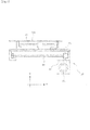
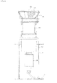
FIG. 6] FIG. 6 is a cross-section view showing the positional arrangement of the lens, light source, and camera used for recognizing components. - [
FIG. 7] FIG. 7 is a diagram to describe the processing procedure for measuring the deviation amount of the recognized position of components held on suction nozzles from embodiment 1 (part 1). - [
FIG. 8] FIG. 8 is a diagram to describe the processing procedure for measuring the deviation amount of the recognized position of components held on suction nozzles from embodiment 1 (part 2). - [
FIG. 9] FIG. 9 is a diagram to describe the processing procedure for measuring the deviation amount of the recognized position of components held on suction nozzles from embodiment 1 (part 3). - [
FIG. 10] FIG. 10 is a diagram to describe the processing procedure for measuring the deviation amount of the recognized position of components held on suction nozzles from embodiment 1 (part 4). - [
FIG. 11] FIG. 11 is a diagram to describe the processing procedure for measuring the deviation amount of the recognized position of components held on suction nozzles from embodiment 1 (part 5). - [
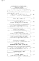
FIG. 12] FIG. 12 is a flowchart to show the processing flow of the program for measuring the recognized position deviation amount of embodiment 1 (part 1). - [
FIG. 13] FIG. 13 is a flowchart to show the processing flow of the program for measuring the recognized position deviation amount of embodiment 1 (part 2). - [
FIG. 14] FIG. 14 is a flowchart to show the processing flow of the production program ofembodiment 1. - [
FIG. 15] FIG. 15 is a diagram to show conceptually the data tables for the recognized position deviation amounts ofembodiment 2. - The following describes two modes for carrying out the invention,
embodiment 1 andembodiment 2. - The following uses
FIG. 1 to FIG. 14 to describespecific embodiment 1 of the present invention which is a modular component mounting system. - First, the following describes the configuration of the modular component mounting system using
FIG. 1 .
Multiple rotary head type (revolving head type) mounting modules 12 (component mounters) are exchangeably arranged next to each other on abase 11 of the modular component mounting system in the conveyance direction of the circuit boards. Eachmounting module 12 has: feeders 14 (such as tape feeders), circuitboard conveyance device 15,camera 16 for taking images of components,component mounting device 17, and other items onmain bed 13; and display device 19 (such as an LCD display or CRT), and operation section 20 (such as operation buttons) on the front section ofupper frame 18. In eachmounting module 12, circuit boards are conveyed sequentially using circuitboard conveyance device 15 and components are mounted on the circuit boards usingcomponent mounting device 17. - Next, the following describes the configuration of
component mounting device 17 usingFIG. 2 to FIG. 5 . - Here,
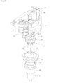
FIG. 2 is a perspective view showing the XY-axis movement device which moves mountinghead 22 in the X and Y directions;FIG. 3 is a perspective view showing the attachment configuration of mountinghead 22 with respect to thesecond X-axis slide 42 ofX-axis slide mechanism 23;FIG. 4 is a cross-section view showing the configuration ofX-axis slide mechanism 23;FIG. 5 is a perspective view showing Y-axis slide mechanism 24 and the configuration ofX-axis slide mechanism 23. - As shown in
FIG. 2 andFIG. 3 ,component mounting device 17 consists of items such as rotary type (revolving type) mountinghead 22 which has multipleexchangeable suction nozzles 21;X-axis slide mechanism 23 to move thismounting head 22 in the circuit board conveyance direction (hereafter this direction is defined as the "X-axis direction"); Y-axis slide mechanism 24 to move thisX-axis slide mechanism 23 together with mountinghead 22 in the Y-axis direction (the direction perpendicular to the circuit board conveyance direction); and nozzle raising and loweringmechanism 53 to raise and lowersuction nozzles 21 of mountinghead 22 when performing component pickup operation and mounting operation. - Y-
axis slide mechanism 24 is configured such that Y-axis slide 33 is slid in the Y-axis direction along Y-axis guides 34 by the rotational movement of Y-axis ball screw 32 which is turned by Y-axis motor 31 which is attached to theupper frame 18 side of mounting module 12 (refer toFIG. 5 ). - Then, as shown in
FIG. 4 andFIG. 5 ,X-axis slide mechanism 23 is configured such that it has a two-level slide mechanism consisting of the twoX-axis slides first X-axis slide 41 is slid in the X-axis direction alongfirst guides 43 by the rotational movement of firstX-axis ball screw 45 which is turned byfirst X-axis motor 44, wherein thefirst X-axis motor 44 andfirst guides 43 for guiding thefirst X-axis slide 41 in the X-axis direction are attached to supportingboard 33a which is secured perpendicularly to Y-axis slide 33. It is also configured such that thesecond X-axis slide 42 is slid in the X-axis direction alongsecond guides 46 by the rotational movement of secondX-axis ball screw 48 which is turned bysecond X-axis motor 47, wherein thesecond X-axis motor 47 andsecond guides 46 for guiding thesecond X-axis slide 42 in the X-axis direction are attached tofirst X-axis slide 41. - As shown in
FIG. 3 , mountinghead 22 is configured such that the circumference of the center axis of said mountinghead 22 is rotated intermittently based on the pitch angle betweensuction nozzles 21 arranged on the head (pitch movement is performed) bymotor 54 which is for rotating the head; wherein mountinghead 22 is assembled to be able to be rotated on holdingbracket 51 which is secured tosecond X-axis slide 42. On thismounting head 22,multiple nozzle holders 55 which holdpickup nozzles 21 are assembled so that they can be raised and lowered in the up/down direction (Z-direction); and, during component pickup and placement operation, a single nozzle holder 55 (suction nozzle 21) which is positioned at a specific component pickup and placement station is raised and lowered by nozzle raising andlowering mechanism 53 which has power provided by nozzle raising and lowering motor 52 (Z-axis motor). - Then, as shown in
FIG. 6 ,camera 16 for recognizing components is attached facing upwards tomain bed 13 ofmounting module 12 via supportingframe 61. The configuration is such thatlens 62 is arranged directly above thiscamera 16; dome-shaped (bowl-shaped)light source 64 is attached directly above thislens 62 via box-shaped section 63; and the center of the field of view ofcamera 16 and the center oflight source 64 are aligned. Multiple light-emitting elements 65 (such as LEDs) are arranged on the inner surface of the dome section oflight source 64 such that, when images of components being held onsuction nozzles 21 are taken bycamera 16, the components are illuminated from below bylight source 64. The upper surface oflight source 64 is covered bytransparent cover 66 through which the light passes. - Items such as
X-axis slide mechanism 23, Y-axis slide mechanism 24, firstX-axis motor 44 for moving nozzle raising and loweringmechanism 53, secondX-axis motor 47, Y-axis motor 31, nozzle raising and lowering motor 52 (Z-axis motor), andmotor 54 for rotating the head are controlled by the control device (computer) of mountingmodule 12. This control device of mountingmodule 12 functions as the image processing means which processes the image signal ofcamera 16 and recognizes the pickup position of components. - During operation of mounting module 12, each time a component supplied from a feeder 14 is picked up by a suction nozzle 21, mounting head 22 rotates only by the pitch angle amount (the movement pitch amount) of the arranged suction nozzles 21, and then repeats this so-called pickup operation for a component supplied from a feeder 14 using the next suction nozzle 21; after multiple suction nozzles 21 have each picked up a component, mounting head 22 is moved to the position for taking images during production at which a single image is to be taken for all components (the position in which the center of mounting head 22 is aligned with the center of the field of view of camera 16); then, as shown in
FIG. 11 , multiple suction nozzles 21 each holding one of the multiple components (A to D) are gathered in the field of view of camera 16 and a single image taken; then the image signal of camera 16 is processed, the pickup position of each component recognized, and the deviation of the pickup position of each component (the misalignment between the center of the component and the center of the pickup nozzle 21) is calculated; as well as this, mounting head 22 is moved directly above the mounting position of the components on the circuit board, and then each component is mounted on the circuit board considering the deviation in the pickup position of the components being held by each of the suction nozzles 21. - However, when gathering multiple components A to D within the field of vision of
camera 16 and taking a single image of all the components after illuminating the multiple components A to D being held onmultiple suction nozzles 21 from below using light source 64 (as shown inFIG. 11 ), this means that the image is taken with the position of each of the components A to D misaligned with the center of the field of view of camera 16 (the center of light source 64). If the components A to D of which an image is to be taken are BGA-type components, the pickup position of each of the components A to D is recognized by recognizing the bumps arranged in specific positions on the bottom surface of the component; however, because the position of each of the components A to D when the image is taken is misaligned with the center of the camera field of view (center of the light source), the light and dark condition (shading) of the bumps due to the illumination changes based on the distance from the center (the exposure angle with respect to the light source); as a result, the recognized position of each component A to D taken by the camera is deviated. Also, if the height position from the light source at which the image is taken changes, the exposure angle with respect to the light source changes, and the recognized position of each component A to D is deviated. - Also, there are cases in which the recognized position of each component A to D is deviated if the type of each component A to D is changed. For example, when recognizing the position of curved sections of components such as BGA-type components with bumps or the electrodes of chip capacitors, the light and dark condition (due to the light source) of the sections used for recognition changes based on the size of the curvature, and the recognized position of each component A to D is deviated. If the recognized position of each component A to D is deviated, the mounting position accuracy of each component A to D to be mounted on the circuit board deteriorates by that amount.
- As a countermeasure to this, in
embodiment 1 of the present invention, the control device of mountingmodule 12 is used to do the following: before starting production, by running the program for measuring the recognized position deviation amount fromFIG. 12 andFIG. 13 described below, and by measuring before starting production each deviation amount of the recognized position of each of the multiple components A to D being held bymultiple suction nozzles 21, then memorizing the measurement data in a memorizing means such as a hard disk or RAM, and then after that, by running the production program fromFIG. 14 described below during production; correct the deviation in the recognized position of components A to D each being held by asuction nozzle 21 by reading the measurement data of the recognized position deviation amount from said memorizing means during production. Below uses each program flowchart fromFIG. 12 to FIG. 14 to describe a control example when the quantity of suction nozzles on mountinghead 22 is four. - The recognized position deviation amount measurement programs from
FIG. 12 andFIG. 13 are run before starting production using the control device of mountingmodule 12, and this performs the role of the recognized position deviation amount measurement means which measures the deviation amount of the recognized position of each of the components A to D being held by the foursuction nozzles 21. - When this program is started, first, in
step 101, each of the components A to D is picked up by the foursuction nozzles 21. Then, continuing to step 102, as shown inFIG. 7 , mountinghead 22 is moved so that the center of thefirst suction nozzle 21 is aligned with the center of the field of view of camera 16 (the center of light source 64); and, in thenext step 103,camera 16 takes an image of component A being held by saidfirst suction nozzle 21 as it is illuminated from below bylight source 64. Then, continuing to step 104, the image signal fromcamera 16 is processed and the pickup position (Xa1, Ya1) of component A being held on thefirst suction nozzle 21 is recognized and memorized using RAM or other such means. Here, the pickup position (Xa1, Ya1) of recognized component A is the center position of component A (hereafter the same). With this, the position of the sections of component A to be recognized (for example: in the case of a BGA-type component, the bumps; in the case of a chip capacitor, the terminals) are recognized, and the center position of component A is taken as the pickup position (Xa1, Ya1) (hereafter the same). - Then, continuing to step 105, as shown in
FIG. 8 , mountinghead 22 is moved so that the center of thesecond suction nozzle 21 is aligned with the center of the field of view of camera 16 (the center of light source 64); and, in thenext step 106,camera 16 takes an image of component B being held by saidsecond suction nozzle 21 as it is illuminated from below bylight source 64. Then, continuing to step 107, the image signal fromcamera 16 is processed and the pickup position (Xb1, Yb1) of component B being held on thesecond suction nozzle 21 is recognized and memorized using RAM or other such means. - Then, continuing to step 108, as shown in
FIG. 9 , mountinghead 22 is moved so that the center of thethird suction nozzle 21 is aligned with the center of the field of view of camera 16 (the center of light source 64); and, in thenext step 109,camera 16 takes an image of component C being held by saidthird suction nozzle 21 as it is illuminated from below bylight source 64. Then, continuing to step 110, the image signal fromcamera 16 is processed and the pickup position (Xc1, Yc1) of component C being held on thethird suction nozzle 21 is recognized and memorized using RAM or other such means. - Then, continuing to step 111, as shown in
FIG. 8 , mountinghead 22 is moved so that the center of thefourth suction nozzle 21 is aligned with the center of the field of view of camera 16 (the center of light source 64); and, in thenext step 112,camera 16 takes an image of component D being held by saidfourth suction nozzle 21 as it is illuminated from below bylight source 64. Then, continuing to step 113, the image signal fromcamera 16 is processed and the pickup position (Xd1, Yd1) of component D being held on thefourth suction nozzle 21 is recognized and memorized using RAM or other such means. - As given above, after recognizing each of the pickup positions of components A to D being held by the four
suction nozzles 21, continuing to step 114 ofFIG. 13 , mountinghead 22 is moved to the position for taking pictures during production which is the position for taking pictures of all the components at the same time (the position at which the center of mountinghead 22 is aligned with the center of the field of view of camera 16); and, as shown inFIG. 11 , the four components A to D being held on the foursuction nozzles 21 are all gathered in the field of view ofcamera 16. Then, continuing to step 115,camera 16 takes a single image of all the components A to D being held by the foursuction nozzles 21 while they are illuminated from below bylight source 64; then, in thenext step 116, the image signal fromcamera 16 is processed and the pickup positions of the four components A to D (Xa2, Ya2), (Xb2, Yb2), (Xc2, Yc2), (Xd2, Yd2) being held by the foursuction nozzles 21 are recognized and memorized using RAM or other such means. - For the above, it is also acceptable to perform the processing for
steps 114 to 116 (processing to recognize the pickup position of each component A to D after taking a single image of all four components A to D) before the processing forsteps 102 to 113 (processing to recognize the pickup position of each of the components A to D after taking an individual image of each of those said components at the center of the field of view of camera 16). - Then, continuing to step 117, the distance (ΔXa1.a2, ΔYa1.a2) between the two recognized positions of component A (Xa1, Ya1), (Xa2, Ya2) being held on the
first suction nozzle 21 is calculated.

- Also, the movement distance of the first suction nozzle 21 (ΔX1, ΔY1) is calculated. If
suction nozzle 21 is moved without rotating mountinghead 22, the movement distance ofsuction nozzle 21 and the movement distance of mountinghead 22 will be the same (hereafter the same). - And, the difference between the distance separating the two recognized positions of component A being held by
first suction nozzle 21 and the movement distance of saidsuction nozzle 21 is calculated as the recognized position deviation amount of said component A and memorized using the memorizing means.

- Next, continuing to steep 118, along with calculating the distance (ΔXb1.b2, ΔYb1.b2) between the two recognized positions of component B (Xb1, Yb1), (Xb2, Yb2) being held on the
second suction nozzle 21, the movement distance of the second suction nozzle 21 (ΔX2, ΔY2) is calculated; the difference between these two distances is calculated as the recognized position deviation amount of component B and memorized using the memorizing means.

third suction nozzle 21, the movement distance of the third suction nozzle 21 (ΔX3, ΔY3) is calculated; the difference between these two distances is calculated as the recognized position deviation amount of component C and memorized using the memorizing means.
fourth suction nozzle 21, the movement distance of the fourth suction nozzle 21 (ΔX4, ΔY4) is calculated; the difference between these two distances is calculated as the recognized position deviation amount of component D and memorized using the memorizing means.

- The production program for
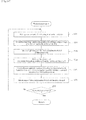
FIG. 14 is run during production by the control device of mountingmodule 12. When this program is started, first, instep 201, each of the components A to D is picked up by the foursuction nozzles 21. Next, continuing to step 202, mountinghead 22 is moved to the position for taking pictures during production which is the position for taking pictures of all the components at the same time (the position at which the center of mountinghead 22 is aligned with the center of the field of view of camera 16); and, as shown inFIG. 11 , the four components A to D being held on the foursuction nozzles 21 are all gathered in the field of view ofcamera 16. - Then, continuing to step 203,
camera 16 takes a single image of all the components A to D being held by the foursuction nozzles 21 while they are illuminated from below bylight source 64; then, in thenext step 204, the image signal fromcamera 16 is processed and the pickup positions of the four components A to D (Xa3, Ya3), (Xb3, Yb3), (Xc3, Yc3), (Xd3, Yd3) being held by the foursuction nozzles 21 are recognized. - Next, continuing to step 205, each of the recognized positions for the four components A to D (Xa3, Ya3), (Xb3, Yb3), (Xc3, Yc3), (Xd3, Yd3) are corrected based on the following equations using the measurement data of the recognized position deviation amounts read from the memorizing means.
- (1) Recognized position of component A after correction (Xa4, Ya4)


- (2) Recognized position of component B after correction (Xb4, Yb4)


- (3) Recognized position of component C after correction (Xc4, Yc4)


- (4) Recognized position of component D after correction (Xd4, Yd4)


- This
step 205 processing performs the role of the recognized position deviation correction means mentioned in the scope of the patent claims. - Next, continuing to step 206, mounting
head 22 is moved directly above the mounting position of the components on the circuit board, and then each component A to D is mounted on the circuit board considering the deviation in the pickup position of the components A to D being with respect to each of thesuction nozzles 21. - Next, continuing to step 207, a judgment is made as to whether production has been completed, and if production has not been completed, the process returns to step 201 above. In this way, processing from
steps 201 to 206 is run repeatedly during production. Next, instep 207 above, when production is judged to have been completed, the program finishes. - According to
embodiment 1 described above, by measuring the amount of deviation in the recognized position of components due to the effects of the light source, and then memorizing that measurement data using a memorizing means before production, the measurement data for the recognized position deviation amount can be read from said memorizing means during production; this makes it possible to accurately correct for the deviation in the recognized position of components due to the effects of the light source based on the recognized position deviation amount data memorized in the memorizing means, and to improve the mounting position accuracy of the components mounted on the circuit board. - However, there are cases in which an image is taken by
camera 16 of a single component being held by a single suction nozzle and the pickup position of that component recognized. In this case, it is possible to take the image with the single component being held by a single suction nozzle in the center of thecamera 16 field of view (center of the light source). Therefore, when the component and the center of thecamera 16 field of view are aligned, virtually no deviation arises in the recognized position of the component due to the effects of the light source, which means that there is no need to correct for the deviation in the recognized position of the component; however, when the component and the center of thecamera 16 field of view are not aligned, a deviation does arise in the recognized position of the component due to the effects of the light source, which means that, by using the present invention, it is possible to correct for the deviation in the recognized position of the component due to the positional relationship oflight source 64 and the component. - Furthermore, in
step 205 of the production program fromFIG. 14 mentioned above, correction of the recognized position of the four components A to D (Xa3, Ya3), (Xb3, Yb3), (Xc3, Yc3), (Xd3, Yd3) was performed using the measurement data of the recognized position deviation amounts read from the memorizing means; however, when mounting the same type of component at positions A to D usingsuction nozzles 21, it is also acceptable for a specific recognized position deviation amount for a component being held by asuction nozzle 21 to be used as a representative value, and by using this specific recognized position deviation amount for a component being held by asuction nozzle 21, the recognized position deviation amount for the other components being held bysuction nozzles 21 can be calculated. This calculation method is described below.


- If component B is arranged in a position rotated by angle θAB (=90°) with respect to component A, component B Y-direction recognized position deviation amounts CX2, CY2 are calculated using component A X-direction recognized position deviation amounts CX1, CY1 according to the equations below.


- In this way, it is acceptable to calculate the recognized position deviation amount of the other components being held on
suction nozzles 21 by using the recognized position deviation amount of a specific component being held on asuction nozzle 21. - In
embodiment 1 above, the amount of deviation in the recognized position of the components due to the effects of the light source was measured and this measurement data memorized using the memorizing means before starting production; however, inembodiment 2 of the present invention as shown inFIG. 15 , a table containing recognized position deviation amounts as parameters which represent the positional relationship between a component being held onsuction nozzles 21 and thelight source 64 is memorized for each component type in a memorizing means, and correction is performed for the deviation in the recognized position of the component being held by asuction nozzle 21 by reading the data for the recognized position deviation amount based on the positional relationship between the components being held onsuction nozzles 21 andlight source 64 for the component type from a table selected based on the component type at that time which is among the tables for each component type memorized in the said memorizing means during production. - Here, it is acceptable to calculate the table data using mounting
module 12 in the same method as inembodiment 1 above; or, it is acceptable to measure not actual components but jigs which simulate actual components; or, it is acceptable to make theoretical calculations considering the special characteristics of the deviation in the recognized position of a component. - This
embodiment 2 uses the image taking position (R) and image taking height (Z) as parameters of the positional relationship between components being held onsuction nozzles 21 andlight source 64. The distance from the center oflight source 64 to the sections of a component to be recognized (for example: in the case of a BGA-type component, the bumps; in the case of a chip capacitor, the terminals) is used for image taking position (R). The image taking height (Z) is the height from a reference position (for example, the position of camera 16) to the component. Also, the diameter or curvature of the sections of a component to be recognized (for example: in the case of a BGA-type component, the diameter of the bumps; in the case of a chip capacitor, the curvature of the terminals) are used as component type parameters. - In this
embodiment 2, during production, after taking a single image of multiple components being held onmultiple suction nozzles 21 at the same time, the deviation in the recognized position (X, Y) of the multiple components being held onmultiple suction nozzles 21 is corrected by reading the data for the recognized position deviation amount (Δx, Δy) according to the image taking position (R) and image taking height (Z) from the selected from a table based on the diameter of the bumps (or curvature of the electrodes) of the component at that time, the table being selected from the multiple tables memorized in the memorizing means. - With
embodiment 2 described above, the process for measuring the recognized position deviation amount before starting production can be omitted, therefore productivity is improved by this amount. - Furthermore, the present invention is not limited to a modular type component mounting system such as that shown in
FIG. 1 , and various modified embodiments which do not depart from the fundamental scope are possible, such as embodiments using various different type of component mounter. - 11: Base, 12: Mounting module (component mounter), 14: Feeder, 15: Circuit board conveyance device, 16: Camera, 17: Component mounting device, 21: Suction nozzle, 22: Mounting head, 23: X-axis slide mechanism; 24: Y-axis slide mechanism, 31: Y-axis motor, 33: Y-axis slide, 54: Motor for rotating head, 55: Nozzle holder, 52: Nozzle raising and lowering motor, 53: Nozzle raising and lowering mechanism, 62: Lens, 64: Light source, 65: Light emitting element, A to D: Components
Claims (6)
- What is claimed is a component mounter which is equipped with a camera to take images of components being held on suction nozzles illuminated by a light source from below and an image processing means to process the image signal of said camera in order to recognize the pickup position of the components; and which mounts said components on a circuit board considering the deviation of the pickup position of said components with respect to said suction nozzles based on the recognition results of the said image processing means;
characterized in that the component mounter is equipped with a recognized position deviation correction means for correcting the deviation in the recognized position of said components due to the positional relationship between the component and the light source which considers the deviation in the recognized position of said components of which an image is taken by said camera caused by the changing light and dark condition of the component (due to the light source) from said light source due to the positional relationship between the light source and
said components being held by the suction nozzles. - The component mounter according to claim 1 characterized in that it is equipped with multiple suction nozzles and takes a single image of all the components gathered within the field of view of said camera, with said multiple suction nozzles holding each of one of multiple components.
- The component mounter according to claim 1 or claim 2 characterized in that it is equipped with a recognized position deviation amount measuring means for measuring the deviation amount of the recognized position of the components being held on the said suction nozzles and a memorizing means for memorizing the data of the recognized position deviation amount measured by the said recognized position deviation amount measuring means,
wherein the said recognized position deviation correction means corrects the deviation in the recognized position of the components being held by said suction nozzles by reading the data of the recognized position deviation amount from the said memorizing means during production. - The component mounter according to claim 3 characterized in that it is configured such that the center of the field of view of said camera is aligned with the center of said light source,
and that said recognized position deviation amount measurement means, as well as recognizing the position of components using said image processing means by taking an image of the components while they are being held on said suction nozzles with the center of said suction nozzles being aligned with the center of the field of view of said camera before starting production, calculates said recognized position deviation amount as the difference between the movement distance of said nozzle and the distance separating the two recognized positions of the component, which are recognized using the image processing means by moving the suction nozzle to the position for taking images during production and taking an image of the component using the camera. - The component mounter according to claim 1 or claim 2 characterized in that it is equipped with a memorizing means for memorizing tables containing said recognized position deviation amounts as parameters which represent the positional relationship between a component being held on a suction nozzle and said light source,
wherein the said recognized position deviation correction means corrects the deviation in the recognized position of the components being held by said suction nozzles by reading the data of the recognized position deviation amount which is based on the positional relationship of said light source said component being held on a suction nozzle from the said table which is memorized in said memorizing means during production. - The component mounter according to claim 5 characterized in that, in said memorizing means, a said table is memorized for each component type,
and said recognized position deviation correction means corrects the deviation in the recognized position of said components being held by suction nozzles by reading the data of said recognized position deviation amounts which are based on the positional relationship of said light source and said component being held on a suction nozzle from a table selected based on the component type at that time which is among the tables for each component type memorized in the memorizing means during production.
Applications Claiming Priority (2)
| Application Number | Priority Date | Filing Date | Title |
|---|---|---|---|
| JP2011089551A JP5721509B2 (en) | 2011-04-13 | 2011-04-13 | Component mounter |
| PCT/JP2012/055716 WO2012140975A1 (en) | 2011-04-13 | 2012-03-06 | Component-mounting device |
Publications (3)
| Publication Number | Publication Date |
|---|---|
| EP2699069A1 true EP2699069A1 (en) | 2014-02-19 |
| EP2699069A4 EP2699069A4 (en) | 2015-12-16 |
| EP2699069B1 EP2699069B1 (en) | 2018-11-07 |
Family
ID=47009157
Family Applications (1)
| Application Number | Title | Priority Date | Filing Date |
|---|---|---|---|
| EP12771402.0A Active EP2699069B1 (en) | 2011-04-13 | 2012-03-06 | Component-mounting device |
Country Status (4)
| Country | Link |
|---|---|
| EP (1) | EP2699069B1 (en) |
| JP (1) | JP5721509B2 (en) |
| CN (1) | CN103493615B (en) |
| WO (1) | WO2012140975A1 (en) |
Families Citing this family (14)
| Publication number | Priority date | Publication date | Assignee | Title |
|---|---|---|---|---|
| EP2941113B1 (en) * | 2012-12-28 | 2018-11-07 | FUJI Corporation | Working machine and positional deviation data acquisition method |
| DE102013014346A1 (en) | 2013-03-18 | 2014-10-02 | Mahle International Gmbh | Method for producing a piston for an internal combustion engine and piston produced by means of this method |
| WO2015004814A1 (en) * | 2013-07-12 | 2015-01-15 | 富士機械製造株式会社 | Component mounting device |
| CN104848784A (en) * | 2014-02-19 | 2015-08-19 | 江苏腾世机电有限公司 | Position offset correction method and system of chip mounter suction nozzle units |
| CN104320921B (en) * | 2014-08-18 | 2017-12-19 | 浙江山川科技股份有限公司 | A kind of chip mounter provided with vision system |
| CN104713481A (en) * | 2015-03-21 | 2015-06-17 | 江阴新杰科技有限公司 | Visual inspection method based on planar imaging technology |
| WO2017091995A1 (en) * | 2015-12-03 | 2017-06-08 | 深圳市兴华炜科技有限公司 | Nozzle structure for self-correcting mounter and position correction method for multi-nozzle mounter |
| EP3576512B1 (en) * | 2017-01-30 | 2023-01-25 | Fuji Corporation | Component mounting machine |
| EP3644700B1 (en) * | 2017-06-20 | 2022-08-24 | Fuji Corporation | Electronic component mounting machine |
| JP6235751B1 (en) * | 2017-07-20 | 2017-11-22 | 株式会社 ベアック | Reinforcing plate application device |
| WO2019043892A1 (en) * | 2017-08-31 | 2019-03-07 | 株式会社Fuji | Component mounting machine and component mounting method |
| JP7197285B2 (en) * | 2018-05-14 | 2022-12-27 | Juki株式会社 | Mounting equipment, mounting method |
| US20230033735A1 (en) * | 2020-02-19 | 2023-02-02 | Fuji Corporation | Component mounting machine |
| CN113163702B (en) * | 2021-04-16 | 2023-04-07 | 浙江鸿广科技有限公司 | Chip mounter |
Family Cites Families (7)
| Publication number | Priority date | Publication date | Assignee | Title |
|---|---|---|---|---|
| JPH07307598A (en) * | 1994-05-11 | 1995-11-21 | Matsushita Electric Ind Co Ltd | Electronic component mounting apparatus and electronic component mounting method |
| US6276051B1 (en) * | 1998-01-29 | 2001-08-21 | Fuji Machine Mfg. Co., Ltd. | Electric-component transferring apparatus |
| JP4418014B2 (en) | 2002-11-13 | 2010-02-17 | 富士機械製造株式会社 | Calibration method for electronic component mounting apparatus |
| JP2007012889A (en) * | 2005-06-30 | 2007-01-18 | Hitachi High-Tech Instruments Co Ltd | Electronic component mounting method and electronic component mounting apparatus |
| JP2007103436A (en) * | 2005-09-30 | 2007-04-19 | Yamaha Motor Co Ltd | Component mounting method and component mounting machine |
| JP2009135267A (en) * | 2007-11-30 | 2009-06-18 | Hitachi High-Tech Instruments Co Ltd | Electronic component mounting device |
| JP5165507B2 (en) * | 2008-09-04 | 2013-03-21 | Juki株式会社 | Component mounting method |
-
2011
- 2011-04-13 JP JP2011089551A patent/JP5721509B2/en not_active Expired - Fee Related
-
2012
- 2012-03-06 WO PCT/JP2012/055716 patent/WO2012140975A1/en not_active Ceased
- 2012-03-06 CN CN201280017992.8A patent/CN103493615B/en active Active
- 2012-03-06 EP EP12771402.0A patent/EP2699069B1/en active Active
Also Published As
| Publication number | Publication date |
|---|---|
| JP5721509B2 (en) | 2015-05-20 |
| EP2699069B1 (en) | 2018-11-07 |
| WO2012140975A1 (en) | 2012-10-18 |
| EP2699069A4 (en) | 2015-12-16 |
| CN103493615A (en) | 2014-01-01 |
| CN103493615B (en) | 2016-05-18 |
| JP2012222305A (en) | 2012-11-12 |
Similar Documents
| Publication | Publication Date | Title |
|---|---|---|
| EP2699069B1 (en) | Component-mounting device | |
| JP6199798B2 (en) | Electronic component mounting device | |
| JP6174677B2 (en) | Component mounting apparatus and calibration method in component mounting apparatus | |
| EP3154327B1 (en) | Component mounting device | |
| US20190133010A1 (en) | Contactless electric power supply device | |
| WO2002005211A1 (en) | Part recognition data creation method and apparatus, electronic part mounting apparatus, and recorded medium | |
| JP6293454B2 (en) | Electronic component mounting device | |
| KR20120112068A (en) | Component mounting device, information processing device, information processing method, and substrate manufacturing method | |
| EP0471272A1 (en) | Electronic element mounting method and apparatus therefor | |
| KR101193684B1 (en) | Method and apparatus for mounting electronic parts | |
| KR20170140402A (en) | Component mounting device | |
| JPH11214900A (en) | Method a and system for correcting deviation of camera positions and dummy part for correcting camera positions | |
| JP6271514B2 (en) | Production equipment | |
| JP6674705B2 (en) | Image recognition device | |
| EP3370493B1 (en) | Base plate position searching device and component mounting machine | |
| CN114375617A (en) | Method for manufacturing mounting substrate and component mounting device | |
| JP5787397B2 (en) | Electronic component mounting apparatus and electronic component mounting method | |
| JP6849547B2 (en) | Eccentricity correction method for parts holder | |
| JP6056059B2 (en) | Component mounting apparatus, position correction method, board manufacturing method, and information processing apparatus | |
| JP2006073959A (en) | Component recognition device, surface mounter and component testing device | |
| JP4408069B2 (en) | Component recognition apparatus and surface mounter equipped with the same | |
| JP2003234599A (en) | Surface mounting machine | |
| JP2006073960A (en) | Component recognition device, surface mounter and component testing device | |
| JP4598513B2 (en) | Electronic component mounting device | |
| JP2008171866A (en) | Focus adjustment method and scaling acquisition method of mounting machine camera |
Legal Events
| Date | Code | Title | Description |
|---|---|---|---|
| PUAI | Public reference made under article 153(3) epc to a published international application that has entered the european phase |
Free format text: ORIGINAL CODE: 0009012 |
|
| 17P | Request for examination filed |
Effective date: 20131011 |
|
| AK | Designated contracting states |
Kind code of ref document: A1 Designated state(s): AL AT BE BG CH CY CZ DE DK EE ES FI FR GB GR HR HU IE IS IT LI LT LU LV MC MK MT NL NO PL PT RO RS SE SI SK SM TR |
|
| DAX | Request for extension of the european patent (deleted) | ||
| RA4 | Supplementary search report drawn up and despatched (corrected) |
Effective date: 20151113 |
|
| RIC1 | Information provided on ipc code assigned before grant |
Ipc: H05K 13/04 20060101AFI20151109BHEP Ipc: H05K 13/08 20060101ALI20151109BHEP |
|
| GRAP | Despatch of communication of intention to grant a patent |
Free format text: ORIGINAL CODE: EPIDOSNIGR1 |
|
| STAA | Information on the status of an ep patent application or granted ep patent |
Free format text: STATUS: GRANT OF PATENT IS INTENDED |
|
| INTG | Intention to grant announced |
Effective date: 20180629 |
|
| GRAS | Grant fee paid |
Free format text: ORIGINAL CODE: EPIDOSNIGR3 |
|
| GRAA | (expected) grant |
Free format text: ORIGINAL CODE: 0009210 |
|
| STAA | Information on the status of an ep patent application or granted ep patent |
Free format text: STATUS: THE PATENT HAS BEEN GRANTED |
|
| RAP1 | Party data changed (applicant data changed or rights of an application transferred) |
Owner name: FUJI CORPORATION |
|
| AK | Designated contracting states |
Kind code of ref document: B1 Designated state(s): AL AT BE BG CH CY CZ DE DK EE ES FI FR GB GR HR HU IE IS IT LI LT LU LV MC MK MT NL NO PL PT RO RS SE SI SK SM TR |
|
| REG | Reference to a national code |
Ref country code: GB Ref legal event code: FG4D |
|
| REG | Reference to a national code |
Ref country code: CH Ref legal event code: EP Ref country code: AT Ref legal event code: REF Ref document number: 1063686 Country of ref document: AT Kind code of ref document: T Effective date: 20181115 |
|
| REG | Reference to a national code |
Ref country code: IE Ref legal event code: FG4D |
|
| REG | Reference to a national code |
Ref country code: DE Ref legal event code: R096 Ref document number: 602012053212 Country of ref document: DE |
|
| REG | Reference to a national code |
Ref country code: CH Ref legal event code: PK Free format text: BERICHTIGUNGEN |
|
| RIN2 | Information on inventor provided after grant (corrected) |
Inventor name: KAWAI, HIDETOSHI Inventor name: AKATSUKA, RYOTA |
|
| REG | Reference to a national code |
Ref country code: NL Ref legal event code: FP |
|
| REG | Reference to a national code |
Ref country code: LT Ref legal event code: MG4D |
|
| REG | Reference to a national code |
Ref country code: AT Ref legal event code: MK05 Ref document number: 1063686 Country of ref document: AT Kind code of ref document: T Effective date: 20181107 |
|
| PG25 | Lapsed in a contracting state [announced via postgrant information from national office to epo] |
Ref country code: ES Free format text: LAPSE BECAUSE OF FAILURE TO SUBMIT A TRANSLATION OF THE DESCRIPTION OR TO PAY THE FEE WITHIN THE PRESCRIBED TIME-LIMIT Effective date: 20181107 Ref country code: NO Free format text: LAPSE BECAUSE OF FAILURE TO SUBMIT A TRANSLATION OF THE DESCRIPTION OR TO PAY THE FEE WITHIN THE PRESCRIBED TIME-LIMIT Effective date: 20190207 Ref country code: IS Free format text: LAPSE BECAUSE OF FAILURE TO SUBMIT A TRANSLATION OF THE DESCRIPTION OR TO PAY THE FEE WITHIN THE PRESCRIBED TIME-LIMIT Effective date: 20190307 Ref country code: HR Free format text: LAPSE BECAUSE OF FAILURE TO SUBMIT A TRANSLATION OF THE DESCRIPTION OR TO PAY THE FEE WITHIN THE PRESCRIBED TIME-LIMIT Effective date: 20181107 Ref country code: LT Free format text: LAPSE BECAUSE OF FAILURE TO SUBMIT A TRANSLATION OF THE DESCRIPTION OR TO PAY THE FEE WITHIN THE PRESCRIBED TIME-LIMIT Effective date: 20181107 Ref country code: BG Free format text: LAPSE BECAUSE OF FAILURE TO SUBMIT A TRANSLATION OF THE DESCRIPTION OR TO PAY THE FEE WITHIN THE PRESCRIBED TIME-LIMIT Effective date: 20190207 Ref country code: AT Free format text: LAPSE BECAUSE OF FAILURE TO SUBMIT A TRANSLATION OF THE DESCRIPTION OR TO PAY THE FEE WITHIN THE PRESCRIBED TIME-LIMIT Effective date: 20181107 Ref country code: FI Free format text: LAPSE BECAUSE OF FAILURE TO SUBMIT A TRANSLATION OF THE DESCRIPTION OR TO PAY THE FEE WITHIN THE PRESCRIBED TIME-LIMIT Effective date: 20181107 Ref country code: LV Free format text: LAPSE BECAUSE OF FAILURE TO SUBMIT A TRANSLATION OF THE DESCRIPTION OR TO PAY THE FEE WITHIN THE PRESCRIBED TIME-LIMIT Effective date: 20181107 |
|
| PG25 | Lapsed in a contracting state [announced via postgrant information from national office to epo] |
Ref country code: RS Free format text: LAPSE BECAUSE OF FAILURE TO SUBMIT A TRANSLATION OF THE DESCRIPTION OR TO PAY THE FEE WITHIN THE PRESCRIBED TIME-LIMIT Effective date: 20181107 Ref country code: SE Free format text: LAPSE BECAUSE OF FAILURE TO SUBMIT A TRANSLATION OF THE DESCRIPTION OR TO PAY THE FEE WITHIN THE PRESCRIBED TIME-LIMIT Effective date: 20181107 Ref country code: AL Free format text: LAPSE BECAUSE OF FAILURE TO SUBMIT A TRANSLATION OF THE DESCRIPTION OR TO PAY THE FEE WITHIN THE PRESCRIBED TIME-LIMIT Effective date: 20181107 Ref country code: GR Free format text: LAPSE BECAUSE OF FAILURE TO SUBMIT A TRANSLATION OF THE DESCRIPTION OR TO PAY THE FEE WITHIN THE PRESCRIBED TIME-LIMIT Effective date: 20190208 Ref country code: PT Free format text: LAPSE BECAUSE OF FAILURE TO SUBMIT A TRANSLATION OF THE DESCRIPTION OR TO PAY THE FEE WITHIN THE PRESCRIBED TIME-LIMIT Effective date: 20190307 |
|
| PG25 | Lapsed in a contracting state [announced via postgrant information from national office to epo] |
Ref country code: PL Free format text: LAPSE BECAUSE OF FAILURE TO SUBMIT A TRANSLATION OF THE DESCRIPTION OR TO PAY THE FEE WITHIN THE PRESCRIBED TIME-LIMIT Effective date: 20181107 Ref country code: DK Free format text: LAPSE BECAUSE OF FAILURE TO SUBMIT A TRANSLATION OF THE DESCRIPTION OR TO PAY THE FEE WITHIN THE PRESCRIBED TIME-LIMIT Effective date: 20181107 Ref country code: CZ Free format text: LAPSE BECAUSE OF FAILURE TO SUBMIT A TRANSLATION OF THE DESCRIPTION OR TO PAY THE FEE WITHIN THE PRESCRIBED TIME-LIMIT Effective date: 20181107 |
|
| REG | Reference to a national code |
Ref country code: DE Ref legal event code: R097 Ref document number: 602012053212 Country of ref document: DE |
|
| PG25 | Lapsed in a contracting state [announced via postgrant information from national office to epo] |
Ref country code: SM Free format text: LAPSE BECAUSE OF FAILURE TO SUBMIT A TRANSLATION OF THE DESCRIPTION OR TO PAY THE FEE WITHIN THE PRESCRIBED TIME-LIMIT Effective date: 20181107 Ref country code: EE Free format text: LAPSE BECAUSE OF FAILURE TO SUBMIT A TRANSLATION OF THE DESCRIPTION OR TO PAY THE FEE WITHIN THE PRESCRIBED TIME-LIMIT Effective date: 20181107 Ref country code: RO Free format text: LAPSE BECAUSE OF FAILURE TO SUBMIT A TRANSLATION OF THE DESCRIPTION OR TO PAY THE FEE WITHIN THE PRESCRIBED TIME-LIMIT Effective date: 20181107 Ref country code: SK Free format text: LAPSE BECAUSE OF FAILURE TO SUBMIT A TRANSLATION OF THE DESCRIPTION OR TO PAY THE FEE WITHIN THE PRESCRIBED TIME-LIMIT Effective date: 20181107 |
|
| PLBE | No opposition filed within time limit |
Free format text: ORIGINAL CODE: 0009261 |
|
| STAA | Information on the status of an ep patent application or granted ep patent |
Free format text: STATUS: NO OPPOSITION FILED WITHIN TIME LIMIT |
|
| 26N | No opposition filed |
Effective date: 20190808 |
|
| PG25 | Lapsed in a contracting state [announced via postgrant information from national office to epo] |
Ref country code: MC Free format text: LAPSE BECAUSE OF FAILURE TO SUBMIT A TRANSLATION OF THE DESCRIPTION OR TO PAY THE FEE WITHIN THE PRESCRIBED TIME-LIMIT Effective date: 20181107 Ref country code: SI Free format text: LAPSE BECAUSE OF FAILURE TO SUBMIT A TRANSLATION OF THE DESCRIPTION OR TO PAY THE FEE WITHIN THE PRESCRIBED TIME-LIMIT Effective date: 20181107 |
|
| REG | Reference to a national code |
Ref country code: CH Ref legal event code: PL |
|
| GBPC | Gb: european patent ceased through non-payment of renewal fee |
Effective date: 20190306 |
|
| PG25 | Lapsed in a contracting state [announced via postgrant information from national office to epo] |
Ref country code: LU Free format text: LAPSE BECAUSE OF NON-PAYMENT OF DUE FEES Effective date: 20190306 |
|
| REG | Reference to a national code |
Ref country code: BE Ref legal event code: MM Effective date: 20190331 |
|
| PG25 | Lapsed in a contracting state [announced via postgrant information from national office to epo] |
Ref country code: CH Free format text: LAPSE BECAUSE OF NON-PAYMENT OF DUE FEES Effective date: 20190331 Ref country code: LI Free format text: LAPSE BECAUSE OF NON-PAYMENT OF DUE FEES Effective date: 20190331 Ref country code: IE Free format text: LAPSE BECAUSE OF NON-PAYMENT OF DUE FEES Effective date: 20190306 Ref country code: GB Free format text: LAPSE BECAUSE OF NON-PAYMENT OF DUE FEES Effective date: 20190306 |
|
| PG25 | Lapsed in a contracting state [announced via postgrant information from national office to epo] |
Ref country code: BE Free format text: LAPSE BECAUSE OF NON-PAYMENT OF DUE FEES Effective date: 20190331 |
|
| PG25 | Lapsed in a contracting state [announced via postgrant information from national office to epo] |
Ref country code: TR Free format text: LAPSE BECAUSE OF FAILURE TO SUBMIT A TRANSLATION OF THE DESCRIPTION OR TO PAY THE FEE WITHIN THE PRESCRIBED TIME-LIMIT Effective date: 20181107 |
|
| PG25 | Lapsed in a contracting state [announced via postgrant information from national office to epo] |
Ref country code: MT Free format text: LAPSE BECAUSE OF NON-PAYMENT OF DUE FEES Effective date: 20190306 |
|
| PG25 | Lapsed in a contracting state [announced via postgrant information from national office to epo] |
Ref country code: CY Free format text: LAPSE BECAUSE OF FAILURE TO SUBMIT A TRANSLATION OF THE DESCRIPTION OR TO PAY THE FEE WITHIN THE PRESCRIBED TIME-LIMIT Effective date: 20181107 |
|
| PG25 | Lapsed in a contracting state [announced via postgrant information from national office to epo] |
Ref country code: HU Free format text: LAPSE BECAUSE OF FAILURE TO SUBMIT A TRANSLATION OF THE DESCRIPTION OR TO PAY THE FEE WITHIN THE PRESCRIBED TIME-LIMIT; INVALID AB INITIO Effective date: 20120306 |
|
| PG25 | Lapsed in a contracting state [announced via postgrant information from national office to epo] |
Ref country code: MK Free format text: LAPSE BECAUSE OF FAILURE TO SUBMIT A TRANSLATION OF THE DESCRIPTION OR TO PAY THE FEE WITHIN THE PRESCRIBED TIME-LIMIT Effective date: 20181107 |
|
| P01 | Opt-out of the competence of the unified patent court (upc) registered |
Effective date: 20230328 |
|
| PGFP | Annual fee paid to national office [announced via postgrant information from national office to epo] |
Ref country code: NL Payment date: 20250217 Year of fee payment: 14 |
|
| PGFP | Annual fee paid to national office [announced via postgrant information from national office to epo] |
Ref country code: DE Payment date: 20250128 Year of fee payment: 14 |
|
| PGFP | Annual fee paid to national office [announced via postgrant information from national office to epo] |
Ref country code: FR Payment date: 20250210 Year of fee payment: 14 |
|
| PGFP | Annual fee paid to national office [announced via postgrant information from national office to epo] |
Ref country code: IT Payment date: 20250211 Year of fee payment: 14 |