EP2699061A2 - Lighting control system - Google Patents
Lighting control system Download PDFInfo
- Publication number
- EP2699061A2 EP2699061A2 EP13168657.8A EP13168657A EP2699061A2 EP 2699061 A2 EP2699061 A2 EP 2699061A2 EP 13168657 A EP13168657 A EP 13168657A EP 2699061 A2 EP2699061 A2 EP 2699061A2
- Authority
- EP
- European Patent Office
- Prior art keywords
- lighting control
- brightness
- illuminance
- lighting
- control device
- Prior art date
- Legal status (The legal status is an assumption and is not a legal conclusion. Google has not performed a legal analysis and makes no representation as to the accuracy of the status listed.)
- Withdrawn
Links
Images





Classifications
-
- H—ELECTRICITY
- H05—ELECTRIC TECHNIQUES NOT OTHERWISE PROVIDED FOR
- H05B—ELECTRIC HEATING; ELECTRIC LIGHT SOURCES NOT OTHERWISE PROVIDED FOR; CIRCUIT ARRANGEMENTS FOR ELECTRIC LIGHT SOURCES, IN GENERAL
- H05B47/00—Circuit arrangements for operating light sources in general, i.e. where the type of light source is not relevant
- H05B47/10—Controlling the light source
- H05B47/105—Controlling the light source in response to determined parameters
- H05B47/11—Controlling the light source in response to determined parameters by determining the brightness or colour temperature of ambient light
-
- H—ELECTRICITY
- H05—ELECTRIC TECHNIQUES NOT OTHERWISE PROVIDED FOR
- H05B—ELECTRIC HEATING; ELECTRIC LIGHT SOURCES NOT OTHERWISE PROVIDED FOR; CIRCUIT ARRANGEMENTS FOR ELECTRIC LIGHT SOURCES, IN GENERAL
- H05B45/00—Circuit arrangements for operating light-emitting diodes [LED]
- H05B45/10—Controlling the intensity of the light
- H05B45/12—Controlling the intensity of the light using optical feedback
-
- Y—GENERAL TAGGING OF NEW TECHNOLOGICAL DEVELOPMENTS; GENERAL TAGGING OF CROSS-SECTIONAL TECHNOLOGIES SPANNING OVER SEVERAL SECTIONS OF THE IPC; TECHNICAL SUBJECTS COVERED BY FORMER USPC CROSS-REFERENCE ART COLLECTIONS [XRACs] AND DIGESTS
- Y02—TECHNOLOGIES OR APPLICATIONS FOR MITIGATION OR ADAPTATION AGAINST CLIMATE CHANGE
- Y02B—CLIMATE CHANGE MITIGATION TECHNOLOGIES RELATED TO BUILDINGS, e.g. HOUSING, HOUSE APPLIANCES OR RELATED END-USER APPLICATIONS
- Y02B20/00—Energy efficient lighting technologies, e.g. halogen lamps or gas discharge lamps
- Y02B20/40—Control techniques providing energy savings, e.g. smart controller or presence detection
Definitions
- Embodiments relate to a lighting control system.
- conventional lighting control systems to control lighting devices are designed to sense an illuminance around a lighting device using an illuminance sensor (not shown), and thereafter to control the lighting device according to the sensed illuminance.
- the illuminance sensor may fail to accurately sense an illuminance around the lighting device if a light receiving area thereof is reduced or covered by foreign materials, such as fallen leaves, bird guano, dust, etc. This may cause a lighting device, such as a street light, to malfunction, by, for example, turning on before sunset and failing to turn off after sunrise, thereby shortening lifespan and unnecessarily consuming power.
- removal of foreign materials from the illuminance sensor may require frequent cleaning of the illuminance sensor, which may increase maintenance/repair costs of the lighting device.
- Embodiments provide a lighting control system, which may more accurately control lighting devices without being influenced by foreign materials.
- a lighting control system includes an object lighting control device that generates an object brightness control signal to control an object brightness of an object lighting device provided in an object district using a sensed result of an object illuminance around the object lighting device and using reference data, and at least one reference lighting control device that generates a reference brightness control signal to control a reference brightness of a reference lighting device provided in a reference district using a sensed result of a reference illuminance around the reference lighting device, and that transmits at least one of the reference illuminance and the reference brightness as the reference data to the object lighting control device in response to a request of the object lighting control device.
- the object lighting control device may calibrate at least one of the object illuminance and the object brightness using at least one of an illuminance comparison result between the object illuminance and the reference illuminance and a brightness comparison result between the reference brightness and the object brightness, and the object lighting control device may generate the object brightness control signal using at least one of the calibrated object illuminance and object brightness.
- the object lighting control device may calibrate the object illuminance using the reference illuminance when the illuminance comparison result shows that a difference between the object illuminance and the reference illuminance diverges from a first allowable deviation range.
- the object lighting control device may calibrate the object brightness using the reference brightness if the brightness comparison result shows that a difference between the object brightness and the reference brightness diverges from a second allowable deviation range.
- the at least one reference lighting control device may include a plurality of reference lighting control devices, and the object lighting control device may calibrate the object illuminance using an average value of a plurality of reference illuminances sensed by the plurality of reference lighting control devices.
- the at least one reference lighting control device may include a plurality of reference lighting control devices, and the object lighting control device may calibrate the object brightness using an average value of a plurality of reference brightnesses output from the plurality of reference lighting control devices.
- the at least one reference lighting control device may include a plurality of reference lighting control devices, and the object lighting control device may calibrate the object illuminance using an average value of highest-frequency reference illuminances among a plurality of reference illuminances sensed by the plurality of reference lighting control devices.
- the at least one reference lighting control device may include a plurality of reference lighting control devices, and the object lighting control device may calibrate the object brightness using an average value of highest-frequency reference brightnesses among a plurality of reference brightnesses output from the plurality of reference lighting control devices.
- the object lighting control device may transmit a lighting control request signal in response to at least one of the illuminance comparison result and the brightness comparison result, and the reference lighting control device may transmit the reference brightness control signal as the object brightness control signal to the object lighting device in response to the lighting control request signal.
- the object lighting control device may transmit an inherent identification signal of the reference lighting control device to the object lighting device when transmitting the lighting control request signal to the reference lighting control device, and wherein the object lighting device may allow control of the reference lighting control device that is recognized based on the identification signal.
- the object lighting control device may include an object illuminance sensing unit configured to sense the object illuminance, an object control unit configured to generate the object brightness control signal using the sensed object illuminance and the reference data, and an object communication unit configured to transmit the object brightness control signal to the object lighting device.
- the object lighting control device may further include an object signal conversion unit that amplifies the object illuminance sensed by the object illuminance sensing unit and convert a form of the object illuminance into a form of voltage or frequency and that outputs the converted object illuminance, and the object control unit may generate the object brightness control signal using the converted object illuminance and the reference data.
- an object signal conversion unit that amplifies the object illuminance sensed by the object illuminance sensing unit and convert a form of the object illuminance into a form of voltage or frequency and that outputs the converted object illuminance
- the object control unit may generate the object brightness control signal using the converted object illuminance and the reference data.
- the object control unit may generate the object brightness control signal in the form of a pulse width modulation signal.
- the reference lighting control device may include a reference illuminance sensing unit configured to sense the reference illuminance, a reference control unit configured to generate the reference brightness control signal using the sensed reference illuminance, and a reference communication unit configured to transmit the reference brightness control signal to the reference lighting device.
- the reference lighting control device may further include a reference signal conversion unit that amplifies the reference illuminance sensed by the reference illuminance sensing unit and converts a form of the reference illuminance into a form of voltage or frequency and that outputs the converted reference illuminance, and the reference control unit may generate the reference brightness control signal using the converted reference illuminance.
- the object lighting control device may further include a storage unit configured to store the implementation number of calibration of at least one of the object illuminance and the object brightness.
- the lighting control system may manage the object lighting device using the implementation number of calibration stored in the storage unit.
- a lighting control system in another embodiment, includes an object lighting control device that generates a lighting control request signal using a sensed result of an object illuminance around an object lighting device provided in an object district and using reference data, and a reference lighting control device that generates a reference brightness control signal to control a reference brightness of a reference lighting device provided in a reference district using a sensed result of a reference illuminance around the reference lighting device, and that outputs the reference brightness control signal as an object brightness control signal to control a brightness of the object lighting device to the object lighting control device in response to the lighting control request signal received from the object lighting control device.
- FIG. 1 is a layout diagram of a lighting control system and a lighting device according to an embodiment.
- the lighting control system is comprised of first to N th lighting control devices 100 1 to 100 N.
- N is a positive integer of 1 or more.
- the first to N th lighting control devices 100 1 to 100 N are respectively allotted to first to N th districts 200 1 to 200 N .
- Each of the first to N th districts 200 1 to 200 N is provided with at least one lighting device 200.
- the at least one lighting device 200 provided in each district is controlled by first to N th brightness control signals L 1 to L N which are generated respectively by the corresponding lighting control devices 100 1 to 100 N .
- the first lighting control device 100 1 is allotted to the first district 200 1 , and at least one lighting device 200 provided in the first district 200 1 is controlled by the first brightness control signal L 1 .
- the n th lighting control device 100 n is allotted to the n th district 200 n , and at least one lighting device 200 provided in the n th district 200 N is controlled by the n th brightness control signal L N .
- a lighting control device that is an object of interest among the first to N th lighting control devices 100 1 to 100 N is referred to as 'object lighting control device 100 x ' (here, 1 ⁇ X ⁇ N)
- 'reference lighting control device 100 Y ' (here, X ⁇ Y, 1 ⁇ Y ⁇ N).
- the object lighting control device 100 X may control the lighting device 200 as follows by referring to the reference lighting control device 100 Y .
- the object lighting control device 100 X refers to the reference lighting control device 100 Y and the reference lighting control device 100 Y is referred to by the object lighting control device 100 X will be described.
- the object lighting control device 100 X and the reference lighting control device 100 Y may have the same configuration and may perform the same operation.
- FIG. 2 is a schematic block diagram of a lighting control system according to an embodiment, which includes the object lighting control device 100 X and the reference lighting control device 100 Y .
- the object lighting control device 100x as exemplarily shown in FIG. 2 may include an object illuminance sensing unit 110 X , an object signal conversion unit 120 X , an object control unit 130x, an object communication unit 140x, and an object antenna 150 X , and may further include an object storage unit 132 X .
- the object illuminance sensing unit 110 X serves to sense an illuminance (hereinafter referred to as 'object illuminance') around at least one lighting device 200 (hereinafter referred to as 'object lighting device') that is provided in the X th district 200x (hereinafter referred to as 'object district') among the first to N th districts 200 1 to 200 N .
- 'object lighting device' an illuminance sensed by the object illuminance sensing unit 110 X included in the object lighting control device 100 X substantially equals an illuminance around the object lighting device 200 provided in the object district 200 X .
- the object illuminance sensing unit 110 X may function to change light into electricity and to output an object illuminance signal corresponding to the electricity.
- the object signal conversion unit 120 X may convert the form of the object illuminance transmitted from the object illuminance sensing unit 110 X into voltage or frequency by amplifying the object illuminance, and output the object illuminance having the converted form to the object control unit 130x.
- the original form of the object illuminance may be voltage.
- the object control unit 130 X generates a brightness control signal (hereinafter referred to as 'object brightness control signal') using reference data and an object illuminance output from the object signal conversion unit 120 X .
- the reference data includes at least one of a reference illuminance and a reference brightness.
- the reference illuminance means an illuminance around the lighting device (hereinafter referred to as 'reference lighting device') provided in at least one district 200 Y (hereinafter referred to as 'reference district'), different from the object district 200x, among the first to N th districts 200 1 to 200 N .
- the reference brightness means a brightness (or luminance) of the reference lighting device 200.
- the object control unit 130 X calibrates at least one of an object illuminance and an object brightness using at least one of an illuminance comparison result and a brightness comparison result.
- the object brightness means a brightness of the object lighting device 200.
- the illuminance comparison result means a result of comparing an object illuminance with a reference illuminance
- the brightness comparison result means a result of comparing an object brightness with a reference brightness. This comparison may be performed by the object control unit 130 X .
- the object control unit 130x may further function to detect the level of an object illuminance output from the object signal conversion unit 120x, and to generate a Pulse Width Modulation (PWM) object brightness control signal having a pulse width (or duty) corresponding to the detected level.
- PWM Pulse Width Modulation
- the aforementioned object brightness control signal may take the form of digital data corresponding to a pulse duty ratio. Conversion from a PWM signal into digital data may be performed by the object control unit 130 X via a prestored algorithm.
- a brightness degree of the LEDs may vary according to a duty ratio of the PWM object brightness control signal.
- the object lighting control device 100 X is connected in a wireless manner to the object lighting device 200 provided in the object district 200 X and/or the reference lighting control device 100 Y through the object communication unit 140 X and the object antenna 150 X , the embodiment is not limited thereto. That is, the object lighting control device 100 X may be connected in a wired manner to the object lighting device 200 provided in the object district 200x and/or the reference lighting control device 100 Y . If the object lighting control device 100 X is connected in a wired manner to the object lighting device 200, the object antenna 150 X is omitted.
- the object communication unit 140 X may transmit an object brightness control signal, generated by the object control unit 130 X , to the object lighting device 200 through the object antenna 150 X using short-range wireless communication, such as RF wireless communication or ZigBee wireless communication.
- short-range wireless communication such as RF wireless communication or ZigBee wireless communication.
- the reference lighting control device 100 Y may include a reference illuminance sensing unit 110 Y , a reference signal conversion unit 120 Y , a reference control unit 130 Y , a reference communication unit 140 Y , and a reference antenna 150 Y , and may further include a reference storage unit 132 Y .
- the reference illuminance sensing unit 110 Y the reference signal conversion unit 120 Y , the reference control unit 130 Y , the reference communication unit 140 Y , the reference antenna 150 Y , and the reference storage unit 132 Y differ in name from the object illuminance sensing unit 110 X , the object signal conversion unit 120 X , the object control unit 130 X , the object communication unit 140 X , the object antenna 150x, and the object storage unit 132x, they may perform the same functions.
- the reference illuminance sensing unit 110 Y serves to sense a reference illuminance around at least one reference lighting device 200 that is provided in the reference district 200 Y among the first to N th districts 200 1 to 200 N .
- the reference signal conversion unit 120 Y may convert the form of the reference illuminance into voltage or frequency via amplification of the reference illuminance sensed by the reference illuminance sensing unit 110 Y and output the converted reference illuminance to the reference control unit 130 Y .
- the reference control unit 130 Y generates a brightness control signal (hereinafter referred to as 'reference brightness control signal') using a sensed reference illuminance result.
- the aforementioned reference brightness may be proportional to the level of a reference brightness control signal. That is, the reference lighting device 200 may emit light having brightness corresponding to the level of a reference brightness control signal.
- the reference control unit 130 Y may transmit at least one of a reference illuminance and a reference brightness as the reference data to the object lighting control device 100 X in response to a request of the object lighting control device 100 X .
- the reference communication unit 140 Y and the reference antenna 150 Y serve to transmit a reference brightness control signal, generated by the reference control unit 130 Y , to the reference lighting device 200.
- the object lighting control device 100 X may refer to a plurality of reference lighting control devices 100 Y .
- FIG. 3 is a flowchart explaining a lighting control method that is performed by the lighting control system according to an embodiment.
- an object illuminance is detected (Operation 210).
- the object illuminance sensing unit 110 X senses an object illuminance around the object lighting device 200, and the object signal conversion unit 120 X amplifies the sensed object illuminance into the form of voltage or frequency and outputs the amplifying result as the detected object illuminance to the object control unit 130x.
- the object control unit 130 X After Operation 210, the object control unit 130 X generates and transmits an interrupt signal to at least one reference lighting control device 100 Y through the object communication unit 140 X and the object antenna 150 X (Operation 220).
- the object control unit 130 X requests the at least one reference lighting control device 100 Y that permits the object lighting control device 100 X to access upon receiving the interrupt signal for reference data, i.e. at least one of a reference illuminance and a reference brightness (Operation 230). To this end, the object control unit 130 X may transmit a signal that requests for at least one of a reference illuminance and a reference brightness to the reference lighting control device 100 Y through the object communication unit 140 X and the object antenna 150 X .
- the object control unit 130 X of the object lighting control device 100 X may receive reference data, i.e. at least one of a reference illuminance and a reference brightness, from the reference lighting control device 100 Y through the object communication unit 140 X and the object antenna 150 X (Operation 240).
- reference data i.e. at least one of a reference illuminance and a reference brightness
- the object control unit 130x may process the received reference data (operation 250).
- the object control unit 130x may process the received reference data in various ways as follows.
- the object control unit 130x may receive a plurality of reference illuminances from a plurality of reference lighting control devices 100 Y , and may calculate an average value of the plurality of received reference illuminances.
- the average value may be used to calibrate an object illuminance in Operation 270.
- the object control unit 130 X may calculate an average value of highest-frequency reference illuminances among a plurality of reference illuminances sensed by the plurality of reference lighting control devices 100 Y .
- the average value may be used to calibrate an object illuminance in Operation 270, and a plurality of highest-frequency reference illuminances may be present.
- a place where the reference lighting device 200 is located is temporarily affected by, e.g., a cloud or a shadow of the surrounding building, a plurality of reference illuminances may significantly differ from one another with deviations therebetween.
- an object illuminance may be calibrated using the average value of the highest-frequency reference illuminances among the plurality of reference illuminances.
- the object control unit 130 X may receive a plurality of reference brightnesses output from a plurality of reference lighting control devices 100 Y , and may calculate an average value of the plurality of received reference brightnesses.
- the average value may be used to calibrate an object brightness in Operation 270.
- the object control unit 130 X may calculate an average value of highest-frequency reference brightnesses among a plurality of reference brightnesses output from the plurality of reference lighting control devices 100 Y .
- the average value may be used to calibrate an object brightness in Operation 270, and a plurality of highest-frequency reference brightnesses may be present.
- Operation 250 may be omitted.
- the object control unit 130 X judges whether or not to calibrate at least one of an object illuminance and an object brightness (Operation 260).
- a light receiving area of the object illuminance sensing unit 110 X may be reduced or blocked.
- the object lighting control device 100 X may allow the reference lighting control device 100 Y to directly control the object lighting device 200, instead of calibrating at least one of an object illuminance and an object brightness (Operation 290).
- the object control unit 130 X generates and outputs a lighting control request signal to the reference lighting control device 100 Y , and the reference lighting control device 100 Y transmits a reference brightness control signal serving as an object brightness control signal to the object lighting device 200 in response to the lighting control request signal. That is, the reference lighting control device 100 Y instead of the object lighting control device 100 X controls the object lighting device 200.
- the object control unit 130 X may transmit an inherent identification signal of the reference lighting control device 100 Y to the object lighting device 200. This serves to allow the object lighting device 200 to be controlled by the reference lighting control device 100 Y corresponding to the received identification signal.
- the object control unit 130 X may calibrate at least one of an object illuminance and an object brightness (Operation 270).
- the object control unit 130 X may use at least one of an illuminance comparison result and a brightness comparison result. For example, if it is recognized from an illuminance comparison result that a difference between an object illuminance and a reference illuminance is continuously maintained for a predetermined duration or more, the object control unit 130 X may perform Operation 290 based on judgment that the light receiving area is blocked. In addition, if it is recognized from a brightness comparison result that a difference between an object brightness and a reference brightness is continuously maintained for a predetermined duration or more, the object control unit 130 X may perform Operation 290 based on judgment that the light receiving area is blocked.
- duration from sunset till sunrise in the summer season differs from duration from sunset till sunrise in the winter season, such difference is not over a predetermined duration. Accordingly, if a difference between an object illuminance and a reference illuminance or a difference between an object brightness and a reference brightness is continuously maintained for the predetermined duration or more, it may be judged that the light receiving area is blocked by foreign materials.
- the object control unit 130 X may proceed to Operation 270 without generating a lighting control request signal based on judgment that the light receiving area is not blocked, but is reduced.
- the object control unit 130x may proceed to Operation 270 without generating a lighting control request signal based on judgment that the light receiving area is not blocked, but is reduced. If a difference between an object illuminance and a reference illuminance or a difference between an object brightness and a reference brightness is not continuously maintained for the predetermined duration or more, this means that the light receiving area is not blocked by foreign materials.
- the object control unit 130x may calibrate at least one of an object illuminance and an object brightness using reference data (operation 270). That is, the object control unit 130 X may calibrate an object illuminance using a reference illuminance, and may calibrate an object brightness using a reference brightness.
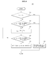
- FIG. 4 is a flowchart explaining one embodiment, designated by reference numeral 300, of Operation 270 in FIG. 3 .
- the object control unit 130 X calibrates an object illuminance S 1 using a reference illuminance S A when an illuminance comparison result shows that a difference between the object illuminance S 1 and the reference illuminance S A diverges from a first allowable deviation range (Operations 310 to 360).
- the reference illuminance S A will be described as serving to calibrate the object illuminance S 1 , the following description will be directly applied even in the case in which, instead of the reference illuminance S A , an average value of a plurality of reference illuminances is used, or an average value of highest-frequency reference illuminances among a plurality of reference illuminances is used.
- the object control unit 130x judges whether or not a difference between the object illuminance S 1 and the reference illuminance S A diverges from the first allowable deviation range (Operations 310 and 320).
- the object control unit 130 X judges whether or not the object illuminance S 1 is equal to or greater than the reference illuminance S A (operation 310). If it is judged that the object illuminance S 1 is equal to or greater than the reference illuminance S A , calibration of the object illuminance S 1 is not performed (Operation 360).
- the object control unit 130 X judges whether or not a difference (or ratio) between the object illuminance S 1 and the reference illuminance S A diverges from the first allowable deviation range (Operation 320). Assuming that the lighting device 200 exemplarily shown in FIG. 1 is implemented by LEDs, the first allowable deviation range may be within a range of 0.9 to 0.99 because a lighting deviation rate of LEDs is approximately in a range of 0 to 10%.
- a degree of the difference (or ratio) between the object illuminance S 1 and the reference illuminance S A is checked (Operation 320). To this end, as exemplarily shown in FIG. 4 , it may be judged that a ratio of the object illuminance S 1 to the reference illuminance S A is a first allowable deviation or more, for example, is 0.99 or more (Operation 320).
- calibration of the object illuminance S 1 is not performed (Operation 360). For example, assuming that the object illuminance S 1 is 0.999, the reference illuminance S A is 1, and the first allowable deviation is 0.99, the object illuminance S 1 is less than the reference illuminance S A , but a value of S 1 /S A is 0.999, greater than the first allowable deviation of 0.99, and therefore calibration of the object illuminance S 1 is not performed (Operation 360).
- the object illuminance S 1 is calibrated using the reference illuminance S A (Operations 330 to 350).
- the object control unit 130 X may calibrate the object illuminance S 1 by performing calculation as represented by the following Equation 1 at least one time until a deviation between an average value of the object illuminance S 1 and the reference illuminance and the reference illuminance enters the first allowable deviation range (Operation 330).
- S K S K - 1 + S A 2
- K is a positive integer of 1 or more, which corresponds to the implementation number of calculation of the aforementioned Equation 1 in order to acquire a calibrated object illuminance, and denotes a calibration number.
- S K denotes a calibrated object illuminance.
- a value of S K acquired after performing calculation of Equation 1 K times is set to a final value of the calibrated object luminance (Operation 350).
- FIG. 5 is a graph showing a reference illuminance S A and a calibrated object illuminance S K with respect to a calibration number K according to an embodiment.
- S 0 is 750.
- FIG. 6 is a flowchart explaining another embodiment, designated by reference numeral 400, of Operation 270 in FIG. 3 .
- the object control unit 130 x calibrates an object brightness B 1 using a reference brightness B A when a brightness comparison result shows that a difference between the object brightness B 1 and the reference brightness B A diverges from a second allowable deviation range (Operations 410 to 460).
- the object control unit 130 X judges whether or not a difference (or ratio) between the object brightness B 1 and the reference brightness B A diverges from the second allowable deviation range (Operations 410 and 420).
- the object control unit 130x judges whether or not the object brightness B 1 is equal to or less than the reference brightness B A (operation 410). If it is judged from the brightness comparison result that the object brightness B 1 is equal to or less than the reference brightness B A , the object control unit 130 X does not calibrate the object brightness B 1 (Operation 460). This is because if no foreign materials are present on the object illuminance sensing unit 110 X , an illuminance around the object lighting device 200 is accurately sensed and thus the object lighting device 200 does not unnecessarily remain powered-on, whereby the object brightness B 1 becomes the reference brightness B A or less.
- the object control unit 130 X judges whether or not a difference between the object brightness B 1 and the reference brightness B A diverges from the second allowable deviation range (Operation 420). That the object brightness B 1 is greater than the reference brightness B A means that a brightness of the object lighting device 200 controlled by the object lighting control device 100 X is greater than a brightness of the reference lighting device 200 controlled by the reference lighting control device 100 Y . This may mean that a light receiving area is reduced due to foreign materials present on the object illuminance sensing unit 100 X .
- the object control unit 130 X may keep the object lighting device 200 powered-on because the object illuminance sensing unit 110 X has no ability to accurately sense an object illuminance due to foreign materials. As such, the object control unit 130x may detect the presence/absence of foreign materials by comparing a brightness of the object lighting device 200 with a brightness of the reference lighting device 200.
- the object control unit 130 X judges whether or not a ratio of the reference brightness B A to the object brightness B 1 is equal to or greater than a second allowable deviation.
- calibration of the object brightness B 1 is not performed (Operation 460). That a difference between the object brightness B 1 and the reference brightness B A is within the second allowable deviation range means that a deviation of the object brightness B 1 with respect to the reference brightness B A is extremely slight, in other words, the quantity of foreign materials is slight. Therefore, calibration of the object brightness B 1 is unnecessary.
- the object brightness B 1 is 1, an average reference brightness value B A is 0.999, and the second allowable deviation is 0.99, the object brightness B 1 is greater than the reference brightness B A , but an error between B 1 and B A , i.e. a value of B A /B 1 is 0.999 that is greater than the second allowable range, i.e. 0.99, and therefore calibration of the object brightness B 1 is not performed (Operation 460).
- the object brightness B 1 is calibrated using the reference brightness B A (Operations 430 to 450).
- the object control unit 130 X may calibrate the object brightness B 1 by performing calculation as represented by the following Equation 2 at least one time until a difference between a calibrated object brightness and a reference brightness enters the second allowable deviation range (Operations 430 and 440).
- B M B M - 1 - B M - 1 - B A 2
- M is a positive integer of 1 or more, which corresponds to the implementation number of calculation of the aforementioned Equation 2, and denotes a calibration number.
- B M denotes a calibrated object illuminance.
- a value of B M derived by performing calculation of Equation 2 M times is set to a final value of the calibrated object brightness (Operation 450).
- FIG. 7 is a graph showing a reference brightness B A and a calibrated object brightness B M with respect to a calibration number M according to an embodiment.
- 'reference brightness' an average reference brightness value
- an object brightness B 1 affected by foreign materials is "45”
- B 0 is 45.
- the object control unit 130 X After Operation 270, the object control unit 130 X generates an object brightness control signal using at least one of the calibrated object illuminance and the calibrated object brightness, and controls the object lighting device 200 provided in the object district 200 X using the generated object brightness control signal (Operation 280). To this end, the object brightness control signal is transmitted to the object lighting device 200 of the object district 200 X through the object communication unit 140 X and the object antenna 150 X . At least one object lighting device 200 provided in the object district 200 X may receive the object brightness control signal transmitted from the object lighting control device 100 X Then, the at least one object lighting device 200 may be turned on or off, or may adjust a brightness level thereof according to the received object brightness control signal. To this end, the lighting device 200 may be embodied in various ways.
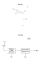
- FIG. 8A is a view showing an outer appearance according to the embodiment 500 of the object or reference lighting device 200 exemplarily shown in FIG. 1
- FIG. 8B is a block diagram schematically showing an embodiment, designated by reference numeral 510A, of a control box 510 exemplarily shown in FIG. 8A .
- the object or reference lighting device 500 may be a street light.
- the lighting device 500 exemplarily shown in FIG. 8A may include a post 540, a plurality of solar cell modules 530 installed to an upper surface of an upper end of the post 540, the control box 510 to control the lighting device 500 upon receiving an object brightness control signal transmitted in a wired or wireless manner from the object lighting control device 100 X , and a street light head 520 fixedly mounted to face the ground.
- a separate LED module (not shown) may be fitted inside a lower surface of the street light head 520.
- the control box 510A of the lighting device 500 includes an antenna 512, a control signal receiver 514, and a brightness controller 516.
- the object brightness control signal transmitted from the object lighting control device 100x is received by the control signal receiver 514 through the antenna 512.
- the control signal receiver 514 stores an inherent identification number (hereinafter referred to as 'object identification number') of the object lighting control device 100x, and judges whether or not the received object brightness control signal is transmitted from the object lighting control device 100x corresponding to the stored object identification number. This serves to ensure that the object lighting device 200, 500 is controlled only by the dedicated object lighting control device 100x.
- a header of the object brightness control signal may be provided with the object identification number.
- the object lighting device 200, 500 is controlled by the reference lighting control device 100 Y instead of the object lighting control device 100 X , an inherent identification number (hereinafter referred to as 'reference identification number') of the reference lighting control device 100 Y is previously transmitted to the control signal receiver 514.
- a reference brightness control signal serving as the object brightness control signal
- the control signal receiver 514 judges whether or not the reference brightness control signal is transmitted from the reference lighting control device 100 Y corresponding to the reference identification number.
- a header of the reference brightness control signal may be provided with the reference identification number.
- the control signal receiver 514 removes noises that may be included in the received object brightness control signal or amplifies a signal level to thereby output the resulting signal to the brightness controller 516.
- the brightness controller 516 converts an output of the control signal receiver 514 into a signal suitable to drive the LED module, and outputs the converted signal to the LED module via an output terminal OUT.
- the lighting device 500 as exemplarily shown in FIG. 8A acquires required power via the solar cell modules 530.
- the solar cell modules 530 are general items, and thus a detailed description thereof will be omitted herein.
- the lighting device 500 may acquire power from any other natural energy, such as, for example, hydroelectric energy, wind power, wave power, tidal power, ocean thermal energy conversion, or combinations thereof.
- the lighting device 500 may receive required power from an alternative energy source, a fuel cell, or a commercial power source except for the enumerated natural energy sources.
- the object lighting control device 100 X may further include the object storage unit 132 X
- the reference lighting control device 100 Y may further include the reference storage unit 132 Y .
- the object storage unit 132 X stores the calibration number of at least one of an object illuminance and an object brightness. That is, the object storage unit 132 X stores the implementation number of Operation 270.
- the number of times stored in the object storage unit 132 X may be transmitted to a central control room (not shown) so as to be used later for management, such as maintenance/repair/cleaning of the object lighting device 200, for example.
- the central control room may check the presence/absence of foreign materials in the object lighting control device 100 X based on the implementation number of Operation 270, which may allow a corresponding lighting device to be cleaned upon regular inspection.
- checking the detection frequency of foreign materials in the object lighting control device 100 X based on the implementation number of Operation 270 may ensure easy detection of the object lighting control device 100 X having a high generation frequency of foreign materials, which may help removal or avoidance of the cause of frequent generation of foreign materials.
- the lighting control system exemplarily shown in FIG. 2 may allow the reference lighting control device 100 Y to control the object lighting device 200, rather than calibrating at least one of the object illuminance and the object brightness as described above with reference to FIG. 3 .
- an object brightness of the object lighting device 200 may differ from a reference brightness of the reference lighting device 200 due to an error. Accordingly, embodiment 500 exemplarily shown in FIG. 6 may be performed after implementation of embodiment 400 exemplarily shown in FIG. 4 .
- FIG. 9 is a graph showing variation 610 in hourly sunlight illuminance, variation 620 in normal brightness of the lighting device 200, and variation 630 in abnormal brightness of the lighting device 200 by foreign materials.
- the object lighting device 200 provided in the object district 200 X is normally operated as follows.
- the object illuminance sensing unit 110 X senses the lowest sunlight illuminance 610.
- the object control unit 130x generates an object brightness control signal in response to the sensed result of the object illuminance sensing unit 110 X , and the object lighting device 200 is turned on in response to the object brightness control signal, thereby emitting light so as to maintain a constant level of brightness LV around the object lighting device 200 (620).
- the object illuminance sensing unit 110 X senses a gradually increasing sunlight illuminance 610.
- the object lighting device 200 emits gradually darker light so as to maintain a constant level of brightness LV around the object lighting device 200 (620).
- the object illuminance sensing unit 110 X senses a gradually decreasing sunlight illuminance 610.
- the object lighting device 200 emits gradually brighter light so as to maintain a constant level of brightness LV around the object lighting device 200 (620).
- the object illuminance sensing unit 110 X senses a sunlight illuminance 610.
- the lighting device 200 is turned off without emission of light because a constant level of brightness LV is maintained around the object lighting device 200 by sunlight (620).
- the object lighting device 200 provided in the object district 200x may be abnormally operated as follows.
- the object illuminance sensing unit 110 X During the sunrise duration t 1 -t 3 from the beginning to the end of sunrise, the object illuminance sensing unit 110 X , a light receiving area of which is reduced due to foreign materials, retardedly senses variation in sunlight illuminance 610. Thereby, under control of the object control unit 130 X , the object lighting device 200 emits gradually dimmer light starting from a time point t 2 that is slightly later than the time point t 1 (630). That is, the object lighting device 200 exhibits abnormal light emission for a duration t 1 ⁇ 1 2 . Moreover, the object lighting device 200 is turned off at a time point t 4 that is slightly later than the time point t 3 . That is, the object lighting device 200 unnecessarily remains powered-on, rather than being turned off, for a duration t 3 ⁇ t 4 , which results in excess power consumption.
- the object illuminance sensing unit 110 X may sense variation in sunlight illuminance 610 as if sunset begins, before the sunset duration from the beginning to the end of sunset t 6 ⁇ t 8 .
- the object lighting device 200 is turned on at a time point t 5 that is slightly earlier than the time point t 6 (630). That is, the object lighting device 200 may unnecessarily emit light for a duration t 5 ⁇ t 6 , which results in excess power consumption.
- the lighting device 200 emits gradually brighter light for a duration t 5 to t 7 so as to maintain a constant level of brightness LV around the object lighting device 200 (620).
- a time point when a brightness level begins to increase is slightly fast and thus a greater quantity of power than in the normal case is consumed for a duration t 6 ⁇ t 7 .
- the object lighting control device 100x utilizes reference data as well as an object illuminance in order to generate an object brightness control signal for control of the object lighting device 200. Accordingly, as described above with reference to FIG. 9 , it is possible to prevent unnecessary power consumption and reduction in the lifespan of the object lighting device 200 caused when the object lighting device 200 emits light for an increased duration as the object illuminance sensing unit 110 X senses variation in sunlight illuminance 610 early or late due to foreign materials.
- FIG. 10 is a graph showing a relationship between a duty ratio of a PWM object brightness control signal and brightness of sunlight.
- the object lighting control device 100 X generates an object brightness control signal 730 at the time point t 6 that is later than the time point t 5 (Duty 0%), so as to allow the object lighting device 200 to emit light.
- the object lighting control device 100 X generates an object brightness control signal 720 (Duty 0%) so as to allow the object lighting device 200 to emit light.
- an object brightness control signal 720 Duty 0%
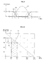
- FIGs. 11 and 12 are graphs showing a relationship between a duty ratio of a PWM object brightness control signal and brightness of sunlight.
- the presence of impurities causes the object lighting device 200 to be abnormally operated by a striped area 830 in the graph due to a difference between an object illuminance 810 sensed by the object illuminance sensing unit 110 X and a reference illuminance 820 sensed by the reference illuminance sensing unit 110 Y , which results in unnecessary power consumption.
- an object illuminance S 1 910 output from the object illuminance sensing unit 110 X in which foreign materials are present is calibrated using a reference illuminance S A 920, it is possible to prevent abnormal operation of the object lighting device 200 because a duty ratio of the object brightness control signal moves from 0% in an arrow direction.
- an object lighting control device of a lighting control system may accurately control an object lighting device by referring to a reference lighting control device in the case in which a light receiving area of an illuminance sensing unit is reduced or blocked due to foreign materials, which may prevent unnecessary power consumption, and result in increased lifespan of the object lighting device and maintenance/repair cost savings.
Landscapes
- Circuit Arrangement For Electric Light Sources In General (AREA)
Abstract
Description
- Embodiments relate to a lighting control system.
- In general, conventional lighting control systems to control lighting devices, such as street lights, are designed to sense an illuminance around a lighting device using an illuminance sensor (not shown), and thereafter to control the lighting device according to the sensed illuminance.
- The illuminance sensor, however, may fail to accurately sense an illuminance around the lighting device if a light receiving area thereof is reduced or covered by foreign materials, such as fallen leaves, bird guano, dust, etc. This may cause a lighting device, such as a street light, to malfunction, by, for example, turning on before sunset and failing to turn off after sunrise, thereby shortening lifespan and unnecessarily consuming power. In addition, removal of foreign materials from the illuminance sensor may require frequent cleaning of the illuminance sensor, which may increase maintenance/repair costs of the lighting device.
- Embodiments provide a lighting control system, which may more accurately control lighting devices without being influenced by foreign materials.
- In one embodiment, a lighting control system includes an object lighting control device that generates an object brightness control signal to control an object brightness of an object lighting device provided in an object district using a sensed result of an object illuminance around the object lighting device and using reference data, and at least one reference lighting control device that generates a reference brightness control signal to control a reference brightness of a reference lighting device provided in a reference district using a sensed result of a reference illuminance around the reference lighting device, and that transmits at least one of the reference illuminance and the reference brightness as the reference data to the object lighting control device in response to a request of the object lighting control device.
- The object lighting control device may calibrate at least one of the object illuminance and the object brightness using at least one of an illuminance comparison result between the object illuminance and the reference illuminance and a brightness comparison result between the reference brightness and the object brightness, and the object lighting control device may generate the object brightness control signal using at least one of the calibrated object illuminance and object brightness.
- The object lighting control device may calibrate the object illuminance using the reference illuminance when the illuminance comparison result shows that a difference between the object illuminance and the reference illuminance diverges from a first allowable deviation range.
- The object lighting control device may calibrate the object illuminance by performing the following calculation at least one time until a deviation between an average value of the object illuminance and the reference illuminance and the reference illuminance enters the first allowable deviation range:

(where, K is a positive integer of 1 or more, which corresponds to the implementation number of the above calculation and denotes a calibration number, SK denotes the calibrated object illuminance, and S0(K=1) is the object illuminance to be calibrated, and SA denotes the reference illuminance). - The object lighting control device may calibrate the object brightness using the reference brightness if the brightness comparison result shows that a difference between the object brightness and the reference brightness diverges from a second allowable deviation range.
- The object lighting control device may calibrate the object brightness by performing the following calculation at least one time until a difference between the calibrated object brightness and the reference brightness enters the second allowable deviation range:

(where, M is a positive integer of 1 or more, which corresponds to the implementation number of the above calculation and denotes a calibration number, BM denotes the calibrated object illuminance, B0(M=1) denotes the object brightness to be calibrated, and BA denotes the reference brightness). - The at least one reference lighting control device may include a plurality of reference lighting control devices, and the object lighting control device may calibrate the object illuminance using an average value of a plurality of reference illuminances sensed by the plurality of reference lighting control devices.
- The at least one reference lighting control device may include a plurality of reference lighting control devices, and the object lighting control device may calibrate the object brightness using an average value of a plurality of reference brightnesses output from the plurality of reference lighting control devices.
- The at least one reference lighting control device may include a plurality of reference lighting control devices, and the object lighting control device may calibrate the object illuminance using an average value of highest-frequency reference illuminances among a plurality of reference illuminances sensed by the plurality of reference lighting control devices.
- The at least one reference lighting control device may include a plurality of reference lighting control devices, and the object lighting control device may calibrate the object brightness using an average value of highest-frequency reference brightnesses among a plurality of reference brightnesses output from the plurality of reference lighting control devices.
- The object lighting control device may transmit a lighting control request signal in response to at least one of the illuminance comparison result and the brightness comparison result, and the reference lighting control device may transmit the reference brightness control signal as the object brightness control signal to the object lighting device in response to the lighting control request signal.
- The object lighting control device may transmit an inherent identification signal of the reference lighting control device to the object lighting device when transmitting the lighting control request signal to the reference lighting control device, and wherein the object lighting device may allow control of the reference lighting control device that is recognized based on the identification signal.
- The object lighting control device may include an object illuminance sensing unit configured to sense the object illuminance, an object control unit configured to generate the object brightness control signal using the sensed object illuminance and the reference data, and an object communication unit configured to transmit the object brightness control signal to the object lighting device.
- The object lighting control device may further include an object signal conversion unit that amplifies the object illuminance sensed by the object illuminance sensing unit and convert a form of the object illuminance into a form of voltage or frequency and that outputs the converted object illuminance, and the object control unit may generate the object brightness control signal using the converted object illuminance and the reference data.
- The object control unit may generate the object brightness control signal in the form of a pulse width modulation signal.
- The reference lighting control device may include a reference illuminance sensing unit configured to sense the reference illuminance, a reference control unit configured to generate the reference brightness control signal using the sensed reference illuminance, and a reference communication unit configured to transmit the reference brightness control signal to the reference lighting device.
- The reference lighting control device may further include a reference signal conversion unit that amplifies the reference illuminance sensed by the reference illuminance sensing unit and converts a form of the reference illuminance into a form of voltage or frequency and that outputs the converted reference illuminance, and the reference control unit may generate the reference brightness control signal using the converted reference illuminance.The object lighting control device may further include a storage unit configured to store the implementation number of calibration of at least one of the object illuminance and the object brightness.
- The lighting control system may manage the object lighting device using the implementation number of calibration stored in the storage unit.
- In another embodiment, a lighting control system includes an object lighting control device that generates a lighting control request signal using a sensed result of an object illuminance around an object lighting device provided in an object district and using reference data, and a reference lighting control device that generates a reference brightness control signal to control a reference brightness of a reference lighting device provided in a reference district using a sensed result of a reference illuminance around the reference lighting device, and that outputs the reference brightness control signal as an object brightness control signal to control a brightness of the object lighting device to the object lighting control device in response to the lighting control request signal received from the object lighting control device.
- Arrangements and embodiments may be described in detail with reference to the following drawings in which like reference numerals refer to like elements and wherein:
-
FIG. 1 is a layout diagram of a lighting control system and a lighting device according to an embodiment; -
FIG. 2 is a schematic block diagram of a lighting control system according to an embodiment; -
FIG. 3 is a flowchart explaining a lighting control method that is performed by the lighting control system according to an embodiment; -
FIG. 4 is a flowchart explaining one embodiment ofOperation 270 inFIG. 3 ; -
FIG. 5 is a graph showing a reference illuminance and a calibrated object illuminance with respect to a calibration number according to an embodiment; -
FIG. 6 is a flowchart explaining another embodiment ofOperation 270 inFIG. 3 ; -
FIG. 7 is a graph showing a reference brightness and a calibrated object brightness with respect to a calibration number according to an embodiment; -
FIG. 8A is a view showing an outer appearance of an embodiment of an object or reference lighting device exemplarily shown inFIG. 1 , andFIG. 8B is a block diagram schematically showing an embodiment of a control box exemplarily shown inFIG. 8A ; -
FIG. 9 is a graph respectively showing variation in hourly sunlight illuminance, variation in the normal brightness of a lighting device, and variation in the abnormal brightness of a lighting device; -
FIG. 10 is a graph showing a relationship between a duty ratio of a PWM object brightness control signal and brightness of sunlight; and -
FIGs. 11 and 12 are graphs showing a relationship between a duty ratio of a PWM object brightness control signal and brightness of sunlight. - Hereinafter, embodiments will be described to help understanding of the present disclosure with reference to the accompanying drawings. However, the embodiments may be embodied in many alternate forms and should not be construed as limited to the embodiments set forth herein. Rather, these embodiments are provided so that this disclosure will be thorough and complete and will fully convey the scope to those skilled in the art.
-
FIG. 1 is a layout diagram of a lighting control system and a lighting device according to an embodiment. - Referring to
FIG. 1 , the lighting control system according to the embodiment is comprised of first to Nthlighting control devices 1001 to 100N. Here, N is a positive integer of 1 or more. The first to Nthlighting control devices 1001 to 100N are respectively allotted to first to Nth districts 2001 to 200N. Each of the first to Nth districts 2001 to 200N is provided with at least onelighting device 200. The at least onelighting device 200 provided in each district is controlled by first to Nth brightness control signals L1 to LN which are generated respectively by the correspondinglighting control devices 1001 to 100N. - That is, the first
lighting control device 1001 is allotted to thefirst district 2001, and at least onelighting device 200 provided in thefirst district 2001 is controlled by the first brightness control signal L1. Similarly, the nthlighting control device 100n is allotted to the nth district 200n, and at least onelighting device 200 provided in the nth district 200N is controlled by the nth brightness control signal LN. Here, 1≤n≤N. - Hereinafter, in the lighting control system exemplarily shown in
FIG. 1 , a lighting control device that is an object of interest among the first to Nthlighting control devices 1001 to 100N is referred to as 'object lighting control device 100x' (here, 1≤X≤N), and another lighting control device that is referred to by the objectlighting control device 100x is referred to as 'reference lighting control device 100Y' (here, X≠Y, 1≤Y≤N). - To prevent the
lighting device 200 from being abnormally controlled due to a sensing error of an illuminance around thelighting device 200, the sensing error being caused by foreign materials, such as, for example, fallen leaves, bird guano, and/or dust, the objectlighting control device 100X may control thelighting device 200 as follows by referring to the referencelighting control device 100Y. - Hereinafter, a configuration and operation with regard to the case in which the object
lighting control device 100X refers to the referencelighting control device 100Y and the referencelighting control device 100Y is referred to by the objectlighting control device 100X will be described. Of course, the objectlighting control device 100X and the referencelighting control device 100Y may have the same configuration and may perform the same operation. -
FIG. 2 is a schematic block diagram of a lighting control system according to an embodiment, which includes the objectlighting control device 100X and the referencelighting control device 100Y. - The object
lighting control device 100x as exemplarily shown inFIG. 2 may include an object illuminance sensing unit 110X, an object signal conversion unit 120X, anobject control unit 130x, anobject communication unit 140x, and anobject antenna 150X, and may further include anobject storage unit 132X. - The object illuminance sensing unit 110X serves to sense an illuminance (hereinafter referred to as 'object illuminance') around at least one lighting device 200 (hereinafter referred to as 'object lighting device') that is provided in the Xth district 200x (hereinafter referred to as 'object district') among the first to Nth districts 2001 to 200N. Here, since the object
lighting control device 100x is located close to theobject lighting device 200, it is assumed that that an illuminance sensed by the object illuminance sensing unit 110X included in the objectlighting control device 100X substantially equals an illuminance around theobject lighting device 200 provided in theobject district 200X. For example, the object illuminance sensing unit 110X may function to change light into electricity and to output an object illuminance signal corresponding to the electricity. - The object signal conversion unit 120X may convert the form of the object illuminance transmitted from the object illuminance sensing unit 110X into voltage or frequency by amplifying the object illuminance, and output the object illuminance having the converted form to the
object control unit 130x. Here, the original form of the object illuminance may be voltage. - The object control unit 130X generates a brightness control signal (hereinafter referred to as 'object brightness control signal') using reference data and an object illuminance output from the object signal conversion unit 120X. Here, the reference data includes at least one of a reference illuminance and a reference brightness. The reference illuminance means an illuminance around the lighting device (hereinafter referred to as 'reference lighting device') provided in at least one district 200Y (hereinafter referred to as 'reference district'), different from the object district 200x, among the first to Nth districts 2001 to 200N. In addition, the reference brightness means a brightness (or luminance) of the
reference lighting device 200. - Additionally, according to an embodiment, the object control unit 130X calibrates at least one of an object illuminance and an object brightness using at least one of an illuminance comparison result and a brightness comparison result. Here, the object brightness means a brightness of the
object lighting device 200. In addition, the illuminance comparison result means a result of comparing an object illuminance with a reference illuminance, and the brightness comparison result means a result of comparing an object brightness with a reference brightness. This comparison may be performed by the object control unit 130X. - The
object control unit 130x may further function to detect the level of an object illuminance output from the objectsignal conversion unit 120x, and to generate a Pulse Width Modulation (PWM) object brightness control signal having a pulse width (or duty) corresponding to the detected level. In this case, the aforementioned object brightness control signal may take the form of digital data corresponding to a pulse duty ratio. Conversion from a PWM signal into digital data may be performed by the object control unit 130X via a prestored algorithm. - If the
object lighting device 200 is implemented by Light Emitting Diodes (LEDs), a brightness degree of the LEDs may vary according to a duty ratio of the PWM object brightness control signal. - Hereinafter, although the object
lighting control device 100X is connected in a wireless manner to theobject lighting device 200 provided in theobject district 200X and/or the referencelighting control device 100Y through theobject communication unit 140X and theobject antenna 150X, the embodiment is not limited thereto. That is, the objectlighting control device 100X may be connected in a wired manner to theobject lighting device 200 provided in the object district 200x and/or the referencelighting control device 100Y. If the objectlighting control device 100X is connected in a wired manner to theobject lighting device 200, theobject antenna 150X is omitted. - For example, the
object communication unit 140X may transmit an object brightness control signal, generated by the object control unit 130X, to theobject lighting device 200 through theobject antenna 150X using short-range wireless communication, such as RF wireless communication or ZigBee wireless communication. - The reference
lighting control device 100Y may include a reference illuminance sensing unit 110Y, a reference signal conversion unit 120Y, a reference control unit 130Y, areference communication unit 140Y, and areference antenna 150Y, and may further include areference storage unit 132Y. Here, to distinguish between the objectlighting control device 100x and the referencelighting control device 100Y, although the reference illuminance sensing unit 110Y, the reference signal conversion unit 120Y, the reference control unit 130Y, thereference communication unit 140Y, thereference antenna 150Y, and thereference storage unit 132Y differ in name from the object illuminance sensing unit 110X, the object signal conversion unit 120X, the object control unit 130X, theobject communication unit 140X, theobject antenna 150x, and theobject storage unit 132x, they may perform the same functions. - The reference illuminance sensing unit 110Y serves to sense a reference illuminance around at least one
reference lighting device 200 that is provided in thereference district 200Y among the first to Nth districts 2001 to 200N. - The reference signal conversion unit 120Y may convert the form of the reference illuminance into voltage or frequency via amplification of the reference illuminance sensed by the reference illuminance sensing unit 110Y and output the converted reference illuminance to the reference control unit 130Y.
- The reference control unit 130Y generates a brightness control signal (hereinafter referred to as 'reference brightness control signal') using a sensed reference illuminance result. In this case, the aforementioned reference brightness may be proportional to the level of a reference brightness control signal. That is, the
reference lighting device 200 may emit light having brightness corresponding to the level of a reference brightness control signal. In addition, the reference control unit 130Y may transmit at least one of a reference illuminance and a reference brightness as the reference data to the objectlighting control device 100X in response to a request of the objectlighting control device 100X. - The
reference communication unit 140Y and thereference antenna 150Y serve to transmit a reference brightness control signal, generated by the reference control unit 130Y, to thereference lighting device 200. - Although only one reference
lighting control device 100Y is exemplarily shown inFIG. 2 , at least one additional referencelighting control device 100Y having a configuration as exemplarily shown inFIG. 2 among the first to Nthlighting control devices 1001 to 100N may be present. That is, the objectlighting control device 100X may refer to a plurality of referencelighting control devices 100Y. - Hereinafter, detailed operations of the object
lighting control device 100x and the referencelighting control device 100Y will be described with reference to the accompanying drawings. -
FIG. 3 is a flowchart explaining a lighting control method that is performed by the lighting control system according to an embodiment. - Referring to
FIG. 3 , an object illuminance is detected (Operation 210). To this end, the object illuminance sensing unit 110X senses an object illuminance around theobject lighting device 200, and the object signal conversion unit 120X amplifies the sensed object illuminance into the form of voltage or frequency and outputs the amplifying result as the detected object illuminance to theobject control unit 130x. - After
Operation 210, the object control unit 130X generates and transmits an interrupt signal to at least one referencelighting control device 100Y through theobject communication unit 140X and the object antenna 150X (Operation 220). - After
Operation 220, the object control unit 130X requests the at least one referencelighting control device 100Y that permits the objectlighting control device 100X to access upon receiving the interrupt signal for reference data, i.e. at least one of a reference illuminance and a reference brightness (Operation 230). To this end, the object control unit 130X may transmit a signal that requests for at least one of a reference illuminance and a reference brightness to the referencelighting control device 100Y through theobject communication unit 140X and theobject antenna 150X. - After
Operation 230, the object control unit 130X of the objectlighting control device 100X may receive reference data, i.e. at least one of a reference illuminance and a reference brightness, from the referencelighting control device 100Y through theobject communication unit 140X and the object antenna 150X (Operation 240). - After
Operation 240, theobject control unit 130x may process the received reference data (operation 250). Theobject control unit 130x may process the received reference data in various ways as follows. - The
object control unit 130x may receive a plurality of reference illuminances from a plurality of referencelighting control devices 100Y, and may calculate an average value of the plurality of received reference illuminances. Here, the average value may be used to calibrate an object illuminance inOperation 270. - Alternatively, the object control unit 130X may calculate an average value of highest-frequency reference illuminances among a plurality of reference illuminances sensed by the plurality of reference
lighting control devices 100Y. Here, the average value may be used to calibrate an object illuminance inOperation 270, and a plurality of highest-frequency reference illuminances may be present. For example, if a place where thereference lighting device 200 is located is temporarily affected by, e.g., a cloud or a shadow of the surrounding building, a plurality of reference illuminances may significantly differ from one another with deviations therebetween. In consideration of this fact, an object illuminance may be calibrated using the average value of the highest-frequency reference illuminances among the plurality of reference illuminances. - Additionally, the object control unit 130X may receive a plurality of reference brightnesses output from a plurality of reference
lighting control devices 100Y, and may calculate an average value of the plurality of received reference brightnesses. Here, the average value may be used to calibrate an object brightness inOperation 270. - Alternatively, the object control unit 130X may calculate an average value of highest-frequency reference brightnesses among a plurality of reference brightnesses output from the plurality of reference
lighting control devices 100Y. Here, the average value may be used to calibrate an object brightness inOperation 270, and a plurality of highest-frequency reference brightnesses may be present. - If object illuminance (or object brightness) is calibrated using a reference illuminance (or reference brightness), instead of the average value, in
Operation 270,Operation 250 may be omitted. - After
Operation 250, the object control unit 130X judges whether or not to calibrate at least one of an object illuminance and an object brightness (Operation 260). - If foreign materials are present on a light receiving cover (not shown) of the object illuminance sensing unit 110X, a light receiving area of the object illuminance sensing unit 110X may be reduced or blocked.
- If the light receiving area is blocked by foreign materials, the object
lighting control device 100X may allow the referencelighting control device 100Y to directly control theobject lighting device 200, instead of calibrating at least one of an object illuminance and an object brightness (Operation 290). To this end, the object control unit 130X generates and outputs a lighting control request signal to the referencelighting control device 100Y, and the referencelighting control device 100Y transmits a reference brightness control signal serving as an object brightness control signal to theobject lighting device 200 in response to the lighting control request signal. That is, the referencelighting control device 100Y instead of the objectlighting control device 100X controls theobject lighting device 200. In this case, when transmitting the lighting control request signal to the referencelighting control device 100Y, the object control unit 130X may transmit an inherent identification signal of the referencelighting control device 100Y to theobject lighting device 200. This serves to allow theobject lighting device 200 to be controlled by the referencelighting control device 100Y corresponding to the received identification signal. - However, if it is recognized that the light receiving area is not blocked, but is reduced, the object control unit 130X may calibrate at least one of an object illuminance and an object brightness (Operation 270).
- To perform
Operation 260, the object control unit 130X may use at least one of an illuminance comparison result and a brightness comparison result. For example, if it is recognized from an illuminance comparison result that a difference between an object illuminance and a reference illuminance is continuously maintained for a predetermined duration or more, the object control unit 130X may performOperation 290 based on judgment that the light receiving area is blocked. In addition, if it is recognized from a brightness comparison result that a difference between an object brightness and a reference brightness is continuously maintained for a predetermined duration or more, the object control unit 130X may performOperation 290 based on judgment that the light receiving area is blocked. Although duration from sunset till sunrise in the summer season differs from duration from sunset till sunrise in the winter season, such difference is not over a predetermined duration. Accordingly, if a difference between an object illuminance and a reference illuminance or a difference between an object brightness and a reference brightness is continuously maintained for the predetermined duration or more, it may be judged that the light receiving area is blocked by foreign materials. - On the other hand, if it is recognized from an illuminance comparison result that a difference between an object illuminance and a reference illuminance is not continuously maintained for the predetermined duration or more, the object control unit 130X may proceed to
Operation 270 without generating a lighting control request signal based on judgment that the light receiving area is not blocked, but is reduced. In addition, if it is recognized from a brightness comparison result that a difference between an object brightness and a reference brightness is not continuously maintained for the predetermined duration or more, theobject control unit 130x may proceed toOperation 270 without generating a lighting control request signal based on judgment that the light receiving area is not blocked, but is reduced. If a difference between an object illuminance and a reference illuminance or a difference between an object brightness and a reference brightness is not continuously maintained for the predetermined duration or more, this means that the light receiving area is not blocked by foreign materials. - In a state in which the light receiving area is not blocked, the
object control unit 130x may calibrate at least one of an object illuminance and an object brightness using reference data (operation 270). That is, the object control unit 130X may calibrate an object illuminance using a reference illuminance, and may calibrate an object brightness using a reference brightness. -
FIG. 4 is a flowchart explaining one embodiment, designated byreference numeral 300, ofOperation 270 inFIG. 3 . - In the
embodiment 300 as exemplarily shown inFIG. 4 , the object control unit 130X calibrates an object illuminance S1 using a reference illuminance SA when an illuminance comparison result shows that a difference between the object illuminance S1 and the reference illuminance SA diverges from a first allowable deviation range (Operations 310 to 360). Hereinafter, although the reference illuminance SA will be described as serving to calibrate the object illuminance S1, the following description will be directly applied even in the case in which, instead of the reference illuminance SA, an average value of a plurality of reference illuminances is used, or an average value of highest-frequency reference illuminances among a plurality of reference illuminances is used. - First, the
object control unit 130x judges whether or not a difference between the object illuminance S1 and the reference illuminance SA diverges from the first allowable deviation range (Operations 310 and 320). - More specifically, the object control unit 130X judges whether or not the object illuminance S1 is equal to or greater than the reference illuminance SA (operation 310). If it is judged that the object illuminance S1 is equal to or greater than the reference illuminance SA, calibration of the object illuminance S1 is not performed (Operation 360).
- However, if it is judged that the object illuminance S1 is less than the reference illuminance SA, the object control unit 130X judges whether or not a difference (or ratio) between the object illuminance S1 and the reference illuminance SA diverges from the first allowable deviation range (Operation 320). Assuming that the
lighting device 200 exemplarily shown inFIG. 1 is implemented by LEDs, the first allowable deviation range may be within a range of 0.9 to 0.99 because a lighting deviation rate of LEDs is approximately in a range of 0 to 10%. - That the object illuminance S1 sensed by the object illuminance sensing unit 110X is less than the reference illuminance SA sensed by the reference illuminance sensing unit 110Y means that it is possible for the object illuminance sensing unit 110X not to accurately sense an illuminance around the
object lighting device 200 due to the influence of foreign materials, such as fallen leaves, bird guano, dust, or the like. - To accurately identify this possibility, a degree of the difference (or ratio) between the object illuminance S1 and the reference illuminance SA is checked (Operation 320). To this end, as exemplarily shown in
FIG. 4 , it may be judged that a ratio of the object illuminance S1 to the reference illuminance SA is a first allowable deviation or more, for example, is 0.99 or more (Operation 320). - If it is judged that a difference between the object illuminance S1 and the reference illuminance SA is within the first allowable deviation range, calibration of the object illuminance S1 is not performed (Operation 360). For example, assuming that the object illuminance S1 is 0.999, the reference illuminance SA is 1, and the first allowable deviation is 0.99, the object illuminance S1 is less than the reference illuminance SA, but a value of S1/SA is 0.999, greater than the first allowable deviation of 0.99, and therefore calibration of the object illuminance S1 is not performed (Operation 360). As described above, that a difference between the object illuminance S1 and the reference illuminance SA is within the first allowable deviation range and is close to the first allowable deviation means that a reduction in the light receiving area due to foreign materials, etc. is extremely slight, and thus a deviation of the object illuminance S1 with respect to the reference illuminance SA is extremely slight. Therefore, calibration of the object illuminance S1 is unnecessary.
- However, if it is judged that a difference between the object illuminance S1 and the reference illuminance SA diverges from the first allowable deviation range, the object illuminance S1 is calibrated using the reference illuminance SA (
Operations 330 to 350). - For example, the object control unit 130X may calibrate the object illuminance S1 by performing calculation as represented by the following
Equation 1 at least one time until a deviation between an average value of the object illuminance S1 and the reference illuminance and the reference illuminance enters the first allowable deviation range (Operation 330).
- Here, K is a positive integer of 1 or more, which corresponds to the implementation number of calculation of the
aforementioned Equation 1 in order to acquire a calibrated object illuminance, and denotes a calibration number. In addition, S0(K=1) is S1, and SK denotes a calibrated object illuminance. - It is judged whether or not a ratio of the calibrated object illuminance S1, derived via calculation of
Equation 1, to the reference illuminance SA is the first allowable deviation or more, for example, is 0.99 or more (Operation 340). As such, calculation ofEquation 1 is successively performed K times until a value of SK/SA becomes the first allowable deviation or more. - If the value of SK/SA becomes the first allowable deviation or more, a value of SK acquired after performing calculation of Equation 1 K times is set to a final value of the calibrated object luminance (Operation 350).
-
FIG. 5 is a graph showing a reference illuminance SA and a calibrated object illuminance SK with respect to a calibration number K according to an embodiment. - For example, assuming that an average reference illuminance value is "1000" and an object illuminance S1 sensed under the influence of foreign materials is "750", as exemplarily shown in Table 1, a difference between a calibrated object illuminance SK and a reference illuminance SA reaches the first allowable deviation, i.e. 0.99 when the object illuminance SK-1 and the reference illuminance SA are calculated 5 times based on Equation 1 (that is, K=5).
Table 1 Calibration number (K) Reference illuminance (SA) Object illuminance to be calibrated (S1) SK-1+SA Calibrated object Illuminance (SK) Deviation rate (%) (SK-1+SA)/2 1 1000 750 1750 875 87.5 2 1875 937.5 93.75 3 1937.5 968.75 96.875 4 1968.75 984.375 98.4375 5 1984.375 992.1875 99.21875 6 1992.188 996.09375 99.60938 7 1996.094 998.046875 99.80469 8 1998.047 999.0234375 99.90234 9 1999.023 999.5117188 99.95117 10 1999.512 999.7558594 99.97559 11 1999.756 999.8779297 99.98779 12 1999.878 999.9389648 99.9939 - Here, S0 is 750.
- Referring to
FIG. 5 and Table 1, it will be appreciated that the calibrated object illuminance SK approaches to the reference illuminance SA as the calibration number K increases. -
FIG. 6 is a flowchart explaining another embodiment, designated byreference numeral 400, ofOperation 270 inFIG. 3 . - In the
embodiment 400 as exemplarily shown inFIG. 6 , the object control unit 130x calibrates an object brightness B1 using a reference brightness BA when a brightness comparison result shows that a difference between the object brightness B1 and the reference brightness BA diverges from a second allowable deviation range (Operations 410 to 460). - Hereinafter, although use of the reference brightness BA itself to calibrate the object brightness B1 will be described, the following description will be directly applied even in the case in which, instead of the reference brightness BA, an average value of a plurality of reference brightnesses is used, or an average value of highest-frequency reference brightnesses among a plurality of reference brightnesses is used.
- First, the object control unit 130X judges whether or not a difference (or ratio) between the object brightness B1 and the reference brightness BA diverges from the second allowable deviation range (
Operations 410 and 420). - First, the
object control unit 130x judges whether or not the object brightness B1 is equal to or less than the reference brightness BA (operation 410). If it is judged from the brightness comparison result that the object brightness B1 is equal to or less than the reference brightness BA, the object control unit 130X does not calibrate the object brightness B1 (Operation 460). This is because if no foreign materials are present on the object illuminance sensing unit 110X, an illuminance around theobject lighting device 200 is accurately sensed and thus theobject lighting device 200 does not unnecessarily remain powered-on, whereby the object brightness B1 becomes the reference brightness BA or less. - However, if it is judged that the object brightness B1 is greater than the reference brightness BA, the object control unit 130X judges whether or not a difference between the object brightness B1 and the reference brightness BA diverges from the second allowable deviation range (Operation 420). That the object brightness B1 is greater than the reference brightness BA means that a brightness of the
object lighting device 200 controlled by the objectlighting control device 100X is greater than a brightness of thereference lighting device 200 controlled by the referencelighting control device 100Y. This may mean that a light receiving area is reduced due to foreign materials present on the objectilluminance sensing unit 100X. For example, although thereference lighting device 200 is turned off after sunrise, the object control unit 130X may keep theobject lighting device 200 powered-on because the object illuminance sensing unit 110X has no ability to accurately sense an object illuminance due to foreign materials. As such, theobject control unit 130x may detect the presence/absence of foreign materials by comparing a brightness of theobject lighting device 200 with a brightness of thereference lighting device 200. - To judge whether or not a difference between the object brightness B1 and the reference brightness BA diverges from the second allowable deviation range, as exemplarily shown in
FIG. 6 , the object control unit 130X judges whether or not a ratio of the reference brightness BA to the object brightness B1 is equal to or greater than a second allowable deviation. - If it is judged that a difference between the object brightness B1 and the reference brightness BA is within the second allowable deviation range, calibration of the object brightness B1 is not performed (Operation 460). That a difference between the object brightness B1 and the reference brightness BA is within the second allowable deviation range means that a deviation of the object brightness B1 with respect to the reference brightness BA is extremely slight, in other words, the quantity of foreign materials is slight. Therefore, calibration of the object brightness B1 is unnecessary.
- For example, assuming that the object brightness B1 is 1, an average reference brightness value BA is 0.999, and the second allowable deviation is 0.99, the object brightness B1 is greater than the reference brightness BA, but an error between B1 and BA, i.e. a value of BA/B1 is 0.999 that is greater than the second allowable range, i.e. 0.99, and therefore calibration of the object brightness B1 is not performed (Operation 460).
- However, if it is judged that a deviation between the object brightness B1 and the reference brightness BA diverges from the second allowable deviation range, the object brightness B1 is calibrated using the reference brightness BA (
Operations 430 to 450). - The object control unit 130X may calibrate the object brightness B1 by performing calculation as represented by the following
Equation 2 at least one time until a difference between a calibrated object brightness and a reference brightness enters the second allowable deviation range (Operations 430 and 440).
- Here, M is a positive integer of 1 or more, which corresponds to the implementation number of calculation of the
aforementioned Equation 2, and denotes a calibration number. In addition, B0(M=1) is B1, and BM denotes a calibrated object illuminance. - It is judged whether or not a ratio of the reference brightness BA to the object brightness BM calibrated by successively performing calculation of
Equation 2 is the second allowable deviation or more, for example, is 0.99 or more (Operation 440). As such, calculation ofEquation 2 is successively performed M times until a value of BA/BM becomes the second allowable deviation or more. - If the value of BA/BM becomes the second allowable deviation or more, a value of BM derived by performing calculation of Equation 2 M times is set to a final value of the calibrated object brightness (Operation 450).
-
FIG. 7 is a graph showing a reference brightness BA and a calibrated object brightness BM with respect to a calibration number M according to an embodiment. - For example, assuming that an average reference brightness value (hereinafter referred to as 'reference brightness') is '15' and an object brightness B1 affected by foreign materials is "45", a deviation between a calibrated object brightness BM and the reference brightness BA reaches the second allowable deviation, i.e. 0.99 when the object brightness and the reference brightness BA are calculated 8 times based on Equation 2 (that is, M=8).
Table 2 Calibration number (M) Object brightness to be calibrated (B1) Reference brightness (BA) BM-1-BA (BM-1-BA)/2 Calibrated object brightness(BM) Deviation rate (%) [(BM-1-BM-1-BA)/2) 1 45 15 30 15 30 66.66667 2 15 7.5 22.5 75 3 7.5 3.75 18.75 83.3333 4 3.75 1.875 16.875 90 5 1.875 0.9375 15.9375 94.44444 6 0.9375 0.46875 15.46875 97.05882 7 0.46875 0.234375 15.23438 98.48485 8 0.234375 0.1171875 15.11719 99.23077 9 0.117188 0.0859375 15.05859 99.6124 10 0.058594 0.029296875 15.0293 99.80545 11 0.029297 0.014648438 15.0465 99.90253 12 0.014648 0.007324219 15.00732 99.95122 - Here, B0 is 45.
- Referring to
FIG. 7 and Table 2, it will be appreciated that the calibrated object brightness BM approaches the reference brightness BA as the calibration number M increases. - Meanwhile, after
Operation 270, the object control unit 130X generates an object brightness control signal using at least one of the calibrated object illuminance and the calibrated object brightness, and controls theobject lighting device 200 provided in theobject district 200X using the generated object brightness control signal (Operation 280). To this end, the object brightness control signal is transmitted to theobject lighting device 200 of theobject district 200X through theobject communication unit 140X and theobject antenna 150X. At least oneobject lighting device 200 provided in theobject district 200X may receive the object brightness control signal transmitted from the objectlighting control device 100X Then, the at least oneobject lighting device 200 may be turned on or off, or may adjust a brightness level thereof according to the received object brightness control signal. To this end, thelighting device 200 may be embodied in various ways. - Hereinafter, although an outer appearance, configuration, and operation of an embodiment, designated by
reference numeral 500, of thelighting device 200 exemplarily shown inFIG. 1 will be described with reference to the accompanying drawings, of course, the embodiment is not limited thereto, and thelighting device 200 may be embodied in various ways. -
FIG. 8A is a view showing an outer appearance according to theembodiment 500 of the object orreference lighting device 200 exemplarily shown inFIG. 1 , andFIG. 8B is a block diagram schematically showing an embodiment, designated byreference numeral 510A, of acontrol box 510 exemplarily shown inFIG. 8A . - As exemplarily shown in
FIG. 8A , the object orreference lighting device 500 may be a street light. Thelighting device 500 exemplarily shown inFIG. 8A may include apost 540, a plurality ofsolar cell modules 530 installed to an upper surface of an upper end of thepost 540, thecontrol box 510 to control thelighting device 500 upon receiving an object brightness control signal transmitted in a wired or wireless manner from the objectlighting control device 100X, and astreet light head 520 fixedly mounted to face the ground. A separate LED module (not shown) may be fitted inside a lower surface of thestreet light head 520. - Referring to
FIG. 8B , thecontrol box 510A of thelighting device 500 includes anantenna 512, acontrol signal receiver 514, and abrightness controller 516. The object brightness control signal transmitted from the objectlighting control device 100x is received by thecontrol signal receiver 514 through theantenna 512. In this case, thecontrol signal receiver 514 stores an inherent identification number (hereinafter referred to as 'object identification number') of the objectlighting control device 100x, and judges whether or not the received object brightness control signal is transmitted from the objectlighting control device 100x corresponding to the stored object identification number. This serves to ensure that theobject lighting device lighting control device 100x. To this end, a header of the object brightness control signal may be provided with the object identification number. - As described above, if the
object lighting device lighting control device 100Y instead of the objectlighting control device 100X, an inherent identification number (hereinafter referred to as 'reference identification number') of the referencelighting control device 100Y is previously transmitted to thecontrol signal receiver 514. Thus, when a reference brightness control signal, serving as the object brightness control signal, generated by the referencelighting control device 100Y is transmitted to theobject lighting device control signal receiver 514 judges whether or not the reference brightness control signal is transmitted from the referencelighting control device 100Y corresponding to the reference identification number. To this end, a header of the reference brightness control signal may be provided with the reference identification number. - The
control signal receiver 514 removes noises that may be included in the received object brightness control signal or amplifies a signal level to thereby output the resulting signal to thebrightness controller 516. Thebrightness controller 516 converts an output of thecontrol signal receiver 514 into a signal suitable to drive the LED module, and outputs the converted signal to the LED module via an output terminal OUT. - The
lighting device 500 as exemplarily shown inFIG. 8A acquires required power via thesolar cell modules 530. Thesolar cell modules 530 are general items, and thus a detailed description thereof will be omitted herein. Instead of using thesolar cell modules 530, thelighting device 500 may acquire power from any other natural energy, such as, for example, hydroelectric energy, wind power, wave power, tidal power, ocean thermal energy conversion, or combinations thereof. In addition, thelighting device 500 may receive required power from an alternative energy source, a fuel cell, or a commercial power source except for the enumerated natural energy sources. - Meanwhile, in the lighting control system as exemplarily shown in
FIG. 2 , the objectlighting control device 100X may further include theobject storage unit 132X, and the referencelighting control device 100Y may further include thereference storage unit 132Y. Theobject storage unit 132X stores the calibration number of at least one of an object illuminance and an object brightness. That is, theobject storage unit 132X stores the implementation number ofOperation 270. The number of times stored in theobject storage unit 132X may be transmitted to a central control room (not shown) so as to be used later for management, such as maintenance/repair/cleaning of theobject lighting device 200, for example. - The central control room may check the presence/absence of foreign materials in the object
lighting control device 100X based on the implementation number ofOperation 270, which may allow a corresponding lighting device to be cleaned upon regular inspection. In addition, checking the detection frequency of foreign materials in the objectlighting control device 100X based on the implementation number ofOperation 270 may ensure easy detection of the objectlighting control device 100X having a high generation frequency of foreign materials, which may help removal or avoidance of the cause of frequent generation of foreign materials. - Meanwhile, if it is judged from at least one of an illuminance comparison result and a brightness comparison result that foreign materials are present in the object illuminance sensing unit 110X, the lighting control system exemplarily shown in
FIG. 2 may allow the referencelighting control device 100Y to control theobject lighting device 200, rather than calibrating at least one of the object illuminance and the object brightness as described above with reference toFIG. 3 . - Although the above description exemplifies calibration of an object illuminance using a reference illuminance, an object brightness of the
object lighting device 200 may differ from a reference brightness of thereference lighting device 200 due to an error. Accordingly,embodiment 500 exemplarily shown inFIG. 6 may be performed after implementation ofembodiment 400 exemplarily shown inFIG. 4 . -
FIG. 9 is agraph showing variation 610 in hourly sunlight illuminance,variation 620 in normal brightness of thelighting device 200, andvariation 630 in abnormal brightness of thelighting device 200 by foreign materials. Although the following description is based on sunset or sunrise, of course, the following description is also applicable to an environment similar to sunset or sunrise. - If no foreign materials are present in the object illuminance sensing unit 110X, the
object lighting device 200 provided in theobject district 200X is normally operated as follows. - Referring to
FIG. 9 , during nighttime t8~t1 after the end of sunset t8 and before the beginning of sunrise t1, the object illuminance sensing unit 110X senses thelowest sunlight illuminance 610. In this case, theobject control unit 130x generates an object brightness control signal in response to the sensed result of the object illuminance sensing unit 110X, and theobject lighting device 200 is turned on in response to the object brightness control signal, thereby emitting light so as to maintain a constant level of brightness LV around the object lighting device 200 (620). - During a sunrise duration t1~t3 from a time point t1 when sunrise begins till a time point t3 when sunrise is completed, the object illuminance sensing unit 110X senses a gradually increasing
sunlight illuminance 610. In this case, under control of the object brightness control signal generated from theobject control unit 130x, theobject lighting device 200 emits gradually darker light so as to maintain a constant level of brightness LV around the object lighting device 200 (620). - In addition, during a sunset duration t6~t8 from a time point t6 when sunset begins till a time point t8 when sunset is completed, the object illuminance sensing unit 110X senses a gradually decreasing
sunlight illuminance 610. In this case, under control of the object brightness control signal generated from theobject control unit 130x, theobject lighting device 200 emits gradually brighter light so as to maintain a constant level of brightness LV around the object lighting device 200 (620). - During daytime after the end of sunrise t3 and before the beginning of sunset t6, the object illuminance sensing unit 110X senses a
sunlight illuminance 610. During the daytime, under control of the object brightness control signal generated by the object control unit 130X, thelighting device 200 is turned off without emission of light because a constant level of brightness LV is maintained around theobject lighting device 200 by sunlight (620). - Meanwhile, if foreign materials are present in the object illuminance sensing unit 110X, the
object lighting device 200 provided in the object district 200x may be abnormally operated as follows. - During the sunrise duration t1-t3 from the beginning to the end of sunrise, the object illuminance sensing unit 110X, a light receiving area of which is reduced due to foreign materials, retardedly senses variation in
sunlight illuminance 610. Thereby, under control of the object control unit 130X, theobject lighting device 200 emits gradually dimmer light starting from a time point t2 that is slightly later than the time point t1 (630). That is, theobject lighting device 200 exhibits abnormal light emission for a duration t1~12. Moreover, theobject lighting device 200 is turned off at a time point t4 that is slightly later than the time point t3. That is, theobject lighting device 200 unnecessarily remains powered-on, rather than being turned off, for a duration t3~t4, which results in excess power consumption. - In addition, if a light receiving area is reduced due to foreign materials adhered to a cover of the object illuminance sensing unit 110X, the object illuminance sensing unit 110X may sense variation in
sunlight illuminance 610 as if sunset begins, before the sunset duration from the beginning to the end of sunset t6~t8. Thereby, under control of theobject control unit 130x, theobject lighting device 200 is turned on at a time point t5 that is slightly earlier than the time point t6 (630). That is, theobject lighting device 200 may unnecessarily emit light for a duration t5~t6, which results in excess power consumption. Moreover, thelighting device 200 emits gradually brighter light for a duration t5 to t7 so as to maintain a constant level of brightness LV around the object lighting device 200 (620). In this case, a time point when a brightness level begins to increase is slightly fast and thus a greater quantity of power than in the normal case is consumed for a duration t6~t7. - According to an embodiment, the object
lighting control device 100x utilizes reference data as well as an object illuminance in order to generate an object brightness control signal for control of theobject lighting device 200. Accordingly, as described above with reference toFIG. 9 , it is possible to prevent unnecessary power consumption and reduction in the lifespan of theobject lighting device 200 caused when theobject lighting device 200 emits light for an increased duration as the object illuminance sensing unit 110X senses variation insunlight illuminance 610 early or late due to foreign materials. -
FIG. 10 is a graph showing a relationship between a duty ratio of a PWM object brightness control signal and brightness of sunlight. - Referring to
FIGs. 9 and 10 , assuming that the object illuminance sensing unit 110X has no foreign materials and brightness ofsunlight 710 is '900' (t=t6), the objectlighting control device 100X generates an objectbrightness control signal 730 at the time point t6 that is later than the time point t5 (Duty 0%), so as to allow theobject lighting device 200 to emit light. - On the other hand, assuming that the object illuminance sensing unit 110X has foreign materials and brightness of
sunlight 710 is '1200' (t=t5), the objectlighting control device 100X generates an object brightness control signal 720 (Duty 0%) so as to allow theobject lighting device 200 to emit light. As such, if a light receiving area is reduced by approximately 33% due to foreign materials as compared to the normal case, abnormal operation of theobject lighting device 200 causes unnecessary power consumption as represented by anarea 740 in the graph. -
FIGs. 11 and 12 are graphs showing a relationship between a duty ratio of a PWM object brightness control signal and brightness of sunlight. - Referring to
FIG. 11 , it will be appreciated that the presence of impurities causes theobject lighting device 200 to be abnormally operated by astriped area 830 in the graph due to a difference between anobject illuminance 810 sensed by the object illuminance sensing unit 110X and areference illuminance 820 sensed by the reference illuminance sensing unit 110Y, which results in unnecessary power consumption. - On the other hand, referring to
FIG. 12 , if anobject illuminance S 1 910 output from the object illuminance sensing unit 110X in which foreign materials are present is calibrated using areference illuminance S A 920, it is possible to prevent abnormal operation of theobject lighting device 200 because a duty ratio of the object brightness control signal moves from 0% in an arrow direction. - As is apparent from the above description, an object lighting control device of a lighting control system according to an embodiment may accurately control an object lighting device by referring to a reference lighting control device in the case in which a light receiving area of an illuminance sensing unit is reduced or blocked due to foreign materials, which may prevent unnecessary power consumption, and result in increased lifespan of the object lighting device and maintenance/repair cost savings.
- Although embodiments have been described with reference to a number of illustrative embodiments thereof, it should be understood that numerous other modifications and embodiments can be devised by those skilled in the art that will fall within the spirit and scope of the principles of this disclosure. More particularly, various variations and modifications are possible in the component parts and/or arrangements of the subject combination arrangement within the scope of the disclosure, the drawings and the appended claims. In addition to variations and modifications in the component parts and/or arrangements, alternative uses will also be apparent to those skilled in the art.
Claims (15)
- A lighting control system, comprising:an object lighting control device that generates an object brightness control signal to control an object brightness of an object lighting device provided in an object district using a sensed result of an object illuminance around the object lighting device and using reference data; andat least one reference lighting control device that generates a reference brightness control signal to control a reference brightness of a reference lighting device provided in a reference district using a sensed result of a reference illuminance around the reference lighting device, and that transmits at least one of the reference illuminance and the reference brightness as the reference data to the object lighting control device in response to a request of the object lighting control device.
- The lighting control system according to claim 1, wherein the object lighting control device calibrates at least one of the object illuminance and the object brightness using at least one of an illuminance comparison result between the object illuminance and the reference illuminance and a brightness comparison result between the reference brightness and the object brightness, and
wherein the object lighting control device generates the object brightness control signal using at least one of the calibrated object illuminance and object brightness. - The lighting control system according to claim 1 or 2, wherein the object lighting control device calibrates the object illuminance using the reference illuminance when the illuminance comparison result shows that a difference between the object illuminance and the reference illuminance diverges from a first allowable deviation range.
- The lighting control system according to claim 3, wherein the object lighting control device calibrates the object illuminance by performing the following calculation at least one time until a deviation between an average value of the object illuminance and the reference illuminance and the reference illuminance enters the first allowable deviation range:

(where, K is a positive integer of 1 or more, which corresponds to the implementation number of the above calculation and denotes a calibration number, SK denotes the calibrated object illuminance, and S0(K=1) is the object illuminance to be calibrated, and SA denotes the reference illuminance). - The lighting control system according to any one of claims 1 to 4, wherein the object lighting control device calibrates the object brightness using the reference brightness if the brightness comparison result shows that a difference between the object brightness and the reference brightness diverges from a second allowable deviation range.
- The lighting control system according to claim 5, wherein the object lighting control device calibrates the object brightness by performing the following calculation at least one time until a difference between the calibrated object brightness and the reference brightness enters the second allowable deviation range:

(where, M is a positive integer of 1 or more, which corresponds to the implementation number of the above calculation and denotes a calibration number, BM denotes the calibrated object illuminance, B0(M=1) denotes the object brightness to be calibrated, and BA denotes the reference brightness). - The lighting control system according to any one of claims 3 to 6, wherein the at least one reference lighting control device includes a plurality of reference lighting control devices, and
wherein the object lighting control device calibrates the object illuminance using an average value of a plurality of reference illuminances sensed by the plurality of reference lighting control devices. - The lighting control system according to any one of claims 5 to 7, wherein the at least one reference lighting control device includes a plurality of reference lighting control devices, and
wherein the object lighting control device calibrates the object brightness using an average value of a plurality of reference brightnesses output from the plurality of reference lighting control devices. - The lighting control system according to any one of claims 3 to 6, wherein the at least one reference lighting control device includes a plurality of reference lighting control devices, and
wherein the object lighting control device calibrates the object illuminance using an average value of highest-frequency reference illuminances among a plurality of reference illuminances sensed by the plurality of reference lighting control devices. - The lighting control system according to any one of claims 5, 9, and 9, wherein the at least one reference lighting control device includes a plurality of reference lighting control devices, and
wherein the object lighting control device calibrates the object brightness using an average value of highest-frequency reference brightnesses among a plurality of reference brightnesses output from the plurality of reference lighting control devices. - The lighting control system according to any one of claims 2 to 10, wherein the object lighting control device transmits a lighting control request signal in response to at least one of the illuminance comparison result and the brightness comparison result, and
wherein the reference lighting control device transmits the reference brightness control signal as the object brightness control signal to the object lighting device in response to the lighting control request signal. - The lighting control system according to claim 11, wherein the object lighting control device transmits an inherent identification signal of the reference lighting control device to the object lighting device when transmitting the lighting control request signal to the reference lighting control device, and
wherein the object lighting device allows control of the reference lighting control device that is recognized based on the identification signal. - The lighting control system according to any one of claims 1 to 12, wherein the object lighting control device includes:an object illuminance sensing unit configured to sense the object illuminance;an object control unit configured to generate the object brightness control signal using the sensed object illuminance and the reference data; andan object communication unit configured to transmit the object brightness control signal to the object lighting device.
- The lighting control system according to claim 13, wherein the object lighting control device further includes a storage unit configured to store the implementation number of calibration of at least one of the object illuminance and the object brightness.
- A lighting control system, comprising:an object lighting control device that generates a lighting control request signal using a sensed result of an object illuminance around an object lighting device provided in an object district and using reference data; anda reference lighting control device that generates a reference brightness control signal to control a reference brightness of a reference lighting device provided in a reference district using a sensed result of a reference illuminance around the reference lighting device, and that outputs the reference brightness control signal as an object brightness control signal to control a brightness of the object lighting device to the object lighting control device in response to the lighting control request signal received from the object lighting control device.
Applications Claiming Priority (1)
| Application Number | Priority Date | Filing Date | Title |
|---|---|---|---|
| KR1020120089379A KR101991029B1 (en) | 2012-08-16 | 2012-08-16 | System for controlling lighting device |
Publications (2)
| Publication Number | Publication Date |
|---|---|
| EP2699061A2 true EP2699061A2 (en) | 2014-02-19 |
| EP2699061A3 EP2699061A3 (en) | 2017-04-12 |
Family
ID=48534165
Family Applications (1)
| Application Number | Title | Priority Date | Filing Date |
|---|---|---|---|
| EP13168657.8A Withdrawn EP2699061A3 (en) | 2012-08-16 | 2013-05-22 | Lighting control system |
Country Status (5)
| Country | Link |
|---|---|
| US (1) | US9210770B2 (en) |
| EP (1) | EP2699061A3 (en) |
| JP (1) | JP6163000B2 (en) |
| KR (1) | KR101991029B1 (en) |
| CN (1) | CN103596324B (en) |
Families Citing this family (10)
| Publication number | Priority date | Publication date | Assignee | Title |
|---|---|---|---|---|
| KR102126507B1 (en) * | 2013-12-09 | 2020-06-24 | 삼성전자주식회사 | Terminal, system and method of processing sensor data stream |
| US9693428B2 (en) | 2014-10-15 | 2017-06-27 | Abl Ip Holding Llc | Lighting control with automated activation process |
| US9781814B2 (en) | 2014-10-15 | 2017-10-03 | Abl Ip Holding Llc | Lighting control with integral dimming |
| CN105465723A (en) * | 2015-10-02 | 2016-04-06 | 李小春 | Intelligent LED vertical illumination system |
| CN105657889A (en) * | 2015-12-30 | 2016-06-08 | 深圳达实智能股份有限公司 | Tunnel lighting system |
| WO2017137413A1 (en) | 2016-02-14 | 2017-08-17 | Philips Lighting Holding B.V. | Lighting control data identification. |
| CN110290616B (en) * | 2019-07-05 | 2021-08-27 | 歌尔股份有限公司 | LED calibration method, device and storage medium |
| CN113126482A (en) * | 2019-12-31 | 2021-07-16 | 钟国诚 | Control target device and method for controlling variable physical parameter |
| CN113126487B (en) * | 2019-12-31 | 2023-04-18 | 钟国诚 | Control device and method for controlling variable physical parameters |
| KR102168374B1 (en) | 2020-05-14 | 2020-10-21 | 주식회사 우드메탈 | Vertical frame with adjustable height through structure |
Family Cites Families (16)
| Publication number | Priority date | Publication date | Assignee | Title |
|---|---|---|---|---|
| JPH0684592A (en) * | 1992-09-03 | 1994-03-25 | Matsushita Electric Ind Co Ltd | Remote controller for lighting equipment |
| JPH08306491A (en) * | 1995-04-28 | 1996-11-22 | Matsushita Electric Works Ltd | Lighting equipment |
| JP2000164366A (en) * | 1998-11-25 | 2000-06-16 | Matsushita Electric Works Ltd | Lighting system |
| JP2005199974A (en) * | 2004-01-19 | 2005-07-28 | Denso Corp | Vehicle light control device |
| KR101315088B1 (en) * | 2005-10-20 | 2013-10-07 | 코닌클리케 필립스 엔.브이. | Lighting device |
| JP4972519B2 (en) * | 2007-10-26 | 2012-07-11 | パナソニック株式会社 | Brightness control device and lighting control system |
| JP2009158183A (en) * | 2007-12-25 | 2009-07-16 | Toshiba Lighting & Technology Corp | Lighting control system |
| JP4528886B2 (en) * | 2008-07-03 | 2010-08-25 | 株式会社MERSTech | Power control device |
| JP2010073632A (en) * | 2008-09-22 | 2010-04-02 | Toshiba Lighting & Technology Corp | Lighting control system |
| KR101573434B1 (en) * | 2008-12-02 | 2015-12-02 | 삼성디스플레이 주식회사 | A light source driving method, a light source device for performing the same, and a display device having the light source device |
| US8706310B2 (en) * | 2010-06-15 | 2014-04-22 | Redwood Systems, Inc. | Goal-based control of lighting |
| KR101741742B1 (en) * | 2010-09-14 | 2017-05-31 | 삼성디스플레이 주식회사 | Method of driving a light source, light source apparatus performing the method and display apparatus having the light source apparatus |
| US8786197B2 (en) * | 2010-10-27 | 2014-07-22 | Tsmc Solid State Lighting Ltd. | Method and system for adjusting light output from a light source |
| KR101255840B1 (en) * | 2012-01-10 | 2013-04-17 | 중앙아이티엘 주식회사 | Apparatus and method for control automatic switching of streetlight |
| JP5895193B2 (en) * | 2012-03-02 | 2016-03-30 | パナソニックIpマネジメント株式会社 | Lighting control device and lighting device using the same |
| US20140055040A1 (en) * | 2012-08-21 | 2014-02-27 | Toshiba Lighting & Technology Corporation | Lighting control system |
-
2012
- 2012-08-16 KR KR1020120089379A patent/KR101991029B1/en not_active Expired - Fee Related
-
2013
- 2013-04-23 US US13/868,767 patent/US9210770B2/en active Active
- 2013-04-23 JP JP2013090218A patent/JP6163000B2/en not_active Expired - Fee Related
- 2013-05-22 EP EP13168657.8A patent/EP2699061A3/en not_active Withdrawn
- 2013-06-19 CN CN201310242773.6A patent/CN103596324B/en active Active
Non-Patent Citations (1)
| Title |
|---|
| None |
Also Published As
| Publication number | Publication date |
|---|---|
| JP6163000B2 (en) | 2017-07-12 |
| KR20140023511A (en) | 2014-02-27 |
| US9210770B2 (en) | 2015-12-08 |
| JP2014038830A (en) | 2014-02-27 |
| EP2699061A3 (en) | 2017-04-12 |
| KR101991029B1 (en) | 2019-06-19 |
| US20140049166A1 (en) | 2014-02-20 |
| CN103596324B (en) | 2018-08-14 |
| CN103596324A (en) | 2014-02-19 |
Similar Documents
| Publication | Publication Date | Title |
|---|---|---|
| EP2699061A2 (en) | Lighting control system | |
| US8638036B2 (en) | Wake-up of light sensor in a lighting system | |
| US10856380B2 (en) | Photovoltaic lighting system having integrated control board, and monitoring system using same | |
| US8853965B2 (en) | Luminary control systems | |
| US20150257229A1 (en) | Lighting device monitor and communication apparatus | |
| US20150216016A1 (en) | Ambient light control in solid state lamps and luminaires | |
| US20120319592A1 (en) | Methods of monitoring performance of an led lamp | |
| KR101375229B1 (en) | Street light control devices in grid-tied street light systems | |
| US20120319586A1 (en) | Led lamp with integrated light detector | |
| US20120321321A1 (en) | Methods of communication utilizing an led lamp | |
| US20140320020A1 (en) | Control system | |
| CN103207416A (en) | Human body infrared detector with self-regulating function and working method thereof | |
| CN114241985B (en) | Adaptive dimming compensation method of LED display screen | |
| EP2442014B1 (en) | Illumination device | |
| US20160006294A1 (en) | Method for dynamically controlling a piece of electrical equipment | |
| CN110654264B (en) | Method for operating a charging system for charging an electric vehicle and the charging system | |
| US8354793B2 (en) | Modulated light detection system | |
| CN105430808A (en) | Intelligent light control system and automatic illumination or automatic color temperature control method for LED lamp | |
| KR102343070B1 (en) | Auto-dimming controller by through self study | |
| TWI725576B (en) | Solar detection module and solar panel | |
| KR20150017462A (en) | Plantgrowth illumination control system | |
| CN205844812U (en) | Fountain landscape control system | |
| JP2012113879A (en) | Luminaire | |
| US11054100B2 (en) | Light adjustment system of lighting devices | |
| CN104075227A (en) | Illuminating system |
Legal Events
| Date | Code | Title | Description |
|---|---|---|---|
| AK | Designated contracting states |
Kind code of ref document: A2 Designated state(s): AL AT BE BG CH CY CZ DE DK EE ES FI FR GB GR HR HU IE IS IT LI LT LU LV MC MK MT NL NO PL PT RO RS SE SI SK SM TR |
|
| AX | Request for extension of the european patent |
Extension state: BA ME |
|
| PUAI | Public reference made under article 153(3) epc to a published international application that has entered the european phase |
Free format text: ORIGINAL CODE: 0009012 |
|
| 17P | Request for examination filed |
Effective date: 20140328 |
|
| RBV | Designated contracting states (corrected) |
Designated state(s): AL AT BE BG CH CY CZ DE DK EE ES FI FR GB GR HR HU IE IS IT LI LT LU LV MC MK MT NL NO PL PT RO RS SE SI SK SM TR |
|
| RAP1 | Party data changed (applicant data changed or rights of an application transferred) |
Owner name: LG INNOTEK CO., LTD. |
|
| PUAL | Search report despatched |
Free format text: ORIGINAL CODE: 0009013 |
|
| AK | Designated contracting states |
Kind code of ref document: A3 Designated state(s): AL AT BE BG CH CY CZ DE DK EE ES FI FR GB GR HR HU IE IS IT LI LT LU LV MC MK MT NL NO PL PT RO RS SE SI SK SM TR |
|
| AX | Request for extension of the european patent |
Extension state: BA ME |
|
| RIC1 | Information provided on ipc code assigned before grant |
Ipc: H05B 33/08 20060101AFI20170308BHEP Ipc: H05B 37/02 20060101ALI20170308BHEP |
|
| RAP1 | Party data changed (applicant data changed or rights of an application transferred) |
Owner name: LG INNOTEK CO., LTD. |
|
| STAA | Information on the status of an ep patent application or granted ep patent |
Free format text: STATUS: EXAMINATION IS IN PROGRESS |
|
| 17Q | First examination report despatched |
Effective date: 20190604 |
|
| STAA | Information on the status of an ep patent application or granted ep patent |
Free format text: STATUS: THE APPLICATION IS DEEMED TO BE WITHDRAWN |
|
| 18D | Application deemed to be withdrawn |
Effective date: 20200103 |