EP2698901A1 - Stator of electric machine, electric motor provided with same, and electric vehicle provided with electric motor - Google Patents
Stator of electric machine, electric motor provided with same, and electric vehicle provided with electric motor Download PDFInfo
- Publication number
- EP2698901A1 EP2698901A1 EP11869192.2A EP11869192A EP2698901A1 EP 2698901 A1 EP2698901 A1 EP 2698901A1 EP 11869192 A EP11869192 A EP 11869192A EP 2698901 A1 EP2698901 A1 EP 2698901A1
- Authority
- EP
- European Patent Office
- Prior art keywords
- stator
- winding
- layer
- slots
- slot
- Prior art date
- Legal status (The legal status is an assumption and is not a legal conclusion. Google has not performed a legal analysis and makes no representation as to the accuracy of the status listed.)
- Granted
Links
Images





Classifications
-
- H—ELECTRICITY
- H02—GENERATION; CONVERSION OR DISTRIBUTION OF ELECTRIC POWER
- H02K—DYNAMO-ELECTRIC MACHINES
- H02K3/00—Details of windings
- H02K3/04—Windings characterised by the conductor shape, form or construction, e.g. with bar conductors
- H02K3/28—Layout of windings or of connections between windings
-
- B—PERFORMING OPERATIONS; TRANSPORTING
- B60—VEHICLES IN GENERAL
- B60L—PROPULSION OF ELECTRICALLY-PROPELLED VEHICLES; SUPPLYING ELECTRIC POWER FOR AUXILIARY EQUIPMENT OF ELECTRICALLY-PROPELLED VEHICLES; ELECTRODYNAMIC BRAKE SYSTEMS FOR VEHICLES IN GENERAL; MAGNETIC SUSPENSION OR LEVITATION FOR VEHICLES; MONITORING OPERATING VARIABLES OF ELECTRICALLY-PROPELLED VEHICLES; ELECTRIC SAFETY DEVICES FOR ELECTRICALLY-PROPELLED VEHICLES
- B60L50/00—Electric propulsion with power supplied within the vehicle
- B60L50/50—Electric propulsion with power supplied within the vehicle using propulsion power supplied by batteries or fuel cells
-
- B—PERFORMING OPERATIONS; TRANSPORTING
- B60—VEHICLES IN GENERAL
- B60L—PROPULSION OF ELECTRICALLY-PROPELLED VEHICLES; SUPPLYING ELECTRIC POWER FOR AUXILIARY EQUIPMENT OF ELECTRICALLY-PROPELLED VEHICLES; ELECTRODYNAMIC BRAKE SYSTEMS FOR VEHICLES IN GENERAL; MAGNETIC SUSPENSION OR LEVITATION FOR VEHICLES; MONITORING OPERATING VARIABLES OF ELECTRICALLY-PROPELLED VEHICLES; ELECTRIC SAFETY DEVICES FOR ELECTRICALLY-PROPELLED VEHICLES
- B60L15/00—Methods, circuits, or devices for controlling the traction-motor speed of electrically-propelled vehicles
- B60L15/20—Methods, circuits, or devices for controlling the traction-motor speed of electrically-propelled vehicles for control of the vehicle or its driving motor to achieve a desired performance, e.g. speed, torque, programmed variation of speed
-
- B—PERFORMING OPERATIONS; TRANSPORTING
- B60—VEHICLES IN GENERAL
- B60L—PROPULSION OF ELECTRICALLY-PROPELLED VEHICLES; SUPPLYING ELECTRIC POWER FOR AUXILIARY EQUIPMENT OF ELECTRICALLY-PROPELLED VEHICLES; ELECTRODYNAMIC BRAKE SYSTEMS FOR VEHICLES IN GENERAL; MAGNETIC SUSPENSION OR LEVITATION FOR VEHICLES; MONITORING OPERATING VARIABLES OF ELECTRICALLY-PROPELLED VEHICLES; ELECTRIC SAFETY DEVICES FOR ELECTRICALLY-PROPELLED VEHICLES
- B60L50/00—Electric propulsion with power supplied within the vehicle
- B60L50/50—Electric propulsion with power supplied within the vehicle using propulsion power supplied by batteries or fuel cells
- B60L50/51—Electric propulsion with power supplied within the vehicle using propulsion power supplied by batteries or fuel cells characterised by AC-motors
-
- B—PERFORMING OPERATIONS; TRANSPORTING
- B60—VEHICLES IN GENERAL
- B60L—PROPULSION OF ELECTRICALLY-PROPELLED VEHICLES; SUPPLYING ELECTRIC POWER FOR AUXILIARY EQUIPMENT OF ELECTRICALLY-PROPELLED VEHICLES; ELECTRODYNAMIC BRAKE SYSTEMS FOR VEHICLES IN GENERAL; MAGNETIC SUSPENSION OR LEVITATION FOR VEHICLES; MONITORING OPERATING VARIABLES OF ELECTRICALLY-PROPELLED VEHICLES; ELECTRIC SAFETY DEVICES FOR ELECTRICALLY-PROPELLED VEHICLES
- B60L50/00—Electric propulsion with power supplied within the vehicle
- B60L50/50—Electric propulsion with power supplied within the vehicle using propulsion power supplied by batteries or fuel cells
- B60L50/60—Electric propulsion with power supplied within the vehicle using propulsion power supplied by batteries or fuel cells using power supplied by batteries
- B60L50/66—Arrangements of batteries
-
- H—ELECTRICITY
- H02—GENERATION; CONVERSION OR DISTRIBUTION OF ELECTRIC POWER
- H02K—DYNAMO-ELECTRIC MACHINES
- H02K1/00—Details of the magnetic circuit
- H02K1/06—Details of the magnetic circuit characterised by the shape, form or construction
- H02K1/12—Stationary parts of the magnetic circuit
- H02K1/16—Stator cores with slots for windings
-
- H—ELECTRICITY
- H02—GENERATION; CONVERSION OR DISTRIBUTION OF ELECTRIC POWER
- H02K—DYNAMO-ELECTRIC MACHINES
- H02K3/00—Details of windings
- H02K3/04—Windings characterised by the conductor shape, form or construction, e.g. with bar conductors
- H02K3/12—Windings characterised by the conductor shape, form or construction, e.g. with bar conductors arranged in slots
-
- B—PERFORMING OPERATIONS; TRANSPORTING
- B60—VEHICLES IN GENERAL
- B60L—PROPULSION OF ELECTRICALLY-PROPELLED VEHICLES; SUPPLYING ELECTRIC POWER FOR AUXILIARY EQUIPMENT OF ELECTRICALLY-PROPELLED VEHICLES; ELECTRODYNAMIC BRAKE SYSTEMS FOR VEHICLES IN GENERAL; MAGNETIC SUSPENSION OR LEVITATION FOR VEHICLES; MONITORING OPERATING VARIABLES OF ELECTRICALLY-PROPELLED VEHICLES; ELECTRIC SAFETY DEVICES FOR ELECTRICALLY-PROPELLED VEHICLES
- B60L2240/00—Control parameters of input or output; Target parameters
- B60L2240/40—Drive Train control parameters
- B60L2240/42—Drive Train control parameters related to electric machines
- B60L2240/421—Speed
-
- B—PERFORMING OPERATIONS; TRANSPORTING
- B60—VEHICLES IN GENERAL
- B60L—PROPULSION OF ELECTRICALLY-PROPELLED VEHICLES; SUPPLYING ELECTRIC POWER FOR AUXILIARY EQUIPMENT OF ELECTRICALLY-PROPELLED VEHICLES; ELECTRODYNAMIC BRAKE SYSTEMS FOR VEHICLES IN GENERAL; MAGNETIC SUSPENSION OR LEVITATION FOR VEHICLES; MONITORING OPERATING VARIABLES OF ELECTRICALLY-PROPELLED VEHICLES; ELECTRIC SAFETY DEVICES FOR ELECTRICALLY-PROPELLED VEHICLES
- B60L2240/00—Control parameters of input or output; Target parameters
- B60L2240/40—Drive Train control parameters
- B60L2240/42—Drive Train control parameters related to electric machines
- B60L2240/423—Torque
-
- B—PERFORMING OPERATIONS; TRANSPORTING
- B60—VEHICLES IN GENERAL
- B60L—PROPULSION OF ELECTRICALLY-PROPELLED VEHICLES; SUPPLYING ELECTRIC POWER FOR AUXILIARY EQUIPMENT OF ELECTRICALLY-PROPELLED VEHICLES; ELECTRODYNAMIC BRAKE SYSTEMS FOR VEHICLES IN GENERAL; MAGNETIC SUSPENSION OR LEVITATION FOR VEHICLES; MONITORING OPERATING VARIABLES OF ELECTRICALLY-PROPELLED VEHICLES; ELECTRIC SAFETY DEVICES FOR ELECTRICALLY-PROPELLED VEHICLES
- B60L2270/00—Problem solutions or means not otherwise provided for
- B60L2270/10—Emission reduction
- B60L2270/14—Emission reduction of noise
- B60L2270/142—Emission reduction of noise acoustic
-
- B—PERFORMING OPERATIONS; TRANSPORTING
- B60—VEHICLES IN GENERAL
- B60L—PROPULSION OF ELECTRICALLY-PROPELLED VEHICLES; SUPPLYING ELECTRIC POWER FOR AUXILIARY EQUIPMENT OF ELECTRICALLY-PROPELLED VEHICLES; ELECTRODYNAMIC BRAKE SYSTEMS FOR VEHICLES IN GENERAL; MAGNETIC SUSPENSION OR LEVITATION FOR VEHICLES; MONITORING OPERATING VARIABLES OF ELECTRICALLY-PROPELLED VEHICLES; ELECTRIC SAFETY DEVICES FOR ELECTRICALLY-PROPELLED VEHICLES
- B60L2270/00—Problem solutions or means not otherwise provided for
- B60L2270/10—Emission reduction
- B60L2270/14—Emission reduction of noise
- B60L2270/145—Structure borne vibrations
-
- Y—GENERAL TAGGING OF NEW TECHNOLOGICAL DEVELOPMENTS; GENERAL TAGGING OF CROSS-SECTIONAL TECHNOLOGIES SPANNING OVER SEVERAL SECTIONS OF THE IPC; TECHNICAL SUBJECTS COVERED BY FORMER USPC CROSS-REFERENCE ART COLLECTIONS [XRACs] AND DIGESTS
- Y02—TECHNOLOGIES OR APPLICATIONS FOR MITIGATION OR ADAPTATION AGAINST CLIMATE CHANGE
- Y02T—CLIMATE CHANGE MITIGATION TECHNOLOGIES RELATED TO TRANSPORTATION
- Y02T10/00—Road transport of goods or passengers
- Y02T10/60—Other road transportation technologies with climate change mitigation effect
- Y02T10/64—Electric machine technologies in electromobility
-
- Y—GENERAL TAGGING OF NEW TECHNOLOGICAL DEVELOPMENTS; GENERAL TAGGING OF CROSS-SECTIONAL TECHNOLOGIES SPANNING OVER SEVERAL SECTIONS OF THE IPC; TECHNICAL SUBJECTS COVERED BY FORMER USPC CROSS-REFERENCE ART COLLECTIONS [XRACs] AND DIGESTS
- Y02—TECHNOLOGIES OR APPLICATIONS FOR MITIGATION OR ADAPTATION AGAINST CLIMATE CHANGE
- Y02T—CLIMATE CHANGE MITIGATION TECHNOLOGIES RELATED TO TRANSPORTATION
- Y02T10/00—Road transport of goods or passengers
- Y02T10/60—Other road transportation technologies with climate change mitigation effect
- Y02T10/70—Energy storage systems for electromobility, e.g. batteries
-
- Y—GENERAL TAGGING OF NEW TECHNOLOGICAL DEVELOPMENTS; GENERAL TAGGING OF CROSS-SECTIONAL TECHNOLOGIES SPANNING OVER SEVERAL SECTIONS OF THE IPC; TECHNICAL SUBJECTS COVERED BY FORMER USPC CROSS-REFERENCE ART COLLECTIONS [XRACs] AND DIGESTS
- Y02—TECHNOLOGIES OR APPLICATIONS FOR MITIGATION OR ADAPTATION AGAINST CLIMATE CHANGE
- Y02T—CLIMATE CHANGE MITIGATION TECHNOLOGIES RELATED TO TRANSPORTATION
- Y02T10/00—Road transport of goods or passengers
- Y02T10/60—Other road transportation technologies with climate change mitigation effect
- Y02T10/72—Electric energy management in electromobility
Definitions
- the present invention relates to a stator of an electric machine, an electromotor having the same, and an electric vehicle having the electromotor, and more particularly, to a stator of an electric machine, an electromotor having the same, and an electric vehicle having the electromotor capable of increasing the number of rotations and reducing the size thereof.
- an electric generator such as an alternator and/or a generator
- an electromotor hereinafter, referred to as an "electric machine”
- a motor and/or a linear motor may be configured with a stator and a mover configured to relatively move with respect to the stator.
- the stator of the electric machine may be configured with a stator core having a plurality of slots, and stator windings wound around the slots.
- the stator windings may be typically configured by a method of winding a wire (stranded wire) having a relatively thin diameter around an internal portion of the slot a multiple number of times and a method of winding a wire around the tooth (pole) in a concentrated manner.
- the operation efficiency thereof may be reduced because a ratio of an occupied area (cross-sectional area) of the conductor (coil) with respect to a cross-sectional area of the slot is relatively small. Furthermore, there is a limit in increasing a cross-sectional area ratio of the conductor with a conventional stator winding method using a wire having such a thin diameter, thereby having a limit in the enhancement of the output density and efficiency.
- an object of the present disclosure is to provide a stator of an electric machine, an electromotor having the same, and an electric vehicle having the electromotor capable of increasing the number of rotations.
- Another object of the present disclosure is to provide a stator of an electric machine, an electromotor having the same, and an electric vehicle having the electromotor capable of reducing the external size thereof while maintaining the same output.
- a stator of an electric machine including a stator core having a plurality of slots; and a stator winding in which a winding having a rectangular shaped cross section or circular shaped cross section is wound in series around the slot, wherein the stator winding has a plurality of winding portions connected in parallel with one another for each phase, and each of the winding portions has a plurality of segment conductors inserted into three or more slots for each pole.
- each of the segment conductors may be configured to have a rectangular cross section.
- the segment conductor may be configured to have a first layer through a fourth layer separated from one another in a radial direction within the each slot.
- Each of the segment conductors may include a first conductor having a pair of insertion portions inserted into different slots from each other, and a connection portion connecting the insertion portions to each other, and extension portions extended from the insertion portions, respectively; and a second conductor having an insertion portion inserted into the slot, and a plurality of extension portions extended from both end portions of the insertion portion, respectively.
- the stator winding may be configured to have a plurality of lead wires connecting each phase power to a winding portion.
- the stator winding may be configured to have a first winding portion and a second winding portion connected to in parallel with each other, and each lead wire may have a power connecting portion connected to a power source, and a first branch portion and a second branch portion branched from the power connecting portion and connected to each of one ends of the first winding portion and the second winding portion, respectively.
- the stator winding may be configured to have a neutral line (or a neutral conductor) connecting each of the other ends of the first winding portion and the second winding portion.
- the neutral line may be configured to have a first branch portion through a sixth branch portion connected to each phase of the first winding portion and the second winding portion.
- the first winding portion and the second winding portion may be disposed such that the poles of the same phase are separated from one another by one slot or two slots in a circumferential direction of the stator core.
- a stator of an electric machine including a stator core having a plurality of slots; and a stator winding in which a winding having a rectangular shaped cross section or circular shaped cross section is wound in series around the slot, wherein the stator winding has a plurality of winding portions connected in parallel with one another for each phase, and each of the winding portions has a plurality of poles, and each of the winding portions has a first layer through a fourth layer, and has a plurality of segment conductors inserted into the slot such that the number of slots is three or more for each pole and each phase, and when one of the plurality of poles is disposed at four slots, a first layer and a second layer of the first slot among the four slots have the same phase along a circumferential direction of the stator core, and a third layer and a fourth layer thereof have the same phase, and the second layer and the third layer thereof have different phases.
- a first layer through a fourth layer of the second slot and the third slot among the four slots of the one pole may be configured to have the same phase.
- a stator of an electric machine including a stator core having a plurality of slots; and a stator winding in which a winding having a rectangular shaped cross section or circular shaped cross section is wound in series around the slot, wherein the stator winding has a plurality of winding portions connected in parallel with one another for each phase, and each of the winding portions has a plurality of poles, and each of the winding portions has a first layer through a fourth layer, and has a plurality of segment conductors inserted into the slot such that the number of slots is three or more for each pole and phase, and when one of the poles is disposed at five slots, a first layer and a second layer of the first, second, fourth and fifth slots among the five slots of the one pole have the same phase along a circumferential direction of the stator core, and a third layer and a fourth layer thereof have the same phase, and the second layer and the third layer thereof have different phases.
- a first layer through a fourth layer of the third slot among the five slots of the one pole may be configured to have the same phase.
- a stator of an electric machine including a stator core having a plurality of slots; and a stator winding in which a winding having a rectangular shaped cross section or circular shaped cross section is wound in series around the slot, wherein the stator winding has a plurality of winding portions connected in parallel with one another for each phase, and each of the winding portions has a plurality of poles, and each of the winding portions has a first layer through a fourth layer, and has a plurality of segment conductors inserted into the slot such that the number of slots is three or more for each pole and phase, and when one of the plurality of poles is disposed at three slots, a first layer through a fourth layer of the three slots of the one pole all have the same phase.
- an electromotor including a stator of the electric machine; and a rotor rotatably disposed with respect to the stator, wherein the stator and rotator are configured to rotate at 12000 through 24000 rpm.
- stator may be configured to have 8 poles and 72 slots.
- an electric vehicle including a vehicle body; a battery provided in the vehicle body; and the electromotor provided in the vehicle body to provide a driving force to the vehicle body.
- the electric vehicle may further include an inverter provided in the vehicle body and connected to the battery and the electromotor to provide the driving power of the electromotor.
- the inverter may be configured to provide alternating current power at frequencies of 500 to 1000 Hz to the electromotor.
- the vehicle body may be configured to have a plurality of wheels, and may further include a decelerator provided between the electromotor and the wheel, wherein the decelerator has a deceleration ratio of 5.5:1 to 10:1.
- an electromotor including a stator having a stator core having a plurality of slots and a stator winding in which a winding having a rectangular shaped cross section or circular shaped cross section is wound in series around the slot; and a rotator rotatably disposed with respect to the stator, wherein the stator core has 36 through 72 slots, and the stator winding has a plurality of winding portions connected in parallel with one another with the number of 2 to 8 in parallel for each phase, and the stator winding has 3 to 10 poles, and alternating current power of 500 to 1000 Hz is applied to the stator winding, and the rotor is rotatably configured at 10000 to 24000 rpm.
- an electric vehicle including a vehicle body; a battery provided in the vehicle body; and the electromotor provided in the vehicle body to provide a driving force to the vehicle body.
- the electric vehicle may further include a decelerator having a deceleration ratio of 5.5:1 to 10:1.
- a stator winding may have a plurality of winding portions connected in parallel for each phase, and each of the winding portions may have a segment conductor disposed at three or more slots to increase the number of rotations, thereby enhancing the output of the electromotor.
- each segment conductor may be reduced a cross sectional area of each segment conductor, thereby suppressing an increase of the alternating current resistance by a skin effect as well as enhancing the efficiency.
- a lead wire and/or a neutral line connected to a plurality of winding portions at the same time may be provided therein to expedite and facilitate a stator winding and connecting work.
- an electric vehicle having an electromotor may include a vehicle body 110, a battery 125 provided in the vehicle body 110, and an electromotor 140 provided in the vehicle body 110 to provide a driving force to the vehicle body 110.
- a passenger space (not shown) may be provided in an upper region of the vehicle body 110.
- a plurality of wheels 115 may be provided in the vehicle body 110 to enable driving.
- the wheels 115 may be disposed at both sides of the front and rear regions, respectively, of the vehicle body 110.
- a suspension device 120 may be provided between the vehicle body 110 and the wheels 115 to absorb vibrations and shocks generated while driving.
- a battery 125 may be provided in the vehicle body 110 to supply power.
- the battery 125 may be configured with a secondary battery to allow charging.
- an electromotor 140 may be provided in the vehicle body 110 to provide a driving force to the vehicle body 110, more particularly, to the wheels 115.
- a deceleration device or decelerator 135 may be provided at one side of the electromotor 140 (more particularly, at the output side) to transfer a rotational force of the electromotor 140 to the wheels 115 with a predetermined deceleration ratio.
- the decelerator 135 may be configured to have a deceleration ratio of 5.5:1 to 10:1.
- the decelerator 135 may preferably have a deceleration ratio, for example, 8.5:1.
- An inverter device 130 connected to the battery 125 and the electromotor 140 may be provided in the vehicle body 110.
- the inverter device 130 may be configured to convert a direct current power source provided from the battery 125 into a driving power source suitable for driving the electromotor 140 and provide it to the electromotor 140.
- the inverter device 130 may be configured to provide alternating current power having a range of frequencies of 500 to 1000 Hz, for example, to the electromotor 140.
- the inverter device 130 may be configured to provide alternating current power of 800 Hz to the electromotor 140 as a driving power source.
- the electromotor 140 may include a stator 150, and a rotor 190 rotatably disposed with respect to the stator 150, and the stator 150 and rotor 190 may be rotatably configured at 12000 to 24000 rpm.
- the electromotor 140 may have an enclosure 141 for forming an accommodation space therein.
- the enclosure 141 may be configured in a cylindrical shape, for example.
- the enclosure 141 may be configured to have a cylindrical shape having both open sides.
- a cover or bracket 145 (hereinafter, referred to as a "bracket 145") may be configured at both end portions of the enclosure 141.
- the bracket 145 may be combined with both end portions of the enclosure 141 in a separable manner.
- a bearing 147 for rotatably supporting the rotor 190 may be provided in the bracket 145.
- the rotor 190 may be configured to have a rotor core 191 and a magnet 195 provided in the rotor core 191.
- a rotation shaft 197 may be provided in the rotor core 191.
- a shaft hole 193 into which the rotation shaft 197 is inserted may be formed to penetrate the rotor core 191. Both sides of the rotation shaft 197 may be rotatably supported by the bearing 147.
- a magnet insertion portion 194 may be provided in the rotor core 191 into which the magnet 195 can be inserted along the axial direction.
- the rotor 190 is configured with a so-called interior permanent magnet (IPM) type rotor 190 having a plurality of magnets 195 inserted into the rotor core 191 in the axial direction, but the rotor 190 may be also configured with a so-called surface permanent magnet (SPM) type rotor (not shown) in which a magnet (not shown) is provided at an outer surface of the rotor core 191. Furthermore, it may be configured with a so-called induction rotor type rotor (not shown) having the rotor core 191, a plurality of conductor bars and an end ring.
- IPM interior permanent magnet
- SPM surface permanent magnet
- the magnet 195 may be configured in a rectangular plate shape, for example.
- the magnets 195 may be separated from one another with the same intervals along a circumferential direction of the rotor core 191. It may be configured with eight magnets 195, and different magnetic poles (N and S poles) may be alternately disposed along a circumferential direction of the rotor core 191.
- the stator 150 may include a stator core 151 having a plurality of slots 155, and a stator winding 161 wound around the slot 155, and the stator winding 161 may have a plurality of winding portions 163, 164 connected in parallel with one another for each phase of the 3-phase alternating current power (for example, u-phase 162a, v-phase 162b, w-phase 162c), and each of the winding portions 163, 164 may be configured to have a segment conductor 170 inserted into three or more slots 155 for each pole.
- An accommodation space 153 in which the rotor 190 is rotatably accommodated may be formed in the stator core 151.
- the stator core 151 may be formed of a plurality of electrical steel sheets 152 using an insulating layer method.
- the electrical steel sheets 152 may have a circular disk (plate) shape formed with the accommodation space 153
- the stator core 151 may have a plurality of slots 155 and teeth 156 formed around the accommodation space 153.
- the slots 155 and teeth 156 may be alternately disposed with one another along a circumferential direction of the stator core 151.
- the slots 155 may be configured to have a long length in the radial direction.
- the stator winding 161 may have a plurality of winding portions 163, 164 connected in parallel with one another for each phase.
- stator winding 161 may be configured to have a first winding portion 163 and a second winding portion 164 for each phase (u-phase 162a, v-phase 162b, w-phase 162c) as illustrated in FIGS. 3 and 8 .
- stator winding 161 is configured in two parallel winding portions to have the first winding portion 163 and the second winding portion 164 connected in parallel with one another, but may be also configured with four or eight winding portions in parallel.
- the stator winding 161 may have lead wires or lead wires 180 (hereinafter, referred to as "lead wires 180"), respectively, connecting the first winding portion 163 and second winding portion 164 to the inverter device 130 for each phase to apply a driving power source to each phase.
- the lead wires controller 180 may have a u-phase lead wire 181a, a v-phase lead wire 181 b, and a w-phase lead wire 181 c.
- the lead wire 180 may be configured to have an inverter connection portion 182 connected to the inverter device 130, and a first branch portion 183 and a second branch portion 184 branched from the inverter connection portion 182 and connected to the first winding portion 163 and the second winding portion 164, respectively, as illustrated in FIG. 4 .
- the lead wire 180 may be configured with a rectangular copper wire having a rectangular cross section, for example.
- the stator winding 161 may have a neutral wire 185 or neutral line 185 (hereinafter, referred to as a "neutral line 185") connecting each of the ends of the first winding portion 163 and second winding portion 164 for each phase.
- the neutral line 185 may be configured in the form of a line to connect the winding portions 163, 164 for each phase, but may be a neutral point of so-called Y-connection method.
- the neutral line 185 may have a branch portion 187 branched to connect each of the ends of the first winding portion 163 and second winding portion 164 for each phase, and a connection portion 186 connecting the branch portion 187, for example, as illustrated in FIG. 5 .
- the branch portion 187 may have a first branch portion 188a through a sixth branch portion 188f connected to each of the winding portions 163, 164 for each phase.
- the neutral line 185 may be disposed along a circumferential direction of the stator core 151. In FIG. 5 , it is illustrated a case where each of the branch portion 187 and connection portion 186 is configured in a linear shape, but the connection portion 186 may be properly curved to correspond to a circumference of the stator core 151. Furthermore, an interval between the each branch portion 187 and a length of the branch portion 187 may be properly controlled.
- the stator winding 161 may have a plurality of poles
- the first winding portion 163 and second winding portion 164 for each phase may be configured to have a segment conductor 170 inserted into the slot 155 such that the number of slots is equal to or greater than three for each pole and phase.
- the first winding portion 163 and second winding portion 164 may be configured such that at least twelve segment conductors 170 are inserted to three to five slots, respectively, during the insertion of four segment conductors 170 for each slot.
- the stator winding 161 may be configured to have four poles, six poles or eight poles, for example.
- the stator 150 may be configured to have three slots 155 or four slots 155 for each phase (for example, u-phase 162a, v-phase 162b, w-phase 162c) per one pole.
- the stator 150 may be configured with the stator winding 161 with 4 poles, the stator core 151 with 36 slots, and three slots for each pole and each phase, and any one of two, four and eight stator windings 161 in parallel.
- stator 150 may be configured with the stator winding 161 with 4 poles, the stator core 151 with 48 slots, and either one of two or four stator windings 161 in parallel when there are four slots for each pole and phase.
- stator 150 may have the stator winding 161 with 6 poles, the stator core 151 with 54 slots, and two stator windings 161 in parallel when there are three slots for each pole and each pole.
- stator 150 may be configured with the stator winding 161 with 6 poles, the stator core 151 with 72 slots, and either one of two or four stator windings 161 in parallel when there are four slots for each pole and each phase.
- stator 150 may be configured with the stator winding 161 with 8 poles, the stator core 151 with 72 slots, and two stator windings 161 in parallel when there are three slots for each pole and each phase.
- the electromotor 140 according to the present embodiment is configured with the stator winding 161 with 8 poles, three slots for each pole and each phase, the stator core 151 with total 72 slots, and two stator windings 161 in parallel will be described as an example.
- the electromotor 140 according to the present embodiment may be configured such that a driving power source (alternating current power) at a frequency of 800 Hz is received from the inverter device 130, and the rotor 190 is rotated at 12000 rpm.
- a plurality of segment conductors 170 may be inserted into each slot 155 of the stator core 151.
- the segment conductors 170 within the slot 155 may be separated from one another in the radial direction.
- each segment conductor 170 may be inserted into the each slot 155 to be separated in the radial direction.
- four segment conductors 170 disposed in the radial direction within each slot 155 of the stator core 151 may be disposed on the same circumference from the inside to the outside along the radial direction to form a first layer through a fourth layer.
- the segment conductor 170 disposed closest to the side of the accommodation space 153 may be referred to as a first layer
- the segment conductor 170 disposed closest to the circumference of the stator core 151 may be referred to as a fourth layer.
- a second layer and a third layer may be disposed, respectively, between the first layer and the fourth layer.
- An insulating member 178 may be provided between each of the segment conductors 170 and the stator core 151 to provide insulation therebetween.
- segment conductor 170 may be inserted at one side of the stator core 151 and protruded from the other side thereof along the axial direction, for example.
- the segment conductor 170 may be configured with a first conductor 171 having a pair of insertion portions 172a inserted into different slots 155 from each other, and a connection portion 172b connecting the insertion portions 172a to each other, and extension portions 173 extended from the insertion portions 172a, respectively, as illustrated in FIG. 6 .
- the first conductor 171 may be configured such that an interval between the two insertion portions 172a is 9 slot pitches.
- the first conductor 171 may be configured such that when the insertion portion 172a at the one side thereof is inserted into slot 1, the insertion portion 172a at the other side thereof is inserted into slot 10 which is a ninth slot along a circumferential direction of the stator core 151 toward the one side as illustrated in FIGS. 10A through 10C .
- the two insertion portions 172a of the first conductor 171 may be inserted into different slots 155 to be disposed at different layers.
- the insertion portion 172a at one side of the first conductor 171 may be inserted into layer 3 of the first slot and the insertion portion 172a at the other side thereof may be inserted into layer 4 of the tenth slot.
- the first conductor 171 may be twisted by approximately 180 degrees at the connection portion 172b such that the inner and outer surfaces of the two insertion portions 172a are disposed in an opposite direction to each other.
- the each extension portion 173 may be inclined and extended in the upward direction toward the outside thereof at an end portion of the each insertion portion 172a.
- the each extension portion 173 may be brought into contact with the other extension portion 173 in a conductive manner.
- An end portion of the extension portion 173 may be connected in a conductive manner by a welding, for example.
- an end portion of the each extension portion 173 may be bent to be disposed along the top/down direction. Due to this, lateral surfaces of two extension portions 173 to be welded to each other may be easily brought into contact with each other, thereby facilitating a welding work.
- extension portion 173 extended in the upward direction from the insertion portion 172a inserted into layer 3 of the first slot may be brought into contact with the extension portion 173 extended in the upward direction from layer 4 of the 64th slot with each other in a conductive manner.
- An end portion of the extension portion 173 of the first conductor 171 inserted into the first slot and an end portion of the extension portion 173 of the first conductor 171 inserted into the 64th slot may be disposed with a welding portion 179 at which lateral surfaces thereof are welded in a state of being brought into contact with each other in a conductive manner approximately at an upper side of the 68th slot and 69th slot.
- part of the first conductor 171 may be configured such that an interval between the two insertion portions 172a is 8 slot pitches.
- the insertion portion 172a at one side thereof is inserted into slot 14 and the insertion portion 172a at the other side thereof is inserted into slot 22 which is the eighth slot thereafter as illustrated in FIG. 10A .
- the segment conductor 170 may be configured to have a second conductor 175 having an insertion portion 176a inserted into the slot 155, and a plurality of extension portions 176b extended from both end portions of the insertion portion 176a, respectively, as illustrated in FIG. 7 .
- the second conductor 175 may be configured with an approximately half shape of the first conductor 171 from which a central portion of the first conductor 171 is cut.
- an end portion of the second conductor 175 may be connected to the neutral line 185 or the lead wire 180.
- a lead wire 181a of the u-phase 162a may be connected to an end portion of the extension portion 176b at a lower side of the second conductor 175 inserted into layer 4 of the 24th slot on the drawing.
- a neutral line 185 may be connected to an end portion of the extension portion 176b at a lower side of the second conductor 175 inserted into layer 4 of the 33rd slot.
- connection conductor 177 may be connected to an end portion of the extension portion 176b at a lower side of the second conductor 175 inserted into layer 3 of the 13th slot, and the other end thereof may be connected to an end portion of the extension portion 176b at a lower side of the second conductor 175 inserted into layer 3 of the 22nd slot.
- connection conductor 177 may be configured with a copper wire having a rectangular cross section. The length of the connection conductor 177 may be properly controlled.
- stator winding 161 may include a first winding portion 163 and a second winding portion 164 for each phase as illustrated in FIGS. 10A through 10C .
- the first winding portion 163 for each phase may be configured by connecting segment conductors 170 forming a first layer and a second layer.
- the first winding portion 163 may be configured by connecting the segment conductors 170 disposed on the first layer and the second layer in series with each other.
- the second winding portion 164 for each phase may be configured by connecting segment conductors 170 forming a third layer and a fourth layer.
- the second winding portion 164 may be configured by connecting the segment conductors 170 disposed on the third layer and the fourth layer in series with each other.
- the first winding portion 163 for each phase may be also configured by connecting a first layer with a third layer
- the second winding portion 164 may be also configured by connecting a second layer with a fourth layer.
- the first winding portion 163 and second winding portion 164 for each phase may be configured with eight poles, and six turns for each pole.
- the first winding portion 163 and second winding portion 164 may be configured to have six insertion portions for each pole (insertion portions 172a of the first conductor 171 and/or insertion portions 176b of the second conductor 175).
- stator winding 161 may be configured such that one pole for each phase (u-phase 162a, v-phase 162b, w-phase 162c) is distributed over three slots. Due to this, it may be possible to reduce a cross-sectional area of the segment conductor 170 inserted into each slot 155.
- each segment conductor 170 When an alternating current power source with frequencies above a predetermined frequency is applied to each segment conductor 170, the resistance (effective resistance) at a central portion of each segment conductor 170 may be drastically increased due to a so-called skin effect. Due to this, the efficiency may be drastically reduced.
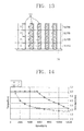
- a torque of the electromotor 140 maintains a relatively high level with no big change at a relatively low number of rotations (frequency), but the torque is drastically reduced above approximately 6000 rpm as illustrated with a first curve (L1).
- each segment conductor 170 is gradually reduced as increasing the number or rotations (frequency) of the electromotor 140 as illustrated with a second curve (L2).
- the number of turns for each pole may be increased to reduce a cross-sectional area of each segment conductor 170 and suppress an increase of resistance caused by the skin effect, thereby enhancing the efficiency.
- the number of rotations may be increased by increasing the number of turns for each pole and connecting them in parallel with one another. Due to this, it may be possible to enhance the output.
- the number of rotations may be increased, thereby reducing the size of the electromotor (stator 150 and rotor 190) to the extent.
- stator winding 161 may be configured such that the conductors or coils (in effect, insertion portions 172a of the first conductor 171 and/or insertion portions 176a of the second conductor 175, hereinafter, abbreviated as "insertion portions") having the same phase (u-phase 162a, v-phase 162b, w-phase 162c) and having the same current direction are distributed over four slots as illustrated in FIGS. 10A through 10C and 11 .
- insertion portions the conductors or coils (in effect, insertion portions 172a of the first conductor 171 and/or insertion portions 176a of the second conductor 175, hereinafter, abbreviated as "insertion portions" having the same phase (u-phase 162a, v-phase 162b, w-phase 162c) and having the same current direction are distributed over four slots as illustrated in FIGS. 10A through 10C and 11 .
- insertion portions the conductors or coils (in effect, insertion portions 172a of the
- the u-phase 162a in case of the u-phase 162a as an example, it may be disposed with six insertion portions inserted into a first layer and a second layer of the 12nd to 14th slots and six insertion portions inserted into a third layer and a fourth layer of the 13th to 15th slots.
- the six insertion portions inserted into a first layer and a second layer of the 12nd to 14th slots may constitute one pole of the first winding portion 163, and the six insertion portions inserted into a third layer and a fourth layer of the 13th to 15th slots may constitute one pole of the second winding portion 164.
- the one pole of the first winding portion 163 and the one pole of the second winding portion 164 may be disposed to be separated from each other by one slot pitch along the circumferential direction.
- the stator winding 161 may be configured such that the insertion portions having the same phase as well as having the same current direction are disposed at five slots as illustrated in FIG. 12 . Due to this, it may be possible to reduce the torque ripple and reduce the vibration and noise.
- the one pole of the first winding portion 163 and the one pole of the second winding portion 164 may be disposed to be separated from each other by two slot pitches along the circumferential direction.
- the one pole of the second winding portion 164 in which three insertion portions are inserted into the third layer and the fourth layer, respectively may be disposed with an interval of two slot pitches to one another, compared to the one pole of the first winding portion 163 in which three insertion portions are sequentially disposed at the first layer and the second layer, respectively, as illustrated in FIG. 12 .
- stator winding 161 may be configured such that the insertion portions having the same phase as well as having the same current direction are disposed at three slots as illustrated in FIG. 13 . Due to such a configuration, it may be possible to increase the torque ripple and increase the vibration and noise compared to the foregoing configuration in connection with FIGS. 11 and 12 . However, it may be possible to increase the number of segment conductors 170 and reduce a cross-sectional area of each of the segment conductors 170 compared to the related art, thereby enhancing the efficiency. Furthermore, the increased number of segment conductors 170 may be divided into a suitably number and connected in parallel with each other to increase the rotation speed, thereby allowing rotation at high speed.
- the segment conductor 170 may have a rectangular cross section, and at least one edge of the cross section of the segment conductor 170 may be configured with above 1.7 mm. Due to this, it may be possible to enhance the operation efficiency.
- the segment conductor 170 may be configured to have a rectangular shaped cross section with a smaller edge size of 1.7 mm.
- stator winding 161 according to the present embodiment will be described by taking a case where the insertion portions having the same phase as well as having the same current direction are disposed at four slots as an example as illustrated in FIGS. 3 and 10A through 10C .
- the segment conductors 170 may be inserted into each slot 155 of the stator core 151, respectively.
- Four insertion portions may be inserted into each slot 155, respectively, to be separated from one another along the radial direction.
- Each phase of the stator winding 161 may have the first winding portion 163 and second winding portion 164 connected in parallel with each other, and the first winding portion 163 and second winding portion 164 for each phase may be configured to have a first coil portion 165a and a second coil portion 165b connected in series with each other.
- an end portion of the first coil portion 165a of the first winding portion 163 in the u-phase 162a may be disposed at layer 2 of the 23rd slot such that a lower end thereof is connected to a lead wire 181 a of the u-phase 162a, and the other end portion of the first coil portion 165a may be disposed at layer 3 of the 25th slot.
- An end portion of the second coil portion 165b of the first winding portion 163 in the u-phase 162a may be disposed at layer 2 of the 21 st slot such that a lower end thereof is connected to the first coil portion 165a by means of the connection conductor 177, and the other end portion of the second coil portion 165b may be disposed at layer 2 of the 32nd slot such that a lower end thereof is connected to the neutral line 185.
- An end portion of the first coil portion 165a of the second winding portion 164 in the u-phase 162a may be disposed at layer 4 of the 24th slot and a lower end thereof may be connected to a lead wire 180 of the u-phase 162a.
- the other end portion of the first coil portion 165a may be disposed at layer 3 of the 13th slot.
- An end portion of the second coil portion 165b of the second winding portion 164 in the u-phase 162a may be disposed at layer 3 of the 22nd slot and a lower end portion thereof may be connected to the first coil portion 165a of the second winding portion 164 by means of the connection conductor 177.
- the other end portion of the second coil portion 165b of the second winding portion 164 may be disposed at layer 4 of the 33rd slot and a lower end portion thereof may be connected to the neutral line 185.
- An end portion of the first coil portion 165a of the first winding portion 163 in the v-phase 162b may be disposed at layer 2 of the 35th slot such that a lower end thereof is connected to a lead wire 180 of the v-phase 162b.
- the other end portion of the first coil portion 165a may be disposed at layer 1 of the 24th slot.
- An end portion of the second coil portion 165b of the first winding portion 163 in the v-phase 162b may be disposed at layer 1 of the 33rd slot and a lower end thereof may be connected to the first coil portion 165a by means of the connection conductor 177.
- the other end portion of the second coil portion 165b may be disposed at layer 4 of the 44th slot and a lower end thereof may be connected to the neutral line 185.
- An end portion of the first coil portion 165a of the second winding portion 164 in the v-phase 162b may be disposed at layer 4 of the 36th slot and a lower end thereof may be connected to a lead wire 181 b of the v-phase 162b.
- the other end portion of the first coil portion 165a may be disposed at layer 3 of the 25th slot.
- An end portion of the second coil portion 165b of the second winding portion 164 in the v-phase 162b may be disposed at layer 3 of the 34th slot and a lower end portion thereof may be connected to the first coil portion 165a by means of the connection conductor 177.
- the other end portion of the second coil portions 165b may be disposed at layer 4 of the 45th slot and a lower end portion thereof may be connected to the neutral line 185.
- An end portion of the first coil portion 165a of the first winding portion 163 in the w-phase 162c may be disposed at layer 2 of the 29th slot and a lower end thereof may be connected to a lead wire 181 c of the w-phase 162c.
- the other end portion of the first coil portion 165a may be disposed at layer 1 of the 18th slot.
- An end portion of the second coil portion 165b of the first winding portion 163 in the w-phase 162c may be disposed at layer 1 of the 27th slot and a lower end thereof may be connected to the first coil portion 165a by means of the connection conductor 177.
- the other end portion of the second coil portion 165b may be disposed at layer 2 of the 38th slot and a lower end thereof may be connected to the neutral line 185.
- An end portion of the first coil portion 165a of the second winding portion 164 in the w-phase 162c may be disposed at layer 4 of the 30th slot and a lower end thereof may be connected to a lead wire 181 c of the w-phase 162c.
- the other end portion of the first coil portion 165a may be disposed at layer 1 of the 18th slot.
- An end portion of the second coil portion 165b of the second winding portion 164 in the w-phase 162c may be disposed at layer 3 of the 28th slot and a lower end portion thereof may be connected to the first coil portion 165a by means of the connection conductor 177.
- the other end portion of the second coil portion 165b may be disposed at layer 4 of the 39th slot and a lower end portion thereof may be connected to the neutral line 185.
- the lead wires 181a, 181b, 181c may be connected to the inverter device 130, respectively. Due to this, a driving power source converted from the inverter device 130 may be provided to each phase.
- the inverter device 130 may convert a direct current power source provided from the battery 125 into a driving power source at a predetermined frequency (for example, 800 Hz) to provide it to the electromotor 140.
- a predetermined frequency for example, 800 Hz
- stator winding 161 When a driving power source provided from the inverter device 130 is applied to the stator winding 161, the stator winding 161 may form a rotational magnetic field. Due to this, the rotor 190 may be rotated around the rotation shaft 197 by an interaction between the magnet 195 and the rotational magnetic field.
- the rotational force of the rotor 190 may be decelerated to a predetermined deceleration ratio (for example, 8.5:1) through the decelerator 135 connected to the rotation shaft 197 and transferred to the wheel 115.
- a predetermined deceleration ratio for example, 8.5:1
Landscapes
- Engineering & Computer Science (AREA)
- Power Engineering (AREA)
- Transportation (AREA)
- Mechanical Engineering (AREA)
- Life Sciences & Earth Sciences (AREA)
- Sustainable Development (AREA)
- Sustainable Energy (AREA)
- Windings For Motors And Generators (AREA)
Abstract
Description
- The present invention relates to a stator of an electric machine, an electromotor having the same, and an electric vehicle having the electromotor, and more particularly, to a stator of an electric machine, an electromotor having the same, and an electric vehicle having the electromotor capable of increasing the number of rotations and reducing the size thereof.
- As is generally known, an electric generator such as an alternator and/or a generator, and an electromotor (hereinafter, referred to as an "electric machine") such as a motor and/or a linear motor may be configured with a stator and a mover configured to relatively move with respect to the stator.
- The stator of the electric machine may be configured with a stator core having a plurality of slots, and stator windings wound around the slots.
- The stator windings may be typically configured by a method of winding a wire (stranded wire) having a relatively thin diameter around an internal portion of the slot a multiple number of times and a method of winding a wire around the tooth (pole) in a concentrated manner.
- However, according to such as a stator winding method in the related art, the operation efficiency thereof may be reduced because a ratio of an occupied area (cross-sectional area) of the conductor (coil) with respect to a cross-sectional area of the slot is relatively small. Furthermore, there is a limit in increasing a cross-sectional area ratio of the conductor with a conventional stator winding method using a wire having such a thin diameter, thereby having a limit in the enhancement of the output density and efficiency.
- On the other hand, according to an electromotor for electric vehicles particularly requiring a high output density and high efficiency, it may be very important to increase a ratio of a cross-sectional area of the conductor with respect to the slot.
- Taking such problems into consideration, there has been known a method of inserting a rectangular copper wire having a relatively large width (diameter) into a slot to form a stator winding (for example,
U.S. Patent Laid-Open Publication No. 2003-438429, May 15, 2003 ). - However, according to such a conventional stator winding method using a rectangular copper wire, there is a problem in which the size of the stator and rotor in an electromotor should be increased to enhance the output of the electromotor.
- Meanwhile, according to such a conventional stator winding method using a rectangular copper wire, it is not easy to control the number of turns, thus resulting in a limit on the high-speed operation (for example, above 7000 rpm (revolution per minute).
- Accordingly, an object of the present disclosure is to provide a stator of an electric machine, an electromotor having the same, and an electric vehicle having the electromotor capable of increasing the number of rotations.
- Furthermore, another object of the present disclosure is to provide a stator of an electric machine, an electromotor having the same, and an electric vehicle having the electromotor capable of reducing the external size thereof while maintaining the same output.
- In order to accomplish the foregoing object of the present disclosure, there is provided a stator of an electric machine including a stator core having a plurality of slots; and a stator winding in which a winding having a rectangular shaped cross section or circular shaped cross section is wound in series around the slot, wherein the stator winding has a plurality of winding portions connected in parallel with one another for each phase, and each of the winding portions has a plurality of segment conductors inserted into three or more slots for each pole.
- Here, each of the segment conductors may be configured to have a rectangular cross section.
- The segment conductor may be configured to have a first layer through a fourth layer separated from one another in a radial direction within the each slot.
- Each of the segment conductors may include a first conductor having a pair of insertion portions inserted into different slots from each other, and a connection portion connecting the insertion portions to each other, and extension portions extended from the insertion portions, respectively; and a second conductor having an insertion portion inserted into the slot, and a plurality of extension portions extended from both end portions of the insertion portion, respectively.
- The stator winding may be configured to have a plurality of lead wires connecting each phase power to a winding portion.
- The stator winding may be configured to have a first winding portion and a second winding portion connected to in parallel with each other, and each lead wire may have a power connecting portion connected to a power source, and a first branch portion and a second branch portion branched from the power connecting portion and connected to each of one ends of the first winding portion and the second winding portion, respectively.
- The stator winding may be configured to have a neutral line (or a neutral conductor) connecting each of the other ends of the first winding portion and the second winding portion.
- The neutral line may be configured to have a first branch portion through a sixth branch portion connected to each phase of the first winding portion and the second winding portion.
- The first winding portion and the second winding portion may be disposed such that the poles of the same phase are separated from one another by one slot or two slots in a circumferential direction of the stator core.
- On the other hand, according to another field of the present disclosure, there is provided a stator of an electric machine including a stator core having a plurality of slots; and a stator winding in which a winding having a rectangular shaped cross section or circular shaped cross section is wound in series around the slot, wherein the stator winding has a plurality of winding portions connected in parallel with one another for each phase, and each of the winding portions has a plurality of poles, and each of the winding portions has a first layer through a fourth layer, and has a plurality of segment conductors inserted into the slot such that the number of slots is three or more for each pole and each phase, and when one of the plurality of poles is disposed at four slots, a first layer and a second layer of the first slot among the four slots have the same phase along a circumferential direction of the stator core, and a third layer and a fourth layer thereof have the same phase, and the second layer and the third layer thereof have different phases.
- Here, a first layer through a fourth layer of the second slot and the third slot among the four slots of the one pole may be configured to have the same phase.
- On the other hand, according to still another field of the present disclosure, there is provided a stator of an electric machine including a stator core having a plurality of slots; and a stator winding in which a winding having a rectangular shaped cross section or circular shaped cross section is wound in series around the slot, wherein the stator winding has a plurality of winding portions connected in parallel with one another for each phase, and each of the winding portions has a plurality of poles, and each of the winding portions has a first layer through a fourth layer, and has a plurality of segment conductors inserted into the slot such that the number of slots is three or more for each pole and phase, and when one of the poles is disposed at five slots, a first layer and a second layer of the first, second, fourth and fifth slots among the five slots of the one pole have the same phase along a circumferential direction of the stator core, and a third layer and a fourth layer thereof have the same phase, and the second layer and the third layer thereof have different phases.
- Here, a first layer through a fourth layer of the third slot among the five slots of the one pole may be configured to have the same phase.
- Furthermore, according to yet still another field of the present disclosure, there is provided a stator of an electric machine, including a stator core having a plurality of slots; and a stator winding in which a winding having a rectangular shaped cross section or circular shaped cross section is wound in series around the slot, wherein the stator winding has a plurality of winding portions connected in parallel with one another for each phase, and each of the winding portions has a plurality of poles, and each of the winding portions has a first layer through a fourth layer, and has a plurality of segment conductors inserted into the slot such that the number of slots is three or more for each pole and phase, and when one of the plurality of poles is disposed at three slots, a first layer through a fourth layer of the three slots of the one pole all have the same phase.
- Furthermore, according to still yet another field of the present disclosure, there is provided an electromotor including a stator of the electric machine; and a rotor rotatably disposed with respect to the stator, wherein the stator and rotator are configured to rotate at 12000 through 24000 rpm.
- Here, the stator may be configured to have 8 poles and 72 slots.
- On the other hand, according to yet still another field of the present disclosure, there is provided an electric vehicle including a vehicle body; a battery provided in the vehicle body; and the electromotor provided in the vehicle body to provide a driving force to the vehicle body.
- Here, the electric vehicle may further include an inverter provided in the vehicle body and connected to the battery and the electromotor to provide the driving power of the electromotor.
- The inverter may be configured to provide alternating current power at frequencies of 500 to 1000 Hz to the electromotor.
- The vehicle body may be configured to have a plurality of wheels, and may further include a decelerator provided between the electromotor and the wheel, wherein the decelerator has a deceleration ratio of 5.5:1 to 10:1.
- On the other hand, according to still yet another field of the present disclosure, there is provided an electromotor including a stator having a stator core having a plurality of slots and a stator winding in which a winding having a rectangular shaped cross section or circular shaped cross section is wound in series around the slot; and a rotator rotatably disposed with respect to the stator, wherein the stator core has 36 through 72 slots, and the stator winding has a plurality of winding portions connected in parallel with one another with the number of 2 to 8 in parallel for each phase, and the stator winding has 3 to 10 poles, and alternating current power of 500 to 1000 Hz is applied to the stator winding, and the rotor is rotatably configured at 10000 to 24000 rpm.
- On the other hand, according to yet still another field of the present disclosure, there is provided an electric vehicle including a vehicle body; a battery provided in the vehicle body; and the electromotor provided in the vehicle body to provide a driving force to the vehicle body.
- Here, the electric vehicle may further include a decelerator having a deceleration ratio of 5.5:1 to 10:1.
- As described above, according to an embodiment of the present disclosure, a stator winding may have a plurality of winding portions connected in parallel for each phase, and each of the winding portions may have a segment conductor disposed at three or more slots to increase the number of rotations, thereby enhancing the output of the electromotor.
- Furthermore, it may be possible to reduce a cross sectional area of each segment conductor, thereby suppressing an increase of the alternating current resistance by a skin effect as well as enhancing the efficiency.
- Furthermore, when the same output is maintained, it may be possible to reduce a size of the electromotor, namely, stator and rotor.
- Furthermore, a lead wire and/or a neutral line connected to a plurality of winding portions at the same time may be provided therein to expedite and facilitate a stator winding and connecting work.
-
-
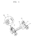
FIG. 1 is a schematic configuration diagram illustrating an electric vehicle according to an embodiment of the present disclosure; -
FIG. 2 is a cross-sectional view illustrating an electromotor inFIG. 1 ; -
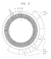
FIG. 3 is a schematic configuration diagram illustrating a stator of the electromotor inFIG. 2 ; -
FIG. 4 is a view illustrating a lead wire inFIG. 3 ; -
FIG. 5 is a view illustrating a neutral line inFIG. 3 ; -
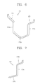
FIG. 6 is a view illustrating a first conductor of the segment conductor inFIG. 2 ; -
FIG. 7 is a view illustrating a second conductor of the segment conductor inFIG. 2 ; -
FIG. 8 is a view schematically illustrating the connection configuration of a stator winding of the electromotor inFIG. 2 ; -
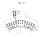
FIG. 9 is a partially enlarged view ofFIG. 3 ; -
FIGS. 10A through 10C are connection diagrams illustrating a stator winding inFIG. 2 ; -
FIGS. 11 through 13 are views for explaining the arrangement of a segment conductor inFIG. 3 ; and -
FIG. 14 is a view illustrating a relation among a number of rotations and a torque of the stator winding and a cross sectional area of the segment conductor inFIG. 2 . - Hereinafter, an embodiment of the present disclosure will be described in detail with reference to the accompanying drawings.
- As illustrated in
FIG. 1 , an electric vehicle having an electromotor according to an embodiment of the present disclosure may include avehicle body 110, abattery 125 provided in thevehicle body 110, and anelectromotor 140 provided in thevehicle body 110 to provide a driving force to thevehicle body 110. - A passenger space (not shown) may be provided in an upper region of the
vehicle body 110. - A plurality of
wheels 115 may be provided in thevehicle body 110 to enable driving. - The
wheels 115 may be disposed at both sides of the front and rear regions, respectively, of thevehicle body 110. - A
suspension device 120 may be provided between thevehicle body 110 and thewheels 115 to absorb vibrations and shocks generated while driving. - A
battery 125 may be provided in thevehicle body 110 to supply power. - The
battery 125 may be configured with a secondary battery to allow charging. - On the other hand, an
electromotor 140 may be provided in thevehicle body 110 to provide a driving force to thevehicle body 110, more particularly, to thewheels 115. - A deceleration device or
decelerator 135 may be provided at one side of the electromotor 140 (more particularly, at the output side) to transfer a rotational force of theelectromotor 140 to thewheels 115 with a predetermined deceleration ratio. - The
decelerator 135 may be configured to have a deceleration ratio of 5.5:1 to 10:1. - The
decelerator 135 may preferably have a deceleration ratio, for example, 8.5:1. - An
inverter device 130 connected to thebattery 125 and theelectromotor 140 may be provided in thevehicle body 110. - The
inverter device 130 may be configured to convert a direct current power source provided from thebattery 125 into a driving power source suitable for driving theelectromotor 140 and provide it to theelectromotor 140. - The
inverter device 130 may be configured to provide alternating current power having a range of frequencies of 500 to 1000 Hz, for example, to theelectromotor 140. - The
inverter device 130 may be configured to provide alternating current power of 800 Hz to theelectromotor 140 as a driving power source. - As illustrated in
FIG. 2 , theelectromotor 140 may include astator 150, and arotor 190 rotatably disposed with respect to thestator 150, and thestator 150 androtor 190 may be rotatably configured at 12000 to 24000 rpm. - The
electromotor 140 may have anenclosure 141 for forming an accommodation space therein. - The
enclosure 141 may be configured in a cylindrical shape, for example. - More specifically, the
enclosure 141 may be configured to have a cylindrical shape having both open sides. - A cover or bracket 145 (hereinafter, referred to as a "
bracket 145") may be configured at both end portions of theenclosure 141. - The
bracket 145 may be combined with both end portions of theenclosure 141 in a separable manner. - A bearing 147 for rotatably supporting the
rotor 190 may be provided in thebracket 145. - The
rotor 190 may be configured to have arotor core 191 and amagnet 195 provided in therotor core 191. - A
rotation shaft 197 may be provided in therotor core 191. Ashaft hole 193 into which therotation shaft 197 is inserted may be formed to penetrate therotor core 191. Both sides of therotation shaft 197 may be rotatably supported by thebearing 147. - A
magnet insertion portion 194 may be provided in therotor core 191 into which themagnet 195 can be inserted along the axial direction. - According to the present embodiment, it is illustrated a case where the
rotor 190 is configured with a so-called interior permanent magnet (IPM)type rotor 190 having a plurality ofmagnets 195 inserted into therotor core 191 in the axial direction, but therotor 190 may be also configured with a so-called surface permanent magnet (SPM) type rotor (not shown) in which a magnet (not shown) is provided at an outer surface of therotor core 191. Furthermore, it may be configured with a so-called induction rotor type rotor (not shown) having therotor core 191, a plurality of conductor bars and an end ring. - The
magnet 195 may be configured in a rectangular plate shape, for example. - The
magnets 195 may be separated from one another with the same intervals along a circumferential direction of therotor core 191. It may be configured with eightmagnets 195, and different magnetic poles (N and S poles) may be alternately disposed along a circumferential direction of therotor core 191. - On the other hand, the
stator 150 may include astator core 151 having a plurality ofslots 155, and a stator winding 161 wound around theslot 155, and the stator winding 161 may have a plurality of windingportions portions segment conductor 170 inserted into three ormore slots 155 for each pole. - An
accommodation space 153 in which therotor 190 is rotatably accommodated may be formed in thestator core 151. - The
stator core 151 may be formed of a plurality ofelectrical steel sheets 152 using an insulating layer method. - The
electrical steel sheets 152 may have a circular disk (plate) shape formed with theaccommodation space 153 - The
stator core 151 may have a plurality ofslots 155 andteeth 156 formed around theaccommodation space 153. - The
slots 155 andteeth 156 may be alternately disposed with one another along a circumferential direction of thestator core 151. - The
slots 155 may be configured to have a long length in the radial direction. - The stator winding 161 may have a plurality of winding
portions - For example, the stator winding 161 may be configured to have a first winding
portion 163 and a second windingportion 164 for each phase (u-phase 162a, v-phase 162b, w-phase 162c) as illustrated inFIGS. 3 and8 . - According to the present embodiment, it is illustrated a case where the stator winding 161 is configured in two parallel winding portions to have the first winding
portion 163 and the second windingportion 164 connected in parallel with one another, but may be also configured with four or eight winding portions in parallel. - The stator winding 161 may have lead wires or lead wires 180 (hereinafter, referred to as "lead
wires 180"), respectively, connecting the first windingportion 163 and second windingportion 164 to theinverter device 130 for each phase to apply a driving power source to each phase. - It may be configured with three
lead wires 180. More specifically, thelead wires controller 180 may have au-phase lead wire 181a, a v-phase lead wire 181 b, and a w-phase lead wire 181 c. - The
lead wire 180, for example,u-phase lead wire 181a, may be configured to have aninverter connection portion 182 connected to theinverter device 130, and afirst branch portion 183 and asecond branch portion 184 branched from theinverter connection portion 182 and connected to the first windingportion 163 and the second windingportion 164, respectively, as illustrated inFIG. 4 . - The
lead wire 180 may be configured with a rectangular copper wire having a rectangular cross section, for example. - The stator winding 161 may have a
neutral wire 185 or neutral line 185 (hereinafter, referred to as a "neutral line 185") connecting each of the ends of the first windingportion 163 and second windingportion 164 for each phase. Theneutral line 185 may be configured in the form of a line to connect the windingportions - The
neutral line 185 may have abranch portion 187 branched to connect each of the ends of the first windingportion 163 and second windingportion 164 for each phase, and aconnection portion 186 connecting thebranch portion 187, for example, as illustrated inFIG. 5 . Thebranch portion 187 may have afirst branch portion 188a through asixth branch portion 188f connected to each of the windingportions neutral line 185 may be disposed along a circumferential direction of thestator core 151. InFIG. 5 , it is illustrated a case where each of thebranch portion 187 andconnection portion 186 is configured in a linear shape, but theconnection portion 186 may be properly curved to correspond to a circumference of thestator core 151. Furthermore, an interval between the eachbranch portion 187 and a length of thebranch portion 187 may be properly controlled. - On the other hand, the stator winding 161 may have a plurality of poles, and the first winding
portion 163 and second windingportion 164 for each phase may be configured to have asegment conductor 170 inserted into theslot 155 such that the number of slots is equal to or greater than three for each pole and phase. For example, the first windingportion 163 and second windingportion 164 may be configured such that at least twelvesegment conductors 170 are inserted to three to five slots, respectively, during the insertion of foursegment conductors 170 for each slot. - The stator winding 161 may be configured to have four poles, six poles or eight poles, for example.
- The
stator 150 may be configured to have threeslots 155 or fourslots 155 for each phase (for example, u-phase 162a, v-phase 162b, w-phase 162c) per one pole. - More specifically, on the assumption that the
stator 150 is configured with thestator core 151 with an outer diameter of 200 to 300 mm, the number of rotations of therotor 190 with 10000 to 24000 rpm, and thedecelerator 135 with a deceleration ratio of 5.5:1 to 10:1, and theinverter device 130 with a frequency control section of 500 to 1000 Hz, thestator 150 may be configured with the stator winding 161 with 4 poles, thestator core 151 with 36 slots, and three slots for each pole and each phase, and any one of two, four and eightstator windings 161 in parallel. - Furthermore, the
stator 150 may be configured with the stator winding 161 with 4 poles, thestator core 151 with 48 slots, and either one of two or fourstator windings 161 in parallel when there are four slots for each pole and phase. - Furthermore, the
stator 150 may have the stator winding 161 with 6 poles, thestator core 151 with 54 slots, and twostator windings 161 in parallel when there are three slots for each pole and each pole. - Furthermore, the
stator 150 may be configured with the stator winding 161 with 6 poles, thestator core 151 with 72 slots, and either one of two or fourstator windings 161 in parallel when there are four slots for each pole and each phase. - Furthermore, the
stator 150 may be configured with the stator winding 161 with 8 poles, thestator core 151 with 72 slots, and twostator windings 161 in parallel when there are three slots for each pole and each phase. - Hereinafter, a case where the
electromotor 140 according to the present embodiment is configured with the stator winding 161 with 8 poles, three slots for each pole and each phase, thestator core 151 with total 72 slots, and twostator windings 161 in parallel will be described as an example. Furthermore, theelectromotor 140 according to the present embodiment may be configured such that a driving power source (alternating current power) at a frequency of 800 Hz is received from theinverter device 130, and therotor 190 is rotated at 12000 rpm. - A plurality of
segment conductors 170 may be inserted into eachslot 155 of thestator core 151. Thesegment conductors 170 within theslot 155 may be separated from one another in the radial direction. - For example, as illustrated in
FIG. 9 , foursegment conductors 170 may be inserted into the eachslot 155 to be separated in the radial direction. Here, foursegment conductors 170 disposed in the radial direction within eachslot 155 of thestator core 151 may be disposed on the same circumference from the inside to the outside along the radial direction to form a first layer through a fourth layer. Hereinafter, thesegment conductor 170 disposed closest to the side of theaccommodation space 153 may be referred to as a first layer, and thesegment conductor 170 disposed closest to the circumference of thestator core 151 may be referred to as a fourth layer. A second layer and a third layer may be disposed, respectively, between the first layer and the fourth layer. - An insulating
member 178 may be provided between each of thesegment conductors 170 and thestator core 151 to provide insulation therebetween. - On the other hand, the
segment conductor 170 may be inserted at one side of thestator core 151 and protruded from the other side thereof along the axial direction, for example. - For example, the
segment conductor 170 may be configured with afirst conductor 171 having a pair ofinsertion portions 172a inserted intodifferent slots 155 from each other, and aconnection portion 172b connecting theinsertion portions 172a to each other, andextension portions 173 extended from theinsertion portions 172a, respectively, as illustrated inFIG. 6 . - The
first conductor 171 may be configured such that an interval between the twoinsertion portions 172a is 9 slot pitches. For example, thefirst conductor 171 may be configured such that when theinsertion portion 172a at the one side thereof is inserted intoslot 1, theinsertion portion 172a at the other side thereof is inserted intoslot 10 which is a ninth slot along a circumferential direction of thestator core 151 toward the one side as illustrated inFIGS. 10A through 10C . - Here, the two
insertion portions 172a of thefirst conductor 171 may be inserted intodifferent slots 155 to be disposed at different layers. For example, theinsertion portion 172a at one side of thefirst conductor 171 may be inserted intolayer 3 of the first slot and theinsertion portion 172a at the other side thereof may be inserted intolayer 4 of the tenth slot. - The
first conductor 171 may be twisted by approximately 180 degrees at theconnection portion 172b such that the inner and outer surfaces of the twoinsertion portions 172a are disposed in an opposite direction to each other. - The each
extension portion 173 may be inclined and extended in the upward direction toward the outside thereof at an end portion of the eachinsertion portion 172a. The eachextension portion 173 may be brought into contact with theother extension portion 173 in a conductive manner. An end portion of theextension portion 173 may be connected in a conductive manner by a welding, for example. Here, an end portion of the eachextension portion 173 may be bent to be disposed along the top/down direction. Due to this, lateral surfaces of twoextension portions 173 to be welded to each other may be easily brought into contact with each other, thereby facilitating a welding work. - More specifically, the
extension portion 173 extended in the upward direction from theinsertion portion 172a inserted intolayer 3 of the first slot may be brought into contact with theextension portion 173 extended in the upward direction fromlayer 4 of the 64th slot with each other in a conductive manner. An end portion of theextension portion 173 of thefirst conductor 171 inserted into the first slot and an end portion of theextension portion 173 of thefirst conductor 171 inserted into the 64th slot may be disposed with awelding portion 179 at which lateral surfaces thereof are welded in a state of being brought into contact with each other in a conductive manner approximately at an upper side of the 68th slot and 69th slot. - On the other hand, part of the
first conductor 171 may be configured such that an interval between the twoinsertion portions 172a is 8 slot pitches. - More specifically, it may be configured such that the
insertion portion 172a at one side thereof is inserted intoslot 14 and theinsertion portion 172a at the other side thereof is inserted intoslot 22 which is the eighth slot thereafter as illustrated inFIG. 10A . - The
segment conductor 170 may be configured to have asecond conductor 175 having aninsertion portion 176a inserted into theslot 155, and a plurality ofextension portions 176b extended from both end portions of theinsertion portion 176a, respectively, as illustrated inFIG. 7 . - The
second conductor 175 may be configured with an approximately half shape of thefirst conductor 171 from which a central portion of thefirst conductor 171 is cut. - For example, an end portion of the
second conductor 175 may be connected to theneutral line 185 or thelead wire 180. - As illustrated in
FIG. 10A , alead wire 181a of the u-phase 162a may be connected to an end portion of theextension portion 176b at a lower side of thesecond conductor 175 inserted intolayer 4 of the 24th slot on the drawing. - Furthermore, a
neutral line 185 may be connected to an end portion of theextension portion 176b at a lower side of thesecond conductor 175 inserted intolayer 4 of the 33rd slot. - Furthermore, an end of the
connection conductor 177 may be connected to an end portion of theextension portion 176b at a lower side of thesecond conductor 175 inserted intolayer 3 of the 13th slot, and the other end thereof may be connected to an end portion of theextension portion 176b at a lower side of thesecond conductor 175 inserted intolayer 3 of the 22nd slot. Here, theconnection conductor 177 may be configured with a copper wire having a rectangular cross section. The length of theconnection conductor 177 may be properly controlled. - On the other hand, the stator winding 161 may include a first winding
portion 163 and a second windingportion 164 for each phase as illustrated inFIGS. 10A through 10C . - For example, the first winding
portion 163 for each phase may be configured by connectingsegment conductors 170 forming a first layer and a second layer. The first windingportion 163 may be configured by connecting thesegment conductors 170 disposed on the first layer and the second layer in series with each other. - Furthermore, the second winding
portion 164 for each phase may be configured by connectingsegment conductors 170 forming a third layer and a fourth layer. The second windingportion 164 may be configured by connecting thesegment conductors 170 disposed on the third layer and the fourth layer in series with each other. Here, the first windingportion 163 for each phase may be also configured by connecting a first layer with a third layer, and the second windingportion 164 may be also configured by connecting a second layer with a fourth layer. - For the each stator winding 161, the first winding
portion 163 and second windingportion 164 for each phase may be configured with eight poles, and six turns for each pole. In other words, the first windingportion 163 and second windingportion 164 may be configured to have six insertion portions for each pole (insertion portions 172a of thefirst conductor 171 and/orinsertion portions 176b of the second conductor 175). - On the other hand, the stator winding 161 may be configured such that one pole for each phase (u-phase 162a, v-phase 162b, w-phase 162c) is distributed over three slots. Due to this, it may be possible to reduce a cross-sectional area of the
segment conductor 170 inserted into eachslot 155. - When an alternating current power source with frequencies above a predetermined frequency is applied to each
segment conductor 170, the resistance (effective resistance) at a central portion of eachsegment conductor 170 may be drastically increased due to a so-called skin effect. Due to this, the efficiency may be drastically reduced. - Referring to
FIG. 14 , it is seen that a torque of theelectromotor 140 maintains a relatively high level with no big change at a relatively low number of rotations (frequency), but the torque is drastically reduced above approximately 6000 rpm as illustrated with a first curve (L1). - Furthermore, it is seen that a skin depth of each
segment conductor 170 is gradually reduced as increasing the number or rotations (frequency) of theelectromotor 140 as illustrated with a second curve (L2). - According to an embodiment of the present disclosure, the number of turns for each pole may be increased to reduce a cross-sectional area of each
segment conductor 170 and suppress an increase of resistance caused by the skin effect, thereby enhancing the efficiency. - Furthermore, the number of rotations may be increased by increasing the number of turns for each pole and connecting them in parallel with one another. Due to this, it may be possible to enhance the output.
- Furthermore, when the same output is maintained, the number of rotations may be increased, thereby reducing the size of the electromotor (
stator 150 and rotor 190) to the extent. - More specifically, the stator winding 161 may be configured such that the conductors or coils (in effect,
insertion portions 172a of thefirst conductor 171 and/orinsertion portions 176a of thesecond conductor 175, hereinafter, abbreviated as "insertion portions") having the same phase (u-phase 162a, v-phase 162b, w-phase 162c) and having the same current direction are distributed over four slots as illustrated inFIGS. 10A through 10C and11 . As a result, it may be possible to reduce the torque ripple and reduce the vibration and noise. Due to this, it may be possible to implement and/or provide an electromotor configured with a relatively small size and rotated at high speed while maintaining the same output with a lower vibration and noise. - As illustrated in
FIG. 11 , in case of the u-phase 162a as an example, it may be disposed with six insertion portions inserted into a first layer and a second layer of the 12nd to 14th slots and six insertion portions inserted into a third layer and a fourth layer of the 13th to 15th slots. - Here, the six insertion portions inserted into a first layer and a second layer of the 12nd to 14th slots may constitute one pole of the first winding
portion 163, and the six insertion portions inserted into a third layer and a fourth layer of the 13th to 15th slots may constitute one pole of the second windingportion 164. The one pole of the first windingportion 163 and the one pole of the second windingportion 164 may be disposed to be separated from each other by one slot pitch along the circumferential direction. - The stator winding 161 may be configured such that the insertion portions having the same phase as well as having the same current direction are disposed at five slots as illustrated in
FIG. 12 . Due to this, it may be possible to reduce the torque ripple and reduce the vibration and noise. - More specifically, the one pole of the first winding
portion 163 and the one pole of the second windingportion 164 may be disposed to be separated from each other by two slot pitches along the circumferential direction. For example, the one pole of the second windingportion 164 in which three insertion portions are inserted into the third layer and the fourth layer, respectively, may be disposed with an interval of two slot pitches to one another, compared to the one pole of the first windingportion 163 in which three insertion portions are sequentially disposed at the first layer and the second layer, respectively, as illustrated inFIG. 12 . - Furthermore, the stator winding 161 may be configured such that the insertion portions having the same phase as well as having the same current direction are disposed at three slots as illustrated in
FIG. 13 . Due to such a configuration, it may be possible to increase the torque ripple and increase the vibration and noise compared to the foregoing configuration in connection withFIGS. 11 and 12 . However, it may be possible to increase the number ofsegment conductors 170 and reduce a cross-sectional area of each of thesegment conductors 170 compared to the related art, thereby enhancing the efficiency. Furthermore, the increased number ofsegment conductors 170 may be divided into a suitably number and connected in parallel with each other to increase the rotation speed, thereby allowing rotation at high speed. - The
segment conductor 170 according to the present embodiment may have a rectangular cross section, and at least one edge of the cross section of thesegment conductor 170 may be configured with above 1.7 mm. Due to this, it may be possible to enhance the operation efficiency. For example, thesegment conductor 170 may be configured to have a rectangular shaped cross section with a smaller edge size of 1.7 mm. - Hereinafter, the stator winding 161 according to the present embodiment will be described by taking a case where the insertion portions having the same phase as well as having the same current direction are disposed at four slots as an example as illustrated in
FIGS. 3 and10A through 10C . - The segment conductors 170 (
first conductor 171 and/or second conductor 175) may be inserted into eachslot 155 of thestator core 151, respectively. Four insertion portions may be inserted into eachslot 155, respectively, to be separated from one another along the radial direction. - Each phase of the stator winding 161 may have the first winding
portion 163 and second windingportion 164 connected in parallel with each other, and the first windingportion 163 and second windingportion 164 for each phase may be configured to have afirst coil portion 165a and asecond coil portion 165b connected in series with each other. - More specifically, referring to
FIGS. 3 and10A through 10C , an end portion of thefirst coil portion 165a of the first windingportion 163 in the u-phase 162a may be disposed atlayer 2 of the 23rd slot such that a lower end thereof is connected to alead wire 181 a of the u-phase 162a, and the other end portion of thefirst coil portion 165a may be disposed atlayer 3 of the 25th slot. - An end portion of the
second coil portion 165b of the first windingportion 163 in the u-phase 162a may be disposed atlayer 2 of the 21 st slot such that a lower end thereof is connected to thefirst coil portion 165a by means of theconnection conductor 177, and the other end portion of thesecond coil portion 165b may be disposed atlayer 2 of the 32nd slot such that a lower end thereof is connected to theneutral line 185. - An end portion of the
first coil portion 165a of the second windingportion 164 in the u-phase 162a may be disposed atlayer 4 of the 24th slot and a lower end thereof may be connected to alead wire 180 of the u-phase 162a. The other end portion of thefirst coil portion 165a may be disposed atlayer 3 of the 13th slot. - An end portion of the
second coil portion 165b of the second windingportion 164 in the u-phase 162a may be disposed atlayer 3 of the 22nd slot and a lower end portion thereof may be connected to thefirst coil portion 165a of the second windingportion 164 by means of theconnection conductor 177. The other end portion of thesecond coil portion 165b of the second windingportion 164 may be disposed atlayer 4 of the 33rd slot and a lower end portion thereof may be connected to theneutral line 185. - An end portion of the
first coil portion 165a of the first windingportion 163 in the v-phase 162b may be disposed atlayer 2 of the 35th slot such that a lower end thereof is connected to alead wire 180 of the v-phase 162b. The other end portion of thefirst coil portion 165a may be disposed atlayer 1 of the 24th slot. - An end portion of the
second coil portion 165b of the first windingportion 163 in the v-phase 162b may be disposed atlayer 1 of the 33rd slot and a lower end thereof may be connected to thefirst coil portion 165a by means of theconnection conductor 177. The other end portion of thesecond coil portion 165b may be disposed atlayer 4 of the 44th slot and a lower end thereof may be connected to theneutral line 185. - An end portion of the
first coil portion 165a of the second windingportion 164 in the v-phase 162b may be disposed atlayer 4 of the 36th slot and a lower end thereof may be connected to alead wire 181 b of the v-phase 162b. The other end portion of thefirst coil portion 165a may be disposed atlayer 3 of the 25th slot. - An end portion of the
second coil portion 165b of the second windingportion 164 in the v-phase 162b may be disposed atlayer 3 of the 34th slot and a lower end portion thereof may be connected to thefirst coil portion 165a by means of theconnection conductor 177. The other end portion of thesecond coil portions 165b may be disposed atlayer 4 of the 45th slot and a lower end portion thereof may be connected to theneutral line 185. - An end portion of the
first coil portion 165a of the first windingportion 163 in the w-phase 162c may be disposed atlayer 2 of the 29th slot and a lower end thereof may be connected to alead wire 181 c of the w-phase 162c. The other end portion of thefirst coil portion 165a may be disposed atlayer 1 of the 18th slot. - An end portion of the
second coil portion 165b of the first windingportion 163 in the w-phase 162c may be disposed atlayer 1 of the 27th slot and a lower end thereof may be connected to thefirst coil portion 165a by means of theconnection conductor 177. The other end portion of thesecond coil portion 165b may be disposed atlayer 2 of the 38th slot and a lower end thereof may be connected to theneutral line 185. - An end portion of the
first coil portion 165a of the second windingportion 164 in the w-phase 162c may be disposed atlayer 4 of the 30th slot and a lower end thereof may be connected to alead wire 181 c of the w-phase 162c. The other end portion of thefirst coil portion 165a may be disposed atlayer 1 of the 18th slot. - An end portion of the
second coil portion 165b of the second windingportion 164 in the w-phase 162c may be disposed atlayer 3 of the 28th slot and a lower end portion thereof may be connected to thefirst coil portion 165a by means of theconnection conductor 177. The other end portion of thesecond coil portion 165b may be disposed atlayer 4 of the 39th slot and a lower end portion thereof may be connected to theneutral line 185. - The
lead wires inverter device 130, respectively. Due to this, a driving power source converted from theinverter device 130 may be provided to each phase. - Due to such a configuration, the
inverter device 130 may convert a direct current power source provided from thebattery 125 into a driving power source at a predetermined frequency (for example, 800 Hz) to provide it to theelectromotor 140. - When a driving power source provided from the
inverter device 130 is applied to the stator winding 161, the stator winding 161 may form a rotational magnetic field. Due to this, therotor 190 may be rotated around therotation shaft 197 by an interaction between themagnet 195 and the rotational magnetic field. - The rotational force of the
rotor 190 may be decelerated to a predetermined deceleration ratio (for example, 8.5:1) through thedecelerator 135 connected to therotation shaft 197 and transferred to thewheel 115. - As stated above, it is illustrated and described with respect to a specific embodiment of the present invention. However, the present invention may be implemented in a various forms without departing from the concept or gist of the invention, and accordingly, it is intended the embodiment described above not be limited by the detailed description provided herein.
- Moreover, even if any embodiment is not disclosed one by one in the foregoing detailed description, it should be broadly construed within the scope of the technical spirit, as defined in the accompanying claims. Furthermore, all modifications and variations included within the technical scope of the claims and their equivalents should be covered by the accompanying claims.
Claims (23)
- A stator of an electric machine, comprising:a stator core having a plurality of slots; anda stator winding in which a winding having a rectangular shaped cross section or circular shaped cross section is wound in series around the slot,wherein the stator winding has a plurality of winding portions connected in parallel with one another for each phase, andeach of the winding portions has a plurality of segment conductors inserted into three or more slots for each pole.
- The stator of the electric machine of claim 1, wherein each of the segment conductors has a rectangular cross section.
- The stator of the electric machine of claim 2, wherein the segment conductor has a first layer through a fourth layer separated from one another in a radial direction within the each slot.
- The stator of the electric machine of claim 3, wherein each of the segment conductors comprises:a first conductor having a pair of insertion portions inserted into different slots from each other, and a connection portion connecting the insertion portions to each other, and extension portions extended from the insertion portions, respectively; anda second conductor having an insertion portion inserted into the slot, and a plurality of extension portions extended from both end portions of the insertion portion, respectively.
- The stator of the electric machine of claim 4, wherein the stator winding has a plurality of lead wires connecting each phase power to a winding portion.
- The stator of the electric machine of claim 5, wherein the stator winding has a first winding portion and a second winding portion connected to in parallel with each other, and
each lead wire has a power connecting portion connected to a power source, and a first branch portion and a second branch portion branched from the power connecting portion and connected to each of one ends of the first winding portion and the second winding portion, respectively. - The stator of the electric machine of claim 6, wherein the stator winding has a neutral line connecting each of the other ends of the first winding portion and the second winding portion.
- The stator of the electric machine of claim 7, wherein the neutral line has a first branch portion through a sixth branch portion connected to each phase of the first winding portion and the second winding portion.
- The stator of the electric machine of claim 6, wherein the first winding portion and the second winding portion are disposed such that the poles of the same phase are separated from one another by one slot or two slots in a circumferential direction of the stator core.
- A stator of an electric machine, comprising:a stator core having a plurality of slots; anda stator winding in which a winding having a rectangular shaped cross section or circular shaped cross section is wound in series around the slot,wherein the stator winding has a plurality of winding portions connected in parallel with one another for each phase, andeach of the winding portions has a plurality of poles, andeach of the winding portions has a first layer through a fourth layer, and has a plurality of segment conductors inserted into the slot such that the number of slots is three or more for each pole and each phase, andwhen one of the plurality of poles is disposed at four slots, a first layer and a second layer of the first slot among the four slots have the same phase along a circumferential direction of the stator core, and a third layer and a fourth layer thereof have the same phase, and the second layer and the third layer thereof have different phases.
- The stator of the electric machine of claim 10, wherein a first layer through a fourth layer of the second slot and the third slot among the four slots of the one pole have the same phase.
- A stator of an electric machine, comprising:a stator core having a plurality of slots; anda stator winding in which a winding having a rectangular shaped cross section or circular shaped cross section is wound in series around the slot,wherein the stator winding has a plurality of winding portions connected in parallel with one another for each phase, andeach of the winding portions has a plurality of poles, andeach of the winding portions has a first layer through a fourth layer, and has a plurality of segment conductors inserted into the slot such that the number of slots is three or more for each pole and each phase, andwhen one of the poles is disposed at five slots, a first layer and a second layer of the first, second, fourth and fifth slots among the five slots of the one pole have the same phase along a circumferential direction of the stator core, and a third layer and a fourth layer thereof have the same phase, and the second layer and the third layer thereof have different phases.
- The stator of the electric machine of claim 12, wherein a first layer through a fourth layer of the third slot among the five slots of the one pole have the same phase.
- A stator of an electric machine, comprising:a stator core having a plurality of slots; anda stator winding in which a winding having a rectangular shaped cross section or circular shaped cross section is wound in series around the slot,wherein the stator winding has a plurality of winding portions connected in parallel with one another for each phase, andeach of the winding portions has a plurality of poles, andeach of the winding portions has a first layer through a fourth layer, and has a plurality of segment conductors inserted into the slot such that the number of slots is three or more for each pole and each phase, andwhen one of the plurality of poles is disposed at three slots, a first layer through a fourth layer of the three slots of the one pole all have the same phase.
- An electromotor, comprising:a stator of any one of claims 1 through 14; anda rotor rotatably disposed with respect to the stator,wherein the stator and rotator are configured to rotate at 12000 through 24000 rpm.
- The electromotor of claim 15, wherein the stator has 8 poles and 72 slots.
- An electric vehicle, comprising:a vehicle body;a battery provided in the vehicle body; andan electromotor of claim 15 provided in the vehicle body to provide a driving force to the vehicle body.
- The electric vehicle of claim 17, further comprising:an inverter provided in the vehicle body and connected to the battery and the electromotor to provide the driving power of the electromotor.
- The electric vehicle of claim 18, wherein the inverter provides alternating current power at frequencies of 500 to 1000 Hz to the electromotor.
- The electric vehicle of claim 17, wherein the vehicle body has a plurality of wheels, and further comprises a decelerator provided between the electromotor and the wheel,
wherein the decelerator has a deceleration ratio of 5.5:1 to 10:1. - An electromotor, comprising:a stator having a stator core having a plurality of slots and a stator winding in which a winding having a rectangular shaped cross section or circular shaped cross section is wound in series around the slot; anda rotator rotatably disposed with respect to the stator,wherein the stator core has 36 through 72 slots, andthe stator winding has a plurality of winding portions connected in parallel with one another with the number of 2 to 8 in parallel for each phase, andthe stator winding has 3 to 10 poles, andalternating current power of 500 to 1000 Hz is applied to the stator winding, andthe rotor is rotatably configured at 10000 to 24000 rpm.
- An electric vehicle, comprising:a vehicle body;a battery provided in the vehicle body; andan electromotor of claim 21 provided in the vehicle body to provide a driving force to the vehicle body.
- The electric vehicle of claim 22, further comprising:a decelerator having a deceleration ratio of 5.5:1 to 10:1.
Applications Claiming Priority (1)
| Application Number | Priority Date | Filing Date | Title |
|---|---|---|---|
| PCT/KR2011/009335 WO2013081225A1 (en) | 2011-12-02 | 2011-12-02 | Stator of electric machine, electric motor provided with same, and electric vehicle provided with electric motor |
Publications (3)
| Publication Number | Publication Date |
|---|---|
| EP2698901A1 true EP2698901A1 (en) | 2014-02-19 |
| EP2698901A4 EP2698901A4 (en) | 2016-07-27 |
| EP2698901B1 EP2698901B1 (en) | 2019-08-28 |
Family
ID=48535659
Family Applications (1)
| Application Number | Title | Priority Date | Filing Date |
|---|---|---|---|
| EP11869192.2A Active EP2698901B1 (en) | 2011-12-02 | 2011-12-02 | Stator of electric machine, electric motor provided with same, and electric vehicle provided with electric motor |
Country Status (5)
| Country | Link |
|---|---|
| US (1) | US9166451B2 (en) |
| EP (1) | EP2698901B1 (en) |
| KR (1) | KR101339410B1 (en) |
| CN (1) | CN103339834B (en) |
| WO (1) | WO2013081225A1 (en) |
Cited By (7)
| Publication number | Priority date | Publication date | Assignee | Title |
|---|---|---|---|---|
| WO2017097487A1 (en) * | 2015-12-09 | 2017-06-15 | Robert Bosch Gmbh | Stator for an electric machine |
| FR3075503A1 (en) * | 2017-12-20 | 2019-06-21 | Valeo Equipements Electriques Moteur | STATOR FOR ROTATING ELECTRIC MACHINE |
| FR3075502A1 (en) * | 2017-12-20 | 2019-06-21 | Valeo Equipements Electriques Moteur | STATOR FOR ROTATING ELECTRIC MACHINE |
| FR3075504A1 (en) * | 2017-12-20 | 2019-06-21 | Valeo Equipements Electriques Moteur | STATOR FOR ROTATING ELECTRIC MACHINE |
| WO2021074563A1 (en) * | 2019-10-18 | 2021-04-22 | Dyson Technology Limited | A stator assembly for an electric motor |
| WO2024126579A1 (en) * | 2022-12-15 | 2024-06-20 | Valeo Eautomotive Germany Gmbh | Stator for an electric machine |
| EP4510427A1 (en) * | 2023-08-18 | 2025-02-19 | Delta Electronics, Inc. | Motor stator winding structure |
Families Citing this family (30)
| Publication number | Priority date | Publication date | Assignee | Title |
|---|---|---|---|---|
| US9520753B2 (en) * | 2013-07-24 | 2016-12-13 | GM Global Technology Operations LLC | Stator assembly with winding sets having hairpins from multiple hairpin layers |
| CN103434415A (en) * | 2013-08-09 | 2013-12-11 | 浙江吉利汽车研究院有限公司 | Motor vehicle driving system |
| DE202013011351U1 (en) * | 2013-10-16 | 2015-01-19 | Liebherr-Components Biberach Gmbh | driving device |
| DE112015006992T5 (en) * | 2015-10-01 | 2018-07-05 | Mitsubishi Electric Corporation | Three-phase induction motor |
| WO2017122463A1 (en) * | 2016-01-12 | 2017-07-20 | 日立オートモティブシステムズ株式会社 | Dynamo-electric machine and vehicle |
| US10784736B2 (en) * | 2016-07-28 | 2020-09-22 | Borgwarner Inc. | Electric machine with stator having even slot distribution |
| TWI622249B (en) | 2016-11-25 | 2018-04-21 | 台達電子工業股份有限公司 | Stator |
| DE102017201533B4 (en) * | 2017-01-31 | 2023-05-25 | Zf Friedrichshafen Ag | Stator for an electric machine |
| DE112018000146T5 (en) | 2017-02-23 | 2019-08-01 | Borgwarner Inc. | Electric machine comprising a stator having a plurality of leads extending from a common winding layer |
| CN110546861B (en) * | 2017-04-19 | 2021-10-26 | Lg麦格纳电子动力总成有限公司 | Stator for rotating electronic device |
| CN109586450B (en) * | 2017-09-29 | 2022-01-07 | 比亚迪股份有限公司 | Stator assembly and motor and vehicle with same |
| CN109586459B (en) * | 2017-09-29 | 2020-11-20 | 比亚迪股份有限公司 | Stator assembly and method of making the same |
| CN109586447B (en) * | 2017-09-29 | 2022-01-07 | 比亚迪股份有限公司 | Stator assembly and motor and vehicle with same |
| CN109586460B (en) * | 2017-09-29 | 2021-12-07 | 比亚迪股份有限公司 | Stator assembly and motor and vehicle with same |
| CN111264019B (en) * | 2017-10-25 | 2022-07-01 | 麦格纳动力系美国有限公司 | Electric machine with six-layer hairpin winding layout |
| CN108521186A (en) * | 2018-04-08 | 2018-09-11 | 德威(苏州)新能源有限公司 | A kind of three phase AC induction machine wound stator with four layers of coiling group |
| US11056943B2 (en) * | 2018-07-03 | 2021-07-06 | GM Global Technology Operations LLC | Stator assembly with electrically balanced conductor layers |
| CN109038878B (en) * | 2018-07-17 | 2020-12-18 | 法法汽车(中国)有限公司 | Three-phase motor stator and electric automobile driving motor |
| CN108964316A (en) * | 2018-09-20 | 2018-12-07 | 苑新建 | A kind of motor winding construction |
| CN111725929B (en) * | 2019-03-22 | 2023-02-28 | 上海汽车集团股份有限公司 | Winding structure and motor for motor |
| US11323001B2 (en) * | 2019-07-02 | 2022-05-03 | GM Global Technology Operations LLC | Segmented bar conductors for electric machines |
| WO2021061795A1 (en) | 2019-09-23 | 2021-04-01 | Canoo Inc. | Fractional slot electric motors with coil elements having rectangular cross-sections |
| DE102019126338A1 (en) * | 2019-09-30 | 2021-04-01 | Valeo Siemens Eautomotive Germany Gmbh | Stator with pins for an electrical machine |
| CN111541330B (en) * | 2020-05-12 | 2025-07-11 | 浙江龙芯电驱动科技有限公司 | A flat copper wire winding structure with 3 slots per pole and phase and a motor |
| DE102020113547A1 (en) | 2020-05-19 | 2021-11-25 | Seg Automotive Germany Gmbh | Stator for an electrical machine, electrical machine and method for manufacturing a stator |
| CN112104124A (en) * | 2020-09-02 | 2020-12-18 | 联合汽车电子有限公司 | Stator and motor |
| DE102023134056A1 (en) * | 2023-12-05 | 2025-06-05 | Valeo Eautomotive Germany Gmbh | Stator for an electrical machine, electrical machine for driving a vehicle and vehicle |
| DE102023134055A1 (en) * | 2023-12-05 | 2025-06-05 | Valeo Eautomotive Germany Gmbh | Stator for an electrical machine, electrical machine for driving a vehicle and vehicle |
| CN221552913U (en) * | 2024-01-19 | 2024-08-16 | 法雷奥新能源汽车德国有限责任公司 | Electric excitation synchronous motor, transmission system and vehicle |
| KR20250138347A (en) | 2024-03-13 | 2025-09-22 | 현대자동차주식회사 | Winding structure of stator and motor including the same |
Family Cites Families (29)
| Publication number | Priority date | Publication date | Assignee | Title |
|---|---|---|---|---|
| US3325661A (en) * | 1964-02-28 | 1967-06-13 | Mawdsley S Ltd | Rotating electrical machinery |
| US4409507A (en) * | 1982-06-28 | 1983-10-11 | Westinghouse Electric Corp. | Dynamoelectric machines for multiples of three phases with unbalanced fractional-slot windings |
| US5764036A (en) * | 1995-03-08 | 1998-06-09 | Sundstrand Corporation | Multiple output decoupled synchronous generator and electrical system employing same |
| JP4450125B2 (en) * | 1999-12-09 | 2010-04-14 | 株式会社デンソー | Rotating electric machine for vehicles |
| JP3310971B2 (en) * | 1999-12-27 | 2002-08-05 | 三菱電機株式会社 | AC generator manufacturing method |
| JP3621635B2 (en) * | 2000-08-10 | 2005-02-16 | 三菱電機株式会社 | Rotating electric machine |
| EP1548914A3 (en) * | 2000-11-06 | 2010-08-25 | Denso Corporation | Stator arrangement of rotary electric machine |
| DE10321956B4 (en) * | 2002-05-15 | 2013-09-12 | Remy Inc. | Windings of rectangular copper hairpins in multiple sets for electrical machines |
| DE10326095A1 (en) * | 2002-06-12 | 2004-04-15 | Denso Corp., Kariya | Coil of sequentially connected segments for a rotating electrical machine |
| JP2004048890A (en) * | 2002-07-11 | 2004-02-12 | Denso Corp | Rotating electric machine |
| JP3791471B2 (en) | 2002-07-12 | 2006-06-28 | 株式会社デンソー | Segment sequential stator coil type rotating electrical machine |
| FR2844646B1 (en) * | 2002-09-17 | 2006-02-24 | Denso Corp | HIGH VOLTAGE ELECTRIC ROTATING MACHINE |
| JP2003125550A (en) * | 2002-10-23 | 2003-04-25 | Denso Corp | DC motor |
| JP4292877B2 (en) * | 2003-06-09 | 2009-07-08 | 株式会社日立製作所 | Vehicle alternator |
| US7190101B2 (en) * | 2003-11-03 | 2007-03-13 | Light Engineering, Inc. | Stator coil arrangement for an axial airgap electric device including low-loss materials |
| JP4546112B2 (en) * | 2004-03-02 | 2010-09-15 | 日立オートモティブシステムズ株式会社 | Rotating electric machine |
| JP4186872B2 (en) * | 2004-05-24 | 2008-11-26 | 株式会社デンソー | Four-layer segment sequential joining stator coil and manufacturing method thereof |
| JP4584122B2 (en) * | 2005-11-22 | 2010-11-17 | 本田技研工業株式会社 | Stator |
| US7622843B2 (en) * | 2006-06-12 | 2009-11-24 | Rerry International, Inc. | Terminals and connections between multi-set segmented hairpin windings |
| US20090288893A1 (en) * | 2008-05-09 | 2009-11-26 | John C. Wyall | Controllerless electric drive system |
| US8174159B2 (en) * | 2008-07-17 | 2012-05-08 | Honeywell International, Inc. | Optimized multi-phase armature winding |
| US20100019598A1 (en) * | 2008-07-28 | 2010-01-28 | Direct Drive Systems, Inc. | Rotor for an electric machine |
| JP2010130821A (en) * | 2008-11-28 | 2010-06-10 | Hitachi Ltd | Winding structure of rotary electric machine, and drive system of the rotary electric machine |
| JP5070248B2 (en) * | 2009-06-30 | 2012-11-07 | 日立オートモティブシステムズ株式会社 | Rotating electric machine and manufacturing method thereof |
| JP2011151902A (en) * | 2010-01-20 | 2011-08-04 | Shinano Kenshi Co Ltd | Permanent magnet type rotary machine |
| JP5385166B2 (en) * | 2010-01-22 | 2014-01-08 | 日立オートモティブシステムズ株式会社 | Rotating electric machine |
| JP4725684B1 (en) * | 2010-08-10 | 2011-07-13 | 株式会社安川電機 | Generator and wind power generation system |
| JP5710329B2 (en) * | 2011-03-24 | 2015-04-30 | 株式会社東芝 | Armature winding of rotating electric machine |
| JP5948061B2 (en) * | 2012-01-19 | 2016-07-06 | 日立オートモティブシステムズ株式会社 | Rotating electric machine and vehicle equipped with the rotating electric machine |
-
2011
- 2011-12-02 EP EP11869192.2A patent/EP2698901B1/en active Active
- 2011-12-02 US US13/809,389 patent/US9166451B2/en active Active
- 2011-12-02 KR KR1020127029016A patent/KR101339410B1/en active Active
- 2011-12-02 WO PCT/KR2011/009335 patent/WO2013081225A1/en not_active Ceased
- 2011-12-02 CN CN201180065552.5A patent/CN103339834B/en active Active
Cited By (14)
| Publication number | Priority date | Publication date | Assignee | Title |
|---|---|---|---|---|
| WO2017097487A1 (en) * | 2015-12-09 | 2017-06-15 | Robert Bosch Gmbh | Stator for an electric machine |
| KR20200100063A (en) * | 2017-12-20 | 2020-08-25 | 발레오 에뀝망 엘렉뜨리끄 모떼르 | Stator for rotating electric machine |
| FR3075502A1 (en) * | 2017-12-20 | 2019-06-21 | Valeo Equipements Electriques Moteur | STATOR FOR ROTATING ELECTRIC MACHINE |
| FR3075504A1 (en) * | 2017-12-20 | 2019-06-21 | Valeo Equipements Electriques Moteur | STATOR FOR ROTATING ELECTRIC MACHINE |
| WO2019121959A1 (en) * | 2017-12-20 | 2019-06-27 | Valeo Equipements Electriques Moteur | Stator for electrical rotating machine |
| WO2019121979A1 (en) * | 2017-12-20 | 2019-06-27 | Valeo Equipements Electriques Moteur | Stator for a rotating electrical machine |
| FR3075503A1 (en) * | 2017-12-20 | 2019-06-21 | Valeo Equipements Electriques Moteur | STATOR FOR ROTATING ELECTRIC MACHINE |
| JP2021508224A (en) * | 2017-12-20 | 2021-02-25 | ヴァレオ エキプマン エレクトリク モトゥール | Stator for rotating electromechanical |
| US11621617B2 (en) | 2017-12-20 | 2023-04-04 | Valeo Equipements Electriques Moteur | Stator for a rotating electrical machine |
| US11923740B2 (en) | 2017-12-20 | 2024-03-05 | Valeo Equipements Electriques Moteur | Stator for a rotary electrical machine |
| WO2021074563A1 (en) * | 2019-10-18 | 2021-04-22 | Dyson Technology Limited | A stator assembly for an electric motor |
| GB2588388B (en) * | 2019-10-18 | 2023-04-19 | Dyson Technology Ltd | A stator assembly for an electric motor |
| WO2024126579A1 (en) * | 2022-12-15 | 2024-06-20 | Valeo Eautomotive Germany Gmbh | Stator for an electric machine |
| EP4510427A1 (en) * | 2023-08-18 | 2025-02-19 | Delta Electronics, Inc. | Motor stator winding structure |
Also Published As
| Publication number | Publication date |
|---|---|
| EP2698901B1 (en) | 2019-08-28 |
| EP2698901A4 (en) | 2016-07-27 |
| CN103339834B (en) | 2016-03-30 |
| KR20130075738A (en) | 2013-07-05 |
| WO2013081225A1 (en) | 2013-06-06 |
| US9166451B2 (en) | 2015-10-20 |
| CN103339834A (en) | 2013-10-02 |
| KR101339410B1 (en) | 2013-12-06 |
| US20140285054A1 (en) | 2014-09-25 |
Similar Documents
| Publication | Publication Date | Title |
|---|---|---|
| EP2698901B1 (en) | Stator of electric machine, electric motor provided with same, and electric vehicle provided with electric motor | |
| JP5237048B2 (en) | Rotating electric machine and stator winding | |
| JP4319961B2 (en) | Rotating electric machine and electric winding | |
| JP5040303B2 (en) | Rotating electric machine | |
| US11594921B2 (en) | Electric machine with noise-reducing rotor notches | |
| EP2660956A1 (en) | Rotating electrical machine | |
| JP5674540B2 (en) | Stator and rotating electric machine | |
| JP4490047B2 (en) | Electric motor | |
| JP5681026B2 (en) | Stator and rotating electric machine | |
| US20140184011A1 (en) | Stator for Rotating Electrical Machine and Rotating Electrical Machine | |
| CA2794210A1 (en) | High acceleration rotary actuator | |
| EP3346586A1 (en) | Stator coil, stator equipped with same, and rotary electric machine equipped with this stator | |
| CN110086280B (en) | Stator and rotating electrical machine provided with the same | |
| CN110771013B (en) | Stator of rotating electrical machine and rotating electrical machine | |
| EP4407844B1 (en) | Flat wire electric motor and stator thereof | |
| JP5278003B2 (en) | Electric motor | |
| CN113348607A (en) | Flat wire motor, power assembly and vehicle | |
| EP3017531B1 (en) | Engine unit mountable in a vehicle comprising a synchronous drive motor | |
| JP5805046B2 (en) | Vehicle motor and vehicle generator | |
| JP5948392B2 (en) | Rotating electric machine, stator and stator winding | |
| JP4468740B2 (en) | motor | |
| CN116260263A (en) | Hairpin line system for electric motor | |
| JP2011036071A (en) | Motor | |
| JP2021058018A (en) | motor | |
| JP2023142395A (en) | Power arrangement |
Legal Events
| Date | Code | Title | Description |
|---|---|---|---|
| PUAI | Public reference made under article 153(3) epc to a published international application that has entered the european phase |
Free format text: ORIGINAL CODE: 0009012 |
|
| 17P | Request for examination filed |
Effective date: 20130114 |
|
| AK | Designated contracting states |
Kind code of ref document: A1 Designated state(s): AL AT BE BG CH CY CZ DE DK EE ES FI FR GB GR HR HU IE IS IT LI LT LU LV MC MK MT NL NO PL PT RO RS SE SI SK SM TR |
|
| DAX | Request for extension of the european patent (deleted) | ||
| RIC1 | Information provided on ipc code assigned before grant |
Ipc: B60L 11/18 20060101ALI20160229BHEP Ipc: H02K 3/28 20060101ALI20160229BHEP Ipc: H02K 3/12 20060101AFI20160229BHEP Ipc: B60L 15/20 20060101ALI20160229BHEP |
|
| RA4 | Supplementary search report drawn up and despatched (corrected) |
Effective date: 20160627 |
|
| RIC1 | Information provided on ipc code assigned before grant |
Ipc: B60L 15/20 20060101ALI20160621BHEP Ipc: H02K 3/28 20060101ALI20160621BHEP Ipc: B60L 11/18 20060101ALI20160621BHEP Ipc: H02K 3/12 20060101AFI20160621BHEP |
|
| STAA | Information on the status of an ep patent application or granted ep patent |
Free format text: STATUS: EXAMINATION IS IN PROGRESS |
|
| 17Q | First examination report despatched |
Effective date: 20180607 |
|
| RIC1 | Information provided on ipc code assigned before grant |
Ipc: B60L 15/20 20060101ALI20190131BHEP Ipc: H02K 3/28 20060101ALI20190131BHEP Ipc: H02K 3/12 20060101AFI20190131BHEP |
|
| GRAP | Despatch of communication of intention to grant a patent |
Free format text: ORIGINAL CODE: EPIDOSNIGR1 |
|
| STAA | Information on the status of an ep patent application or granted ep patent |
Free format text: STATUS: GRANT OF PATENT IS INTENDED |
|
| INTG | Intention to grant announced |
Effective date: 20190313 |
|
| GRAS | Grant fee paid |
Free format text: ORIGINAL CODE: EPIDOSNIGR3 |
|
| GRAA | (expected) grant |
Free format text: ORIGINAL CODE: 0009210 |
|
| STAA | Information on the status of an ep patent application or granted ep patent |
Free format text: STATUS: THE PATENT HAS BEEN GRANTED |
|
| AK | Designated contracting states |
Kind code of ref document: B1 Designated state(s): AL AT BE BG CH CY CZ DE DK EE ES FI FR GB GR HR HU IE IS IT LI LT LU LV MC MK MT NL NO PL PT RO RS SE SI SK SM TR |
|
| REG | Reference to a national code |
Ref country code: GB Ref legal event code: FG4D |
|
| REG | Reference to a national code |
Ref country code: CH Ref legal event code: EP |
|
| REG | Reference to a national code |
Ref country code: AT Ref legal event code: REF Ref document number: 1173609 Country of ref document: AT Kind code of ref document: T Effective date: 20190915 |
|
| REG | Reference to a national code |
Ref country code: IE Ref legal event code: FG4D |
|
| REG | Reference to a national code |
Ref country code: DE Ref legal event code: R096 Ref document number: 602011061706 Country of ref document: DE |
|
| REG | Reference to a national code |
Ref country code: NL Ref legal event code: MP Effective date: 20190828 |
|
| REG | Reference to a national code |
Ref country code: LT Ref legal event code: MG4D |
|
| PG25 | Lapsed in a contracting state [announced via postgrant information from national office to epo] |
Ref country code: FI Free format text: LAPSE BECAUSE OF FAILURE TO SUBMIT A TRANSLATION OF THE DESCRIPTION OR TO PAY THE FEE WITHIN THE PRESCRIBED TIME-LIMIT Effective date: 20190828 Ref country code: NO Free format text: LAPSE BECAUSE OF FAILURE TO SUBMIT A TRANSLATION OF THE DESCRIPTION OR TO PAY THE FEE WITHIN THE PRESCRIBED TIME-LIMIT Effective date: 20191128 Ref country code: PT Free format text: LAPSE BECAUSE OF FAILURE TO SUBMIT A TRANSLATION OF THE DESCRIPTION OR TO PAY THE FEE WITHIN THE PRESCRIBED TIME-LIMIT Effective date: 20191230 Ref country code: LT Free format text: LAPSE BECAUSE OF FAILURE TO SUBMIT A TRANSLATION OF THE DESCRIPTION OR TO PAY THE FEE WITHIN THE PRESCRIBED TIME-LIMIT Effective date: 20190828 Ref country code: NL Free format text: LAPSE BECAUSE OF FAILURE TO SUBMIT A TRANSLATION OF THE DESCRIPTION OR TO PAY THE FEE WITHIN THE PRESCRIBED TIME-LIMIT Effective date: 20190828 Ref country code: HR Free format text: LAPSE BECAUSE OF FAILURE TO SUBMIT A TRANSLATION OF THE DESCRIPTION OR TO PAY THE FEE WITHIN THE PRESCRIBED TIME-LIMIT Effective date: 20190828 Ref country code: SE Free format text: LAPSE BECAUSE OF FAILURE TO SUBMIT A TRANSLATION OF THE DESCRIPTION OR TO PAY THE FEE WITHIN THE PRESCRIBED TIME-LIMIT Effective date: 20190828 Ref country code: BG Free format text: LAPSE BECAUSE OF FAILURE TO SUBMIT A TRANSLATION OF THE DESCRIPTION OR TO PAY THE FEE WITHIN THE PRESCRIBED TIME-LIMIT Effective date: 20191128 |
|
| PG25 | Lapsed in a contracting state [announced via postgrant information from national office to epo] |
Ref country code: GR Free format text: LAPSE BECAUSE OF FAILURE TO SUBMIT A TRANSLATION OF THE DESCRIPTION OR TO PAY THE FEE WITHIN THE PRESCRIBED TIME-LIMIT Effective date: 20191129 Ref country code: LV Free format text: LAPSE BECAUSE OF FAILURE TO SUBMIT A TRANSLATION OF THE DESCRIPTION OR TO PAY THE FEE WITHIN THE PRESCRIBED TIME-LIMIT Effective date: 20190828 Ref country code: AL Free format text: LAPSE BECAUSE OF FAILURE TO SUBMIT A TRANSLATION OF THE DESCRIPTION OR TO PAY THE FEE WITHIN THE PRESCRIBED TIME-LIMIT Effective date: 20190828 Ref country code: RS Free format text: LAPSE BECAUSE OF FAILURE TO SUBMIT A TRANSLATION OF THE DESCRIPTION OR TO PAY THE FEE WITHIN THE PRESCRIBED TIME-LIMIT Effective date: 20190828 Ref country code: IS Free format text: LAPSE BECAUSE OF FAILURE TO SUBMIT A TRANSLATION OF THE DESCRIPTION OR TO PAY THE FEE WITHIN THE PRESCRIBED TIME-LIMIT Effective date: 20191228 Ref country code: ES Free format text: LAPSE BECAUSE OF FAILURE TO SUBMIT A TRANSLATION OF THE DESCRIPTION OR TO PAY THE FEE WITHIN THE PRESCRIBED TIME-LIMIT Effective date: 20190828 |
|
| REG | Reference to a national code |
Ref country code: AT Ref legal event code: MK05 Ref document number: 1173609 Country of ref document: AT Kind code of ref document: T Effective date: 20190828 |
|
| PG25 | Lapsed in a contracting state [announced via postgrant information from national office to epo] |
Ref country code: TR Free format text: LAPSE BECAUSE OF FAILURE TO SUBMIT A TRANSLATION OF THE DESCRIPTION OR TO PAY THE FEE WITHIN THE PRESCRIBED TIME-LIMIT Effective date: 20190828 |
|
| PG25 | Lapsed in a contracting state [announced via postgrant information from national office to epo] |
Ref country code: RO Free format text: LAPSE BECAUSE OF FAILURE TO SUBMIT A TRANSLATION OF THE DESCRIPTION OR TO PAY THE FEE WITHIN THE PRESCRIBED TIME-LIMIT Effective date: 20190828 Ref country code: PL Free format text: LAPSE BECAUSE OF FAILURE TO SUBMIT A TRANSLATION OF THE DESCRIPTION OR TO PAY THE FEE WITHIN THE PRESCRIBED TIME-LIMIT Effective date: 20190828 Ref country code: AT Free format text: LAPSE BECAUSE OF FAILURE TO SUBMIT A TRANSLATION OF THE DESCRIPTION OR TO PAY THE FEE WITHIN THE PRESCRIBED TIME-LIMIT Effective date: 20190828 Ref country code: DK Free format text: LAPSE BECAUSE OF FAILURE TO SUBMIT A TRANSLATION OF THE DESCRIPTION OR TO PAY THE FEE WITHIN THE PRESCRIBED TIME-LIMIT Effective date: 20190828 Ref country code: EE Free format text: LAPSE BECAUSE OF FAILURE TO SUBMIT A TRANSLATION OF THE DESCRIPTION OR TO PAY THE FEE WITHIN THE PRESCRIBED TIME-LIMIT Effective date: 20190828 |
|
| PG25 | Lapsed in a contracting state [announced via postgrant information from national office to epo] |
Ref country code: CZ Free format text: LAPSE BECAUSE OF FAILURE TO SUBMIT A TRANSLATION OF THE DESCRIPTION OR TO PAY THE FEE WITHIN THE PRESCRIBED TIME-LIMIT Effective date: 20190828 Ref country code: SM Free format text: LAPSE BECAUSE OF FAILURE TO SUBMIT A TRANSLATION OF THE DESCRIPTION OR TO PAY THE FEE WITHIN THE PRESCRIBED TIME-LIMIT Effective date: 20190828 Ref country code: SK Free format text: LAPSE BECAUSE OF FAILURE TO SUBMIT A TRANSLATION OF THE DESCRIPTION OR TO PAY THE FEE WITHIN THE PRESCRIBED TIME-LIMIT Effective date: 20190828 Ref country code: IS Free format text: LAPSE BECAUSE OF FAILURE TO SUBMIT A TRANSLATION OF THE DESCRIPTION OR TO PAY THE FEE WITHIN THE PRESCRIBED TIME-LIMIT Effective date: 20200224 |
|
| REG | Reference to a national code |
Ref country code: DE Ref legal event code: R097 Ref document number: 602011061706 Country of ref document: DE |
|
| PLBE | No opposition filed within time limit |
Free format text: ORIGINAL CODE: 0009261 |
|
| STAA | Information on the status of an ep patent application or granted ep patent |
Free format text: STATUS: NO OPPOSITION FILED WITHIN TIME LIMIT |
|
| PG2D | Information on lapse in contracting state deleted |
Ref country code: IS |
|
| REG | Reference to a national code |
Ref country code: CH Ref legal event code: PL |
|
| 26N | No opposition filed |
Effective date: 20200603 |
|
| REG | Reference to a national code |
Ref country code: BE Ref legal event code: MM Effective date: 20191231 |
|
| PG25 | Lapsed in a contracting state [announced via postgrant information from national office to epo] |
Ref country code: MC Free format text: LAPSE BECAUSE OF FAILURE TO SUBMIT A TRANSLATION OF THE DESCRIPTION OR TO PAY THE FEE WITHIN THE PRESCRIBED TIME-LIMIT Effective date: 20190828 Ref country code: SI Free format text: LAPSE BECAUSE OF FAILURE TO SUBMIT A TRANSLATION OF THE DESCRIPTION OR TO PAY THE FEE WITHIN THE PRESCRIBED TIME-LIMIT Effective date: 20190828 |
|
| GBPC | Gb: european patent ceased through non-payment of renewal fee |
Effective date: 20191202 |
|
| PG25 | Lapsed in a contracting state [announced via postgrant information from national office to epo] |
Ref country code: GB Free format text: LAPSE BECAUSE OF NON-PAYMENT OF DUE FEES Effective date: 20191202 Ref country code: IE Free format text: LAPSE BECAUSE OF NON-PAYMENT OF DUE FEES Effective date: 20191202 Ref country code: LU Free format text: LAPSE BECAUSE OF NON-PAYMENT OF DUE FEES Effective date: 20191202 |
|
| PG25 | Lapsed in a contracting state [announced via postgrant information from national office to epo] |
Ref country code: LI Free format text: LAPSE BECAUSE OF NON-PAYMENT OF DUE FEES Effective date: 20191231 Ref country code: BE Free format text: LAPSE BECAUSE OF NON-PAYMENT OF DUE FEES Effective date: 20191231 Ref country code: CH Free format text: LAPSE BECAUSE OF NON-PAYMENT OF DUE FEES Effective date: 20191231 |
|
| PG25 | Lapsed in a contracting state [announced via postgrant information from national office to epo] |
Ref country code: CY Free format text: LAPSE BECAUSE OF FAILURE TO SUBMIT A TRANSLATION OF THE DESCRIPTION OR TO PAY THE FEE WITHIN THE PRESCRIBED TIME-LIMIT Effective date: 20190828 |
|
| PG25 | Lapsed in a contracting state [announced via postgrant information from national office to epo] |
Ref country code: HU Free format text: LAPSE BECAUSE OF FAILURE TO SUBMIT A TRANSLATION OF THE DESCRIPTION OR TO PAY THE FEE WITHIN THE PRESCRIBED TIME-LIMIT; INVALID AB INITIO Effective date: 20111202 Ref country code: MT Free format text: LAPSE BECAUSE OF FAILURE TO SUBMIT A TRANSLATION OF THE DESCRIPTION OR TO PAY THE FEE WITHIN THE PRESCRIBED TIME-LIMIT Effective date: 20190828 |
|
| REG | Reference to a national code |
Ref country code: DE Ref legal event code: R081 Ref document number: 602011061706 Country of ref document: DE Owner name: LG MAGNA E-POWERTRAIN CO., LTD., KR Free format text: FORMER OWNER: LG ELECTRONICS INC., SEOUL, KR |
|
| PG25 | Lapsed in a contracting state [announced via postgrant information from national office to epo] |
Ref country code: MK Free format text: LAPSE BECAUSE OF FAILURE TO SUBMIT A TRANSLATION OF THE DESCRIPTION OR TO PAY THE FEE WITHIN THE PRESCRIBED TIME-LIMIT Effective date: 20190828 |
|
| PGFP | Annual fee paid to national office [announced via postgrant information from national office to epo] |
Ref country code: DE Payment date: 20251105 Year of fee payment: 15 |
|
| PGFP | Annual fee paid to national office [announced via postgrant information from national office to epo] |
Ref country code: IT Payment date: 20251106 Year of fee payment: 15 |
|
| PGFP | Annual fee paid to national office [announced via postgrant information from national office to epo] |
Ref country code: FR Payment date: 20251111 Year of fee payment: 15 |