EP2698661A1 - Illumination light generation apparatus - Google Patents
Illumination light generation apparatus Download PDFInfo
- Publication number
- EP2698661A1 EP2698661A1 EP20130179974 EP13179974A EP2698661A1 EP 2698661 A1 EP2698661 A1 EP 2698661A1 EP 20130179974 EP20130179974 EP 20130179974 EP 13179974 A EP13179974 A EP 13179974A EP 2698661 A1 EP2698661 A1 EP 2698661A1
- Authority
- EP
- European Patent Office
- Prior art keywords
- light
- light source
- illumination
- unit
- generation apparatus
- Prior art date
- Legal status (The legal status is an assumption and is not a legal conclusion. Google has not performed a legal analysis and makes no representation as to the accuracy of the status listed.)
- Granted
Links
- 238000005286 illumination Methods 0.000 title claims abstract description 224
- 239000002131 composite material Substances 0.000 claims abstract description 89
- 230000003287 optical effect Effects 0.000 claims description 41
- 238000001816 cooling Methods 0.000 claims description 25
- 230000005540 biological transmission Effects 0.000 claims description 11
- 239000004065 semiconductor Substances 0.000 claims description 5
- 238000000034 method Methods 0.000 description 25
- 230000008569 process Effects 0.000 description 25
- 238000003860 storage Methods 0.000 description 14
- 238000010586 diagram Methods 0.000 description 10
- 230000009467 reduction Effects 0.000 description 10
- 230000005855 radiation Effects 0.000 description 9
- 238000009792 diffusion process Methods 0.000 description 7
- 230000000694 effects Effects 0.000 description 5
- 238000012545 processing Methods 0.000 description 5
- 238000004519 manufacturing process Methods 0.000 description 4
- 238000009826 distribution Methods 0.000 description 3
- 238000005516 engineering process Methods 0.000 description 3
- 238000005549 size reduction Methods 0.000 description 3
- 239000011521 glass Substances 0.000 description 2
- 239000000758 substrate Substances 0.000 description 2
- XUIMIQQOPSSXEZ-UHFFFAOYSA-N Silicon Chemical compound [Si] XUIMIQQOPSSXEZ-UHFFFAOYSA-N 0.000 description 1
- 229910052782 aluminium Inorganic materials 0.000 description 1
- XAGFODPZIPBFFR-UHFFFAOYSA-N aluminium Chemical compound [Al] XAGFODPZIPBFFR-UHFFFAOYSA-N 0.000 description 1
- 238000004364 calculation method Methods 0.000 description 1
- 230000008859 change Effects 0.000 description 1
- 238000012937 correction Methods 0.000 description 1
- 230000008878 coupling Effects 0.000 description 1
- 238000010168 coupling process Methods 0.000 description 1
- 238000005859 coupling reaction Methods 0.000 description 1
- 238000002474 experimental method Methods 0.000 description 1
- 230000006872 improvement Effects 0.000 description 1
- 239000011159 matrix material Substances 0.000 description 1
- 229910052751 metal Inorganic materials 0.000 description 1
- 239000002184 metal Substances 0.000 description 1
- 238000012986 modification Methods 0.000 description 1
- 230000004048 modification Effects 0.000 description 1
- 238000000465 moulding Methods 0.000 description 1
- 230000001902 propagating effect Effects 0.000 description 1
- 229910052710 silicon Inorganic materials 0.000 description 1
- 239000010703 silicon Substances 0.000 description 1
- 239000010409 thin film Substances 0.000 description 1
- 238000012546 transfer Methods 0.000 description 1
Images





Classifications
-
- F—MECHANICAL ENGINEERING; LIGHTING; HEATING; WEAPONS; BLASTING
- F21—LIGHTING
- F21V—FUNCTIONAL FEATURES OR DETAILS OF LIGHTING DEVICES OR SYSTEMS THEREOF; STRUCTURAL COMBINATIONS OF LIGHTING DEVICES WITH OTHER ARTICLES, NOT OTHERWISE PROVIDED FOR
- F21V7/00—Reflectors for light sources
-
- F—MECHANICAL ENGINEERING; LIGHTING; HEATING; WEAPONS; BLASTING
- F21—LIGHTING
- F21V—FUNCTIONAL FEATURES OR DETAILS OF LIGHTING DEVICES OR SYSTEMS THEREOF; STRUCTURAL COMBINATIONS OF LIGHTING DEVICES WITH OTHER ARTICLES, NOT OTHERWISE PROVIDED FOR
- F21V13/00—Producing particular characteristics or distribution of the light emitted by means of a combination of elements specified in two or more of main groups F21V1/00 - F21V11/00
- F21V13/02—Combinations of only two kinds of elements
- F21V13/04—Combinations of only two kinds of elements the elements being reflectors and refractors
-
- G—PHYSICS
- G02—OPTICS
- G02B—OPTICAL ELEMENTS, SYSTEMS OR APPARATUS
- G02B19/00—Condensers, e.g. light collectors or similar non-imaging optics
- G02B19/0004—Condensers, e.g. light collectors or similar non-imaging optics characterised by the optical means employed
- G02B19/0028—Condensers, e.g. light collectors or similar non-imaging optics characterised by the optical means employed refractive and reflective surfaces, e.g. non-imaging catadioptric systems
-
- G—PHYSICS
- G02—OPTICS
- G02B—OPTICAL ELEMENTS, SYSTEMS OR APPARATUS
- G02B19/00—Condensers, e.g. light collectors or similar non-imaging optics
- G02B19/0033—Condensers, e.g. light collectors or similar non-imaging optics characterised by the use
- G02B19/0047—Condensers, e.g. light collectors or similar non-imaging optics characterised by the use for use with a light source
- G02B19/0052—Condensers, e.g. light collectors or similar non-imaging optics characterised by the use for use with a light source the light source comprising a laser diode
- G02B19/0057—Condensers, e.g. light collectors or similar non-imaging optics characterised by the use for use with a light source the light source comprising a laser diode in the form of a laser diode array, e.g. laser diode bar
-
- G—PHYSICS
- G02—OPTICS
- G02B—OPTICAL ELEMENTS, SYSTEMS OR APPARATUS
- G02B19/00—Condensers, e.g. light collectors or similar non-imaging optics
- G02B19/0033—Condensers, e.g. light collectors or similar non-imaging optics characterised by the use
- G02B19/0047—Condensers, e.g. light collectors or similar non-imaging optics characterised by the use for use with a light source
- G02B19/0061—Condensers, e.g. light collectors or similar non-imaging optics characterised by the use for use with a light source the light source comprising a LED
- G02B19/0066—Condensers, e.g. light collectors or similar non-imaging optics characterised by the use for use with a light source the light source comprising a LED in the form of an LED array
-
- G—PHYSICS
- G02—OPTICS
- G02B—OPTICAL ELEMENTS, SYSTEMS OR APPARATUS
- G02B27/00—Optical systems or apparatus not provided for by any of the groups G02B1/00 - G02B26/00, G02B30/00
- G02B27/10—Beam splitting or combining systems
- G02B27/14—Beam splitting or combining systems operating by reflection only
-
- G—PHYSICS
- G03—PHOTOGRAPHY; CINEMATOGRAPHY; ANALOGOUS TECHNIQUES USING WAVES OTHER THAN OPTICAL WAVES; ELECTROGRAPHY; HOLOGRAPHY
- G03B—APPARATUS OR ARRANGEMENTS FOR TAKING PHOTOGRAPHS OR FOR PROJECTING OR VIEWING THEM; APPARATUS OR ARRANGEMENTS EMPLOYING ANALOGOUS TECHNIQUES USING WAVES OTHER THAN OPTICAL WAVES; ACCESSORIES THEREFOR
- G03B21/00—Projectors or projection-type viewers; Accessories therefor
- G03B21/14—Details
- G03B21/20—Lamp housings
- G03B21/2006—Lamp housings characterised by the light source
- G03B21/2013—Plural light sources
-
- G—PHYSICS
- G03—PHOTOGRAPHY; CINEMATOGRAPHY; ANALOGOUS TECHNIQUES USING WAVES OTHER THAN OPTICAL WAVES; ELECTROGRAPHY; HOLOGRAPHY
- G03B—APPARATUS OR ARRANGEMENTS FOR TAKING PHOTOGRAPHS OR FOR PROJECTING OR VIEWING THEM; APPARATUS OR ARRANGEMENTS EMPLOYING ANALOGOUS TECHNIQUES USING WAVES OTHER THAN OPTICAL WAVES; ACCESSORIES THEREFOR
- G03B21/00—Projectors or projection-type viewers; Accessories therefor
- G03B21/14—Details
- G03B21/20—Lamp housings
- G03B21/2066—Reflectors in illumination beam
-
- G—PHYSICS
- G03—PHOTOGRAPHY; CINEMATOGRAPHY; ANALOGOUS TECHNIQUES USING WAVES OTHER THAN OPTICAL WAVES; ELECTROGRAPHY; HOLOGRAPHY
- G03B—APPARATUS OR ARRANGEMENTS FOR TAKING PHOTOGRAPHS OR FOR PROJECTING OR VIEWING THEM; APPARATUS OR ARRANGEMENTS EMPLOYING ANALOGOUS TECHNIQUES USING WAVES OTHER THAN OPTICAL WAVES; ACCESSORIES THEREFOR
- G03B2215/00—Special procedures for taking photographs; Apparatus therefor
- G03B2215/05—Combinations of cameras with electronic flash units
- G03B2215/0582—Reflectors
Definitions
- the size of the illumination light generation unit may become large due to the multiple light sources arranged into rows and columns to form the planar configuration. Further, with the technology taught in Japanese Laid-Open Patent Publication No. 2011-013317 , the size of the illumination light generation unit may also become large due to multiple reflection mirrors of the first reflection mirror group arranged in a step-like manner or due to strip-like reflection mirrors (equivalent to the number of rows of the light sources of the light source group) arranged parallel to a row direction of the light source group.
- the present invention may provide an illumination light generation apparatus that substantially alleviates one or more of the problems caused by the limitations and disadvantages of the related art.
- the light source unit 20 is a unit that radiates light.
- the light source unit 20 includes a first light source group 21A including multiple light sources from which multiple light beams are radiated, a second light source group 21B including multiple light sources from which multiple light beams are radiated, and a lens group 22 including multiple lenses that converge the multiple light beams radiated from, for example, the first and/or the second light source group 21A, 21B.
- a LED Light Emitting Diode
- LD Laser Diode
- organic LED or other illumination elements/devices may be used as the light sources included in the light source unit 20.
- Each of the first and second light source groups 21A, 21B includes multiple light sources that radiate multiple light beams.
- the first and second light source groups 21A, 21B are positioned facing each other.
- the below-described retaining unit 50 is used for retaining a state where the first and second light source groups 21A, 21B are positioned facing each other as illustrated in Fig. 2 .
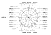
- Fig. 3A is a cross-sectional view illustrating an example of the illumination light generation apparatus 110 taken along line A-A of Fig. 2 .
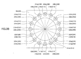
- Fig. 3B is a cross-sectional view illustrating an example of the illumination light generation apparatus 110 taken along line B-B of Fig. 2 .
- Fig. 4A is a cross-sectional view illustrating another example of the illumination light generation apparatus 110 taken along line A-A of Fig. 2 .
- Fig. 4B is a cross-sectional view illustrating another example of the illumination light generation apparatus 110 taken along line B-B of Fig. 2 .
- the illumination light generation apparatus 110 can prevent the temperature of only a specific light source included the multiple light sources of the light source unit 20 from increasing and prevent the temperatures of the multiple light sources of the light source unit 20 from increasing by using the retaining unit 50.
- the performance for cooling the multiple light sources of the light source unit 20 can be improved.
- the illumination light generation apparatus 110 generates transmitted light beams by allowing the light beams incident on the multiple lenses of the first and second lens groups 22A, 22B to be transmitted through the multiple lenses of the first and second lens groups 22A, 22B.
- the generated transmitted light beams from the first and second lens groups 22A, 22B are incident on the emission unit 30 (more specifically, the first reflection part 31A, the second reflection part 31B, or the emission part 32).
- the illumination light generation apparatus 110 may change (deflect) the propagating direction of the transmitted light beams to a direction toward the emission unit 30 by separating a center axis of the bundle of light beams radiated from the light source unit 20 and an optical axis of the collimator lenses of the lens group 22 (described in detail below). Further, the light source unit 20 may be mounted on the illumination light generation apparatus 110, so that the light beams radiated from the light source unit 20 are oriented in a direction toward the emission part 32 of the emission unit 30 (described in detail below).
- the illumination light generation apparatus 120 of the second embodiment can also attain substantially the same effects attained by the illumination light generation apparatus 110 of the first embodiment.
- the illumination light generation apparatus 130 of the third embodiment can condense the light beams reflected from the reflection member 32m by using the condenser lens 32mc, the number of times of reflecting light beams (e.g., transmitted light beams, reflected light beams) between the first and second reflection parts 31A, 31B can be reduced. Further, with the illumination light generation apparatus 130 of the third embodiment, the optical paths of the light sources of the light source unit 20 can be shortened owing to the reduction in the number of times of reflecting light beams (e.g., transmitted light beams, reflected light beams) between the first and second reflection parts 31A, 31B. Accordingly, further size-reduction can be achieved for the illumination light generation apparatus 130 of the third embodiment.
- loss of light quantity during reflection can be reduced owing to the reduction in the number of times of reflecting light beams (e.g., transmitted light beams, reflected light beams) between the first and second reflection parts 31A, 31B.
- reflecting light beams e.g., transmitted light beams, reflected light beams
- a configuration of the image projection apparatus 200 according to the first example is described with reference to Fig. 9 . It is to be noted that, because one of the above-described illumination light generation apparatuses 110, 120, 130 of the first-third embodiments of the present invention is included in the configuration of the image projection apparatus 200, parts/units different from those described in the first-third embodiments are mainly described below.
- the image projection apparatus 200 includes one of the above-described illumination light generation apparatuses 110, 120, 130 of the first-third embodiments of the present invention. Further, the image projection apparatus 200 includes a projection optical system 60 that projects an image by using a composite light beam (radiation light beam) composited by the illumination light generation apparatus (110, 120, or 130), and an image forming unit 70 that forms an image to be projected on a target projection object.
- a composite light beam radiation light beam
- the light quantity equalizing part 61 equalizes the light quantities and the like (e.g., illuminance, light intensity, brightness) of the light beams constituting the composite light beam emitted from the illumination light generation apparatus 110, 120, or 130.
- the light quantity equalizing part 61 may use, for example, a rod integrator, a quadrangular column lens, etc.
- the rod integrator may be formed of a glass rectangular column that equalizes the distribution of light intensity (luminous intensity distribution) of light beams incident on one end of the rectangular column by causing total internal reflection of the incident light beams inside the rectangular column and emits the equalized light beams from the other end of the rectangular column.
- the image processing part 72 performs various processes on the generated image according to, for example, the status/conditions (e.g., distance with respect to the target projection object, positional relationship with respect to the target projection object) for projecting the image.
- the processes performed on the generated image may include, for example, editing, deformation, adjustment, and trapezoidal distortion correction.
- the I/F unit 90 is a unit that performs input/output of data (e.g., electric signals) between the image projection apparatus 200 and an external device outside the image projection apparatus 200.
- the I/F unit 90 may receive input of data pertaining to an image to be projected from the external device (e.g., PC (Personal Computer)).
- the I/F unit 90 may also output data pertaining to the image projection apparatus 200 to the external device (e.g., PC (Personal Computer)).
- the I/F unit 90 may include an input part (not illustrated) to which data is input from the external device of the user.
- the input part may include a user interface such as an operation panel.
- the I/F unit 90 may also include an output part for outputting data to the external device.
- the output part may include a display part such as a touch panel.
- the image projection apparatus 200 generates a composite light beam by compositing multiple light beams radiated from multiple light sources (e.g., light sources 21Aa-21Ap of Fig. 3 ) by using the illumination light generation apparatus 110, 120, or 130.
- the composite light is incident on the light quantity equalizing part 61 of the projection optical system 60.
- the image projection apparatus 200 uses the light quantity equalizing part 61 to equalize the light quantities or the like of the composite light beam incident on the light quantity equalizing part 61. Then, the image projection apparatus 200 emits equalized light beams to the condenser lens part 62.
- the condenser lens part 62 allows the equalized light beams to transmit therethrough and further transmits the equalized light beams to the image forming unit 70 (more specifically, the image panel formed by the image forming unit 70). Then, the transmitted light beams emitted onto the image forming unit 70 are further transmitted through the image panel formed by the image forming unit 70. Then, the light beams transmitted through the image panel generate a projection light beam(s) corresponding to an image generated by the image generation part 71. Then, the image forming unit 70 emits the projection light beam to the projection lens part 63.
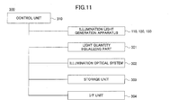
- control unit 310 controls a timing of emitting the composite light beam from the illumination light generation apparatus 110, 120, or 130 (emission timing), a light intensity (luminance) of the composite light beam emitted from the illumination light generation apparatus 110, 120, or 130, and a light quantity (amount of light) of the composite light beam emitted from the illumination light generation apparatus 110, 120, or 130 by controlling the operations/processes of the illumination light generation apparatus 110, 120, or 130. Further, the control unit 310 controls operations for radiating light to the target illumination object (including controlling of illuminance and light intensity) by controlling the operations/processes of the illumination optical system 302.
- the I/F unit 304 is a unit that performs input/output of data (e.g., electric signals) between the illumination apparatus 300 and an external device outside the illumination apparatus 300.
- the I/F unit 304 may receive input of data pertaining to the light to be radiated from the external device (e.g., PC (Personal Computer)).
- the I/F unit 304 may also output data pertaining to the illumination apparatus 300 to the external device (e.g., PC (Personal Computer)).
- the I/F unit 304 may include an input part (not illustrated) to which data is input from the external device of the user.
- the input part may include a user interface such as an operation panel.
- the I/F unit 304 may also include an output part for outputting data to the external device.
- the output part may include a display part such as a touch panel.
- the illumination apparatus 300 uses the illumination light generation apparatus 110, 120, or 130 to generate a composite light beam obtained by compositing multiple light beams radiated from multiple light sources (e.g., light sources 21Aa-21Ap in Fig. 3A ) of the light source unit 20.
- the composite light beam emitted from the illumination light generation apparatus 110, 120, or 130 is incident on the light quantity equalizing part 301.
- the incident angle of the composite light beam incident on the light quantity equalizing part 301 can be reduced.
- the diffusion of the composite light beam can be reduced owing to the reduction of the incident angle of the composite light beam incident on the light quantity equalizing part 301.
- the luminance of the target illumination object radiated by the composite light beam can be improved owing to the reduction of the diffusion of the composite light beam.
- the illumination apparatus 300 uses the light quantity equalizing part 301 to equalize the light quantities or the like of the composite light beam incident on the light quantity equalizing part 301. Then, the illumination apparatus 300 emits equalized light beams (composite light beam) to the target illumination object by way of the illumination optical system 302.
- the illumination apparatus 300 of the second example including one of the above-described illumination light generation apparatuses 110, 120, 130 of the first-third embodiments of the present invention
- the illumination apparatus 300 can attain substantially the same effects attained by the illumination light generation apparatuses 110, 120, 130 of the first-third embodiments of the present invention. Accordingly, because light usage efficiency can be improved with the illumination apparatus 300 of the second example, power consumption can be reduced. Thus, a small-sized, light-weight, high intensity illumination apparatus 300 can be obtained.
- the display apparatus 400 of the third example includes one of the above-described illumination light generation apparatuses 110, 120, 130 of the first-third embodiments of the present invention.
- a configuration of the display apparatus 400 according to the third example is described with reference to Fig. 12 . It is to be noted that, because one of the above-described illumination light generation apparatuses 110, 120, 130 of the first-third embodiments of the present invention is included in the configuration of the display apparatus 400, parts/units different from those described in the first-third embodiments are mainly described below.
- the display apparatus 400 includes one of the above-described illumination light generation apparatuses 110, 120, 130 of the first-third embodiments of the present invention. Further, the display apparatus 400 includes a light quantity equalizing part 401 that equalizes a light quantity radiated from the illumination light generation apparatus 110, 120, or 130, an image forming unit 402 that forms an image from the composite light beam emitted from the illumination light generation apparatus 110, 120, or 130, and a transmission optical system 403 that transmits the equalized light beams (composite light beam) from the light quantity equalizing part 401 to the image forming unit 402. Further, the display apparatus 400 includes a control unit 410 that controls operations/processes of each part/unit constituting the display apparatus 400.
- the display apparatus 400 may further include a storage unit 404 that stores data (e.g., operation status of the display apparatus 400, operation conditions of the display apparatus 400) therein, and an I/F (interface) unit 405 that performs input/output of data with respect to an external device outside of the display apparatus 400.
- data e.g., operation status of the display apparatus 400, operation conditions of the display apparatus 400
- I/F (interface) unit 405 that performs input/output of data with respect to an external device outside of the display apparatus 400.
- the transmission optical system 403 is an optical system that transmits equalized light beams (composite light beam) from the light quantity equalizing part 401 to the image forming unit 402.
- the transmission optical system 403 may be configured to radiate the equalized light beams to an image panel of the image forming unit 402, so that the equalized light beams serve as a backlight.
- the transmission optical system 403 may use, for example, a relay lens.
- the storage unit 404 is a unit that stores data pertaining to the display apparatus 400 such as data pertaining to operations of the display apparatus 400, data pertaining to the status of the display apparatus 400, or data pertaining to processes of the display apparatus 400.
- the storage unit 404 may use known devices such as a hard disk, a DVD, a memory, a ROM, and/or a RAM.
- the display apparatus 400 uses the illumination light generation apparatus 110, 120, or 130 to generate a composite light beam obtained by compositing multiple light beams radiated from multiple light sources (e.g., light sources 21Aa-21Ap in Fig. 3A ) of the light source unit 20.
- the composite light beam emitted from the illumination light generation apparatus 110, 120, or 130 is incident on the light quantity equalizing part 401.
- the incident angle of the composite light beam incident on the light quantity equalizing part 401 can be reduced. Further, with the display apparatus 400, the diffusion of the composite light beam radiated (emitted) to the image forming unit 402 (image panel) can be reduced owing to the reduction of the incident angle of the composite light beam incident on the light quantity equalizing part 401. Further, with the display apparatus 400, the image quality of the image to be displayed can be improved owing to the reduction of the diffusion of the composite light beam radiated (emitted) to the image forming unit 402 (image panel).
- the display apparatus 400 of the third example including one of the above-described illumination light generation apparatuses 110, 120, 130 of the first-third embodiments of the present invention
- the display apparatus 400 can attain substantially the same effects attained by the illumination light generation apparatuses 110, 120, 130 of the first-third embodiments of the present invention. Accordingly, because light usage efficiency can be improved with the display apparatus 400 of the third example, power consumption can be reduced. Thus, a small-sized, light-weight, high intensity display apparatus 400 can be obtained.
Landscapes
- Physics & Mathematics (AREA)
- General Physics & Mathematics (AREA)
- Optics & Photonics (AREA)
- Engineering & Computer Science (AREA)
- General Engineering & Computer Science (AREA)
- Non-Portable Lighting Devices Or Systems Thereof (AREA)
- Projection Apparatus (AREA)
- Arrangement Of Elements, Cooling, Sealing, Or The Like Of Lighting Devices (AREA)
Abstract
Description
- The present invention relates to an illumination light generation apparatus.
- Among various light radiation apparatuses (illumination light generation apparatuses), there is an apparatus that radiates light by compositing (combining) multiple light beams.
- Japanese Laid-Open Patent Publication No.
2011-013317 - However, with the technology taught in Japanese Laid-Open Patent Publication No.
2011-013317 2011-013317 - The present invention may provide an illumination light generation apparatus that substantially alleviates one or more of the problems caused by the limitations and disadvantages of the related art.
- Features and advantages of the present invention are set forth in the description which follows, and in part will become apparent from the description and the accompanying drawings, or may be learned by practice of the invention according to the teachings provided in the description. Objects as well as other features and advantages of the present invention will be realized and attained by an illumination light generation apparatus particularly pointed out in the specification in such full, clear, concise, and exact terms as to enable a person having ordinary skill in the art to practice the invention.
- To achieve these and other advantages and in accordance with the purpose of the invention, as embodied and broadly described herein, an embodiment of the present invention provides an illumination light generation apparatus including a light source unit including first and second light source groups that radiate a plurality of light beams, respectively, the first and second light source groups facing each other, and an emission unit that emits a composite light beam in a predetermined direction and includes a first reflection part that reflects the plurality of light beams radiated from the first light source group, and an emission part that reflects the plurality of light beams reflected from the first reflection part and the plurality of light beams radiated from the second light source group; wherein the emission part generates the composite light beam by reflecting the plurality of light beams radiated from the first light source group and the plurality of light beams radiated from the second light source group in the predetermined direction.
- Other objects, features and advantages of the present invention will become more apparent from the following detailed description when read in conjunction with the accompanying drawings; in which
-
Fig. 1 is a schematic diagram illustrating an example of an illumination light generation apparatus according to a first embodiment of the present invention; -
Fig. 2 is a schematic diagram for describing an example of an illumination light generation apparatus according to an embodiment of the present invention; -
Figs. 3A and3B are cross-sectional views for describing an example of an illumination light generation apparatus according to an embodiment of the present invention; -
Figs. 4A and 4B are cross-sectional views for describing another example of an illumination light generation apparatus according to an embodiment of the present invention; -
Figs. 5A and 5B are schematic diagrams for describing an example of a temperature adjustment unit of an illumination light generation apparatus according to an embodiment of the present invention; -
Figs. 6A and 6B are schematic diagrams for describing an emission direction of a light source unit of an illumination light generation apparatus according to an embodiment of the present invention; -
Fig. 7 is a schematic diagram for describing an example of an illumination light generation apparatus according to a second embodiment of the present invention; -
Fig. 8 is a schematic diagram for describing an example of an illumination light generation apparatus according to a third embodiment of the present invention; -
Fig. 9 is a schematic diagram illustrating an image projection apparatus according to a first example of the present invention; -
Fig. 10 is a schematic diagram for describing the image projection apparatus according to the first example of the present invention; -
Fig. 11 is a schematic diagram illustrating an illumination apparatus according to a second example of the present invention; and -
Fig. 12 is a schematic diagram illustrating a display apparatus according to a third example of the present invention. - An illustrative and non-limitative embodiment of the present invention will be described by using an illumination light generation apparatus for radiating a composite light (light beam) obtained by compositing (combining) multiple light beams with reference to accompanying drawings. The below-described illumination light generation apparatus is an apparatus that can radiate (emit, output) one or more lights from one or more light sources.
- It may also be possible to use an embodiment of the present invention in an illumination apparatus, a display apparatus, a light source apparatus, an optical scanning apparatus, an optical writing unit, an image forming (recording) apparatus, an image projection (projecting) apparatus, camera, a multifunction machine, a printer, a scanner, a facsimile machine, a bar code scanner, an on-vehicle laser radar, a wavelength variable laser, a medical laser, and others (devices, instruments, units, and the like) for compositing light, as well as an illumination light generation apparatus that will be described below.
- Additionally, identical or corresponding reference numerals are attached to identical or corresponding members or components depicted in all of accompanying drawings in the following descriptions, and redundant descriptions will be omitted. Furthermore, the drawings do not aim to illustrate a relative ratio between members or components. Therefore, it may be possible for a person skilled in the art to determine a specific dimension in light of the following non-limitative embodiment(s).
- An illumination
light generation apparatus 110 according to a first embodiment of the present invention is described with reference toFigs. 1 to 5B . - As illustrated in
Fig. 1 , the illuminationlight generation apparatus 110 includes, for example, acontrol unit 10 that controls operations/processes of the illuminationlight generation apparatus 110, alight source unit 20 including multiple light sources from which multiple light beams are radiated, and anemission unit 30 that composites (combines) multiple light beams and emits a composite light beam. Further, the illuminationlight generation apparatus 110 may also include atemperature adjustment unit 40 that adjusts the temperature of thelight source unit 20 including the multiple light sources and aretaining unit 50 that retains, for example, thelight source unit 20. - As described in detail below, the illumination
light generation apparatus 110 generates (radiates, emits) multiple light beams by using thelight source unit 20. Further, the illuminationlight generation apparatus 110 composites (combines) multiple light beams and emits the composite multiple light beams (also simply referred to as "composite light beam") by using thelight source unit 20 and theemission unit 30. Further, the illuminationlight generation apparatus 110 adjusts the temperature of thelight source unit 20 including the multiple light sources by using thetemperature adjustment unit 40. - The
control unit 10 instructs the parts/units constituting the illuminationlight generation apparatus 110 to operate and controls operations/processes of the parts/units constituting the illuminationlight generation apparatus 110. For example, thecontrol unit 10 controls a timing of radiating multiple light beams from thelight source unit 20 including the multiple light sources (radiation timing), a light intensity (luminance) of the multiple light beams radiated from thelight source unit 20, and a light quantity (amount of light) of the multiple light beams radiated from thelight source unit 20 by controlling the operations/processes of thelight source unit 20. Further, thecontrol unit 10 controls a timing of radiating the composite light beam from the emission unit 30 (emission timing), a light intensity (luminance) of the composite light beam radiated from theemission unit 30, and a light quantity (amount of light) of the composite light beam radiated from theemission unit 30 by controlling the operations/processes of theemission unit 30. Further, thecontrol unit 10 controls (adjusts) the temperature of the illuminationlight generation apparatus 110 including, for example, thelight source unit 20 by controlling the operations/processes of thetemperature adjustment unit 40. Thecontrol unit 10 may be a processing unit including, for example, a CPU (Central Processing Unit) and a memory. - The
light source unit 20 is a unit that radiates light. In this embodiment, thelight source unit 20 includes a firstlight source group 21A including multiple light sources from which multiple light beams are radiated, a secondlight source group 21B including multiple light sources from which multiple light beams are radiated, and alens group 22 including multiple lenses that converge the multiple light beams radiated from, for example, the first and/or the secondlight source group light source unit 20. - In a case where a semiconductor laser unit is used as a light source, the
light source unit 20 or the illuminationlight generation apparatus 110 including thelight source unit 20 can be formed as a small-sized high output unit or apparatus because semiconductor laser units have small size and provide high output. In addition, thelight source unit 20 or the illumination light generation apparatus 11 including thelight source unit 20 can also be formed as a small-sized high output unit or apparatus because semiconductor laser units can be integrated with high density. - Each of the first and second
light source groups light source groups retaining unit 50 is used for retaining a state where the first and secondlight source groups Fig. 2 . - More specifically, the
light source unit 20 may include, for example, the firstlight source group 21A having multiple light sources 21Aa-21Ap arranged in a substantially circular shape as illustrated inFig. 3A . Likewise, thelight source unit 20 may include, for example, the secondlight source group 21B having multiple light sources 21Ba-21Bp arranged in a substantially circular shape. Alternatively, the multiple light sources 21Aa-21Ap of the firstlight source group 21A may be arranged in a substantially quadrangular shape as illustrated inFig. 4A . Likewise, the multiple light sources 21Ba-21Bp of the secondlight source group 21B may be arranged in a substantially quadrangular shape as illustrated inFig. 4B . Alternatively, the multiple light sources 21Aa-21Ap of the firstlight source group 21A and the multiple light sources 21Ba-21Bp of the secondlight source group 21B may be arranged in other given shapes such as other circular shapes (e.g., elliptical shape), other polygonal shapes (e.g., rectangular shape), or non-polygonal shapes. -
Fig. 3A is a cross-sectional view illustrating an example of the illuminationlight generation apparatus 110 taken along line A-A ofFig. 2 .Fig. 3B is a cross-sectional view illustrating an example of the illuminationlight generation apparatus 110 taken along line B-B ofFig. 2 .Fig. 4A is a cross-sectional view illustrating another example of the illuminationlight generation apparatus 110 taken along line A-A ofFig. 2 .Fig. 4B is a cross-sectional view illustrating another example of the illuminationlight generation apparatus 110 taken along line B-B ofFig. 2 . - The
lens group 22 converges the light beams radiated from, for example, the multiple light sources 21Ba-21Bp of the secondlight source group 21B. In this embodiment, thelens group 22 includes afirst lens group 22A corresponding to the firstlight source group 21A and asecond lens group 22B corresponding to the secondlight source group 21B. Thelens group 22 may use multiple lenses such as a collimator lens, a condenser lens, a coupling lens, and/or a convex lens. In this embodiment, multiple collimator lenses (e.g., 22Aa-22Ap inFig. 3A and 22Ba-22Bp) are used as the multiple lenses constituting thelens group 22. Accordingly, thelens group 22 can converge the multiple light beams radiated from the multiple light sources 21Aa-21Ap, 21Ba-21Bp to a single area without using condenser lenses. Accordingly, the number of components of the illuminationlight generation apparatus 110 can be reduced. - As illustrated in
Figs. 2 and3A , the multiple collimator lenses 22Aa-22Ap of thefirst lens group 22A are positioned in corresponding optical paths of the multiple light beams radiated from the light sources 21Aa-21Ap of the firstlight source group 21A. Likewise, as illustrated inFigs. 2 and3B , the multiple collimator lenses 22Ba-22Bp of thesecond lens group 22B are positioned in corresponding optical paths of the multiple light beams radiated from the light sources 21Ba-21Bp of the firstlight source group 21B. Accordingly, thelens group 22 including the multiple collimator lenses 22Aa-22Ap, 22Ba-22Bp can generate multiple parallel light beams and converged light beams by converging each of the multiple light beams radiated from the multiple light sources 21Aa-21Ap, 21Ba-21Bp of the first and secondlight source groups - The
emission unit 30 is a unit that emits a composite light beam. Theemission unit 30 includes afirst reflection part 31A that reflects the multiple light beams radiated from the firstlight source group 21A and asecond reflection part 31B that reflects the multiple light beams radiated from the secondlight source group 21B. Further, theemission unit 30 includes anemission part 32 that emits light beams by reflecting light beams from thefirst reflection part 31A and reflecting light beams radiated from the secondlight source group 21B. - In this embodiment, light reflecting members are used to form the
first reflection part 31A, thesecond reflection part 31B, and theemission part 32. For example, a mirror having a thin film of metal (e.g., aluminum) deposited on a surface of a glass substrate or a silicon substrate may be used as the light reflecting member. It is, however, to be noted that other light reflecting members may be used to form thefirst reflection part 31A, thesecond reflection part 31B, and theemission part 32. - Although this embodiment describes the
emission unit 30 having a configuration including thesecond reflection part 31B, theemission unit 30 may be configured without including thesecond reflection part 31B. That is, the illuminationlight generation apparatus 110 may have a configuration in which the multiple light beams radiated from the secondlight source group 21B are directly incident on theemission unit 32. - The
first reflection part 31A reflects the light beams radiated from thelight source unit 20. In this embodiment, thefirst reflection part 31A is provided in a position facing the firstlight source group 21A as illustrated inFig. 2 . Accordingly, thefirst reflection part 31A can reflect one or more light beams transmitted through the lens group 22 (hereinafter also referred to as "transmitted light beam"). Further, thefirst reflection part 31A can reflect each of the multiple light beams radiated from the firstlight source group 21A and the secondlight source group 21B (multiple light beams reflected from thesecond reflection part 31B). By reflecting the multiple light beams with thefirst reflection part 31A, the light beams reflected from thefirst reflection part 31A (hereinafter also referred to as "reflected light beam") are incident on theemission part 32. - In a case where the multiple light sources 21Aa-21Ap of the first
light source group 21A are arranged in a substantially circular shape as illustrated inFig. 3A , thefirst reflection part 31A may include a first reflection member 31Am having a substantially circular shape as illustrated inFig. 3B . Alternatively, in a case where the multiple light sources 21Aa-21Ap of the firstlight source group 21A are arranged in a substantially quadrangular shape as illustrated inFig. 4A , thefirst reflection part 31A may include a first reflection member 31Am having a substantially quadrangular shape as illustrated inFig. 4B . It is to be noted that the shape of the first reflection member 31Am is not limited to the substantially circular or quadrangular shapes illustrated inFigs. 3B and4B . That is, the first reflection member 31Am of thefirst reflection part 31A may have a shape corresponding to, for example, the shape of the arrangement of the multiple light sources 21Aa-21Ap of the firstlight source group 21A. - The
second reflection part 31B also reflects the light beams radiated from thelight source unit 20. In this embodiment, thesecond reflection part 31B is provided in a position facing the secondlight source group 21B as illustrated inFig. 2 . Accordingly, thesecond reflection part 31B can reflect one or more transmitted light beams transmitted through thelens group 22. Further, thesecond reflection part 31B can reflect each of the multiple light beams radiated from the secondlight source group 21B. By reflecting the multiple light beams with thesecond reflection part 31B, the light beams reflected from thesecond reflection part 31B are incident on theemission part 32. - In a case where the multiple light sources 21Ba-21Bp of the second
light source group 21B are arranged in a substantially circular shape as illustrated inFig. 3B , thesecond reflection part 31B may include a second reflection member 31Bm having a substantially circular shape as illustrated inFig. 3A . Alternatively, in a case where the multiple light sources 21Ba-21Bp of the secondlight source group 21B are arranged in a substantially quadrangular shape as illustrated inFig. 4A , thesecond reflection part 31B may include a second reflection member 31Bm having a substantially quadrangular shape as illustrated inFig. 4A . It is to be noted that the shape of the second reflection member 31Bm is not limited to the substantially circular or quadrangular shapes illustrated inFigs. 3A and4A . That is, the second reflection member 31Bm of thesecond reflection part 31B may have a shape corresponding to, for example, the shape of the arrangement of the multiple light sources 21Ba-21Bp of the secondlight source group 21B. - The
emission part 32 emits the multiple light beams radiated from thelight source unit 20. In this embodiment, theemission part 32 is arranged in a position facing thefirst reflection part 31A as illustrated inFig. 2 . Accordingly, theemission part 32 can reflect (emit) the reflected beams from thefirst reflection part 31A in an emission direction Px. Further, theemission part 32 generates a composite light beam by reflecting the plural light beams radiated from the first and secondlight source groups emission part 32 generates a composite light beam by converging the plural light beams and/or reflected light beams in the emission direction Px and superimposing (compositing) the converged plural light beams and/or reflected light beams. Thereby, theemission part 32 can emit the generated composite light beam in the emission direction Px. - Further, in a case where the light sources 21Aa-21Ap of the first
light source group 21A and the light sources 21Ba-21Bp of the secondlight source group 21B are arranged in a substantially circular shape as illustrated inFigs. 3A and3B , theemission part 32 may include areflection member 32m having a substantially circular shape or a substantially elliptical shape. Alternatively, in a case where the light sources 21Aa-21Ap of the firstlight source group 21A and the light sources 21Ba-21Bp of the secondlight source group 21B are arranged in a substantially quadrangular shape as illustrated inFigs. 4A and 4B , theemission part 32 may include areflection member 32m having a substantially quadrangular shape or a substantially rectangular shape. It is, however, to be noted that the shape of thereflection member 32m is not limited to the substantially circular or quadrangular shape. That is, thereflection member 32m may have a shape corresponding to, for example, the multiple light beams incident on theemission part 32. - Further, the
emission part 32 is arranged in a position corresponding to an emission direction from which light is emitted from the illuminationlight generation apparatus 110 and corresponding to an incident angle of the multiple light beams incident on theemission part 32. That is, as illustrated inFig. 2 , theemission part 32 is to be oriented in correspondence with the emission direction Px and positioned in correspondence with the incident angles of the multiple light beams (radiated from the first and secondlight source groups emission part 32. Accordingly, theemission part 32 can emit a composite light beam formed by compositing the multiple light beams from the first and secondlight source groups - The
temperature adjustment unit 40 is a unit that adjusts the temperature of the illuminationlight generation apparatus 110, and more specifically, the temperature of thelight source unit 20. Thetemperature adjustment unit 40 includes aheat releasing member 41 to which the heat of the illumination light generation apparatus 110 (e.g., heat of the light sources in the light source unit 20) is transferred and a coolingmember 42 that cools theheat releasing member 41. - The
heat releasing member 41 can transfer the heat from the illuminationlight generation apparatus 110. That is, theheat releasing member 41 can cool the illuminationlight generation apparatus 110 including parts such as the light sources of thelight source unit 20. Theheat releasing member 41 cools the illuminationlight generation apparatus 110 by having heat transferred from the plural light sources of thelight source unit 20 to theheat releasing member 41. In this embodiment, theheat releasing member 41 is provided on a side surface of the retainingunit 50 that is opposite to the direction in which the multiple light beams are radiated from thelight source unit 20. More specifically, in the embodiment illustrated inFig. 2 , oneheat releasing member 41 is provided on a side surface of the below-described first retainingunit 50A which is positioned on an opposite side with respect to the direction in which multiple light beams are radiated from the firstlight source group 21A, and anotherheat releasing member 41 is provided on a side surface of the below-describedsecond retaining unit 50B which is positioned on an opposite side with respect to the direction in which multiple light beams are radiated from the secondlight source group 21B. - The cooling
member 42 is a unit that cools theheat releasing member 41. In this embodiment, the coolingmember 42 is provided on a side surface of theheat releasing member 41 that is opposite to a side with which the retainingmember 50 contacts theheat releasing member 41. More specifically, in this embodiment illustrated inFig. 2 , one coolingmember 42 is provided on a side surface of theheat releasing member 41 that is opposite to a side with which the first retainingmember 50A contacts theheat releasing member 41, and another coolingmember 42 is provided on a side surface of theheat releasing member 41 that is opposite to a side with which thesecond retaining member 50B contacts theheat releasing member 41. Further, as illustrated inFigs. 5A and 5B , the coolingmember 42 includes a coolingfan 42f. The coolingmember 42 generates cooling air 42fa and delivers the cooling air 42fa to theheat releasing member 41. Thereby, the coolingmember 42 can cool the illumination light generation apparatus 110 (more specifically, the heat releasing member 41) by using the cooling air 42fa. - The retaining
unit 50 is a unit that retains, for example, thelight source unit 20, theemission unit 30, and thetemperature adjustment unit 40. In this embodiment, the retainingunit 50 includes the first retainingmember 50A that retains, for example, the firstlight source group 21A and thesecond retaining member 50B that retains, for example, the secondlight source group 21B. - As illustrated in
Fig. 2 , the retaining unit 50 (50A, 50B) retains the first and secondlight source groups light source groups first lens group 22A corresponding to the firstlight source group 21A, so that thefirst lens group 22A is positioned, for example, in an optical path of the firstlight source group 21A. Likewise, the retaining unit 50 (50B) retains (supports) thesecond lens group 22B corresponding to the secondlight source group 21B, so that thesecond lens group 22B is positioned, for example, in an optical path of the secondlight source group 21B. Further, the retaining unit 50 (50A) retains thetemperature adjustment unit 40 by having a side surface that supports oneheat releasing member 41 provided on an opposite side with respect to the direction in which multiple light beams are radiated from the firstlight source group 21A. Likewise, the retaining unit 50 (50B) retains thetemperature adjustment unit 40 by having a side surface that supports anotherheat releasing member 41 provided on an opposite side with respect to the direction in which multiple light beams are radiated from the secondlight source group 21B. - Further, as illustrated in
Fig. 2 , the retainingunit 50 can retain the first and secondlight source groups light source groups unit 50 can retain the first andsecond reflection parts second reflection parts unit 50 can retain thefirst reflection part 31A and theemission part 32 in positions in which thefirst reflection part 31A and theemission part 32 are separated a predetermined distance away from each other. Each of the aforementioned predetermined distances may be set in accordance with, for example, a direction in which the light beams radiated from the light source unit 20 (e.g., light sources 21Aa-21Ap) are to be reflected and/or deflected. Further, each of the aforementioned predetermined distances may be set in accordance with, for example, the distance between the light source unit 20A (e.g., light sources 21Aa-21Ap) and the emission unit 30 (e.g.,first reflection part 31A), a direction in which multiple light beams are reflected from the emission unit 30 (e.g.,first reflection part 31A), and/or the emission direction Px of the composite light emitted from theemission unit 30. Further, each of the aforementioned predetermined distances may be set with a value obtained by, for example, an experiment or a calculation performed beforehand. - It is to be noted that each component/part of the illumination
light generation apparatus 110 may be manufactured by using, for example, a MEMS (Micro Electro Mechanical Systems) manufacturing process or a semiconductor manufacturing process. Thus, for example, thelight source unit 20, theemission unit 30, and the retainingunit 50 may be integrally molded as a united body. By molding, for example, the light source unit 20 (including the lens group 22) and the retainingunit 50 into a united body, the precision of mounting (attaching) thelight source unit 20 to the illuminationlight generation apparatus 110 can improved. - Further, with the illumination
light generation apparatus 110 according to the above-described embodiment of the present invention, thetemperature adjustment unit 40 can deliver cooling air having a substantially annular cross-section (ring-shaped profile) or a swirling flow (rotary flow pattern) corresponding to the substantially annular cross-section of the coolingmember 42 by using the coolingfan 42f. Accordingly, by using thetemperature adjustment unit 40 in the illuminationlight generation apparatus 110 according to the above-described embodiment of the present invention, the cooling air 42fa having a profile (or a flow pattern) corresponding to the substantially annular cross section of the coolingmember 42 can cool theheat releasing member 41 which is heated in correspondence with the shapes of the light sources of the first and secondlight source groups Figs. 3A ,3B or substantially quadrangular shapes illustrated inFigs. 4A, 4B ). - In other words, because the illumination
light generation apparatus 110 according to the above-described embodiment of the present invention uses the coolingfan 42f of the coolingmember 42 of thetemperature adjustment unit 40 to cool theheat releasing member 41 with the cooling air 42fa having a substantially annular cross-section (defined by the substantially annular-shaped cross section of the cooling member 42), the illumination light generation apparatus 110 (more specifically, the light source unit 20) can be efficiently cooled. Further, because the heat generated from the plural light sources of thelight source unit 20 can be transferred to the retainingunit 50, the heat can be evenly distributed (spread) in the retainingunit 50, and the distribution of the temperatures of the multiple light sources of thelight source unit 20 can become substantially uniform. Accordingly, the illuminationlight generation apparatus 110 according to the above-described embodiment of the present invention can prevent the temperature of only a specific light source included the multiple light sources of thelight source unit 20 from increasing and prevent the temperatures of the multiple light sources of thelight source unit 20 from increasing by using the retainingunit 50. Thus, the performance for cooling the multiple light sources of thelight source unit 20 can be improved. - Next, an example of an operation of radiating light with the illumination
light generation apparatus 110 according to the first embodiment of the present invention is described with reference toFigs. 2 ,Fig. 6A, and 6B . - In the below-described example, a composite light beam is emitted from the illumination
light generation apparatus 110 in one direction (direction Px inFig. 2 ). However, the direction in which the composite light beam is emitted from the illuminationlight generation apparatus 110 is not limited to the direction of the below-described example. That is, the illuminationlight generation apparatus 110 may emit light (composite light beam) in another direction according to, for example, a positional relationship between thelight source unit 20 and theemission unit 30. - As illustrated in
Fig. 2 , in order to emit a composite light beam from multiple light beams radiated from multiple light sources, first, the illuminationlight generation apparatus 110 radiates light beams from the light sources of the light source unit 20 (i.e., light sources 21Aa-21Ap, 21Ba-21Bp (Figs. 3A-3B orFigs. 4A-4B ) of the first and secondlight source groups light source unit 20 radiate the light beams, the light beams radiated from thelight source unit 20 are incident on the corresponding lenses of the first andsecond lens groups Figs. 3A-3B orFigs. 4A-4B )). Further, the illuminationlight generation apparatus 110 generates transmitted light beams by allowing the light beams incident on the multiple lenses of the first andsecond lens groups second lens groups second lens groups first reflection part 31A, thesecond reflection part 31B, or the emission part 32). - Further, the illumination
light generation apparatus 110 may generate parallel light beams (parallel transmitted light beams) by allowing the multiple light beams radiated from the light sources of thelight source unit 20 to transmit through the multiple lenses of the lens group 22 (first andsecond lens groups light generation apparatus 110 may also generate transmitted light beams other than parallel light beams. - The illumination
light generation apparatus 110 may change (deflect) the propagating direction of the transmitted light beams to a direction toward theemission unit 30 by separating a center axis of the bundle of light beams radiated from thelight source unit 20 and an optical axis of the collimator lenses of the lens group 22 (described in detail below). Further, thelight source unit 20 may be mounted on the illuminationlight generation apparatus 110, so that the light beams radiated from thelight source unit 20 are oriented in a direction toward theemission part 32 of the emission unit 30 (described in detail below). - As illustrated in
Figs. 2 and6A , the illuminationlight generation apparatus 110 radiates a bundle of light beams OS from the first and the secondlight source groups light source unit 20 and allows a bundle of light beams LS to transmit through thelens group 22, so that a center axis Ox of the bundle of light beams OS (i.e. bundle of radiated light beams prior to being transmitted through the lens group 22) and an optical axis Lx of the collimator lens of thelens group 22 are separated a predetermined distance DE away from each other. Accordingly, the illuminationlight generation apparatus 110 enables the light beams (radiated from thelight source unit 20 and transmitted through the lens group 22) LS to be deflected in a direction toward theemission unit 30 in correspondence with the amount in which the center axis Ox and the optical axis Lx are separated (i.e. predetermined distance DE). That is, the illuminationlight generation apparatus 110 allows light beams radiated from thelight source unit 20 to be incident on the emission unit 30 (more specifically, thefirst reflection part 31A, thesecond reflection part 31B, or the emission part 32) by using thelight source unit 20. Because no condenser lens, mirrors or the like are required for deflecting the light beams radiated from thelight source unit 20, the number of components of the illuminationlight generation apparatus 110 can be reduced. - Further, the
light source unit 20 may be mounted on the illuminationlight generation apparatus 110, so that the center axis of the bundle of light beams OS is inclined a predetermined angle. That is, thelight source groups light source unit 20 may be positioned in a manner that the center axis Ox of the bundle of light beams OS forms a predetermined angle (θe inFig. 6B ) with respect to a direction toward the emission unit 30 (more specifically, thefirst reflection part 31A, thesecond reflection part 31B, or the emission part 32). Accordingly, the illuminationlight generation apparatus 110 allows light beams radiated from thelight source unit 20 to be incident on the emission unit 30 (more specifically, thefirst reflection part 31A, thesecond reflection part 31B, or the emission part 32) at a predetermined incident angle by using thelight source unit 20. - Then, the illumination
light generation apparatus 110 uses thefirst reflection part 31A or thesecond reflection part 31B to reflect the transmitted light beams transmitted through the lens group 22 (more specifically, the collimator lenses 22Aa-22Ap, 22Ba-22Bp). Further, the illuminationlight generation apparatus 110 uses theemission part 32 to converge the reflected light beams reflected from the first orsecond reflection parts - More specifically, as illustrated in
Fig. 2 , with the illuminationlight generation apparatus 110 of this embodiment, multiple light beams radiated from the firstlight source group 21A are reflected from thefirst reflection part 31A and incident on theemission part 32. Further, with the illuminationlight generation apparatus 110 of this embodiment, the multiple light beams radiated from the secondlight source group 21B are reflected from thesecond reflection part 31B and incident on theemission part 32 after being reflected from thefirst reflection part 31A. Then, the illuminationlight generation apparatus 110 uses theemission part 32 to converge the incident reflected light beams from the first andsecond reflection parts light generation apparatus 110 can generate a composite light beam by superimposing the reflected light beams. The illuminationlight generation unit 110 can cause the reflected light beams to be incident on theemission part 32 after reflecting the transmitted light beams for a number of times between the first andsecond reflection parts - Then, the illumination
light generation apparatus 110 emits the composite light beam in the emission direction Px. Thereby, the operation of emitting a composite light from the illuminationlight generation apparatus 110 is completed. - Hence, with the illumination
light generation apparatus 110 according to the above-described embodiment of the present invention, a composite light beam can be generated by compositing multiple light beams radiated from multiple light sources included in multiple light source groups. Accordingly, the brightness, light intensity, illuminance, or the like of the radiated light beam (composite light beam) can be increased. Thus, a high output light beam can be radiated from the illuminationlight generation apparatus 110. Further, with the illuminationlight generation apparatus 110, because a high output light beam can be radiated by using a light source group including multiple light sources, size-reduction can be achieved with the illuminationlight generation apparatus 110 compared to an apparatus that composites multiple light beams of two light source groups after the multiple light beams have been radiated. - Next, an illumination
light generation apparatus 120 according to a second embodiment of the present invention is described. - A configuration and operation of the illumination
light generation apparatus 120 are described with reference toFigs. 1 , and3A-7 . In the second embodiment, like components/parts are denoted with like reference numerals as those of the first embodiment and are not further explained. - As illustrated in
Fig. 7 , in the illuminationlight generation apparatus 120 of this embodiment, theemission part 32 of theemission unit 30 includes a reflection member 32mb having a curved surface. In this embodiment, the illuminationlight generation apparatus 120 uses a concave mirror as the reflection member 32mb. - In this embodiment, the reflection member 32mb reflects (emits) a light beam(s) reflected from the
first reflection part 31A in the emission direction Px. In a case of reflecting the light beam(s) reflected from thefirst reflection part 31A with the reflection member 32mb, the reflection member 32mb can reflect multiple light beams reflected from thefirst reflection part 31A while converging the multiple light beams by using the curved surface. In other words, the reflection member 32mb can reduce the angle of diffusion of the multiple light beams reflected from thefirst reflection part 31A by using the curved surface. - Hence, because the illumination
light generation apparatus 120 of the second embodiment can converge reflected light beams by using the reflection member 32mb having a curved surface, the number of times of reflecting light beams (e.g., transmitted light beams, reflected light beams) between the first andsecond reflection parts light generation apparatus 120 of the second embodiment, the optical paths of the light sources of thelight source unit 20 can be shortened owing to the reduction in the number of times of reflecting light beams (e.g., transmitted light beams, reflected light beams) between the first andsecond reflection parts light generation apparatus 120 of the second embodiment. Further, with the illuminationlight generation apparatus 120 of the second embodiment, loss of light quantity during reflection can be reduced owing to the reduction in the number of times of reflecting light beams (e.g., transmitted light beams, reflected light beams) between the first andsecond reflection parts - Further, the illumination
light generation apparatus 120 of the second embodiment can also attain substantially the same effects attained by the illuminationlight generation apparatus 110 of the first embodiment. - Next, an illumination
light generation apparatus 130 according to a third embodiment of the present invention is described. - A configuration and operation of the illumination
light generation apparatus 130 are described with reference toFigs. 1 ,3A-6 , and8. In the third embodiment, like components/parts are denoted with like reference numerals as those of the first embodiment and are not further explained. - As illustrated in
Fig. 8 , in the illuminationlight generation apparatus 130 of this embodiment, theemission part 32 of theemission unit 30 further includes a condenser lens 32mc. In this embodiment, the illuminationlight generation apparatus 130 uses, for example, a convex lens as the condenser lens 32mc. - In this embodiment, the condenser lens 32mc can condense (converge) light beams reflected from the
reflection member 32m of theemission part 32. That is, the condenser lens 32mc can condense the multiple light beams radiated from the multiple light sources of thelight source unit 20 and shorten a focal distance of the condensed light beams. - Hence, because the illumination
light generation apparatus 130 of the third embodiment can condense the light beams reflected from thereflection member 32m by using the condenser lens 32mc, the number of times of reflecting light beams (e.g., transmitted light beams, reflected light beams) between the first andsecond reflection parts light generation apparatus 130 of the third embodiment, the optical paths of the light sources of thelight source unit 20 can be shortened owing to the reduction in the number of times of reflecting light beams (e.g., transmitted light beams, reflected light beams) between the first andsecond reflection parts light generation apparatus 130 of the third embodiment. Further, with the illuminationlight generation apparatus 130 of the third embodiment, loss of light quantity during reflection can be reduced owing to the reduction in the number of times of reflecting light beams (e.g., transmitted light beams, reflected light beams) between the first andsecond reflection parts - Further, the illumination
light generation apparatus 130 of the third embodiment can also attain substantially the same effects attained by the illuminationlight generation apparatus 110 of the first embodiment. - Next, an
image projection apparatus 200 according to a first example of the present invention is described. Theimage projection apparatus 200 of the first example includes one of the above-described illuminationlight generation apparatuses image projection apparatus 200 of the first example may be any projection apparatus (projector) that projects an image on a target projection object (including extended projection) by using a composite light beam formed by compositing multiple light beams. - A configuration of the
image projection apparatus 200 according to the first example is described with reference toFig. 9 . It is to be noted that, because one of the above-described illuminationlight generation apparatuses image projection apparatus 200, parts/units different from those described in the first-third embodiments are mainly described below. - As illustrated in
Fig. 9 , theimage projection apparatus 200 includes one of the above-described illuminationlight generation apparatuses image projection apparatus 200 includes a projectionoptical system 60 that projects an image by using a composite light beam (radiation light beam) composited by the illumination light generation apparatus (110, 120, or 130), and animage forming unit 70 that forms an image to be projected on a target projection object. Further, theimage projection apparatus 200 includes acontrol unit 210 that controls operations/processes of each part/unit constituting theimage projection apparatus 200, astorage unit 80 that stores data (e.g., operation status of theimage projection apparatus 200, operation conditions of the image projection apparatus 200) therein, and an I/F (interface)unit 90 that performs input/output of data with respect to an external device outside of theimage projection apparatus 200. - The
control unit 210 instructs the parts/units constituting theimage projection apparatus 200 to operate and controls operations/processes of the parts/units constituting theimage projection apparatus 200. For example, thecontrol unit 210 controls a timing of radiating multiple light beams from thelight source unit 20 including the multiple light sources (radiation timing), light intensity (luminance) of the multiple light beams radiated from thelight source unit 20, and a light quantity (amount of light) of the multiple light beams radiated from thelight source unit 20 by controlling the operations/processes of thelight source unit 20. Further, thecontrol unit 210 controls a timing of emitting the composite light beam from the illuminationlight generation apparatus light generation apparatus light generation apparatus light source unit 20. Further, thecontrol unit 210 controls operations pertaining to an image to be projected by controlling the operations/processes of the projectionoptical system 60 and theimage forming unit 70. - It is to be noted that a program (e.g., control program, application) may be stored beforehand in, for example, the
storage unit 80, so that thecontrol unit 210 can control the projectionoptical system 60 and theimage forming unit 70 by using the program. Further, thecontrol unit 210 may control operations of, for example, the illuminationlight generation apparatus optical system 60, and theimage forming unit 70 based on data input from an input unit (not illustrated) included in the I/F unit 90. - The projection
optical system 60 is a unit for projecting an image on a target projection object by using a composite light beam composited (combined) by the illuminationlight generation apparatus optical system 60 includes a lightquantity equalizing part 61 for equalizing, for example, light quantities and the like (e.g., illuminance, light intensity, brightness) of the light beams constituting the composite light emitted from the illuminationlight generation apparatus condenser lens part 62 for radiating the light beams having their light quantities and the like equalized by the lightquantity equalizing part 61 to an image formed by theimage forming unit 70, and aprojection lens part 63 for projecting light beams transmitted through the image formed by theimage forming unit 70. - The light
quantity equalizing part 61 equalizes the light quantities and the like (e.g., illuminance, light intensity, brightness) of the light beams constituting the composite light beam emitted from the illuminationlight generation apparatus quantity equalizing part 61 may use, for example, a rod integrator, a quadrangular column lens, etc. For example, the rod integrator may be formed of a glass rectangular column that equalizes the distribution of light intensity (luminous intensity distribution) of light beams incident on one end of the rectangular column by causing total internal reflection of the incident light beams inside the rectangular column and emits the equalized light beams from the other end of the rectangular column. - The
condenser lens part 62 radiates the light beams emitted from the lightquantity equalizing part 62 to the image formed by theimage forming unit 70. That is, thecondenser lens part 62 radiates light beams equalized by the lightquantity equalizing part 61 to the image (e.g., image panel) formed by theimage forming unit 70. Thecondenser lens part 62 may use, for example, a relay lens. - The
projection lens part 63 projects light beams transmitted through the image formed by theimage forming unit 70. In this embodiment, theprojection lens part 63 projects (forms) an image on a surface of the target projection object with the light beams transmitted through the image formed by theimage forming unit 70. Theprojection lens part 63 may increase or reduce the size of the image to be projected (magnification/reduction) by using multiple lenses. - The
image forming unit 70 is a unit that forms an image to be projected. In this embodiment, theimage forming unit 70 includes animage generation part 71 for generating the image to be projected, and an image processing part 72 for processing the image generated by theimage generation part 71. - The
image generation part 71 generates the image to be projected based on data stored in the storage unit 80 (e.g., image data) and/or data input from the I/F unit 90. In this embodiment, theimage generation part 71 displays the generated image on a transmission type image panel formed in correspondence with modulation signals. It is, however, to be noted that the generated image may be displayed on an image panel other than the transmission type image panel. For example, theimage generation part 71 may display the generated image on a reflection type panel or a DMD (Digital Micromirror Device) type panel. - The image processing part 72 performs various processes on the generated image according to, for example, the status/conditions (e.g., distance with respect to the target projection object, positional relationship with respect to the target projection object) for projecting the image. The processes performed on the generated image may include, for example, editing, deformation, adjustment, and trapezoidal distortion correction.
- The
storage unit 80 is a unit that stores data pertaining to theimage projection apparatus 200 such as data pertaining to operations of theimage projection apparatus 200, data pertaining to the status of theimage projection apparatus 200, or data pertaining to processes of theimage projection apparatus 200. Thestorage unit 80 may use known devices such as a hard disk, a DVD (Digital Versatile Disc), a memory, a ROM (Read Only Memory), and/or a RAM (Random Access Memory). - The I/
F unit 90 is a unit that performs input/output of data (e.g., electric signals) between theimage projection apparatus 200 and an external device outside theimage projection apparatus 200. The I/F unit 90 may receive input of data pertaining to an image to be projected from the external device (e.g., PC (Personal Computer)). The I/F unit 90 may also output data pertaining to theimage projection apparatus 200 to the external device (e.g., PC (Personal Computer)). The I/F unit 90 may include an input part (not illustrated) to which data is input from the external device of the user. The input part may include a user interface such as an operation panel. Further, the I/F unit 90 may also include an output part for outputting data to the external device. The output part may include a display part such as a touch panel. - Next, an operation of projecting an image with the
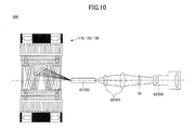
image projection apparatus 200 according to the first example is described with reference toFig. 10 . - As illustrated in
Fig. 10 , theimage projection apparatus 200 generates a composite light beam by compositing multiple light beams radiated from multiple light sources (e.g., light sources 21Aa-21Ap ofFig. 3 ) by using the illuminationlight generation apparatus quantity equalizing part 61 of the projectionoptical system 60. - The
image projection apparatus 200 can generate a composite light beam having a small-sized cross section owing to the use of the illuminationlight generation apparatus image projection apparatus 200 can generate a high density - Accordingly, with the
image projection apparatus 200 of the first example, the incident angle of the composite light beam incident on the projection optical system 60 (more specifically, the light quantity equalizing part 61) can be reduced. Therefore, the diffusion of the light beams incident on the image forming unit 70 (more specifically, the image panel formed by the image forming unit 70) can be reduced. Further, with theimage projection apparatus 200, a projection lens having a small NA (Numerical Aperture) or a large F (focal) number can be used owing to the reduction of the diffusion the light beams incident on the image forming unit 70 (more specifically, the image panel formed by the image forming unit 70). That is, the designing and manufacturing of the lens of theprojection lens part 63 can be facilitated by using theimage projection apparatus 200. - Then, the
image projection apparatus 200 uses the lightquantity equalizing part 61 to equalize the light quantities or the like of the composite light beam incident on the lightquantity equalizing part 61. Then, theimage projection apparatus 200 emits equalized light beams to thecondenser lens part 62. - Then, the
condenser lens part 62 allows the equalized light beams to transmit therethrough and further transmits the equalized light beams to the image forming unit 70 (more specifically, the image panel formed by the image forming unit 70). Then, the transmitted light beams emitted onto theimage forming unit 70 are further transmitted through the image panel formed by theimage forming unit 70. Then, the light beams transmitted through the image panel generate a projection light beam(s) corresponding to an image generated by theimage generation part 71. Then, theimage forming unit 70 emits the projection light beam to theprojection lens part 63. - Then, the
projection lens part 63 emits (transmits) the projection light beam(s) to a target projection object. Thereby, theimage projection apparatus 200 can project an image corresponding to the image generated by the image forming unit 70 (more specifically, the image generation part 71) on a surface of the target projection object. - Hence, with the
image projection apparatus 200 of the first example including one of the above-described illuminationlight generation apparatuses image projection apparatus 200 can attain substantially the same effects attained by the illuminationlight generation apparatuses - Further, with the
image projection apparatus 200 of the first example, a projection lens having a small NA (Numerical Aperture) or a large F (focal) number can be used because the incident angle of the composite beam incident on the projection optical system 60 (including the rod integrator) can be reduced. That is, the designing and manufacturing of the lens of theprojection lens part 63 can be facilitated, cooling efficiency can be improved, and light usage efficiency can be improved by using theimage projection apparatus 200. Further, owing to the improvement of light usage efficiency, power consumption can be reduced. Thus, a small-sized, light-weight, high intensityimage projection apparatus 200 can be obtained. - Next, an
illumination apparatus 200 according to a second example of the present invention is described. Theillumination apparatus 200 of the second example includes one of the above-described illuminationlight generation apparatuses - A configuration of the
illumination apparatus 300 according to the second example is described with reference toFig. 11 . It is to be noted that, because one of the above-described illuminationlight generation apparatuses illumination apparatus 300, parts/units different from those described in the first-third embodiments are mainly described below. - As illustrated in
Fig. 11 , theillumination apparatus 300 includes one of the above-described illuminationlight generation apparatuses illumination apparatus 300 includes a lightquantity equalizing part 301 that equalizes a light quantity radiated from the illuminationlight generation apparatus optical system 302 that radiates light beams having their light quantities equalized by the light quantity equalizing part 301 (composite light beam) to a target illumination object. Further, theillumination apparatus 300 includes acontrol unit 310 that controls operations/processes of each part/unit constituting theillumination apparatus 300. Theillumination apparatus 300 may further include astorage unit 303 that stores data (e.g., operation status of theillumination apparatus 300, operation conditions of the illumination apparatus 300) therein, and an I/F (interface)unit 304 that performs input/output of data with respect to an external device outside of theillumination apparatus 300. - The
control unit 310 instructs the parts/units constituting theillumination apparatus 300 to operate and controls operations/processes of the parts/units constituting theillumination apparatus 300. For example, thecontrol unit 310 controls a timing of radiating multiple light beams from thelight source unit 20 including the multiple light sources (radiation timing), a light intensity (luminance) of the multiple light beams radiated from thelight source unit 20, and a light quantity (amount of light) of the multiple light beams radiated from thelight source unit 20 by controlling the operations/processes of the illuminationlight generation apparatus control unit 310 controls a timing of emitting the composite light beam from the illuminationlight generation apparatus light generation apparatus light generation apparatus light generation apparatus control unit 310 controls operations for radiating light to the target illumination object (including controlling of illuminance and light intensity) by controlling the operations/processes of the illuminationoptical system 302. - It is to be noted that a program (e.g., control program, application) may be stored beforehand in, for example, the
storage unit 303, so that thecontrol unit 310 can control operations of the parts/units of theillumination apparatus 300 by using the program. Further, thecontrol unit 210 may control operations of the parts/units of theillumination apparatus 300 based on data input from an input unit (not illustrated) included in the I/F unit 304. - The light
quantity equalizing part 301 equalizes the light quantities and the like (e.g., illuminance, light intensity, brightness) of the light beams constituting the composite light beam emitted from the illuminationlight generation apparatus quantity equalizing part 301 are incident on the radiationoptical system 302. The lightquantity equalizing part 301 may use, for example, a light tunnel including, for example, a rod mirror, a kaleidoscope, a light pipe, and other members that allow light to be transmitted therethrough. - The illumination
optical system 302 is an optical system that illuminates the target illumination object by radiating (emitting) the equalized light beams (composite light beam) from the lightquantity equalizing part 301 to the target illumination object. The radiationoptical system 302 may use, for example, a relay lens, and/or an illumination lens. - The
storage unit 303 is a unit that stores data pertaining to theillumination apparatus 300 such as data pertaining to operations of theillumination apparatus 300, data pertaining to the status of theillumination apparatus 300, or data pertaining to processes of theillumination apparatus 300. Thestorage unit 303 may use known devices such as a hard disk, a DVD, a memory, a ROM, and/or a RAM. - The I/
F unit 304 is a unit that performs input/output of data (e.g., electric signals) between theillumination apparatus 300 and an external device outside theillumination apparatus 300. The I/F unit 304 may receive input of data pertaining to the light to be radiated from the external device (e.g., PC (Personal Computer)). The I/F unit 304 may also output data pertaining to theillumination apparatus 300 to the external device (e.g., PC (Personal Computer)). The I/F unit 304 may include an input part (not illustrated) to which data is input from the external device of the user. The input part may include a user interface such as an operation panel. Further, the I/F unit 304 may also include an output part for outputting data to the external device. The output part may include a display part such as a touch panel. - Next, an operation of radiating (emitting) a composite light beam to a target illumination object with the
illumination apparatus 300 according to the second example is described. - First, the
illumination apparatus 300 uses the illuminationlight generation apparatus Fig. 3A ) of thelight source unit 20. The composite light beam emitted from the illuminationlight generation apparatus quantity equalizing part 301. - The
illumination apparatus 300 can generate a composite light beam having a small-sized cross section owing to the use of the illuminationlight generation apparatus illumination apparatus 300 can generate a high density (high intensity) composite light beam by using the illuminationlight generation apparatus - Accordingly, with the
illumination apparatus 300 of the second example, the incident angle of the composite light beam incident on the lightquantity equalizing part 301 can be reduced. Further, with theillumination apparatus 300, the diffusion of the composite light beam can be reduced owing to the reduction of the incident angle of the composite light beam incident on the lightquantity equalizing part 301. Further, with theillumination apparatus 300, the luminance of the target illumination object radiated by the composite light beam can be improved owing to the reduction of the diffusion of the composite light beam. - Then, the
illumination apparatus 300 uses the lightquantity equalizing part 301 to equalize the light quantities or the like of the composite light beam incident on the lightquantity equalizing part 301. Then, theillumination apparatus 300 emits equalized light beams (composite light beam) to the target illumination object by way of the illuminationoptical system 302. - Hence, with the
illumination apparatus 300 of the second example including one of the above-described illuminationlight generation apparatuses illumination apparatus 300 can attain substantially the same effects attained by the illuminationlight generation apparatuses illumination apparatus 300 of the second example, power consumption can be reduced. Thus, a small-sized, light-weight, highintensity illumination apparatus 300 can be obtained. - Next, a
display apparatus 400 according to a third example of the present invention is described. Thedisplay apparatus 400 of the third example includes one of the above-described illuminationlight generation apparatuses - A configuration of the
display apparatus 400 according to the third example is described with reference toFig. 12 . It is to be noted that, because one of the above-described illuminationlight generation apparatuses display apparatus 400, parts/units different from those described in the first-third embodiments are mainly described below. - As illustrated in
Fig. 12 , thedisplay apparatus 400 includes one of the above-described illuminationlight generation apparatuses display apparatus 400 includes a lightquantity equalizing part 401 that equalizes a light quantity radiated from the illuminationlight generation apparatus image forming unit 402 that forms an image from the composite light beam emitted from the illuminationlight generation apparatus optical system 403 that transmits the equalized light beams (composite light beam) from the lightquantity equalizing part 401 to theimage forming unit 402. Further, thedisplay apparatus 400 includes acontrol unit 410 that controls operations/processes of each part/unit constituting thedisplay apparatus 400. Thedisplay apparatus 400 may further include astorage unit 404 that stores data (e.g., operation status of thedisplay apparatus 400, operation conditions of the display apparatus 400) therein, and an I/F (interface)unit 405 that performs input/output of data with respect to an external device outside of thedisplay apparatus 400. - The
control unit 410 instructs the parts/units constituting thedisplay apparatus 400 to operate and controls operations/processes of the parts/units constituting thedisplay apparatus 400. For example, thecontrol unit 410 controls a timing of radiating multiple light beams from thelight source unit 20 including the multiple light sources (radiation timing), a light intensity (luminance) of the multiple light beams radiated from thelight source unit 20, and a light quantity (amount of light) of the multiple light beams radiated from thelight source unit 20 by controlling the operations/processes of the illuminationlight generation apparatus control unit 410 controls a timing of emitting the composite light beam from the illuminationlight generation apparatus light generation apparatus light generation apparatus light generation apparatus control unit 410 controls operations for displaying an image (including controlling of the brightness or size of the image to be displayed) by controlling the operations/processes of theimage forming unit 402 and the transmissionoptical system 403. - It is to be noted that a program (e.g., control program, application) may be stored beforehand in, for example, the
storage unit 404, so that thecontrol unit 410 can control operations of the parts/units of thedisplay apparatus 400 by using the program. Further, thecontrol unit 410 may control operations of the parts/units of thedisplay apparatus 400 based on data input from an input unit (not illustrated) included in the I/F unit 405. - The light
quantity equalizing part 401 equalizes the light quantities and the like (e.g., illuminance, light intensity, brightness) of the light beams constituting the composite light beam emitted from the illuminationlight generation apparatus quantity equalizing part 401 are incident on the transmissionoptical system 403. The lightquantity equalizing part 401 may use, for example, a light tunnel including, for example, a rod mirror, a kaleidoscope, a light pipe, and other members that allow light to be transmitted therethrough. - The
image forming unit 402 is a unit that forms an image to be displayed. In this embodiment, theimage forming unit 402 generates the image to be displayed based on data stored in the storage unit 404 (e.g., image data) and/or data input from the I/F unit 405. For example, theimage forming unit 402 may be configured to display a full-color image by using image forming elements arranged in a matrix (image panel). - The transmission
optical system 403 is an optical system that transmits equalized light beams (composite light beam) from the lightquantity equalizing part 401 to theimage forming unit 402. For example, the transmissionoptical system 403 may be configured to radiate the equalized light beams to an image panel of theimage forming unit 402, so that the equalized light beams serve as a backlight. The transmissionoptical system 403 may use, for example, a relay lens. - The
storage unit 404 is a unit that stores data pertaining to thedisplay apparatus 400 such as data pertaining to operations of thedisplay apparatus 400, data pertaining to the status of thedisplay apparatus 400, or data pertaining to processes of thedisplay apparatus 400. Thestorage unit 404 may use known devices such as a hard disk, a DVD, a memory, a ROM, and/or a RAM. - The I/
F unit 405 is a unit that performs input/output of data (e.g., electric signals) between thedisplay apparatus 400 and an external device outside thedisplay apparatus 400. The I/F unit 405 may receive input of data pertaining to the light to be radiated from the external device (e.g., PC (Personal Computer)). The I/F unit 405 may also output data pertaining to thedisplay apparatus 400 to the external device (e.g., PC (Personal Computer)). The I/F unit 405 may include an input part (not illustrated) to which data is input from the external device of the user. The input part may include a user interface such as an operation panel. Further, the I/F unit 405 may also include an output part for outputting data to the external device. The output part may include a display part such as a touch panel. - Next, an operation of displaying an image with the
display apparatus 400 according to the third example is described. - First, the
display apparatus 400 uses the illuminationlight generation apparatus Fig. 3A ) of thelight source unit 20. The composite light beam emitted from the illuminationlight generation apparatus quantity equalizing part 401. - The
display apparatus 400 can generate a composite light beam having a small-sized cross section owing to the use of the illuminationlight generation apparatus display apparatus 400 can generate a high density (high intensity) composite light beam by using the illuminationlight generation apparatus - Accordingly, with the
display apparatus 400 of the third example, the incident angle of the composite light beam incident on the lightquantity equalizing part 401 can be reduced. Further, with thedisplay apparatus 400, the diffusion of the composite light beam radiated (emitted) to the image forming unit 402 (image panel) can be reduced owing to the reduction of the incident angle of the composite light beam incident on the lightquantity equalizing part 401. Further, with thedisplay apparatus 400, the image quality of the image to be displayed can be improved owing to the reduction of the diffusion of the composite light beam radiated (emitted) to the image forming unit 402 (image panel). - Then, the
display apparatus 400 uses the lightquantity equalizing part 401 to equalize the light quantities or the like of the composite light beam incident on the lightquantity equalizing part 401. Then, thedisplay apparatus 400 emits equalized light beams (composite light beam) to the image forming unit 402 (image panel) by way of the transmissionoptical system 403. Thereby, thedisplay apparatus 400 can display an image on the image forming unit 402 (more specifically, an image panel of the image forming unit 402) by using the composite light beam incident on theimage forming unit 402. - Hence, with the
display apparatus 400 of the third example including one of the above-described illuminationlight generation apparatuses display apparatus 400 can attain substantially the same effects attained by the illuminationlight generation apparatuses display apparatus 400 of the third example, power consumption can be reduced. Thus, a small-sized, light-weight, highintensity display apparatus 400 can be obtained. - The present invention is not limited to the specifically disclosed embodiments, and variations and modifications may be made without departing from the scope of the present invention.
Claims (12)
- An illumination light generation apparatus comprising:a light source unit including first and second light source groups that radiate a plurality of light beams, respectively, the first and second light source groups facing each other; andan emission unit that emits a composite light beam in a predetermined direction and includes
a first reflection part that reflects the plurality of light beams radiated from the first light source group, and
an emission part that reflects the plurality of light beams reflected from the first reflection part and the plurality of light beams radiated from the second light source group;wherein the emission part generates the composite light beam by reflecting the plurality of light beams radiated from the first light source group and the plurality of light beams radiated from the second light source group in the predetermined direction. - The illumination light generation apparatus as claimed in claim 1, wherein
the emission unit further includes a second reflection part that faces the first reflection part,
the second reflection part is configured to reflect the plurality of light beams radiated from the second light source group to the first reflection part, and
the first reflection part is configured to reflect the plurality of light beams reflected from the second reflection part to the emission part. - The illumination light generation apparatus as claimed in claim 1 or claim 2, wherein
the emission part includes a reflection member that reflects the plurality of light beams radiated from the first light source group and the plurality of light beams radiated from the second light source group,
wherein the reflection member is positioned in accordance with the predetermined direction and an incident angle formed by the plurality of light beams radiated from the first light source group and the plurality of light beams radiated from the second light source group with respect to the emission part. - The illumination light generation apparatus as claimed in claim 3, characterized in that the reflection member has a curved surface.
- The illumination light generation apparatus as claimed in one of claims 1 to 4,
characterized in that each of the first and second light source groups include a plurality of light sources from which the plurality of light beams are radiated, and
the plurality of light sources are positioned to radiate the plurality of light beams at a predetermined angle relative to the first reflection part or the second reflection part. - The illumination light generation apparatus as claimed in one of claims 1 to 4, wherein
each of the first and second light source groups include a plurality of semiconductor laser units from which the plurality of light beams are radiated, and
the light source unit further includes a plurality of collimator lenses that generate parallel light beams or converged light beams by converging the plurality of light beams. - The illumination light generation apparatus as claimed in claim 6, wherein an optical axis of the plurality of collimator lenses is separated a predetermined distance away from a center axis of the plurality of light beams radiated from the first and second light source groups.
- The illumination light generation apparatus as claimed in one of claims 1 to 4, further comprising:a retaining unit that retains the light source unit;wherein each of the first and second light source groups include a plurality of light sources from which the plurality of light beams are radiated, andwherein the retaining unit is configured to retain the light source unit, so that the plurality of light sources are arranged in a substantially circular shape or a polygonal shape.
- The illumination light generation apparatus as claimed in claim 8, further comprising:a temperature adjustment unit that delivers cooling air to the light source unit;wherein the retaining unit is further configured to retain the temperature adjustment unit, andwherein the temperature adjustment unit is configured to deliver the cooling air with a substantially annular profile or a flow pattern that corresponds to the substantially circular shape or the polygonal shape of the plurality of light sources.
- An image projection apparatus comprising:the illumination light generation apparatus as claimed in one of claims 1 to 9;a projection optical system that projects an image by using the composite light beam generated by the illumination light generation apparatus; andan image forming unit that forms the image to be projected by the projection optical system.
- An illumination apparatus comprising:the illumination light generation apparatus as claimed in one of claims 1 to 9;a light quantity equalizing part that generates an equalized light beam by equalizing a light quantity of the composite light beam emitted from the illumination light generation apparatus; andan illumination optical system that radiates the equalized light beam to a target illumination object.
- A display apparatus comprising:the illumination light generation apparatus as claimed in one of claims 1 to 9;a light quantity equalizing part that generates an equalized light beam by equalizing a light quantity of the composite light beam emitted from the illumination light generation apparatus;a transmission optical system that transmits the equalized light beam generated by the light quantity equalizing part; andan image forming unit that forms an image by using the equalized light composite light beam transmitted by the transmission optical system.
Applications Claiming Priority (2)
| Application Number | Priority Date | Filing Date | Title |
|---|---|---|---|
| JP2012180639 | 2012-08-16 | ||
| JP2013120878A JP6160274B2 (en) | 2012-08-16 | 2013-06-07 | Image projection device |
Publications (2)
| Publication Number | Publication Date |
|---|---|
| EP2698661A1 true EP2698661A1 (en) | 2014-02-19 |
| EP2698661B1 EP2698661B1 (en) | 2017-02-22 |
Family
ID=49035286
Family Applications (1)
| Application Number | Title | Priority Date | Filing Date |
|---|---|---|---|
| EP13179974.4A Not-in-force EP2698661B1 (en) | 2012-08-16 | 2013-08-09 | Illumination light generation apparatus |
Country Status (4)
| Country | Link |
|---|---|
| US (1) | US9121570B2 (en) |
| EP (1) | EP2698661B1 (en) |
| JP (1) | JP6160274B2 (en) |
| CN (1) | CN103631019B (en) |
Families Citing this family (13)
| Publication number | Priority date | Publication date | Assignee | Title |
|---|---|---|---|---|
| JP6186786B2 (en) * | 2013-03-22 | 2017-08-30 | セイコーエプソン株式会社 | Light source device and projector |
| JP6233687B2 (en) | 2013-08-12 | 2017-11-22 | 株式会社リコー | Light source device and image projection device provided with the same |
| JP6452027B2 (en) | 2013-10-23 | 2019-01-16 | 株式会社リコー | Light source device and image projection device provided with the same |
| JP6476667B2 (en) | 2013-11-01 | 2019-03-06 | 株式会社リコー | Light source device and projector using the same |
| WO2015122075A1 (en) | 2014-02-17 | 2015-08-20 | 株式会社リコー | Optical irradiation device and image display device equipped with same |
| JP6394693B2 (en) | 2014-03-18 | 2018-10-03 | 株式会社リコー | Light source device and image projection apparatus having the light source device |
| JP6547270B2 (en) | 2014-10-10 | 2019-07-24 | 株式会社リコー | Light source device and image projector having the light source device |
| JP6206560B2 (en) | 2015-09-28 | 2017-10-04 | 株式会社リコー | system |
| CN110319415A (en) * | 2018-03-29 | 2019-10-11 | 坦德科技股份有限公司 | Has the laser vehicle lamp light source module of light ringing |
| JP7268421B2 (en) | 2019-03-18 | 2023-05-08 | 株式会社リコー | Light source optical system, light source device and image projection device |
| CN111722465A (en) | 2019-03-20 | 2020-09-29 | 株式会社理光 | Light source device, image projection device, and light source optical system |
| US11720010B2 (en) | 2020-12-07 | 2023-08-08 | Ricoh Company, Ltd. | Light source device and projection device |
| JP7625913B2 (en) | 2021-03-17 | 2025-02-04 | 株式会社リコー | Light source device and image projection device |
Citations (7)
| Publication number | Priority date | Publication date | Assignee | Title |
|---|---|---|---|---|
| US6356390B1 (en) * | 2000-06-22 | 2002-03-12 | Thomson Licensing, S.A. | Light valve light source |
| EP1333308A2 (en) * | 2002-02-01 | 2003-08-06 | Samsung Electronics Co., Ltd. | Compact illumination system and projection display device employing the same |
| WO2006027621A2 (en) * | 2004-09-11 | 2006-03-16 | Apticol Limited | Light engine for projection application |
| JP2006138952A (en) * | 2004-11-10 | 2006-06-01 | Sanyo Electric Co Ltd | Illuminator and projection type video display device |
| US20100103519A1 (en) * | 2008-10-28 | 2010-04-29 | Silverstein Barry D | Etendue maintaining polarization switching system and related methods |
| WO2011006501A1 (en) * | 2009-07-13 | 2011-01-20 | Martin Professional A/S | Color-combining illumination device |
| JP2011013317A (en) | 2009-06-30 | 2011-01-20 | Casio Computer Co Ltd | Light source unit, light source apparatus, and projector |
Family Cites Families (11)
| Publication number | Priority date | Publication date | Assignee | Title |
|---|---|---|---|---|
| WO1999049358A1 (en) * | 1998-03-26 | 1999-09-30 | Mitsubishi Denki Kabushiki Kaisha | Image display and light-emitting device |
| DE10341626B4 (en) * | 2003-09-10 | 2016-06-02 | Carl Zeiss Jena Gmbh | Illumination module for color image display |
| CA2552749A1 (en) * | 2004-11-12 | 2006-05-26 | Ryan Waters | Led light apparatus and methodology |
| JP2006163281A (en) | 2004-12-10 | 2006-06-22 | Ricoh Co Ltd | Projector device |
| DE102005031710B4 (en) | 2005-07-05 | 2014-12-24 | Sick Ag | Optoelectronic sensor |
| JP4909546B2 (en) * | 2005-08-12 | 2012-04-04 | 株式会社リコー | Illumination device, light modulation device, and projection display device |
| JP2008090016A (en) | 2006-10-03 | 2008-04-17 | Canon Inc | Illumination device and projection-type image display device |
| EP2573812B1 (en) * | 2006-10-12 | 2017-08-16 | Panasonic Intellectual Property Management Co., Ltd. | Light-emitting apparatus |
| US7905605B2 (en) * | 2006-12-13 | 2011-03-15 | Koninklijke Philips Electronics N.V. | Multi-primary LED projection system |
| EP2235434A4 (en) * | 2007-12-24 | 2011-04-20 | Moore Benjamin & Co | System for representing colors including an integrating light capsule |
| JP5166580B2 (en) * | 2010-08-06 | 2013-03-21 | ポスコ アイシーティ カンパニー リミテッド | Optical semiconductor lighting device |
-
2013
- 2013-06-07 JP JP2013120878A patent/JP6160274B2/en not_active Expired - Fee Related
- 2013-08-06 US US13/960,170 patent/US9121570B2/en active Active
- 2013-08-09 EP EP13179974.4A patent/EP2698661B1/en not_active Not-in-force
- 2013-08-16 CN CN201310552669.7A patent/CN103631019B/en not_active Expired - Fee Related
Patent Citations (7)
| Publication number | Priority date | Publication date | Assignee | Title |
|---|---|---|---|---|
| US6356390B1 (en) * | 2000-06-22 | 2002-03-12 | Thomson Licensing, S.A. | Light valve light source |
| EP1333308A2 (en) * | 2002-02-01 | 2003-08-06 | Samsung Electronics Co., Ltd. | Compact illumination system and projection display device employing the same |
| WO2006027621A2 (en) * | 2004-09-11 | 2006-03-16 | Apticol Limited | Light engine for projection application |
| JP2006138952A (en) * | 2004-11-10 | 2006-06-01 | Sanyo Electric Co Ltd | Illuminator and projection type video display device |
| US20100103519A1 (en) * | 2008-10-28 | 2010-04-29 | Silverstein Barry D | Etendue maintaining polarization switching system and related methods |
| JP2011013317A (en) | 2009-06-30 | 2011-01-20 | Casio Computer Co Ltd | Light source unit, light source apparatus, and projector |
| WO2011006501A1 (en) * | 2009-07-13 | 2011-01-20 | Martin Professional A/S | Color-combining illumination device |
Also Published As
| Publication number | Publication date |
|---|---|
| JP2014056812A (en) | 2014-03-27 |
| US20140049755A1 (en) | 2014-02-20 |
| JP6160274B2 (en) | 2017-07-12 |
| CN103631019A (en) | 2014-03-12 |
| EP2698661B1 (en) | 2017-02-22 |
| CN103631019B (en) | 2016-02-10 |
| US9121570B2 (en) | 2015-09-01 |
Similar Documents
| Publication | Publication Date | Title |
|---|---|---|
| EP2698661B1 (en) | Illumination light generation apparatus | |
| JP6007861B2 (en) | Optical deflector and image projection apparatus | |
| EP2664958B1 (en) | Light source apparatus and image projection apparatus | |
| JP2014053285A5 (en) | ||
| US9857672B2 (en) | Light source unit, lighting apparatus and image projection apparatus | |
| US9557631B2 (en) | Light source unit and image projection apparatus including light source unit | |
| CN105579903B (en) | Light supply apparatus, light source cell and image display device | |
| JP5097473B2 (en) | Laser module, illumination device, and projection display | |
| US9210388B2 (en) | Laser source module and scanning image display device equipped with such module | |
| JP2015153889A (en) | Laser synthesis optical device | |
| EP3249465B1 (en) | Laser light source device and video display device | |
| US11340520B2 (en) | Apparatus for high efficiency laser static phosphor module | |
| US20140185021A1 (en) | Image displaying device | |
| WO2021009791A1 (en) | Light source device, projector, and light intensity distribution uniformization method | |
| JP6489161B2 (en) | Image projection device | |
| JP6696297B2 (en) | Projection device | |
| JP4687990B2 (en) | Light source device and projector | |
| US20070053185A1 (en) | Light source module | |
| JP2018063448A (en) | Light source device and projection device |
Legal Events
| Date | Code | Title | Description |
|---|---|---|---|
| 17P | Request for examination filed |
Effective date: 20130809 |
|
| AK | Designated contracting states |
Kind code of ref document: A1 Designated state(s): AL AT BE BG CH CY CZ DE DK EE ES FI FR GB GR HR HU IE IS IT LI LT LU LV MC MK MT NL NO PL PT RO RS SE SI SK SM TR |
|
| AX | Request for extension of the european patent |
Extension state: BA ME |
|
| PUAI | Public reference made under article 153(3) epc to a published international application that has entered the european phase |
Free format text: ORIGINAL CODE: 0009012 |
|
| 17Q | First examination report despatched |
Effective date: 20140715 |
|
| GRAP | Despatch of communication of intention to grant a patent |
Free format text: ORIGINAL CODE: EPIDOSNIGR1 |
|
| INTG | Intention to grant announced |
Effective date: 20160824 |
|
| STAA | Information on the status of an ep patent application or granted ep patent |
Free format text: STATUS: GRANT OF PATENT IS INTENDED |
|
| GRAS | Grant fee paid |
Free format text: ORIGINAL CODE: EPIDOSNIGR3 |
|
| GRAA | (expected) grant |
Free format text: ORIGINAL CODE: 0009210 |
|
| STAA | Information on the status of an ep patent application or granted ep patent |
Free format text: STATUS: THE PATENT HAS BEEN GRANTED |
|
| AK | Designated contracting states |
Kind code of ref document: B1 Designated state(s): AL AT BE BG CH CY CZ DE DK EE ES FI FR GB GR HR HU IE IS IT LI LT LU LV MC MK MT NL NO PL PT RO RS SE SI SK SM TR |
|
| REG | Reference to a national code |
Ref country code: GB Ref legal event code: FG4D |
|
| REG | Reference to a national code |
Ref country code: CH Ref legal event code: EP |
|
| REG | Reference to a national code |
Ref country code: AT Ref legal event code: REF Ref document number: 869706 Country of ref document: AT Kind code of ref document: T Effective date: 20170315 |
|
| REG | Reference to a national code |
Ref country code: IE Ref legal event code: FG4D |
|
| REG | Reference to a national code |
Ref country code: DE Ref legal event code: R096 Ref document number: 602013017615 Country of ref document: DE |
|
| REG | Reference to a national code |
Ref country code: LT Ref legal event code: MG4D |
|
| REG | Reference to a national code |
Ref country code: NL Ref legal event code: MP Effective date: 20170222 |
|
| REG | Reference to a national code |
Ref country code: AT Ref legal event code: MK05 Ref document number: 869706 Country of ref document: AT Kind code of ref document: T Effective date: 20170222 |
|
| PG25 | Lapsed in a contracting state [announced via postgrant information from national office to epo] |
Ref country code: LT Free format text: LAPSE BECAUSE OF FAILURE TO SUBMIT A TRANSLATION OF THE DESCRIPTION OR TO PAY THE FEE WITHIN THE PRESCRIBED TIME-LIMIT Effective date: 20170222 Ref country code: FI Free format text: LAPSE BECAUSE OF FAILURE TO SUBMIT A TRANSLATION OF THE DESCRIPTION OR TO PAY THE FEE WITHIN THE PRESCRIBED TIME-LIMIT Effective date: 20170222 Ref country code: HR Free format text: LAPSE BECAUSE OF FAILURE TO SUBMIT A TRANSLATION OF THE DESCRIPTION OR TO PAY THE FEE WITHIN THE PRESCRIBED TIME-LIMIT Effective date: 20170222 Ref country code: GR Free format text: LAPSE BECAUSE OF FAILURE TO SUBMIT A TRANSLATION OF THE DESCRIPTION OR TO PAY THE FEE WITHIN THE PRESCRIBED TIME-LIMIT Effective date: 20170523 Ref country code: NO Free format text: LAPSE BECAUSE OF FAILURE TO SUBMIT A TRANSLATION OF THE DESCRIPTION OR TO PAY THE FEE WITHIN THE PRESCRIBED TIME-LIMIT Effective date: 20170522 |
|
| REG | Reference to a national code |
Ref country code: FR Ref legal event code: PLFP Year of fee payment: 5 |
|
| PG25 | Lapsed in a contracting state [announced via postgrant information from national office to epo] |
Ref country code: RS Free format text: LAPSE BECAUSE OF FAILURE TO SUBMIT A TRANSLATION OF THE DESCRIPTION OR TO PAY THE FEE WITHIN THE PRESCRIBED TIME-LIMIT Effective date: 20170222 Ref country code: BG Free format text: LAPSE BECAUSE OF FAILURE TO SUBMIT A TRANSLATION OF THE DESCRIPTION OR TO PAY THE FEE WITHIN THE PRESCRIBED TIME-LIMIT Effective date: 20170522 Ref country code: NL Free format text: LAPSE BECAUSE OF FAILURE TO SUBMIT A TRANSLATION OF THE DESCRIPTION OR TO PAY THE FEE WITHIN THE PRESCRIBED TIME-LIMIT Effective date: 20170222 Ref country code: PT Free format text: LAPSE BECAUSE OF FAILURE TO SUBMIT A TRANSLATION OF THE DESCRIPTION OR TO PAY THE FEE WITHIN THE PRESCRIBED TIME-LIMIT Effective date: 20170622 Ref country code: LV Free format text: LAPSE BECAUSE OF FAILURE TO SUBMIT A TRANSLATION OF THE DESCRIPTION OR TO PAY THE FEE WITHIN THE PRESCRIBED TIME-LIMIT Effective date: 20170222 Ref country code: SE Free format text: LAPSE BECAUSE OF FAILURE TO SUBMIT A TRANSLATION OF THE DESCRIPTION OR TO PAY THE FEE WITHIN THE PRESCRIBED TIME-LIMIT Effective date: 20170222 Ref country code: AT Free format text: LAPSE BECAUSE OF FAILURE TO SUBMIT A TRANSLATION OF THE DESCRIPTION OR TO PAY THE FEE WITHIN THE PRESCRIBED TIME-LIMIT Effective date: 20170222 Ref country code: ES Free format text: LAPSE BECAUSE OF FAILURE TO SUBMIT A TRANSLATION OF THE DESCRIPTION OR TO PAY THE FEE WITHIN THE PRESCRIBED TIME-LIMIT Effective date: 20170222 |
|
| PG25 | Lapsed in a contracting state [announced via postgrant information from national office to epo] |
Ref country code: EE Free format text: LAPSE BECAUSE OF FAILURE TO SUBMIT A TRANSLATION OF THE DESCRIPTION OR TO PAY THE FEE WITHIN THE PRESCRIBED TIME-LIMIT Effective date: 20170222 Ref country code: IT Free format text: LAPSE BECAUSE OF FAILURE TO SUBMIT A TRANSLATION OF THE DESCRIPTION OR TO PAY THE FEE WITHIN THE PRESCRIBED TIME-LIMIT Effective date: 20170222 Ref country code: RO Free format text: LAPSE BECAUSE OF FAILURE TO SUBMIT A TRANSLATION OF THE DESCRIPTION OR TO PAY THE FEE WITHIN THE PRESCRIBED TIME-LIMIT Effective date: 20170222 Ref country code: CZ Free format text: LAPSE BECAUSE OF FAILURE TO SUBMIT A TRANSLATION OF THE DESCRIPTION OR TO PAY THE FEE WITHIN THE PRESCRIBED TIME-LIMIT Effective date: 20170222 Ref country code: SK Free format text: LAPSE BECAUSE OF FAILURE TO SUBMIT A TRANSLATION OF THE DESCRIPTION OR TO PAY THE FEE WITHIN THE PRESCRIBED TIME-LIMIT Effective date: 20170222 |
|
| REG | Reference to a national code |
Ref country code: DE Ref legal event code: R097 Ref document number: 602013017615 Country of ref document: DE |
|
| PG25 | Lapsed in a contracting state [announced via postgrant information from national office to epo] |
Ref country code: DK Free format text: LAPSE BECAUSE OF FAILURE TO SUBMIT A TRANSLATION OF THE DESCRIPTION OR TO PAY THE FEE WITHIN THE PRESCRIBED TIME-LIMIT Effective date: 20170222 Ref country code: SM Free format text: LAPSE BECAUSE OF FAILURE TO SUBMIT A TRANSLATION OF THE DESCRIPTION OR TO PAY THE FEE WITHIN THE PRESCRIBED TIME-LIMIT Effective date: 20170222 Ref country code: PL Free format text: LAPSE BECAUSE OF FAILURE TO SUBMIT A TRANSLATION OF THE DESCRIPTION OR TO PAY THE FEE WITHIN THE PRESCRIBED TIME-LIMIT Effective date: 20170222 |
|
| PLBE | No opposition filed within time limit |
Free format text: ORIGINAL CODE: 0009261 |
|
| STAA | Information on the status of an ep patent application or granted ep patent |
Free format text: STATUS: NO OPPOSITION FILED WITHIN TIME LIMIT |
|
| 26N | No opposition filed |
Effective date: 20171123 |
|
| PG25 | Lapsed in a contracting state [announced via postgrant information from national office to epo] |
Ref country code: SI Free format text: LAPSE BECAUSE OF FAILURE TO SUBMIT A TRANSLATION OF THE DESCRIPTION OR TO PAY THE FEE WITHIN THE PRESCRIBED TIME-LIMIT Effective date: 20170222 |
|
| REG | Reference to a national code |
Ref country code: CH Ref legal event code: PL |
|
| PG25 | Lapsed in a contracting state [announced via postgrant information from national office to epo] |
Ref country code: MC Free format text: LAPSE BECAUSE OF FAILURE TO SUBMIT A TRANSLATION OF THE DESCRIPTION OR TO PAY THE FEE WITHIN THE PRESCRIBED TIME-LIMIT Effective date: 20170222 |
|
| PG25 | Lapsed in a contracting state [announced via postgrant information from national office to epo] |
Ref country code: LI Free format text: LAPSE BECAUSE OF NON-PAYMENT OF DUE FEES Effective date: 20170831 Ref country code: CH Free format text: LAPSE BECAUSE OF NON-PAYMENT OF DUE FEES Effective date: 20170831 |
|
| REG | Reference to a national code |
Ref country code: IE Ref legal event code: MM4A |
|
| REG | Reference to a national code |
Ref country code: BE Ref legal event code: MM Effective date: 20170831 |
|
| PG25 | Lapsed in a contracting state [announced via postgrant information from national office to epo] |
Ref country code: LU Free format text: LAPSE BECAUSE OF NON-PAYMENT OF DUE FEES Effective date: 20170809 |
|
| PG25 | Lapsed in a contracting state [announced via postgrant information from national office to epo] |
Ref country code: IE Free format text: LAPSE BECAUSE OF NON-PAYMENT OF DUE FEES Effective date: 20170809 |
|
| REG | Reference to a national code |
Ref country code: FR Ref legal event code: PLFP Year of fee payment: 6 |
|
| PG25 | Lapsed in a contracting state [announced via postgrant information from national office to epo] |
Ref country code: BE Free format text: LAPSE BECAUSE OF NON-PAYMENT OF DUE FEES Effective date: 20170831 |
|
| PG25 | Lapsed in a contracting state [announced via postgrant information from national office to epo] |
Ref country code: MT Free format text: LAPSE BECAUSE OF NON-PAYMENT OF DUE FEES Effective date: 20170809 |
|
| PG25 | Lapsed in a contracting state [announced via postgrant information from national office to epo] |
Ref country code: HU Free format text: LAPSE BECAUSE OF FAILURE TO SUBMIT A TRANSLATION OF THE DESCRIPTION OR TO PAY THE FEE WITHIN THE PRESCRIBED TIME-LIMIT; INVALID AB INITIO Effective date: 20130809 |
|
| PG25 | Lapsed in a contracting state [announced via postgrant information from national office to epo] |
Ref country code: CY Free format text: LAPSE BECAUSE OF NON-PAYMENT OF DUE FEES Effective date: 20170222 |
|
| PG25 | Lapsed in a contracting state [announced via postgrant information from national office to epo] |
Ref country code: MK Free format text: LAPSE BECAUSE OF FAILURE TO SUBMIT A TRANSLATION OF THE DESCRIPTION OR TO PAY THE FEE WITHIN THE PRESCRIBED TIME-LIMIT Effective date: 20170222 |
|
| PG25 | Lapsed in a contracting state [announced via postgrant information from national office to epo] |
Ref country code: TR Free format text: LAPSE BECAUSE OF FAILURE TO SUBMIT A TRANSLATION OF THE DESCRIPTION OR TO PAY THE FEE WITHIN THE PRESCRIBED TIME-LIMIT Effective date: 20170222 |
|
| PG25 | Lapsed in a contracting state [announced via postgrant information from national office to epo] |
Ref country code: IS Free format text: LAPSE BECAUSE OF FAILURE TO SUBMIT A TRANSLATION OF THE DESCRIPTION OR TO PAY THE FEE WITHIN THE PRESCRIBED TIME-LIMIT Effective date: 20170622 Ref country code: AL Free format text: LAPSE BECAUSE OF FAILURE TO SUBMIT A TRANSLATION OF THE DESCRIPTION OR TO PAY THE FEE WITHIN THE PRESCRIBED TIME-LIMIT Effective date: 20170222 |
|
| PGFP | Annual fee paid to national office [announced via postgrant information from national office to epo] |
Ref country code: GB Payment date: 20220822 Year of fee payment: 10 Ref country code: DE Payment date: 20220819 Year of fee payment: 10 |
|
| PGFP | Annual fee paid to national office [announced via postgrant information from national office to epo] |
Ref country code: FR Payment date: 20220823 Year of fee payment: 10 |
|
| REG | Reference to a national code |
Ref country code: DE Ref legal event code: R119 Ref document number: 602013017615 Country of ref document: DE |
|
| GBPC | Gb: european patent ceased through non-payment of renewal fee |
Effective date: 20230809 |
|
| PG25 | Lapsed in a contracting state [announced via postgrant information from national office to epo] |
Ref country code: GB Free format text: LAPSE BECAUSE OF NON-PAYMENT OF DUE FEES Effective date: 20230809 |
|
| PG25 | Lapsed in a contracting state [announced via postgrant information from national office to epo] |
Ref country code: GB Free format text: LAPSE BECAUSE OF NON-PAYMENT OF DUE FEES Effective date: 20230809 Ref country code: FR Free format text: LAPSE BECAUSE OF NON-PAYMENT OF DUE FEES Effective date: 20230831 Ref country code: DE Free format text: LAPSE BECAUSE OF NON-PAYMENT OF DUE FEES Effective date: 20240301 |