EP2698601A1 - Case for impact detector, impact detector, and package - Google Patents
Case for impact detector, impact detector, and package Download PDFInfo
- Publication number
- EP2698601A1 EP2698601A1 EP13180177.1A EP13180177A EP2698601A1 EP 2698601 A1 EP2698601 A1 EP 2698601A1 EP 13180177 A EP13180177 A EP 13180177A EP 2698601 A1 EP2698601 A1 EP 2698601A1
- Authority
- EP
- European Patent Office
- Prior art keywords
- weight
- case member
- rear case
- impact detector
- front case
- Prior art date
- Legal status (The legal status is an assumption and is not a legal conclusion. Google has not performed a legal analysis and makes no representation as to the accuracy of the status listed.)
- Withdrawn
Links
- 238000001514 detection method Methods 0.000 claims abstract description 49
- 239000003638 chemical reducing agent Substances 0.000 claims abstract description 44
- 230000001105 regulatory effect Effects 0.000 description 17
- 239000000047 product Substances 0.000 description 15
- 210000000078 claw Anatomy 0.000 description 5
- 230000007257 malfunction Effects 0.000 description 3
- 238000005192 partition Methods 0.000 description 3
- 229920000122 acrylonitrile butadiene styrene Polymers 0.000 description 2
- 238000013459 approach Methods 0.000 description 2
- 230000000295 complement effect Effects 0.000 description 2
- 230000009191 jumping Effects 0.000 description 2
- 239000000463 material Substances 0.000 description 2
- 238000012856 packing Methods 0.000 description 2
- 229920003002 synthetic resin Polymers 0.000 description 2
- 239000000057 synthetic resin Substances 0.000 description 2
- 230000007306 turnover Effects 0.000 description 2
- 239000000853 adhesive Substances 0.000 description 1
- 230000001070 adhesive effect Effects 0.000 description 1
- 239000002390 adhesive tape Substances 0.000 description 1
- XAGFODPZIPBFFR-UHFFFAOYSA-N aluminium Chemical compound [Al] XAGFODPZIPBFFR-UHFFFAOYSA-N 0.000 description 1
- 229910052782 aluminium Inorganic materials 0.000 description 1
- 230000008859 change Effects 0.000 description 1
- 239000013065 commercial product Substances 0.000 description 1
- 230000007797 corrosion Effects 0.000 description 1
- 238000005260 corrosion Methods 0.000 description 1
- 230000005484 gravity Effects 0.000 description 1
- 238000000034 method Methods 0.000 description 1
- 238000012986 modification Methods 0.000 description 1
- 230000004048 modification Effects 0.000 description 1
- 238000004806 packaging method and process Methods 0.000 description 1
- 230000003449 preventive effect Effects 0.000 description 1
- 230000008569 process Effects 0.000 description 1
- 238000012545 processing Methods 0.000 description 1
- 230000000630 rising effect Effects 0.000 description 1
- 238000007789 sealing Methods 0.000 description 1
- 229910001220 stainless steel Inorganic materials 0.000 description 1
- 239000010935 stainless steel Substances 0.000 description 1
Images















Classifications
-
- G—PHYSICS
- G01—MEASURING; TESTING
- G01N—INVESTIGATING OR ANALYSING MATERIALS BY DETERMINING THEIR CHEMICAL OR PHYSICAL PROPERTIES
- G01N3/00—Investigating strength properties of solid materials by application of mechanical stress
- G01N3/30—Investigating strength properties of solid materials by application of mechanical stress by applying a single impulsive force, e.g. by falling weight
-
- G—PHYSICS
- G01—MEASURING; TESTING
- G01C—MEASURING DISTANCES, LEVELS OR BEARINGS; SURVEYING; NAVIGATION; GYROSCOPIC INSTRUMENTS; PHOTOGRAMMETRY OR VIDEOGRAMMETRY
- G01C9/00—Measuring inclination, e.g. by clinometers, by levels
- G01C9/10—Measuring inclination, e.g. by clinometers, by levels by using rolling bodies, e.g. spheres, cylinders, mercury droplets
-
- B—PERFORMING OPERATIONS; TRANSPORTING
- B65—CONVEYING; PACKING; STORING; HANDLING THIN OR FILAMENTARY MATERIAL
- B65D—CONTAINERS FOR STORAGE OR TRANSPORT OF ARTICLES OR MATERIALS, e.g. BAGS, BARRELS, BOTTLES, BOXES, CANS, CARTONS, CRATES, DRUMS, JARS, TANKS, HOPPERS, FORWARDING CONTAINERS; ACCESSORIES, CLOSURES, OR FITTINGS THEREFOR; PACKAGING ELEMENTS; PACKAGES
- B65D79/00—Kinds or details of packages, not otherwise provided for
- B65D79/02—Arrangements or devices for indicating incorrect storage or transport
-
- G—PHYSICS
- G01—MEASURING; TESTING
- G01D—MEASURING NOT SPECIALLY ADAPTED FOR A SPECIFIC VARIABLE; ARRANGEMENTS FOR MEASURING TWO OR MORE VARIABLES NOT COVERED IN A SINGLE OTHER SUBCLASS; TARIFF METERING APPARATUS; MEASURING OR TESTING NOT OTHERWISE PROVIDED FOR
- G01D11/00—Component parts of measuring arrangements not specially adapted for a specific variable
- G01D11/24—Housings ; Casings for instruments
- G01D11/245—Housings for sensors
-
- G—PHYSICS
- G01—MEASURING; TESTING
- G01P—MEASURING LINEAR OR ANGULAR SPEED, ACCELERATION, DECELERATION, OR SHOCK; INDICATING PRESENCE, ABSENCE, OR DIRECTION, OF MOVEMENT
- G01P1/00—Details of instruments
- G01P1/12—Recording devices
- G01P1/127—Recording devices for acceleration values
-
- G—PHYSICS
- G01—MEASURING; TESTING
- G01P—MEASURING LINEAR OR ANGULAR SPEED, ACCELERATION, DECELERATION, OR SHOCK; INDICATING PRESENCE, ABSENCE, OR DIRECTION, OF MOVEMENT
- G01P15/00—Measuring acceleration; Measuring deceleration; Measuring shock, i.e. sudden change of acceleration
- G01P15/02—Measuring acceleration; Measuring deceleration; Measuring shock, i.e. sudden change of acceleration by making use of inertia forces using solid seismic masses
- G01P15/03—Measuring acceleration; Measuring deceleration; Measuring shock, i.e. sudden change of acceleration by making use of inertia forces using solid seismic masses by using non-electrical means
- G01P15/032—Measuring acceleration; Measuring deceleration; Measuring shock, i.e. sudden change of acceleration by making use of inertia forces using solid seismic masses by using non-electrical means by measuring the displacement of a movable inertial mass
-
- G—PHYSICS
- G01—MEASURING; TESTING
- G01P—MEASURING LINEAR OR ANGULAR SPEED, ACCELERATION, DECELERATION, OR SHOCK; INDICATING PRESENCE, ABSENCE, OR DIRECTION, OF MOVEMENT
- G01P15/00—Measuring acceleration; Measuring deceleration; Measuring shock, i.e. sudden change of acceleration
- G01P15/02—Measuring acceleration; Measuring deceleration; Measuring shock, i.e. sudden change of acceleration by making use of inertia forces using solid seismic masses
- G01P15/03—Measuring acceleration; Measuring deceleration; Measuring shock, i.e. sudden change of acceleration by making use of inertia forces using solid seismic masses by using non-electrical means
- G01P15/032—Measuring acceleration; Measuring deceleration; Measuring shock, i.e. sudden change of acceleration by making use of inertia forces using solid seismic masses by using non-electrical means by measuring the displacement of a movable inertial mass
- G01P15/036—Measuring acceleration; Measuring deceleration; Measuring shock, i.e. sudden change of acceleration by making use of inertia forces using solid seismic masses by using non-electrical means by measuring the displacement of a movable inertial mass for indicating predetermined acceleration values
-
- G—PHYSICS
- G01—MEASURING; TESTING
- G01P—MEASURING LINEAR OR ANGULAR SPEED, ACCELERATION, DECELERATION, OR SHOCK; INDICATING PRESENCE, ABSENCE, OR DIRECTION, OF MOVEMENT
- G01P15/00—Measuring acceleration; Measuring deceleration; Measuring shock, i.e. sudden change of acceleration
- G01P15/18—Measuring acceleration; Measuring deceleration; Measuring shock, i.e. sudden change of acceleration in two or more dimensions
Definitions
- the present invention relates to a case for an impact detector to detect that a product has received an impact or a forth, and further relates to an impact detector using the case, and a package employing the impact detector.
- JP-2009-156726-A discloses an impact detector, in which a weight is provided in a case formed of a front case and a rear case and the weight moves in the paths when the package is tilted beyond a certain angle, which is observed from a window disposed on the front case.
- the impact detector as disclosed in JP-2009-156726-A is configured to detect the impact for the first time when the tilt angle exceeds a previously set angle and the set angle cannot be changed.
- the tilt angle allowable for the packaged product is different for each type of product, so that the impact detector needs to cope with different tilt angles.
- Such an impact detector includes at least two case members and includes a weight disposed in the case members. Then, each case needs to be formed corresponding to the slant to detect at least one of the cases.
- the present invention provides a commonly useable case member for the impact detector which detects at least two types of tilt angles, in which weights can move smoothly even when detecting either of the tilt angles.
- the present invention provides a case for a impact detector, including: a front case; a weight to move from an initial position when a detection target of the impact detector inclines more than a predetermined angle; a first rear case to be covered by the front case, including a guide member set at a first inclination angle, through which the weight moves; a second rear case to be covered by the front case, including a guide member set at a second inclination angle different from the first inclination angle, through which the weight moves; and a resistance reducer to reduce moving resistance of the weight.
- the front case is used in common for the first and second rear cases;
- the resistance reducer includes a first resistance reducer disposed at a same angle with the guide member of the first rear case and a second resistance reducer disposed apart from the first resistance reducer; the weight contacts the second resistance reducer when the front case is attached to the first rear case member; and the weight contacts the first and second reducers when the front case is attached to the second rear case member.
- two types of impact detectors are provided: one is formed of a front case member 300, a common case member, and a first rear case member 200; and the other formed of the common front case member 300 and a second rear case member 1200.
- the two types of impact detectors each come into a detecting state at a different tilt angle.
- a first impact detector 100 is formed by combining the front case member 300 with the first rear case member 200
- a second impact detector 1100 is formed by combining the front case member 300 with the second rear case member 1200.
- the first impact detector 100 comes into the detecting state when inclined by 45 degrees
- the second impact detector 1100 comes into the detecting state when inclined by 60 degrees.
- the impact detectors 100, 1100 according to the first embodiment employ the front case member 300 as a common case member used for both impact detectors 100, 1100 handling with different inclinations; however, the common case member may be configured by the rear case member alone.
- FIG. 1 is an exploded perspective view of an impact detector related to the first embodiment of the present invention when the first rear case member is used.
- the impact detector 100 includes a lateral direction sensor section 180 detecting that a drop or tilt has occurred in the horizontal direction in the case 110; and a front-back direction sensor section 190 detecting that a drop or tilt has occurred in the front-back direction in the case 110.
- the first impact detector 100 further includes two discoidal weights including a first weight 120 and a second weight 130 in the case 110.
- the first weight 120 is disposed at the lateral direction sensor section 180 and the second weight 130 at the front-back direction sensor section 190.
- the lateral direction sensor section 180 includes a right-side weight path 140 and a left-side weight path 150 to guide the first weight 120.
- the right-side weight path 140 guides the first weight 120 from an initial position 120S to a right-side detection position 120R.
- the right-side weight path 150 guides the first weight 120 from the initial position 120S to a left-side detection position 120L.
- the right-side weight path 140 and the left-side weight path 150 are formed such that the first weight 120 moves when the first impact detector 100 is tilted by 45 degrees.
- the front-back direction sensor section 190 includes a proximal weight path 160 and a distal weight path 170 to guide the second weight 130.
- the proximal weight path 160 guides the second weight 130 from an initial position 130S to a proximal detection position 130F.
- the proximal weight path 160 guides the second weight 130 from the initial position 130S to a distal detection position 130B.
- the first impact detector 100 includes the front-back direction sensor section 190 disposed above the lateral direction sensor section 180.
- various other forms of weight can be employed by combining any of the various forms.
- the one in which the weight held by an elastic member falls by being separated from the elastic member due to the impact may be used.
- the first impact detector 100 may include only the lateral direction sensor section 180.
- the first rear case member 200 is a mold of synthetic resins such as opaque ABS resins of black color, for example, and includes projections of various shapes to form, in combination with the front case member 300, the right-side weight path 140, the left-side weight path 150, the proximal weight path 160, and the distal weight path 170.
- the front case member 300 is a mold of synthetic resins such as transparent ABS resins, and includes projections of various shapes to form, in combination with the first rear case member 200, the right-side weight path 140, the left-side weight path 150, the proximal weight path 160, and the distal weight path 170.
- the front case member 300 includes a top plate 310 that includes observation windows 301, 302, 303, and 304.
- the weights 120, 130 which have moved to each detection position in each of the weight paths can be observed from the observation windows 301, 302, 303, and 304.
- the observation windows 301, 302, 303, and 304 each may include a convex lens for optimal visibility.
- the first weight 120 and the second weight 130 are preferably formed of a material with a comparatively high specific gravity. Even with a smaller thickness and diameter, the mass may be adjusted and the impact detector 100 can be made compact.
- Preferred materials for the first weight 120 and the second weight 130 are corrosion-resistant stainless steel and aluminum.
- the periphery of the weight should be chamfered so that the weight can move smoothly in the case 110. Further, it is preferred that each weight is colored with a different color or has a different label for an easier discrimination.
- FIG. 2 is an exploded perspective view of an impact detector according to the first embodiment when the second rear case member is used.
- the second impact detector 1100 is formed by combining the second rear case member 1200 and the front case member 300.
- the same front case member 300 used in the first impact detector 100 can be used.
- the right-side weight path 140 and the left-side weight path 150 are configured such that the first weight 120 moves when the second impact detector 1100 is tilted by 60 degrees.
- the part that forms the right-side weight path 140 and the left-side weight path 150 is different from the first rear case member 200.
- first impact detector 100 and the second impact detector 1100 are assembled in a similar manner, assembly of only one of the first rear case member 200 and the second rear case member 1200 is described, it being understood that the description applies equally to both case members.
- FIGS. 3A and 3B each show an assembling operation of the impact detector according to the first embodiment, in which FIG. 3A is a plan view showing a state in which the front case member covers the second rear case member, and FIG. 3B is a plan view showing a first combination position by the front case member and the second rear case member.
- the case 110 is assembled such that, first, the second rear case member 1200 and the front case member 300 are engaged, the front case member 300 is slid leftward relative to the second rear case member 1200, and the second rear case member 1200 and the front case member 300 are laterally moved so as to be assembled together.
- an upper-side detention device 400 is created at an upper end where the second rear case member 1200 and the front case member 300 are closely contacted.
- a lower-side detention device 500 is created at a bottom end where the second rear case member 1200 and the front case member 300 are closely contacted.
- the upper-side detention device 400 and the lower-side detection device 500 prevent the second rear case member 1200 and the front case member 300 from returning from the first combination position or from the assembled state and prevent the second rear case member 1200 from coming off from the front case member 300.
- the upper-side detention device 400 and the lower-side detection device 500 prevent the second rear case member 1200 and the front case member 300 from returning from a second combination position for impact sensing to the first combination position and prevent incapable state of the impact or the tilt.
- the impact detector 100 in the second combination position, the impact detector 100 is disposed on a package or the like and comes into an impact sensing state.
- the assembled structure is the same for the first impact detector 100 using the first rear case member 200.
- the impact detectors 100, 1100 include the upper-side detention device 400 and the lower-side detention device 500 disposed at the both upper and lower sides.
- FIG. 4 is a schematic cross-sectional view illustrating an assembled state of the impact detector according to the first embodiment along Line A-A in FIG. 3 .
- the upper-side detention device 400 is configured such that a rear-side detention step 410 formed on the first rear case member 200 is slid in and engaged with a front-side detention step 420 formed on the front case member 300.
- the lower-side detention device 500 is configured such that a rear-side detention step 510 formed on the first rear case member 200 is slid in and engaged with a front-side detention step 520 formed on the front case member 300.
- the front case member 300 With the first rear case member 200 covered by the front case member 300, the front case member 300 is slid leftward so that the upper-side detention device 400 and the lower-side detention device 500 come to the first combination position from a state in which the first rear case member 200 is not engaged with the front case member 300, and from the first combination position to the second combination position.
- the first rear case member 200 and the front case member 300 are ready for shipping, are in a state incapable of sensing the impact, and are prevented from disengaging from each other.
- the impact detector 100 is attached to the packing and the like and is capable of sensing the impact.
- a click is felt each time the upper-side detention device 400 and the lower-side detention device 500 moves on to the first combination position where the front case member 300 is shifted leftward over the first rear case member 200 from a state simply covering the first rear case member 200; and when moving to the second combination position.
- the upper-side detention device 400 and the lower-side detection device 500 prevent the first rear case member 200 and the front case member 300 from moving inversely.
- resistance of the upper-side detention device 400 when the first rear case member 200 and the front case member 300 moves from the first combination position to the second combination position is greater than when the first rear case member 200 and the front case member 300 moves to the first combination position from a state in which the front case member 300 simply covers the first rear case member 200.
- FIGS. 5A and 5B are an upper-side detention device of the impact detector according to the first embodiment along Line C-C in FIG. 4 seen from the arrow direction, of which FIG. 5A is an end view of the rear case member and FIG. 5B is an end view of the front case member.
- the upper-side detention device 400 includes the rear-side detention step 410 formed at the first rear case member 200 and the front-side detention step 420 formed at the front case member 300.
- the rear-side detention step 410 includes two recessed portions, that is, a first recess 411 and a second recess 413; and two peak portions, that is, a first peak 412 and a second peak 414.
- the recesses and the peaks are alternatingly formed with a same pitch 'p'.
- the first peak 412 and the second peak 414 each are a right-angled triangle with a peak and a slope downward.
- the peaks may include an arc shape.
- the impact detector 100 includes the first peak 412 having a height h1 higher than a height h2 of the second peak 414 (h1>h2).
- a tilt angle ⁇ 1 of the first peak 412 is greater than a tilt angle 02 of the second peak 414 ( ⁇ 1> ⁇ 2).
- ⁇ 1 is set to 24 degrees and ⁇ 2 is set to 20 degrees.
- the front-side detention step 420 includes two peak portions, that is, a first peak 421 and a second peak 423; and two recessed portions, that is, a first recess 422 and a second recess 424.
- the recesses and the peaks are alternately formed with the same pitch 'p' as that of the rear-side detention step 410.
- the first peak 421 and the second peak 423 each are a right-angled triangle with an upward peak and an upward slope contrary to the rear-side detention step 410. Peaks are arc-shaped.
- the first peak 421 and the second peak 423 have a same height h3 and the first peak 421 and the second peak 423 have a same tilt angle ⁇ 3.
- ⁇ 3 is set to 24 degrees.
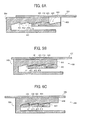
- FIGS. 6A-6C show operations of the upper-side detention device 400 as illustrated in FIGS. 5A and 5B , of which FIG. 6A is an end view showing a state in which the front case member covers the first rear case member; FIG. 6B is an end view showing the first combination position; and FIG. 6C is an end view showing the second combination position.
- FIG. 6A is an end view showing a state in which the front case member covers the first rear case member
- FIG. 6B is an end view showing the first combination position
- FIG. 6C is an end view showing the second combination position.
- the first peak 421 of the front-side detention step 420 crosses the second peak 414 of the rear-side detention step 410 and comes in the second recess 413 of the rear-side detention step 410 (see FIG. 6B ).
- the second peak 414 of the rear-side detention step 410 crosses the first peak 421 of the front-side detention step 420 and comes in the first recess 422 of the front-side detention step 420.
- the first peak 421 of the front-side detention step 420 and the second peak 414 of the rear-side detention step 410 engage each other, so that moving in an opposite direction (rightward move) by the first rear case member 200 and the front case member 300 is prevented.
- the member forming the upper-side detention device 400 is deformed elastically and returns to an original shape after the completion of crossing over.
- the first rear case member 200 and the front case member 300 are held in the assembled state being the first combination position in which the impact detector can be shipped.
- moving of the first weight 120 is prevented by stoppers 391, 392 (see FIG. 9A ) disposed in the right-side weight path 140 and the left-side weight path 150.
- the upper-side detention device 400 functions in the following manner (see FIGS. 6B and 6C ). Specifically, the first peak 421 and the second peak 423 of the front-side detention step 420 cross over the first peak 412 and the second peak 414 of the rear-side detention step 410 and enter the first recess 411 and the second recess 413 of the rear-side detention step 410, respectively.
- first peak 412 and the second peak 414 of the rear-side detention step 410 cross over the first peak 421 and the second peak 423 of the front-side detention step 420 and enter the first recess 422 and the second recess 424 of the front-side detention step 420, respectively.
- a member forming the upper-side detention device 400 is deformed elastically and returns to an original shape after the completion of crossing over.
- first peak 421 and the second peak 423 of the front-side detention step 420 and the first peak 412 and the second peak 414 of the rear-side detention step 410 engage each other, so that moving in an opposite direction (rightward move) by the first rear case member 200 and the front case member 300 is prevented.
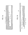
- FIGS. 7A and 7B show states of the lower-side detention device of the impact detector according to the first embodiment along Line D-D in FIG. 4 , of which FIG. 7A is an end view of the rear case member and FIG. 7B is an end view of the front case member.
- the lower-side detention device 500 includes a structure substantially identical to that of the upper-side detention device 400.
- the lower-side detention device 500 includes the rear-side detention step 510 formed at the first rear case member 200 and the front-side detention step 520 formed at the front case member 300.
- the rear-side detention step 510 includes two recessed portions, that is, a first recess 511 and a second recess 513; and two peak portions, that is, a first peak 512 and a second peak 514.
- the recesses and the peaks are alternately formed with a same pitch 'p'.
- the first peak 512 and the second peak 514 each are a right-angled triangle with a downward peak and a downward slope. Peaks are arc-shaped.
- the impact detector 100 includes the first peak 512 having a height h4 higher than a height h5 of the second peak 514 (h4>h5).
- a tilt angle ⁇ 4 of the first peak 512 is greater than a tilt angle ⁇ 5 of the second peak 514 ( ⁇ 4> ⁇ 5).
- ⁇ 4 is set to 24 degrees and 05 is set to 20 degrees.
- the front-side detention step 520 includes two peak portions, that is, a first peak 521 and a second peak 523; and two recessed portions, that is, a first recess 522 and a second recess 524.
- the recesses and the peaks are alternately formed with the same pitch 'p' as that of the rear-side detention step 510.
- the first peak 521 and the second peak 523 each are a right-angled triangle with an upward peak and an upward slope contrary to the rear-side detention step 510. Peaks are arc-shaped.
- the first peak 521 and the second peak 523 have a same height h6 and the first peak 521 and the second peak 523 have a same tilt angle ⁇ 6. In the present example, ⁇ 6 is set to 24 degrees.
- FIGS. 8A to 8C show operations of the lower-side detention device 500 as illustrated in FIGS. 7A and 7B , of which FIG. 8A is an end view showing a state in which the front case member covers the first rear case member; FIG. 8B is an end view showing the first combination position thereof; and FIG. 8C is an end view showing the second combination position thereof. Specifically, in the first combination position (see FIG. 8B ) from the state in which the front case member 300 just covers the first rear case member 200 (see FIG.
- the first peak 521 of the front-side detention step 520 crosses over the second peak 514 of the rear-side detention step 510 and comes in the second recess 513 of the rear-side detention step 510.
- the second peak 514 of the rear-side detention step 510 crosses over the first peak 521 of the front-side detention step 520 and comes in the first recess 522 of the front-side detention step 520.
- the first peak 521 of the front-side detention step 520 and the second peak 514 of the rear-side detention step 510 engage each other, so that moving in an opposite direction (rightward move) by the front case member 300 relative to the first rear case member 200 is prevented.
- a member forming the upper-side detention device 400 is deformed elastically and returns to an original shape after the completion of crossing over.
- the first rear case member 200 and the front case member 300 are held in the assembled state being the first combination position in which the impact detector can be shipped.
- the member forming the upper-side detention device 400 is deformed elastically and returns to an original shape after the completion of crossing over.
- the lower-side detention device 500 functions in the following manner (see FIG. 8C ). Specifically, the first peak 521 and the second peak 523 of the front-side detention step 520 cross over the first peak 512 and the second peak 514 of the rear-side detention step 510 and come into the first recess 511 and the second recess 513 of the rear-side detention step 510, respectively.
- the first peak 512 and the second peak 514 of the rear-side detention step 510 cross over the first peak 521 and the second peak 523 of the front-side detention step 520 and enter the first recess 522 and the second recess 524 of the front-side detention step 520, respectively. Then, the first peak 521 and the second peak 523 of the front-side detention step 520 and the first peak 512 and the second peak 514 of the rear-side detention step 510 engage each other, so that moving in an opposite direction (rightward move) by the front case member 300 relative to the first rear case member 200 is prevented.
- the resistive force when the first rear case member 200 and the front case member 300 move from the first combination position to the second combination position is greater than that when the first rear case member 200 and the front case member 300 move from the state in which the first rear case member 200 and the front case member 300 are simply engaged, to the first combination position.
- it is prevented to erroneously set the impact detector 140 to the second combination position in the assembly of the impact detector 100.
- This structural concept is applied to a case of assembling the second impact detector 1100 that employs the second rear case member 1200.
- the upper-side detention device 400 and the lower-side detection device 500 simultaneously function when slidably moving the front case member 300 relative to the first rear case member 200.
- the upper-side detention device 400 and the lower-side detention device 500 are preferably disposed at the same position in the width direction of the first rear case member 200 and the front case member 300.
- shapes and numbers of the peaks and the recesses of the upper-side detention device 400 and the lower-side detention device 500 may be appropriately selected without being limited to the examples described herein.
- the present embodiment discloses a structure in which the angles of the peaks are formed differently; however, the angles thereof may be identically formed and instead, a surface of the recess opposite the peak may be coated with a low-friction member or may be subjected to low-friction processing only in the second combination position.
- the structure is not limited to one using the peaks and recesses in combination, and another structure such as a non-return structure formed of pins and elastic members may also be used.
- the impact detector 100 or 1100 is configured such that the first rear case member 200 or the second rear case member 1200 combined with the front case member 300 are movable from an engaging state at a start of assembly to the first combination position (with a resistive force F1) after the completion of the assembly, and further movable from the first combination position to the second combination position (wit a resistive force F2).
- the resistive forces F1 and F2 sequentially increase.
- the present embodiment includes a third combination position (with a resistive force F3), in which the detected impact is stored.
- the present embodiment includes a fourth position (with a resistive force F4), in which the impact detector is disassembled.
- the resistive force F3 in which the detected impact is stored is between F1 and F2, and the resistive force F4 in the disassembled state is preferably the same as that of F3.
- the first rear case member 200 and the front case member 300 are relatively movable as a whole.
- a part of either the first rear case member 200 or the second rear case member 1200 and the front case member 300 may be formed as a movable part which can be replaced with another part, so that the movable part can be moved to the other part in the assembly process.
- the detention device as described above may be disposed between the movable part and the other part.
- the impact detectors 100, 1100 according to the first embodiment further includes a switching means which prevents the first weight 120 and the second weight 130 from moving from the initial position 120S and the initial position 130S, respectively, in the first combination position.
- FIGS. 9A to 9B each show a moving range of the weight of the impact detector according to the first embodiment, in which FIG. 9A is a plan view showing the first combination position and FIG. 9B is a plan view showing the second combination position.
- the examples in FIGS. 9A and 9B employ the first rear case member 200; however, even though the second rear case member 1200 is used, the switching means exerts the same function.
- the impact detector 100 employs, as switching means, stoppers 391, 392, and 393 disposed on the front case member 300.
- the stoppers 391, 392 formed on the front case member 300 are positioned in the right-side weight path 140 and the left-side weight path 150, and the stopper 393 is positioned in the proximal weight path 160 and the distal weight path 170.
- the first weight 120 does not move from the initial position 120S to the right-side detection position 120R or the left-side detection position 120L.
- the second weight 130 does not move from the initial position 130S to the proximal detection position 130F or the distal detection position 130B.
- the stoppers 391, 392, and 393 are away from each of the right-side weight path 140, the left-side weight path 150, the proximal weight path 160, and the distal weight path 170.
- the impact detector 100 is brought into a state detecting the impact or force due to the turnover in the front-back direction or in the lateral direction.
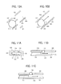
- FIGS. 10 to 12 are schematic views illustrating examples of other switching means.
- the structure to move the switching means to the first combination position or the second combination position is the same as described above, and therefore, detailed description thereof is omitted.
- FIGS. 10A and 10B show a case in which a part of the front case member 300 is formed as a movable portion, not shown, of a weight 610 relative to the rest of the front case member 300, and regulating members 621, 622 to prevent the move of the weight 610 are formed at the movable portion.
- the regulating members 621, 622 become a part of protruded members 631, 632 built to form a weight path 630 as illustrated in FIG.
- the regulating members 621, 622 are so positioned as to narrow the weight path 630. In such a state, moving of the weight 610 is prevented.
- the protruded member 631 represented by a solid line is disposed at the first rear case member 200 and the protruded member 632 represented by a broken line and the regulating members 621, 622 are formed at the front case member 300.
- the moving part is slid to turn into the second combination position, and the regulating members 621, 622 are moved to be integrated with the protruded portions 631, 632 as illustrated in FIG. 9B .
- the weight 610 can move in the weight path 630.
- the movable portion is formed on the front case member 300, thereby creating a regulating part.
- the regulating part can be disposed on the first rear case member 200.
- the regulating parts are disposed at both sides of the weight path 630.
- the weight path 630 may be formed with only one regulating part.
- FIGS. 11A to 11C show a case in which a part of the front case member 300 is formed as a movable portion, not shown, of a weight 710 relative to the rest of the front case member 300, and a regulating member 720 to prevent the move of the weight 710 is formed at the movable portion.
- the regulating member 720 is disposed at a position narrowing a weight path 730, so that the move of the weight 710 is prevented.
- the movable portion formed on the front case member 300 is moved to turn into the second combination position, and a regulating part 720 is moved, via a not-shown link, to a position as illustrated in FIG. 11C .
- the weight 730 can move in the weight path 730.
- the first rear case member 200 and the front case member 300 define the weight path 730, and each of the first rear case member 200 and the front case member 300 includes a rail 731 and a rail 732, respectively.
- the weight path 730 is formed between protruded members 733 and 734 built on the first rear case member 200 and the front case member 300, respectively.
- the regulating part 720 is formed on the front case member 300; however, alternatively, the regulating part may be formed on the first rear case member 200 and a part of the front case member 300 may be defined as the movable portion. Further, the rails 731, 732 disposed on the first rear case member 200 and the front case member 300 are configured to move integrally.
- FIG. 12 an example as illustrated in FIG. 12 is applied to a case including a sensor 800 to detect an impact due to a fall by detecting the fall of a weight 810.
- the weight 810 is held between blade springs 821, 822, of which leading ends approach each other downwardly. Due to the impact of the fall, the weight 810 expands the blade springs 821, 822 as illustrated by a broken line in FIG. 12 , and the thus- fallen weight 810 detects the impact.
- a part of the front case member 300 defined as a movable portion is slidably moved, so that pins 830 are laterally moved.
- the pins 830 are positioned at the solid line positions, and, even when the weight is given a force from the impact, the blade spring 821 is prevented from deforming. As a result, the weight 810 does not fall.
- the front case member 300 is slid leftward from the state in which the front case member 300 covers the first rear case member 200 or the second rear case member 1200, and the front case member 300 with the first rear case member 200 or with the second rear case member 1200 are positioned to the first combination position.
- the impact detector 100 does not sense the impact yet.
- the impact detector 100 or 1100 is attached to a vertical wall of the package and the front case member 300 is slid leftward, so that the first rear case member 200 or the second rear case member 1200 and the front case member 300 is set to the second combination position for sensing the impact.
- the top plate 310 of the front case member 300 includes an arc-shaped pressing portion 380, which the finger is hung on to slide the front case member 300 leftward in the figure.
- a bottom plate 210 of the first rear case member 200 and the second rear case member 1200 includes an arrow-shape hole 280 observable from the arc-shaped pressing portion 380 when the first rear case member 200 or the second rear case member 1200 and the front case member 300 are set to the second combination position.
- first rear case member 200 the second rear case member 1200, and the front case member 300 will be described.
- FIGS. 13A and 13B each show the first rear case member of the impact detector, of which FIG. 13A shows a plan view and FIG. 13B shows a bottom view thereof.
- FIGS. 14A and 14B each show the first rear case member of the impact detector, of which FIG. 14A shows a perspective view of the same and FIG. 14B shows a perspective view seen from another direction.
- FIGS. 15A and 15B each show the second rear case member of the impact detector according to the first embodiment, of which FIG. 15A shows a plan view and FIG. 15B shows a bottom view thereof.
- FIGS. 16A and 16B each show the second rear case member of the impact detector, of which FIG.
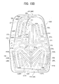
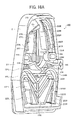
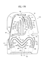
- FIGS. 17 and 18 each show the front case of the impact detector, of which FIG. 17A shows a plan view and FIG. 17B shows a bottom view thereof.
- FIGS. 18A and 18B each show the front case of the impact detector, of which FIG. 18A shows a perspective view of the same and FIG. 18B shows a perspective view seen from another direction.
- the first rear case member 200 includes a plate-shaped bottom plate 210 and walls 211, 212, and 213 surrounding a periphery of the bottom plate 210. Inside the walls 211, 212, and 213, there are provided partition walls 214R and 214L separating the lateral direction sensor section 180 and the front-back direction sensor section 190.
- the second rear case member 1200 also includes the walls 211, 212, and 213, the lateral direction sensor section 180, the front-back direction sensor section 190, and the partition walls 214R and 214L.
- the front case member 300 includes a plate-shaped top plate 310 and a wall 311 built along a partial outline of the top plate 310 (see the right side in FIG. 17A and the left side in FIG. 17B ).
- the top plate 310 includes two protruded portions 312 and 313.
- the top plate 310 includes a wall 314 to segment the lateral direction sensor section 180 from the front-back direction sensor section 190 and to support the second weight 130 in the proximal detection position 130F.
- first rear case member 200 the second rear case member 1200, and the front case member 300 each forming the lateral direction sensor section 180 will be described, with the first rear case member 200 described first.
- the lateral direction sensor section 180 includes, between the first rear case member 200 and the front case member 300, the right-side weight path 140, through which the first weight 120 moves due to the rightward falling, and the left-side weight path 150 through which the first weight 120 moves due to the leftward falling.
- the impact detector 100 falls rightward from the initial standing state and returns to the initial standing state, the first weight 120 moves from the initial position 120S to the right-side detection position 120R via the right-side weight path 140, which can be observed from the front case member 300.
- the first weight 120 moves from the initial position 120S to the left-side detection position 120L via the left-side weight path 150, which can be observed from the front case member 300.
- the bottom plate 210 of the first rear case member 200 forming the lateral direction sensor section 180 includes guide projections 221R, 221L and guide projections 222R, 222L which form the right-side weight path 140 and the left-side weight path 150.
- suffixes R and L mean 'right' and 'left.
- the guide projection 221R shows a right-side guide projection.
- the guide projections 221R, 221L are configured to have an interval narrowing downward and connected at a bottom, arc-shaped connecting portion 221C.
- the angle formed between each of the guide projections 221R, 221L and a horizontal line is 45 degrees.
- the initial position 120S of the first weight 120 is defined at the lowest portion of the guide projections 221R, 221L.
- the first weight 120 is positioned at the initial position 120S in the initial state in which the impact is not detected.
- the guide projections 222R, 222L are formed outside below the guide projections 221R, 221L. The first weight 120 which has moved due to the falling in the lateral direction is held between the right-side detection position 120R or the left-side detection position 120L and a wall 211 (see FIGS. 9A and 9B ).
- rails 223R, 224R, 223L, and 224L to guide the first weight 120 to the right-side weight path 140 and the left-side weight path 150 while reducing the moving resistance are formed to the bottom plate 210.
- Cross-sections of the rails 223R, 224R, 223L, and 224L each are formed as a semicircle so that the contact resistance with the first weight 120 is reduced.
- the rails 223R, 224R, 223L, and 224L are connected via a connection rail 229 disposed vertically.
- stepped portions 225R, 226R, 225L, and 226L to prevent the first weight 120 held at the right-side detection position 120R or the left-side detection position 120L from moving backward are formed continuously from the rails 223R, 224R, 223L, and 224L.
- a contact piece 227 is disposed above the initial position 120S.
- the contact piece 227 contacts the first weight 120 to prevent it from moving to the detection position 120R or 120L.
- the contact piece 227 includes a projection 227a formed at the left below the contact piece 227.
- the projection 227a prevents a malfunction of the first weight 120 due to its jumping by contacting the first weight 120.
- a recess 227b is formed at the right below the contact piece 227.
- the recess 227b receives the stopper 391 when the front case member 300 comes into the second combination position (see FIG. 9B ). When the stopper 391 enters into the recess 227b, it is configured such that the click feeling is generated.
- the second rear case member 1200 is constructed substantially similarly to the first rear case member 200 except that the right-side weight path 140 and the left-side weight path 150 are angled at a 60-degree angle relative to the horizontal direction. Accordingly, the difference of the second rear case member 1200 from the first rear case member 200 will be described. As illustrated in FIGS. 15 and 16 , the second rear case member 1200 is configured such that guide projections 1221R, 1221L are disposed angled at 60 degrees relative to the horizontal line when the second impact detector 1100 is disposed on the package. The guide projections 1221R, 1221L are disposed such that the interval therebetween is narrowed downward. The initial position 120S of the first weight 120 is defined by the bottom part of the guide projections 1221R, 1221L.
- rails 1228R, 1228L to reduce the moving resistance of the first weight 120 are disposed above the guide projections 1221R, 1221L.
- the guide projections 1221R, 1221L are joined at the bottom end.
- a rail 1229 which extends downward from a joint between the rails 224R, 224L and crosses over a joint between the rails 1228R, 1228L.
- the front case 300 is used in common by both the impact detectors 100 and 1100. Further, rails 323R, 324R, 323L, and 323L to guide the first weight 120 along the right-side weight path 140 and the left-side weight path 150 serving as a resistance reducer to reduce the moving resistance of the first weight 120 are formed on the top plate 310 of the front case member 300.
- the rails 323R, 324R, 323L, and 323L are connected by arc-shaped members 323C and 324C, respectively.
- the rails 323R and 323L and the arc-shaped portion 323C integrally serve as a second resistance reducer.
- rails 329R and 329L are disposed, as a resistance reducer, below the arc-shaped portion 323C so as to form a downward convex portion.
- the rails 329R and 329L are connected by an arc-shaped portion 329C, thereby forming a first resistance reducer.
- cross-sections of the rails 323R, 324R, 323L, and 323L, the arc-shaped members 323C and 324C, the rails 329R and 329L, and the arc-shaped portion 329C each are formed as a semicircle, so that the constant resistance is reduced.
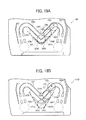
- FIGS. 19A and 19B each show a contacting state between the rails of the front case and the weight, of which FIG. 19A shows a schematic view using the first rear case member, and FIG. 19B shows a schematic view using the second rear case member.
- FIG. 20 is a schematic view using the second rear case member of the impact detector showing a contacting state between the rails of the front case and the weight.
- the rails 329R and 329L are positioned at the same positions as those of the guide projections 221R, 221L of the first rear case member 200 and are angled at 45 degrees relative to the horizontal line.
- the rails 323R and 323L are positioned parallel to the rails 329R and 329L. The interval between the rails 323R and 323L and the rails 329R and 329L is set to smaller than the diameter of the first weight 120.
- FIG. 19A shows the first weight 120 while moving from 120a, 120b to 120c, each shown by a broken line.
- the first weight 120 does not get hung up on any of the slanted rails. Then, the first weight 120 smoothly moves along the rail 323R.
- the in the first embodiment an example using the rails is described as a resistance reducer.
- small convex members with a width smaller than that of the rail are disposed regularly, so that another type of resistance reducer may be created.
- FIG. 19B shows the first weight 120 while moving from 120a, 120b to 120C, each shown by a broken line.
- the first weight 120 contacts the arc-shaped portion 323C and the arc-shaped portion 329C at a position 120a, contacts the rail 323R, the rail 324R, and the rail 329R at a position 120b, and contacts the rail 323R and the rail 324R at a position 120c.
- the first weight 120 does not get hung on any of the slanted rails. Accordingly, the first weight 120. smoothly moves along the rail 323R.
- a radius r1 of the arc-shaped portion 329C is greater than a radius r2 of the arc-shaped portion 323C.
- the resistance when the first weight 120 moves from the initial position 120S via the guide projections 1221R, 1221L is reduced.
- the radius r1 of the arc-shaped portion 329C is shortened (see line m in FIG. 20 showing an arc-shaped portion when the radius is set to r0) the moving resistance of the first weight 120 increases.
- the height of the rails 323R and 323L and the arc-shaped portion 323C, the rail 324R and 324L and the arc-shaped portion 324C, and the rails 329R and 329L and the arc-shaped portion 329C is in a range not contacting the first rear case member 200 or the second rear case member 1200 when front case member 300 is slidably constructed with the first rear case member 200 or the second rear case member 1200.
- the top plate 310 of the front case member 300 includes stepped portions 325R, 326R, 327R, 328R, 325L, 326L, 327L, and 328L to prevent the first weight 120 held at the right and left detection positions 120R and 120L from moving backward.
- the stoppers 391, 392 to prevent the first weight 120 from moving when the first rear case member 200 and the front case member 300 are brought to the first combination position, are disposed in a protruding manner above the initial position 120S.
- the stoppers 391, 392 disposed at the right-side weight path 140 and the left-side weight path 150 prevent the first weight 120 held at the initial position 120S from moving to the detection positions 120R, 120L (see FIG. 6A ).
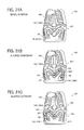
- FIGS. 21A-21C are a schematic view illustrating a state of detecting the impact in the lateral direction when the impact detector employs the first rear case member.
- the impact detector 100 falls rightward more than a predetermined angle from the directly standing state (see FIG. 21A )
- the first weight 120 moves along the right-side weight path 140 guided by the rail 323R, 324R, and the arc-shaped members 323C and 324C and reaches a top position 140T of the right-side weight path 140 (see FIGS. 17 and 18 ).
- the impact detector 100 is set back, the first weight 120 moves to the detection position 120R (see FIG. 21B ).
- the first weight 120 is prevented from moving backward by the stepped portions 225R, 226R of the first rear case member 200 and by the stepped portions 325R, 326R, 327R, and 328R of the front case member 300 and does not return to the right-side weight path 140.
- the first weight 120 moves along the left-side weight path 150 guided by the rails 323L, 324L, and the arc-shaped members 323C and 324C so as to reach a top position 150T of the left-side weight path 150 (see FIG. 21C ). Then, when the impact detector 100 is set back, the first weight 120 moves to the left-side detection position 120L (see FIG. 21C ).
- the first weight 120 is prevented from moving backward by the stepped portions 225L, 226L of the first rear case member 200 and by the stepped portions 325L, 326L, 327L, and 328L of the front case member 300 and does not return via the left-side weight path 150.
- FIGS. 22A-C is a schematic view illustrating a state of detecting the impact in the lateral direction when the impact detector employs the second rear case member according to the first embodiment.
- the first weight 120 moves along the right-side weight path 140 guided by the arc-shaped portion 329C, the rails 329R, 323R, 324R, the arc-shaped portion 323C, 324C to reach the top position 140T of the right-side weight path 140.
- the impact detector 1100 is set back, the first weight 120 moves to the detection position 120R (see FIG. 22B ).
- the first weight 120 is prevented from moving backward by the stepped portions 225R, 226R of the second rear case member 1200 and the stepped portions 325R, 326R, 327R, and 328R of the front case member 300 and does not return via the right-side weight path 140.
- the first weight 120 moves along the left-side weight path 150 guided by the arc-shaped portion 329C, rail 329L, 323L, 324L, the arc-shaped portions 323C and 324C to reach the top position 150T of the left-side weight path 150. Then, when the impact detector 1100 is set back, the first weight 120 moves to the left-side detection position 120L (see FIG. 22C ).
- the first weight 120 is prevented from moving backward by the stepped portions 225L, 226L of the second rear case member 1200 and by the stepped portions 325L, 326L, 327L, and 328L of the front case member 300 and does not return via the left-side weight path 150.
- the front-back direction sensor section 190 includes, between the first rear case member 200 or the second rear case member 1200 and the front case member 300, the proximal weight path 160 and the distal weight path 170.
- the second weight 130 moves along the proximal weight path 160 due to the falling toward front and moves along the distal weight path 170 moves due to the falling toward backside.
- the first impact detector 100 or the second impact detector 1100 falls toward front from the vertically standing state and then returns to the standing state, the second weight 130 moves from the initial position 130S to the proximal detection position 130F via the proximal weight path 160, which can be observed from the side of the front case member 300.
- the second weight 130 moves from the initial position 130S to the distal detection position 130B via the distal weight path 170 and can be observed from the front case member 300.
- the first rear case member 200 and the second rear case member 1200 each forming the front-back direction sensor section 190 include the same structure, the first rear case member 200 is selected as an example and will be described. Among the first rear case member 200, a portion constructing the front-back direction sensor section 190 will be described (see FIGS. 13 and 14 ).
- the bottom plate 210 of the first rear case member 200 forming the front-back direction sensor section 190 includes guide projections 231R and 231L.
- An arc-shaped hold wall 215, with an upward opening to hold the second weight 130 at the initial position 130S is formed below the guide projections 231R and 231L.
- the guide projections 231R and 231L are formed with a slightly increasing interval therebetween in the vertical direction.
- the initial position 130S of the second weight 130 is defined below the guide projections 231R and 231L (see FIG. 9A ) and the second weight 130 is positioned at the initial position 130S in the initial state not sensing any impact or force.
- the guide projection 231L includes a malfunction preventing projection 231a to prevent the second weight 130 from jumping due to a vertical impact and moving along the distal weight path 170.
- a projection 238 is disposed at a position symmetrical with respect to the malfunction preventing projection 231a so as to prevent the second weight 130 from moving toward the proximal weight path 160 erroneously.
- the partition walls 214R and 214L to hold the second weight 130 which has moved due to the front-back falling are formed outside below the guide projections 231R and 231L.
- hold projections 235R and 235L are formed on the bottom plate 210 at positions corresponding to the proximal detection position 130F and the distal detection position 130B. The hold projections 235R and 235L prevent fluctuation of the second weight 130.
- the hold projections 235R and 235L each sandwich the second weight 130 along with the front case member 300.
- rails 232R and 232L to guide the second weight 130 while reducing the moving resistance of the second weight 130 are disposed in an interior of the guide projections 231R and 231L.
- rails 233R, 233L, 234R, and 234L to guide the second weight 130 are disposed at outer right and left positions.
- the rails 233R, 233L, 234R, and 234L include stepped portions 241R, 241L, 242R, and 242L to prevent the second weight 130 held at the distal detection position 130B from moving backward.
- a curved wall 236 to guide the second weight 130 to move from the initial position 130S to the distal detection position 130B via the distal weight path 170.
- a gap is formed between an upper end of the curved wall 236 and the front case member 300 and the second weight 130 moving along the proximal weight path 160 passes through the gap.
- a stepped portion 237 to prevent the backward moving of the second weight 130 held at the distal detection position 130B, is disposed at a beginning of a curved portion 170a in the distal weight path 170.
- the top plate 310 of the front case member 300 includes guide projections 331R and 331L to guide the second weight 130 along the proximal weight path 160 and the distal weight path 170.
- rails 333R and 333L to guide the second weight 130 while reducing the moving resistance of the second weight 130 are disposed between the guide projections 331R and 331L.
- an arc-shaped projection 334 to hold the second weight 130 at the initial position 130S is disposed below the rails 333R and 333L.
- Cross-sections of the rails 333R and 333L each are formed into a semicircle so that the contact resistance with the first weight 120 is reduced.
- the top plate 310 includes a projection 347 to prevent the second weight 130 positioned at the initial position 130S from moving in the second combination position is formed at a position symmetrical with respect to the stopper 393(see FIG. 9A ).
- the top plate 310 includes a curved wall 336 to guide the second weight 130 moving from the initial position 130S via the proximal weight path 160 to the proximal detection position 130F.
- a gap is formed between an upper end of the curved wall 336 and the front case member 200, and the second weight 130 moving along the distal weight path 170 passes through the gap.
- Rails 337 and 338 to guide the second weight 130 are disposed at positions corresponding to the proximal weight path 160 of the top plate 310.
- Stepped portions 339 and 340 to prevent the second weight 130 from moving backward are each disposed at a lower end of the rails 337 and 338, respectively. Further, at lower steps of the stepped portions 339 and 340, claws 341 and 342 to prevent the backward moving of the second weight 130 are disposed.
- claws 343, 344, 345, and 356 to prevent the backward moving of the second weight 130 from the distal detection position 130B are disposed at positions corresponding to the distal weight path 170 of the top plate 310.
- FIGS. 23A and 23B each show a cross-sectional view of the first impact detector 100 along the Line B-B in FIG. 3B , of which FIG. 23A shows a cross-sectional view when the first impact detector 100 falls in the distal direction, and FIG. 23B shows a cross-sectional view when the first impact detector falls in the proximal direction.
- FIGS. 24A to 24C each show a schematic view when the first impact detector 100 detects an impact in the front-back direction. As illustrated in FIG.
- the second weight 130 slides on the rails 232R and 232L disposed between the guide projections 231R and 231L of the first rear case member 200 and moves up to a peak portion 170T (see FIG. 24B ).
- the second weight 130 slides on the rails 233L and 234L formed between the guide projection 321L and the wall 211, and moves up to the distal detection position 130B. In this case, the second weight 130 crosses over the stepped portion 237.
- the second weight 130 slides on the rails 232R and 232L formed between the guide projections 331R and 331L of the front case member 300 and moves up to a peak portion 160T of the proximal weight path 160 (see FIG. 24C ).
- the second weight 130 passes claws 343 and 344 formed between the guide projection 331R and the wall 211 via the curved wall 336 and is positioned at the proximal detection position 130F.
- the second weight 130 is prevented from moving backward by stepped portions 241R and 242 of the first rear case member 200 and claws 343 and 344 of the front case member 300, and does not move backward along the proximal weight path 160.
- the first impact detector 100 and the second impact detector 1100 may detect the impact or force due to the turnover in the front-back direction or in the lateral direction.
- assembly of the product is easier because of a not-complicated structure.
- the impact detector 100 does not come into the impact-detectable state. As a result, handling becomes easier.
- the front case member 300 according to the first embodiment used for the impact detector 100 or 1100 can be used in common for two types of impact detectors detecting two different inclinations. Even used with either of the impact detectors, the front case member 300 can reduce the moving resistance of the weight.
- the impact detectors 100 and 1100 each including the lateral direction sensor section 180 and the front-back direction sensor section 190 are described as example; however, the impact detector may employ only the lateral direction sensor section. Further, the impact detector may employ other types of sensor sections capable of detecting the impact or force in other directions performed by the lateral direction sensor section and the front-back direction sensor section.
- FIG. 25 is a perspective view illustrating a package including a impact detector.
- the first impact detector 100 or the second impact detector 1100 according to the first embodiment is attached to a side 910 of a cardboard box 900 as a detection target using a double-sided adhesive tape and a label 930 is attached thereon.
- a combination of the front case member 300 and selected one of the first rear case member 200 and the second rear case member 1200 enables to select the angle for detecting the impact.
- the impact detector 100 or 1100 may either be attached on the cardboard box 900 or may be fitted in a recess formed on the side 910 of the cardboard box 900 to be fixed on the vertical surface of the shipped product.
- the impact detector 100 or 1100 is attached on the cardboard box 900, if the cardboard box 900 falls and receives an impact or force, one may remove the impact detector and remove the front case, so as to return the weight to an initial state (falsification).
- the label 930 serves as a sealing member.
- the attached surface of the label 930 should preferably include such an adhesive that a part on the attached surface remains, if removed from the cardboard box 900. Thus, whether or not the seal has been removed for falsification can be checked.
- FIG. 26 shows a front view illustrating an example of a label
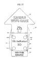
- FIG. 27 shows a front view of the label attached on the front case member of the impact detector.
- the label 930 is formed to have an arrow shape with a tip of the arrow directed upward.
- FIG. 26 also includes a linear side view of the label 930 seen from the bottom, and a linear longitudinal side view of the label 930 seen from the right side.
- the label 930 includes three portions, that is, a tip portion 931, a central portion 935, and a bottom portion 932. Background of the tip portion 931 and the bottom portion 932 is black as illustrated by hatched lines rising from left to right, and letters are shown in white.
- the tip portion 931 includes letters of "HANDLE WITH CARE" in white and the bottom portion 932 includes letters "If tilt detected, indicating" in white and a red letter "RED”.
- the central portion 935 includes displays 933B, 933F, 933L, and 933R, from which the weight can be observed corresponding to positions of the observation windows of the front case member.
- the display 933B is formed at a position corresponding to the observation window 303, from which the weight moving to the distal detection position 130B is observed.
- the display 933F is formed at a position corresponding to the observation window 304, from which the weight moving to the proximal detection position 130F is observed.
- the display 933L is formed at a position corresponding to the observation window 301, from which the weight moving to the left-side detection position 120L is observed.
- the display 933R is formed at a position corresponding to the observation window 302, from which the weight moving to the right-side detection position 120R is observed.
- the color of the central portion 935 should preferably be a complementary color of the color of the weight displayed at the displays 933B, 933F, 933L, and 933R.
- the central portion 935 is set to yellow (see FIG. 26 , in which the central portion 935 is shown by hatched lines falling from left to right).
- the color of the weight is set to bluish-purple, which is a complementary color of yellow, so that the visibility of the weight is improved.
- the central portion 935 includes letters of "Tilt indicator 3D" represented in black.
- positioning holes 934 are formed in a boundary between the tip portion 931 and the central portion 935. As illustrated in FIG. 27 , the positioning holes 934 are provided, for example, so as to easily position the positioning holes 934 at convex portions extending on the surface of the front case member 300. The positioning holes 934 are not necessary if the position to attach the label 930 is conceivable.
- FIG. 29 shows a front view of a modified label
- FIG. 30 shows a front view of another modified label.
- displays 943B, 943F, 943L, and 943R are positioned above those of the label 930 in FIG. 28 .
- displays 953B, 953F, 953L, and 953R are positioned above those of the label 940 in FIG. 29 .
Landscapes
- Physics & Mathematics (AREA)
- General Physics & Mathematics (AREA)
- Engineering & Computer Science (AREA)
- Radar, Positioning & Navigation (AREA)
- Remote Sensing (AREA)
- Mechanical Engineering (AREA)
- Analytical Chemistry (AREA)
- Chemical & Material Sciences (AREA)
- Life Sciences & Earth Sciences (AREA)
- Biochemistry (AREA)
- General Health & Medical Sciences (AREA)
- Immunology (AREA)
- Pathology (AREA)
- Health & Medical Sciences (AREA)
- Studio Devices (AREA)
- Telephone Set Structure (AREA)
Abstract
The present invention provides a case for an impact detector (100, 1100) having a weight (120, 130) to move from an initial position when a detection target of the impact detector (100, 1100) inclines more than a predetermined angle, includes a front case (300); a first rear case (200) to be covered by the front case (300), including a guide member set at a first inclination angle, through which the weight moves; a second rear case (1200) to be covered by the front case (300), including a guide member set at a second inclination angle different from the first inclination angle, through which the weight moves; and a resistance reducer to reduce moving resistance of the weight, including a first resistance reducer (329R, 329L, 329C) disposed at a same angle as the guide member of the first rear case (200) and a second resistance reducer (323R, 323L, 323C) disposed apart from the first resistance reducer. The front case (300) is used in common for both the first rear case (200) and the second rear case (1200) and selectively for each of the first rear case and the second rear case; the weight contacts the second resistance reducer when the front case (300) is attached to the first rear case (200); and the weight contacts the first resistance reducer and the second resistance reducer when the front case (300) is attached to the second rear case (1200).
Description
- The present invention relates to a case for an impact detector to detect that a product has received an impact or a forth, and further relates to an impact detector using the case, and a package employing the impact detector.
- When a product such as a precision device is transported, there is an occasion where the product is damaged due to handling in the transportation. If the impact or the force given to the product is below a certain level, a damage preventive measure taken during packaging may prevent damage to the product. However, when unexpected impact or force has been applied to the product due to erroneous or rough handling, damage to the product cannot be prevented completely.
- If the exterior package is greatly damaged due to the impact, damage to the internal product can be found before arriving at a customer's site or a store. However, there is a case in which an internal product only is damaged even though there is no change in the external appearance. In such a case, the damage to the product is found after the customer has received the product and unpacked it, which may cause claims from the customer and a loss of reliability to the vendor. Then, an approach has been taken, in which a package is provided with an impact detector and the impact applied to the package is detected.
-
JP-2009-156726-A - The impact detector as disclosed in
JP-2009-156726-A - Such an impact detector includes at least two case members and includes a weight disposed in the case members. Then, each case needs to be formed corresponding to the slant to detect at least one of the cases.
- Considering the above point, the present invention provides a commonly useable case member for the impact detector which detects at least two types of tilt angles, in which weights can move smoothly even when detecting either of the tilt angles.
- More specifically, the present invention provides a case for a impact detector, including: a front case; a weight to move from an initial position when a detection target of the impact detector inclines more than a predetermined angle; a first rear case to be covered by the front case, including a guide member set at a first inclination angle, through which the weight moves; a second rear case to be covered by the front case, including a guide member set at a second inclination angle different from the first inclination angle, through which the weight moves; and a resistance reducer to reduce moving resistance of the weight. In the optimal case for the impact detector, the front case is used in common for the first and second rear cases; the resistance reducer includes a first resistance reducer disposed at a same angle with the guide member of the first rear case and a second resistance reducer disposed apart from the first resistance reducer; the weight contacts the second resistance reducer when the front case is attached to the first rear case member; and the weight contacts the first and second reducers when the front case is attached to the second rear case member.
- These and other objects, features, and advantages of the present invention will become apparent upon consideration of the following description of the preferred embodiments of the present invention when taken in conjunction with the accompanying drawings.
-
-
FIG. 1 is an exploded perspective view of an impact detector related to a first embodiment of the present invention when a first rear case member is used; -
FIG. 2 is an exploded perspective view of an impact detector related to the first embodiment of the present invention when a second rear case member is used; -
FIGS. 3A and 3B each show an assembly of the impact detector according to the first embodiment, in whichFIG. 3A is a plan view showing a state in which the front case member covers the second rear case member, andFIG. 3B is a plan view showing a first combination position by the front case member and the second rear case member; -
FIG. 4 is a schematic cross-sectional view illustrating an assembled state of the impact detector according to the first embodiment along Line A-A inFIG. 3A ; - FTGS. 5A and 5B are an upper-side detention device of the impact detector according to the first embodiment along Line C-C in
FIG. 4 , of whichFIG. 5A is an end view of the rear case member andFIG. 5B is an end view of the front case member; -
FIGS. 6A to 6C show operations of the upper-side detention device as illustrated inFIGS. 5A and 5B , of whichFIG. 6A is an end view showing a state in which the front case member covers the first rear case member;FIG. 6B is an end view showing the first combination position; andFIG. 6C is an end view showing the second combination position; -
FIGS. 7A and 7B show states of the lower-side detention device of the impact detector according to the first embodiment along Line D-D inFIG. 4 , of whichFIG. 7A is an end view of the rear case member andFIG. 7B is an end view of the front case member; -
FIGS. 8A to 8C show operations of the lower-side detention device as illustrated inFIGS. 7A and 7B , of whichFIG. 8A is an end view showing a state in which the front case member covers the first rear case member;FIG. 8B is an end view showing the first combination position thereof; andFIG. 8C is an end view showing the second combination position thereof; -
FIGS. 9A and9B show a moving range of the weight according to a switching means of the impact detector according to the first embodiment, of whichFIG. 9A is a plan view showing the first combination position, andFIG. 9B is a plan view showing the second combination position; -
FIGS. 10A and 10B are schematic views showing other switching means; - FTGS. 11A to 11C are schematic views showing other switching means;
-
FIG. 12 is a schematic view showing another switching means; -
FIGS. 13A and13B each show the first rear case member of the impact detector, of whichFIG. 13A shows a plan view andFIG. 13B shows a bottom view thereof; -
FIGS. 14A and14B each show the first rear case member of the impact detector, of whichFIG. 14A shows a perspective view of the same andFIG. 14B shows a perspective view seen from another direction; -
FIGS. 15A and15B each show the second rear case member of the impact detector according to the first embodiment, of whichFIG. 15A shows a plan view andFIG. 15B shows a bottom view thereof; -
FIGS. 16A and16B each show the second rear case member of the impact detector, of whichFIG. 15A shows a perspective view of the same andFIG. 15B shows a perspective view seen from another direction; -
FIGS. 17A and17B each show the front case of the impact detector, of whichFIG. 17A shows a plan view andFIG. 17B shows a bottom view thereof; -
FIGS. 18A and18B each show the front case of the impact detector, of whichFIG. 18A shows a perspective view of the same andFIG. 18B shows a perspective view seen from another direction; -
FIGS. 19A and 19B each show a contacting state between the rails of the front case and the weight, of whichFIG. 19A shows a schematic view using the first rear case member, andFIG. 19B shows a schematic view using the second rear case member; -
FIG. 20 is a schematic view using the second rear case member of the impact detector showing a contacting state between the rails of the front case and the weight; -
FIGS. 21A to 21C are views each illustrating a state of detecting the impact in the lateral direction when the impact detector employs the first rear case member; -
FIGS. 22A to 22C are views each illustrating a state of detecting the impact in the lateral direction when the impact detector employs the second rear case member; -
FIGS. 23A and 23B each show a cross-sectional view of the first impact detector along the Line B-B inFIG. 3B , of whichFIG. 23A shows a cross-sectional view when the first impact detector falls in the distal direction, andFIG. 23B shows a cross-sectional view when the first impact detector falls in the proximal direction; -
FIGS. 24A to 24C each show a schematic view when the first impact detector detects an impact in the front-back direction; -
FIG. 25 is a perspective view illustrating a package including a impact detector according to a second embodiment; -
FIG. 26 shows a front view of the label with bottom and side views attached on the front case member; -
FIG. 27 shows a front view of the label attached on the front case member; -
FIG. 28 shows a front view illustrating another example of a label; -
FIG. 29 shows a front view illustrating a modified example of a label; and -
FIG. 30 shows a front view illustrating a modified example of a label. - Hereinafter, a schematic configuration of an impact detector related to a first embodiment will be described.
- In the first embodiment, two types of impact detectors are provided: one is formed of a
front case member 300, a common case member, and a firstrear case member 200; and the other formed of the commonfront case member 300 and a secondrear case member 1200. The two types of impact detectors each come into a detecting state at a different tilt angle. Specifically, afirst impact detector 100 is formed by combining thefront case member 300 with the firstrear case member 200, and asecond impact detector 1100 is formed by combining thefront case member 300 with the secondrear case member 1200. Thefirst impact detector 100 comes into the detecting state when inclined by 45 degrees, and thesecond impact detector 1100 comes into the detecting state when inclined by 60 degrees. In addition, theimpact detectors front case member 300 as a common case member used for bothimpact detectors -
FIG. 1 is an exploded perspective view of an impact detector related to the first embodiment of the present invention when the first rear case member is used. Theimpact detector 100 includes a lateraldirection sensor section 180 detecting that a drop or tilt has occurred in the horizontal direction in thecase 110; and a front-backdirection sensor section 190 detecting that a drop or tilt has occurred in the front-back direction in thecase 110. - In addition, the
first impact detector 100 further includes two discoidal weights including afirst weight 120 and asecond weight 130 in thecase 110. Thefirst weight 120 is disposed at the lateraldirection sensor section 180 and thesecond weight 130 at the front-backdirection sensor section 190. - The lateral
direction sensor section 180 includes a right-side weight path 140 and a left-side weight path 150 to guide thefirst weight 120. The right-side weight path 140 guides thefirst weight 120 from aninitial position 120S to a right-side detection position 120R. The right-side weight path 150 guides thefirst weight 120 from theinitial position 120S to a left-side detection position 120L. The right-side weight path 140 and the left-side weight path 150 are formed such that thefirst weight 120 moves when thefirst impact detector 100 is tilted by 45 degrees. - The front-back
direction sensor section 190 includes aproximal weight path 160 and adistal weight path 170 to guide thesecond weight 130. Theproximal weight path 160 guides thesecond weight 130 from aninitial position 130S to aproximal detection position 130F. In addition, theproximal weight path 160 guides thesecond weight 130 from theinitial position 130S to adistal detection position 130B. - The
first impact detector 100 includes the front-backdirection sensor section 190 disposed above the lateraldirection sensor section 180. In place of the front-backdirection sensor section 190, various other forms of weight can be employed by combining any of the various forms. For example, the one in which the weight held by an elastic member falls by being separated from the elastic member due to the impact may be used. Further, thefirst impact detector 100 may include only the lateraldirection sensor section 180. - The first
rear case member 200 is a mold of synthetic resins such as opaque ABS resins of black color, for example, and includes projections of various shapes to form, in combination with thefront case member 300, the right-side weight path 140, the left-side weight path 150, theproximal weight path 160, and thedistal weight path 170. Further, thefront case member 300 is a mold of synthetic resins such as transparent ABS resins, and includes projections of various shapes to form, in combination with the firstrear case member 200, the right-side weight path 140, the left-side weight path 150, theproximal weight path 160, and thedistal weight path 170. - In addition, the
front case member 300 includes atop plate 310 that includesobservation windows weights observation windows observation windows - The
first weight 120 and thesecond weight 130 are preferably formed of a material with a comparatively high specific gravity. Even with a smaller thickness and diameter, the mass may be adjusted and theimpact detector 100 can be made compact. Preferred materials for thefirst weight 120 and thesecond weight 130 are corrosion-resistant stainless steel and aluminum. The periphery of the weight should be chamfered so that the weight can move smoothly in thecase 110. Further, it is preferred that each weight is colored with a different color or has a different label for an easier discrimination. - Next, the
second impact detector 1100 will be described. -
FIG. 2 is an exploded perspective view of an impact detector according to the first embodiment when the second rear case member is used. Thesecond impact detector 1100 is formed by combining the secondrear case member 1200 and thefront case member 300. The samefront case member 300 used in thefirst impact detector 100 can be used. In the secondrear case member 1200, the right-side weight path 140 and the left-side weight path 150 are configured such that thefirst weight 120 moves when thesecond impact detector 1100 is tilted by 60 degrees. As a result, as will be described later, the part that forms the right-side weight path 140 and the left-side weight path 150 is different from the firstrear case member 200. - Next, how to assemble the impact detector will be described. Because the
first impact detector 100 and thesecond impact detector 1100 are assembled in a similar manner, assembly of only one of the firstrear case member 200 and the secondrear case member 1200 is described, it being understood that the description applies equally to both case members. -
FIGS. 3A and 3B each show an assembling operation of the impact detector according to the first embodiment, in whichFIG. 3A is a plan view showing a state in which the front case member covers the second rear case member, andFIG. 3B is a plan view showing a first combination position by the front case member and the second rear case member. - As illustrated in
FIG. 3 , thecase 110 is assembled such that, first, the secondrear case member 1200 and thefront case member 300 are engaged, thefront case member 300 is slid leftward relative to the secondrear case member 1200, and the secondrear case member 1200 and thefront case member 300 are laterally moved so as to be assembled together. When assembled, an upper-side detention device 400 is created at an upper end where the secondrear case member 1200 and thefront case member 300 are closely contacted. Similarly, a lower-side detention device 500 is created at a bottom end where the secondrear case member 1200 and thefront case member 300 are closely contacted. As will be described later, the upper-side detention device 400 and the lower-side detection device 500 prevent the secondrear case member 1200 and thefront case member 300 from returning from the first combination position or from the assembled state and prevent the secondrear case member 1200 from coming off from thefront case member 300. The upper-side detention device 400 and the lower-side detection device 500 prevent the secondrear case member 1200 and thefront case member 300 from returning from a second combination position for impact sensing to the first combination position and prevent incapable state of the impact or the tilt. Herein, in the second combination position, theimpact detector 100 is disposed on a package or the like and comes into an impact sensing state. The assembled structure is the same for thefirst impact detector 100 using the firstrear case member 200. - In general, considering the fact that a user touches a central, left end portion of the
front case member 300 when sliding thefront case member 300 leftward, theimpact detectors side detention device 400 and the lower-side detention device 500 disposed at the both upper and lower sides. With this structure, while preventing the tilt between the firstrear case member 200 and thefront case member 300 in the sliding movement, thefront case member 300 can be moved smoothly. -
FIG. 4 is a schematic cross-sectional view illustrating an assembled state of the impact detector according to the first embodiment along Line A-A inFIG. 3 . The upper-side detention device 400 is configured such that a rear-side detention step 410 formed on the firstrear case member 200 is slid in and engaged with a front-side detention step 420 formed on thefront case member 300. In addition, the lower-side detention device 500 is configured such that a rear-side detention step 510 formed on the firstrear case member 200 is slid in and engaged with a front-side detention step 520 formed on thefront case member 300. - With the first
rear case member 200 covered by thefront case member 300, thefront case member 300 is slid leftward so that the upper-side detention device 400 and the lower-side detention device 500 come to the first combination position from a state in which the firstrear case member 200 is not engaged with thefront case member 300, and from the first combination position to the second combination position. - In the first combination position, the first
rear case member 200 and thefront case member 300 are ready for shipping, are in a state incapable of sensing the impact, and are prevented from disengaging from each other. In the second combination position, theimpact detector 100 is attached to the packing and the like and is capable of sensing the impact. - A click is felt each time the upper-
side detention device 400 and the lower-side detention device 500 moves on to the first combination position where thefront case member 300 is shifted leftward over the firstrear case member 200 from a state simply covering the firstrear case member 200; and when moving to the second combination position. The upper-side detention device 400 and the lower-side detection device 500 prevent the firstrear case member 200 and thefront case member 300 from moving inversely. In addition, resistance of the upper-side detention device 400 when the firstrear case member 200 and thefront case member 300 moves from the first combination position to the second combination position is greater than when the firstrear case member 200 and thefront case member 300 moves to the first combination position from a state in which thefront case member 300 simply covers the firstrear case member 200. - First, the upper-
side detention device 400 will be described. -
FIGS. 5A and 5B are an upper-side detention device of the impact detector according to the first embodiment along Line C-C inFIG. 4 seen from the arrow direction, of whichFIG. 5A is an end view of the rear case member andFIG. 5B is an end view of the front case member. The upper-side detention device 400 includes the rear-side detention step 410 formed at the firstrear case member 200 and the front-side detention step 420 formed at thefront case member 300. The rear-side detention step 410 includes two recessed portions, that is, afirst recess 411 and asecond recess 413; and two peak portions, that is, afirst peak 412 and asecond peak 414. The recesses and the peaks are alternatingly formed with a same pitch 'p'. Thefirst peak 412 and thesecond peak 414 each are a right-angled triangle with a peak and a slope downward. The peaks may include an arc shape. Theimpact detector 100 according to the present embodiment includes thefirst peak 412 having a height h1 higher than a height h2 of the second peak 414 (h1>h2). In addition, a tilt angle θ1 of thefirst peak 412 is greater than atilt angle 02 of the second peak 414 (θ1>θ2). In this example, θ1 is set to 24 degrees and θ2 is set to 20 degrees. - The front-
side detention step 420 includes two peak portions, that is, afirst peak 421 and asecond peak 423; and two recessed portions, that is, afirst recess 422 and asecond recess 424. The recesses and the peaks are alternately formed with the same pitch 'p' as that of the rear-side detention step 410. Thefirst peak 421 and thesecond peak 423 each are a right-angled triangle with an upward peak and an upward slope contrary to the rear-side detention step 410. Peaks are arc-shaped. In thepresent impact detector 100, thefirst peak 421 and thesecond peak 423 have a same height h3 and thefirst peak 421 and thesecond peak 423 have a same tilt angle θ3. In this example, θ3 is set to 24 degrees. - When the
front case member 300 covers the firstrear case member 200 and thefront case member 300 slides leftward, the present upper-side detention device 400 function as illustrated inFIGS. 6A-6C. FIGS. 6A to 6C show operations of the upper-side detention device 400 as illustrated inFIGS. 5A and 5B , of whichFIG. 6A is an end view showing a state in which the front case member covers the first rear case member;FIG. 6B is an end view showing the first combination position; andFIG. 6C is an end view showing the second combination position. Specifically, in the first combination position (seeFIG. 6B ) from the state in which thefront case member 300 covers the firstrear case member 200 and thefront case member 300 is slid slightly (seeFIG. 6A ), thefirst peak 421 of the front-side detention step 420 crosses thesecond peak 414 of the rear-side detention step 410 and comes in thesecond recess 413 of the rear-side detention step 410 (seeFIG. 6B ). Similarly, thesecond peak 414 of the rear-side detention step 410 crosses thefirst peak 421 of the front-side detention step 420 and comes in thefirst recess 422 of the front-side detention step 420. Then, thefirst peak 421 of the front-side detention step 420 and thesecond peak 414 of the rear-side detention step 410 engage each other, so that moving in an opposite direction (rightward move) by the firstrear case member 200 and thefront case member 300 is prevented. In addition, when each peak crosses the other peak, the member forming the upper-side detention device 400 is deformed elastically and returns to an original shape after the completion of crossing over. - In addition, in the move to the first combination position, each time the
second peak 414 of the rear-side detention step 410 crosses over thesecond peak 423 of the front-side detention step 420 to enter thefirst recess 422 and similarly, each time thefirst peak 421 of the front-side detention step 420 crosses over thesecond peak 414 of the rear-side detention step 410 to enter thesecond recess 413 of the rear-side detention step 410, a click is felt as well as a resistive force. - Accordingly, the first
rear case member 200 and thefront case member 300 are held in the assembled state being the first combination position in which the impact detector can be shipped. In the lateraldirection sensor section 180, moving of thefirst weight 120 is prevented bystoppers 391, 392 (seeFIG. 9A ) disposed in the right-side weight path 140 and the left-side weight path 150. - Further, when the first
rear case member 200 and thefront case member 300 comes to the second combination position from the first combination position, the upper-side detention device 400 functions in the following manner (seeFIGS. 6B and 6C ). Specifically, thefirst peak 421 and thesecond peak 423 of the front-side detention step 420 cross over thefirst peak 412 and thesecond peak 414 of the rear-side detention step 410 and enter thefirst recess 411 and thesecond recess 413 of the rear-side detention step 410, respectively. Similarly, thefirst peak 412 and thesecond peak 414 of the rear-side detention step 410 cross over thefirst peak 421 and thesecond peak 423 of the front-side detention step 420 and enter thefirst recess 422 and thesecond recess 424 of the front-side detention step 420, respectively. When each peak crosses over the other peak, a member forming the upper-side detention device 400 is deformed elastically and returns to an original shape after the completion of crossing over. - Then, the
first peak 421 and thesecond peak 423 of the front-side detention step 420 and thefirst peak 412 and thesecond peak 414 of the rear-side detention step 410 engage each other, so that moving in an opposite direction (rightward move) by the firstrear case member 200 and thefront case member 300 is prevented. - In the moving to the second combination position, two
peaks side detention step 410 cross over the twopeaks side detention step 420 and enter the tworecesses first peak 421 and thesecond peak 423 of the front-side detention step 420 cross over thefirst peak 412 and thesecond peak 414 of the rear-side detention step 410 and enter thefirst recess 411 and thesecond recess 413 of the rear-side detention step 410, respectively. This time, the 'click' feeling is given as well as the resistive force. Because the height h1 of thefirst peak 412 of the rear-side detention step 410 that thefirst peak 421 of the front-side detention step 420 has to cross over is higher than the height h2 of thesecond peak 414, the resistive force increases. - Next, the lower-
side detention device 500 will be described. -
FIGS. 7A and 7B show states of the lower-side detention device of the impact detector according to the first embodiment along Line D-D inFIG. 4 , of whichFIG. 7A is an end view of the rear case member andFIG. 7B is an end view of the front case member. The lower-side detention device 500 includes a structure substantially identical to that of the upper-side detention device 400. - The lower-
side detention device 500 includes the rear-side detention step 510 formed at the firstrear case member 200 and the front-side detention step 520 formed at thefront case member 300. The rear-side detention step 510 includes two recessed portions, that is, afirst recess 511 and asecond recess 513; and two peak portions, that is, afirst peak 512 and asecond peak 514. The recesses and the peaks are alternately formed with a same pitch 'p'. Thefirst peak 512 and thesecond peak 514 each are a right-angled triangle with a downward peak and a downward slope. Peaks are arc-shaped. Theimpact detector 100 according to the present embodiment includes thefirst peak 512 having a height h4 higher than a height h5 of the second peak 514 (h4>h5). In addition, a tilt angle θ4 of thefirst peak 512 is greater than a tilt angle θ5 of the second peak 514 (θ4>θ5). In this example, θ4 is set to 24 degrees and 05 is set to 20 degrees. - In addition, the front-
side detention step 520 includes two peak portions, that is, afirst peak 521 and asecond peak 523; and two recessed portions, that is, afirst recess 522 and asecond recess 524. The recesses and the peaks are alternately formed with the same pitch 'p' as that of the rear-side detention step 510. Thefirst peak 521 and thesecond peak 523 each are a right-angled triangle with an upward peak and an upward slope contrary to the rear-side detention step 510. Peaks are arc-shaped. In thepresent impact detector 100, thefirst peak 521 and thesecond peak 523 have a same height h6 and thefirst peak 521 and thesecond peak 523 have a same tilt angle θ6. In the present example, θ6 is set to 24 degrees. - When the
front case member 300 covers the firstrear case member 200 and thefront case member 300 slides leftward, the present lower-side detention device 500 functions in the following manner.FIGS. 8A to 8C show operations of the lower-side detention device 500 as illustrated inFIGS. 7A and 7B , of whichFIG. 8A is an end view showing a state in which the front case member covers the first rear case member;FIG. 8B is an end view showing the first combination position thereof; andFIG. 8C is an end view showing the second combination position thereof. Specifically, in the first combination position (seeFIG. 8B ) from the state in which thefront case member 300 just covers the first rear case member 200 (seeFIG. 8A ), thefirst peak 521 of the front-side detention step 520 crosses over thesecond peak 514 of the rear-side detention step 510 and comes in thesecond recess 513 of the rear-side detention step 510. Similarly, thesecond peak 514 of the rear-side detention step 510 crosses over thefirst peak 521 of the front-side detention step 520 and comes in thefirst recess 522 of the front-side detention step 520. Then, thefirst peak 521 of the front-side detention step 520 and thesecond peak 514 of the rear-side detention step 510 engage each other, so that moving in an opposite direction (rightward move) by thefront case member 300 relative to the firstrear case member 200 is prevented. When each peak crosses over the other peak, a member forming the upper-side detention device 400 is deformed elastically and returns to an original shape after the completion of crossing over. - In addition, in the move to the first combination position, each time the
second peak 514 of the rear-side detention step 510 crosses over thesecond peak 523 of the front-side detention step 520 to enter thefirst recess 522, and similarly, each time thefirst peak 521 of the front-side detention step 520 crosses over thesecond peak 514 of the rear-side detention step 510 to enter thesecond recess 513 of the rear-side detention step 510, a click is felt as well as a resistive force. - Accordingly, the first
rear case member 200 and thefront case member 300 are held in the assembled state being the first combination position in which the impact detector can be shipped. When each peak crosses over the other peak, the member forming the upper-side detention device 400 is deformed elastically and returns to an original shape after the completion of crossing over. - Further, when the first
rear case member 200 and thefront case member 300 come into the second combination position from the first combination position, the lower-side detention device 500 functions in the following manner (seeFIG. 8C ). Specifically, thefirst peak 521 and thesecond peak 523 of the front-side detention step 520 cross over thefirst peak 512 and thesecond peak 514 of the rear-side detention step 510 and come into thefirst recess 511 and thesecond recess 513 of the rear-side detention step 510, respectively. - Similarly, the
first peak 512 and thesecond peak 514 of the rear-side detention step 510 cross over thefirst peak 521 and thesecond peak 523 of the front-side detention step 520 and enter thefirst recess 522 and thesecond recess 524 of the front-side detention step 520, respectively. Then, thefirst peak 521 and thesecond peak 523 of the front-side detention step 520 and thefirst peak 512 and thesecond peak 514 of the rear-side detention step 510 engage each other, so that moving in an opposite direction (rightward move) by thefront case member 300 relative to the firstrear case member 200 is prevented. - In the moving to the second combination position, two
peaks side detention step 510 cross over the twopeaks side detention step 520 and enter the tworecesses first peak 521 and thesecond peak 523 of the front-side detention step 520 cross over thefirst peak 512 and thesecond peak 514 of the rear-side detention step 510 and enter thefirst recess 511 and thesecond recess 513 of the rear-side detention step 510, respectively. At this time, the click as well as the resistive force are felt. In this case, because the height h4 of thefirst peak 521 of the rear-side detention step 520 that thefirst peak 521 of the front-side detention step 520 has to cross over is higher than the height h5 of thesecond peak 514, the resistive force increases. - As described above, the resistive force when the first
rear case member 200 and thefront case member 300 move from the first combination position to the second combination position is greater than that when the firstrear case member 200 and thefront case member 300 move from the state in which the firstrear case member 200 and thefront case member 300 are simply engaged, to the first combination position. As a result, it is prevented to erroneously set theimpact detector 140 to the second combination position in the assembly of theimpact detector 100. This structural concept is applied to a case of assembling thesecond impact detector 1100 that employs the secondrear case member 1200. - The upper-
side detention device 400 and the lower-side detection device 500 simultaneously function when slidably moving thefront case member 300 relative to the firstrear case member 200. To make the relative movement of the firstrear case member 200 and thefront case member 300 smoother, the upper-side detention device 400 and the lower-side detention device 500 are preferably disposed at the same position in the width direction of the firstrear case member 200 and thefront case member 300. - In addition, shapes and numbers of the peaks and the recesses of the upper-
side detention device 400 and the lower-side detention device 500 may be appropriately selected without being limited to the examples described herein. Further, although the present embodiment discloses a structure in which the angles of the peaks are formed differently; however, the angles thereof may be identically formed and instead, a surface of the recess opposite the peak may be coated with a low-friction member or may be subjected to low-friction processing only in the second combination position. Further, the structure is not limited to one using the peaks and recesses in combination, and another structure such as a non-return structure formed of pins and elastic members may also be used. - Further, the
impact detector rear case member 200 or the secondrear case member 1200 combined with thefront case member 300 are movable from an engaging state at a start of assembly to the first combination position (with a resistive force F1) after the completion of the assembly, and further movable from the first combination position to the second combination position (wit a resistive force F2). The resistive forces F1 and F2 sequentially increase. In addition, the present embodiment includes a third combination position (with a resistive force F3), in which the detected impact is stored. Furthermore, the present embodiment includes a fourth position (with a resistive force F4), in which the impact detector is disassembled. The resistive force F3 in which the detected impact is stored is between F1 and F2, and the resistive force F4 in the disassembled state is preferably the same as that of F3. - Further, in the
impact detectors rear case member 200 and thefront case member 300 are relatively movable as a whole. However, a part of either the firstrear case member 200 or the secondrear case member 1200 and thefront case member 300 may be formed as a movable part which can be replaced with another part, so that the movable part can be moved to the other part in the assembly process. Between the movable part and the other part, the detention device as described above may be disposed. - The
impact detectors first weight 120 and thesecond weight 130 from moving from theinitial position 120S and theinitial position 130S, respectively, in the first combination position.FIGS. 9A to 9B each show a moving range of the weight of the impact detector according to the first embodiment, in whichFIG. 9A is a plan view showing the first combination position andFIG. 9B is a plan view showing the second combination position. The examples inFIGS. 9A and9B employ the firstrear case member 200; however, even though the secondrear case member 1200 is used, the switching means exerts the same function. - The
impact detector 100 employs, as switching means,stoppers front case member 300. As illustrated inFIG. 9A , in a shipping state, that is, when the firstrear case member 200 and thefront case member 300 are positioned in the first combination position, thestoppers front case member 300 are positioned in the right-side weight path 140 and the left-side weight path 150, and thestopper 393 is positioned in theproximal weight path 160 and thedistal weight path 170. As a result, thefirst weight 120 does not move from theinitial position 120S to the right-side detection position 120R or the left-side detection position 120L. In addition, thesecond weight 130 does not move from theinitial position 130S to theproximal detection position 130F or thedistal detection position 130B. - As illustrated in
FIG. 9B , in an impact detecting state, that is, when the firstrear case member 200 and thefront case member 300 are positioned in the second combination position, thestoppers side weight path 140, the left-side weight path 150, theproximal weight path 160, and thedistal weight path 170. As a result, theimpact detector 100 is brought into a state detecting the impact or force due to the turnover in the front-back direction or in the lateral direction. - However, the switching means is not limited to the aforementioned structure.
FIGS. 10 to 12 are schematic views illustrating examples of other switching means. The structure to move the switching means to the first combination position or the second combination position is the same as described above, and therefore, detailed description thereof is omitted.FIGS. 10A and 10B show a case in which a part of thefront case member 300 is formed as a movable portion, not shown, of aweight 610 relative to the rest of thefront case member 300, and regulatingmembers weight 610 are formed at the movable portion. In the present example, the regulatingmembers members weight path 630 as illustrated inFIG. 10B . Then, in the first combination position as illustrated inFIG. 10A , the regulatingmembers weight path 630. In such a state, moving of theweight 610 is prevented. In this example, the protrudedmember 631 represented by a solid line is disposed at the firstrear case member 200 and the protrudedmember 632 represented by a broken line and the regulatingmembers front case member 300. - Then, the moving part is slid to turn into the second combination position, and the regulating
members portions FIG. 9B . In this state, theweight 610 can move in theweight path 630. - In this example, the movable portion is formed on the
front case member 300, thereby creating a regulating part. However, by forming a part of thefront case member 300 as the movable portion, the regulating part can be disposed on the firstrear case member 200. Further, the regulating parts are disposed at both sides of theweight path 630. However, by disposing the regulating part at one of the regulatingmembers weight path 630 may be formed with only one regulating part. -
FIGS. 11A to 11C show a case in which a part of thefront case member 300 is formed as a movable portion, not shown, of aweight 710 relative to the rest of thefront case member 300, and a regulatingmember 720 to prevent the move of theweight 710 is formed at the movable portion. At the first combination position as illustrated inFIG. 11B , the regulatingmember 720 is disposed at a position narrowing aweight path 730, so that the move of theweight 710 is prevented. - Then, the movable portion formed on the
front case member 300 is moved to turn into the second combination position, and a regulatingpart 720 is moved, via a not-shown link, to a position as illustrated inFIG. 11C . In this state, theweight 730 can move in theweight path 730. The firstrear case member 200 and thefront case member 300 define theweight path 730, and each of the firstrear case member 200 and thefront case member 300 includes arail 731 and arail 732, respectively. In addition, theweight path 730 is formed between protrudedmembers rear case member 200 and thefront case member 300, respectively. - In this example, the regulating
part 720 is formed on thefront case member 300; however, alternatively, the regulating part may be formed on the firstrear case member 200 and a part of thefront case member 300 may be defined as the movable portion. Further, therails rear case member 200 and thefront case member 300 are configured to move integrally. - Furthermore, an example as illustrated in
FIG. 12 is applied to a case including a sensor 800 to detect an impact due to a fall by detecting the fall of aweight 810. In the sensor 800, theweight 810 is held between blade springs 821, 822, of which leading ends approach each other downwardly. Due to the impact of the fall, theweight 810 expands the blade springs 821, 822 as illustrated by a broken line inFIG. 12 , and the thus-fallenweight 810 detects the impact. In this example, as a switching means, a part of thefront case member 300 defined as a movable portion is slidably moved, so thatpins 830 are laterally moved. When the movable portion is set to the first combination position, thepins 830 are positioned at the solid line positions, and, even when the weight is given a force from the impact, theblade spring 821 is prevented from deforming. As a result, theweight 810 does not fall. - Then, when the movable portion is set to the second combination position, the
pins 830 move to a direction separating from the blade springs 821, 822 and theweight 810 falls due to the impact of the fall. - In addition, as the regulating member, various structures other than the ones described above may be used if appropriate.
- As described heretofore, when the
first impact detector 100 and thesecond impact detector 1100 are assembled and shipped as a commercial product, thefront case member 300 is slid leftward from the state in which thefront case member 300 covers the firstrear case member 200 or the secondrear case member 1200, and thefront case member 300 with the firstrear case member 200 or with the secondrear case member 1200 are positioned to the first combination position. In the shipped state, theimpact detector 100 does not sense the impact yet. Theimpact detector front case member 300 is slid leftward, so that the firstrear case member 200 or the secondrear case member 1200 and thefront case member 300 is set to the second combination position for sensing the impact. - The
top plate 310 of thefront case member 300 includes an arc-shapedpressing portion 380, which the finger is hung on to slide thefront case member 300 leftward in the figure. In addition, abottom plate 210 of the firstrear case member 200 and the secondrear case member 1200 includes an arrow-shape hole 280 observable from the arc-shapedpressing portion 380 when the firstrear case member 200 or the secondrear case member 1200 and thefront case member 300 are set to the second combination position. As a result, it is securely observed that thecase 110 is set to the second combination position in which the impact can be detected. - Next, details of the first
rear case member 200, the secondrear case member 1200, and thefront case member 300 will be described. - First, the first
rear case member 200 will be described.FIGS. 13A and13B each show the first rear case member of the impact detector, of whichFIG. 13A shows a plan view andFIG. 13B shows a bottom view thereof. Similarly,FIGS. 14A and14B each show the first rear case member of the impact detector, of whichFIG. 14A shows a perspective view of the same andFIG. 14B shows a perspective view seen from another direction.FIGS. 15A and15B each show the second rear case member of the impact detector according to the first embodiment, of whichFIG. 15A shows a plan view andFIG. 15B shows a bottom view thereof. Similarly,FIGS. 16A and16B each show the second rear case member of the impact detector, of whichFIG. 15A shows a perspective view of the same andFIG. 15B shows a perspective view seen from another direction.FIGS. 17 and18 each show the front case of the impact detector, of whichFIG. 17A shows a plan view andFIG. 17B shows a bottom view thereof. Similarly,FIGS. 18A and18B each show the front case of the impact detector, of whichFIG. 18A shows a perspective view of the same andFIG. 18B shows a perspective view seen from another direction. - As illustrated in
FIGS. 13 and14 , the firstrear case member 200 includes a plate-shapedbottom plate 210 andwalls bottom plate 210. Inside thewalls partition walls direction sensor section 180 and the front-backdirection sensor section 190. - On the other hand, as illustrated in
FIGS. 15A through 16B , the secondrear case member 1200 also includes thewalls direction sensor section 180, the front-backdirection sensor section 190, and thepartition walls - As illustrated in
FIGS. 17 and18 , thefront case member 300 includes a plate-shapedtop plate 310 and awall 311 built along a partial outline of the top plate 310 (see the right side inFIG. 17A and the left side inFIG. 17B ). In addition, thetop plate 310 includes two protrudedportions top plate 310 includes awall 314 to segment the lateraldirection sensor section 180 from the front-backdirection sensor section 190 and to support thesecond weight 130 in theproximal detection position 130F. - Hereinafter, the structure of the first
rear case member 200, the secondrear case member 1200, and thefront case member 300 each forming the lateraldirection sensor section 180 will be described, with the firstrear case member 200 described first. - The lateral
direction sensor section 180 includes, between the firstrear case member 200 and thefront case member 300, the right-side weight path 140, through which thefirst weight 120 moves due to the rightward falling, and the left-side weight path 150 through which thefirst weight 120 moves due to the leftward falling. When theimpact detector 100 falls rightward from the initial standing state and returns to the initial standing state, thefirst weight 120 moves from theinitial position 120S to the right-side detection position 120R via the right-side weight path 140, which can be observed from thefront case member 300. - Similarly, when the
impact detector 100 falls leftward from the initial standing state and returns to the initial standing state, thefirst weight 120 moves from theinitial position 120S to the left-side detection position 120L via the left-side weight path 150, which can be observed from thefront case member 300. - First, part of the first
rear case member 200 forming the lateraldirection sensor section 180 will be described (seeFIGS. 13 and14 ). - The
bottom plate 210 of the firstrear case member 200 forming the lateraldirection sensor section 180 includesguide projections projections side weight path 140 and the left-side weight path 150. Herein, suffixes R and L mean 'right' and 'left.' For example, theguide projection 221R shows a right-side guide projection. - The
guide projections portion 221C. In the first embodiment, the angle formed between each of theguide projections direction sensor section 180, thefirst weight 120 starts to move when theimpact detector 100 is slanted in the lateral direction by 45 degrees. Theinitial position 120S of thefirst weight 120 is defined at the lowest portion of theguide projections first weight 120 is positioned at theinitial position 120S in the initial state in which the impact is not detected. In addition, theguide projections guide projections first weight 120 which has moved due to the falling in the lateral direction is held between the right-side detection position 120R or the left-side detection position 120L and a wall 211 (seeFIGS. 9A and9B ). - Further, rails 223R, 224R, 223L, and 224L to guide the
first weight 120 to the right-side weight path 140 and the left-side weight path 150 while reducing the moving resistance are formed to thebottom plate 210. Cross-sections of therails first weight 120 is reduced. Therails connection rail 229 disposed vertically. Further, steppedportions first weight 120 held at the right-side detection position 120R or the left-side detection position 120L from moving backward are formed continuously from therails - Further, a
contact piece 227 is disposed above theinitial position 120S. When thefirst weight 120 held at theinitial position 120S jumps due to a slight impact, thecontact piece 227 contacts thefirst weight 120 to prevent it from moving to thedetection position FIG. 13A , thecontact piece 227 includes aprojection 227a formed at the left below thecontact piece 227. Theprojection 227a prevents a malfunction of thefirst weight 120 due to its jumping by contacting thefirst weight 120. On the other hand, arecess 227b is formed at the right below thecontact piece 227. Therecess 227b receives thestopper 391 when thefront case member 300 comes into the second combination position (seeFIG. 9B ). When thestopper 391 enters into therecess 227b, it is configured such that the click feeling is generated. - Next, the second
rear case member 1200 will be described (seeFIGS. 15A through 16B ). - The second
rear case member 1200 is constructed substantially similarly to the firstrear case member 200 except that the right-side weight path 140 and the left-side weight path 150 are angled at a 60-degree angle relative to the horizontal direction. Accordingly, the difference of the secondrear case member 1200 from the firstrear case member 200 will be described. As illustrated inFIGS. 15 and16 , the secondrear case member 1200 is configured such thatguide projections second impact detector 1100 is disposed on the package. Theguide projections initial position 120S of thefirst weight 120 is defined by the bottom part of theguide projections - In addition, rails 1228R, 1228L to reduce the moving resistance of the
first weight 120 are disposed above theguide projections guide projections rail 1229, which extends downward from a joint between therails rails - Next, a portion constructing the lateral
direction sensor section 180 in thefront case member 300 will be described (seeFIGS. 17A through 18B ). - The
front case 300 is used in common by both theimpact detectors first weight 120 along the right-side weight path 140 and the left-side weight path 150 serving as a resistance reducer to reduce the moving resistance of thefirst weight 120 are formed on thetop plate 310 of thefront case member 300. Therails members rails portion 323C integrally serve as a second resistance reducer. Further, rails 329R and 329L are disposed, as a resistance reducer, below the arc-shapedportion 323C so as to form a downward convex portion. Therails portion 329C, thereby forming a first resistance reducer. In addition, cross-sections of therails members rails portion 329C each are formed as a semicircle, so that the constant resistance is reduced. - A set of the
rails portion 323C as a second resistance reducer and a set of therails portion 329C as a first resistance reducer will be described.FIGS. 19A and 19B each show a contacting state between the rails of the front case and the weight, of whichFIG. 19A shows a schematic view using the first rear case member, andFIG. 19B shows a schematic view using the second rear case member. Similarly,FIG. 20 is a schematic view using the second rear case member of the impact detector showing a contacting state between the rails of the front case and the weight. - In the first embodiment, as illustrated in
FIG. 19A , when therails rear case member 200, therails guide projections rear case member 200 and are angled at 45 degrees relative to the horizontal line. In addition, therails rails rails rails first weight 120. - As illustrated in
FIG. 19A , in a state in which thefront case member 300 is combined with the firstrear case member 200, thefirst weight 120 moves along the rail 323 while contacting therails guide projection 221R. In this case, thefirst weight 120 contacts both therails FIG. 19A shows thefirst weight 120 while moving from 120a, 120b to 120c, each shown by a broken line. Thus, thefirst weight 120 does not get hung up on any of the slanted rails. Then, thefirst weight 120 smoothly moves along therail 323R. - It is to be noted that the in the first embodiment, an example using the rails is described as a resistance reducer. However, small convex members with a width smaller than that of the rail are disposed regularly, so that another type of resistance reducer may be created.
- In addition, as illustrated in
FIG. 19B , when thefront case member 300 is combined with the secondrear case member 1200, when thefirst weight 120 moves along therail 323R, thefirst weight 120 contacts the arc-shapedportion 323C, the arc-shapedportion 329C, therail 329R, therail 323R, and therail 324R, sequentially at two positions.FIG. 19B shows thefirst weight 120 while moving from 120a, 120b to 120C, each shown by a broken line. Specifically, thefirst weight 120 contacts the arc-shapedportion 323C and the arc-shapedportion 329C at aposition 120a, contacts therail 323R, therail 324R, and therail 329R at aposition 120b, and contacts therail 323R and therail 324R at aposition 120c. As a result, thefirst weight 120 does not get hung on any of the slanted rails. Accordingly, thefirst weight 120. smoothly moves along therail 323R. - In addition, in the first embodiment, as illustrated in
FIG. 20 , a radius r1 of the arc-shapedportion 329C is greater than a radius r2 of the arc-shapedportion 323C. As a result, the resistance when thefirst weight 120 moves from theinitial position 120S via theguide projections portion 329C is shortened (see line m inFIG. 20 showing an arc-shaped portion when the radius is set to r0) the moving resistance of thefirst weight 120 increases. This is because, when thefirst weight 120 moves along aguide projection 1221R, a contact length L1 of therail 329L when the radius of thefirst weight 120 is r0 perpendicular to the moving direction of thefirst weight 120 becomes longer than a length L2 when the radius offirst weight 120 is r1. - In addition, the height of the
rails portion 323C, therail portion 324C, and therails portion 329C is in a range not contacting the firstrear case member 200 or the secondrear case member 1200 whenfront case member 300 is slidably constructed with the firstrear case member 200 or the secondrear case member 1200. - Further, as illustrated in
FIGS. 17A through 18B , thetop plate 310 of thefront case member 300 includes steppedportions first weight 120 held at the right and leftdetection positions stoppers first weight 120 from moving when the firstrear case member 200 and thefront case member 300 are brought to the first combination position, are disposed in a protruding manner above theinitial position 120S. When the firstrear case member 200 and thefront case member 300 are positioned at the first combination position, thestoppers side weight path 140 and the left-side weight path 150 prevent thefirst weight 120 held at theinitial position 120S from moving to the detection positions 120R, 120L (seeFIG. 6A ). - Next, a portion constructing the lateral
direction sensor section 180 will be described. - First, an operation to detect falling in the lateral direction by the lateral
direction sensor section 180 of thefirst impact detector 100 will be described. -
FIGS. 21A-21C are a schematic view illustrating a state of detecting the impact in the lateral direction when the impact detector employs the first rear case member. When theimpact detector 100 falls rightward more than a predetermined angle from the directly standing state (seeFIG. 21A ), thefirst weight 120 moves along the right-side weight path 140 guided by therail members top position 140T of the right-side weight path 140 (seeFIGS. 17 and18 ). Then, when theimpact detector 100 is set back, thefirst weight 120 moves to thedetection position 120R (seeFIG. 21B ). In this state, thefirst weight 120 is prevented from moving backward by the steppedportions rear case member 200 and by the steppedportions front case member 300 and does not return to the right-side weight path 140. - Similarly, when the
impact detector 100 falls leftward more than a predetermined angle from the directly standing state (seeFIG. 21A ), thefirst weight 120 moves along the left-side weight path 150 guided by therails members top position 150T of the left-side weight path 150 (seeFIG. 21C ). Then, when theimpact detector 100 is set back, thefirst weight 120 moves to the left-side detection position 120L (seeFIG. 21C ). In this state, thefirst weight 120 is prevented from moving backward by the steppedportions rear case member 200 and by the steppedportions front case member 300 and does not return via the left-side weight path 150. - Next, an operation to detect falling in the lateral direction by the lateral
direction sensor section 180 of thesecond impact detector 1100 will be described. -
FIGS. 22A-C is a schematic view illustrating a state of detecting the impact in the lateral direction when the impact detector employs the second rear case member according to the first embodiment. When thesecond impact detector 1100 falls rightward more than a predetermined angle from the directly standing state (seeFIG. 22A ), thefirst weight 120 moves along the right-side weight path 140 guided by the arc-shapedportion 329C, therails portion top position 140T of the right-side weight path 140. Then, when theimpact detector 1100 is set back, thefirst weight 120 moves to thedetection position 120R (seeFIG. 22B ). In this state, thefirst weight 120 is prevented from moving backward by the steppedportions rear case member 1200 and the steppedportions front case member 300 and does not return via the right-side weight path 140. - Similarly, when the
impact detector 1100 falls leftward more than a predetermined angle from the directly standing state (seeFIG. 22A ), thefirst weight 120 moves along the left-side weight path 150 guided by the arc-shapedportion 329C,rail portions top position 150T of the left-side weight path 150. Then, when theimpact detector 1100 is set back, thefirst weight 120 moves to the left-side detection position 120L (seeFIG. 22C ). In this state, thefirst weight 120 is prevented from moving backward by the steppedportions rear case member 1200 and by the steppedportions front case member 300 and does not return via the left-side weight path 150. - Next, the front-back
direction sensor section 190 will be described. - The front-back
direction sensor section 190 includes, between the firstrear case member 200 or the secondrear case member 1200 and thefront case member 300, theproximal weight path 160 and thedistal weight path 170. Thesecond weight 130 moves along theproximal weight path 160 due to the falling toward front and moves along thedistal weight path 170 moves due to the falling toward backside. When thefirst impact detector 100 or thesecond impact detector 1100 falls toward front from the vertically standing state and then returns to the standing state, thesecond weight 130 moves from theinitial position 130S to theproximal detection position 130F via theproximal weight path 160, which can be observed from the side of thefront case member 300. - Similarly, when the
impact detector 100 falls backward from the standing posture and then returns to the standing posture, thesecond weight 130 moves from theinitial position 130S to thedistal detection position 130B via thedistal weight path 170 and can be observed from thefront case member 300. - In the first embodiment, because the first
rear case member 200 and the secondrear case member 1200 each forming the front-backdirection sensor section 190 include the same structure, the firstrear case member 200 is selected as an example and will be described. Among the firstrear case member 200, a portion constructing the front-backdirection sensor section 190 will be described (seeFIGS. 13 and14 ). Thebottom plate 210 of the firstrear case member 200 forming the front-backdirection sensor section 190 includesguide projections hold wall 215, with an upward opening to hold thesecond weight 130 at theinitial position 130S is formed below theguide projections - The
guide projections initial position 130S of thesecond weight 130 is defined below theguide projections FIG. 9A ) and thesecond weight 130 is positioned at theinitial position 130S in the initial state not sensing any impact or force. In addition, theguide projection 231L includes amalfunction preventing projection 231a to prevent thesecond weight 130 from jumping due to a vertical impact and moving along thedistal weight path 170. In addition, aprojection 238 is disposed at a position symmetrical with respect to themalfunction preventing projection 231a so as to prevent thesecond weight 130 from moving toward theproximal weight path 160 erroneously. - In addition, the
partition walls second weight 130 which has moved due to the front-back falling are formed outside below theguide projections projections bottom plate 210 at positions corresponding to theproximal detection position 130F and thedistal detection position 130B. Thehold projections second weight 130. Thehold projections second weight 130 along with thefront case member 300. - In addition, rails 232R and 232L to guide the
second weight 130 while reducing the moving resistance of thesecond weight 130 are disposed in an interior of theguide projections second weight 130 are disposed at outer right and left positions. Further, therails portions second weight 130 held at thedistal detection position 130B from moving backward. - In addition, above the
rails curved wall 236 to guide thesecond weight 130 to move from theinitial position 130S to thedistal detection position 130B via thedistal weight path 170. A gap is formed between an upper end of thecurved wall 236 and thefront case member 300 and thesecond weight 130 moving along theproximal weight path 160 passes through the gap. Further, a steppedportion 237, to prevent the backward moving of thesecond weight 130 held at thedistal detection position 130B, is disposed at a beginning of acurved portion 170a in thedistal weight path 170. - Next, a portion constructing the front-back
direction sensor section 190 among thefront case member 300 will be described (seeFIGS. 17 and18 ). - The
top plate 310 of thefront case member 300 includesguide projections second weight 130 along theproximal weight path 160 and thedistal weight path 170. In addition, rails 333R and 333L to guide thesecond weight 130 while reducing the moving resistance of thesecond weight 130 are disposed between theguide projections projection 334 to hold thesecond weight 130 at theinitial position 130S is disposed below therails rails first weight 120 is reduced. - In addition, the
top plate 310 includes aprojection 347 to prevent thesecond weight 130 positioned at theinitial position 130S from moving in the second combination position is formed at a position symmetrical with respect to the stopper 393(seeFIG. 9A ). - Further, the
top plate 310 includes acurved wall 336 to guide thesecond weight 130 moving from theinitial position 130S via theproximal weight path 160 to theproximal detection position 130F. A gap is formed between an upper end of thecurved wall 336 and thefront case member 200, and thesecond weight 130 moving along thedistal weight path 170 passes through the gap. -
Rails second weight 130 are disposed at positions corresponding to theproximal weight path 160 of thetop plate 310. Steppedportions second weight 130 from moving backward are each disposed at a lower end of therails portions claws second weight 130 are disposed. - Further,
claws second weight 130 from thedistal detection position 130B are disposed at positions corresponding to thedistal weight path 170 of thetop plate 310. - Next, an operation to detect falling in the front-back direction by the front-back
direction sensor section 190 of thefirst impact detector 100 and thesecond impact detector 1100 will be described. Because the operation of the front-backdirection sensor section 190 in the bothimpact detectors first impact detector 100 will be described. -
FIGS. 23A and 23B each show a cross-sectional view of thefirst impact detector 100 along the Line B-B inFIG. 3B , of whichFIG. 23A shows a cross-sectional view when thefirst impact detector 100 falls in the distal direction, andFIG. 23B shows a cross-sectional view when the first impact detector falls in the proximal direction.FIGS. 24A to 24C each show a schematic view when thefirst impact detector 100 detects an impact in the front-back direction. As illustrated inFIG. 23A , when theimpact detector 100 falls backward (that is, toward the first rear case member 200), thesecond weight 130 slides on therails guide projections rear case member 200 and moves up to apeak portion 170T (seeFIG. 24B ). Next, when theimpact detector 100 is brought to the standing state, thesecond weight 130 slides on therails wall 211, and moves up to thedistal detection position 130B. In this case, thesecond weight 130 crosses over the steppedportion 237. - In this state, moving backward of the
second weight 130 positioned at thedistal detection position 130B is prevented by steppedportions portions front case member 300, and theclaws second weight 130 does not move backward in the lateraldirection sensor section 180. - On the other hand, if the
impact detector 100 falls in the frontal direction (that is, toward the front case member 300), thesecond weight 130 slides on therails guide projections front case member 300 and moves up to apeak portion 160T of the proximal weight path 160 (seeFIG. 24C ). Next, when theimpact detector 100 is brought into a standing state, thesecond weight 130passes claws guide projection 331R and thewall 211 via thecurved wall 336 and is positioned at theproximal detection position 130F. In this state, thesecond weight 130 is prevented from moving backward by steppedportions 241R and 242 of the firstrear case member 200 andclaws front case member 300, and does not move backward along theproximal weight path 160. - As a result, the
first impact detector 100 and thesecond impact detector 1100 according to the first embodiment may detect the impact or force due to the turnover in the front-back direction or in the lateral direction. Further, according to theimpact detector impact detector impact detector 100, theimpact detector 100 does not come into the impact-detectable state. As a result, handling becomes easier. - In addition, the
front case member 300 according to the first embodiment used for theimpact detector front case member 300 can reduce the moving resistance of the weight. - In the first embodiment, the
impact detectors direction sensor section 180 and the front-backdirection sensor section 190 are described as example; however, the impact detector may employ only the lateral direction sensor section. Further, the impact detector may employ other types of sensor sections capable of detecting the impact or force in other directions performed by the lateral direction sensor section and the front-back direction sensor section. - Hereinafter, a package including the impact detector according to the first embodiment will be described as a second embodiment.
FIG. 25 is a perspective view illustrating a package including a impact detector. In the illustrated example, thefirst impact detector 100 or thesecond impact detector 1100 according to the first embodiment is attached to aside 910 of acardboard box 900 as a detection target using a double-sided adhesive tape and alabel 930 is attached thereon. In this case, a combination of thefront case member 300 and selected one of the firstrear case member 200 and the secondrear case member 1200 enables to select the angle for detecting the impact. Theimpact detector cardboard box 900 or may be fitted in a recess formed on theside 910 of thecardboard box 900 to be fixed on the vertical surface of the shipped product. When theimpact detector cardboard box 900, if thecardboard box 900 falls and receives an impact or force, one may remove the impact detector and remove the front case, so as to return the weight to an initial state (falsification). Thelabel 930 serves as a sealing member. The attached surface of thelabel 930 should preferably include such an adhesive that a part on the attached surface remains, if removed from thecardboard box 900. Thus, whether or not the seal has been removed for falsification can be checked. - Next, the
label 930 will be described. -
FIG. 26 shows a front view illustrating an example of a label; andFIG. 27 shows a front view of the label attached on the front case member of the impact detector. - As illustrated in
FIGS. 26 to 28 , thelabel 930 is formed to have an arrow shape with a tip of the arrow directed upward.FIG. 26 also includes a linear side view of thelabel 930 seen from the bottom, and a linear longitudinal side view of thelabel 930 seen from the right side. Thelabel 930 includes three portions, that is, atip portion 931, acentral portion 935, and abottom portion 932. Background of thetip portion 931 and thebottom portion 932 is black as illustrated by hatched lines rising from left to right, and letters are shown in white. In the present example, thetip portion 931 includes letters of "HANDLE WITH CARE" in white and thebottom portion 932 includes letters "If tilt detected, indicating" in white and a red letter "RED". - The
central portion 935 includesdisplays display 933B is formed at a position corresponding to theobservation window 303, from which the weight moving to thedistal detection position 130B is observed. Thedisplay 933F is formed at a position corresponding to theobservation window 304, from which the weight moving to theproximal detection position 130F is observed. Thedisplay 933L is formed at a position corresponding to theobservation window 301, from which the weight moving to the left-side detection position 120L is observed. Then, thedisplay 933R is formed at a position corresponding to theobservation window 302, from which the weight moving to the right-side detection position 120R is observed. - Further, the color of the
central portion 935 should preferably be a complementary color of the color of the weight displayed at thedisplays central portion 935 is set to yellow (seeFIG. 26 , in which thecentral portion 935 is shown by hatched lines falling from left to right). In this case, the color of the weight is set to bluish-purple, which is a complementary color of yellow, so that the visibility of the weight is improved. In addition, thecentral portion 935 includes letters of "Tilt indicator 3D" represented in black. - In a boundary between the
tip portion 931 and thecentral portion 935, positioning holes 934 are formed. As illustrated inFIG. 27 , the positioning holes 934 are provided, for example, so as to easily position the positioning holes 934 at convex portions extending on the surface of thefront case member 300. The positioning holes 934 are not necessary if the position to attach thelabel 930 is conceivable. - The positions of the
displays FIG. 29 shows a front view of a modified label; andFIG. 30 shows a front view of another modified label. In alabel 940 as illustrated inFIG. 29 , displays 943B, 943F, 943L, and 943R are positioned above those of thelabel 930 inFIG. 28 . Further, in alabel 950 as illustrated inFIG. 30 , displays 953B, 953F, 953L, and 953R are positioned above those of thelabel 940 inFIG. 29 . - Additional modifications and variations of the present invention are possible in light of the above teachings. It is therefore to be understood that, within the scope of the appended claims, the invention may be practiced other than as specifically described herein.
- The present application claims priority from Japanese patent application numbers
2012-181224 2013-115094
Claims (7)
- A case for an impact detector (100, 1100) having a weight (120, 130) to move from an initial position when a detection target of the impact detector (100, 1100) inclines more than a predetermined angle; comprising:a front case (300);a first rear case (200) to be covered by the front case (300), including a guide member set at a first inclination angle, through which the weight moves;a second rear case (1200) to be covered by the front case (300), including a guide member set at a second inclination angle different from the first inclination angle, through which the weight moves; anda resistance reducer to reduce moving resistance of the weight, including a first resistance reducer (329R, 329L, 329C) disposed at a same angle as the guide member of the first rear case (200) and a second resistance reducer (323R, 323L, 323C) disposed apart from the first resistance reducer;wherein the front case (300) is used in common for both the first rear case (200) and the second rear case (1200) and selectively for each of the first rear case and the second rear case; the weight contacts the second resistance reducer when the front case (300) is attached to the first rear case (200); and the weight contacts the first resistance reducer and the second resistance reducer when the front case (300) is attached to the second rear case (1200).
- The case for the impact detector (100, 1100) as claimed in claim 1, wherein the second resistance reducer is disposed parallel to the first resistance reducer.
- The case for the impact detector (100, 1100) as claimed in claim 1 or 2, wherein each of the first resistance reducer and the second resistance reducer includes:rails (329R, 329L, 323R, 323L) extending from a position corresponding to the initial position (120S) of the weight (120) symmetrically toward lateral sides along the guide member (1221R, 1221L); andan arc-shaped connection portion (329C, 323C) protruding in the direction that intersects the moving direction of the weight,wherein a radius (r1) of the arc-shaped connection portion (329C) of the first resistance reducer (329R, 329L, 329C) is greater than a radius (r2) of the arc-shaped connection portion (323C) of the second resistance reducer (323R, 323L, 323C).
- An impact detector (100, 1100) comprising:a front case (300);a weight (120, 130) to move from an initial position when a detection target of the impact detector (100, 1100) inclines more than a predetermined angle;a first rear case (200) to be covered by the front case (300), including a guide member set at a first inclination angle, through which the weight moves;a second rear case (1200) to be covered by the front case (300), including a guide member set at a second inclination angle different from the first inclination angle, through which the weight moves; anda resistance reducer to reduce moving resistance of the weight, including a first resistance reducer (329R, 329L, 329C) disposed at a same angle as the guide member of the first rear case (200) and a second resistance reducer (323R, 323L, 323C) disposed apart from the first resistance reducer;wherein the front case (300) is used in common for both the first rear case (200) and the second rear case (1200) and selectively for each of the first rear case and the second rear case; the weight contacts the second resistance reducer when the front case (300) is attached to the first rear case (200); and the weight contacts the first resistance reducer and the second resistance reducer when the front case (300) is attached to the second rear case (1200).
- An impact detector (100, 1100) comprising:a front case (300) as claimed in any one of claims 1 to 4;a weight (120, 130); anda rear case (200, 1200) including:a guide member that guides the weight and through which the weight moves from an initial position only when a detection target inclines more than a predetermined angle; anda selected one of a first rear case (200) including a guide member set at a first inclination angle and a second rear case (1200) including a guide member set at a second inclination angle different from the first inclination angle.
- The impact detector (100, 1100) as claimed in claim 5, wherein the rear case is covered by the front case (300), both cases are assembled by sliding, and the first resistance reducer and the second reducer have a height not disturbing the rear case while being slidably assembled.
- A package (900) including a product, comprising:an impact detector (100, 1100) as claimed in claim 5 or 6, attached to at least one side of the package (900).
Applications Claiming Priority (2)
| Application Number | Priority Date | Filing Date | Title |
|---|---|---|---|
| JP2012181224 | 2012-08-17 | ||
| JP2013115094A JP6160262B2 (en) | 2012-08-17 | 2013-05-31 | Case member for impact detection device, impact detection device, and packing device |
Publications (1)
| Publication Number | Publication Date |
|---|---|
| EP2698601A1 true EP2698601A1 (en) | 2014-02-19 |
Family
ID=48949086
Family Applications (1)
| Application Number | Title | Priority Date | Filing Date |
|---|---|---|---|
| EP13180177.1A Withdrawn EP2698601A1 (en) | 2012-08-17 | 2013-08-13 | Case for impact detector, impact detector, and package |
Country Status (3)
| Country | Link |
|---|---|
| US (1) | US9027382B2 (en) |
| EP (1) | EP2698601A1 (en) |
| JP (1) | JP6160262B2 (en) |
Families Citing this family (5)
| Publication number | Priority date | Publication date | Assignee | Title |
|---|---|---|---|---|
| JP5979592B2 (en) * | 2012-09-11 | 2016-08-24 | 株式会社リコー | Display member for impact detection device, impact detection device, and packing device |
| US10189626B2 (en) * | 2017-05-23 | 2019-01-29 | Reuben Bahar | Package handling system |
| CN110487649B (en) * | 2019-08-20 | 2021-02-26 | 中国科学院力学研究所 | High-flux spallation damage evolution freezing experiment model and implementation method |
| US20230057546A1 (en) * | 2021-08-18 | 2023-02-23 | Shockwatch, Inc. | Tilt indicator |
| CN114252349B (en) * | 2022-02-28 | 2022-05-17 | 南通天木绝缘复合材料有限公司 | Glass fiber reinforced plastic fiber section bar strength detection device |
Citations (6)
| Publication number | Priority date | Publication date | Assignee | Title |
|---|---|---|---|---|
| DE19605041A1 (en) * | 1996-02-12 | 1997-08-14 | Rowenta Werke Gmbh | System for easing running-on, of rolling ball on surface stepped up from roll track |
| WO2000037889A1 (en) * | 1998-12-18 | 2000-06-29 | First Inertia Switch Limited | Tilt detector |
| JP2009156726A (en) | 2007-12-27 | 2009-07-16 | Ricoh Co Ltd | Impact detection device |
| US20100050733A1 (en) * | 2008-09-01 | 2010-03-04 | Ricoh Company, Limited | Impact detecting apparatus and package device |
| JP2012181224A (en) | 2011-02-28 | 2012-09-20 | Tokai Rubber Ind Ltd | Conductive member for electrophotographic device |
| JP2013115094A (en) | 2011-11-25 | 2013-06-10 | Fujitsu Ltd | Heat radiating material and method for manufacturing the same |
Family Cites Families (11)
| Publication number | Priority date | Publication date | Assignee | Title |
|---|---|---|---|---|
| US3909568A (en) * | 1974-03-28 | 1975-09-30 | Impact O Graph Corp | Impact monitor or shock indicator |
| JP3123365U (en) * | 2006-04-28 | 2006-07-20 | 黒田電気株式会社 | Object tilt and fall detection device |
| JP5424082B2 (en) * | 2008-04-02 | 2014-02-26 | 株式会社リコー | Impact detection device, packing device |
| JP2010060327A (en) * | 2008-09-01 | 2010-03-18 | Ricoh Co Ltd | Impact detector |
| JP5382333B2 (en) * | 2008-11-25 | 2014-01-08 | 株式会社リコー | Impact detection device and packing device |
| JP5402513B2 (en) | 2009-05-08 | 2014-01-29 | 株式会社リコー | Impact detection device and packing device |
| JP5565614B2 (en) | 2009-05-26 | 2014-08-06 | 株式会社リコー | Impact detection device and packing device |
| JP5402506B2 (en) | 2009-10-16 | 2014-01-29 | 株式会社リコー | Impact detection device and packing device |
| CN104237557B (en) * | 2011-03-10 | 2017-06-23 | 肖克沃奇股份有限公司 | Clash into indicator |
| JP5979592B2 (en) * | 2012-09-11 | 2016-08-24 | 株式会社リコー | Display member for impact detection device, impact detection device, and packing device |
| JP5974747B2 (en) * | 2012-09-11 | 2016-08-23 | 株式会社リコー | Fall detection device and fall detection system |
-
2013
- 2013-05-31 JP JP2013115094A patent/JP6160262B2/en active Active
- 2013-08-12 US US13/964,318 patent/US9027382B2/en not_active Expired - Fee Related
- 2013-08-13 EP EP13180177.1A patent/EP2698601A1/en not_active Withdrawn
Patent Citations (6)
| Publication number | Priority date | Publication date | Assignee | Title |
|---|---|---|---|---|
| DE19605041A1 (en) * | 1996-02-12 | 1997-08-14 | Rowenta Werke Gmbh | System for easing running-on, of rolling ball on surface stepped up from roll track |
| WO2000037889A1 (en) * | 1998-12-18 | 2000-06-29 | First Inertia Switch Limited | Tilt detector |
| JP2009156726A (en) | 2007-12-27 | 2009-07-16 | Ricoh Co Ltd | Impact detection device |
| US20100050733A1 (en) * | 2008-09-01 | 2010-03-04 | Ricoh Company, Limited | Impact detecting apparatus and package device |
| JP2012181224A (en) | 2011-02-28 | 2012-09-20 | Tokai Rubber Ind Ltd | Conductive member for electrophotographic device |
| JP2013115094A (en) | 2011-11-25 | 2013-06-10 | Fujitsu Ltd | Heat radiating material and method for manufacturing the same |
Also Published As
| Publication number | Publication date |
|---|---|
| US20140047897A1 (en) | 2014-02-20 |
| JP6160262B2 (en) | 2017-07-12 |
| JP2014055934A (en) | 2014-03-27 |
| US9027382B2 (en) | 2015-05-12 |
Similar Documents
| Publication | Publication Date | Title |
|---|---|---|
| US9027382B2 (en) | Case for impact detector, impact detector, and package | |
| US8234993B2 (en) | Impact detector and packaging container | |
| EP2249166B1 (en) | Impact detector and associated packaging container | |
| JP5207028B2 (en) | Impact detection device | |
| US20040129077A1 (en) | Sensor | |
| JPH0743655Y2 (en) | Shock sensor | |
| US6812850B2 (en) | Measuring apparatus | |
| EP2312324B1 (en) | Impact detector and packaging container | |
| JP6085762B2 (en) | Impact detection device and packing device | |
| US10976382B2 (en) | Housing and magnetic sensor device | |
| JP6171282B2 (en) | Impact detection device and packing device | |
| US20150168180A1 (en) | Optical encoder having stationary slit part made of resin | |
| JP6375993B2 (en) | Electronics | |
| KR101546835B1 (en) | Shape measurement apparatus | |
| JP6125898B2 (en) | Linear encoder | |
| JP2540879B2 (en) | Mounting device component attitude determination method | |
| JP6194783B2 (en) | Attachment of optical components and photoelectric sensor unit provided with the same | |
| KR101290978B1 (en) | Photoelectric sensor fixing mechanism | |
| JP2005045034A (en) | Optical device for photo interrupter | |
| CN116878435A (en) | Guide rail mechanism with collision detection function | |
| JP4301384B2 (en) | Tape cartridge | |
| JP3167867B2 (en) | Optical coupling device | |
| JP2020012799A (en) | Test piece type determination device | |
| JPS63317487A (en) | Electronical part container | |
| JP2018160510A (en) | IC package |
Legal Events
| Date | Code | Title | Description |
|---|---|---|---|
| 17P | Request for examination filed |
Effective date: 20130813 |
|
| AK | Designated contracting states |
Kind code of ref document: A1 Designated state(s): AL AT BE BG CH CY CZ DE DK EE ES FI FR GB GR HR HU IE IS IT LI LT LU LV MC MK MT NL NO PL PT RO RS SE SI SK SM TR |
|
| AX | Request for extension of the european patent |
Extension state: BA ME |
|
| PUAI | Public reference made under article 153(3) epc to a published international application that has entered the european phase |
Free format text: ORIGINAL CODE: 0009012 |
|
| 17Q | First examination report despatched |
Effective date: 20140804 |
|
| STAA | Information on the status of an ep patent application or granted ep patent |
Free format text: STATUS: THE APPLICATION IS DEEMED TO BE WITHDRAWN |
|
| 18D | Application deemed to be withdrawn |
Effective date: 20150723 |