EP2698525A1 - Valve needle, valve assembly and injection valve - Google Patents
Valve needle, valve assembly and injection valve Download PDFInfo
- Publication number
- EP2698525A1 EP2698525A1 EP12180211.0A EP12180211A EP2698525A1 EP 2698525 A1 EP2698525 A1 EP 2698525A1 EP 12180211 A EP12180211 A EP 12180211A EP 2698525 A1 EP2698525 A1 EP 2698525A1
- Authority
- EP
- European Patent Office
- Prior art keywords
- valve needle
- valve
- orifices
- needle
- fluid
- Prior art date
- Legal status (The legal status is an assumption and is not a legal conclusion. Google has not performed a legal analysis and makes no representation as to the accuracy of the status listed.)
- Withdrawn
Links
Images

Classifications
-
- F—MECHANICAL ENGINEERING; LIGHTING; HEATING; WEAPONS; BLASTING
- F02—COMBUSTION ENGINES; HOT-GAS OR COMBUSTION-PRODUCT ENGINE PLANTS
- F02M—SUPPLYING COMBUSTION ENGINES IN GENERAL WITH COMBUSTIBLE MIXTURES OR CONSTITUENTS THEREOF
- F02M51/00—Fuel-injection apparatus characterised by being operated electrically
- F02M51/06—Injectors peculiar thereto with means directly operating the valve needle
- F02M51/061—Injectors peculiar thereto with means directly operating the valve needle using electromagnetic operating means
- F02M51/0625—Injectors peculiar thereto with means directly operating the valve needle using electromagnetic operating means characterised by arrangement of mobile armatures
- F02M51/0664—Injectors peculiar thereto with means directly operating the valve needle using electromagnetic operating means characterised by arrangement of mobile armatures having a cylindrically or partly cylindrically shaped armature, e.g. entering the winding; having a plate-shaped or undulated armature entering the winding
- F02M51/0671—Injectors peculiar thereto with means directly operating the valve needle using electromagnetic operating means characterised by arrangement of mobile armatures having a cylindrically or partly cylindrically shaped armature, e.g. entering the winding; having a plate-shaped or undulated armature entering the winding the armature having an elongated valve body attached thereto
- F02M51/0682—Injectors peculiar thereto with means directly operating the valve needle using electromagnetic operating means characterised by arrangement of mobile armatures having a cylindrically or partly cylindrically shaped armature, e.g. entering the winding; having a plate-shaped or undulated armature entering the winding the armature having an elongated valve body attached thereto the body being hollow and its interior communicating with the fuel flow
-
- F—MECHANICAL ENGINEERING; LIGHTING; HEATING; WEAPONS; BLASTING
- F02—COMBUSTION ENGINES; HOT-GAS OR COMBUSTION-PRODUCT ENGINE PLANTS
- F02M—SUPPLYING COMBUSTION ENGINES IN GENERAL WITH COMBUSTIBLE MIXTURES OR CONSTITUENTS THEREOF
- F02M51/00—Fuel-injection apparatus characterised by being operated electrically
- F02M51/06—Injectors peculiar thereto with means directly operating the valve needle
- F02M51/061—Injectors peculiar thereto with means directly operating the valve needle using electromagnetic operating means
- F02M51/0625—Injectors peculiar thereto with means directly operating the valve needle using electromagnetic operating means characterised by arrangement of mobile armatures
- F02M51/0664—Injectors peculiar thereto with means directly operating the valve needle using electromagnetic operating means characterised by arrangement of mobile armatures having a cylindrically or partly cylindrically shaped armature, e.g. entering the winding; having a plate-shaped or undulated armature entering the winding
- F02M51/0685—Injectors peculiar thereto with means directly operating the valve needle using electromagnetic operating means characterised by arrangement of mobile armatures having a cylindrically or partly cylindrically shaped armature, e.g. entering the winding; having a plate-shaped or undulated armature entering the winding the armature and the valve being allowed to move relatively to each other or not being attached to each other
-
- F—MECHANICAL ENGINEERING; LIGHTING; HEATING; WEAPONS; BLASTING
- F02—COMBUSTION ENGINES; HOT-GAS OR COMBUSTION-PRODUCT ENGINE PLANTS
- F02M—SUPPLYING COMBUSTION ENGINES IN GENERAL WITH COMBUSTIBLE MIXTURES OR CONSTITUENTS THEREOF
- F02M61/00—Fuel-injectors not provided for in groups F02M39/00 - F02M57/00 or F02M67/00
- F02M61/04—Fuel-injectors not provided for in groups F02M39/00 - F02M57/00 or F02M67/00 having valves, e.g. having a plurality of valves in series
- F02M61/10—Other injectors with elongated valve bodies, i.e. of needle-valve type
-
- F—MECHANICAL ENGINEERING; LIGHTING; HEATING; WEAPONS; BLASTING
- F02—COMBUSTION ENGINES; HOT-GAS OR COMBUSTION-PRODUCT ENGINE PLANTS
- F02M—SUPPLYING COMBUSTION ENGINES IN GENERAL WITH COMBUSTIBLE MIXTURES OR CONSTITUENTS THEREOF
- F02M2200/00—Details of fuel-injection apparatus, not otherwise provided for
- F02M2200/27—Fuel-injection apparatus with filters
Definitions
- the invention relates to a valve needle, a valve assembly for an injection valve and an injection valve.
- Injection valves are in widespread use, in particular for an internal combustion engine where they may be arranged in order to dose the fluid into an intake manifold of the internal combustion engine or directly into the combustion chamber of a cylinder of the internal combustion engine.
- Injection valves are manufactured in various forms in order to satisfy the various needs for the various combustion engines. Therefore, for example, their length, their diameter, and all the various elements of the injection valve being responsible for the way the fluid is dosed may vary in a wide range.
- the respective injection valve may be suited to dose fluids under high pressures.
- the pressures may be in the range of up to 200 bar for gasoline engines or in the range of more than 2000 bar for diesel engines.
- It is an object of the invention is to specify a valve needle, a valve assembly and an injection valve which are simple to be manufactured and/or which facilitate a reliable and precise function.
- a valve needle is specified.
- the valve needle is in particular a valve needle for an injection valve.
- the valve needle has an upper end and a tip opposite the upper end. Between the upper end and the tip, the valve needle comprises a barrel.
- an inner recess is formed by means of the barrel, the inner recess extending from the upper end in direction toward the tip.
- the valve needle comprises a plurality of orifices forming a sieve-like structure in the barrel of the valve needle.
- the barrel has at least one zone where it is perforated by the orifices. In this way, fluid may enter the recess of the valve needle at the upper end and leave the valve needle to the outside through the orifices.
- the expression "sieve-like structure” means in particular that the cross-sectional areas of the individual orifices are considerably smaller than the area-content of the perforated zone on an exterior surface of the barrel.
- the cross-sectional area of each orifice has a value of 1/20 or less, preferably of 1/100 or less, for example of 1/500 or less of the area-content of the perforated zone on the exterior surface.
- the perforated zone may comprise a large number of orifices.
- the perforated zone has for example 50 orifices or more, preferably 150 orifices or more and in particular 300 orifices or more.
- a plurality of the orifices are arranged subsequent to each other in an axial direction of the valve needle, i.e. in the direction from the upper end to the tip. For example 5 or more orifices, and in particular 50 or less orifices, are arranged in a row in the axial direction.
- a valve assembly for an injection valve is specified.
- the valve assembly is in particular a valve assembly of an injection valve.
- the valve assembly comprises a valve body including a central longitudinal axis.
- the valve body has a cavity, the cavity having a fluid inlet portion and a fluid outlet portion.
- the valve assembly comprises a valve needle axially movable in the cavity.
- the valve needle is in particular the valve needle according to the first aspect.
- the valve needle prevents a fluid flow through the fluid outlet portion in a closing position and releases the fluid flow through the fluid outlet portion in further positions.
- the valve needle has an upper end facing the fluid inlet portion and an inner recess extending from the upper end in direction to the fluid outlet portion and enabling a fluid flow inside the valve needle.
- the valve needle comprises a plurality of orifices forming a sieve-like structure in a barrel of the valve needle and being designed to enable a fluid flow between the inner recess and the fluid outlet portion.
- the orifices are forming the sieve-like structure the fluid may be filtered from particles before these particles may reach the fluid outlet portion.
- a very homogeneous distribution of the fluid downstream the valve needle may be obtained.
- pressure fluctuations of the fluid inside the valve body may be kept small. This can result in an excellent dynamic performance of the injection valve. Consequently, a long life-time of the valve assembly is possible.
- the orifices are arranged evenly circumferentially in the barrel of the valve needle.
- the number of orifices per unit area is constant throughout the perforated zone in this case.
- the orifices are arranged at the grid points of a uniform imaginary grid on the exterior surface.
- the orifices may be arranged in - preferably evenly spaced - columns and may be evenly spaced within the columns. The columns expediently extend in axial direction.
- the uniform circumferential arrangement has the advantage that a circumferentially homogeneous distribution of the fluid downstream the valve needle may be obtained.
- the orifices are arranged in at least two zones of the barrel of the valve needle.
- the at least two zones are distanced from each other in axial direction.
- the valve needle has two axially spaced perforated zones.
- the orifices have a diameter in the range between 0.03 and 0.07 mm. This has the advantage that a very homogeneous fluid flow from the inner recess of the valve needle to the fluid outlet portion via the openings may be obtained. Furthermore, it may be prevented that particles of a given size may reach the fluid outlet portion.
- the orifices are laser-drilled orifices. This has the advantage that the orifices may be produced in a simple manner. Consequently, a low cost solution for the orifices and the valve assembly may be obtained. Additionally, an exact size and exact positions of the orifices may be obtained. In particular, accurate and reproducible manufacturing is possible in this way.
- an injection valve with an actuator unit and a valve assembly according to the preceding aspect is specified.
- the actuator unit comprises an armature.
- the armature is arranged in the cavity and is moveable relative to the valve needle and is designed to mechanically cooperate with the valve needle.
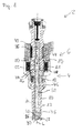
- An injection valve 2 ( Figure 1 ) that is in particular suitable for dosing fuel to an internal combustion engine comprises a valve assembly 4 and an actuator unit 6.
- the valve assembly 4 comprises a valve body 10 with a central longitudinal axis L and a cavity 11.
- a valve needle 12 is arranged in the cavity 11.
- the valve needle 12 can be moved in the cavity 11 in axial direction.
- the valve needle 12 is essentially cylindrical and has a barrel 14.
- the valve needle 12 is hollow with an inner recess 32.
- the actuator unit 6 has an armature 16 which is arranged in the cavity 11. A recess is provided in the armature 16 which takes up a part of the valve needle 12. The armature 16 can move relative to the valve needle 12. In the cavity 11 an armature spring 18 is arranged and is coupled to the armature 16 to exert a force on the armature 16 in axial direction.
- a recess 20 is provided in the valve body 10.
- a main spring 22 is arranged in the recess 20.
- the main spring 22 is mechanically coupled to the valve needle 12 to exert a force on the valve needle 12 in axial direction.
- the valve needle 10 comprises a seat part 28 which has a spherical shape.
- the seat part 28 closes the valve needle 10 at its lower end, i.e. at its tip.
- the seat part 28 rests on a seat body 26 being part of the valve body 10.
- a fluid flow through at least one injection nozzle 30 is prevented.
- the injection nozzle 30 may be an injection hole for example.
- a guide element 34 is arranged in the cavity 11.
- the guide element 34 is coupled to the valve needle 12.
- the guide element 34 is provided for guiding the valve needle 12 inside the valve body 10.
- the guide element 34 and the armature 16 are forming an interlocking device so that the armature 16 entrains the guide element 34 for an axial movement of the valve needle 12.
- the main spring 22 rests on a first spring seat being formed by the surface of the guide element 34 and a second spring seat being formed by a tube 36 which is provided in the recess 20.
- the actuator unit 6 preferably comprises an electromagnetic actuator with a coil 38.
- the coil 38, the armature 16 and parts of the valve body 10 are forming an electromagnetic circuit.
- the valve assembly 4 has a fluid inlet portion 40 which is provided in the valve body 10. Furthermore, the valve assembly 4 has a fluid outlet portion 42 which is provided in the valve body 10 near the seat body 26. In particular the fluid outlet portion 42 comprises the seat body 26. The fluid inlet portion 40 and the fluid outlet portion 42 may be arranged at opposite ends of the valve assembly in a longitudinal direction. The fluid inlet portion 40 is in hydraulic communication with the fluid outlet portion 42.
- the valve needle 12 has an upper end 44 facing the fluid inlet portion 40.
- the inner recess 32 of the valve needle 12 extends from the upper end 44 in direction to the fluid outlet portion 42. It is in particular formed by the barrel 14.
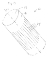
- Figures 2 and 3 show details of the valve needle 12 which has a plurality of orifices 46.
- the orifices 46 are arranged circumferentially on the barrel 14 of the valve needle 12 in a uniform manner.
- the orifices 46 form a sieve-like structure on the barrel 14 of the valve needle 12. Fluid may flow from the inner recess 32 inside the valve needle 12 through the orifices 46 in the barrel 14 to the fluid outlet portion 42.
- the orifices 46 have a diameter in the range between 0.03 and 0.07 mm, in particular in the case that the valve needle 12 of the injection valve 2 has a typical diameter of about 2-2.5 mm.
- the orifices 46 are laser-drilled.
- the orifices 46 are arranged in two zones Z1, Z2 of the valve needle 12.
- the two zones Z1, Z2 are distanced from each other in axial direction.
- the fluid is led from the fluid inlet portion 40 to the inner recess 32 of the valve needle 12.
- the main spring 22 forces the valve needle 12 in axial direction towards the seat body 26. It is depending on the force balance between the force on the valve needle 12 caused by the actuator unit 6 and the force on the valve needle 12 caused by the main spring 22 whether the valve needle 12 is in its closing position or not.
- the main spring 22 can exert a force on the valve needle 12 in a manner that the valve needle 12 can move in axial direction in its closing position, and the seat part 28 is forced to sealingly rest on the seat body 26.
- the armature spring 18 may dampen the movements of the armature 16 and the valve needle 12 in axial direction towards the seat body 26.
- the actuator unit 6 may exert a force on the valve needle 12.
- the force from the armature 16 on the valve needle 12 is contrary to the force on the valve needle 12 caused by the main spring 22.
- the valve needle 12 is able to move in axial direction out of the closing position.
- a homogenous fluid distribution downstream the outside of the barrel 14 of the valve needle 12 in an angular range of 360° may be obtained due to the orifices 46 being uniformly distributed over the circumference of the valve needle 12. Consequently, an appropriate shape of the spray of the injection valve 2 may be obtained.
- fluid which flows through the valve assembly 4 may be filtered from particles by the sieve-like structure formed by the orifices 46.
- the fluid may be filtered from particles which have been created inside the injection valve 2. Consequently, the fluid outlet portion 42 in particular between the seat part 28 and the seat body 26 may be kept free from particles.
- valve assembly 4 and the injection valve 2 may be obtained.
Landscapes
- Engineering & Computer Science (AREA)
- Chemical & Material Sciences (AREA)
- Combustion & Propulsion (AREA)
- Mechanical Engineering (AREA)
- General Engineering & Computer Science (AREA)
- Physics & Mathematics (AREA)
- Electromagnetism (AREA)
- Fuel-Injection Apparatus (AREA)
Abstract
A valve needle (12) for an injection valve (2) is specified. The valve needle (12) has a barrel (14) and an inner recess (32) extending from an upper end (44) in direction to a lower end of the valve needle (12) and enabling a fluid flow inside the valve needle (12). The valve needle (12) comprises a plurality of orifices (46) forming a sieve-like structure in the barrel (14). Further, a valve assembly (4) for an injection valve (2) and an injection valve (2) are specified.
Description
- The invention relates to a valve needle, a valve assembly for an injection valve and an injection valve.
- Injection valves are in widespread use, in particular for an internal combustion engine where they may be arranged in order to dose the fluid into an intake manifold of the internal combustion engine or directly into the combustion chamber of a cylinder of the internal combustion engine.
- Injection valves are manufactured in various forms in order to satisfy the various needs for the various combustion engines. Therefore, for example, their length, their diameter, and all the various elements of the injection valve being responsible for the way the fluid is dosed may vary in a wide range.
- In order to enhance the combustion process in view of degradation of unwanted emissions, the respective injection valve may be suited to dose fluids under high pressures. The pressures may be in the range of up to 200 bar for gasoline engines or in the range of more than 2000 bar for diesel engines.
- It is an object of the invention is to specify a valve needle, a valve assembly and an injection valve which are simple to be manufactured and/or which facilitate a reliable and precise function.
- This object is achieved by the features of the independent claims. Advantageous embodiments of the invention are given in the dependent claims.
- According to a first aspect a valve needle is specified. The valve needle is in particular a valve needle for an injection valve. The valve needle has an upper end and a tip opposite the upper end. Between the upper end and the tip, the valve needle comprises a barrel. In particular, an inner recess is formed by means of the barrel, the inner recess extending from the upper end in direction toward the tip. The valve needle comprises a plurality of orifices forming a sieve-like structure in the barrel of the valve needle. In particular, the barrel has at least one zone where it is perforated by the orifices. In this way, fluid may enter the recess of the valve needle at the upper end and leave the valve needle to the outside through the orifices.
- The expression "sieve-like structure" means in particular that the cross-sectional areas of the individual orifices are considerably smaller than the area-content of the perforated zone on an exterior surface of the barrel. For example, the cross-sectional area of each orifice has a value of 1/20 or less, preferably of 1/100 or less, for example of 1/500 or less of the area-content of the perforated zone on the exterior surface. In this way, the perforated zone may comprise a large number of orifices. The perforated zone has for example 50 orifices or more, preferably 150 orifices or more and in particular 300 orifices or more. In one embodiment, a plurality of the orifices are arranged subsequent to each other in an axial direction of the valve needle, i.e. in the direction from the upper end to the tip. For example 5 or more orifices, and in particular 50 or less orifices, are arranged in a row in the axial direction.
- According to another aspect, a valve assembly for an injection valve is specified. The valve assembly is in particular a valve assembly of an injection valve. The valve assembly comprises a valve body including a central longitudinal axis. The valve body has a cavity, the cavity having a fluid inlet portion and a fluid outlet portion. The valve assembly comprises a valve needle axially movable in the cavity. The valve needle is in particular the valve needle according to the first aspect. The valve needle prevents a fluid flow through the fluid outlet portion in a closing position and releases the fluid flow through the fluid outlet portion in further positions. The valve needle has an upper end facing the fluid inlet portion and an inner recess extending from the upper end in direction to the fluid outlet portion and enabling a fluid flow inside the valve needle. The valve needle comprises a plurality of orifices forming a sieve-like structure in a barrel of the valve needle and being designed to enable a fluid flow between the inner recess and the fluid outlet portion.
- This has the advantage that a direct fluid flow from the inner recess of the valve needle through the orifices to the fluid outlet portion may be obtained. As the orifices are forming the sieve-like structure the fluid may be filtered from particles before these particles may reach the fluid outlet portion. Furthermore, a very homogeneous distribution of the fluid downstream the valve needle may be obtained. Furthermore, pressure fluctuations of the fluid inside the valve body may be kept small. This can result in an excellent dynamic performance of the injection valve. Consequently, a long life-time of the valve assembly is possible.
- In an advantageous embodiment, the orifices are arranged evenly circumferentially in the barrel of the valve needle. In particular, the number of orifices per unit area is constant throughout the perforated zone in this case. For example, the orifices are arranged at the grid points of a uniform imaginary grid on the exterior surface. The orifices may be arranged in - preferably evenly spaced - columns and may be evenly spaced within the columns. The columns expediently extend in axial direction. The uniform circumferential arrangement has the advantage that a circumferentially homogeneous distribution of the fluid downstream the valve needle may be obtained.
- In a further advantageous embodiment, the orifices are arranged in at least two zones of the barrel of the valve needle. The at least two zones are distanced from each other in axial direction. In other words, the valve needle has two axially spaced perforated zones. On the one hand, this has the advantage that a homogeneous distribution of the fluid downstream the valve needle may be obtained. On the other hand, a draining or an emptying of the valve needle for service purposes may be carried out in an easy manner.
- In a further advantageous embodiment, the orifices have a diameter in the range between 0.03 and 0.07 mm. This has the advantage that a very homogeneous fluid flow from the inner recess of the valve needle to the fluid outlet portion via the openings may be obtained. Furthermore, it may be prevented that particles of a given size may reach the fluid outlet portion.
- In a further advantageous embodiment, the orifices are laser-drilled orifices. This has the advantage that the orifices may be produced in a simple manner. Consequently, a low cost solution for the orifices and the valve assembly may be obtained. Additionally, an exact size and exact positions of the orifices may be obtained. In particular, accurate and reproducible manufacturing is possible in this way.
- According to a further aspect, an injection valve with an actuator unit and a valve assembly according to the preceding aspect is specified. The actuator unit comprises an armature. The armature is arranged in the cavity and is moveable relative to the valve needle and is designed to mechanically cooperate with the valve needle.
- Exemplary embodiments of the invention are explained in the following with the aid of schematic drawings. These are as follows:
-
Figure 1 , an injection valve in a longitudinal section view, -
Figure 2 , an enlarged view of a valve needle in a perspective view, and -
Figure 3 , an enlarged view of a section of the valve needle in a perspective view. - Elements of the same design and function that appear in different illustrations are identified by the same reference characters.
- An injection valve 2 (
Figure 1 ) that is in particular suitable for dosing fuel to an internal combustion engine comprises a valve assembly 4 and anactuator unit 6. - The valve assembly 4 comprises a
valve body 10 with a central longitudinal axis L and a cavity 11. Avalve needle 12 is arranged in the cavity 11. Thevalve needle 12 can be moved in the cavity 11 in axial direction. Thevalve needle 12 is essentially cylindrical and has abarrel 14. Thevalve needle 12 is hollow with aninner recess 32. - The
actuator unit 6 has anarmature 16 which is arranged in the cavity 11. A recess is provided in thearmature 16 which takes up a part of thevalve needle 12. Thearmature 16 can move relative to thevalve needle 12. In the cavity 11 anarmature spring 18 is arranged and is coupled to thearmature 16 to exert a force on thearmature 16 in axial direction. - A
recess 20 is provided in thevalve body 10. Amain spring 22 is arranged in therecess 20. Themain spring 22 is mechanically coupled to thevalve needle 12 to exert a force on thevalve needle 12 in axial direction. - The
valve needle 10 comprises aseat part 28 which has a spherical shape. Theseat part 28 closes thevalve needle 10 at its lower end, i.e. at its tip. In the closing position of thevalve needle 12 theseat part 28 rests on aseat body 26 being part of thevalve body 10. In this case a fluid flow through at least oneinjection nozzle 30 is prevented. Theinjection nozzle 30 may be an injection hole for example. - A
guide element 34 is arranged in the cavity 11. Theguide element 34 is coupled to thevalve needle 12. Theguide element 34 is provided for guiding thevalve needle 12 inside thevalve body 10. Theguide element 34 and thearmature 16 are forming an interlocking device so that thearmature 16 entrains theguide element 34 for an axial movement of thevalve needle 12. - The
main spring 22 rests on a first spring seat being formed by the surface of theguide element 34 and a second spring seat being formed by atube 36 which is provided in therecess 20. - The
actuator unit 6 preferably comprises an electromagnetic actuator with a coil 38. The coil 38, thearmature 16 and parts of thevalve body 10 are forming an electromagnetic circuit. - The valve assembly 4 has a
fluid inlet portion 40 which is provided in thevalve body 10. Furthermore, the valve assembly 4 has afluid outlet portion 42 which is provided in thevalve body 10 near theseat body 26. In particular thefluid outlet portion 42 comprises theseat body 26. Thefluid inlet portion 40 and thefluid outlet portion 42 may be arranged at opposite ends of the valve assembly in a longitudinal direction. Thefluid inlet portion 40 is in hydraulic communication with thefluid outlet portion 42. - The
valve needle 12 has anupper end 44 facing thefluid inlet portion 40. Theinner recess 32 of thevalve needle 12 extends from theupper end 44 in direction to thefluid outlet portion 42. It is in particular formed by thebarrel 14. -
Figures 2 and3 show details of thevalve needle 12 which has a plurality oforifices 46. Theorifices 46 are arranged circumferentially on thebarrel 14 of thevalve needle 12 in a uniform manner. Theorifices 46 form a sieve-like structure on thebarrel 14 of thevalve needle 12. Fluid may flow from theinner recess 32 inside thevalve needle 12 through theorifices 46 in thebarrel 14 to thefluid outlet portion 42. Preferably, theorifices 46 have a diameter in the range between 0.03 and 0.07 mm, in particular in the case that thevalve needle 12 of the injection valve 2 has a typical diameter of about 2-2.5 mm. Preferably theorifices 46 are laser-drilled. - As may be seen in
Figure 2 , theorifices 46 are arranged in two zones Z1, Z2 of thevalve needle 12. The two zones Z1, Z2 are distanced from each other in axial direction. - In the following, the function of the injection valve is described in detail:
- The fluid is led from the
fluid inlet portion 40 to theinner recess 32 of thevalve needle 12. Themain spring 22 forces thevalve needle 12 in axial direction towards theseat body 26. It is depending on the force balance between the force on thevalve needle 12 caused by theactuator unit 6 and the force on thevalve needle 12 caused by themain spring 22 whether thevalve needle 12 is in its closing position or not. - When the
actuator unit 6 is de-energized, themain spring 22 can exert a force on thevalve needle 12 in a manner that thevalve needle 12 can move in axial direction in its closing position, and theseat part 28 is forced to sealingly rest on theseat body 26. Thearmature spring 18 may dampen the movements of thearmature 16 and thevalve needle 12 in axial direction towards theseat body 26. With advantage, the transfer of kinetic energy to theseat body 26 when thevalve needle 12 reaches the closing position is particularly low due to thearmature 16 which is axially movable with respect to thevalve needle 12. In the closing position of the valve needle 12 a fluid flow through thefluid outlet portion 42 and theinjection nozzle 30 is prevented. - If the
actuator unit 6 is energized, theactuator unit 6, in particular thearmature 16, may exert a force on thevalve needle 12. The force from thearmature 16 on thevalve needle 12 is contrary to the force on thevalve needle 12 caused by themain spring 22. Thus, thevalve needle 12 is able to move in axial direction out of the closing position. Outside of the closing position of thevalve needle 12, there is a gap between theseat body 26 and theseat part 28 of thevalve needle 12. This gap enables a fluid flow on fluid paths from theinner recess 32 of thevalve needle 12 through theorifices 46 in the zones Z1, Z2 to thefluid outlet portion 42 and further through theinjection nozzle 30. - In general, a homogenous fluid distribution downstream the outside of the
barrel 14 of thevalve needle 12 in an angular range of 360° may be obtained due to theorifices 46 being uniformly distributed over the circumference of thevalve needle 12. Consequently, an appropriate shape of the spray of the injection valve 2 may be obtained. - Furthermore, fluid which flows through the valve assembly 4 may be filtered from particles by the sieve-like structure formed by the
orifices 46. In particular, the fluid may be filtered from particles which have been created inside the injection valve 2. Consequently, thefluid outlet portion 42 in particular between theseat part 28 and theseat body 26 may be kept free from particles. - Additionally, due to the possibility to create a defined passage area of the
orifices 46 pressure fluctuations of the fluid inside thevalve body 10 may be kept small. - Consequently, a high reliability and a long life-time of the valve assembly 4 and the injection valve 2 may be obtained.
Claims (7)
- Valve needle (12) for an injection valve (2), the valve needle (12) having a barrel (14) and an inner recess (32) extending from an upper end (44) in direction to a lower end of the valve needle (12) and enabling a fluid flow inside the valve needle (12), wherein
the valve needle (12) comprises a plurality of orifices (46) forming a sieve-like structure in the barrel (14). - Valve needle (12) in accordance with claim 1, wherein the orifices (46) are arranged evenly circumferentially in the barrel (14) of the valve needle (12).
- Valve needle (12) in accordance with claim 1 or 2, wherein the orifices (46) are arranged in at least two zones (Z1, Z2) of the barrel (14) of the valve needle (12), the at least two zones (Z1, Z2) being distanced from each other in an axial direction.
- Valve needle (12) in accordance with one of the preceding claims, wherein the orifices (46) have a diameter in the range between 0.03 and 0.07 mm.
- Valve needle (12) in accordance with one of the preceding claims, wherein the orifices (46) are laser-drilled orifices.
- Valve assembly (4) for an injection valve (2), the valve assembly (4) comprising- a valve body (10) including a central longitudinal axis (L), the valve body (10) having a cavity (11), the cavity (11) having a fluid inlet portion (40) and a fluid outlet portion (42),- a valve needle (12) according to one of the preceding claims, wherein the valve needle is axially movable in the cavity (11), the valve needle (12) prevents a fluid flow through the fluid outlet portion (42) in a closing position and releases the fluid flow through the fluid outlet portion (42) in further positions, the upper end (44) of the valve needle (12) faces the fluid inlet portion (40) and the inner recess (32) extends from the upper end (44) in direction to the fluid outlet portion (42, the orifices (46) are designed to enable a fluid flow between the inner recess (32) and the fluid outlet portion (42).
- Injection valve (2) with an actuator unit (6) and a valve assembly (4) according to the preceding claim, wherein the actuator unit (6) comprises an armature (16) which is arranged in the cavity (11) and is moveable relative to the valve needle (12) and is designed to mechanically cooperate with the valve needle (12).
Priority Applications (1)
| Application Number | Priority Date | Filing Date | Title |
|---|---|---|---|
| EP12180211.0A EP2698525A1 (en) | 2012-08-13 | 2012-08-13 | Valve needle, valve assembly and injection valve |
Applications Claiming Priority (1)
| Application Number | Priority Date | Filing Date | Title |
|---|---|---|---|
| EP12180211.0A EP2698525A1 (en) | 2012-08-13 | 2012-08-13 | Valve needle, valve assembly and injection valve |
Publications (1)
| Publication Number | Publication Date |
|---|---|
| EP2698525A1 true EP2698525A1 (en) | 2014-02-19 |
Family
ID=46785233
Family Applications (1)
| Application Number | Title | Priority Date | Filing Date |
|---|---|---|---|
| EP12180211.0A Withdrawn EP2698525A1 (en) | 2012-08-13 | 2012-08-13 | Valve needle, valve assembly and injection valve |
Country Status (1)
| Country | Link |
|---|---|
| EP (1) | EP2698525A1 (en) |
Cited By (1)
| Publication number | Priority date | Publication date | Assignee | Title |
|---|---|---|---|---|
| CN106460747A (en) * | 2014-05-13 | 2017-02-22 | 德尔福国际业务卢森堡公司 | Fuel injector |
Citations (4)
| Publication number | Priority date | Publication date | Assignee | Title |
|---|---|---|---|---|
| DE102004053762A1 (en) * | 2004-11-08 | 2006-05-11 | Robert Bosch Gmbh | Valve needle for fluid valve has discharge holes with hole diameter of micrometer-range and which are distributed in large quantity over partial covering area of needle sleeve such that the needle sleeve itself forms filter |
| DE102005037552A1 (en) * | 2005-08-09 | 2007-02-15 | Robert Bosch Gmbh | Fuel injecting valve for internal combustion engine, has valve needle with filter unit that is integrated into valve needle as secondary filter and designed as cup filter cartridge hinged into internal longitudinal opening of valve needle |
| DE102005061424A1 (en) * | 2005-12-22 | 2007-07-05 | Robert Bosch Gmbh | Fuel injection valve for internal combustion engine, has movable actuating part with valve seat body including saw-tooth structure at outer periphery to provide firm connection with valve seat carrier |
| EP2354528A1 (en) * | 2010-01-15 | 2011-08-10 | Continental Automotive GmbH | Valve assembly and injection valve |
-
2012
- 2012-08-13 EP EP12180211.0A patent/EP2698525A1/en not_active Withdrawn
Patent Citations (4)
| Publication number | Priority date | Publication date | Assignee | Title |
|---|---|---|---|---|
| DE102004053762A1 (en) * | 2004-11-08 | 2006-05-11 | Robert Bosch Gmbh | Valve needle for fluid valve has discharge holes with hole diameter of micrometer-range and which are distributed in large quantity over partial covering area of needle sleeve such that the needle sleeve itself forms filter |
| DE102005037552A1 (en) * | 2005-08-09 | 2007-02-15 | Robert Bosch Gmbh | Fuel injecting valve for internal combustion engine, has valve needle with filter unit that is integrated into valve needle as secondary filter and designed as cup filter cartridge hinged into internal longitudinal opening of valve needle |
| DE102005061424A1 (en) * | 2005-12-22 | 2007-07-05 | Robert Bosch Gmbh | Fuel injection valve for internal combustion engine, has movable actuating part with valve seat body including saw-tooth structure at outer periphery to provide firm connection with valve seat carrier |
| EP2354528A1 (en) * | 2010-01-15 | 2011-08-10 | Continental Automotive GmbH | Valve assembly and injection valve |
Cited By (1)
| Publication number | Priority date | Publication date | Assignee | Title |
|---|---|---|---|---|
| CN106460747A (en) * | 2014-05-13 | 2017-02-22 | 德尔福国际业务卢森堡公司 | Fuel injector |
Similar Documents
| Publication | Publication Date | Title |
|---|---|---|
| EP2436910B1 (en) | Valve assembly for an injection valve and injection valve | |
| EP2535552B1 (en) | Valve assembly for an injection valve and injection valve | |
| EP2333297B1 (en) | Valve assembly for an injection valve and injection valve | |
| EP2000662B1 (en) | Adjusting and filter arrangement for an injection valve and injection valve | |
| EP2884090A1 (en) | Nozzle body and fuel injection valve | |
| EP2386745B1 (en) | A fuel injector for internal combustion engines | |
| CN104583576B (en) | Valve assemblies and injection valves for injection valves | |
| CN102713245A (en) | Fuel injection valve | |
| EP2354528B1 (en) | Valve assembly and injection valve | |
| KR20140033092A (en) | Valve for metering a flowing medium | |
| EP2375051A1 (en) | Valve assembly for an injection valve and injection valve | |
| US10001100B2 (en) | Valve assembly and fluid injector for a combustion engine | |
| EP2149699A1 (en) | Fuel injector | |
| CN105275694A (en) | Restrictive flow passage in common rail injectors | |
| US20070176132A1 (en) | Valve Assembly For An Injection Valve And Injection Valve | |
| EP2218900B1 (en) | Valve assembly for an injection valve and injection valve | |
| EP2698527A1 (en) | Valve assembly for an injection valve and injection valve | |
| EP2282042B1 (en) | Valve assembly and injection valve | |
| CN108138734B (en) | Fluid injection device for internal combustion engine | |
| EP2354531A1 (en) | Valve assembly for an injection valve and injection valve | |
| EP2426350A1 (en) | Valve assembly for an injection valve and injection valve | |
| US20150300304A1 (en) | Injection valve | |
| EP2703633A1 (en) | Valve assembly for an injection valve and injection valve | |
| EP2466109A1 (en) | Valve assembly for an injection valve and injection valve | |
| EP2385239A1 (en) | Valve assembly for an injection valve and injection valve |
Legal Events
| Date | Code | Title | Description |
|---|---|---|---|
| AK | Designated contracting states |
Kind code of ref document: A1 Designated state(s): AL AT BE BG CH CY CZ DE DK EE ES FI FR GB GR HR HU IE IS IT LI LT LU LV MC MK MT NL NO PL PT RO RS SE SI SK SM TR |
|
| AX | Request for extension of the european patent |
Extension state: BA ME |
|
| PUAI | Public reference made under article 153(3) epc to a published international application that has entered the european phase |
Free format text: ORIGINAL CODE: 0009012 |
|
| STAA | Information on the status of an ep patent application or granted ep patent |
Free format text: STATUS: THE APPLICATION IS DEEMED TO BE WITHDRAWN |
|
| 18D | Application deemed to be withdrawn |
Effective date: 20140820 |