EP2698451A2 - Revêtement formant une barrière environnementale résistant à la cavitation - Google Patents
Revêtement formant une barrière environnementale résistant à la cavitation Download PDFInfo
- Publication number
- EP2698451A2 EP2698451A2 EP20130179467 EP13179467A EP2698451A2 EP 2698451 A2 EP2698451 A2 EP 2698451A2 EP 20130179467 EP20130179467 EP 20130179467 EP 13179467 A EP13179467 A EP 13179467A EP 2698451 A2 EP2698451 A2 EP 2698451A2
- Authority
- EP
- European Patent Office
- Prior art keywords
- coat layer
- bond coat
- silicon
- environmental barrier
- barrier coating
- Prior art date
- Legal status (The legal status is an assumption and is not a legal conclusion. Google has not performed a legal analysis and makes no representation as to the accuracy of the status listed.)
- Withdrawn
Links
Images

Classifications
-
- C—CHEMISTRY; METALLURGY
- C23—COATING METALLIC MATERIAL; COATING MATERIAL WITH METALLIC MATERIAL; CHEMICAL SURFACE TREATMENT; DIFFUSION TREATMENT OF METALLIC MATERIAL; COATING BY VACUUM EVAPORATION, BY SPUTTERING, BY ION IMPLANTATION OR BY CHEMICAL VAPOUR DEPOSITION, IN GENERAL; INHIBITING CORROSION OF METALLIC MATERIAL OR INCRUSTATION IN GENERAL
- C23C—COATING METALLIC MATERIAL; COATING MATERIAL WITH METALLIC MATERIAL; SURFACE TREATMENT OF METALLIC MATERIAL BY DIFFUSION INTO THE SURFACE, BY CHEMICAL CONVERSION OR SUBSTITUTION; COATING BY VACUUM EVAPORATION, BY SPUTTERING, BY ION IMPLANTATION OR BY CHEMICAL VAPOUR DEPOSITION, IN GENERAL
- C23C28/00—Coating for obtaining at least two superposed coatings either by methods not provided for in a single one of groups C23C2/00 - C23C26/00 or by combinations of methods provided for in subclasses C23C and C25C or C25D
- C23C28/04—Coating for obtaining at least two superposed coatings either by methods not provided for in a single one of groups C23C2/00 - C23C26/00 or by combinations of methods provided for in subclasses C23C and C25C or C25D only coatings of inorganic non-metallic material
- C23C28/042—Coating for obtaining at least two superposed coatings either by methods not provided for in a single one of groups C23C2/00 - C23C26/00 or by combinations of methods provided for in subclasses C23C and C25C or C25D only coatings of inorganic non-metallic material including a refractory ceramic layer, e.g. refractory metal oxides, ZrO2, rare earth oxides
-
- C—CHEMISTRY; METALLURGY
- C04—CEMENTS; CONCRETE; ARTIFICIAL STONE; CERAMICS; REFRACTORIES
- C04B—LIME, MAGNESIA; SLAG; CEMENTS; COMPOSITIONS THEREOF, e.g. MORTARS, CONCRETE OR LIKE BUILDING MATERIALS; ARTIFICIAL STONE; CERAMICS; REFRACTORIES; TREATMENT OF NATURAL STONE
- C04B41/00—After-treatment of mortars, concrete, artificial stone or ceramics; Treatment of natural stone
- C04B41/009—After-treatment of mortars, concrete, artificial stone or ceramics; Treatment of natural stone characterised by the material treated
-
- C—CHEMISTRY; METALLURGY
- C04—CEMENTS; CONCRETE; ARTIFICIAL STONE; CERAMICS; REFRACTORIES
- C04B—LIME, MAGNESIA; SLAG; CEMENTS; COMPOSITIONS THEREOF, e.g. MORTARS, CONCRETE OR LIKE BUILDING MATERIALS; ARTIFICIAL STONE; CERAMICS; REFRACTORIES; TREATMENT OF NATURAL STONE
- C04B41/00—After-treatment of mortars, concrete, artificial stone or ceramics; Treatment of natural stone
- C04B41/45—Coating or impregnating, e.g. injection in masonry, partial coating of green or fired ceramics, organic coating compositions for adhering together two concrete elements
- C04B41/52—Multiple coating or impregnating multiple coating or impregnating with the same composition or with compositions only differing in the concentration of the constituents, is classified as single coating or impregnation
-
- C—CHEMISTRY; METALLURGY
- C04—CEMENTS; CONCRETE; ARTIFICIAL STONE; CERAMICS; REFRACTORIES
- C04B—LIME, MAGNESIA; SLAG; CEMENTS; COMPOSITIONS THEREOF, e.g. MORTARS, CONCRETE OR LIKE BUILDING MATERIALS; ARTIFICIAL STONE; CERAMICS; REFRACTORIES; TREATMENT OF NATURAL STONE
- C04B41/00—After-treatment of mortars, concrete, artificial stone or ceramics; Treatment of natural stone
- C04B41/80—After-treatment of mortars, concrete, artificial stone or ceramics; Treatment of natural stone of only ceramics
- C04B41/81—Coating or impregnation
- C04B41/89—Coating or impregnation for obtaining at least two superposed coatings having different compositions
- C04B41/90—Coating or impregnation for obtaining at least two superposed coatings having different compositions at least one coating being a metal
-
- C—CHEMISTRY; METALLURGY
- C23—COATING METALLIC MATERIAL; COATING MATERIAL WITH METALLIC MATERIAL; CHEMICAL SURFACE TREATMENT; DIFFUSION TREATMENT OF METALLIC MATERIAL; COATING BY VACUUM EVAPORATION, BY SPUTTERING, BY ION IMPLANTATION OR BY CHEMICAL VAPOUR DEPOSITION, IN GENERAL; INHIBITING CORROSION OF METALLIC MATERIAL OR INCRUSTATION IN GENERAL
- C23C—COATING METALLIC MATERIAL; COATING MATERIAL WITH METALLIC MATERIAL; SURFACE TREATMENT OF METALLIC MATERIAL BY DIFFUSION INTO THE SURFACE, BY CHEMICAL CONVERSION OR SUBSTITUTION; COATING BY VACUUM EVAPORATION, BY SPUTTERING, BY ION IMPLANTATION OR BY CHEMICAL VAPOUR DEPOSITION, IN GENERAL
- C23C28/00—Coating for obtaining at least two superposed coatings either by methods not provided for in a single one of groups C23C2/00 - C23C26/00 or by combinations of methods provided for in subclasses C23C and C25C or C25D
- C23C28/04—Coating for obtaining at least two superposed coatings either by methods not provided for in a single one of groups C23C2/00 - C23C26/00 or by combinations of methods provided for in subclasses C23C and C25C or C25D only coatings of inorganic non-metallic material
- C23C28/044—Coating for obtaining at least two superposed coatings either by methods not provided for in a single one of groups C23C2/00 - C23C26/00 or by combinations of methods provided for in subclasses C23C and C25C or C25D only coatings of inorganic non-metallic material coatings specially adapted for cutting tools or wear applications
-
- F—MECHANICAL ENGINEERING; LIGHTING; HEATING; WEAPONS; BLASTING
- F01—MACHINES OR ENGINES IN GENERAL; ENGINE PLANTS IN GENERAL; STEAM ENGINES
- F01D—NON-POSITIVE DISPLACEMENT MACHINES OR ENGINES, e.g. STEAM TURBINES
- F01D5/00—Blades; Blade-carrying members; Heating, heat-insulating, cooling or antivibration means on the blades or the members
- F01D5/12—Blades
- F01D5/28—Selecting particular materials; Particular measures relating thereto; Measures against erosion or corrosion
- F01D5/284—Selection of ceramic materials
-
- F—MECHANICAL ENGINEERING; LIGHTING; HEATING; WEAPONS; BLASTING
- F01—MACHINES OR ENGINES IN GENERAL; ENGINE PLANTS IN GENERAL; STEAM ENGINES
- F01D—NON-POSITIVE DISPLACEMENT MACHINES OR ENGINES, e.g. STEAM TURBINES
- F01D5/00—Blades; Blade-carrying members; Heating, heat-insulating, cooling or antivibration means on the blades or the members
- F01D5/12—Blades
- F01D5/28—Selecting particular materials; Particular measures relating thereto; Measures against erosion or corrosion
- F01D5/288—Protective coatings for blades
-
- F—MECHANICAL ENGINEERING; LIGHTING; HEATING; WEAPONS; BLASTING
- F05—INDEXING SCHEMES RELATING TO ENGINES OR PUMPS IN VARIOUS SUBCLASSES OF CLASSES F01-F04
- F05D—INDEXING SCHEME FOR ASPECTS RELATING TO NON-POSITIVE-DISPLACEMENT MACHINES OR ENGINES, GAS-TURBINES OR JET-PROPULSION PLANTS
- F05D2300/00—Materials; Properties thereof
- F05D2300/20—Oxide or non-oxide ceramics
- F05D2300/21—Oxide ceramics
- F05D2300/211—Silica
Definitions
- the present invention generally relates to coating systems suitable for protecting components exposed to high-temperature environments, such as the hostile thermal environment of a gas turbine engine. More particularly, this invention is directed to a bond coat layer on a silicon-containing region of a component such as a ceramic matrix composite (CMC) and to the incorporation of dopants in the grain boundaries of the bond coat layer to improve delamination resistance and cavitation resistance of the environmental barrier coating system (EBC).
- CMC ceramic matrix composite
- a protective coating is beneficial or required for a Si-containing material.
- Such coatings should provide environmental protection by inhibiting the major mechanism for degradation of Si-containing materials in a corrosive water-containing environment, namely, the formation of volatile silicon monoxide (SiO) and silicon hydroxide (Si(OH) 4 ) products.
- a coating system having these functions will be referred to below as an environmental barrier coating (EBC) system.
- Important properties for the coating material include a coefficient of thermal expansion (CTE) compatible with the SiC-containing material, low permeability for oxidants, low thermal conductivity, stability and chemical compatibility with the Si-containing material and silica scale formed from oxidation.
- CTE coefficient of thermal expansion
- Mullite (3Al 2 O 3 .2SiO 2 ), barium-strontium-aluminosilicate (BSAS; (Ba1-xSrx)O-Al 2 O 3 -SiO 2 ) and other alkaline earth aluminosilicates have been proposed as protective coatings for Si-containing materials.
- BSAS barium-strontium-aluminosilicate
- BAS barium-strontium-aluminosilicate
- other alkaline earth aluminosilicates have been proposed as protective coatings for Si-containing materials.
- U.S. Patent No. 5,496,644 to Lee et al. and U.S. Patent No. 5,869,146 to McCluskey et al. disclose the use of mullite and U.S. Patent Nos. 6,254,935 , 6,365,288 , 6,387,456 and 6,410,148 to Eaton et al.
- BSAS barrier coatings are described as being bonded to a silicon-containing substrate with an intermediate layer (bond coat layer) that may be, among other possible materials, mullite or a mixture of mullite and BSAS.
- bond coat layer may be, among other possible materials, mullite or a mixture of mullite and BSAS.
- the bond coat layer comprises silicon
- the silicon preferentially reacts with oxygen to form a non-gaseous product.
- the resulting silicon oxide (SiO 2 ) layer while sometimes desirable, may reduce the cavitation resistance of the EBC system and even cause delamination or spallation due to a CTE mismatch with other EBC layers. Therefore, methods and systems which reduce the growth of the silicon oxide layer are desirable for certain applications.
- the present invention provides an environmental barrier coating, a method of application thereof, and an article made thereby suitable for protecting components exposed to high-temperature environments with improved delamination resistance and cavitation resistance.
- an environmental barrier coating system for a silicon-containing substrate that includes a bond coat layer on the silicon-containing substrate and at least one ceramic environmental barrier layer on the bond coat layer.
- the bond coat layer includes silicon and at least one doping material including elemental titanium. The doping material is located at grain boundaries within the bond coat layer in sufficient quantity to improve the delamination resistance and the cavitation resistance of increase the bond coat layer.
- an article includes a silicon-containing substrate and an environmental barrier coating system on the silicon-containing substrate.
- the environmental barrier coating system includes a bond coat layer on the silicon-containing substrate and at least one ceramic environmental barrier layer on the bond coat layer.
- the bond coat layer includes silicon and at least one doping material including elemental titanium. The doping material is located at grain boundaries within the bond coat layer in sufficient quantity to improve the delamination resistance and the cavitation resistance of increase the bond coat layer.
- a method of applying an environmental barrier coating system on a silicon-containing substrate that includes forming a bond coat layer that includes silicon on the silicon-containing substrate, doping the bond coat layer with a doping material that includes elemental titanium in a manner so that the doping material is located at grain boundaries within the bond coat layer in sufficient quantity to improve the delamination resistance and cavitation resistance of the bond coat layer, and applying at least one ceramic layer on the bond coat layer.
- a technical effect of the invention is the ability to protect components exposed to high-temperature environments with improved EBC systems with improved delamination resistance and cavitation resistance.
- Embodiments described herein generally relate to environmental barrier coating (EBC) systems for high temperature ceramic components.
- EBC environmental barrier coating
- CMC refers to silicon-containing matrix and reinforcing materials.
- CMC systems acceptable for use herein can include, but should not be limited to, materials having a matrix and reinforcing fibers comprising silicon carbide, silicon nitride, and mixtures thereof.
- monolithic ceramics refers to materials comprising silicon carbide, silicon nitride, and mixtures thereof. CMC systems and monolithic ceramics are collectively referred to herein as ceramics.
- the EBC systems herein may be suitable for application to ceramic components, or simply components, found in high temperature environments (e.g. operating temperatures of about 2500°C), such as those present in turbomachinery, including but not limited to turbine engines such as those used in the power generating industry.
- high temperature environments e.g. operating temperatures of about 2500°C
- turbine engines such as those used in the power generating industry.
- FIG. 1 represents an article 10 as comprising an EBC system 14 on a silicon-containing substrate 12, which can include a bond coat layer 16 adjacent to the silicon-containing substrate 12, an optional silica layer 18 adjacent to the bond coat layer 16, at least one optional transition layer 20 adjacent to the bond coat layer 16 (or the silica layer 18 if present), and an outer layer 22 adjacent to the transition layer 20.
- the outer layer 22 forms an outermost surface 24 of the component 10.
- the EBC system 14 has at least one ceramic layer 18, 20, and/or 22 on the bond coat layer 16.
- a preferred composition for the bond coat layer 16 comprises elemental silicon or a silicon-containing composition, such as SiC, Si3N4, etc.
- Suitable materials for the transition layer 20 include, but are not limited to, silicates, alkaline-earth metal aluminosilicates and/or rare-earth metal silicates, and particularly compounds of rare-earth oxides and silicates such as barium-strontium-aluminosilicates (BSAS) and other alkaline-earth aluminosilicates.
- BSAS barium-strontium-aluminosilicates
- Suitable materials for the outer layer 22 include, but are not limited to, YSZ alone or with additions of rare-earth oxides capable of promoting properties of the outer layer 22.
- Outer layers formed of other ceramic materials are also foreseeable, for example, zirconate or perovskite materials.
- the bond coat layer 16 may be applied by plasma spray processes, chemical vapor deposition (CVD) processes, electron beam physical vapor deposition (EBPVD) processes, dipping in molten silicon, sputtering processes, and other conventional application processes known to those skilled in the art.
- the forming of the bond coat layer 16 may be followed by a conventional heat treatment process known to those skilled in the art.
- strategic proportional doping of the bond coat layer 16 is performed after the heat treatment.
- the term strategic proportional doping refers to any doping technique that allows for one or more doping materials to be directly applied to grain boundaries within at least a surface region of the bond coat layer 16.
- suitable doping processes may include ion implantation, impregnation, or liquid infiltration.
- the bond coat layer 16 is doped with one or more doping materials consisting entirely of elemental titanium or comprising a compound comprising elemental titanium.
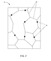
- FIG. 2 schematically represents a microstructure of the bond coat layer 16 having doping materials 28 located on or near the grain boundaries 26 of the bond coat layer 16. It will be appreciated that FIG. 2 is for illustrative purposes only and is not to scale.
- the doping material 28 is heterogeneously deposited over a region or the entirety of the outermost surface 24 of the bond coat layer 16.
- the doping material 28 will likely preferentially diffuse to the grain boundaries 26 within the bond coat layer 16 as the grain boundary energy is reduced by the doping material 28.
- the doping material 28 accumulates at the grain boundaries 26 within the bond coat layer 16 in sufficient quantity to improve the delamination resistance and cavitation resistance of the bond coat layer 16.
- a sufficient quantity of the doping material 28 located at the grain boundaries 26 is dependent on the region covered and the sticking coefficient (that is, the ratio of the average number of gas particles sticking to the surface to the average number gas particles incident on the surface) of the doping material 28 used as well as other parameters such as the temperature of the bond coat layer 16.
- at least five percent by weight doping material 28 is located at the grain boundaries 26, and more preferably between about five and about fifteen percent by weight.
- the elemental titanium should be present in the bond coat layer 16 in an amount of at least five weight percent to have the desired effect on the CTE of the bond coat layer 16, but not exceed about fifteen weight percent in order to avoid any negative impact on the physical properties of the bond coat layer 16.
- the elemental titanium is present in the bond coat layer 16 in an amount of about five to about ten weight percent, and more preferably in an amount of about seven to about ten weight percent.
- the CTE of the bond coat layer 16 may be increased to reduce the mismatch between the bond coat layer 16 and the other layers 18, 20 and 22 of the EBC system 14.
- the CTE of fused silicon is about 0.55 ppm/°C and the CTE of SiC-SiC CMC materials is about 4 ppm/°C.
- YSZ commonly used as an outermost layer 22 in EBC systems, has a CTE of about 10 ppm/°C for YSZ.
- doping the bond coat layer 16 with the doping material 28 which contains elemental titanium with a CTE of about 9.5 ppm/°C, can increase the CTE of the bond coat layer 16 to be closer to the CTE of the other layers in the EBC system 14.
- the CTE of the titanium will compensate for the fused silica and hinder the formation of voids within the bond coat layer 16 typically caused by the CTE mismatch reducing conventional cavitation problems.
- the CTE of the bond coat layer 16 is at least about 2.6 ppm/°C, and more preferably is about 4 ppm/°C to about 5 ppm/°C.
- the doping material 28 preferably acts as a barrier to grain boundary sliding by pinning down dislocation clouds around the grain boundaries 26.
- the doping material 28 acts as the obstacles to the grain boundary movements and reduces the motions of dislocations, thereby increasing the grain boundary sliding activation energy in the bond coat layer 16.
- the system then acts similar to the classic Cottrell Atmosphere, where the doping material 28 gets caught by the dislocations and consequently strengthens the matrix of the bond coat layer 16. This increase in grain boundary sliding activation energy substantially improves the overall delamination resistance and cavitation resistance of the bond coat layer 16.
- Thermal growth of a silicon dioxide (SiO 2 ) layer on the bond coat layer 16 may be reduced due to the presence of the doping material 28 further reducing the CTE mismatch within the EBC system 14.
- the titanium within the bond coat layer 16 competes with the silicon for oxygen to form titanium dioxide rather than silicon dioxide. This competition may result in an oxygen deficiency near the surface of the bond coat layer 16. This deficiency will reduce the formation of SiO and SiO 2 which can reduce further CTE mismatch within the EBC system 14.
Landscapes
- Chemical & Material Sciences (AREA)
- Engineering & Computer Science (AREA)
- Ceramic Engineering (AREA)
- Materials Engineering (AREA)
- Organic Chemistry (AREA)
- Mechanical Engineering (AREA)
- Structural Engineering (AREA)
- Inorganic Chemistry (AREA)
- Chemical Kinetics & Catalysis (AREA)
- Metallurgy (AREA)
- General Engineering & Computer Science (AREA)
- Turbine Rotor Nozzle Sealing (AREA)
Applications Claiming Priority (1)
| Application Number | Priority Date | Filing Date | Title |
|---|---|---|---|
| US13/585,998 US20140050929A1 (en) | 2012-08-15 | 2012-08-15 | Cavitation-resistant environmental barrier coatings |
Publications (1)
| Publication Number | Publication Date |
|---|---|
| EP2698451A2 true EP2698451A2 (fr) | 2014-02-19 |
Family
ID=48948282
Family Applications (1)
| Application Number | Title | Priority Date | Filing Date |
|---|---|---|---|
| EP20130179467 Withdrawn EP2698451A2 (fr) | 2012-08-15 | 2013-08-06 | Revêtement formant une barrière environnementale résistant à la cavitation |
Country Status (3)
| Country | Link |
|---|---|
| US (1) | US20140050929A1 (fr) |
| EP (1) | EP2698451A2 (fr) |
| CN (1) | CN103587156A (fr) |
Cited By (1)
| Publication number | Priority date | Publication date | Assignee | Title |
|---|---|---|---|---|
| EP2698452A3 (fr) * | 2012-08-16 | 2016-09-14 | General Electric Company | Revêtements formant une barrière environnementale résistant au fluage |
Families Citing this family (9)
| Publication number | Priority date | Publication date | Assignee | Title |
|---|---|---|---|---|
| US10214456B2 (en) | 2016-09-16 | 2019-02-26 | General Electric Company | Silicon compositions containing boron and methods of forming the same |
| US10294112B2 (en) | 2016-09-16 | 2019-05-21 | General Electric Company | Silicon compositions containing boron and methods of forming the same |
| US10787391B2 (en) | 2016-09-16 | 2020-09-29 | General Electric Company | Silicon-based materials containing boron |
| US9944563B2 (en) | 2016-09-16 | 2018-04-17 | General Electric Company | Silicon-based materials containing indium and methods of forming the same |
| US10214457B2 (en) | 2016-09-16 | 2019-02-26 | General Electric Company | Compositions containing gallium and/or indium and methods of forming the same |
| US10138740B2 (en) | 2016-09-16 | 2018-11-27 | General Electric Company | Silicon-based materials containing gallium and methods of forming the same |
| US10259716B2 (en) | 2016-09-16 | 2019-04-16 | General Electric Company | Boron doped rare earth metal oxide compound |
| US20200039886A1 (en) * | 2018-07-31 | 2020-02-06 | General Electric Company | Silicon Bond Coat with Amorphous Structure and Methods of Its Formation |
| US11492298B2 (en) * | 2018-07-31 | 2022-11-08 | General Electric Company | Silicon bond coat with columnar grains and methods of its formation |
Citations (4)
| Publication number | Priority date | Publication date | Assignee | Title |
|---|---|---|---|---|
| US5496644A (en) | 1993-03-15 | 1996-03-05 | The United States Of America As Represented By The Administrator Of The National Aeronautics And Space Administration | Plasma sprayed mullite coatings on silicon-base ceramics |
| US5869146A (en) | 1997-11-12 | 1999-02-09 | United Technologies Corporation | Plasma sprayed mullite coatings on silicon based ceramic materials |
| US6254935B1 (en) | 1999-04-15 | 2001-07-03 | United Technologies Corporation | Method for applying a barrier layer to a silicon based substrate |
| US6387456B1 (en) | 1999-04-15 | 2002-05-14 | General Electric Company | Silicon based substrate with environmental/thermal barrier layer |
Family Cites Families (2)
| Publication number | Priority date | Publication date | Assignee | Title |
|---|---|---|---|---|
| US7060360B2 (en) * | 2003-05-22 | 2006-06-13 | United Technologies Corporation | Bond coat for silicon based substrates |
| US20130177441A1 (en) * | 2012-01-11 | 2013-07-11 | General Electric Company | Compositional Bond Coat for Hindering/Reversing Creep Degradation in Environmental Barrier Coatings |
-
2012
- 2012-08-15 US US13/585,998 patent/US20140050929A1/en not_active Abandoned
-
2013
- 2013-08-06 EP EP20130179467 patent/EP2698451A2/fr not_active Withdrawn
- 2013-08-14 CN CN201310352389.1A patent/CN103587156A/zh active Pending
Patent Citations (6)
| Publication number | Priority date | Publication date | Assignee | Title |
|---|---|---|---|---|
| US5496644A (en) | 1993-03-15 | 1996-03-05 | The United States Of America As Represented By The Administrator Of The National Aeronautics And Space Administration | Plasma sprayed mullite coatings on silicon-base ceramics |
| US5869146A (en) | 1997-11-12 | 1999-02-09 | United Technologies Corporation | Plasma sprayed mullite coatings on silicon based ceramic materials |
| US6254935B1 (en) | 1999-04-15 | 2001-07-03 | United Technologies Corporation | Method for applying a barrier layer to a silicon based substrate |
| US6365288B1 (en) | 1999-04-15 | 2002-04-02 | United Technologies Corporation | Method for applying a barrier layer to a silicon based substrate |
| US6387456B1 (en) | 1999-04-15 | 2002-05-14 | General Electric Company | Silicon based substrate with environmental/thermal barrier layer |
| US6410148B1 (en) | 1999-04-15 | 2002-06-25 | General Electric Co. | Silicon based substrate with environmental/ thermal barrier layer |
Cited By (1)
| Publication number | Priority date | Publication date | Assignee | Title |
|---|---|---|---|---|
| EP2698452A3 (fr) * | 2012-08-16 | 2016-09-14 | General Electric Company | Revêtements formant une barrière environnementale résistant au fluage |
Also Published As
| Publication number | Publication date |
|---|---|
| US20140050929A1 (en) | 2014-02-20 |
| CN103587156A (zh) | 2014-02-19 |
Similar Documents
| Publication | Publication Date | Title |
|---|---|---|
| EP2698451A2 (fr) | Revêtement formant une barrière environnementale résistant à la cavitation | |
| EP2698452B1 (fr) | Revêtements formant une barrière environnementale résistant au fluage | |
| EP2503027B1 (fr) | Revêtements résistant à la corrosion à chaud et composants ainsi protégés | |
| US7357994B2 (en) | Thermal/environmental barrier coating system for silicon-containing materials | |
| EP1685083B1 (fr) | Revetements constituant une barriere contre l'oxydation pour ceramiques a base de silicium | |
| EP1734025B1 (fr) | Système de couches barrière thermique/environnementale pour materiaux contenant du silicium | |
| EP2537822B1 (fr) | Article composite incluant une couche comprenant d'oxycarbure de silicium | |
| EP1683772B1 (fr) | Barrière environnementale/thermique avec une couche de transition pour un substrat à base de silicium | |
| US6607852B2 (en) | Environmental/thermal barrier coating system with silica diffusion barrier layer | |
| EP1683775B1 (fr) | Couche barrière thermique/environnementale pour un substrat contenant du silicium | |
| EP2202212B1 (fr) | Composants comportant des compositions d'atténuation CMAS | |
| EP2918570B1 (fr) | Articles avec revêtements protecteurs environnementaux hermétiques à dilatation réduite et procédés de fabrication de ceux-ci | |
| EP1142850B1 (fr) | Barriere environnementale/thermique pour un substrat à base de silicium | |
| EP1683774B1 (fr) | Couche barrière thermique/environnementale pour un substrat contenant du silicium | |
| EP1683773B1 (fr) | Revêtement protecteur contenant une couche barrière physique pour substrats contenant de silicium | |
| EP3186211B1 (fr) | Article à utiliser à haute température | |
| US7354651B2 (en) | Bond coat for corrosion resistant EBC for silicon-containing substrate and processes for preparing same | |
| EP2287138A2 (fr) | Techniques pour le revêtement par dépôt sur un substrat en céramique | |
| US20060166019A1 (en) | Thermal/environmental barrier coating for silicon-comprising materials | |
| US10851656B2 (en) | Multilayer environmental barrier coating |
Legal Events
| Date | Code | Title | Description |
|---|---|---|---|
| AK | Designated contracting states |
Kind code of ref document: A2 Designated state(s): AL AT BE BG CH CY CZ DE DK EE ES FI FR GB GR HR HU IE IS IT LI LT LU LV MC MK MT NL NO PL PT RO RS SE SI SK SM TR |
|
| AX | Request for extension of the european patent |
Extension state: BA ME |
|
| PUAI | Public reference made under article 153(3) epc to a published international application that has entered the european phase |
Free format text: ORIGINAL CODE: 0009012 |
|
| STAA | Information on the status of an ep patent application or granted ep patent |
Free format text: STATUS: THE APPLICATION IS DEEMED TO BE WITHDRAWN |
|
| 18D | Application deemed to be withdrawn |
Effective date: 20160301 |