EP2698450A1 - MCrAIX coating with different chrome and aluminium contents - Google Patents
MCrAIX coating with different chrome and aluminium contents Download PDFInfo
- Publication number
- EP2698450A1 EP2698450A1 EP13005373.9A EP13005373A EP2698450A1 EP 2698450 A1 EP2698450 A1 EP 2698450A1 EP 13005373 A EP13005373 A EP 13005373A EP 2698450 A1 EP2698450 A1 EP 2698450A1
- Authority
- EP
- European Patent Office
- Prior art keywords
- layer
- mcralx
- yttrium
- content
- metal layer
- Prior art date
- Legal status (The legal status is an assumption and is not a legal conclusion. Google has not performed a legal analysis and makes no representation as to the accuracy of the status listed.)
- Withdrawn
Links
Images


Classifications
-
- C—CHEMISTRY; METALLURGY
- C23—COATING METALLIC MATERIAL; COATING MATERIAL WITH METALLIC MATERIAL; CHEMICAL SURFACE TREATMENT; DIFFUSION TREATMENT OF METALLIC MATERIAL; COATING BY VACUUM EVAPORATION, BY SPUTTERING, BY ION IMPLANTATION OR BY CHEMICAL VAPOUR DEPOSITION, IN GENERAL; INHIBITING CORROSION OF METALLIC MATERIAL OR INCRUSTATION IN GENERAL
- C23C—COATING METALLIC MATERIAL; COATING MATERIAL WITH METALLIC MATERIAL; SURFACE TREATMENT OF METALLIC MATERIAL BY DIFFUSION INTO THE SURFACE, BY CHEMICAL CONVERSION OR SUBSTITUTION; COATING BY VACUUM EVAPORATION, BY SPUTTERING, BY ION IMPLANTATION OR BY CHEMICAL VAPOUR DEPOSITION, IN GENERAL
- C23C28/00—Coating for obtaining at least two superposed coatings either by methods not provided for in a single one of groups C23C2/00 - C23C26/00 or by combinations of methods provided for in subclasses C23C and C25C or C25D
- C23C28/02—Coating for obtaining at least two superposed coatings either by methods not provided for in a single one of groups C23C2/00 - C23C26/00 or by combinations of methods provided for in subclasses C23C and C25C or C25D only coatings only including layers of metallic material
- C23C28/021—Coating for obtaining at least two superposed coatings either by methods not provided for in a single one of groups C23C2/00 - C23C26/00 or by combinations of methods provided for in subclasses C23C and C25C or C25D only coatings only including layers of metallic material including at least one metal alloy layer
- C23C28/022—Coating for obtaining at least two superposed coatings either by methods not provided for in a single one of groups C23C2/00 - C23C26/00 or by combinations of methods provided for in subclasses C23C and C25C or C25D only coatings only including layers of metallic material including at least one metal alloy layer with at least one MCrAlX layer
-
- C—CHEMISTRY; METALLURGY
- C23—COATING METALLIC MATERIAL; COATING MATERIAL WITH METALLIC MATERIAL; CHEMICAL SURFACE TREATMENT; DIFFUSION TREATMENT OF METALLIC MATERIAL; COATING BY VACUUM EVAPORATION, BY SPUTTERING, BY ION IMPLANTATION OR BY CHEMICAL VAPOUR DEPOSITION, IN GENERAL; INHIBITING CORROSION OF METALLIC MATERIAL OR INCRUSTATION IN GENERAL
- C23C—COATING METALLIC MATERIAL; COATING MATERIAL WITH METALLIC MATERIAL; SURFACE TREATMENT OF METALLIC MATERIAL BY DIFFUSION INTO THE SURFACE, BY CHEMICAL CONVERSION OR SUBSTITUTION; COATING BY VACUUM EVAPORATION, BY SPUTTERING, BY ION IMPLANTATION OR BY CHEMICAL VAPOUR DEPOSITION, IN GENERAL
- C23C28/00—Coating for obtaining at least two superposed coatings either by methods not provided for in a single one of groups C23C2/00 - C23C26/00 or by combinations of methods provided for in subclasses C23C and C25C or C25D
- C23C28/02—Coating for obtaining at least two superposed coatings either by methods not provided for in a single one of groups C23C2/00 - C23C26/00 or by combinations of methods provided for in subclasses C23C and C25C or C25D only coatings only including layers of metallic material
- C23C28/028—Including graded layers in composition or in physical properties, e.g. density, porosity, grain size
-
- C—CHEMISTRY; METALLURGY
- C23—COATING METALLIC MATERIAL; COATING MATERIAL WITH METALLIC MATERIAL; CHEMICAL SURFACE TREATMENT; DIFFUSION TREATMENT OF METALLIC MATERIAL; COATING BY VACUUM EVAPORATION, BY SPUTTERING, BY ION IMPLANTATION OR BY CHEMICAL VAPOUR DEPOSITION, IN GENERAL; INHIBITING CORROSION OF METALLIC MATERIAL OR INCRUSTATION IN GENERAL
- C23C—COATING METALLIC MATERIAL; COATING MATERIAL WITH METALLIC MATERIAL; SURFACE TREATMENT OF METALLIC MATERIAL BY DIFFUSION INTO THE SURFACE, BY CHEMICAL CONVERSION OR SUBSTITUTION; COATING BY VACUUM EVAPORATION, BY SPUTTERING, BY ION IMPLANTATION OR BY CHEMICAL VAPOUR DEPOSITION, IN GENERAL
- C23C28/00—Coating for obtaining at least two superposed coatings either by methods not provided for in a single one of groups C23C2/00 - C23C26/00 or by combinations of methods provided for in subclasses C23C and C25C or C25D
- C23C28/30—Coatings combining at least one metallic layer and at least one inorganic non-metallic layer
- C23C28/32—Coatings combining at least one metallic layer and at least one inorganic non-metallic layer including at least one pure metallic layer
- C23C28/321—Coatings combining at least one metallic layer and at least one inorganic non-metallic layer including at least one pure metallic layer with at least one metal alloy layer
- C23C28/3215—Coatings combining at least one metallic layer and at least one inorganic non-metallic layer including at least one pure metallic layer with at least one metal alloy layer at least one MCrAlX layer
-
- C—CHEMISTRY; METALLURGY
- C23—COATING METALLIC MATERIAL; COATING MATERIAL WITH METALLIC MATERIAL; CHEMICAL SURFACE TREATMENT; DIFFUSION TREATMENT OF METALLIC MATERIAL; COATING BY VACUUM EVAPORATION, BY SPUTTERING, BY ION IMPLANTATION OR BY CHEMICAL VAPOUR DEPOSITION, IN GENERAL; INHIBITING CORROSION OF METALLIC MATERIAL OR INCRUSTATION IN GENERAL
- C23C—COATING METALLIC MATERIAL; COATING MATERIAL WITH METALLIC MATERIAL; SURFACE TREATMENT OF METALLIC MATERIAL BY DIFFUSION INTO THE SURFACE, BY CHEMICAL CONVERSION OR SUBSTITUTION; COATING BY VACUUM EVAPORATION, BY SPUTTERING, BY ION IMPLANTATION OR BY CHEMICAL VAPOUR DEPOSITION, IN GENERAL
- C23C28/00—Coating for obtaining at least two superposed coatings either by methods not provided for in a single one of groups C23C2/00 - C23C26/00 or by combinations of methods provided for in subclasses C23C and C25C or C25D
- C23C28/30—Coatings combining at least one metallic layer and at least one inorganic non-metallic layer
- C23C28/34—Coatings combining at least one metallic layer and at least one inorganic non-metallic layer including at least one inorganic non-metallic material layer, e.g. metal carbide, nitride, boride, silicide layer and their mixtures, enamels, phosphates and sulphates
- C23C28/345—Coatings combining at least one metallic layer and at least one inorganic non-metallic layer including at least one inorganic non-metallic material layer, e.g. metal carbide, nitride, boride, silicide layer and their mixtures, enamels, phosphates and sulphates with at least one oxide layer
- C23C28/3455—Coatings combining at least one metallic layer and at least one inorganic non-metallic layer including at least one inorganic non-metallic material layer, e.g. metal carbide, nitride, boride, silicide layer and their mixtures, enamels, phosphates and sulphates with at least one oxide layer with a refractory ceramic layer, e.g. refractory metal oxide, ZrO2, rare earth oxides or a thermal barrier system comprising at least one refractory oxide layer
-
- C—CHEMISTRY; METALLURGY
- C23—COATING METALLIC MATERIAL; COATING MATERIAL WITH METALLIC MATERIAL; CHEMICAL SURFACE TREATMENT; DIFFUSION TREATMENT OF METALLIC MATERIAL; COATING BY VACUUM EVAPORATION, BY SPUTTERING, BY ION IMPLANTATION OR BY CHEMICAL VAPOUR DEPOSITION, IN GENERAL; INHIBITING CORROSION OF METALLIC MATERIAL OR INCRUSTATION IN GENERAL
- C23C—COATING METALLIC MATERIAL; COATING MATERIAL WITH METALLIC MATERIAL; SURFACE TREATMENT OF METALLIC MATERIAL BY DIFFUSION INTO THE SURFACE, BY CHEMICAL CONVERSION OR SUBSTITUTION; COATING BY VACUUM EVAPORATION, BY SPUTTERING, BY ION IMPLANTATION OR BY CHEMICAL VAPOUR DEPOSITION, IN GENERAL
- C23C28/00—Coating for obtaining at least two superposed coatings either by methods not provided for in a single one of groups C23C2/00 - C23C26/00 or by combinations of methods provided for in subclasses C23C and C25C or C25D
- C23C28/30—Coatings combining at least one metallic layer and at least one inorganic non-metallic layer
- C23C28/36—Coatings combining at least one metallic layer and at least one inorganic non-metallic layer including layers graded in composition or physical properties
-
- Y—GENERAL TAGGING OF NEW TECHNOLOGICAL DEVELOPMENTS; GENERAL TAGGING OF CROSS-SECTIONAL TECHNOLOGIES SPANNING OVER SEVERAL SECTIONS OF THE IPC; TECHNICAL SUBJECTS COVERED BY FORMER USPC CROSS-REFERENCE ART COLLECTIONS [XRACs] AND DIGESTS
- Y02—TECHNOLOGIES OR APPLICATIONS FOR MITIGATION OR ADAPTATION AGAINST CLIMATE CHANGE
- Y02T—CLIMATE CHANGE MITIGATION TECHNOLOGIES RELATED TO TRANSPORTATION
- Y02T50/00—Aeronautics or air transport
- Y02T50/60—Efficient propulsion technologies, e.g. for aircraft
-
- Y—GENERAL TAGGING OF NEW TECHNOLOGICAL DEVELOPMENTS; GENERAL TAGGING OF CROSS-SECTIONAL TECHNOLOGIES SPANNING OVER SEVERAL SECTIONS OF THE IPC; TECHNICAL SUBJECTS COVERED BY FORMER USPC CROSS-REFERENCE ART COLLECTIONS [XRACs] AND DIGESTS
- Y10—TECHNICAL SUBJECTS COVERED BY FORMER USPC
- Y10T—TECHNICAL SUBJECTS COVERED BY FORMER US CLASSIFICATION
- Y10T428/00—Stock material or miscellaneous articles
- Y10T428/12—All metal or with adjacent metals
- Y10T428/12493—Composite; i.e., plural, adjacent, spatially distinct metal components [e.g., layers, joint, etc.]
- Y10T428/12736—Al-base component
- Y10T428/12764—Next to Al-base component
Abstract
Description
Die Erfindung betrifft eine zweilagige MCrAlX-Schicht, bei der sich die Chrom- und Aluminiumgehalte unterscheiden.The invention relates to a two-layer MCrAlX layer in which the chromium and aluminum contents differ.
Im Heißgaspfad von Gasturbinen werden Ni- und Co-Basiswerkstoffe verwendet. Diese Werkstoffe weisen jedoch wegen ihrer Optimierung auf höchstmögliche Festigkeit häufig keine genügende Oxidations- und Hochtemperaturkorrosions-Beständigkeit im Heißgas auf. Die Werkstoffe müssen daher mit geeigneten Schutzbeschichtungen vor dem Heißgasangriff geschützt werden. Zur Steigerung der Turbineneintrittstemperatur wird außerdem auf thermisch höchst beanspruchten Komponenten zusätzlich noch eine keramische Schicht aus Zirkonoxid zur Wärmedämmung aufgebracht. Die sich darunter befindliche metallische Schicht dient als Haftschicht für die keramische Wärmedämmschicht und als Oxidationsschutzschicht für den Basiswerkstoff.In the hot gas path of gas turbines Ni- and Co-base materials are used. However, because of their optimization to the highest possible strength, these materials often lack sufficient oxidation and high temperature corrosion resistance in the hot gas. The materials must therefore be protected with suitable protective coatings against hot gas attack. To increase the turbine inlet temperature, in addition, a ceramic layer of zirconium oxide is additionally applied to thermally highly stressed components for thermal insulation. The underlying metallic layer serves as an adhesive layer for the ceramic thermal barrier coating and as an oxidation protection layer for the base material.
Zur Lösung dieses Problems werden, wie oben beschrieben, Schutzbeschichtungen auf die heißesten Komponenten mittels thermischer Spritzverfahren oder auch EB-PVD-Verfahren aufgebracht. Diese bestehen in der Regel aus sogenannten MCrAlX-Auflageschichten, die neben Ni und/oder Co noch Chrom, Aluminium, Silizium, Rhenium oder Seltene Erden wie Yttrium enthalten. Jedoch kann es bei weiter steigenden Oberflächentemperaturen an der Schutzschicht zu Schädigungen kommen, die zum Versagen der Schicht oder zum Abplatzen der Wärmedämmschicht führen. Es ist daher bei steigenden Temperaturen an der Schichtoberfläche eine Schutzschicht zu entwickeln, die unter diesen erschwerten Bedingungen eine verbesserte Oxidationsbeständigkeit, verbunden mit einer genügend guten thermomechanischen Beständigkeit besitzt. Dies kann nur durch eine sehr ausgewogene chemische Zusammensetzung der Schutzschicht erzielt werden. Insbesondere sind hier die Elemente Ni, Co, Cr, Al von Bedeutung. Da diese Elemente infolge von Diffusion auch in Wechselwirkung mit dem Basiswerkstoff stehen, ist dies ebenfalls zu berücksichtigen. Auf Grund der steigenden Rohstoffpreise, speziell der Sonderlegierungselemente, ist zusätzlich auf eine kostenoptimierte Zusammensetzung zu achten.To solve this problem, as described above, protective coatings are applied to the hottest components by means of thermal spraying or EB-PVD methods. As a rule, these consist of so-called MCrAlX coating layers, which in addition to Ni and / or Co also contain chromium, aluminum, silicon, rhenium or rare earths such as yttrium. However, as the surface temperatures on the protective layer continue to rise, damage can occur which leads to the failure of the layer or to the spalling of the thermal barrier coating. It is therefore necessary to develop a protective layer with increasing temperatures at the layer surface, which under these difficult conditions has an improved resistance to oxidation, combined with a sufficiently good thermo-mechanical resistance. This can only be achieved by a very balanced chemical composition of the protective layer. In particular, the elements Ni, Co, Cr, Al are of importance here. Because these elements are due to Diffusion also interact with the base material, this is also to be considered. Due to rising raw material prices, especially the special alloying elements, a cost-optimized composition has to be considered additionally.
Aufgabe der Erfindung ist es, das oben genannte Problem zu lösen. Die Aufgabe wird gelöst durch ein Schichtsystem nach Anspruch 1 und 2.The object of the invention is to solve the above-mentioned problem. The object is achieved by a layer system according to
In den Unteransprüchen sind weitere vorteilhafte Maßnahmen aufgelistet, die beliebig miteinander kombiniert werden können, um weitere Vorteile zu erzielen.In the dependent claims further advantageous measures are listed, which can be combined with each other in order to achieve further advantages.
Es zeigen:
Figur 1, 2- Ausführungsbeispiele des Schichtsystems,
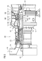
Figur 3- eine Gasturbine,
Figur 4- perspektivisch eine Turbinenschaufel,
- Figur 5
- perspektivisch eine Brennkammer und
- Figur 6
- eine Liste von Superlegierungen.
- FIG. 1, 2
- Embodiments of the layer system,
- FIG. 3
- a gas turbine,
- FIG. 4
- in perspective a turbine blade,
- FIG. 5
- in perspective a combustion chamber and
- FIG. 6
- a list of superalloys.
Die Figuren und die Beschreibung dazu stellen nur Ausführungsbeispiele der Erfindung dar.The figures and the description thereto represent only embodiments of the invention.
In
Insbesondere bei Gasturbinen 100 (
Auf dem Substrat 4 ist eine metallische Schutzschicht 13 vorhanden.In particular with gas turbines 100 (
On the
Erfindungsgemäß umfasst die metallische Schutzschicht 13 zwei in ihrer chemischen Zusammensetzung verschiedene MCrAlX-Schichten 7, 10, wobei die äußere Schicht 10 vorzugsweise einen höheren Chromgehalt aufweist.According to the invention, the metallic
Ebenso vorzugsweise ist auch der Aluminiumgehalt der äußeren Schicht 10 höher als der Aluminiumgehalt der darunterliegenden Schicht 7.
Der Unterschied im Chromgehalt für die zwei Schichten 7, 10 beträgt vorzugsweise (absolut gesehen) vorzugsweise mindestens 1wt% (|Cr(7) - Cr(10)|≥ 1wt%).
Der Unterschied im Aluminiumgehalt für die zwei Schichten 7, 10 beträgt vorzugsweise (absolut gesehen) vorzugsweise mindestens 1wt% (|Al(7) - Al(10)|≥ 1wt%), ganz vorzugsweise mindestens 2wt%.
Vorzugsweise besteht die Schutzschicht 13 nur aus zwei verschiedenen MCrAlX-Schichten 7, 10.Also preferably, the aluminum content of the
The difference in chromium content for the two
The difference in aluminum content for the two
The
Es wird also eine metallische Schutzschicht 13 vorgeschlagen, die gegenüber den bisher verwendeten Schichten eine bessere Oxidationsbeständigkeit als die bisher verwendeten MCrAlX-Schichten bei gleichzeitig gleich gutem thermomechanischem Verhalten aufweist. Dies wird in der Weise erreicht, dass ein Duplex-Schichtsystem angewendet wird, welches den unterschiedlichen Anforderungen in Hinblick auf eine optimierte Diffusions-Wechselwirkung mit dem Basiswerkstoff aufweist und andererseits eine optimierte TGO-Schicht an der Phasengrenze zur Keramik ausbildet. Durch eine unterschiedliche chemische Zusammensetzung der beiden verwendeten MCrAlX-Legierungen wird dieses Ziel erreicht.Thus, a metallic
Der Chromgehalt der inneren Schicht 7 ist höher als der der äußeren Schicht 10, wobei der Aluminiumgehalt der äußeren Schicht 10 höher ist als der Aluminiumgehalt der inneren Schicht 7.
Das gleiche gilt vorzugsweise für ein Schichtsystem 7, 10 mit Yttrium (Y). Höherer Yttriumgehalt bedeutet mindestens einen Unterschied absolut gesehen von 0,15wt%, (|Y(7) - Y(10)|≥ 0,15wt%).The chromium content of the
The same applies preferably to a
Die dem Basiswerkstoff (Substrat 4) naheliegende innere Schicht 7 weist in der chemischen Zusammensetzung des verwendeten Pulvers oder Ingots vorzugsweise folgende Grundzusammensetzung auf (in wt%): Ni etwa 38% bis etwa 66,6% und Co von 8% bis 22%. Diese Grundzusammensetzung führt dazu, dass trotz eines hohen Cr-Gehaltes von 21% bis 29% nur geringe oder keine α-Cr-Phasen auftreten und eine gute Duktilität der Schicht erhalten bleibt. Der relativ hohe Cr- und Y-Gehalt wirkt als Getter für Schwefel im Basiswerkstoff und soll eine schädigende Wirkung auf die TGO verhindern. Der relativ niedrige Al-Gehalt von 4% bis 9% fördert das Duktilitätsverhalten der Schicht 7, führt aber auch zu einer geringen Interdiffusion mit dem Basiswerkstoff (Substrat). Andererseits liegt er noch hoch genug, um die Lebensdauer einer Wärmedämmschicht 16 günstig zu beeinflussen, da genügend Al zur Nachdiffusion vorhanden ist. Die bei dieser Konzentration der Hauptlegierungsbestandteile im neu und betriebsbeanspruchten Zustand auftretenden Phasen sind γ (gamma), γ' und β (Beta).
Der Yttrium-Gehalt soll vorzugsweise größer 0,4wt% bis 0,9wt% betragen und ebenfalls eine Getterwirkung für Schwefel darstellen. Darüber hinaus soll das Yttrium auch in die darüber liegende äußere Schicht 10 diffundieren können. Gegebenenfalls kann die Schicht auch noch Re bis zu 1% enthalten, um die Interdiffusion weiter zu verzögern.The
The yttrium content should preferably be greater than 0.4wt% to 0.9wt% and also a gettering effect for sulfur. In addition, the yttrium should also be able to diffuse into the overlying
Die darüber befindliche äußere MCrAlX-Schicht 10 weist eine im Rahmen der Fertigungstoleranzen vorzugsweise gleiche Dicke wie die erste Schicht 7 auf.The
Diese Grundzusammensetzung führt in Verbindung mit einem abgesenkten Cr-Gehalt von vorzugsweise um 20wt% und einem Al-Gehalt von vorzugsweise 11,5wt% zu einer ausgezeichneten Al2O3-Deckschichtbildung, die noch durch die geringen Gehalte von Si von 0,2% - 0,4% und Y von 0,1% - 0,2% hinsichtlich Ausbildung und Haftung unterstützt wird. Der niedrige Y-Gehalt vermeidet eine innere Oxidation des Yttriums und bildet in der Anfangsphase der Oxidation kein Yttriumaluminat auf der MCrAlX. Dies führt zu einem geringeren Schichtwachstum, und damit geringen Aluminiumverbrauch. Die Schicht 10 hat im Wesentlichen eine Phasenzusammensetzung von Gamma, Beta, ist thermisch stabil und vermeidet spröde Phasen, was wiederum zu guten Duktilitätseigenschaften der MCrAlX-Schicht 10 führt.This basic composition, in combination with a lowered Cr content of preferably 20% by weight and an Al content of preferably 11.5% by weight, leads to an excellent Al 2 O 3 cover layer formation, which is further enhanced by the low contents of Si of 0.2%. - 0.4% and Y from 0.1% - 0.2% in terms of training and liability. The low Y content avoids internal oxidation of the yttrium and does not form yttrium aluminate in the initial phase of the oxidation the MCrAlX. This leads to a lower layer growth, and thus low aluminum consumption. The
Vorzugsweise sind die MCrAlX-Schichten 7, 10 NiCoCrAlY-Schichten.Preferably, the MCrAlX layers 7, 10 are NiCoCrAlY layers.
Die Schutzschicht 13 weist zwei übereinanderliegende Schichten auf, vorzugsweise mit der Zusammensetzung von Schicht 7 (in wt%) :
- Ni,
- Co 8% - 22%
- vorzugsweise 19% - 21%, ganz vorzugsweise 20%,
- Cr 21% - 29%
- vorzugsweise 23% - 25%, ganz vorzugsweise 24%,
Al 4% - 9%- vorzugsweise 6% - 8%, ganz vorzugsweise 7%,
- Y 0,4 - 0,9%
- vorzugsweise > 0,4% - 0,6%, ganz vorzugsweise 0,5%,
- Re 0% - 1,0%
- vorzugsweise 0%,
- vorzugsweise ist obige Auflistung (Ni, Co, Cr, Al, Y, Re) abschließend,
- und
- mit der Zusammensetzung von äußerer Schicht 10:
- Co,
- Ni 29% - 39%
- vorzugsweise 34% - 36%, ganz vorzugsweise 35%,
- Cr 17% - 24%
- vorzugsweise 19% - 21%, ganz vorzugsweise 20%,
- Al 9% - 14%
- vorzugsweise 11% - 12%,
ganz vorzugsweise 11,5%, - Y 0,05% - 0,5%
- vorzugsweise 0,1% - 0,2%,
- optional
- Si 0,1% - 1,1%,
vorzugsweise 0,2% - 0,4%, ganz vorzugsweise 0,3%, vorzugsweise ist obige Auflistung (Co, Ni, Cr, Al, Y, Si) abschließend.
- Ni,
- Co 8% - 22%
- preferably 19% -21%, most preferably 20%,
- Cr 21% - 29%
- preferably 23% -25%, most preferably 24%,
-
Al 4% - 9% - preferably 6% -8%, most preferably 7%,
- Y 0.4 - 0.9%
- preferably> 0.4% - 0.6%, very preferably 0.5%,
- Re 0% - 1.0%
- preferably 0%,
- preferably the above listing (Ni, Co, Cr, Al, Y, Re) is conclusive,
- and
- with the composition of outer layer 10:
- Co,
- Ni 29% - 39%
- preferably 34% -36%, most preferably 35%,
- Cr 17% - 24%
- preferably 19% -21%, most preferably 20%,
- Al 9% - 14%
- preferably 11% -12%, more preferably 11.5%,
- Y 0.05% - 0.5%
- preferably 0.1% -0.2%,
- optional
- Si 0.1% - 1.1%,
- preferably 0.2% -0.4%, most preferably 0.3%, preferably the above listing (Co, Ni, Cr, Al, Y, Si) is final.
Weitere Elemente wie Hf, Zr, P und andere Spurenelemente können bis zu einem Prozentsatz von 0,3% positive Eigenschaften durch gegenseitige Wechselwirkung bewirken.Other elements, such as Hf, Zr, P and other trace elements, can provide up to 0.3% positive properties through mutual interaction.
Die
Die Gasturbine 100 weist im Inneren einen um eine Rotationsachse 102 drehgelagerten Rotor 103 mit einer Welle auf, der auch als Turbinenläufer bezeichnet wird.
Entlang des Rotors 103 folgen aufeinander ein Ansauggehäuse 104, ein Verdichter 105, eine beispielsweise torusartige Brennkammer 110, insbesondere Ringbrennkammer, mit mehreren koaxial angeordneten Brennern 107, eine Turbine 108 und das Abgasgehäuse 109.
Die Ringbrennkammer 110 kommuniziert mit einem beispielsweise ringförmigen Heißgaskanal 111. Dort bilden beispielsweise vier hintereinander geschaltete Turbinenstufen 112 die Turbine 108.
Jede Turbinenstufe 112 ist beispielsweise aus zwei Schaufelringen gebildet. In Strömungsrichtung eines Arbeitsmediums 113 gesehen folgt im Heißgaskanal 111 einer Leitschaufelreihe 115 eine aus Laufschaufeln 120 gebildete Reihe 125.The
The
Along the
The
Each
Die Leitschaufeln 130 sind dabei an einem Innengehäuse 138 eines Stators 143 befestigt, wohingegen die Laufschaufeln 120 einer Reihe 125 beispielsweise mittels einer Turbinenscheibe 133 am Rotor 103 angebracht sind.
An dem Rotor 103 angekoppelt ist ein Generator oder eine Arbeitsmaschine (nicht dargestellt).The guide vanes 130 are fastened to an
Coupled to the
Während des Betriebes der Gasturbine 100 wird vom Verdichter 105 durch das Ansauggehäuse 104 Luft 135 angesaugt und verdichtet. Die am turbinenseitigen Ende des Verdichters 105 bereitgestellte verdichtete Luft wird zu den Brennern 107 geführt und dort mit einem Brennmittel vermischt. Das Gemisch wird dann unter Bildung des Arbeitsmediums 113 in der Brennkammer 110 verbrannt. Von dort aus strömt das Arbeitsmedium 113 entlang des Heißgaskanals 111 vorbei an den Leitschaufeln 130 und den Laufschaufeln 120. An den Laufschaufeln 120 entspannt sich das Arbeitsmedium 113 impulsübertragend, so dass die Laufschaufeln 120 den Rotor 103 antreiben und dieser die an ihn angekoppelte Arbeitsmaschine.During operation of the
Die dem heißen Arbeitsmedium 113 ausgesetzten Bauteile unterliegen während des Betriebes der Gasturbine 100 thermischen Belastungen. Die Leitschaufeln 130 und Laufschaufeln 120 der in Strömungsrichtung des Arbeitsmediums 113 gesehen ersten Turbinenstufe 112 werden neben den die Ringbrennkammer 110 auskleidenden Hitzeschildelementen am meisten thermisch belastet.
Um den dort herrschenden Temperaturen standzuhalten, können diese mittels eines Kühlmittels gekühlt werden.
Ebenso können Substrate der Bauteile eine gerichtete Struktur aufweisen, d.h. sie sind einkristallin (SX-Struktur) oder weisen nur längsgerichtete Körner auf (DS-Struktur).
Als Material für die Bauteile, insbesondere für die Turbinenschaufel 120, 130 und Bauteile der Brennkammer 110 werden beispielsweise eisen-, nickel- oder kobaltbasierte Superlegierungen verwendet.
Solche Superlegierungen sind beispielsweise aus der
To withstand the prevailing temperatures, they can be cooled by means of a coolant.
Likewise, substrates of the components can have a directional structure, ie they are monocrystalline (SX structure) or have only longitudinal grains (DS structure).
As the material for the components, in particular for the
Such superalloys are for example from
Die Leitschaufel 130 weist einen dem Innengehäuse 138 der Turbine 108 zugewandten Leitschaufelfuß (hier nicht dargestellt) und einen dem Leitschaufelfuß gegenüberliegenden Leitschaufelkopf auf. Der Leitschaufelkopf ist dem Rotor 103 zugewandt und an einem Befestigungsring 140 des Stators 143 festgelegt.The
Die
Die Strömungsmaschine kann eine Gasturbine eines Flugzeugs oder eines Kraftwerks zur Elektrizitätserzeugung, eine Dampfturbine oder ein Kompressor sein.The turbomachine may be a gas turbine of an aircraft or a power plant for power generation, a steam turbine or a compressor.
Die Schaufel 120, 130 weist entlang der Längsachse 121 aufeinander folgend einen Befestigungsbereich 400, eine daran angrenzende Schaufelplattform 403 sowie ein Schaufelblatt 406 und eine Schaufelspitze 415 auf.
Als Leitschaufel 130 kann die Schaufel 130 an ihrer Schaufelspitze 415 eine weitere Plattform aufweisen (nicht dargestellt).The
As a
Im Befestigungsbereich 400 ist ein Schaufelfuß 183 gebildet, der zur Befestigung der Laufschaufeln 120, 130 an einer Welle oder einer Scheibe dient (nicht dargestellt).
Der Schaufelfuß 183 ist beispielsweise als Hammerkopf ausgestaltet. Andere Ausgestaltungen als Tannenbaum- oder Schwalbenschwanzfuß sind möglich.
Die Schaufel 120, 130 weist für ein Medium, das an dem Schaufelblatt 406 vorbeiströmt, eine Anströmkante 409 und eine Abströmkante 412 auf.In the mounting
The
The
Bei herkömmlichen Schaufeln 120, 130 werden in allen Bereichen 400, 403, 406 der Schaufel 120, 130 beispielsweise massive metallische Werkstoffe, insbesondere Superlegierungen verwendet.
Solche Superlegierungen sind beispielsweise aus der
Such superalloys are for example from
Die Schaufel 120, 130 kann hierbei durch ein Gussverfahren, auch mittels gerichteter Erstarrung, durch ein Schmiedeverfahren, durch ein Fräsverfahren oder Kombinationen daraus gefertigt sein.The
Werkstücke mit einkristalliner Struktur oder Strukturen werden als Bauteile für Maschinen eingesetzt, die im Betrieb hohen mechanischen, thermischen und/oder chemischen Belastungen ausgesetzt sind.
Die Fertigung von derartigen einkristallinen Werkstücken erfolgt z.B. durch gerichtetes Erstarren aus der Schmelze. Es handelt sich dabei um Gießverfahren, bei denen die flüssige metallische Legierung zur einkristallinen Struktur, d.h. zum einkristallinen Werkstück, oder gerichtet erstarrt.
Dabei werden dendritische Kristalle entlang dem Wärmefluss ausgerichtet und bilden entweder eine stängelkristalline Kornstruktur (kolumnar, d.h. Körner, die über die ganze Länge des Werkstückes verlaufen und hier, dem allgemeinen Sprachgebrauch nach, als gerichtet erstarrt bezeichnet werden) oder eine einkristalline Struktur, d.h. das ganze Werkstück besteht aus einem einzigen Kristall. In diesen Verfahren muss man den Übergang zur globulitischen (polykristallinen) Erstarrung meiden, da sich durch ungerichtetes Wachstum notwendigerweise transversale und longitudinale Korngrenzen ausbilden, welche die guten Eigenschaften des gerichtet erstarrten oder einkristallinen Bauteiles zunichte machen.
Ist allgemein von gerichtet erstarrten Gefügen die Rede, so sind damit sowohl Einkristalle gemeint, die keine Korngrenzen oder höchstens Kleinwinkelkorngrenzen aufweisen, als auch Stängelkristallstrukturen, die wohl in longitudinaler Richtung verlaufende Korngrenzen, aber keine transversalen Korngrenzen aufweisen. Bei diesen zweitgenannten kristallinen Strukturen spricht man auch von gerichtet erstarrten Gefügen (directionally solidified structures).
Solche Verfahren sind aus der
The production of such monocrystalline workpieces, for example, by directed solidification from the melt. These are casting methods in which the liquid metallic alloy solidifies into a monocrystalline structure, ie a single-crystal workpiece, or directionally.
Here, dendritic crystals are aligned along the heat flow and form either a columnar grain structure (columnar, ie grains that run the entire length of the workpiece and here, in common parlance, referred to as directionally solidified) or a monocrystalline structure, ie the whole Workpiece consists of a single crystal. In these processes, it is necessary to avoid the transition to globulitic (polycrystalline) solidification, since non-directional growth necessarily produces transverse and longitudinal grain boundaries which negate the good properties of the directionally solidified or monocrystalline component.
The term generally refers to directionally solidified microstructures, which means both single crystals that have no grain boundaries or at most small angle grain boundaries, and stem crystal structures that have probably longitudinal grain boundaries but no transverse grain boundaries. These second-mentioned crystalline structures are also known as directionally solidified structures.
Such methods are known from
Ebenso können die Schaufeln 120, 130 Beschichtungen gegen Korrosion oder Oxidation aufweisen, z. B. (MCrAlX; M ist zumindest ein Element der Gruppe Eisen (Fe), Kobalt (Co), Nickel (Ni), X ist ein Aktivelement und steht für Yttrium (Y) und/oder Silizium und/oder zumindest ein Element der Seltenen Erden, bzw. Hafnium (Hf)). Solche Legierungen sind bekannt aus der
Die Dichte liegt vorzugsweise bei 95% der theoretischen Dichte.
Auf der MCrAlX-Schicht (als Zwischenschicht oder als äußerste Schicht) bildet sich eine schützende Aluminiumoxidschicht (TGO = thermal grown oxide layer).Likewise, the
The density is preferably 95% of the theoretical density.
A protective aluminum oxide layer (TGO = thermal grown oxide layer) is formed on the MCrAlX layer (as an intermediate layer or as the outermost layer).
Vorzugsweise weist die Schichtzusammensetzung Co-30Ni-28Cr-8Al-0,6Y-0,7Si oder Co-28Ni-24Cr-10Al-0,6Y auf. Neben diesen kobaltbasierten Schutzbeschichtungen werden auch vorzugsweise nickelbasierte Schutzschichten verwendet wie Ni-10Cr-12Al-0,6Y-3Re oder Ni-12Co-21Cr-11Al-0,4Y-2Re oder Ni-25Co-17Cr-10Al-0,4Y-1,5Re.Preferably, the layer composition comprises Co-30Ni-28Cr-8Al-0.6Y-0.7Si or Co-28Ni-24Cr-10Al-0.6Y. In addition to these cobalt-based protective coatings, nickel-based protective layers such as Ni-10Cr-12Al-0.6Y-3Re or Ni-12Co-21Cr-11Al-0.4Y-2Re or Ni-25Co-17Cr-10Al-0.4Y-1 are also preferably used , 5RE.
Auf der MCrAlX kann noch eine Wärmedämmschicht vorhanden sein, die vorzugsweise die äußerste Schicht ist, und besteht beispielsweise aus ZrO2, Y2O3-ZrO2, d.h. sie ist nicht, teilweise oder vollständig stabilisiert durch Yttriumoxid und/oder Kalziumoxid und/oder Magnesiumoxid.
Die Wärmedämmschicht bedeckt die gesamte MCrAlX-Schicht. Durch geeignete Beschichtungsverfahren wie z.B. Elektronenstrahlverdampfen (EB-PVD) werden stängelförmige Körner in der Wärmedämmschicht erzeugt.
Andere Beschichtungsverfahren sind denkbar, z.B. atmosphärisches Plasmaspritzen (APS), LPPS, VPS oder CVD. Die Wärmedämmschicht kann poröse, mikro- oder makrorissbehaftete Körner zur besseren Thermoschockbeständigkeit aufweisen. Die Wärmedämmschicht ist also vorzugsweise poröser als die MCrAlX-Schicht.On the MCrAlX may still be present a thermal barrier coating, which is preferably the outermost layer, and consists for example of ZrO 2 , Y 2 O 3 -ZrO 2 , ie it is not, partially or completely stabilized by yttria and / or calcium oxide and / or magnesium oxide.
The thermal barrier coating covers the entire MCrAlX layer. By means of suitable coating processes, such as electron beam evaporation (EB-PVD), stalk-shaped grains are produced in the thermal barrier coating.
Other coating methods are conceivable, for example atmospheric plasma spraying (APS), LPPS, VPS or CVD. The thermal barrier coating may have porous, micro- or macro-cracked grains for better thermal shock resistance. The thermal barrier coating is therefore preferably more porous than the MCrAlX layer.
Die Schaufel 120, 130 kann hohl oder massiv ausgeführt sein. Wenn die Schaufel 120, 130 gekühlt werden soll, ist sie hohl und weist ggf. noch Filmkühllöcher 418 (gestrichelt angedeutet) auf.The
Die
Zur Erzielung eines vergleichsweise hohen Wirkungsgrades ist die Brennkammer 110 für eine vergleichsweise hohe Temperatur des Arbeitsmediums M von etwa 1000°C bis 1600°C ausgelegt. Um auch bei diesen, für die Materialien ungünstigen Betriebsparametern eine vergleichsweise lange Betriebsdauer zu ermöglichen, ist die Brennkammerwand 153 auf ihrer dem Arbeitsmedium M zugewandten Seite mit einer aus Hitzeschildelementen 155 gebildeten Innenauskleidung versehen.To achieve a comparatively high efficiency, the
Aufgrund der hohen Temperaturen im Inneren der Brennkammer 110 kann zudem für die Hitzeschildelemente 155 bzw. für deren Halteelemente ein Kühlsystem vorgesehen sein. Die Hitzeschildelemente 155 sind dann beispielsweise hohl und weisen ggf. noch in den Brennkammerraum 154 mündende Kühllöcher (nicht dargestellt) auf.Due to the high temperatures inside the
Jedes Hitzeschildelement 155 aus einer Legierung ist arbeitsmediumsseitig mit einer besonders hitzebeständigen Schutzschicht (MCrAlX-Schicht und/oder keramische Beschichtung) ausgestattet oder ist aus hochtemperaturbeständigem Material (massive keramische Steine) gefertigt.
Diese Schutzschichten können ähnlich der Turbinenschaufeln sein, also bedeutet beispielsweise MCrAlX: M ist zumindest ein Element der Gruppe Eisen (Fe), Kobalt (Co), Nickel (Ni), X ist ein Aktivelement und steht für Yttrium (Y) und/oder Silizium und/oder zumindest ein Element der Seltenen Erden, bzw. Hafnium (Hf). Solche Legierungen sind bekannt aus der
These protective layers may be similar to the turbine blades, so for example MCrAlX means: M is at least an element of the group iron (Fe), cobalt (Co), nickel (Ni), X is an active element and stands for yttrium (Y) and / or silicon and / or at least one element of the rare earths, or hafnium (Hf) , Such alloys are known from the
Auf der MCrAlX kann noch eine beispielsweise keramische Wärmedämmschicht vorhanden sein und besteht beispielsweise aus ZrO2, Y2O3-ZrO2, d.h. sie ist nicht, teilweise oder vollständig stabilisiert durch Yttriumoxid und/oder Kalziumoxid und/oder Magnesiumoxid.
Durch geeignete Beschichtungsverfahren wie z.B. Elektronenstrahlverdampfen (EB-PVD) werden stängelförmige Körner in der Wärmedämmschicht erzeugt.
Andere Beschichtungsverfahren sind denkbar, z.B. atmosphärisches Plasmaspritzen (APS), LPPS, VPS oder CVD. Die Wärmedämmschicht kann poröse, mikro- oder makrorissbehaftete Körner zur besseren Thermoschockbeständigkeit aufweisen.On the MCrAlX, for example, a ceramic thermal barrier coating may be present and consists for example of ZrO 2 , Y 2 O 3 -ZrO 2 , ie it is not, partially or completely stabilized by yttria and / or calcium oxide and / or magnesium oxide.
By means of suitable coating processes, such as electron beam evaporation (EB-PVD), stalk-shaped grains are produced in the thermal barrier coating.
Other coating methods are conceivable, for example atmospheric plasma spraying (APS), LPPS, VPS or CVD. The thermal barrier coating may have porous, micro- or macro-cracked grains for better thermal shock resistance.
Wiederaufarbeitung (Refurbishment) bedeutet, dass Turbinenschaufeln 120, 130, Hitzeschildelemente 155 nach ihrem Einsatz gegebenenfalls von Schutzschichten befreit werden müssen (z.B. durch Sandstrahlen). Danach erfolgt eine Entfernung der Korrosions- und/oder Oxidationsschichten bzw. -produkte. Gegebenenfalls werden auch noch Risse in der Turbinenschaufel 120, 130 oder dem Hitzeschildelement 155 repariert. Danach erfolgt eine Wiederbeschichtung der Turbinenschaufeln 120, 130, Hitzeschildelemente 155 und ein erneuter Einsatz der Turbinenschaufeln 120, 130 oder der Hitzeschildelemente 155.Refurbishment means that
Claims (13)
bei dem die innere MCrAlX-Schicht (7) aufweist (in wt%):
in which the inner MCrAlX layer (7) has (in wt%):
bei dem die äußere NiCoCrAlX-Schicht (10) zumindest ein Element aus der Gruppe Hafnium (Hf), Zirkon (Zr), Phosphor (P) aufweist,
aufweist.Layer system according to claim 1 or 2,
in which the outer NiCoCrAlX layer (10) has at least one element from the group hafnium (Hf), zirconium (Zr), phosphorus (P),
having.
bei dem das Schichtsystem besteht aus:
in which the shift system consists of:
bei dem das Schichtsystem besteht aus:
in which the shift system consists of:
bei dem X = Yttrium ist.Layer system according to claim 1, 2, 3, 4, 5, 6, 7, 8, 9, 10 or 12,
where X = yttrium.
Priority Applications (1)
| Application Number | Priority Date | Filing Date | Title |
|---|---|---|---|
| EP13005373.9A EP2698450A1 (en) | 2009-01-08 | 2009-12-14 | MCrAIX coating with different chrome and aluminium contents |
Applications Claiming Priority (3)
| Application Number | Priority Date | Filing Date | Title |
|---|---|---|---|
| EP09000160A EP2206805A1 (en) | 2009-01-08 | 2009-01-08 | MCrAIX coating with different chrome and aluminium contents |
| EP13005373.9A EP2698450A1 (en) | 2009-01-08 | 2009-12-14 | MCrAIX coating with different chrome and aluminium contents |
| EP09795967A EP2376677A1 (en) | 2009-01-08 | 2009-12-14 | Mcralx layer having differing chromium and aluminum content |
Related Parent Applications (1)
| Application Number | Title | Priority Date | Filing Date |
|---|---|---|---|
| EP09795967A Division EP2376677A1 (en) | 2009-01-08 | 2009-12-14 | Mcralx layer having differing chromium and aluminum content |
Publications (1)
| Publication Number | Publication Date |
|---|---|
| EP2698450A1 true EP2698450A1 (en) | 2014-02-19 |
Family
ID=40489392
Family Applications (3)
| Application Number | Title | Priority Date | Filing Date |
|---|---|---|---|
| EP09000160A Withdrawn EP2206805A1 (en) | 2009-01-08 | 2009-01-08 | MCrAIX coating with different chrome and aluminium contents |
| EP09795967A Withdrawn EP2376677A1 (en) | 2009-01-08 | 2009-12-14 | Mcralx layer having differing chromium and aluminum content |
| EP13005373.9A Withdrawn EP2698450A1 (en) | 2009-01-08 | 2009-12-14 | MCrAIX coating with different chrome and aluminium contents |
Family Applications Before (2)
| Application Number | Title | Priority Date | Filing Date |
|---|---|---|---|
| EP09000160A Withdrawn EP2206805A1 (en) | 2009-01-08 | 2009-01-08 | MCrAIX coating with different chrome and aluminium contents |
| EP09795967A Withdrawn EP2376677A1 (en) | 2009-01-08 | 2009-12-14 | Mcralx layer having differing chromium and aluminum content |
Country Status (6)
| Country | Link |
|---|---|
| US (1) | US20110268987A1 (en) |
| EP (3) | EP2206805A1 (en) |
| JP (1) | JP2012514692A (en) |
| CN (1) | CN102272354B (en) |
| RU (1) | RU2011133090A (en) |
| WO (1) | WO2010079049A1 (en) |
Families Citing this family (11)
| Publication number | Priority date | Publication date | Assignee | Title |
|---|---|---|---|---|
| EP2341166A1 (en) * | 2009-12-29 | 2011-07-06 | Siemens Aktiengesellschaft | Nano and micro structured ceramic thermal barrier coating |
| KR20120125551A (en) * | 2010-02-26 | 2012-11-15 | 지멘스 악티엔게젤샤프트 | Two layered metallic bondcoat |
| US9556748B2 (en) | 2011-09-12 | 2017-01-31 | Siemens Aktiengesellschaft | Layer system with double MCrAlX metallic layer |
| US20130115072A1 (en) * | 2011-11-09 | 2013-05-09 | General Electric Company | Alloys for bond coatings and articles incorporating the same |
| EP2639336A1 (en) * | 2012-03-16 | 2013-09-18 | Siemens Aktiengesellschaft | Coating system with NiCoCrAlY double-protection coat with varying chromium content and alloy |
| EP2682488A1 (en) * | 2012-07-05 | 2014-01-08 | Siemens Aktiengesellschaft | Coating system with NiCoCrAlY double-protection coat with varying chromium content and alloy |
| US20140186656A1 (en) * | 2012-12-31 | 2014-07-03 | United Technologies Corporation | Spallation-Resistant Thermal Barrier Coating |
| US10113226B2 (en) | 2013-03-15 | 2018-10-30 | United Technologies Corporation | Spallation-resistant thermal barrier coating |
| EP3075954A1 (en) * | 2015-04-01 | 2016-10-05 | Siemens Aktiengesellschaft | Vane segment for a gas turbine |
| EP3784813A1 (en) * | 2018-04-24 | 2021-03-03 | Oerlikon Surface Solutions AG, Pfäffikon | Coating comprising mcral-x coating layer |
| CN116288207B (en) * | 2023-03-21 | 2024-04-05 | 浙江大学 | Thermal barrier coating, preparation method thereof and application thereof in high-temperature alloy |
Citations (15)
| Publication number | Priority date | Publication date | Assignee | Title |
|---|---|---|---|---|
| EP0486489B1 (en) | 1989-08-10 | 1994-11-02 | Siemens Aktiengesellschaft | High-temperature-resistant, corrosion-resistant coating, in particular for components of gas turbines |
| EP0412397B1 (en) | 1989-08-10 | 1998-03-25 | Siemens Aktiengesellschaft | Rhenium-containing protective coating with high corrosion and oxidation resistance |
| EP0892090A1 (en) | 1997-02-24 | 1999-01-20 | Sulzer Innotec Ag | Method for manufacturing single crystal structures |
| EP0786017B1 (en) | 1994-10-14 | 1999-03-24 | Siemens Aktiengesellschaft | Protective layer for protecting parts against corrosion, oxidation and excessive thermal stresses, as well as process for producing the same |
| WO1999067435A1 (en) | 1998-06-23 | 1999-12-29 | Siemens Aktiengesellschaft | Directionally solidified casting with improved transverse stress rupture strength |
| US6024792A (en) | 1997-02-24 | 2000-02-15 | Sulzer Innotec Ag | Method for producing monocrystalline structures |
| WO2000044949A1 (en) | 1999-01-28 | 2000-08-03 | Siemens Aktiengesellschaft | Nickel base superalloy with good machinability |
| EP1306454A1 (en) | 2001-10-24 | 2003-05-02 | Siemens Aktiengesellschaft | Rhenium containing protective coating protecting a product against corrosion and oxidation at high temperatures |
| EP1319729A1 (en) | 2001-12-13 | 2003-06-18 | Siemens Aktiengesellschaft | High temperature resistant part, made of single-crystal or polycrystalline nickel-base superalloy |
| EP1204776B1 (en) | 1999-07-29 | 2004-06-02 | Siemens Aktiengesellschaft | High-temperature part and method for producing the same |
| EP1798299A1 (en) * | 2005-12-14 | 2007-06-20 | Siemens Aktiengesellschaft | Alloy, protective coating and component |
| EP1816222A1 (en) * | 2006-01-20 | 2007-08-08 | Siemens Aktiengesellschaft | Coating system with two-layered metallic protective coating |
| EP1845171A1 (en) * | 2006-04-10 | 2007-10-17 | Siemens Aktiengesellschaft | Coating system formed with layers having different particle sizes |
| EP1925687A1 (en) * | 2006-11-24 | 2008-05-28 | Siemens Aktiengesellschaft | NICoCrAl-layer and metallic layer system |
| EP2128285A1 (en) * | 2008-05-20 | 2009-12-02 | Siemens Aktiengesellschaft | Two-layer MCrAIX coating with different cobalt and nickel contents |
Family Cites Families (15)
| Publication number | Priority date | Publication date | Assignee | Title |
|---|---|---|---|---|
| JPS55161041A (en) * | 1979-05-29 | 1980-12-15 | Howmet Turbine Components | Covering material |
| US4696855A (en) * | 1986-04-28 | 1987-09-29 | United Technologies Corporation | Multiple port plasma spray apparatus and method for providing sprayed abradable coatings |
| JPH03503184A (en) * | 1988-02-05 | 1991-07-18 | シーメンス、アクチエンゲゼルシヤフト | Metal objects, especially gas turbine blades with protective coatings |
| US5499905A (en) * | 1988-02-05 | 1996-03-19 | Siemens Aktiengesellschaft | Metallic component of a gas turbine installation having protective coatings |
| JP2949605B2 (en) * | 1991-09-20 | 1999-09-20 | 株式会社日立製作所 | Alloy-coated gas turbine blade and method of manufacturing the same |
| JPH09176821A (en) * | 1995-12-21 | 1997-07-08 | Toshiba Corp | Radiation shield coating member and its production |
| US6435830B1 (en) * | 1999-12-20 | 2002-08-20 | United Technologies Corporation | Article having corrosion resistant coating |
| EP1260612A1 (en) * | 2001-05-25 | 2002-11-27 | ALSTOM (Switzerland) Ltd | A bond or overlay MCrAIY-coating |
| EP1295969A1 (en) * | 2001-09-22 | 2003-03-26 | ALSTOM (Switzerland) Ltd | Method of growing a MCrAIY-coating and an article coated with the MCrAIY-coating |
| JP3916484B2 (en) * | 2002-03-05 | 2007-05-16 | 独立行政法人科学技術振興機構 | Ni alloy heat resistant material excellent in high temperature oxidation resistance and method for producing the same |
| EP1380672A1 (en) * | 2002-07-09 | 2004-01-14 | Siemens Aktiengesellschaft | Highly oxidation resistant component |
| CN100526064C (en) * | 2005-04-05 | 2009-08-12 | 中国科学院金属研究所 | Nanometer crystalline compound coating and its preparation process |
| CN100482855C (en) * | 2006-03-08 | 2009-04-29 | 中国科学院金属研究所 | CrN/CrAlN protective coating capable of resisting high temperature corrosion in wide temperature range and preparing method |
| JP2007262447A (en) * | 2006-03-27 | 2007-10-11 | Mitsubishi Heavy Ind Ltd | Oxidation-resistant film and its deposition method, thermal barrier coating, heat-resistant member, and gas turbine |
| US7507484B2 (en) * | 2006-12-01 | 2009-03-24 | Siemens Energy, Inc. | Bond coat compositions and arrangements of same capable of self healing |
-
2009
- 2009-01-08 EP EP09000160A patent/EP2206805A1/en not_active Withdrawn
- 2009-12-14 RU RU2011133090/02A patent/RU2011133090A/en not_active Application Discontinuation
- 2009-12-14 US US13/142,627 patent/US20110268987A1/en not_active Abandoned
- 2009-12-14 EP EP09795967A patent/EP2376677A1/en not_active Withdrawn
- 2009-12-14 WO PCT/EP2009/067097 patent/WO2010079049A1/en active Application Filing
- 2009-12-14 EP EP13005373.9A patent/EP2698450A1/en not_active Withdrawn
- 2009-12-14 JP JP2011544827A patent/JP2012514692A/en not_active Ceased
- 2009-12-14 CN CN2009801540466A patent/CN102272354B/en not_active Expired - Fee Related
Patent Citations (15)
| Publication number | Priority date | Publication date | Assignee | Title |
|---|---|---|---|---|
| EP0486489B1 (en) | 1989-08-10 | 1994-11-02 | Siemens Aktiengesellschaft | High-temperature-resistant, corrosion-resistant coating, in particular for components of gas turbines |
| EP0412397B1 (en) | 1989-08-10 | 1998-03-25 | Siemens Aktiengesellschaft | Rhenium-containing protective coating with high corrosion and oxidation resistance |
| EP0786017B1 (en) | 1994-10-14 | 1999-03-24 | Siemens Aktiengesellschaft | Protective layer for protecting parts against corrosion, oxidation and excessive thermal stresses, as well as process for producing the same |
| EP0892090A1 (en) | 1997-02-24 | 1999-01-20 | Sulzer Innotec Ag | Method for manufacturing single crystal structures |
| US6024792A (en) | 1997-02-24 | 2000-02-15 | Sulzer Innotec Ag | Method for producing monocrystalline structures |
| WO1999067435A1 (en) | 1998-06-23 | 1999-12-29 | Siemens Aktiengesellschaft | Directionally solidified casting with improved transverse stress rupture strength |
| WO2000044949A1 (en) | 1999-01-28 | 2000-08-03 | Siemens Aktiengesellschaft | Nickel base superalloy with good machinability |
| EP1204776B1 (en) | 1999-07-29 | 2004-06-02 | Siemens Aktiengesellschaft | High-temperature part and method for producing the same |
| EP1306454A1 (en) | 2001-10-24 | 2003-05-02 | Siemens Aktiengesellschaft | Rhenium containing protective coating protecting a product against corrosion and oxidation at high temperatures |
| EP1319729A1 (en) | 2001-12-13 | 2003-06-18 | Siemens Aktiengesellschaft | High temperature resistant part, made of single-crystal or polycrystalline nickel-base superalloy |
| EP1798299A1 (en) * | 2005-12-14 | 2007-06-20 | Siemens Aktiengesellschaft | Alloy, protective coating and component |
| EP1816222A1 (en) * | 2006-01-20 | 2007-08-08 | Siemens Aktiengesellschaft | Coating system with two-layered metallic protective coating |
| EP1845171A1 (en) * | 2006-04-10 | 2007-10-17 | Siemens Aktiengesellschaft | Coating system formed with layers having different particle sizes |
| EP1925687A1 (en) * | 2006-11-24 | 2008-05-28 | Siemens Aktiengesellschaft | NICoCrAl-layer and metallic layer system |
| EP2128285A1 (en) * | 2008-05-20 | 2009-12-02 | Siemens Aktiengesellschaft | Two-layer MCrAIX coating with different cobalt and nickel contents |
Also Published As
| Publication number | Publication date |
|---|---|
| RU2011133090A (en) | 2013-02-20 |
| CN102272354B (en) | 2013-10-23 |
| JP2012514692A (en) | 2012-06-28 |
| EP2376677A1 (en) | 2011-10-19 |
| CN102272354A (en) | 2011-12-07 |
| US20110268987A1 (en) | 2011-11-03 |
| EP2206805A1 (en) | 2010-07-14 |
| WO2010079049A1 (en) | 2010-07-15 |
Similar Documents
| Publication | Publication Date | Title |
|---|---|---|
| EP2698450A1 (en) | MCrAIX coating with different chrome and aluminium contents | |
| EP2612949B1 (en) | Alloy, protective layer and component | |
| EP1925687A1 (en) | NICoCrAl-layer and metallic layer system | |
| EP2465958A1 (en) | Alloy, protective coating and component | |
| EP2279282A1 (en) | Method for the production of an optimized bonding agent layer by means of partial evaporation of the bonding agent layer, and a layer system | |
| EP1798299B1 (en) | Alloy, protective coating and component | |
| EP1806418A1 (en) | Alloy, protective coating for protecting a structural member against corrosion and oxidation at high temperatures and structural member | |
| EP1790743A1 (en) | Alloy, protective layer and component | |
| WO2009141197A1 (en) | Two-layer mcra1x coating having different contents of cobalt and nickel | |
| EP1854899A1 (en) | Alloy, protective layer and component | |
| WO2013053509A1 (en) | Ceramic double layer based on zirconium oxide | |
| EP2710167B1 (en) | Alloy, protective coating and component | |
| EP2474413A1 (en) | Alloy, protective coating and component | |
| EP2128285A1 (en) | Two-layer MCrAIX coating with different cobalt and nickel contents | |
| EP2845924A1 (en) | Porous ceramic coating system | |
| EP2699713B1 (en) | Coating system with two-ply metallic layer | |
| EP2661370B1 (en) | Alloy, protective layer and component | |
| EP2611949B1 (en) | Nickel base alloy, protective coating, and component | |
| WO2015071015A1 (en) | Porous ceramic coating system | |
| EP1790746B1 (en) | Alloy, protective layer and component | |
| EP2206806A1 (en) | Two-layer MCrAIX coating with different cobalt and nickel contents | |
| EP2756107B1 (en) | Alloy, protective coating and component | |
| EP2247763A1 (en) | Alloy, high-temperature corrosion protection layer and layer system | |
| EP2354260A1 (en) | Alloy, protective layer and component | |
| EP1806419B1 (en) | Alloy, protective coating for protecting a structural member against corrosion and oxidation at high temperatures and structural member |
Legal Events
| Date | Code | Title | Description |
|---|---|---|---|
| AC | Divisional application: reference to earlier application |
Ref document number: 2376677 Country of ref document: EP Kind code of ref document: P |
|
| AK | Designated contracting states |
Kind code of ref document: A1 Designated state(s): AT BE BG CH CY CZ DE DK EE ES FI FR GB GR HR HU IE IS IT LI LT LU LV MC MK MT NL NO PL PT RO SE SI SK SM TR |
|
| AX | Request for extension of the european patent |
Extension state: AL BA RS |
|
| PUAI | Public reference made under article 153(3) epc to a published international application that has entered the european phase |
Free format text: ORIGINAL CODE: 0009012 |
|
| RAP1 | Party data changed (applicant data changed or rights of an application transferred) |
Owner name: SIEMENS AKTIENGESELLSCHAFT |
|
| STAA | Information on the status of an ep patent application or granted ep patent |
Free format text: STATUS: THE APPLICATION IS DEEMED TO BE WITHDRAWN |
|
| 18D | Application deemed to be withdrawn |
Effective date: 20140820 |